EP3567987A1 - Induction coil assembly - Google Patents
Induction coil assembly Download PDFInfo
- Publication number
- EP3567987A1 EP3567987A1 EP18171367.8A EP18171367A EP3567987A1 EP 3567987 A1 EP3567987 A1 EP 3567987A1 EP 18171367 A EP18171367 A EP 18171367A EP 3567987 A1 EP3567987 A1 EP 3567987A1
- Authority
- EP
- European Patent Office
- Prior art keywords
- coil assembly
- induction coil
- fix
- bottom plate
- assembly according
- Prior art date
- Legal status (The legal status is an assumption and is not a legal conclusion. Google has not performed a legal analysis and makes no representation as to the accuracy of the status listed.)
- Granted
Links
Images

Classifications
-
- H—ELECTRICITY
- H05—ELECTRIC TECHNIQUES NOT OTHERWISE PROVIDED FOR
- H05B—ELECTRIC HEATING; ELECTRIC LIGHT SOURCES NOT OTHERWISE PROVIDED FOR; CIRCUIT ARRANGEMENTS FOR ELECTRIC LIGHT SOURCES, IN GENERAL
- H05B6/00—Heating by electric, magnetic or electromagnetic fields
- H05B6/02—Induction heating
- H05B6/10—Induction heating apparatus, other than furnaces, for specific applications
- H05B6/12—Cooking devices
- H05B6/1209—Cooking devices induction cooking plates or the like and devices to be used in combination with them
- H05B6/1245—Cooking devices induction cooking plates or the like and devices to be used in combination with them with special coil arrangements
-
- H—ELECTRICITY
- H05—ELECTRIC TECHNIQUES NOT OTHERWISE PROVIDED FOR
- H05B—ELECTRIC HEATING; ELECTRIC LIGHT SOURCES NOT OTHERWISE PROVIDED FOR; CIRCUIT ARRANGEMENTS FOR ELECTRIC LIGHT SOURCES, IN GENERAL
- H05B2206/00—Aspects relating to heating by electric, magnetic, or electromagnetic fields covered by group H05B6/00
- H05B2206/02—Induction heating
- H05B2206/022—Special supports for the induction coils
-
- Y—GENERAL TAGGING OF NEW TECHNOLOGICAL DEVELOPMENTS; GENERAL TAGGING OF CROSS-SECTIONAL TECHNOLOGIES SPANNING OVER SEVERAL SECTIONS OF THE IPC; TECHNICAL SUBJECTS COVERED BY FORMER USPC CROSS-REFERENCE ART COLLECTIONS [XRACs] AND DIGESTS
- Y02—TECHNOLOGIES OR APPLICATIONS FOR MITIGATION OR ADAPTATION AGAINST CLIMATE CHANGE
- Y02B—CLIMATE CHANGE MITIGATION TECHNOLOGIES RELATED TO BUILDINGS, e.g. HOUSING, HOUSE APPLIANCES OR RELATED END-USER APPLICATIONS
- Y02B40/00—Technologies aiming at improving the efficiency of home appliances, e.g. induction cooking or efficient technologies for refrigerators, freezers or dish washers
Definitions
- the present invention relates to an induction coil assembly comprising a bottom plate on which an induction heating element is placed, such induction heating element comprising a coil mounted on a support element, means being provided for fastening the heating element to the bottom plate.
- an induction coil assembly of the above type is disclosed by WO2015/049602 in which the means for fastening the heating element to the bottom plate comprises hook-shaped elements on the outer edge of a disc-shaped support element.
- This construction implies that each disc-shaped support element must have the above hook-shaped fastening element corresponding to specific apertures in the bottom plate. This increases the complexity of the induction coil assembly.
- the support element may have various shapes, even if the disc-shape configuration is the most ususal.
- a cooktop assembly 10 includes a substrate 12 containing at least one coil assembly 14.
- the substrate 12 is usually an aluminum plate which acts as a partition element and on which heating coils are mounted.
- each coil assembly 14 is connected to the substrate 12 by a central fix and turn element 16.
- the fix and turn element 16 extends through a shaped opening 22 defined by the substrate 12 and couples the coil 18 and the coil wire support 20 to the substrate 12.
- the shaped opening presents a plurality of notches configured to cooperate with the fix and turn element 16 for fastening the heating element.
- the plastic support usually comprises ferrite bars (not shown) for shielding the electromagnetic field.
- the fix and turn element 16 also functions as a receptacle for a sensor 24A ( fig. 2A ) or 24B ( fig. 2B ) for the coil assembly 14.
- the sensor 24A, 24B removable fits within the top portion of the fix and turn element 16, allowing the fix and turn element 16 to be assembled with the substrate 12 separately from the coil assembly 14.
- the fix and turn element 16 can be configured to receive a variety of sensor holder or spring types as needed, for instance temperature sensors, depending on the particular coil assembly 14.
- Fig. 2A shows an embodiment wherein the sensor 24A includes a cover 26.
- Fig. 2B shows a second embodiment wherein the sensor 24B includes wiring 28 extending down through the coil 18, plastic support 20, and substrate 12, both of which can be used interchangeably with the fix and turn element 16.
- the fix and turn element 16 is shown fully engaged with the substrate 12 to retain the coil assembly 14. Because the fix and turn element 16 retains the coil assembly 14 within the center thereof, a standard size and shape can be used to couple coil assemblies 14 of various sizes and shapes to the substrate 12, eliminating the need for numerous connection options and allowing faster assembly of the coil 14.
- the fix and turn element 16 includes a top portion 30 and a bottom portion 32.
- the top portion 30 includes a recess 34 with a step portion 36 to engage with various embodiments of the above-described sensor holder or spring.
- the top portion defines an opening 38 that extends through the bottom portion, for example, to allow for wiring to reach the board sensor connector.
- the bottom portion 32 includes a continuous lower surface 40 and a plurality of flanges 42 spaced vertically from the surface 40 and radially from each other to pass through an opening in the substrate 12, when inserted in a first position, until the surface 40 moves into contact with substrate 12.
- the fix and turn element 16 is then rotated into a second position wherein portions of the substrate 12 are captured between the flanges 42 and surface 40. This fixed second position prevents the fix and turn element 16 from detaching from the substrate 12, allowing it to hold a corresponding coil assembly in place.
Landscapes
- Physics & Mathematics (AREA)
- Electromagnetism (AREA)
- Induction Heating Cooking Devices (AREA)
Abstract
Description
- The present invention relates to an induction coil assembly comprising a bottom plate on which an induction heating element is placed, such induction heating element comprising a coil mounted on a support element, means being provided for fastening the heating element to the bottom plate.
- An induction coil assembly of the above type is disclosed by
WO2015/049602 in which the means for fastening the heating element to the bottom plate comprises hook-shaped elements on the outer edge of a disc-shaped support element. This construction implies that each disc-shaped support element must have the above hook-shaped fastening element corresponding to specific apertures in the bottom plate. This increases the complexity of the induction coil assembly. - It is an object of the present invention to provide an induction coil assembly with a simpler way of fixing the heating element to the bottom plate.
- This object is reached thanks to the features listed in the appended claims.
- By using a central fix and turn element which cooperates with a shaped opening in the bottom plate it is possible to use the identical fastening device for a plurality of heating elements of different dimensions. This standardization of components allows a reduction of the overall cost of the induction coil assembly and it increases flexibility since it can be used with coils having different shapes and dimensions.
- The support element may have various shapes, even if the disc-shape configuration is the most ususal.
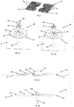
- Further advantages and features of the above induction coil assembly will be clear from the following detailed description, provided as a non limiting example, with reference to the attached drawings in which:
-
Fig. 1 is a perspective view of a induction coil assembly according to the invention; -
Fig. 2A and 2B are exploded perspective views of two embodiments of the invention; -
Figs. 3A and 3B are section views of the embodiments offigs. 2A and 2B ; -
Figs. 4 and 5 are perspective views, from the top and from the bottom respectively, of a central fix and turn element according to the invention. - With reference to
figs. 1-2B , acooktop assembly 10 includes asubstrate 12 containing at least onecoil assembly 14. Thesubstrate 12 is usually an aluminum plate which acts as a partition element and on which heating coils are mounted. As shown infigs. 2A and 2B , eachcoil assembly 14 is connected to thesubstrate 12 by a central fix and turnelement 16. The fix andturn element 16 extends through ashaped opening 22 defined by thesubstrate 12 and couples thecoil 18 and the coil wire support 20 to thesubstrate 12. The shaped opening presents a plurality of notches configured to cooperate with the fix and turnelement 16 for fastening the heating element. The plastic support usually comprises ferrite bars (not shown) for shielding the electromagnetic field. The fix andturn element 16 also functions as a receptacle for asensor 24A (fig. 2A ) or 24B (fig. 2B ) for thecoil assembly 14. Thesensor element 16, allowing the fix and turnelement 16 to be assembled with thesubstrate 12 separately from thecoil assembly 14. Further, the fix andturn element 16 can be configured to receive a variety of sensor holder or spring types as needed, for instance temperature sensors, depending on theparticular coil assembly 14. For example,Fig. 2A shows an embodiment wherein thesensor 24A includes acover 26.Fig. 2B shows a second embodiment wherein thesensor 24B includeswiring 28 extending down through thecoil 18,plastic support 20, andsubstrate 12, both of which can be used interchangeably with the fix andturn element 16. - Referring to
figs. 3A and 3B , the fix andturn element 16 is shown fully engaged with thesubstrate 12 to retain thecoil assembly 14. Because the fix andturn element 16 retains thecoil assembly 14 within the center thereof, a standard size and shape can be used to couplecoil assemblies 14 of various sizes and shapes to thesubstrate 12, eliminating the need for numerous connection options and allowing faster assembly of thecoil 14. - Referring now to
figs. 4 and 5 , a detailed view of the fix andturn element 16 is shown. The fix andturn element 16 includes atop portion 30 and abottom portion 32. Thetop portion 30 includes arecess 34 with astep portion 36 to engage with various embodiments of the above-described sensor holder or spring. The top portion defines anopening 38 that extends through the bottom portion, for example, to allow for wiring to reach the board sensor connector. Thebottom portion 32 includes a continuouslower surface 40 and a plurality offlanges 42 spaced vertically from thesurface 40 and radially from each other to pass through an opening in thesubstrate 12, when inserted in a first position, until thesurface 40 moves into contact withsubstrate 12. The fix andturn element 16 is then rotated into a second position wherein portions of thesubstrate 12 are captured between theflanges 42 andsurface 40. This fixed second position prevents the fix and turnelement 16 from detaching from thesubstrate 12, allowing it to hold a corresponding coil assembly in place.
Claims (8)
- An induction coil assembly (10) comprising a bottom plate (12) on which an induction heating element (14) is placed, the induction heating element (14) comprising a coil (18) mounted on a support (20) element, means being provided for fastening the heating element (14) to the bottom plate (12), characterized in that the means for fastening the heating element (14) to the bottom plate (12) comprise a central fix and turn element (16) configured to cooperate with a central aperture (22) of the bottom plate (12).
- An induction coil assembly according to claim 1, wherein the central fix and turn element (16) comprises radial flanges (42) adapted to cooperate, in a bayonet movement, with corresponding radial notches in the central aperture (22).
- An induction coil assembly according to claim 1 or 2, wherein the central fix and turn element (16) is made of polymeric material.
- An induction coil assembly according to any of the preceding claims, wherein the central fix and turn element (16) presents a seat for a sensor holder or spring or similar mechanical devices (26, 24A, 24B) designed to allocate a sensor.
- An induction coil assembly according to claim 4, wherein the sensor (24B) is a temperature sensor.
- An induction coil assembly according to claim 4 or 5, wherein the central fix and turn element (16) presents a central aperture (38) for passage of sensor wires (28).
- An induction coil assembly according to any of the preceding claims, wherein the support element (20) is made of polymeric material.
- An induction coil assembly according to any of the preceding claims, wherein the support element (20) is disc-shaped.
Priority Applications (1)
| Application Number | Priority Date | Filing Date | Title |
|---|---|---|---|
| EP18171367.8A EP3567987B1 (en) | 2018-05-08 | 2018-05-08 | Induction coil assembly |
Applications Claiming Priority (1)
| Application Number | Priority Date | Filing Date | Title |
|---|---|---|---|
| EP18171367.8A EP3567987B1 (en) | 2018-05-08 | 2018-05-08 | Induction coil assembly |
Publications (2)
| Publication Number | Publication Date |
|---|---|
| EP3567987A1 true EP3567987A1 (en) | 2019-11-13 |
| EP3567987B1 EP3567987B1 (en) | 2020-11-25 |
Family
ID=62143056
Family Applications (1)
| Application Number | Title | Priority Date | Filing Date |
|---|---|---|---|
| EP18171367.8A Active EP3567987B1 (en) | 2018-05-08 | 2018-05-08 | Induction coil assembly |
Country Status (1)
| Country | Link |
|---|---|
| EP (1) | EP3567987B1 (en) |
Citations (4)
| Publication number | Priority date | Publication date | Assignee | Title |
|---|---|---|---|---|
| US20100282737A1 (en) * | 2008-01-14 | 2010-11-11 | BSH Bosch und Siemens Hausgeräte GmbH | Induction heater comprising a circular inductor coil |
| WO2011138715A1 (en) * | 2010-05-06 | 2011-11-10 | BSH Bosch und Siemens Hausgeräte GmbH | Induction cook top comprising an inductor and a coil carrier |
| EP2632230A1 (en) * | 2012-02-24 | 2013-08-28 | Whirlpool Corporation | Induction heating device, cooking appliance using such device and method for assembly thereof |
| WO2015049602A1 (en) | 2013-10-03 | 2015-04-09 | BSH Bosch und Siemens Hausgeräte GmbH | Hob apparatus |
-
2018
- 2018-05-08 EP EP18171367.8A patent/EP3567987B1/en active Active
Patent Citations (4)
| Publication number | Priority date | Publication date | Assignee | Title |
|---|---|---|---|---|
| US20100282737A1 (en) * | 2008-01-14 | 2010-11-11 | BSH Bosch und Siemens Hausgeräte GmbH | Induction heater comprising a circular inductor coil |
| WO2011138715A1 (en) * | 2010-05-06 | 2011-11-10 | BSH Bosch und Siemens Hausgeräte GmbH | Induction cook top comprising an inductor and a coil carrier |
| EP2632230A1 (en) * | 2012-02-24 | 2013-08-28 | Whirlpool Corporation | Induction heating device, cooking appliance using such device and method for assembly thereof |
| WO2015049602A1 (en) | 2013-10-03 | 2015-04-09 | BSH Bosch und Siemens Hausgeräte GmbH | Hob apparatus |
Also Published As
| Publication number | Publication date |
|---|---|
| EP3567987B1 (en) | 2020-11-25 |
Similar Documents
| Publication | Publication Date | Title |
|---|---|---|
| EP3396235B1 (en) | Downlight fixing structure | |
| KR102554642B1 (en) | Cooking vessel comprising a sensor support | |
| US10229797B2 (en) | Push switch | |
| JP6429090B2 (en) | Induction heating cooker | |
| CN106974569B (en) | Method for realizing handle subassembly of cooking container | |
| US9270100B2 (en) | Fastening clip | |
| CN104981128B (en) | Fluid sensor or fluid valve electronic unit and fluid sensor unit or fluid valve cell | |
| JP6838477B2 (en) | Resin molded product | |
| EP3248898B1 (en) | Panel arrangement | |
| EP3567987B1 (en) | Induction coil assembly | |
| KR102720103B1 (en) | Contact devices, contact systems having such contact devices and methods for manufacturing such contact systems | |
| US7121835B2 (en) | Contact spring assembly, especially for an antenna amplifier | |
| CN211130725U (en) | Magnetic stripe installing support and cooking utensil | |
| EP3285009B1 (en) | Pressing element and induction hob comprising a pressing element | |
| US10476145B2 (en) | Radio frequency sensor module with mounting ears | |
| CN101657684B (en) | Cooking device, especially domestic cooking device | |
| US2467348A (en) | Electric heater | |
| US11004636B2 (en) | Electrical relay with mounting bracket | |
| US3499096A (en) | Container for electrical component | |
| JPH0197419A (en) | Cooker | |
| EP3413689B1 (en) | Connection element for connecting a heating energy generating element to a carrier element of a cooking hob | |
| EP4571194A1 (en) | Cooking hob and method for assembling a cooking hob | |
| CN109990025B (en) | Clamping component, spring assembly and steering wheel assembly | |
| EP3426001B1 (en) | Cooking hob | |
| CN212089209U (en) | Cooking utensil |
Legal Events
| Date | Code | Title | Description |
|---|---|---|---|
| PUAI | Public reference made under article 153(3) epc to a published international application that has entered the european phase |
Free format text: ORIGINAL CODE: 0009012 |
|
| STAA | Information on the status of an ep patent application or granted ep patent |
Free format text: STATUS: THE APPLICATION HAS BEEN PUBLISHED |
|
| AK | Designated contracting states |
Kind code of ref document: A1 Designated state(s): AL AT BE BG CH CY CZ DE DK EE ES FI FR GB GR HR HU IE IS IT LI LT LU LV MC MK MT NL NO PL PT RO RS SE SI SK SM TR |
|
| AX | Request for extension of the european patent |
Extension state: BA ME |
|
| STAA | Information on the status of an ep patent application or granted ep patent |
Free format text: STATUS: REQUEST FOR EXAMINATION WAS MADE |
|
| 17P | Request for examination filed |
Effective date: 20200601 |
|
| RBV | Designated contracting states (corrected) |
Designated state(s): AL AT BE BG CH CY CZ DE DK EE ES FI FR GB GR HR HU IE IS IT LI LT LU LV MC MK MT NL NO PL PT RO RS SE SI SK SM TR |
|
| RIC1 | Information provided on ipc code assigned before grant |
Ipc: H05B 6/12 20060101AFI20200728BHEP |
|
| GRAP | Despatch of communication of intention to grant a patent |
Free format text: ORIGINAL CODE: EPIDOSNIGR1 |
|
| STAA | Information on the status of an ep patent application or granted ep patent |
Free format text: STATUS: GRANT OF PATENT IS INTENDED |
|
| INTG | Intention to grant announced |
Effective date: 20200918 |
|
| GRAS | Grant fee paid |
Free format text: ORIGINAL CODE: EPIDOSNIGR3 |
|
| GRAA | (expected) grant |
Free format text: ORIGINAL CODE: 0009210 |
|
| STAA | Information on the status of an ep patent application or granted ep patent |
Free format text: STATUS: THE PATENT HAS BEEN GRANTED |
|
| AK | Designated contracting states |
Kind code of ref document: B1 Designated state(s): AL AT BE BG CH CY CZ DE DK EE ES FI FR GB GR HR HU IE IS IT LI LT LU LV MC MK MT NL NO PL PT RO RS SE SI SK SM TR |
|
| REG | Reference to a national code |
Ref country code: GB Ref legal event code: FG4D |
|
| REG | Reference to a national code |
Ref country code: CH Ref legal event code: EP |
|
| REG | Reference to a national code |
Ref country code: DE Ref legal event code: R096 Ref document number: 602018010009 Country of ref document: DE |
|
| REG | Reference to a national code |
Ref country code: AT Ref legal event code: REF Ref document number: 1339800 Country of ref document: AT Kind code of ref document: T Effective date: 20201215 |
|
| REG | Reference to a national code |
Ref country code: IE Ref legal event code: FG4D |
|
| REG | Reference to a national code |
Ref country code: AT Ref legal event code: MK05 Ref document number: 1339800 Country of ref document: AT Kind code of ref document: T Effective date: 20201125 |
|
| REG | Reference to a national code |
Ref country code: NL Ref legal event code: MP Effective date: 20201125 |
|
| PG25 | Lapsed in a contracting state [announced via postgrant information from national office to epo] |
Ref country code: GR Free format text: LAPSE BECAUSE OF FAILURE TO SUBMIT A TRANSLATION OF THE DESCRIPTION OR TO PAY THE FEE WITHIN THE PRESCRIBED TIME-LIMIT Effective date: 20210226 Ref country code: NO Free format text: LAPSE BECAUSE OF FAILURE TO SUBMIT A TRANSLATION OF THE DESCRIPTION OR TO PAY THE FEE WITHIN THE PRESCRIBED TIME-LIMIT Effective date: 20210225 Ref country code: RS Free format text: LAPSE BECAUSE OF FAILURE TO SUBMIT A TRANSLATION OF THE DESCRIPTION OR TO PAY THE FEE WITHIN THE PRESCRIBED TIME-LIMIT Effective date: 20201125 Ref country code: PT Free format text: LAPSE BECAUSE OF FAILURE TO SUBMIT A TRANSLATION OF THE DESCRIPTION OR TO PAY THE FEE WITHIN THE PRESCRIBED TIME-LIMIT Effective date: 20210325 Ref country code: FI Free format text: LAPSE BECAUSE OF FAILURE TO SUBMIT A TRANSLATION OF THE DESCRIPTION OR TO PAY THE FEE WITHIN THE PRESCRIBED TIME-LIMIT Effective date: 20201125 |
|
| PG25 | Lapsed in a contracting state [announced via postgrant information from national office to epo] |
Ref country code: AT Free format text: LAPSE BECAUSE OF FAILURE TO SUBMIT A TRANSLATION OF THE DESCRIPTION OR TO PAY THE FEE WITHIN THE PRESCRIBED TIME-LIMIT Effective date: 20201125 Ref country code: SE Free format text: LAPSE BECAUSE OF FAILURE TO SUBMIT A TRANSLATION OF THE DESCRIPTION OR TO PAY THE FEE WITHIN THE PRESCRIBED TIME-LIMIT Effective date: 20201125 Ref country code: PL Free format text: LAPSE BECAUSE OF FAILURE TO SUBMIT A TRANSLATION OF THE DESCRIPTION OR TO PAY THE FEE WITHIN THE PRESCRIBED TIME-LIMIT Effective date: 20201125 Ref country code: LV Free format text: LAPSE BECAUSE OF FAILURE TO SUBMIT A TRANSLATION OF THE DESCRIPTION OR TO PAY THE FEE WITHIN THE PRESCRIBED TIME-LIMIT Effective date: 20201125 Ref country code: IS Free format text: LAPSE BECAUSE OF FAILURE TO SUBMIT A TRANSLATION OF THE DESCRIPTION OR TO PAY THE FEE WITHIN THE PRESCRIBED TIME-LIMIT Effective date: 20210325 Ref country code: BG Free format text: LAPSE BECAUSE OF FAILURE TO SUBMIT A TRANSLATION OF THE DESCRIPTION OR TO PAY THE FEE WITHIN THE PRESCRIBED TIME-LIMIT Effective date: 20210225 |
|
| REG | Reference to a national code |
Ref country code: LT Ref legal event code: MG9D |
|
| PG25 | Lapsed in a contracting state [announced via postgrant information from national office to epo] |
Ref country code: HR Free format text: LAPSE BECAUSE OF FAILURE TO SUBMIT A TRANSLATION OF THE DESCRIPTION OR TO PAY THE FEE WITHIN THE PRESCRIBED TIME-LIMIT Effective date: 20201125 |
|
| PG25 | Lapsed in a contracting state [announced via postgrant information from national office to epo] |
Ref country code: CZ Free format text: LAPSE BECAUSE OF FAILURE TO SUBMIT A TRANSLATION OF THE DESCRIPTION OR TO PAY THE FEE WITHIN THE PRESCRIBED TIME-LIMIT Effective date: 20201125 Ref country code: EE Free format text: LAPSE BECAUSE OF FAILURE TO SUBMIT A TRANSLATION OF THE DESCRIPTION OR TO PAY THE FEE WITHIN THE PRESCRIBED TIME-LIMIT Effective date: 20201125 Ref country code: SM Free format text: LAPSE BECAUSE OF FAILURE TO SUBMIT A TRANSLATION OF THE DESCRIPTION OR TO PAY THE FEE WITHIN THE PRESCRIBED TIME-LIMIT Effective date: 20201125 Ref country code: SK Free format text: LAPSE BECAUSE OF FAILURE TO SUBMIT A TRANSLATION OF THE DESCRIPTION OR TO PAY THE FEE WITHIN THE PRESCRIBED TIME-LIMIT Effective date: 20201125 Ref country code: RO Free format text: LAPSE BECAUSE OF FAILURE TO SUBMIT A TRANSLATION OF THE DESCRIPTION OR TO PAY THE FEE WITHIN THE PRESCRIBED TIME-LIMIT Effective date: 20201125 Ref country code: LT Free format text: LAPSE BECAUSE OF FAILURE TO SUBMIT A TRANSLATION OF THE DESCRIPTION OR TO PAY THE FEE WITHIN THE PRESCRIBED TIME-LIMIT Effective date: 20201125 |
|
| REG | Reference to a national code |
Ref country code: DE Ref legal event code: R097 Ref document number: 602018010009 Country of ref document: DE |
|
| PG25 | Lapsed in a contracting state [announced via postgrant information from national office to epo] |
Ref country code: DK Free format text: LAPSE BECAUSE OF FAILURE TO SUBMIT A TRANSLATION OF THE DESCRIPTION OR TO PAY THE FEE WITHIN THE PRESCRIBED TIME-LIMIT Effective date: 20201125 |
|
| PLBE | No opposition filed within time limit |
Free format text: ORIGINAL CODE: 0009261 |
|
| STAA | Information on the status of an ep patent application or granted ep patent |
Free format text: STATUS: NO OPPOSITION FILED WITHIN TIME LIMIT |
|
| PG25 | Lapsed in a contracting state [announced via postgrant information from national office to epo] |
Ref country code: AL Free format text: LAPSE BECAUSE OF FAILURE TO SUBMIT A TRANSLATION OF THE DESCRIPTION OR TO PAY THE FEE WITHIN THE PRESCRIBED TIME-LIMIT Effective date: 20201125 Ref country code: NL Free format text: LAPSE BECAUSE OF FAILURE TO SUBMIT A TRANSLATION OF THE DESCRIPTION OR TO PAY THE FEE WITHIN THE PRESCRIBED TIME-LIMIT Effective date: 20201125 |
|
| 26N | No opposition filed |
Effective date: 20210826 |
|
| PG25 | Lapsed in a contracting state [announced via postgrant information from national office to epo] |
Ref country code: SI Free format text: LAPSE BECAUSE OF FAILURE TO SUBMIT A TRANSLATION OF THE DESCRIPTION OR TO PAY THE FEE WITHIN THE PRESCRIBED TIME-LIMIT Effective date: 20201125 |
|
| REG | Reference to a national code |
Ref country code: CH Ref legal event code: PL |
|
| PG25 | Lapsed in a contracting state [announced via postgrant information from national office to epo] |
Ref country code: LI Free format text: LAPSE BECAUSE OF NON-PAYMENT OF DUE FEES Effective date: 20210531 Ref country code: LU Free format text: LAPSE BECAUSE OF NON-PAYMENT OF DUE FEES Effective date: 20210508 Ref country code: MC Free format text: LAPSE BECAUSE OF FAILURE TO SUBMIT A TRANSLATION OF THE DESCRIPTION OR TO PAY THE FEE WITHIN THE PRESCRIBED TIME-LIMIT Effective date: 20201125 Ref country code: CH Free format text: LAPSE BECAUSE OF NON-PAYMENT OF DUE FEES Effective date: 20210531 Ref country code: ES Free format text: LAPSE BECAUSE OF FAILURE TO SUBMIT A TRANSLATION OF THE DESCRIPTION OR TO PAY THE FEE WITHIN THE PRESCRIBED TIME-LIMIT Effective date: 20201125 |
|
| REG | Reference to a national code |
Ref country code: BE Ref legal event code: MM Effective date: 20210531 |
|
| PG25 | Lapsed in a contracting state [announced via postgrant information from national office to epo] |
Ref country code: IE Free format text: LAPSE BECAUSE OF NON-PAYMENT OF DUE FEES Effective date: 20210508 |
|
| PG25 | Lapsed in a contracting state [announced via postgrant information from national office to epo] |
Ref country code: IS Free format text: LAPSE BECAUSE OF FAILURE TO SUBMIT A TRANSLATION OF THE DESCRIPTION OR TO PAY THE FEE WITHIN THE PRESCRIBED TIME-LIMIT Effective date: 20210325 |
|
| PG25 | Lapsed in a contracting state [announced via postgrant information from national office to epo] |
Ref country code: BE Free format text: LAPSE BECAUSE OF NON-PAYMENT OF DUE FEES Effective date: 20210531 |
|
| P01 | Opt-out of the competence of the unified patent court (upc) registered |
Effective date: 20230522 |
|
| PG25 | Lapsed in a contracting state [announced via postgrant information from national office to epo] |
Ref country code: CY Free format text: LAPSE BECAUSE OF FAILURE TO SUBMIT A TRANSLATION OF THE DESCRIPTION OR TO PAY THE FEE WITHIN THE PRESCRIBED TIME-LIMIT Effective date: 20201125 |
|
| PG25 | Lapsed in a contracting state [announced via postgrant information from national office to epo] |
Ref country code: HU Free format text: LAPSE BECAUSE OF FAILURE TO SUBMIT A TRANSLATION OF THE DESCRIPTION OR TO PAY THE FEE WITHIN THE PRESCRIBED TIME-LIMIT; INVALID AB INITIO Effective date: 20180508 |
|
| PG25 | Lapsed in a contracting state [announced via postgrant information from national office to epo] |
Ref country code: MK Free format text: LAPSE BECAUSE OF FAILURE TO SUBMIT A TRANSLATION OF THE DESCRIPTION OR TO PAY THE FEE WITHIN THE PRESCRIBED TIME-LIMIT Effective date: 20201125 |
|
| PG25 | Lapsed in a contracting state [announced via postgrant information from national office to epo] |
Ref country code: TR Free format text: LAPSE BECAUSE OF FAILURE TO SUBMIT A TRANSLATION OF THE DESCRIPTION OR TO PAY THE FEE WITHIN THE PRESCRIBED TIME-LIMIT Effective date: 20201125 |
|
| PG25 | Lapsed in a contracting state [announced via postgrant information from national office to epo] |
Ref country code: MT Free format text: LAPSE BECAUSE OF FAILURE TO SUBMIT A TRANSLATION OF THE DESCRIPTION OR TO PAY THE FEE WITHIN THE PRESCRIBED TIME-LIMIT Effective date: 20201125 |
|
| PGFP | Annual fee paid to national office [announced via postgrant information from national office to epo] |
Ref country code: DE Payment date: 20250528 Year of fee payment: 8 |
|
| PGFP | Annual fee paid to national office [announced via postgrant information from national office to epo] |
Ref country code: IT Payment date: 20250509 Year of fee payment: 8 |
|
| PGFP | Annual fee paid to national office [announced via postgrant information from national office to epo] |
Ref country code: FR Payment date: 20250526 Year of fee payment: 8 |
|
| PGFP | Annual fee paid to national office [announced via postgrant information from national office to epo] |
Ref country code: GB Payment date: 20260325 Year of fee payment: 9 |