EP3567499A1 - Drivetrain component simulation - Google Patents
Drivetrain component simulation Download PDFInfo
- Publication number
- EP3567499A1 EP3567499A1 EP18170995.7A EP18170995A EP3567499A1 EP 3567499 A1 EP3567499 A1 EP 3567499A1 EP 18170995 A EP18170995 A EP 18170995A EP 3567499 A1 EP3567499 A1 EP 3567499A1
- Authority
- EP
- European Patent Office
- Prior art keywords
- simulation
- drivetrain
- component
- request
- values
- Prior art date
- Legal status (The legal status is an assumption and is not a legal conclusion. Google has not performed a legal analysis and makes no representation as to the accuracy of the status listed.)
- Pending
Links
Images

Classifications
-
- G—PHYSICS
- G01—MEASURING; TESTING
- G01M—TESTING STATIC OR DYNAMIC BALANCE OF MACHINES OR STRUCTURES; TESTING OF STRUCTURES OR APPARATUS, NOT OTHERWISE PROVIDED FOR
- G01M13/00—Testing of machine parts
- G01M13/02—Gearings; Transmission mechanisms
- G01M13/025—Test-benches with rotational drive means and loading means; Load or drive simulation
-
- G—PHYSICS
- G06—COMPUTING OR CALCULATING; COUNTING
- G06F—ELECTRIC DIGITAL DATA PROCESSING
- G06F30/00—Computer-aided design [CAD]
- G06F30/10—Geometric CAD
- G06F30/15—Vehicle, aircraft or watercraft design
-
- B—PERFORMING OPERATIONS; TRANSPORTING
- B60—VEHICLES IN GENERAL
- B60W—CONJOINT CONTROL OF VEHICLE SUB-UNITS OF DIFFERENT TYPE OR DIFFERENT FUNCTION; CONTROL SYSTEMS SPECIALLY ADAPTED FOR HYBRID VEHICLES; ROAD VEHICLE DRIVE CONTROL SYSTEMS FOR PURPOSES NOT RELATED TO THE CONTROL OF A PARTICULAR SUB-UNIT
- B60W30/00—Purposes of road vehicle drive control systems not related to the control of a particular sub-unit, e.g. of systems using conjoint control of vehicle sub-units
- B60W30/18—Propelling the vehicle
- B60W30/188—Controlling power parameters of the driveline, e.g. determining the required power
-
- B—PERFORMING OPERATIONS; TRANSPORTING
- B60—VEHICLES IN GENERAL
- B60W—CONJOINT CONTROL OF VEHICLE SUB-UNITS OF DIFFERENT TYPE OR DIFFERENT FUNCTION; CONTROL SYSTEMS SPECIALLY ADAPTED FOR HYBRID VEHICLES; ROAD VEHICLE DRIVE CONTROL SYSTEMS FOR PURPOSES NOT RELATED TO THE CONTROL OF A PARTICULAR SUB-UNIT
- B60W30/00—Purposes of road vehicle drive control systems not related to the control of a particular sub-unit, e.g. of systems using conjoint control of vehicle sub-units
- B60W30/18—Propelling the vehicle
- B60W30/20—Reducing vibrations in the driveline
-
- G—PHYSICS
- G06—COMPUTING OR CALCULATING; COUNTING
- G06F—ELECTRIC DIGITAL DATA PROCESSING
- G06F30/00—Computer-aided design [CAD]
- G06F30/20—Design optimisation, verification or simulation
-
- G—PHYSICS
- G06—COMPUTING OR CALCULATING; COUNTING
- G06F—ELECTRIC DIGITAL DATA PROCESSING
- G06F2111/00—Details relating to CAD techniques
- G06F2111/20—Configuration CAD, e.g. designing by assembling or positioning modules selected from libraries of predesigned modules
-
- Y—GENERAL TAGGING OF NEW TECHNOLOGICAL DEVELOPMENTS; GENERAL TAGGING OF CROSS-SECTIONAL TECHNOLOGIES SPANNING OVER SEVERAL SECTIONS OF THE IPC; TECHNICAL SUBJECTS COVERED BY FORMER USPC CROSS-REFERENCE ART COLLECTIONS [XRACs] AND DIGESTS
- Y02—TECHNOLOGIES OR APPLICATIONS FOR MITIGATION OR ADAPTATION AGAINST CLIMATE CHANGE
- Y02T—CLIMATE CHANGE MITIGATION TECHNOLOGIES RELATED TO TRANSPORTATION
- Y02T90/00—Enabling technologies or technologies with a potential or indirect contribution to GHG emissions mitigation
Definitions
- the present invention relates to drivetrains, and more precisely simulating one or more drivetrain components.
- An object of the present invention is to provide a near real time simulation results for drivetrains or one or more drivetrain components.
- the object of the invention is achieved by a method, equipment and a computer program product which are characterized by what is stated in the independent claims.
- the preferred embodiments of the invention are disclosed in the dependent claims.
- a general aspect of the invention uses logically centralized environment, simulation equipment, which receives as input identification information of a drivetrain or its component and one or more operation conditions, and based on them retrieves required information, such as information on one or more component types and one or more related values, performs required simulation and outputs the simulation result.
- required information such as information on one or more component types and one or more related values
- the present invention is applicable to any system or equipment that is configured or configurable to simulate drivetrain and/or its components. Different embodiments and examples are described below using single units and computing device and memory, without restricting the embodiments/examples to such a solution.
- Concepts called cloud computing and virtualization may be used as well.
- the virtualization may allow a single physical computing device to host one or more instances of virtual machines that appear and operate as independent computing devices, so that a single physical computing device can create, maintain, delete, or otherwise manage virtual machines in a dynamic manner. It is also possible that device operations will be distributed among a plurality of servers, nodes, devices or hosts. In cloud computing network devices, computing devices and/or storage devices provide shared resources.
- SDN Software-Defined Networking
- Figure 1 is a simplified system architecture only showing some devices, apparatuses and functional entities, all being logical units whose implementation and/or number may differ from what is shown.
- the connections shown in Figure 1 are logical connections; the actual physical connections may be different. It is apparent to a person skilled in the art that the system comprises any number of shown elements, other equipment, other functions and structures that are not illustrated. They, as well as the protocols used, are well known by persons skilled in the art and are irrelevant to the actual invention. Therefore, they need not to be discussed in more detail here.
- the system 100 comprises one or more industrial sites 101 (only one illustrated in Figure 1 ) connected over one or more networks 102 to a service center 103.
- the system 100 may implement a concept called Internet of Things, Services and People (IoTSP), in which the industrial site 101 may be configured to act as an edge, and the service center 103 may be configured as a global cloud level 101 forming a level for central management, for example.
- IoTSP Internet of Things, Services and People
- sensors measuring and/or collecting different information may be configured to send the data they collect, to the service center.
- any other implementation including those not utilizing IoTSP, may be used as well.
- the industrial site 101 comprises one or more user apparatuses 110 (only one illustrated in Figure 1 ) and one or more drivetrains 120 (only one illustrated in Figure 1 ).
- the user apparatus 110 is a computing device comprising different user interfaces, such as touch screens, other type of displays, and keypads for example.
- the user apparatus 110 may be a local service desk, or a factory level service desk, etc., such as a work station or a server, like a cloud server or a grid server.
- the user apparatus may as well be a remote user's mobile user apparatus comprising, for example, a smartphone application for commissioning, servicing and/or use of drivetrain 120, for example.
- the user apparatus 110 may be connected to the drivetrain over a wireless connection, including short range wireless communication, such as Bluetooth or near field communication, just to name some examples without limiting to those, and/or over a wired connection. However, the details of the connection bears no significance and are therefore not described in detail herein.
- the drivetrain 120 comprises typically several components 120m, 120n, 120x that together form the drivetrain.
- components include a motor, a pump, a frequency convertor, a transformer, a gearbox, an actuator, and a compressor.
- a component may comprise one or more components, although not illustrated in Figure 1 .
- a motor may comprise a rotor, a shaft, bearings, a stator, windings, and a protective relay.
- the drivetrain 120 comprises one or more interfaces (not depicted in Figure) via which parameters of the drivetrain 120, i.e. its components 120m, 120n, 120x may be adjusted or acquired, and/or the functions of the drivetrain 120 otherwise controlled, locally via the user apparatus 120 and/or directly by the service center 103.
- the one or more networks 102 may comprise one or more wireless networks, wherein a wireless network may be based on any mobile system, such as GSM, GPRS, LTE, 4G, 5G and beyond, or a wireless local area network, such as Wi-Fi. Further, the one or more networks 102 may comprise one or more fixed networks.
- the service center 103 or corresponding equipment comprises for simulation services to the drivetrains simulation equipment 130 providing a simulation platform.
- the simulation equipment 130 may be any equipment or a computing device comprising memory, or a sub-system (simulation system), comprising computing devices that are configured to appear as one logical simulation equipment for user apparatuses, for example.
- the simulation equipment 130 comprises a simulation service unit (s-s-u) 131, which provides an application programming interface to drivetrain simulations. Further, the simulation equipment comprises, at least for simulation purposes, in a database 132 (or memory) information 132-1 associating identification information of a drivetrain to its component information, and different model data 132-2. Naturally the information may be used for other purposes and the memory may contain other information, for example data collected from drivetrains. Further, in the illustrated example, the simulation equipment 130 comprises different analytics tools 133 and different simulation tools 134. There are no restrictions relating to analytics tools 133 and simulation tools 134, any known or future tool may be used. Further, the internal functionality of the tools bears no significance to disclosed solutions, and therefore the tools are not described in more detail herein.
- the database 132 refers herein to a combination of a data storage and a data management system.
- the data storage may be any kind of conventional or future data repository, including distributed and centralized storing of data, a cloud-based storage in a cloud environment, managed by any suitable management system.
- the implementation of the data storage, the manner how data is stored, retrieved and updated are irrelevant to the invention, and therefore not described in detail here.
- the database 132 comprises for the simulation service the information 132-1 associating identification information of a drivetrain to its component information.
- the component information may comprise information on component types for components associated with the identification information.
- component type is used as a synonym to information on component type.
- one or more values may be given for component types component type specifically, as part of the component information, or as a separate information. For example, based on the component type, one or more of the values may be retrievable from model information 132-2.
- information generated by the one or more analytics tool may be associated as value information for the component types or components or drivetrains by means of the identification information.
- the serial number of the drivetrain can be used for determining motor type, pump type, etc., as will be explained in more detail below.
- the model data may comprise for each drivetrain, or drivetrain type, detailed information, such as information on manufacturer, size information, software version of installed software, if any, and design data generated.
- a non-limiting list of examples of the design data includes component dimensions and material properties.
- Design data may have been generated, for example, by a computer aided design (CAD) during designing the drivetrain, and/or by ERP (Enterprise Resource Planning.
- CAD computer aided design
- ERP Enterprise Resource Planning.
- a rotating drivetrain is designed with tools based on machine models, such as lumped parameter models, 2 dimensional/3 dimensional finite element analysis (FEA) models as electromagnetical models, computational fluid dynamics (CFD) models, and mechanical models, wherein the models may be coupled models with supply and/or load.
- machine models such as lumped parameter models, 2 dimensional/3 dimensional finite element analysis (FEA) models as electromagnetical models, computational fluid dynamics (CFD) models, and mechanical models, wherein the models may be coupled models with supply and/or load.
- FEA finite element analysis
- CFD computational fluid dynamics
- model data may comprise corresponding information on components and/or component types.
- Figure 2 illustrates an exemplary functionality of the simulation equipment, or more precisely, the functionality of the simulation service unit.
- a request relating to a drivetrain is received in step 201.
- the request may be addressed to a function to be performed, or the function may be included to be part of the request.
- the function may be indicated by means of a purpose of the simulation, such as "provide commissioning settings", "provide temperature inside a motor", for example.
- the received request contains one or more operation conditions and identification information identifying one or more components of the drivetrain.
- the identification information may be an identifier of the drivetrain, such as a serial number, for example.
- step 202 component information, which indicates for each component in the drivetrain, a component type, is retrieved in step 202 based on the identification information received in step 201.
- one or more values are retrieved in step 203, based on the one or more component types and the received one or more operation conditions.
- the values may be retrieved from model data, and/or the component information may comprise one or more of the values.
- the analysis and/or measurement data may be maintained in, and retrieved from a product data management system, for example.
- the retrieved values are then used as an input to calculate in step 204 a simulation result for the drivetrain and/or for one or more of components.
- a simulation result for the drivetrain and/or for one or more of components.
- one or more of the operation conditions may be used as an input to calculate in step 204 the simulation result, which is then outputted in step 205.
- the outputted value may then be used for the indicated purpose, as will be described below with further examples.
- calculating a simulation result may contain a plurality of successive simulations or parallel simulations. For example, for each component a separate simulation tool may be used. In another example, using at least the component type, possible also the one or more operation conditions, a proper simulation tool for calculations may be selected.
- a digital twin for the drivetrain may be created on a fly for the specific need, and there is no need to determine a digital twin for each drivetrain.
- the simulation equipment is illustrated as a separate server, that comprises the simulation service unit, and a database, that comprises the component information and model data, and may comprise also other data.
- Figure 3 illustrate an example of functionalities implemented using machine-to-machine information exchange, i.e. without any user, or user apparatus, involvement, whereas in the example of Figure 4 , a user is involved, at least in monitoring the results.
- a drivetrain sends message 3-1 to the server, the message comprising one or more operation conditions, and identification information.
- the message may relate to troubleshooting. For example, a temperature of a running motor in the drivetrain may have been too high, and a protective relay shuts the motor down, and that causes the drivetrain to send in message the operation conditions, like the current of the motor was A, running time one hour, temperature exceeded, "how to adjust parameters", and the identification data may be an identifier of the drivetrain (and/ or the motor, and/ or the protective relay).
- the server receives message 3-1, and detects in point 3-2 the identifier and the purpose what for simulation is requested, retrieves (messages 3-3) component types of the motor and the protective relay, possible also from other components, and one or more values, and then performs the simulation in point 3-4.
- the components may be simulated separately and/or as one or more aggregates of the components, as explained above with Figure 2 . Then the simulation results are outputted by sending new parameter values in message 3-5 to the drivetrain as a response to the request send in message 3-1.
- the new parameter values received by the drivetrain in the response are set in point 3-6, and the protective relay allows the drivetrain to start to operate again.
- an intelligent protective relay is provided without detailed data on the motor being disposed (delivered) to the drivetrain.
- any other troubleshooting may be performed correspondingly, when the need arises.
- message 3-1 with a request indicating a question "a anomaly/malfunction was detected, is there something to do differently?" is sent with the drivetrain identifier and operation parameters.
- the request may be sent without operation parameters, in which case measurement values may be used.
- the fault conditions that need simulation result will be simulated, using actual available inputs, and there is no need to pre-simulate different electrical and mechanical fault conditions.
- message 3-1 may comprise the identifier, and indicate "not commissioned", for example by having no operation conditions (empty instead of operation conditions), and a request for commissioning parameters is sent in message 3-1, and commissioning parameters are received in message 3-5, and setting the parameters in point 3-6 commissions the drivetrain.
- a mere identifier such as a serial number of the drivetrain
- the solution may be used for testing of the drivetrain, for example to determine some critical values, such as to calculate bearing critical values.
- operation conditions may include values for one or more of the following: speed range, radial load, housing ambient temperature and housing ambient air velocity.
- the disclosed solutions may be used also for optimizing the parameter values component-specifically.
- a frequency converter may tune itself to operate with a pump with the above disclosed machine-to-machine communication. It is also possible to optimize parameter values to obtain a specific target, such as a maximum power transfer ratio. In such a case, the result, based on optimizing parameter values for each component, will allow optimizing the whole drivetrain, to provide the best possible power transfer ration, without any need to have a table or a database dedicated for that purpose.
- the example of Figure 4 differs from the example illustrated in Figure 3 in that respect that a user apparatus is involved.
- the user apparatus may comprise a remote assistant tool, or any corresponding tool, that may have been configured to display, for example, a plant in a gradual mode: for example first different portions of the plant, and when a drying plant1, for example, is selected, then a motor is displayed, when the motor is selected, different information, including simulation results, may be displayed.
- the drivetrain, and/or its components may be equipped with sensors that transmit measurement data to cloud, for example, in which case there is no need to retrieve the measurement data.
- sensors that transmit measurement data to cloud, for example, in which case there is no need to retrieve the measurement data.
- time stamps for example, may be used to match one or more pieces of the measurement data to operation conditions.
- the user apparatus sends message 4-1 comprising at least the operational parameters and the identifier to the server.
- the server detects in point 4-2 the identifier and the purpose what for simulation is requested.
- message 4-2 a message that comprises an identifier of the drivetrain, stator's current power and temperature, and a request for rotor's temperature (which cannot be measured)
- the server retrieves (messages 4-3) component types and one or more values, and then performs the simulation in point 4-4.
- the result is a temperature that cannot be measured from the physical component.
- the simulation result is outputted by sending the temperature in message 4-5 to the user apparatus as a response to the request send in message 4-1.
- the user apparatus displays in point 4-6 the received temperature. It may be displayed with actual temperature measurements results of other components, and the request 4-1 may be sent at a certain interval, for example the same used in actual measurements.
- the simulation result outputted via the display may show an inner view of the drivetrain, or its component, like a motor, the inner view comprising value that cannot be measured from the real life physical drivetrain.
- the simulation result may be "if you run the drivetrain, or motor, in the way it is currently run, the time between two consecutive lubrications will be x days but if you run like using the parameters given herein, the time will be x+a days.”, and then the user of the user apparatus may cause the parameters to be updated.
- the simulation result may provide calculation of actual loads on critical components, for example bearings, lifespan prediction of critical components based on actual values, specification of monitoring requirements and maintenance intervals, setting of alarm and trip limits, fast data analysis and feedback from successful commissioning by comparing commissioning values with measured values and simulated values, when values cannot be measured, shaft voltage estimation, motor noise and vibration spectrum estimation, etc.
- the techniques and methods described herein may be implemented by various means so that equipment/a device/an apparatus configured to support at least partly on what is disclosed above with any of Figures 1 to 4 , including implementing one or more functions/operations of a corresponding device/equipment described above with an embodiment/example, for example by means of any of Figures 1 to 4 , comprises not only prior art means, but also means for implementing the one or more functions/operations of a corresponding functionality described with an embodiment/example, for example by means of any of Figures 1 to 4 , and the device/equipment may comprise separate means for each separate function/operation, or means may be configured to perform two or more functions/operations.
- one or more of the means and/or the simulation service unit described above may be implemented in hardware (one or more devices), firmware (one or more devices), software (one or more modules), or combinations thereof.
- the device (s) or apparatus (es) or equipment of embodiments/examples may be implemented within one or more application-specific integrated circuits (ASICs), digital signal processors (DSPs), digital signal processing devices (DSPDs), programmable logic devices (PLDs), field programmable gate arrays (FPGAs), processors, controllers, micro-controllers, microprocessors, logic gates, other electronic units designed to perform the functions described herein by means of Figures 1 to 4 , or a combination thereof.
- ASICs application-specific integrated circuits
- DSPs digital signal processors
- DSPDs digital signal processing devices
- PLDs programmable logic devices
- FPGAs field programmable gate arrays
- processors controllers, micro-controllers, microprocessors, logic gates, other electronic units designed to perform the functions described
- the implementation can be carried out through modules of at least one chipset (e.g. procedures, functions, and so on) that perform the functions described herein.
- the software codes may be stored in a memory unit and executed by processors.
- the memory unit may be implemented within the processor or externally to the processor. In the latter case, it can be communicatively coupled to the processor via various means, as is known in the art.
- the components described herein may be rearranged and/or complemented by additional components in order to facilitate the achievements of the various aspects, etc., described with regard thereto, and they are not limited to the precise configurations set forth in the given figures, as will be appreciated by one skilled in the art.
- Figure 5 is a simplified block diagram illustrating some units for equipment 500 configured to provide the simulation equipment, or a corresponding computing device, comprising at least one or more simulation service units, or corresponding units and sub-units, described above with Figures 1 to 4 or corresponding functionality or some of the corresponding functionality if functionalities are distributed in the future.
- the equipment comprises one or more interfaces (IF) 501 for receiving and/or transmitting information from or to other devices, and possibly from or to a user, one or more processors 502 configured to implement the simulation service unit described above with Figures 1 to 4 , or at least part of corresponding functionality as a sub-unit functionality if distributed scenario is implemented, with corresponding algorithms 503, and one or more memories 504 usable for storing at least computer program code required for the one or more simulation service units or for one or more corresponding units or sub-units, i.e. the algorithms for implementing the functionality.
- the memory 804 is also usable for storing other possible information, such as the component information and/or the models and/or computer program code required for implementing different simulation and/or analytics tools, for example.
- the simulation equipment configured to provide equipment, or a device/apparatus configured to provide one or more the corresponding functionalities described above with Figures 1 to 4
- a computing equipment may be any apparatus or device or equipment or node configured to perform one or more of the corresponding functionalities described above with an embodiment/example/implementation, and it may be configured to perform functionalities from different embodiments/examples/implementations.
- the one or simulation service units, as well as corresponding units and sub-units may be separate units, even located in another physical apparatus, the distributed physical apparatuses forming one logical equipment providing the functionality, or integrated to another unit in the same equipment.
- the equipment configured to provide the simulation equipment, or a device configured to provide one or more corresponding functionalities may generally include one or more processors, controllers, control units, micro-controllers, or the like connected to one or more memories and to various interfaces of the equipment.
- a processor is a central processing unit, but the processor may be an additional operation processor.
- Each or some or one of the units/sub-units and/or algorithms described herein may be configured as a computer or a processor, or a microprocessor, such as a single-chip computer element, or as a chipset, including at least a memory for providing storage area used for arithmetic operation and an operation processor for executing the arithmetic operation.
- Each or some or one of the units/sub-units and/or algorithms described above may comprise one or more computer processors, application-specific integrated circuits (ASIC), digital signal processors (DSP), digital signal processing devices (DSPD), programmable logic devices (PLD), field-programmable gate arrays (FPGA), logic gates and/or other hardware components that have been programmed and/or will be programmed by downloading computer program code (one or more algorithms) in such a way to carry out one or more functions of one or more embodiments/implementations/examples.
- ASIC application-specific integrated circuits
- DSP digital signal processors
- DSPD digital signal processing devices
- PLD programmable logic devices
- FPGA field-programmable gate arrays
- logic gates and/or other hardware components that have been programmed and/or will be programmed by downloading computer program code (one or more algorithms) in such a way to carry out one or more functions of one or more embodiments/implementations/examples.
- An embodiment provides a computer program embodied on any client-readable distribution/data storage medium or memory unit(s) or article(s) of manufacture, comprising program instructions executable by one or more processors/computers, which instructions, when loaded into a device, constitute the simulation service unit, or any sub-unit, or corresponding application programming interface.
- Programs also called program products, including software routines, program snippets constituting "program libraries", applets and macros, can be stored in any medium and may be downloaded into an apparatus.
- each or some or one of the units/sub-units and/or the algorithms described above may be an element that comprises one or more arithmetic logic units, a number of special registers and control circuits.
- the equipment configured to provide the simulation equipment, or a device configured to provide one or more of the corresponding functionalities described above with Figures 1 to 4 may generally include volatile and/or non-volatile memory, for example EEPROM, ROM, PROM, RAM, DRAM, SRAM, double floating-gate field effect transistor, firmware, programmable logic, etc. and typically store content, data, or the like.
- volatile and/or non-volatile memory for example EEPROM, ROM, PROM, RAM, DRAM, SRAM, double floating-gate field effect transistor, firmware, programmable logic, etc.
- the memory or memories may be of any type (different from each other), have any possible storage structure and, if required, being managed by any database management system.
- the memory may be any computer-usable non-transitory medium within the processor/equipment or external to the processor/equipment, in which case it can be communicatively coupled to the processor/equipment via various means as is known in the art.
- Examples of an external memory include a removable memory detachably connected to the apparatus, a distributed database and a cloud server.
- the memory may also store computer program code such as software applications (for example, for one or more of the units/sub-units/algorithms) or operating systems, information, data, content, or the like for the processor to perform steps associated with operation of the equipment in accordance with examples/embodiments.
Landscapes
- Engineering & Computer Science (AREA)
- Physics & Mathematics (AREA)
- Theoretical Computer Science (AREA)
- Geometry (AREA)
- General Physics & Mathematics (AREA)
- Automation & Control Theory (AREA)
- General Engineering & Computer Science (AREA)
- Computer Hardware Design (AREA)
- Evolutionary Computation (AREA)
- Transportation (AREA)
- Mechanical Engineering (AREA)
- Aviation & Aerospace Engineering (AREA)
- Computational Mathematics (AREA)
- Mathematical Analysis (AREA)
- Mathematical Optimization (AREA)
- Pure & Applied Mathematics (AREA)
- Testing And Monitoring For Control Systems (AREA)
Abstract
Description
- The present invention relates to drivetrains, and more precisely simulating one or more drivetrain components.
- It is known that designing a drivetrain is a highly complex engineering task. Further, drivetrain optimisation is performed manually or based on pre-calculated parameters, and although simulation methods are improved, the simulations are still pre-simulations for certain operation points and/or pre-simulating certain fault conditions. Hence, there is a need for a mechanism enabling nearly real-time simulation of drivetrains and/or drivetrain components for a variety of purposes.
- SUMMARY An object of the present invention is to provide a near real time simulation results for drivetrains or one or more drivetrain components. The object of the invention is achieved by a method, equipment and a computer program product which are characterized by what is stated in the independent claims. The preferred embodiments of the invention are disclosed in the dependent claims.
- A general aspect of the invention uses logically centralized environment, simulation equipment, which receives as input identification information of a drivetrain or its component and one or more operation conditions, and based on them retrieves required information, such as information on one or more component types and one or more related values, performs required simulation and outputs the simulation result. This provides a mechanism with which it is, for example, possible to provide the required simulation results without the requester inputting detailed information on the drivetrain or its component.
- In the following, exemplary embodiments will be described in greater detail with reference to accompanying drawings, in which
-
Figure 1 shows simplified architecture of a system and a block diagram of exemplified equipment; -
Figure 2 is a flow chart illustrating functionalities according to an example; -
Figures 3 and 4 illustrate examples of information exchange and functionalities; and -
Figure 5 is a schematic block diagram. - The following embodiments are exemplary. Although the specification may refer to "an", "one", or "some" embodiment(s) in several locations, this does not necessarily mean that each such reference is to the same embodiment(s), or that the feature only applies to a single embodiment. Single features of different embodiments may also be combined to provide other embodiments.
- The present invention is applicable to any system or equipment that is configured or configurable to simulate drivetrain and/or its components. Different embodiments and examples are described below using single units and computing device and memory, without restricting the embodiments/examples to such a solution. Concepts called cloud computing and virtualization may be used as well. The virtualization may allow a single physical computing device to host one or more instances of virtual machines that appear and operate as independent computing devices, so that a single physical computing device can create, maintain, delete, or otherwise manage virtual machines in a dynamic manner. It is also possible that device operations will be distributed among a plurality of servers, nodes, devices or hosts. In cloud computing network devices, computing devices and/or storage devices provide shared resources. Some other technology advancements, such as Software-Defined Networking (SDN), may cause one or more of the functionalities described below to be migrated to any corresponding abstraction or apparatus or device. Therefore, all words and expressions should be interpreted broadly, and they are intended to illustrate, not to restrict, the embodiment.
- A general exemplary architecture of a system is illustrated in
Figure 1. Figure 1 is a simplified system architecture only showing some devices, apparatuses and functional entities, all being logical units whose implementation and/or number may differ from what is shown. The connections shown inFigure 1 are logical connections; the actual physical connections may be different. It is apparent to a person skilled in the art that the system comprises any number of shown elements, other equipment, other functions and structures that are not illustrated. They, as well as the protocols used, are well known by persons skilled in the art and are irrelevant to the actual invention. Therefore, they need not to be discussed in more detail here. - In the embodiment illustrated in
Figure 1 , thesystem 100 comprises one or more industrial sites 101 (only one illustrated inFigure 1 ) connected over one ormore networks 102 to aservice center 103. Thesystem 100 may implement a concept called Internet of Things, Services and People (IoTSP), in which theindustrial site 101 may be configured to act as an edge, and theservice center 103 may be configured as aglobal cloud level 101 forming a level for central management, for example. In such an implementation, sensors measuring and/or collecting different information may be configured to send the data they collect, to the service center. However, any other implementation, including those not utilizing IoTSP, may be used as well. - In the illustrated example the
industrial site 101 comprises one or more user apparatuses 110 (only one illustrated inFigure 1 ) and one or more drivetrains 120 (only one illustrated inFigure 1 ). - The
user apparatus 110 is a computing device comprising different user interfaces, such as touch screens, other type of displays, and keypads for example. Theuser apparatus 110 may be a local service desk, or a factory level service desk, etc., such as a work station or a server, like a cloud server or a grid server. The user apparatus may as well be a remote user's mobile user apparatus comprising, for example, a smartphone application for commissioning, servicing and/or use ofdrivetrain 120, for example. Theuser apparatus 110 may be connected to the drivetrain over a wireless connection, including short range wireless communication, such as Bluetooth or near field communication, just to name some examples without limiting to those, and/or over a wired connection. However, the details of the connection bears no significance and are therefore not described in detail herein. - The
drivetrain 120 comprises typicallyseveral components Figure 1 . For example, a motor may comprise a rotor, a shaft, bearings, a stator, windings, and a protective relay. Thedrivetrain 120 comprises one or more interfaces (not depicted in Figure) via which parameters of thedrivetrain 120, i.e. itscomponents drivetrain 120 otherwise controlled, locally via theuser apparatus 120 and/or directly by theservice center 103. - The one or more networks 102 (communications networks) may comprise one or more wireless networks, wherein a wireless network may be based on any mobile system, such as GSM, GPRS, LTE, 4G, 5G and beyond, or a wireless local area network, such as Wi-Fi. Further, the one or
more networks 102 may comprise one or more fixed networks. - The
service center 103, or corresponding equipment comprises for simulation services to thedrivetrains simulation equipment 130 providing a simulation platform. Thesimulation equipment 130 may be any equipment or a computing device comprising memory, or a sub-system (simulation system), comprising computing devices that are configured to appear as one logical simulation equipment for user apparatuses, for example. - In the illustrated example, the
simulation equipment 130 comprises a simulation service unit (s-s-u) 131, which provides an application programming interface to drivetrain simulations. Further, the simulation equipment comprises, at least for simulation purposes, in a database 132 (or memory) information 132-1 associating identification information of a drivetrain to its component information, and different model data 132-2. Naturally the information may be used for other purposes and the memory may contain other information, for example data collected from drivetrains. Further, in the illustrated example, thesimulation equipment 130 comprisesdifferent analytics tools 133 and different simulation tools 134. There are no restrictions relating toanalytics tools 133 and simulation tools 134, any known or future tool may be used. Further, the internal functionality of the tools bears no significance to disclosed solutions, and therefore the tools are not described in more detail herein. - The
database 132 refers herein to a combination of a data storage and a data management system. The data storage may be any kind of conventional or future data repository, including distributed and centralized storing of data, a cloud-based storage in a cloud environment, managed by any suitable management system. The implementation of the data storage, the manner how data is stored, retrieved and updated are irrelevant to the invention, and therefore not described in detail here. - As said above, the
database 132 comprises for the simulation service the information 132-1 associating identification information of a drivetrain to its component information. The component information may comprise information on component types for components associated with the identification information. Below term "component type" is used as a synonym to information on component type. Further, one or more values may be given for component types component type specifically, as part of the component information, or as a separate information. For example, based on the component type, one or more of the values may be retrievable from model information 132-2. In addition, information generated by the one or more analytics tool may be associated as value information for the component types or components or drivetrains by means of the identification information. Using a serial number (SN) as an example of identification information, the serial number of the drivetrain can be used for determining motor type, pump type, etc., as will be explained in more detail below. The model data may comprise for each drivetrain, or drivetrain type, detailed information, such as information on manufacturer, size information, software version of installed software, if any, and design data generated. A non-limiting list of examples of the design data includes component dimensions and material properties. Design data may have been generated, for example, by a computer aided design (CAD) during designing the drivetrain, and/or by ERP (Enterprise Resource Planning. For example, a rotating drivetrain is designed with tools based on machine models, such as lumped parameter models, 2 dimensional/3 dimensional finite element analysis (FEA) models as electromagnetical models, computational fluid dynamics (CFD) models, and mechanical models, wherein the models may be coupled models with supply and/or load. Naturally, the model data may comprise corresponding information on components and/or component types. -
Figure 2 illustrates an exemplary functionality of the simulation equipment, or more precisely, the functionality of the simulation service unit. - Referring to
Figure 2 , a request relating to a drivetrain is received instep 201. Depending on implementation, the request may be addressed to a function to be performed, or the function may be included to be part of the request. The function may be indicated by means of a purpose of the simulation, such as "provide commissioning settings", "provide temperature inside a motor", for example. Regardless of what the function (purpose) is and how it is indicated with the request, the received request contains one or more operation conditions and identification information identifying one or more components of the drivetrain. The identification information may be an identifier of the drivetrain, such as a serial number, for example. By means of the serial number of a drivetrain it is easy to determine components belonging to the drivetrain, and identification information of a component, if the request is for a simulation result for a component is not needed. However, if the identification information identifies the component, that identification information can naturally be used. Then instep 202 component information, which indicates for each component in the drivetrain, a component type, is retrieved instep 202 based on the identification information received instep 201. - Once the one or more component types are known, one or more values are retrieved in
step 203, based on the one or more component types and the received one or more operation conditions. The values may be retrieved from model data, and/or the component information may comprise one or more of the values. Naturally, if there are analysis and/or measurement data available, one or more values may be retrieved therefrom. The analysis and/or the measurement data may be maintained in, and retrieved from a product data management system, for example. - The retrieved values are then used as an input to calculate in step 204 a simulation result for the drivetrain and/or for one or more of components. Naturally, one or more of the operation conditions may be used as an input to calculate in
step 204 the simulation result, which is then outputted instep 205. The outputted value may then be used for the indicated purpose, as will be described below with further examples. - It should be appreciated that calculating a simulation result may contain a plurality of successive simulations or parallel simulations. For example, for each component a separate simulation tool may be used. In another example, using at least the component type, possible also the one or more operation conditions, a proper simulation tool for calculations may be selected.
- As is evident from the above, a digital twin for the drivetrain may be created on a fly for the specific need, and there is no need to determine a digital twin for each drivetrain.
- Information exchanges illustrated in
Figures 3 and 4 provides different use examples. In the example, the simulation equipment is illustrated as a separate server, that comprises the simulation service unit, and a database, that comprises the component information and model data, and may comprise also other data. -
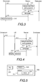
Figure 3 illustrate an example of functionalities implemented using machine-to-machine information exchange, i.e. without any user, or user apparatus, involvement, whereas in the example ofFigure 4 , a user is involved, at least in monitoring the results. - Referring to
Figure 3 , a drivetrain sends message 3-1 to the server, the message comprising one or more operation conditions, and identification information. The message may relate to troubleshooting. For example, a temperature of a running motor in the drivetrain may have been too high, and a protective relay shuts the motor down, and that causes the drivetrain to send in message the operation conditions, like the current of the motor was A, running time one hour, temperature exceeded, "how to adjust parameters", and the identification data may be an identifier of the drivetrain (and/ or the motor, and/ or the protective relay). - The server receives message 3-1, and detects in point 3-2 the identifier and the purpose what for simulation is requested, retrieves (messages 3-3) component types of the motor and the protective relay, possible also from other components, and one or more values, and then performs the simulation in point 3-4. The components may be simulated separately and/or as one or more aggregates of the components, as explained above with
Figure 2 . Then the simulation results are outputted by sending new parameter values in message 3-5 to the drivetrain as a response to the request send in message 3-1. - The new parameter values received by the drivetrain in the response are set in point 3-6, and the protective relay allows the drivetrain to start to operate again. In other words, an intelligent protective relay is provided without detailed data on the motor being disposed (delivered) to the drivetrain.
- Naturally, any other troubleshooting may be performed correspondingly, when the need arises. In other words, when an anomaly, or a malfunction, is detected, message 3-1 with a request indicating a question "a anomaly/malfunction was detected, is there something to do differently?" is sent with the drivetrain identifier and operation parameters. (Naturally, the request may be sent without operation parameters, in which case measurement values may be used.) Hence, the fault conditions that need simulation result, will be simulated, using actual available inputs, and there is no need to pre-simulate different electrical and mechanical fault conditions. Furthermore, due to the complexity of drivetrains, it is not possible to pre-simulate all possible electrical and mechanical fault conditions, and thereby, when using pre-simulation, a situation may arise when no simulation results are available. However, such a situation will not arise with the disclosed solution.
- In another example message 3-1 may comprise the identifier, and indicate "not commissioned", for example by having no operation conditions (empty instead of operation conditions), and a request for commissioning parameters is sent in message 3-1, and commissioning parameters are received in message 3-5, and setting the parameters in point 3-6 commissions the drivetrain. In other words, by sending a mere identifier, such as a serial number of the drivetrain, commissioning parameters of the drivetrain are received.
- In an example, the solution may be used for testing of the drivetrain, for example to determine some critical values, such as to calculate bearing critical values. For bearing calculations, operation conditions may include values for one or more of the following: speed range, radial load, housing ambient temperature and housing ambient air velocity.
- The disclosed solutions may be used also for optimizing the parameter values component-specifically. For example, a frequency converter may tune itself to operate with a pump with the above disclosed machine-to-machine communication. It is also possible to optimize parameter values to obtain a specific target, such as a maximum power transfer ratio. In such a case, the result, based on optimizing parameter values for each component, will allow optimizing the whole drivetrain, to provide the best possible power transfer ration, without any need to have a table or a database dedicated for that purpose.
- Any of the above described examples are usable also with the example of
Figure 4 . The example ofFigure 4 differs from the example illustrated inFigure 3 in that respect that a user apparatus is involved. The user apparatus may comprise a remote assistant tool, or any corresponding tool, that may have been configured to display, for example, a plant in a gradual mode: for example first different portions of the plant, and when a drying plant1, for example, is selected, then a motor is displayed, when the motor is selected, different information, including simulation results, may be displayed. - Referring to
Figure 4 , when a need for simulation is detected, at least identification information, i.e. identifier, is retrieved (message 4-0) from the drivetrain. The identification information may be an identifier given in a machine readable barcode, such as a QR (Quick Response) code, which is an example of matrix barcode. (A barcode is a machine-readable optical label that contains information about the item to which it is attached.) Other alternatives include a rating plate wherefrom the identifier may be read, and the drivetrain broadcasting its identifier. Any other ways to obtain the identifier may be naturally used. Further, the user apparatus may be configured to retrieve the one or more operations conditions from the drivetrain, and/or one or more measurement result. However, it should be appreciated that the drivetrain, and/or its components may be equipped with sensors that transmit measurement data to cloud, for example, in which case there is no need to retrieve the measurement data. (As is known, time stamps, for example, may be used to match one or more pieces of the measurement data to operation conditions.) - Then the user apparatus (UA) sends message 4-1 comprising at least the operational parameters and the identifier to the server. The server detects in point 4-2 the identifier and the purpose what for simulation is requested. Using as an example of message 4-2 a message that comprises an identifier of the drivetrain, stator's current power and temperature, and a request for rotor's temperature (which cannot be measured), the server retrieves (messages 4-3) component types and one or more values, and then performs the simulation in point 4-4. In the example, the result is a temperature that cannot be measured from the physical component. Then the simulation result is outputted by sending the temperature in message 4-5 to the user apparatus as a response to the request send in message 4-1. The user apparatus then displays in point 4-6 the received temperature. It may be displayed with actual temperature measurements results of other components, and the request 4-1 may be sent at a certain interval, for example the same used in actual measurements.
- As can be seen from the above example, the simulation result outputted via the display may show an inner view of the drivetrain, or its component, like a motor, the inner view comprising value that cannot be measured from the real life physical drivetrain.
- The above principles may be used for maintenance purposes as well, wherein the simulation result may be "if you run the drivetrain, or motor, in the way it is currently run, the time between two consecutive lubrications will be x days but if you run like using the parameters given herein, the time will be x+a days.", and then the user of the user apparatus may cause the parameters to be updated.
- As is evident from the above examples, by sending at least the identification information and operation conditions to the simulation engine a wide variety of calculation needs will be served. The simulation result may provide calculation of actual loads on critical components, for example bearings, lifespan prediction of critical components based on actual values, specification of monitoring requirements and maintenance intervals, setting of alarm and trip limits, fast data analysis and feedback from successful commissioning by comparing commissioning values with measured values and simulated values, when values cannot be measured, shaft voltage estimation, motor noise and vibration spectrum estimation, etc. In other words, by means of sending operation conditions and identifying information from the drivetrain it is possible to provide virtual engineering (commissioning, testing, etc.), optimization for different purposes (energy, performance, lifetime, etc.), soft sensing (process variables, such as pump operating point, temperatures of frequency convertor and motor, etc.), predictive maintenance of components (pump, motor, frequency converter, etc.), residual life estimation of components (motor, frequency converter, bearings, stator winding, fan power semiconductors, mechanical parts, etc.), and risk factor estimation. It should be appreciated that the above is a non-limiting list of examples of different uses.
- As is evident from the above, there is no need to multiply the model data and simulation models, for example, and thereby there is no need to ensure data integrity between the different copies. In addition, there is no need to define new interfaces, including application programming interfaces, since the solution provides a general use application programming interface.
- The steps and related functions described above in
Figures 2 to 4 are in no absolute chronological order, and some of the steps may be performed simultaneously or in an order differing from the given one. Other functions can also be executed between the steps or within the steps. Some of the steps or part of the steps can also be left out or replaced by a corresponding step or part of the step. - The techniques and methods described herein may be implemented by various means so that equipment/a device/an apparatus configured to support at least partly on what is disclosed above with any of
Figures 1 to 4 , including implementing one or more functions/operations of a corresponding device/equipment described above with an embodiment/example, for example by means of any ofFigures 1 to 4 , comprises not only prior art means, but also means for implementing the one or more functions/operations of a corresponding functionality described with an embodiment/example, for example by means of any ofFigures 1 to 4 , and the device/equipment may comprise separate means for each separate function/operation, or means may be configured to perform two or more functions/operations. For example, one or more of the means and/or the simulation service unit described above may be implemented in hardware (one or more devices), firmware (one or more devices), software (one or more modules), or combinations thereof. For a hardware implementation, the device (s) or apparatus (es) or equipment of embodiments/examples may be implemented within one or more application-specific integrated circuits (ASICs), digital signal processors (DSPs), digital signal processing devices (DSPDs), programmable logic devices (PLDs), field programmable gate arrays (FPGAs), processors, controllers, micro-controllers, microprocessors, logic gates, other electronic units designed to perform the functions described herein by means ofFigures 1 to 4 , or a combination thereof. For firmware or software, the implementation can be carried out through modules of at least one chipset (e.g. procedures, functions, and so on) that perform the functions described herein. The software codes may be stored in a memory unit and executed by processors. The memory unit may be implemented within the processor or externally to the processor. In the latter case, it can be communicatively coupled to the processor via various means, as is known in the art. Additionally, the components described herein may be rearranged and/or complemented by additional components in order to facilitate the achievements of the various aspects, etc., described with regard thereto, and they are not limited to the precise configurations set forth in the given figures, as will be appreciated by one skilled in the art. -
Figure 5 is a simplified block diagram illustrating some units forequipment 500 configured to provide the simulation equipment, or a corresponding computing device, comprising at least one or more simulation service units, or corresponding units and sub-units, described above withFigures 1 to 4 or corresponding functionality or some of the corresponding functionality if functionalities are distributed in the future. In the illustrated example, the equipment comprises one or more interfaces (IF) 501 for receiving and/or transmitting information from or to other devices, and possibly from or to a user, one ormore processors 502 configured to implement the simulation service unit described above withFigures 1 to 4 , or at least part of corresponding functionality as a sub-unit functionality if distributed scenario is implemented, withcorresponding algorithms 503, and one ormore memories 504 usable for storing at least computer program code required for the one or more simulation service units or for one or more corresponding units or sub-units, i.e. the algorithms for implementing the functionality. The memory 804 is also usable for storing other possible information, such as the component information and/or the models and/or computer program code required for implementing different simulation and/or analytics tools, for example. - In other words, the simulation equipment (device, apparatus) configured to provide equipment, or a device/apparatus configured to provide one or more the corresponding functionalities described above with
Figures 1 to 4 , is a computing equipment that may be any apparatus or device or equipment or node configured to perform one or more of the corresponding functionalities described above with an embodiment/example/implementation, and it may be configured to perform functionalities from different embodiments/examples/implementations. The one or simulation service units, as well as corresponding units and sub-units may be separate units, even located in another physical apparatus, the distributed physical apparatuses forming one logical equipment providing the functionality, or integrated to another unit in the same equipment. - The equipment configured to provide the simulation equipment, or a device configured to provide one or more corresponding functionalities may generally include one or more processors, controllers, control units, micro-controllers, or the like connected to one or more memories and to various interfaces of the equipment. Generally a processor is a central processing unit, but the processor may be an additional operation processor. Each or some or one of the units/sub-units and/or algorithms described herein may be configured as a computer or a processor, or a microprocessor, such as a single-chip computer element, or as a chipset, including at least a memory for providing storage area used for arithmetic operation and an operation processor for executing the arithmetic operation. Each or some or one of the units/sub-units and/or algorithms described above may comprise one or more computer processors, application-specific integrated circuits (ASIC), digital signal processors (DSP), digital signal processing devices (DSPD), programmable logic devices (PLD), field-programmable gate arrays (FPGA), logic gates and/or other hardware components that have been programmed and/or will be programmed by downloading computer program code (one or more algorithms) in such a way to carry out one or more functions of one or more embodiments/implementations/examples. An embodiment provides a computer program embodied on any client-readable distribution/data storage medium or memory unit(s) or article(s) of manufacture, comprising program instructions executable by one or more processors/computers, which instructions, when loaded into a device, constitute the simulation service unit, or any sub-unit, or corresponding application programming interface. Programs, also called program products, including software routines, program snippets constituting "program libraries", applets and macros, can be stored in any medium and may be downloaded into an apparatus. In other words, each or some or one of the units/sub-units and/or the algorithms described above may be an element that comprises one or more arithmetic logic units, a number of special registers and control circuits.
- Further, the equipment configured to provide the simulation equipment, or a device configured to provide one or more of the corresponding functionalities described above with
Figures 1 to 4 may generally include volatile and/or non-volatile memory, for example EEPROM, ROM, PROM, RAM, DRAM, SRAM, double floating-gate field effect transistor, firmware, programmable logic, etc. and typically store content, data, or the like. The memory or memories may be of any type (different from each other), have any possible storage structure and, if required, being managed by any database management system. In other words, the memory, or part of it, may be any computer-usable non-transitory medium within the processor/equipment or external to the processor/equipment, in which case it can be communicatively coupled to the processor/equipment via various means as is known in the art. Examples of an external memory include a removable memory detachably connected to the apparatus, a distributed database and a cloud server. The memory may also store computer program code such as software applications (for example, for one or more of the units/sub-units/algorithms) or operating systems, information, data, content, or the like for the processor to perform steps associated with operation of the equipment in accordance with examples/embodiments. - It will be obvious to a person skilled in the art that, as technology advances, the inventive concept can be implemented in various ways. The invention and its embodiments are not limited to the examples described above but may vary within the scope of the claims.
Claims (8)
- A computer implemented simulation method comprising:receiving a request relating to a drivetrain, the request containing identification information identifying one or more components of the drivetrain;retrieving, based on the identification information, component information on one or more components of the drivetrain, the component information indicating for each component a component type;retrieving, based on one or more component types in the component information, one or more values;calculating a simulation result for the drivetrain and/or for one or more of components the drivetrain comprises using at least the retrieved one or more values as input for the simulation; andoutputting the simulation result.
- A computer implemented simulation method as claimed in claim 1, further comprising:detecting that the request is for commissioning the drivetrain;retrieving component information on components forming the drivetrain, and corresponding values; andoutputting commissioning parameters as the simulation result.
- A computer implemented simulation method as claimed in claim 1 or 2, further comprising:receiving in the request one or more operation conditions; andretrieving the one or more values based on the one or more component types in the component information and received one or more operation conditions.
- A computer implemented simulation method as claimed in claim 3, further comprising:detecting that the request is for obtaining one or more non-measurable values for at least one component;retrieving component information on the at least one component;calculating a simulation result for the at least one component using also as input for the simulation tool one or more of the received operation conditions and at least a piece of the component information; andcausing outputting the simulation result, that comprises the one or more non-measurable values.
- A computer implemented simulation method as claimed in any preceding claim, further comprising:detecting that the request is for troubleshooting;retrieving component information on components forming the drivetrain, and corresponding values;retrieving measurement results of the drivetrain and/or receiving measurement results in the request;calculating a simulation result using also as input for the simulation tool one or more measurement result; andoutputting as the simulation result at least one of the following: indication, which component or settings are causing problems and one or more new parameter values to be reset.
- A computer implemented simulation method as claimed in any preceding claim, further comprising:detecting that the request is for maintenance of at least one component;retrieving component information on the at least one component;retrieving measurement results of the drivetrain and/or receiving measurement results in the request;calculating a simulation result for the at least one component using also as input for the simulation tool one or more measurement result; andoutputting as the simulation result one or more maintenance action.
- A computer program product comprising program instructions which, when run on a computing apparatus, causes the computing apparatus to perform a method as claimed in any preceding claim.
- A simulation equipment comprising means for implementing a method as claimed in any of claims 1 to 6.
Priority Applications (6)
| Application Number | Priority Date | Filing Date | Title |
|---|---|---|---|
| EP18170995.7A EP3567499A1 (en) | 2018-05-07 | 2018-05-07 | Drivetrain component simulation |
| PCT/EP2019/061583 WO2019215100A1 (en) | 2018-05-07 | 2019-05-06 | Values for drivetrain |
| EP19724130.0A EP3791293A1 (en) | 2018-05-07 | 2019-05-06 | Values for drivetrain |
| KR1020207034713A KR102531546B1 (en) | 2018-05-07 | 2019-05-06 | drivetrain value |
| JP2020560432A JP7123170B2 (en) | 2018-05-07 | 2019-05-06 | value for the drivetrain |
| US17/084,740 US12117363B2 (en) | 2018-05-07 | 2020-10-30 | Values for drivetrain |
Applications Claiming Priority (1)
| Application Number | Priority Date | Filing Date | Title |
|---|---|---|---|
| EP18170995.7A EP3567499A1 (en) | 2018-05-07 | 2018-05-07 | Drivetrain component simulation |
Publications (1)
| Publication Number | Publication Date |
|---|---|
| EP3567499A1 true EP3567499A1 (en) | 2019-11-13 |
Family
ID=62217744
Family Applications (2)
| Application Number | Title | Priority Date | Filing Date |
|---|---|---|---|
| EP18170995.7A Pending EP3567499A1 (en) | 2018-05-07 | 2018-05-07 | Drivetrain component simulation |
| EP19724130.0A Pending EP3791293A1 (en) | 2018-05-07 | 2019-05-06 | Values for drivetrain |
Family Applications After (1)
| Application Number | Title | Priority Date | Filing Date |
|---|---|---|---|
| EP19724130.0A Pending EP3791293A1 (en) | 2018-05-07 | 2019-05-06 | Values for drivetrain |
Country Status (5)
| Country | Link |
|---|---|
| US (1) | US12117363B2 (en) |
| EP (2) | EP3567499A1 (en) |
| JP (1) | JP7123170B2 (en) |
| KR (1) | KR102531546B1 (en) |
| WO (1) | WO2019215100A1 (en) |
Cited By (2)
| Publication number | Priority date | Publication date | Assignee | Title |
|---|---|---|---|---|
| CN118884375A (en) * | 2024-09-29 | 2024-11-01 | 北京中科睿信科技有限公司 | An electromagnetic environment simulation device and method based on signal processing cluster |
| EP4715495A1 (en) * | 2024-09-19 | 2026-03-25 | Abb Schweiz Ag | Method for selecting a replacement component for a powertrain |
Families Citing this family (3)
| Publication number | Priority date | Publication date | Assignee | Title |
|---|---|---|---|---|
| US20210342500A1 (en) * | 2020-05-01 | 2021-11-04 | Steering Solutions Ip Holding Corporation | Systems and methods for vehicle modeling |
| EP4102392A1 (en) * | 2021-06-08 | 2022-12-14 | Siemens Aktiengesellschaft | Systems and methods for facilitating the operation of the power drive systems and their simulation models |
| US12498992B2 (en) * | 2023-05-15 | 2025-12-16 | Honeywell International Inc. | Methods, apparatuses, and computer program products for enabling dynamic external access to a process simulation service |
Citations (1)
| Publication number | Priority date | Publication date | Assignee | Title |
|---|---|---|---|---|
| US20070028220A1 (en) * | 2004-10-15 | 2007-02-01 | Xerox Corporation | Fault detection and root cause identification in complex systems |
Family Cites Families (9)
| Publication number | Priority date | Publication date | Assignee | Title |
|---|---|---|---|---|
| JP2006236035A (en) * | 2005-02-25 | 2006-09-07 | Ricoh Co Ltd | Drive control system design support device, drive control system design support program, drive mechanism design support device, drive mechanism design support program, and recording medium |
| DE102006017824B4 (en) | 2006-04-13 | 2018-10-11 | Dspace Digital Signal Processing And Control Engineering Gmbh | Method for constructing a diagnostic function |
| CN102269975A (en) | 2011-05-04 | 2011-12-07 | 联合汽车电子有限公司 | Method for constructing simulation model of transmission system of automatic gearbox |
| GB201116643D0 (en) * | 2011-09-27 | 2011-11-09 | Potter Clarkson Llp | Rotating machines |
| BR112014013292B1 (en) | 2011-12-02 | 2021-01-05 | Paccar Inc. | method for determining speed control management settings |
| KR102193254B1 (en) * | 2012-10-01 | 2020-12-22 | 로맥스 테크놀로지 리미티드 | Driveline modeller |
| US20140336791A1 (en) * | 2013-05-09 | 2014-11-13 | Rockwell Automation Technologies, Inc. | Predictive maintenance for industrial products using big data |
| KR101613887B1 (en) * | 2014-02-06 | 2016-04-29 | 서울대학교산학협력단 | Method of real time simulation and simulation device performing the same |
| US10255386B2 (en) * | 2015-11-25 | 2019-04-09 | Siemens Product Lifecycle Management Software Inc. | Space exploration with quantitative pruning and ranking system and method |
-
2018
- 2018-05-07 EP EP18170995.7A patent/EP3567499A1/en active Pending
-
2019
- 2019-05-06 WO PCT/EP2019/061583 patent/WO2019215100A1/en not_active Ceased
- 2019-05-06 KR KR1020207034713A patent/KR102531546B1/en active Active
- 2019-05-06 JP JP2020560432A patent/JP7123170B2/en active Active
- 2019-05-06 EP EP19724130.0A patent/EP3791293A1/en active Pending
-
2020
- 2020-10-30 US US17/084,740 patent/US12117363B2/en active Active
Patent Citations (1)
| Publication number | Priority date | Publication date | Assignee | Title |
|---|---|---|---|---|
| US20070028220A1 (en) * | 2004-10-15 | 2007-02-01 | Xerox Corporation | Fault detection and root cause identification in complex systems |
Non-Patent Citations (3)
| Title |
|---|
| BACHINGER MARKUS ET AL: "A novel drivetrain modelling approach for real-time simulation", MECHATRONICS, vol. 32, 18 November 2015 (2015-11-18), pages 67 - 78, XP029336260, ISSN: 0957-4158, DOI: 10.1016/J.MECHATRONICS.2015.10.006 * |
| N SURESHBABU ET AL: "REAL-TIME SIMULATION WITH POWERTRAIN-IN-THE-LOOP", 31 December 2000 (2000-12-31), pages 799 - 804, XP055508749, Retrieved from the Internet <URL:https://ac.els-cdn.com/S1474667017392431/1-s2.0-S1474667017392431-main.pdf?_tid=0d1fc3f0-f7a0-4ac3-be1c-a2b3cfcf4466&acdnat=1537521146_a2af745596510e269a417f4b440ff4af> [retrieved on 20180921] * |
| RABIA SEHAB ET AL: "Electric vehicle drivetrain: Sizing and validation using general and particular mission profiles", MECHATRONICS (ICM), 2011 IEEE INTERNATIONAL CONFERENCE ON, IEEE, 13 April 2011 (2011-04-13), pages 77 - 83, XP031911248, ISBN: 978-1-61284-982-9, DOI: 10.1109/ICMECH.2011.5971228 * |
Cited By (3)
| Publication number | Priority date | Publication date | Assignee | Title |
|---|---|---|---|---|
| EP4715495A1 (en) * | 2024-09-19 | 2026-03-25 | Abb Schweiz Ag | Method for selecting a replacement component for a powertrain |
| CN118884375A (en) * | 2024-09-29 | 2024-11-01 | 北京中科睿信科技有限公司 | An electromagnetic environment simulation device and method based on signal processing cluster |
| CN118884375B (en) * | 2024-09-29 | 2025-01-21 | 北京中科睿信科技有限公司 | An electromagnetic environment simulation device and method based on signal processing cluster |
Also Published As
| Publication number | Publication date |
|---|---|
| US20210102868A1 (en) | 2021-04-08 |
| JP2021520565A (en) | 2021-08-19 |
| KR102531546B1 (en) | 2023-05-12 |
| EP3791293A1 (en) | 2021-03-17 |
| US12117363B2 (en) | 2024-10-15 |
| WO2019215100A1 (en) | 2019-11-14 |
| JP7123170B2 (en) | 2022-08-22 |
| KR20210003271A (en) | 2021-01-11 |
Similar Documents
| Publication | Publication Date | Title |
|---|---|---|
| US12117363B2 (en) | Values for drivetrain | |
| AU2021293027B2 (en) | Edge controller for a facility | |
| EP4343459A1 (en) | Data driven digital twins for industrial automation device operation enhancement | |
| EP3037901B1 (en) | Cloud-based emulation and modeling for automation systems | |
| EP2715466B1 (en) | Large-scale comprehensive real-time monitoring framework for industrial facilities | |
| JP6784271B2 (en) | Change detection device, maintenance management system, change detection method, program and recording medium | |
| US10216523B2 (en) | Systems and methods for implementing control logic | |
| WO2018152213A1 (en) | System and method for automatic configuration of a data collection system and schedule for control system monitoring | |
| WO2017019438A1 (en) | METHOD AND SYSTEM FOR CO-OPERATIVE INTELLIGENT HMIs FOR EFFECTIVE PROCESS OPERATIONS | |
| US20170017229A1 (en) | Systems and methods for analyzing control logic | |
| CN103019161A (en) | Air processing equipment management and control system and method based on cloud computing | |
| US10760549B2 (en) | Method and system for configuring wind turbines | |
| US20240288839A1 (en) | Systems, methods, and devices for asset simulation and analytics | |
| CN112106053B (en) | Values for the drive train | |
| US20170017220A1 (en) | Systems and methods for generating control logic | |
| EP3299913A1 (en) | Parallel processing for monitoring and control of plant equipment | |
| Venkataswamy et al. | Internet of Things Based Autonomous Borewell Management System | |
| CN107783506B (en) | Mobile manufacturing management and optimization platform | |
| CN112598018B (en) | Method, device, system and readable storage medium for estimating prediction | |
| CN112805637B (en) | Design, configuration and maintenance of drive equipment | |
| AU2012259306A1 (en) | Large-scale comprehensive real-time monitoring framework for industrial facilities |
Legal Events
| Date | Code | Title | Description |
|---|---|---|---|
| PUAI | Public reference made under article 153(3) epc to a published international application that has entered the european phase |
Free format text: ORIGINAL CODE: 0009012 |
|
| STAA | Information on the status of an ep patent application or granted ep patent |
Free format text: STATUS: THE APPLICATION HAS BEEN PUBLISHED |
|
| AK | Designated contracting states |
Kind code of ref document: A1 Designated state(s): AL AT BE BG CH CY CZ DE DK EE ES FI FR GB GR HR HU IE IS IT LI LT LU LV MC MK MT NL NO PL PT RO RS SE SI SK SM TR |
|
| AX | Request for extension of the european patent |
Extension state: BA ME |
|
| STAA | Information on the status of an ep patent application or granted ep patent |
Free format text: STATUS: REQUEST FOR EXAMINATION WAS MADE |
|
| 17P | Request for examination filed |
Effective date: 20200513 |
|
| RBV | Designated contracting states (corrected) |
Designated state(s): AL AT BE BG CH CY CZ DE DK EE ES FI FR GB GR HR HU IE IS IT LI LT LU LV MC MK MT NL NO PL PT RO RS SE SI SK SM TR |
|
| STAA | Information on the status of an ep patent application or granted ep patent |
Free format text: STATUS: EXAMINATION IS IN PROGRESS |
|
| 17Q | First examination report despatched |
Effective date: 20210816 |