EP3567402A1 - Radar system for trailer vehicle - Google Patents
Radar system for trailer vehicle Download PDFInfo
- Publication number
- EP3567402A1 EP3567402A1 EP18177060.3A EP18177060A EP3567402A1 EP 3567402 A1 EP3567402 A1 EP 3567402A1 EP 18177060 A EP18177060 A EP 18177060A EP 3567402 A1 EP3567402 A1 EP 3567402A1
- Authority
- EP
- European Patent Office
- Prior art keywords
- vehicle
- radar
- slave
- master
- host unit
- Prior art date
- Legal status (The legal status is an assumption and is not a legal conclusion. Google has not performed a legal analysis and makes no representation as to the accuracy of the status listed.)
- Withdrawn
Links
Images


Classifications
-
- G—PHYSICS
- G01—MEASURING; TESTING
- G01S—RADIO DIRECTION-FINDING; RADIO NAVIGATION; DETERMINING DISTANCE OR VELOCITY BY USE OF RADIO WAVES; LOCATING OR PRESENCE-DETECTING BY USE OF THE REFLECTION OR RERADIATION OF RADIO WAVES; ANALOGOUS ARRANGEMENTS USING OTHER WAVES
- G01S13/00—Systems using the reflection or reradiation of radio waves, e.g. radar systems; Analogous systems using reflection or reradiation of waves whose nature or wavelength is irrelevant or unspecified
- G01S13/88—Radar or analogous systems specially adapted for specific applications
- G01S13/93—Radar or analogous systems specially adapted for specific applications for anti-collision purposes
- G01S13/931—Radar or analogous systems specially adapted for specific applications for anti-collision purposes of land vehicles
-
- B—PERFORMING OPERATIONS; TRANSPORTING
- B60—VEHICLES IN GENERAL
- B60D—VEHICLE CONNECTIONS
- B60D1/00—Traction couplings; Hitches; Draw-gear; Towing devices
- B60D1/24—Traction couplings; Hitches; Draw-gear; Towing devices characterised by arrangements for particular functions
- B60D1/245—Traction couplings; Hitches; Draw-gear; Towing devices characterised by arrangements for particular functions for facilitating push back or parking of trailers
-
- B—PERFORMING OPERATIONS; TRANSPORTING
- B60—VEHICLES IN GENERAL
- B60D—VEHICLE CONNECTIONS
- B60D1/00—Traction couplings; Hitches; Draw-gear; Towing devices
- B60D1/58—Auxiliary devices
- B60D1/62—Auxiliary devices involving supply lines, electric circuits or the like
-
- G—PHYSICS
- G01—MEASURING; TESTING
- G01S—RADIO DIRECTION-FINDING; RADIO NAVIGATION; DETERMINING DISTANCE OR VELOCITY BY USE OF RADIO WAVES; LOCATING OR PRESENCE-DETECTING BY USE OF THE REFLECTION OR RERADIATION OF RADIO WAVES; ANALOGOUS ARRANGEMENTS USING OTHER WAVES
- G01S13/00—Systems using the reflection or reradiation of radio waves, e.g. radar systems; Analogous systems using reflection or reradiation of waves whose nature or wavelength is irrelevant or unspecified
- G01S13/02—Systems using reflection of radio waves, e.g. primary radar systems; Analogous systems
- G01S13/04—Systems determining presence of a target
-
- G—PHYSICS
- G01—MEASURING; TESTING
- G01S—RADIO DIRECTION-FINDING; RADIO NAVIGATION; DETERMINING DISTANCE OR VELOCITY BY USE OF RADIO WAVES; LOCATING OR PRESENCE-DETECTING BY USE OF THE REFLECTION OR RERADIATION OF RADIO WAVES; ANALOGOUS ARRANGEMENTS USING OTHER WAVES
- G01S13/00—Systems using the reflection or reradiation of radio waves, e.g. radar systems; Analogous systems using reflection or reradiation of waves whose nature or wavelength is irrelevant or unspecified
- G01S13/88—Radar or analogous systems specially adapted for specific applications
- G01S13/93—Radar or analogous systems specially adapted for specific applications for anti-collision purposes
- G01S13/931—Radar or analogous systems specially adapted for specific applications for anti-collision purposes of land vehicles
- G01S2013/9315—Monitoring blind spots
-
- G—PHYSICS
- G01—MEASURING; TESTING
- G01S—RADIO DIRECTION-FINDING; RADIO NAVIGATION; DETERMINING DISTANCE OR VELOCITY BY USE OF RADIO WAVES; LOCATING OR PRESENCE-DETECTING BY USE OF THE REFLECTION OR RERADIATION OF RADIO WAVES; ANALOGOUS ARRANGEMENTS USING OTHER WAVES
- G01S13/00—Systems using the reflection or reradiation of radio waves, e.g. radar systems; Analogous systems using reflection or reradiation of waves whose nature or wavelength is irrelevant or unspecified
- G01S13/88—Radar or analogous systems specially adapted for specific applications
- G01S13/93—Radar or analogous systems specially adapted for specific applications for anti-collision purposes
- G01S13/931—Radar or analogous systems specially adapted for specific applications for anti-collision purposes of land vehicles
- G01S2013/9327—Sensor installation details
- G01S2013/93272—Sensor installation details in the back of the vehicles
-
- G—PHYSICS
- G01—MEASURING; TESTING
- G01S—RADIO DIRECTION-FINDING; RADIO NAVIGATION; DETERMINING DISTANCE OR VELOCITY BY USE OF RADIO WAVES; LOCATING OR PRESENCE-DETECTING BY USE OF THE REFLECTION OR RERADIATION OF RADIO WAVES; ANALOGOUS ARRANGEMENTS USING OTHER WAVES
- G01S13/00—Systems using the reflection or reradiation of radio waves, e.g. radar systems; Analogous systems using reflection or reradiation of waves whose nature or wavelength is irrelevant or unspecified
- G01S13/88—Radar or analogous systems specially adapted for specific applications
- G01S13/93—Radar or analogous systems specially adapted for specific applications for anti-collision purposes
- G01S13/931—Radar or analogous systems specially adapted for specific applications for anti-collision purposes of land vehicles
- G01S2013/9327—Sensor installation details
- G01S2013/93274—Sensor installation details on the side of the vehicles
Definitions
- the present invention relates to vehicle radar technology and more particularly, to a radar system for used in a trailer vehicle.
- the present invention has been accomplished under the circumstances in view. It is the main object of the present invention to provide a radar system practical for use in a trailer vehicle, which facilitates electrical connection and disconnection between the host unit and the radars and has a warning effect to help the driver in making judgment.
- a radar system is installed in a trailer vehicle.
- the trailer vehicle comprises a master vehicle and a slave vehicle.
- the master vehicle comprises a main connector mounted at a rear side thereof.
- the slave vehicle comprises a sub connector mounted at a front side thereof to face toward the main connector of the master vehicle and pivotally connectable to the main connector of the master vehicle.
- the radar system comprises an electrical socket mounted at the master vehicle, an electrical plug mounted at the slave vehicle, a host unit and a radar.
- the host unit is mounted in the master vehicle, comprising an electrical wire electrically connected to the main connector of the master vehicle or the electrical socket.
- the radar is mounted at the slave vehicle, comprising an electrical wire that is electrically connected to the sub connector of the slave vehicle or the electrical plug for conduction with the electrical wire of the host unit through the main connector of the master vehicle or the electrical socket.
- the radar protrudes over the rear side of the slave vehicle or is mounted at the junction between the rear side of the slave vehicle and one lateral long side of the slave vehicle to incline toward the rear side of the slave vehicle.
- a trailer vehicle radar system in accordance with a first embodiment of the present invention is shown.
- the radar system 40 is installed in a trailer vehicle 10.
- the trailer vehicle 10 comprises a master vehicle 20 and a slave vehicle 30.
- the radar system 40 comprises a host unit 50 and four radars 60.
- the master vehicle 20 comprises a main connector 21 and a reversing radar 23 respectively mounted at a rear side thereof.
- the master vehicle 20 can be a RV (Recreation Vehicle), sedan or SUV (Sport Utility Vehicle).
- the main connector 21 can be a main component of a latching device, magnetic fastener or hook fastener consisting of a metal, semiconductor or superconductor having a conductive function.
- the reversing radar 23 detects the direction of travel and will alarm if there is an object approaching the rear of the master vehicle 20.
- the slave vehicle 30 comprises a sub connector 31 mounted at a front side thereof to face toward the main connector 21 of the master vehicle 20 and is electrically and pivotally connectable to the main connector 21 of the master vehicle 20. It is worth mentioning that the slave vehicle 30 can be a trailer for camping trailer, truck trailer or large joint vehicle. Further, the sub connector 31 of the slave vehicle 30 is a subcomponent of the latching device, magnetic fastener or hook fastener consisting of a metal, semiconductor or superconductor having a conductive function.
- the host unit 50 is mounted in the master vehicle 20 comprising an electrical wire 51 electrically connected with the main connector 21 of the master vehicle 20.
- the radars 60 are respectively protrudingly mounted at a rear side and two opposite lateral long sides of the body of the slave vehicle 30.
- the two of radars 60 that are respectively protrudingly mounted at the two opposite lateral long sides of the body of the slave vehicle 30 form an inclination angle with the respective lateral long side of the body of the slave vehicle 30.
- the other two of radars 60 at the two opposite lateral long sides of the body of the slave vehicle 30 both or individually incline toward the rear side of the body of the slave vehicle 30.
- Each radar 60 comprises an electrical wire 61 electrically connected to the sub connector 31 of the slave vehicle 30 so that the main connector 21 of the master vehicle 20 can be electrically coupled to the electrical wire 51 of the host unit 50.
- the desired effect is:
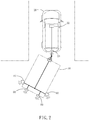
- FIG. 3 illustrates a radar system 40A installed in a trailer vehicle 10A in accordance with a second embodiment of the present invention.
- the trailer vehicle 10A comprises a master vehicle 20A and a slave vehicle 30A.
- the master vehicle 20A comprises a main connector 21A mounted at a rear side thereof.
- the slave vehicle 30A comprises a sub connector 31A mounted at a front side thereof to face toward the main connector 21A of the master vehicle 20A and pivotally connectable to the main connector 21A of the master vehicle 20A.
- the radar system 40A provides only two radars 60A that are respectively mounted at the two opposite lateral long sides of the slave vehicle 30A near its rear side.
- these two radars 60A are inclined at the same time or in different directions toward the rear side of the slave vehicle 30A. It is worth mentioning that in an alternate form of this second embodiment, the radar system 40A simply provides one single radar 60A that is mounted at one lateral long side of the slave vehicle 30A near its rear side.
- the radar system 40A further comprises an electrical socket 211A and a mating electrical plug 311A.
- the electrical socket 211A is mounted in the main connector 21A of the master vehicle 20A and electrically connected to the electrical wire 51A of the host unit 50A.
- the electrical plug 311A is mounted at the sub connector 31A of the slave vehicle 30A to face toward the electrical socket 211A in the main connector 21A of the master vehicle 20A and electrically connected to the of the electrical wires 61A of the radars 60A.
- the host unit 50A in the master vehicle 20A is electrically connected with the electrical wires 61A of the radars 60A via the electrical wire 51A, the electrical plug 311A and the electrical socket 211A.
Landscapes
- Engineering & Computer Science (AREA)
- Radar, Positioning & Navigation (AREA)
- Remote Sensing (AREA)
- Physics & Mathematics (AREA)
- Computer Networks & Wireless Communication (AREA)
- General Physics & Mathematics (AREA)
- Electromagnetism (AREA)
- Transportation (AREA)
- Mechanical Engineering (AREA)
- Radar Systems Or Details Thereof (AREA)
Abstract
A radar system(40)installed in a trailer vehicle(10)including a master vehicle(20)having a main connector(21)disposed at a rear side thereof and a slave vehicle(30)having a sub connector(31)disposed at a front side thereof and pivotally connectable to the main connector(21)is disclosed to include a host unit(50)mounted in the master vehicle(20)and a radar(60)mounted at the slave vehicle(30)and electrically connected to the host unit(50)after connection between the main connector(21)and the sub connector(31).Thus, this arrangement achieves the proposed efficacy and purpose of the present invention to facilitate electrical connection and disconnection between the host unit(50)and the radar(60),allowing the driver to learn the information of the warning signal generated by the radar(60).
Description
- The present invention relates to vehicle radar technology and more particularly, to a radar system for used in a trailer vehicle.
- With the recent booming camping habits, the demand for trailers for camping has also gradually increased. The original RVs, sedans or SUVs are provided with a trailer to constitute camping trailers for camping. However, due to the large volume of the body of the camping trailer, when the driver of the RV, the sedan or the SUV wants to make a turn or to reverse the vehicle during driving, the body of the trailer often blocks the driver's line of sight. In the long run, it is inconvenient for the driver.
- Therefore, it is desirable to provide a trailer vehicle radar system that effectively solves the aforesaid problems.
- The present invention has been accomplished under the circumstances in view. It is the main object of the present invention to provide a radar system practical for use in a trailer vehicle, which facilitates electrical connection and disconnection between the host unit and the radars and has a warning effect to help the driver in making judgment.
- To achieve this and other objects of the present invention, a radar system is installed in a trailer vehicle. The trailer vehicle comprises a master vehicle and a slave vehicle. The master vehicle comprises a main connector mounted at a rear side thereof. The slave vehicle comprises a sub connector mounted at a front side thereof to face toward the main connector of the master vehicle and pivotally connectable to the main connector of the master vehicle. The radar system comprises an electrical socket mounted at the master vehicle, an electrical plug mounted at the slave vehicle, a host unit and a radar.
- The host unit is mounted in the master vehicle, comprising an electrical wire electrically connected to the main connector of the master vehicle or the electrical socket.
- The radar is mounted at the slave vehicle, comprising an electrical wire that is electrically connected to the sub connector of the slave vehicle or the electrical plug for conduction with the electrical wire of the host unit through the main connector of the master vehicle or the electrical socket.
- Preferably, the radar protrudes over the rear side of the slave vehicle or is mounted at the junction between the rear side of the slave vehicle and one lateral long side of the slave vehicle to incline toward the rear side of the slave vehicle.
- Other advantages and features of the present invention will be fully understood by reference to the following specification in conjunction with the accompanying drawings, in which like reference signs denote like components of structure.
-
-
FIG. 1 is a schematic top view of a trailer vehicle radar system in accordance with a first embodiment of the present invention. -
FIG. 2 is a schematic top view illustrating an operation status of the trailer vehicle radar system in accordance with the first embodiment of the present invention. -
FIG. 3 is a schematic top view of a trailer vehicle radar system in accordance with a second embodiment of the present invention. - Referring to
FIGS. 1 and2 , a trailer vehicle radar system in accordance with a first embodiment of the present invention is shown. As illustrated, theradar system 40 is installed in atrailer vehicle 10. Thetrailer vehicle 10 comprises amaster vehicle 20 and aslave vehicle 30. Theradar system 40 comprises ahost unit 50 and fourradars 60. - The
master vehicle 20 comprises amain connector 21 and a reversingradar 23 respectively mounted at a rear side thereof. It is worth mentioning that themaster vehicle 20 can be a RV (Recreation Vehicle), sedan or SUV (Sport Utility Vehicle). Themain connector 21 can be a main component of a latching device, magnetic fastener or hook fastener consisting of a metal, semiconductor or superconductor having a conductive function. The reversingradar 23 detects the direction of travel and will alarm if there is an object approaching the rear of themaster vehicle 20. - The
slave vehicle 30 comprises asub connector 31 mounted at a front side thereof to face toward themain connector 21 of themaster vehicle 20 and is electrically and pivotally connectable to themain connector 21 of themaster vehicle 20. It is worth mentioning that theslave vehicle 30 can be a trailer for camping trailer, truck trailer or large joint vehicle. Further, thesub connector 31 of theslave vehicle 30 is a subcomponent of the latching device, magnetic fastener or hook fastener consisting of a metal, semiconductor or superconductor having a conductive function. - The
host unit 50 is mounted in themaster vehicle 20 comprising anelectrical wire 51 electrically connected with themain connector 21 of themaster vehicle 20. - The
radars 60 are respectively protrudingly mounted at a rear side and two opposite lateral long sides of the body of theslave vehicle 30. The two ofradars 60 that are respectively protrudingly mounted at the two opposite lateral long sides of the body of theslave vehicle 30 form an inclination angle with the respective lateral long side of the body of theslave vehicle 30. Preferably, the other two ofradars 60 at the two opposite lateral long sides of the body of theslave vehicle 30 both or individually incline toward the rear side of the body of theslave vehicle 30. Eachradar 60 comprises anelectrical wire 61 electrically connected to thesub connector 31 of theslave vehicle 30 so that themain connector 21 of themaster vehicle 20 can be electrically coupled to theelectrical wire 51 of thehost unit 50. - According to the
radar system 40 disclosed in the first preferred embodiment of the present invention, which is suitable for installation in thetrailer vehicle 10, the desired effect is: - 1. It has means that facilitates electrical connection and disconnection. Referring to
FIG. 1 again, when wishing to connect themaster vehicle 20 of thetrailer vehicle 10 and theslave vehicle 30 in series, pivotally connect thesub connector 31 of theslave vehicle 30 to themain connector 21 of themaster vehicle 20, at this time, theelectrical wire 51 of thehost unit 50 of themaster vehicle 20 is electrically connected to thesub connector 31 of themain connector 21 to achieve electrical connection with theelectrical wires 61 of theradars 60 at theslave vehicle 30. Further, when wishing to disconnect theslave vehicle 30 from themaster vehicle 20, disconnect thesub connector 31 of theslave vehicle 30 from themain connector 21 of themaster vehicle 20. In other words, it achieves the proposed efficacy and purpose of the present invention to facilitate electrical connection and disconnection between thehost unit 50 and theradars 60. - 2. It provides individual warnings to facilitate driver's judgment. Referring to
FIG. 2 again, as described above, when the driver connects thehost unit 50 with theradars 60 at theslave vehicle 30, thehost unit 50 provides a radar activation signal through theelectrical wires radars 60 at theslave vehicle 30 to activate theradars 60; when the driver drives, turns or reverses themaster vehicle 20, the driver can learn the information of warning signals generated by theradars 60 at theslave vehicle 30 through the alert unit (such as buzzer or warning light) of thehost unit 50. Thus, the accident caused by driver due to driving dead angles will be greatly reduced. -
FIG. 3 illustrates aradar system 40A installed in atrailer vehicle 10A in accordance with a second embodiment of the present invention. This second embodiment is substantially similar to the aforesaid first embodiment. Similarly, thetrailer vehicle 10A comprises amaster vehicle 20A and aslave vehicle 30A. Themaster vehicle 20A comprises amain connector 21A mounted at a rear side thereof. Theslave vehicle 30A comprises asub connector 31A mounted at a front side thereof to face toward themain connector 21A of themaster vehicle 20A and pivotally connectable to themain connector 21A of themaster vehicle 20A. The exceptions are outlined hereinafter:
Theradar system 40A provides only tworadars 60A that are respectively mounted at the two opposite lateral long sides of theslave vehicle 30A near its rear side. Preferably, these tworadars 60A are inclined at the same time or in different directions toward the rear side of theslave vehicle 30A. It is worth mentioning that in an alternate form of this second embodiment, theradar system 40A simply provides onesingle radar 60A that is mounted at one lateral long side of theslave vehicle 30A near its rear side. - The
radar system 40A further comprises anelectrical socket 211A and a matingelectrical plug 311A. Theelectrical socket 211A is mounted in themain connector 21A of themaster vehicle 20A and electrically connected to theelectrical wire 51A of thehost unit 50A. Theelectrical plug 311A is mounted at thesub connector 31A of theslave vehicle 30A to face toward theelectrical socket 211A in themain connector 21A of themaster vehicle 20A and electrically connected to the of theelectrical wires 61A of theradars 60A. - When wishing to connect the
master vehicle 20A of thetrailer vehicle 10A and theslave vehicle 30A in series, pivotally connect thesub connector 31A of theslave vehicle 30A to themain connector 21A of themaster vehicle 20A, and then connect theelectrical plug 311A at thesub connector 31A of themain connector 21A toelectrical socket 211A in themain connector 21A of themaster vehicle 20A. At this time, thehost unit 50A in themaster vehicle 20A is electrically connected with theelectrical wires 61A of theradars 60A via theelectrical wire 51A, theelectrical plug 311A and theelectrical socket 211A.
Claims (8)
- A radar system (40) installed in a trailer vehicle (10) comprising a master vehicle (20) and a slave vehicle (30), said master vehicle (20) comprising a main connector (21) mounted at a rear side thereof, said slave vehicle (30) comprising a sub connector (31) mounted at a front side thereof to face toward said main connector (21) of said master vehicle (20) and pivotally connector to said main connector (21) of said master vehicle (20), the radar system (40) comprising:a host unit (50) mounted in said master vehicle (20), said host unit (50) comprising an electrical wire (51) electrically connected to said main connector (21) of said master vehicle (20); andat least one radar (60) mounted on said slave vehicle (30), each said radar (60) comprising an electrical wire (61) electrically connected to said main connector (21) of said master vehicle (20);wherein said host unit (50) provides a radar activation signal through the electrical wire (51),(61) thereof to each said radar (60) to activate each said radar (60) when said at least one radar (60) is electrically connected to said host unit (50).
- A radar system (40A) installed in a trailer vehicle (10A) comprising a master vehicle (20A) and a slave vehicle (30A), said master vehicle (20A) comprising a main connector (21A) mounted at a rear side thereof, said slave vehicle (30A) comprising a sub connector (31A) mounted at a front side thereof to face toward said main connector (21A) of said master vehicle (20A) and pivotally connector to said main connector (21A) of said master vehicle (20A), the radar system (40A) comprising:an electrical socket (211A) mounted in said main connector (21A) of said master vehicle (20A);an electrical plug (311A) mounted at said sub connector (31A) of said slave vehicle (30A) and electrically connectable to said electrical socket (211A);a host unit (50A) mounted in said master vehicle (20A), said host unit (50A) comprising an electrical wire (51A) electrically connected to said electrical socket (211A); andat least one radar (60A) mounted at said slave vehicle (30A), each said radar (60A) comprising an electrical wire (61A) electrically connected to said electrical plug (311A) for conduction with the electrical wire (51A) of said host unit (50A) electrically;wherein when said host unit (50A) is switched to an alert mode, said host unit (50A) transmits a radar activation signal through the electrical wire (51A) of said host unit (50A), said electrical socket (211A), said electrical plug (311A) and the electrical wire (61A) of each said radar (60A) to each said radar (60A) to activate each said radar (60A).
- The radar system as claimed in claim 1 or 2, wherein each said radar (60),(60A) protrudes over the rear side of said slave vehicle (30),(30A).
- The radar system as claimed in claim 1 or 2, wherein each said radar (60),(60A) protrudes over the junction between one respective lateral long side of said slave vehicle (30),(30A) and the rear side of said slave vehicle (30),(30A).
- The radar system as claimed in claim 4, wherein said radar (60),(60A) is inclined toward the rear side of said slave vehicle (30),(30A), forming an inclination angle with each of two opposite lateral long sides of said slave vehicle (30),(30A).
- The radar system as claimed in claim 1 or 2, wherein the number of said at least one radar (60),(60A) is plural, and the multiple said radars (60),(60A) respectively protrude over the rear side of said slave vehicle (30),(30A).
- The radar system as claimed in claim 1 or 2, wherein the number of said at least one radar (60),(60A) is plural, and the multiple said radars (60),(60A) respectively protrude over the junctions between the rear side of said slave vehicle (30),(30A) and the two opposite lateral long sides of said slave vehicle (30),(30A).
- The radar system as claimed in claim 7, wherein the number of said at least one radar (60),(60A) is plural, and the multiple said radars (60),(60A) respectively incline toward the rear side of said slave vehicle (30),(30A), forming an inclination angle with each of the two opposite lateral long sides of said slave vehicle (30),(30A).
Applications Claiming Priority (1)
| Application Number | Priority Date | Filing Date | Title |
|---|---|---|---|
| TW107205987U TWM566679U (en) | 2018-05-08 | 2018-05-08 | Radar system for trailer |
Publications (1)
| Publication Number | Publication Date |
|---|---|
| EP3567402A1 true EP3567402A1 (en) | 2019-11-13 |
Family
ID=62599509
Family Applications (1)
| Application Number | Title | Priority Date | Filing Date |
|---|---|---|---|
| EP18177060.3A Withdrawn EP3567402A1 (en) | 2018-05-08 | 2018-06-11 | Radar system for trailer vehicle |
Country Status (3)
| Country | Link |
|---|---|
| US (1) | US20190346560A1 (en) |
| EP (1) | EP3567402A1 (en) |
| TW (1) | TWM566679U (en) |
Cited By (1)
| Publication number | Priority date | Publication date | Assignee | Title |
|---|---|---|---|---|
| EP4105676A1 (en) * | 2021-06-16 | 2022-12-21 | Robert Bosch GmbH | Driver assistance system and method for operating a driver assistance system |
Families Citing this family (1)
| Publication number | Priority date | Publication date | Assignee | Title |
|---|---|---|---|---|
| CN114604108B (en) * | 2022-01-14 | 2023-10-20 | 北京市农林科学院智能装备技术研究中心 | A master-slave vehicle cooperative operation control device and method |
Citations (3)
| Publication number | Priority date | Publication date | Assignee | Title |
|---|---|---|---|---|
| DE10035124A1 (en) * | 2000-07-19 | 2002-01-31 | Volkswagen Ag | Electronic distance warning system |
| US6380883B1 (en) * | 1998-02-23 | 2002-04-30 | Amerigon | High performance vehicle radar system |
| US20170334355A1 (en) * | 2014-10-21 | 2017-11-23 | Spirited Eagle Enterprises, LLC | System and method for enhancing driver situation awareness and environment perception around a transporation vehicle |
Family Cites Families (15)
| Publication number | Priority date | Publication date | Assignee | Title |
|---|---|---|---|---|
| US5421600A (en) * | 1992-10-02 | 1995-06-06 | Jones; Emery | Trailer coupler safety system |
| US6069581A (en) * | 1998-02-20 | 2000-05-30 | Amerigon | High performance vehicle radar system |
| US6400308B1 (en) * | 1998-02-20 | 2002-06-04 | Amerigon Inc. | High performance vehicle radar system |
| US6894608B1 (en) * | 1999-07-22 | 2005-05-17 | Altra Technologies Incorporated | System and method for warning of potential collisions |
| GB0005312D0 (en) * | 2000-02-28 | 2000-04-26 | Britax Wingard Ltd | Mounting for proximity radar |
| US6933837B2 (en) * | 2002-01-25 | 2005-08-23 | Altra Technologies Incorporated | Trailer based collision warning system and method |
| US9164955B2 (en) * | 2013-02-04 | 2015-10-20 | Ford Global Technologies | Trailer active back-up assist with object avoidance |
| US9444207B1 (en) * | 2015-06-04 | 2016-09-13 | Steve Smith | Ergonomic vehicle trailer electrical connector and circuit indicator |
| US10173623B1 (en) * | 2016-01-20 | 2019-01-08 | Delta Mobile Systems, Inc | Sensor bracket apparatus |
| US9738125B1 (en) * | 2016-05-17 | 2017-08-22 | Horizon Global Americas Inc. | Communication device, system, and method for active control of external vehicle components |
| US10286916B2 (en) * | 2016-06-20 | 2019-05-14 | Aptiv Technologies Limited | Trailer estimation and blind spot information system performance improvement |
| DE102016116859A1 (en) * | 2016-09-08 | 2018-03-08 | Knorr-Bremse Systeme für Nutzfahrzeuge GmbH | Sensor arrangement for an autonomously operated commercial vehicle and a method for round imaging |
| DE102017118588A1 (en) * | 2017-08-15 | 2019-02-21 | Valeo Schalter Und Sensoren Gmbh | Method for monitoring a surrounding area of a team, monitoring device, driver assistance system and team |
| GB2568748B (en) * | 2017-11-28 | 2020-04-01 | Jaguar Land Rover Ltd | Projection apparatus |
| US11364885B2 (en) * | 2018-01-18 | 2022-06-21 | Vieletech Inc. | Smart trailer controller |
-
2018
- 2018-05-08 TW TW107205987U patent/TWM566679U/en not_active IP Right Cessation
- 2018-06-11 EP EP18177060.3A patent/EP3567402A1/en not_active Withdrawn
- 2018-06-18 US US16/010,810 patent/US20190346560A1/en not_active Abandoned
Patent Citations (3)
| Publication number | Priority date | Publication date | Assignee | Title |
|---|---|---|---|---|
| US6380883B1 (en) * | 1998-02-23 | 2002-04-30 | Amerigon | High performance vehicle radar system |
| DE10035124A1 (en) * | 2000-07-19 | 2002-01-31 | Volkswagen Ag | Electronic distance warning system |
| US20170334355A1 (en) * | 2014-10-21 | 2017-11-23 | Spirited Eagle Enterprises, LLC | System and method for enhancing driver situation awareness and environment perception around a transporation vehicle |
Cited By (1)
| Publication number | Priority date | Publication date | Assignee | Title |
|---|---|---|---|---|
| EP4105676A1 (en) * | 2021-06-16 | 2022-12-21 | Robert Bosch GmbH | Driver assistance system and method for operating a driver assistance system |
Also Published As
| Publication number | Publication date |
|---|---|
| US20190346560A1 (en) | 2019-11-14 |
| TWM566679U (en) | 2018-09-11 |
Similar Documents
| Publication | Publication Date | Title |
|---|---|---|
| US12184013B2 (en) | Rear camera system for a vehicle with a trailer | |
| US4040006A (en) | Jacknife warning system | |
| US5666103A (en) | Wireless safety indicator control system for towed vehicles | |
| AU2022387074A1 (en) | Force transducer for a multifunction trailer controller | |
| CN102205823A (en) | Distance sensor for vehicle with electrical connector | |
| EP3567402A1 (en) | Radar system for trailer vehicle | |
| US11745554B2 (en) | Taillight enhancement harness for a towed vehicle | |
| CN202098347U (en) | Automobile camera shooting switching controller and automobile camera shooting control system | |
| US20150061853A1 (en) | Repeater module for tire pressure monitoring system | |
| CN112109716A (en) | Perception system of self-driving tractor and self-driving tractor | |
| US11772560B2 (en) | Trailer back-up system | |
| US4142172A (en) | Emergency power pack for vehicle trailer lights | |
| CN102941823B (en) | A kind of power engineering vehicle many visuals field finder being convenient to switch | |
| CN102941826B (en) | A kind of method and device guaranteeing power engineering vehicle driving safety | |
| JP2023502947A (en) | A method for configuring a trailer detection system | |
| US12054159B2 (en) | Computer program, communication circuit for a trailer, communication circuit for a vehicle, vehicle, trailer, and methods for communication between a vehicle and a trailer | |
| CN211032367U (en) | A Field of View Supplementary System for Vehicle Blind Spot Detection | |
| US20160318361A1 (en) | Trailer hitch ground connector | |
| US12210096B2 (en) | Ultrasonic radar system | |
| WO2023086357A2 (en) | Force transducer for a multifunction trailer controller | |
| CN210191332U (en) | Automobile radar and video combined early warning system | |
| CN111873909A (en) | Automobile driving assists image monitoring circuit | |
| US12479432B1 (en) | Pre-departure trailer based attachment detection system | |
| WO2017108508A1 (en) | Method for capturing an environmental region of a vehicle/trailer combination with a motor vehicle and a trailer as well as camera system | |
| CN201119260Y (en) | GPS products with parking system |
Legal Events
| Date | Code | Title | Description |
|---|---|---|---|
| PUAI | Public reference made under article 153(3) epc to a published international application that has entered the european phase |
Free format text: ORIGINAL CODE: 0009012 |
|
| STAA | Information on the status of an ep patent application or granted ep patent |
Free format text: STATUS: THE APPLICATION HAS BEEN PUBLISHED |
|
| AK | Designated contracting states |
Kind code of ref document: A1 Designated state(s): AL AT BE BG CH CY CZ DE DK EE ES FI FR GB GR HR HU IE IS IT LI LT LU LV MC MK MT NL NO PL PT RO RS SE SI SK SM TR |
|
| AX | Request for extension of the european patent |
Extension state: BA ME |
|
| STAA | Information on the status of an ep patent application or granted ep patent |
Free format text: STATUS: THE APPLICATION IS DEEMED TO BE WITHDRAWN |
|
| 18D | Application deemed to be withdrawn |
Effective date: 20200603 |