EP3567258A1 - Blade, impeller, and blower - Google Patents
Blade, impeller, and blower Download PDFInfo
- Publication number
- EP3567258A1 EP3567258A1 EP17890274.8A EP17890274A EP3567258A1 EP 3567258 A1 EP3567258 A1 EP 3567258A1 EP 17890274 A EP17890274 A EP 17890274A EP 3567258 A1 EP3567258 A1 EP 3567258A1
- Authority
- EP
- European Patent Office
- Prior art keywords
- blade
- ridge structure
- radial
- edge
- concave arc
- Prior art date
- Legal status (The legal status is an assumption and is not a legal conclusion. Google has not performed a legal analysis and makes no representation as to the accuracy of the status listed.)
- Pending
Links
- 238000005452 bending Methods 0.000 claims description 6
- 238000009434 installation Methods 0.000 claims description 6
- 230000007704 transition Effects 0.000 claims description 3
- 230000007423 decrease Effects 0.000 claims description 2
- 235000001968 nicotinic acid Nutrition 0.000 abstract description 3
- 230000003068 static effect Effects 0.000 description 4
- 240000003380 Passiflora rubra Species 0.000 description 3
- 238000010586 diagram Methods 0.000 description 3
- 238000000034 method Methods 0.000 description 3
- 230000000694 effects Effects 0.000 description 2
- 230000013011 mating Effects 0.000 description 2
- 230000004075 alteration Effects 0.000 description 1
- 230000005484 gravity Effects 0.000 description 1
- 238000012986 modification Methods 0.000 description 1
- 230000004048 modification Effects 0.000 description 1
- 238000005457 optimization Methods 0.000 description 1
- 230000002093 peripheral effect Effects 0.000 description 1
- 230000008569 process Effects 0.000 description 1
- 238000000926 separation method Methods 0.000 description 1
- 238000004088 simulation Methods 0.000 description 1
Images




Classifications
-
- F—MECHANICAL ENGINEERING; LIGHTING; HEATING; WEAPONS; BLASTING
- F04—POSITIVE - DISPLACEMENT MACHINES FOR LIQUIDS; PUMPS FOR LIQUIDS OR ELASTIC FLUIDS
- F04D—NON-POSITIVE-DISPLACEMENT PUMPS
- F04D29/00—Details, component parts, or accessories
- F04D29/26—Rotors specially for elastic fluids
-
- F—MECHANICAL ENGINEERING; LIGHTING; HEATING; WEAPONS; BLASTING
- F04—POSITIVE - DISPLACEMENT MACHINES FOR LIQUIDS; PUMPS FOR LIQUIDS OR ELASTIC FLUIDS
- F04D—NON-POSITIVE-DISPLACEMENT PUMPS
- F04D29/00—Details, component parts, or accessories
- F04D29/26—Rotors specially for elastic fluids
- F04D29/32—Rotors specially for elastic fluids for axial flow pumps
- F04D29/38—Blades
- F04D29/384—Blades characterised by form
-
- F—MECHANICAL ENGINEERING; LIGHTING; HEATING; WEAPONS; BLASTING
- F04—POSITIVE - DISPLACEMENT MACHINES FOR LIQUIDS; PUMPS FOR LIQUIDS OR ELASTIC FLUIDS
- F04D—NON-POSITIVE-DISPLACEMENT PUMPS
- F04D29/00—Details, component parts, or accessories
- F04D29/08—Sealings
- F04D29/16—Sealings between pressure and suction sides
- F04D29/161—Sealings between pressure and suction sides especially adapted for elastic fluid pumps
- F04D29/164—Sealings between pressure and suction sides especially adapted for elastic fluid pumps of an axial flow wheel
-
- F—MECHANICAL ENGINEERING; LIGHTING; HEATING; WEAPONS; BLASTING
- F04—POSITIVE - DISPLACEMENT MACHINES FOR LIQUIDS; PUMPS FOR LIQUIDS OR ELASTIC FLUIDS
- F04D—NON-POSITIVE-DISPLACEMENT PUMPS
- F04D29/00—Details, component parts, or accessories
- F04D29/26—Rotors specially for elastic fluids
- F04D29/32—Rotors specially for elastic fluids for axial flow pumps
- F04D29/325—Rotors specially for elastic fluids for axial flow pumps for axial flow fans
- F04D29/326—Rotors specially for elastic fluids for axial flow pumps for axial flow fans comprising a rotating shroud
-
- F—MECHANICAL ENGINEERING; LIGHTING; HEATING; WEAPONS; BLASTING
- F04—POSITIVE - DISPLACEMENT MACHINES FOR LIQUIDS; PUMPS FOR LIQUIDS OR ELASTIC FLUIDS
- F04D—NON-POSITIVE-DISPLACEMENT PUMPS
- F04D29/00—Details, component parts, or accessories
- F04D29/66—Combating cavitation, whirls, noise, vibration or the like; Balancing
- F04D29/661—Combating cavitation, whirls, noise, vibration or the like; Balancing especially adapted for elastic fluid pumps
- F04D29/666—Combating cavitation, whirls, noise, vibration or the like; Balancing especially adapted for elastic fluid pumps by means of rotor construction or layout, e.g. unequal distribution of blades or vanes
-
- F—MECHANICAL ENGINEERING; LIGHTING; HEATING; WEAPONS; BLASTING
- F04—POSITIVE - DISPLACEMENT MACHINES FOR LIQUIDS; PUMPS FOR LIQUIDS OR ELASTIC FLUIDS
- F04D—NON-POSITIVE-DISPLACEMENT PUMPS
- F04D29/00—Details, component parts, or accessories
- F04D29/66—Combating cavitation, whirls, noise, vibration or the like; Balancing
- F04D29/661—Combating cavitation, whirls, noise, vibration or the like; Balancing especially adapted for elastic fluid pumps
- F04D29/667—Combating cavitation, whirls, noise, vibration or the like; Balancing especially adapted for elastic fluid pumps by influencing the flow pattern, e.g. suppression of turbulence
-
- F—MECHANICAL ENGINEERING; LIGHTING; HEATING; WEAPONS; BLASTING
- F04—POSITIVE - DISPLACEMENT MACHINES FOR LIQUIDS; PUMPS FOR LIQUIDS OR ELASTIC FLUIDS
- F04D—NON-POSITIVE-DISPLACEMENT PUMPS
- F04D29/00—Details, component parts, or accessories
- F04D29/66—Combating cavitation, whirls, noise, vibration or the like; Balancing
- F04D29/68—Combating cavitation, whirls, noise, vibration or the like; Balancing by influencing boundary layers
- F04D29/681—Combating cavitation, whirls, noise, vibration or the like; Balancing by influencing boundary layers especially adapted for elastic fluid pumps
-
- F—MECHANICAL ENGINEERING; LIGHTING; HEATING; WEAPONS; BLASTING
- F05—INDEXING SCHEMES RELATING TO ENGINES OR PUMPS IN VARIOUS SUBCLASSES OF CLASSES F01-F04
- F05D—INDEXING SCHEME FOR ASPECTS RELATING TO NON-POSITIVE-DISPLACEMENT MACHINES OR ENGINES, GAS-TURBINES OR JET-PROPULSION PLANTS
- F05D2240/00—Components
- F05D2240/20—Rotors
- F05D2240/30—Characteristics of rotor blades, i.e. of any element transforming dynamic fluid energy to or from rotational energy and being attached to a rotor
- F05D2240/304—Characteristics of rotor blades, i.e. of any element transforming dynamic fluid energy to or from rotational energy and being attached to a rotor related to the trailing edge of a rotor blade
-
- F—MECHANICAL ENGINEERING; LIGHTING; HEATING; WEAPONS; BLASTING
- F05—INDEXING SCHEMES RELATING TO ENGINES OR PUMPS IN VARIOUS SUBCLASSES OF CLASSES F01-F04
- F05D—INDEXING SCHEME FOR ASPECTS RELATING TO NON-POSITIVE-DISPLACEMENT MACHINES OR ENGINES, GAS-TURBINES OR JET-PROPULSION PLANTS
- F05D2240/00—Components
- F05D2240/20—Rotors
- F05D2240/30—Characteristics of rotor blades, i.e. of any element transforming dynamic fluid energy to or from rotational energy and being attached to a rotor
- F05D2240/305—Characteristics of rotor blades, i.e. of any element transforming dynamic fluid energy to or from rotational energy and being attached to a rotor related to the pressure side of a rotor blade
-
- F—MECHANICAL ENGINEERING; LIGHTING; HEATING; WEAPONS; BLASTING
- F05—INDEXING SCHEMES RELATING TO ENGINES OR PUMPS IN VARIOUS SUBCLASSES OF CLASSES F01-F04
- F05D—INDEXING SCHEME FOR ASPECTS RELATING TO NON-POSITIVE-DISPLACEMENT MACHINES OR ENGINES, GAS-TURBINES OR JET-PROPULSION PLANTS
- F05D2240/00—Components
- F05D2240/20—Rotors
- F05D2240/30—Characteristics of rotor blades, i.e. of any element transforming dynamic fluid energy to or from rotational energy and being attached to a rotor
- F05D2240/306—Characteristics of rotor blades, i.e. of any element transforming dynamic fluid energy to or from rotational energy and being attached to a rotor related to the suction side of a rotor blade
Definitions
- the present disclosure relates to the field of fans, and in particular to a blade, an impeller and a fan.
- some embodiments of the present disclosure is to provide a blade, an impeller and a fan, which can improve the fan performance and reduce the blade broadband noise.
- a blade is provided.
- a trailing edge of the blade may be provided with at least one concave arc segment. At least one end point of the at least one concave arc segment may be located between a radial outer edge of the blade and a radial inner edge of the blade.
- the blade may be provided with at least one ridge structure protruding from a pressure surface of the blade toward a suction surface of the blade.
- one end of each of the at least one ridge structure is located at an end point of the at least one concave arc segment, and the other end of each of the at least one ridge structure is located at a leading edge of the blade.
- two end points of each of the at least one concave arc segment may be correspondingly provided with two ridge structures.
- the blade may be provided with multiple ridge structures from the radial inner edge of the blade toward the radial outer edge at intervals, and a maximum height of the ridge structures may gradually decrease from the radial inner edge of the blade toward the radial outer edge.
- the trailing edge of the blade may be provided with a concave arc segment
- the at least one ridge structure protruding from the pressure surface of the blade toward the suction surface of the blade may include a first ridge structure close to the radial inner edge of the blade and a second ridge structure close to the radial outer edge of the blade, one end of the first ridge structure is located at an end point of the concave arc segment close to the radial inner edge of the blade, and the second ridge structure is located at an end point of the concave arc segment close to the radial outer edge of the blade.
- the first ridge structure may have a maximum height W1
- the second ridge structure may have a maximum height W2
- a distance between the radial inner edge of the blade and the radial outer edge may be L.
- each of the at least one ridge structure has a circular arc shape.
- the trailing edge of the blade may be provided with a concave arc segment
- the at least one ridge structure protruding from the pressure surface of the blade toward the suction surface of the blade may include a first ridge structure close to the radial inner edge of the blade and a second ridge structure close to the radial outer edge of the blade, one end of the first ridge structure is located at an end point of the concave arc segment close to the radial inner edge of the blade, the second ridge structure is located at an end point of the concave arc segment close to the radial outer edge of the blade, the first ridge structure may have an arc radius R2 in the circumferential direction, the second ridge structure may have an arc radius R3 in the circumferential direction, and the radial inner edge of the blade may have a radius R1.
- a center of each of the at least one ridge structure may coincide with a center of the radial inner edge of the blade.
- the trailing edge of the blade may be provided with a concave arc segment, and in five elementary stages where the blades are evenly distributed in sequence from the radial inner edge to the radial outer edge, a cascade solidity may be 0.84 to 0.86, 0.77 to 0.79, 0.54 to 0.56, 0.57 to 0.59, and 0.51 to 0.53, and/or, an installation angle may be 30.5 to 32.5, 24.5 to 26.5, 19.5 to 21.5, 15.5 to 17.5, and 13.0 to 15.0, and/or, a front bending angle may be 0°, 1° to 3°, 7° to 9°, 9° to 11°, and 17° to 19°.
- each of the at least one ridge structure has a sharp-angled structure, and the sharp-angled structure may be connected to the suction surface of the blade and the pressure surface of the blade separately by a smooth curved transition.
- the present disclosure provides an impeller.
- the impeller may include the above-described blade.
- the impeller may include multiple blades arranged in a circumferential direction, two adjacent blades of the blades may have an angle therebetween, and among angles, at least one angle of the angles may be different from the other angles of the angles in degree.
- the impeller may include seven blades, and in the circumferential direction, the angles between the adjacent blades may be 49.5° to 50.5°, 51.0° to 52.0°, 45.5° to 46.5°, 58.6° to 59.6°, 47.5° to 48.5°, 46.8° to 47.3°, and 57.5° to 58.5°.
- the impeller may include a hub and an outer ring, a radial inner edge of the blade may be connected to the hub, a radial outer edge of the blade may be connected to the outer ring, and a radial outer side of the outer ring may be provided with a groove.
- the radial outer side of the outer ring may be provided with multiple annular grooves, distributed at intervals along an axial direction of the outer ring.
- the present disclosure provides a fan.
- the fan may include the above-described impeller.
- the present disclosure provides a fan.
- the fan may include the above-described impeller and a flow guiding ring disposed on a radial outer side of an outer ring of the impeller.
- the blade provided by the present disclosure is provided with at least one concave arc segment at a trailing edge thereof on the basis of a bionics principle, and is further provided with a ridge structure, thus improving an airflow pattern at the trailing edge of the blade by means of changing a shape of the blade, and reducing noise accordingly.
- 1 blade; 11, leading edge; 12, trailing edge; 13, radial inner edge; 14, radial outer edge; 15, concave arc segment; 161, first ridge structure; 162, second ridge structure; 17, suction surface; 18, pressure surface; 2, hub; 3, outer ring; 31, groove; 3', outer ring, 4', flow guiding ring.
- the blade 1 in the present application is a sheet-like structure, and includes a leading edge 11, a trailing edge 12, a radial inner edge 13 and a radial outer edge 14.
- the trailing edge 12 of the blade 1 is provided with at least one concave arc segment 15, and at least one end point of the concave arc segment 15 is located between the radial outer edge 14 of the blade 1 and the radial inner edge 13 of the blade 1, that is, at least one end point of the concave arc segment 15 is located between a radial inner side of the radial outer edge 14 of the blade 1 and a radial outer side of the radial inner edge 13.
- two end points of the concave arc segment 15 are both located between the radial outer edge 14 and the radial inner edge 13 of the blade 1. Based on a bionics principle, by changing the shape of the blade 1, the blade is batwing, thus improving an airflow pattern at the trailing edge of the blade, and reducing noise accordingly.
- the number of the concave arc segments 15 is not limited and may be determined according to factors such as specific specifications of the blade 1.
- the specific arc of the concave arc segment 15 is not limited, and may be a circular arc shape or an arc having a constantly changing curvature.
- the curvature of the concave arc segment 15 gradually increases from the radial inner edge 13 of the blade 1 to the radial outer edge 14, and a better airflow pattern can be obtained.
- the blade 1 has a suction surface 17 and a pressure surface 18.
- the blade 1 is provided with at least one ridge structure protruding from the pressure surface 18 of the blade 1 toward the suction surface 17 of the blade 1. That is, the pressure surface 18 of the blade 1 is recessed such that both the pressure surface 18 and the suction surface 17 protrude toward the suction surface 17 along the pressure surface 18.
- the ridge structure cooperates with the concave arc segment 15 on the trailing edge 12 to further improve the flow pattern of an airflow and reduce the broadband noise of the blade 1.
- the shape of the ridge structure is not limited in particular.
- each of the at least one ridge structure has a sharp-angled structure, and the sharp-angled structure is preferably connected to the suction surface 17 of the blade 1 and the pressure surface 18 via a smooth curved transition.
- the sharp-angled structure is preferably connected to the suction surface 17 of the blade 1 and the pressure surface 18 via a smooth curved transition.
- the arrangement of the ridge structure on the blade is not limited.
- one end is located at the leading edge 11 of the blade 1
- the other end of each of the at least one ridge structure is located at the trailing edge 12 of the blade.
- one end of each of the at least one ridge structure is located at an end point of the at least one concave arc segment 15, and the other end of each of the at least one ridge structure is located at the leading edge 11 of the blade.
- the ridge structure and the concave arc segment 15 can form a structure that more closely resembles a batwing, thereby achieving a superior airflow pattern.
- the concave arc segment 15 is disposed in the middle of the radial direction of the blade 1 (the definition of a specific position can be obtained by defining the ridge structure later).
- the concave arc segment 15 has two end points, namely a first end point close to the radial inner edge 13 of the blade and a second end point close to the radial outer edge 14 of the blade.
- the blade 1 is provided with two ridge structures, namely a first ridge structure 161 close to the radial inner edge 13 of the blade and a second ridge structure 162 close to the radial outer edge 14 of the blade.
- One end of the first ridge structure 161 meets the first end point, and the other end of each of the at least one ridge structure meets the leading edge 11 of the blade.
- One end of the second ridge structure 162 meets the second end point, and the other end of each of the at least one ridge structure meets the leading edge 11 of the blade.
- the ridge structure preferably has a circular arc shape in the circumferential direction, and more preferably, in a plane perpendicular to the axial direction, the circles of the radial inner edge 13 of the blade 1, the radial outer edge 14, the first ridge structure 161 and the ridge structure 162 are concentric.
- a maximum height of the ridge structures is gradually reduced from the radial inner edge of the blade to the radially outer edge.
- the maximum height of the ridge structures is a vertical distance between a point of a center line of the blade 1 at the top end position of the sharp-angled structure of the ridge structure and a gravity connecting line AB from the radial inner edge 13 of the blade 1 to the radial outer edge 14.
- the maximum height of the first ridge structure 161 is W1
- the maximum height of the second ridge structure 162 is W2
- W2 is smaller than W1.
- a distance between the radial inner edge 13 of the blade 1 and the radial outer edge 14 is L, and the radial direction described herein is not a projection direction in a plane perpendicular to the axial direction. Since the blade 1 has a certain angle with respect to the axial direction after installation, the radial direction here is that a radial line is drawn at the center, the radial line can be intersected with the radial inner edge 13 and the radial outer edge 14, and the distance between the two intersections is the distance L.
- the first ridge structure 161 has an arc radius R2 in the circumferential direction
- the second ridge structure 162 has an arc radius R3 in the circumferential direction
- the radial inner edge 13 of the blade 1 has a radius R1.
- a cascade solidity is 0.84 to 0.86, 0.77 to 0.79, 0.54 to 0.56, 0.57 to 0.59, and 0.51 to 0.53
- an installation angle ( ⁇ 1, ⁇ 2, ⁇ 3, ⁇ 4, and ⁇ 5 from the radial inner edge to the radial outer edge) is 30.5 to 32.5, 24.5 to 26.5, 19.5 to 21.5, 15.5 to 17.5, and 13.0 to 15.0
- a front bending angle ( ⁇ 1, ⁇ 2, ⁇ 3, ⁇ 4, and ⁇ 5 from the radial inner edge to the radial outer edge) is 0°, 1° to 3°, 7° to 9°, 9° to 11°, and 17° to 19°.
- the elementary stage is a portion where the circumferential surface of the radius R intersects with the blade 1 in the axial direction, the circumferential surfaces of different radius R can intersect with the blade 1 to form different elementary stages, and the blade is composed of an infinite number of elementary stages.
- the installation angle is an angle between a blade chord and a direction of rotation.
- a front bending angle is an angle between connecting lines of the centers of different elementary stages and the center of rotation of the blade. By default, the front bending angle of the first elementary stage is 0°.
- the present application also provides an impeller, adopting the above blade.
- the impeller includes a hub 2. Radial inner edges 13 of multiple blades 1 are fixed to the peripheral surface of the hub 2 and distributed along a circumferential direction.
- the corresponding ridge structures on multiple blades 1 are respectively located on the same circle.
- the first ridge structures 161 of the multiple blades 1 are all located on the same circle, and the second ridge structures 162 of the multiple blades 1 are also located on the same circle.
- the blades of the existing impeller are generally arranged evenly in the circumferential direction, and the airflow flowing through the blades and the blades are periodically beaten, thereby generating a dipole noise source, that is, a blade passing noise.
- This type of noise is a narrow-band noise, the fundamental frequency noise value is the highest, the fundamental frequency increases with the increase of the speed and the number of blades, and the sound quality is extremely unpleasant and unacceptable.
- at least one of the angles between adjacent blades 1 is different from the other angles of the angles in degree, and the non-equal spacing can control the noise peak to some extent, especially the peak corresponding to the fundamental frequency.
- the term "angle" is defined as the angle between the radial outer end of the leading edge of the blade and the center line.
- the impeller includes seven blades. In the circumferential direction, the angles between the adjacent blades 1 are ⁇ 1, ⁇ 2, ⁇ 3, ⁇ 4, ⁇ 5, ⁇ 6, and ⁇ 7.
- ⁇ 1 ranges from 49.5° to 50.5°
- ⁇ 2 ranges from 51.0° to 52.0°
- ⁇ 3 ranges from 45.5° to 46.5°
- ⁇ 4 ranges from 58.6° to 59.6°
- ⁇ 5 ranges from 47.5° to 48.5°
- ⁇ 6 ranges from 46.8° to 47.3°
- ⁇ 7 ranges from 57.5° to 58.5°.
- the impeller further includes an outer ring 3.
- the radial inner edge 13 of the blade 1 is connected to the hub 2.
- the radial outer edge 14 is connected to the outer ring 3.
- a safety gap is provided between the outer ring 3' and the flow guiding ring 4'.
- an airflow inevitably flows through the gap, thereby causing the leakage, and resulting in reducing the fan efficiency.
- a groove 31 is provided on the radial outer side of the outer ring 3, so that the cross-sectional area of the outer ring 3 is repeatedly changed, thereby increasing the resistance of a flow path formed between the outer ring 3 and the flow guiding ring.
- the size of the groove 31 should not be too large, and should not be too small. If it is too large, the structural strength of the outer ring 3 is affected, and if it is too small, the effect of increasing the resistance is not achieved.
- the depth of the groove 31 is M1 ⁇ 0.5M2, M2 being the thickness of the outer ring.
- the range of the width of the groove 31 (i.e., the dimension in the axial direction) M3 is M1 ⁇ M3 ⁇ 2M1.
- the specific shape of the groove 31 is not limited, and is preferably annular, and multiple annular grooves 31 are spaced apart along the axial direction of the outer ring 3, thereby achieving a better effect of increasing the resistance.
- the cross-sectional shape of the groove 31 is not limited, and may be an arc as shown in Fig. 8 , or may be a polygon, for example, a rectangle, a semi-pentagon, a semi-hexagon, etc. as shown in Fig. 9 to Fig. 11 .
- the groove having a polygonal section can further increase the resistance to the airflow and reduce the leakage of the fan.
- the present application further provides a fan, which adopts the above-mentioned impeller, can effectively reduce the noise of the fan, and is more reliable in operation, less in leakage and high in efficiency.
- ⁇ 1, ⁇ 2, ⁇ 3, ⁇ 4, ⁇ 5, ⁇ 6, and ⁇ 7 are 50°, 51.5°, 46°, 59.1°, 48°, 47.3°, and 58°.
- the static pressure distribution of the pressure surface of the blade of the fan is shown in Fig. 12 . It can be seen from the figure that through a series of size optimization, the flow pattern of the airflow is further improved, and the broadband noise of the blade is reduced.
- the fan of the present application has high efficiency and low noise, the efficiency is 2.18% higher than that of the existing fan, the noise is reduced by 2.5 dB, and the fan has better performance than the existing fan.
- the fan provided by the present application can be widely applied to various devices that need to supply air, for example, to air conditioners, especially bus air conditioners.
Landscapes
- Engineering & Computer Science (AREA)
- Mechanical Engineering (AREA)
- General Engineering & Computer Science (AREA)
- Structures Of Non-Positive Displacement Pumps (AREA)
Abstract
Description
- The present disclosure relates to the field of fans, and in particular to a blade, an impeller and a fan.
- When the speed of a fan is high, especially when the speed is about 3200Rpm, the boundary layer separation is serious and the airflow turbulence is strong at a trailing edge of a blade when an airflow flows through the surface of the blade, which leads to high broadband noise of the blade, influence on the fan performance, and low use comfort.
- In view of this, some embodiments of the present disclosure is to provide a blade, an impeller and a fan, which can improve the fan performance and reduce the blade broadband noise.
- To achieve the above object, according to a first aspect, a blade is provided.
- A trailing edge of the blade may be provided with at least one concave arc segment. At least one end point of the at least one concave arc segment may be located between a radial outer edge of the blade and a radial inner edge of the blade. The blade may be provided with at least one ridge structure protruding from a pressure surface of the blade toward a suction surface of the blade.
- In an exemplary embodiment, one end of each of the at least one ridge structure is located at an end point of the at least one concave arc segment, and the other end of each of the at least one ridge structure is located at a leading edge of the blade.
- In an exemplary embodiment two end points of each of the at least one concave arc segment may be correspondingly provided with two ridge structures.
- In an exemplary embodiment, the blade may be provided with multiple ridge structures from the radial inner edge of the blade toward the radial outer edge at intervals, and a maximum height of the ridge structures may gradually decrease from the radial inner edge of the blade toward the radial outer edge.
- In an exemplary embodiment the trailing edge of the blade may be provided with a concave arc segment, the at least one ridge structure protruding from the pressure surface of the blade toward the suction surface of the blade may include a first ridge structure close to the radial inner edge of the blade and a second ridge structure close to the radial outer edge of the blade, one end of the first ridge structure is located at an end point of the concave arc segment close to the radial inner edge of the blade, and the second ridge structure is located at an end point of the concave arc segment close to the radial outer edge of the blade.
- In an exemplary embodiment, the first ridge structure may have a maximum height W1, the second ridge structure may have a maximum height W2, and in a radial direction, a distance between the radial inner edge of the blade and the radial outer edge may be
L. 
- In an exemplary embodiment, each of the at least one ridge structure has a circular arc shape.
- In an exemplary embodiment, the trailing edge of the blade may be provided with a concave arc segment, the at least one ridge structure protruding from the pressure surface of the blade toward the suction surface of the blade may include a first ridge structure close to the radial inner edge of the blade and a second ridge structure close to the radial outer edge of the blade, one end of the first ridge structure is located at an end point of the concave arc segment close to the radial inner edge of the blade, the second ridge structure is located at an end point of the concave arc segment close to the radial outer edge of the blade, the first ridge structure may have an arc radius R2 in the circumferential direction, the second ridge structure may have an arc radius R3 in the circumferential direction, and the radial inner edge of the blade may have a radius R1.


- In an exemplary embodiment, a center of each of the at least one ridge structure may coincide with a center of the radial inner edge of the blade.
- In an exemplary embodiment, the trailing edge of the blade may be provided with a concave arc segment, and in five elementary stages where the blades are evenly distributed in sequence from the radial inner edge to the radial outer edge,
a cascade solidity may be 0.84 to 0.86, 0.77 to 0.79, 0.54 to 0.56, 0.57 to 0.59, and 0.51 to 0.53, and/or,
an installation angle may be 30.5 to 32.5, 24.5 to 26.5, 19.5 to 21.5, 15.5 to 17.5, and 13.0 to 15.0, and/or,
a front bending angle may be 0°, 1° to 3°, 7° to 9°, 9° to 11°, and 17° to 19°. - In an exemplary embodiment, each of the at least one ridge structure has a sharp-angled structure, and the sharp-angled structure may be connected to the suction surface of the blade and the pressure surface of the blade separately by a smooth curved transition.
- According to a second aspect, the present disclosure provides an impeller.
- The impeller may include the above-described blade.
- In an exemplary embodiment, the impeller may include multiple blades arranged in a circumferential direction, two adjacent blades of the blades may have an angle therebetween, and among angles, at least one angle of the angles may be different from the other angles of the angles in degree.
- In an exemplary embodiment, the impeller may include seven blades, and in the circumferential direction, the angles between the adjacent blades may be 49.5° to 50.5°, 51.0° to 52.0°, 45.5° to 46.5°, 58.6° to 59.6°, 47.5° to 48.5°, 46.8° to 47.3°, and 57.5° to 58.5°.
- In an exemplary embodiment, the impeller may include a hub and an outer ring, a radial inner edge of the blade may be connected to the hub, a radial outer edge of the blade may be connected to the outer ring, and a radial outer side of the outer ring may be provided with a groove.
- In an exemplary embodiment, the radial outer side of the outer ring may be provided with multiple annular grooves, distributed at intervals along an axial direction of the outer ring.
- According to a third aspect, the present disclosure provides a fan.
- The fan may include the above-described impeller.
- According to a fourth aspect, the present disclosure provides a fan.
- The fan may include the above-described impeller and a flow guiding ring disposed on a radial outer side of an outer ring of the impeller.
- The blade provided by the present disclosure is provided with at least one concave arc segment at a trailing edge thereof on the basis of a bionics principle, and is further provided with a ridge structure, thus improving an airflow pattern at the trailing edge of the blade by means of changing a shape of the blade, and reducing noise accordingly.
- By means of the description for the embodiments of the present invention with reference to the accompanying drawings, the above and other objects, features and advantages of the present invention will become more apparent from:
-
Fig. 1 schematically shows a structure diagram of a blade according to a specific embodiment of the present invention; -
Fig. 2 schematically shows a structure diagram of five elementary stages of a blade according to a specific embodiment of the present invention; -
Fig. 3 shows a partial cross-sectional stereogram of an impeller according to a specific embodiment of the present invention; -
Fig. 4 shows a partial enlarged view of a part A inFig. 4 ; -
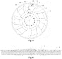
Fig. 5 shows a top view of an impeller according to a specific embodiment of the present invention; -
Fig. 6 shows a front view of an impeller according to a specific embodiment of the present invention; -
Fig. 7 schematically shows a structure diagram of a mating part of an outer ring and a flow guiding ring of an existing impeller; -
Fig. 8 shows a partial cross-sectional view of an impeller according to a specific embodiment of the present invention; -
Fig. 9 shows a partial cross-sectional view of another impeller according to a specific embodiment of the present invention; -
Fig. 10 shows a partial cross-sectional view of yet another impeller according to a specific embodiment of the present invention; -
Fig. 11 shows a partial cross-sectional view of a further impeller according to a specific embodiment of the present invention; and -
Fig. 12 shows a static pressure distribution view of a blade according to a specific embodiment of the present invention. - In the
figures, 1 , blade; 11, leading edge; 12, trailing edge; 13, radial inner edge; 14, radial outer edge; 15, concave arc segment; 161, first ridge structure; 162, second ridge structure; 17, suction surface; 18, pressure surface; 2, hub; 3, outer ring; 31, groove; 3', outer ring, 4', flow guiding ring. - The present disclosure is described below based on the embodiments, but the present disclosure is not limited to only these embodiments. In the following detailed description of the present disclosure, some specific details are described in detail. The present disclosure may be fully understood by those skilled in the art without the description of these details. In order to avoid obscuring the essence of the present disclosure, well-known methods, processes, procedures, and components are not described in detail.
- In addition, those of ordinary skill in the art should understand that the drawings are provided for the purpose of illustration, and the drawings are not necessarily to scale.
- Unless explicitly required by the context, similar words "including", "comprising", and the like in the whole specification and claims should be interpreted as inclusive meanings rather than exclusive or exhaustive meaning, that is, meanings of "including but not limited to".
- In the description of the present disclosure, it is to be understood that the terms "first", "second" and the like are used for descriptive purposes only and are not to be construed as indicating or implying relative importance. Further, in the description of the present disclosure, the meaning of "multiple" is two or more unless otherwise specified.
- The present disclosure provides a blade. As shown in
Fig. 1 to Fig. 4 , theblade 1 in the present application is a sheet-like structure, and includes a leadingedge 11, atrailing edge 12, a radialinner edge 13 and a radialouter edge 14. Thetrailing edge 12 of theblade 1 is provided with at least oneconcave arc segment 15, and at least one end point of theconcave arc segment 15 is located between the radialouter edge 14 of theblade 1 and the radialinner edge 13 of theblade 1, that is, at least one end point of theconcave arc segment 15 is located between a radial inner side of the radialouter edge 14 of theblade 1 and a radial outer side of the radialinner edge 13. Preferably, two end points of theconcave arc segment 15 are both located between the radialouter edge 14 and the radialinner edge 13 of theblade 1. Based on a bionics principle, by changing the shape of theblade 1, the blade is batwing, thus improving an airflow pattern at the trailing edge of the blade, and reducing noise accordingly. - The number of the
concave arc segments 15 is not limited and may be determined according to factors such as specific specifications of theblade 1. The specific arc of theconcave arc segment 15 is not limited, and may be a circular arc shape or an arc having a constantly changing curvature. Preferably, the curvature of theconcave arc segment 15 gradually increases from the radialinner edge 13 of theblade 1 to the radialouter edge 14, and a better airflow pattern can be obtained. - More preferably, the
blade 1 has asuction surface 17 and apressure surface 18. Theblade 1 is provided with at least one ridge structure protruding from thepressure surface 18 of theblade 1 toward thesuction surface 17 of theblade 1. That is, thepressure surface 18 of theblade 1 is recessed such that both thepressure surface 18 and thesuction surface 17 protrude toward thesuction surface 17 along thepressure surface 18. Thus, the ridge structure cooperates with theconcave arc segment 15 on the trailingedge 12 to further improve the flow pattern of an airflow and reduce the broadband noise of theblade 1. The shape of the ridge structure is not limited in particular. In a preferred embodiment, each of the at least one ridge structure has a sharp-angled structure, and the sharp-angled structure is preferably connected to thesuction surface 17 of theblade 1 and thepressure surface 18 via a smooth curved transition. Thus, the occurrence of an airflow dead angle can be avoided, thus improving the performance of a fan using it. - The arrangement of the ridge structure on the blade is not limited. Preferably, one end is located at the
leading edge 11 of theblade 1, and the other end of each of the at least one ridge structure is located at the trailingedge 12 of the blade. In order to better cooperate with theconcave arc segment 15 on the trailingedge 12 of the blade, more preferably, one end of each of the at least one ridge structure is located at an end point of the at least oneconcave arc segment 15, and the other end of each of the at least one ridge structure is located at theleading edge 11 of the blade. Thus, the ridge structure and theconcave arc segment 15 can form a structure that more closely resembles a batwing, thereby achieving a superior airflow pattern. - In the following, a specific mating structure of the
concave arc segment 15 and the ridge structure will be specifically described by taking aconcave arc segment 15 at the trailingedge 12 as an example. Theconcave arc segment 15 is disposed in the middle of the radial direction of the blade 1 (the definition of a specific position can be obtained by defining the ridge structure later). Theconcave arc segment 15 has two end points, namely a first end point close to the radialinner edge 13 of the blade and a second end point close to the radialouter edge 14 of the blade. Theblade 1 is provided with two ridge structures, namely afirst ridge structure 161 close to the radialinner edge 13 of the blade and asecond ridge structure 162 close to the radialouter edge 14 of the blade. One end of thefirst ridge structure 161 meets the first end point, and the other end of each of the at least one ridge structure meets the leadingedge 11 of the blade. One end of thesecond ridge structure 162 meets the second end point, and the other end of each of the at least one ridge structure meets the leadingedge 11 of the blade. Thus, a shape that more closely resembles a batwing can be formed, thereby improving the airflow at the trailingedge 12 of the blade, and reducing noise generated by the blade. - The ridge structure preferably has a circular arc shape in the circumferential direction, and more preferably, in a plane perpendicular to the axial direction, the circles of the radial
inner edge 13 of theblade 1, the radialouter edge 14, thefirst ridge structure 161 and theridge structure 162 are concentric. - In order to further optimize the flow pattern of the airflow, the structural parameters of various parts of the
blade 1 may be optimized. In a preferred embodiment, a maximum height of the ridge structures is gradually reduced from the radial inner edge of the blade to the radially outer edge. The maximum height of the ridge structures is a vertical distance between a point of a center line of theblade 1 at the top end position of the sharp-angled structure of the ridge structure and a gravity connecting line AB from the radialinner edge 13 of theblade 1 to the radialouter edge 14. In the embodiment shown inFig. 4 , the maximum height of thefirst ridge structure 161 is W1, the maximum height of thesecond ridge structure 162 is W2, and W2 is smaller than W1. - More preferably, as shown in
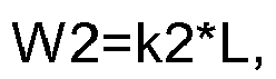
Fig. 4 , in a radial direction, a distance between the radialinner edge 13 of theblade 1 and the radialouter edge 14 is L, and the radial direction described herein is not a projection direction in a plane perpendicular to the axial direction. Since theblade 1 has a certain angle with respect to the axial direction after installation, the radial direction here is that a radial line is drawn at the center, the radial line can be intersected with the radialinner edge 13 and the radialouter edge 14, and the distance between the two intersections is the distance L. W1 and L preferably satisfy the relationship: W1=k1*L, a coefficient k1 ranging from 0.025 to 0.035. W2 and L preferably satisfy the relationship: W2=k2*L, a coefficient k2 ranging from 0.021 to 0.031. - In a preferred embodiment, as shown in
Fig. 5 , thefirst ridge structure 161 has an arc radius R2 in the circumferential direction, thesecond ridge structure 162 has an arc radius R3 in the circumferential direction, and the radialinner edge 13 of theblade 1 has a radius R1. R1 and R2 preferably satisfy the relationship: R2=k3*R1, a coefficient k3 ranging from 1.3 to 1.4. R1 and R3 preferably satisfy the relationship: R3=k4*R1, a coefficient k4 ranging from 1.95 to 2.05. - In a preferred embodiment, as shown in
Fig. 2 , in five elementary stages (S1, S2, S3, S4, and S5 from the radial inner edge to the radial outer edge) where theblades 1 are evenly distributed in sequence from the radialinner edge 13 to the radialouter edge 14, a cascade solidity is 0.84 to 0.86, 0.77 to 0.79, 0.54 to 0.56, 0.57 to 0.59, and 0.51 to 0.53, an installation angle (β1, β2, β3, β4, and β5 from the radial inner edge to the radial outer edge) is 30.5 to 32.5, 24.5 to 26.5, 19.5 to 21.5, 15.5 to 17.5, and 13.0 to 15.0, and a front bending angle (σ1, σ2, σ3, σ4, and σ5 from the radial inner edge to the radial outer edge) is 0°, 1° to 3°, 7° to 9°, 9° to 11°, and 17° to 19°. The elementary stage is a portion where the circumferential surface of the radius R intersects with theblade 1 in the axial direction, the circumferential surfaces of different radius R can intersect with theblade 1 to form different elementary stages, and the blade is composed of an infinite number of elementary stages. The installation angle is an angle between a blade chord and a direction of rotation. A front bending angle is an angle between connecting lines of the centers of different elementary stages and the center of rotation of the blade. By default, the front bending angle of the first elementary stage is 0°. - Further, the present application also provides an impeller, adopting the above blade. In a specific embodiment, as shown in
Fig. 3 to Fig. 6 , the impeller includes ahub 2. Radialinner edges 13 ofmultiple blades 1 are fixed to the peripheral surface of thehub 2 and distributed along a circumferential direction. Preferably, in a plane perpendicular to the axis of thehub 2, the corresponding ridge structures onmultiple blades 1 are respectively located on the same circle. For example, as shown inFig. 5 , thefirst ridge structures 161 of themultiple blades 1 are all located on the same circle, and thesecond ridge structures 162 of themultiple blades 1 are also located on the same circle. - The blades of the existing impeller are generally arranged evenly in the circumferential direction, and the airflow flowing through the blades and the blades are periodically beaten, thereby generating a dipole noise source, that is, a blade passing noise. This type of noise is a narrow-band noise, the fundamental frequency noise value is the highest, the fundamental frequency increases with the increase of the speed and the number of blades, and the sound quality is extremely unpleasant and unacceptable. In view of this problem, in the present application, at least one of the angles between
adjacent blades 1 is different from the other angles of the angles in degree, and the non-equal spacing can control the noise peak to some extent, especially the peak corresponding to the fundamental frequency. - In the present application, the term "angle" is defined as the angle between the radial outer end of the leading edge of the blade and the center line. In a specific embodiment, as shown in
Fig. 5 , the impeller includes seven blades. In the circumferential direction, the angles between theadjacent blades 1 are θ1, θ2, θ3, θ4, θ5, θ6, and θ7. θ1 ranges from 49.5° to 50.5°, θ2 ranges from 51.0° to 52.0°, θ3 ranges from 45.5° to 46.5°, θ4 ranges from 58.6° to 59.6°, θ5 ranges from 47.5° to 48.5°, θ6 ranges from 46.8° to 47.3°, and θ7 ranges from 57.5° to 58.5°. - In a further embodiment, the impeller further includes an
outer ring 3. The radialinner edge 13 of theblade 1 is connected to thehub 2. The radialouter edge 14 is connected to theouter ring 3. When the impeller is installed on the fan, the impeller is disposed in a flow guiding ring, that is, the flow guiding ring covers the outer circumference of the impeller such that the flow guiding ring is located on a radial outer side of theouter ring 3. - In the conventional art, as shown in
Fig. 7 , in order to prevent dynamic/static interference between an outer ring 3' and a flow guiding ring 4', a safety gap is provided between the outer ring 3' and the flow guiding ring 4'. During the operation of the fan, an airflow inevitably flows through the gap, thereby causing the leakage, and resulting in reducing the fan efficiency. In order to improve this phenomenon, in the present application, as shown inFig. 8 , agroove 31 is provided on the radial outer side of theouter ring 3, so that the cross-sectional area of theouter ring 3 is repeatedly changed, thereby increasing the resistance of a flow path formed between theouter ring 3 and the flow guiding ring. Thus, the safety gap can be ensured while reducing the leakage, thereby improving the fan efficiency. - The size of the
groove 31 should not be too large, and should not be too small. If it is too large, the structural strength of theouter ring 3 is affected, and if it is too small, the effect of increasing the resistance is not achieved. In a preferred embodiment, the depth of thegroove 31 is M1 ≤ 0.5M2, M2 being the thickness of the outer ring. The range of the width of the groove 31 (i.e., the dimension in the axial direction) M3 is M1 < M3 < 2M1. - The specific shape of the
groove 31 is not limited, and is preferably annular, and multipleannular grooves 31 are spaced apart along the axial direction of theouter ring 3, thereby achieving a better effect of increasing the resistance. The cross-sectional shape of thegroove 31 is not limited, and may be an arc as shown inFig. 8 , or may be a polygon, for example, a rectangle, a semi-pentagon, a semi-hexagon, etc. as shown inFig. 9 to Fig. 11 . The groove having a polygonal section can further increase the resistance to the airflow and reduce the leakage of the fan. - Further, the present application further provides a fan, which adopts the above-mentioned impeller, can effectively reduce the noise of the fan, and is more reliable in operation, less in leakage and high in efficiency.
- In a specific embodiment, the blade specific parameters of the fan are: R2=1.33R1, R3=1.99R1, W1 =0.299L, and W2=0.026L, the cascade solidity of S1, S2, S3, S4, and S5 are 0.85, 0.78, 0.55, 0.58, and 0.52, the installation angles are 31.5°, 25.5°, 20.5°, 16.5°, and 14.0°, and the front bending angles are 0°, 2°, 8°, 10°, and 18°. θ1, θ2, θ3, θ4, θ5, θ6, and θ7 are 50°, 51.5°, 46°, 59.1°, 48°, 47.3°, and 58°. The groove depth of the outer ring of the impeller is M1=0.5M2, M2 is the thickness of the outer ring, the groove width is M3=M1, and the cross-sectional shape of the groove is an arc as shown in
Fig. 8 . Through simulation experiments, the static pressure distribution of the pressure surface of the blade of the fan is shown inFig. 12 . It can be seen from the figure that through a series of size optimization, the flow pattern of the airflow is further improved, and the broadband noise of the blade is reduced. After specific experimental tests, the results of comparison with existing fans are shown in the following table:Speed n (Rpm) Static pressure (Pa) Air volume Q (m3/h) Fan efficiency η (%) Noise N (dB/A) Existing fan 3220 130 2100 39.19 78.3 Fan of the present application 3224 130 2150 41.37 75.8 - As can be seen from the above table, the fan of the present application has high efficiency and low noise, the efficiency is 2.18% higher than that of the existing fan, the noise is reduced by 2.5 dB, and the fan has better performance than the existing fan.
- The fan provided by the present application can be widely applied to various devices that need to supply air, for example, to air conditioners, especially bus air conditioners.
- It will be readily understood by those skilled in the art that the above various preferred solutions can be freely combined and superimposed without conflict.
- It will be appreciated that the above embodiments are to be considered as illustrative and not restrictive. Various obvious or equivalent modifications or alterations to the above details will be apparent to those skilled in the art without departing from the basic principle of the present disclosure, which are all included within the scope of the claims of the present disclosure.
Claims (18)
- A blade, wherein a trailing edge of the blade is provided with at least one concave arc segment, at least one end point of the at least one concave arc segment is located between a radial outer edge of the blade and a radial inner edge of the blade, and the blade is provided with at least one ridge structure protruding from a pressure surface of the blade toward a suction surface thereof.
- The blade as claimed in claim 1, wherein one end of each of the at least one ridge structure is located at an end point of the at least one concave arc segment, and the other end of each of the at least one ridge structure is located at a leading edge of the blade.
- The blade as claimed in claim 2, wherein two end points of each of the at least one concave arc segment are correspondingly provided with two ridge structures.
- The blade as claimed in claim 1, wherein the blade is provided with a plurality of ridge structures from the radial inner edge of the blade toward the radial outer edge at intervals, and a maximum height of the ridge structures gradually decreases from the radial inner edge of the blade toward the radial outer edge.
- The blade as claimed in claim 1, wherein the trailing edge of the blade is provided with a concave arc segment, the at least one ridge structure protruding from the pressure surface of the blade toward the suction surface of the blade comprises a first ridge structure close to the radial inner edge of the blade and a second ridge structure close to the radial outer edge of the blade, one end of the first ridge structure is located at an end point of the concave arc segment close to the radial inner edge of the blade, and the second ridge structure is located at an end point of the concave arc segment close to the radial outer edge of the blade.
- The blade as claimed in claim 5, wherein the first ridge structure has a maximum height W1, the second ridge structure has a maximum height W2, and in a radial direction, a distance between the radial inner edge of the blade and the radial outer edge is L,
where

- The blade as claimed in claim 1, wherein each of the at least one ridge structure has a circular arc shape in a circumferential direction.
- The blade as claimed in claim 7, wherein the trailing edge of the blade is provided with a concave arc segment, the at least one ridge structure protruding from the pressure surface of the blade toward the suction surface of the blade comprises a first ridge structure close to the radial inner edge of the blade and a second ridge structure close to the radial outer edge of the blade, one end of the first ridge structure is located at an end point of the concave arc segment close to the radial inner edge of the blade, the second ridge structure is located at an end point of the concave arc segment close to the radial outer edge of the blade, the first ridge structure has an arc radius R2 in the circumferential direction, the second ridge structure has an arc radius R3 in the circumferential direction, and the radial inner edge of the blade has a radius R1,
where

- The blade as claimed in claim 7, wherein a center of each of the at least one ridge structure coincides with a center of the radial inner edge of the blade.
- The blade as claimed in claim 5, wherein in five elementary stages where the blades are evenly distributed in sequence from the radial inner edge to the radial outer edge,
a cascade solidity is 0.84 to 0.86, 0.77 to 0.79, 0.54 to 0.56, 0.57 to 0.59, and 0.51 to 0.53, and/or,
an installation angle is 30.5 to 32.5, 24.5 to 26.5, 19.5 to 21.5, 15.5 to 17.5, and 13.0 to 15.0, and/or,
a front bending angle is 0°, 1° to 3°, 7° to 9°, 9° to 11°, and 17° to 19°. - The blade as claimed in claim 1, wherein each of the at least one ridge structure has a sharp-angled structure, and the sharp-angled structure is connected to the suction surface of the blade and the pressure surface of the blade separately by a smooth curved transition.
- An impeller, comprising a blade as claimed in any one of claims 1 to 11.
- The impeller as claimed in claim 12, comprising a plurality of blades arranged in a circumferential direction, wherein two adjacent blades of the blades have an angle therebetween, and among angles, at least one angle of the angles is different from the other angles of the angles in degree.
- The impeller as claimed in claim 13, comprising seven blades, wherein in the circumferential direction, the angles between the adjacent blades are 49.5° to 50.5°, 51.0° to 52.0°, 45.5° to 46.5°, 58.6° to 59.6°, 47.5° to 48.5°, 46.8° to 47.3°, and 57.5° to 58.5°.
- The impeller as claimed in any one of claims 12 to 14, comprising a hub and an outer ring, wherein a radial inner edge of the blade is connected to the hub, a radial outer edge of the blade is connected to the outer ring, and a radial outer side of the outer ring is provided with a groove.
- The impeller as claimed in claim 15, wherein the radial outer side of the outer ring is provided with a plurality of annular grooves, distributed at intervals along an axial direction of the outer ring.
- A fan, comprising an impeller as claimed in any one of claims 12 to 16.
- A fan, comprising an impeller as claimed in claim 15 or 16 and a flow guiding ring disposed on a radial outer side of an outer ring of the impeller.
Applications Claiming Priority (2)
| Application Number | Priority Date | Filing Date | Title |
|---|---|---|---|
| CN201710009207.9A CN106640748B (en) | 2017-01-06 | 2017-01-06 | Blade, impeller and fan |
| PCT/CN2017/103960 WO2018126745A1 (en) | 2017-01-06 | 2017-09-28 | Blade, impeller, and blower |
Publications (2)
| Publication Number | Publication Date |
|---|---|
| EP3567258A1 true EP3567258A1 (en) | 2019-11-13 |
| EP3567258A4 EP3567258A4 (en) | 2020-08-26 |
Family
ID=58843195
Family Applications (1)
| Application Number | Title | Priority Date | Filing Date |
|---|---|---|---|
| EP17890274.8A Pending EP3567258A4 (en) | 2017-01-06 | 2017-09-28 | SHOVEL, IMPELLER AND FAN |
Country Status (5)
| Country | Link |
|---|---|
| US (1) | US11078921B2 (en) |
| EP (1) | EP3567258A4 (en) |
| JP (1) | JP6771672B2 (en) |
| CN (1) | CN106640748B (en) |
| WO (1) | WO2018126745A1 (en) |
Families Citing this family (11)
| Publication number | Priority date | Publication date | Assignee | Title |
|---|---|---|---|---|
| CN106640748B (en) | 2017-01-06 | 2022-12-02 | 珠海格力电器股份有限公司 | Blade, impeller and fan |
| EP3421724A1 (en) * | 2017-06-26 | 2019-01-02 | Siemens Aktiengesellschaft | Compressor aerofoil |
| WO2019030868A1 (en) | 2017-08-09 | 2019-02-14 | 三菱電機株式会社 | Propeller fan, blower device, and refrigeration cycle device |
| KR102537524B1 (en) * | 2018-07-06 | 2023-05-30 | 엘지전자 주식회사 | Fan |
| CN109281866B (en) * | 2018-12-07 | 2023-09-15 | 泰州市罡阳喷灌机有限公司 | Bionic blades of water ring self-priming pump |
| CN109404305B (en) * | 2018-12-26 | 2023-11-21 | 浙江科贸智能机电股份有限公司 | Bionic blade volute-free centrifugal ventilator |
| CN111059076A (en) * | 2019-12-31 | 2020-04-24 | 佛山市云米电器科技有限公司 | Clustered fan blade structure with double fan blades, axial flow fan and air conditioner |
| CN111523220B (en) * | 2020-04-17 | 2023-03-21 | 中国空气动力研究与发展中心高速空气动力研究所 | Fan and compressor rotating-static interference broadband noise rapid prediction method considering flow influence |
| CN111828382B (en) * | 2020-07-10 | 2022-04-22 | 浙江科贸智能机电股份有限公司 | Impeller of bionic blade centrifugal ventilator |
| CN114046269B (en) * | 2022-01-11 | 2022-05-03 | 中国航发上海商用航空发动机制造有限责任公司 | Rotor blade of axial flow compressor and design method thereof |
| CN114688083B (en) * | 2022-04-28 | 2023-02-28 | 宁波方太厨具有限公司 | Blade, impeller applying same, fan system and range hood |
Family Cites Families (37)
| Publication number | Priority date | Publication date | Assignee | Title |
|---|---|---|---|---|
| US2774308A (en) * | 1952-04-22 | 1956-12-18 | Ulander Per Helge Natanael | Radial flow impellers |
| DE3408219A1 (en) * | 1984-03-07 | 1985-09-12 | Hugo Lahme GmbH, 5828 Ennepetal | Circulation pump for water-jet devices in bath tubs |
| US4789306A (en) * | 1985-11-15 | 1988-12-06 | Attwood Corporation | Marine propeller |
| US4830315A (en) * | 1986-04-30 | 1989-05-16 | United Technologies Corporation | Airfoil-shaped body |
| JP2000110785A (en) * | 1998-10-05 | 2000-04-18 | Calsonic Corp | Axial fan |
| JP2001082383A (en) | 1999-09-09 | 2001-03-27 | Sowa Denki Seisakusho:Kk | Impeller, centrifugal blower, and centrifugal pump |
| JP3391319B2 (en) * | 1999-12-01 | 2003-03-31 | ダイキン工業株式会社 | Centrifugal fan and air conditioner equipped with the centrifugal fan |
| JP4592908B2 (en) * | 2000-09-28 | 2010-12-08 | 株式会社ティラド | Fan seal structure |
| JP2002257088A (en) * | 2001-03-06 | 2002-09-11 | Toshiba Kyaria Kk | Axial fan |
| JP3978083B2 (en) | 2001-06-12 | 2007-09-19 | 漢拏空調株式会社 | Axial fan |
| US7008201B2 (en) * | 2001-10-19 | 2006-03-07 | Imperial Research Llc | Gapless screw rotor device |
| JP4432474B2 (en) * | 2003-11-27 | 2010-03-17 | ダイキン工業株式会社 | Centrifugal blower impeller and centrifugal blower provided with the impeller |
| JP4545009B2 (en) * | 2004-03-23 | 2010-09-15 | 三菱重工業株式会社 | Centrifugal compressor |
| CN100406747C (en) * | 2004-05-18 | 2008-07-30 | 建准电机工业股份有限公司 | Air inlet structure of axial flow fan |
| JP4576304B2 (en) * | 2005-08-03 | 2010-11-04 | 三菱重工業株式会社 | Propeller fan |
| JP4508974B2 (en) * | 2005-08-03 | 2010-07-21 | 三菱重工業株式会社 | Propeller fan |
| US7771171B2 (en) * | 2006-12-14 | 2010-08-10 | General Electric Company | Systems for preventing wear on turbine blade tip shrouds |
| US8087969B2 (en) * | 2007-09-15 | 2012-01-03 | Mattel, Inc. | Costume apparatus |
| SI22636A (en) | 2007-10-24 | 2009-04-30 | Hidria Rotomatika D.O.O. | Blade of axial fan with wavy pressure and suction surface |
| JP4400686B2 (en) * | 2008-01-07 | 2010-01-20 | ダイキン工業株式会社 | Propeller fan |
| JP5164932B2 (en) * | 2009-06-11 | 2013-03-21 | 三菱電機株式会社 | Turbofan and air conditioner |
| CN101725566A (en) | 2009-11-12 | 2010-06-09 | 广东顺威精密塑料股份有限公司 | Axial flow fan blade with middle bent blade |
| CN201739227U (en) * | 2009-11-12 | 2011-02-09 | 广东顺威精密塑料股份有限公司 | An axial flow fan blade with a bent middle part of the blade |
| US20130004316A1 (en) * | 2011-06-28 | 2013-01-03 | Honeywell International Inc. | Multi-piece centrifugal impellers and methods for the manufacture thereof |
| JP5792602B2 (en) * | 2011-11-25 | 2015-10-14 | 株式会社ティラド | Resin fan balance adjustment structure |
| WO2014061094A1 (en) * | 2012-10-16 | 2014-04-24 | 三菱電機株式会社 | Turbo fan and air conditioner |
| KR101353265B1 (en) * | 2012-10-19 | 2014-01-27 | 기아자동차주식회사 | Protection structure of motor for cooling-fan |
| CN102893951B (en) * | 2012-10-31 | 2013-11-06 | 无锡同春新能源科技有限公司 | Factory for feeding flour weevil and feeding bat with flour weevil to eliminate mosquito by regulating temperature and humidity by using power generated by wind-light complementary power generation system |
| CN203939767U (en) * | 2014-02-21 | 2014-11-12 | 广东顺德智电电子科技有限公司 | Cassette/locking-type carries net fan |
| JP6322098B2 (en) * | 2014-09-11 | 2018-05-09 | 日立ジョンソンコントロールズ空調株式会社 | Propeller fan and air conditioner equipped with the same |
| CN204186638U (en) * | 2014-10-17 | 2015-03-04 | 珠海格力电器股份有限公司 | Fan blade and fan provided with same |
| KR102344406B1 (en) * | 2015-04-08 | 2021-12-27 | 호르톤 인코포레이티드 | fan blade surface features |
| KR102403728B1 (en) * | 2015-10-07 | 2022-06-02 | 삼성전자주식회사 | Turbofan for air conditioning apparatus |
| CN105240317A (en) * | 2015-10-28 | 2016-01-13 | 佛山市富士宝电器科技股份有限公司 | Fan blade |
| US10465520B2 (en) * | 2016-07-22 | 2019-11-05 | General Electric Company | Blade with corrugated outer surface(s) |
| CN106640748B (en) * | 2017-01-06 | 2022-12-02 | 珠海格力电器股份有限公司 | Blade, impeller and fan |
| CN206530536U (en) * | 2017-01-06 | 2017-09-29 | 珠海格力电器股份有限公司 | Blade, impeller and fan |
-
2017
- 2017-01-06 CN CN201710009207.9A patent/CN106640748B/en active Active
- 2017-09-28 EP EP17890274.8A patent/EP3567258A4/en active Pending
- 2017-09-28 US US16/471,074 patent/US11078921B2/en active Active
- 2017-09-28 JP JP2019533011A patent/JP6771672B2/en active Active
- 2017-09-28 WO PCT/CN2017/103960 patent/WO2018126745A1/en not_active Ceased
Also Published As
| Publication number | Publication date |
|---|---|
| US20200018323A1 (en) | 2020-01-16 |
| CN106640748B (en) | 2022-12-02 |
| JP2020502421A (en) | 2020-01-23 |
| WO2018126745A1 (en) | 2018-07-12 |
| EP3567258A4 (en) | 2020-08-26 |
| CN106640748A (en) | 2017-05-10 |
| US11078921B2 (en) | 2021-08-03 |
| JP6771672B2 (en) | 2020-10-21 |
Similar Documents
| Publication | Publication Date | Title |
|---|---|---|
| US11078921B2 (en) | Blade, impeller and fan | |
| KR102317338B1 (en) | Blower and outdoor unit of air conditioner having the same | |
| AU2013321833B2 (en) | Propeller fan and air conditioner equipped with same | |
| US11098734B2 (en) | Propeller fan, air-conditioning apparatus and ventilator | |
| US10662973B2 (en) | Reversible flow fan | |
| CN111133201B (en) | Propeller Fans and Axial Blowers | |
| US20120114498A1 (en) | Fan structure | |
| US11391295B2 (en) | Propeller fan | |
| US10859095B2 (en) | Impeller and axial flow fan | |
| KR101981922B1 (en) | Pre-Tip Axial Fan Assembly | |
| KR101742965B1 (en) | Blower and outdoor unit of air conditioner having the same | |
| US11852158B1 (en) | Fan and impeller | |
| CN109538532A (en) | Axial flow fan blade, air interchanger and air conditioner | |
| KR20110083043A (en) | Crossflow fan and air conditioner having the same | |
| CN109915411A (en) | Axial flow fan and air conditioner having the same | |
| CN118815748A (en) | An axial flow impeller | |
| CN115898948B (en) | Blades and axial flow fans using them | |
| CN206206264U (en) | Impeller and the blower fan with it | |
| US10634162B2 (en) | Axial fan | |
| JP2015075035A (en) | Blower | |
| CN204878057U (en) | Fan blade and centrifugal ventilator | |
| CN104214137A (en) | Propeller type fan | |
| US20210199122A1 (en) | Propeller fan | |
| JP2006118496A (en) | Cross flow fan |
Legal Events
| Date | Code | Title | Description |
|---|---|---|---|
| STAA | Information on the status of an ep patent application or granted ep patent |
Free format text: STATUS: THE INTERNATIONAL PUBLICATION HAS BEEN MADE |
|
| PUAI | Public reference made under article 153(3) epc to a published international application that has entered the european phase |
Free format text: ORIGINAL CODE: 0009012 |
|
| STAA | Information on the status of an ep patent application or granted ep patent |
Free format text: STATUS: REQUEST FOR EXAMINATION WAS MADE |
|
| 17P | Request for examination filed |
Effective date: 20190620 |
|
| AK | Designated contracting states |
Kind code of ref document: A1 Designated state(s): AL AT BE BG CH CY CZ DE DK EE ES FI FR GB GR HR HU IE IS IT LI LT LU LV MC MK MT NL NO PL PT RO RS SE SI SK SM TR |
|
| REG | Reference to a national code |
Ref country code: DE Ref legal event code: R079 Free format text: PREVIOUS MAIN CLASS: F04D0029300000 Ipc: F04D0029380000 |
|
| A4 | Supplementary search report drawn up and despatched |
Effective date: 20200722 |
|
| RIC1 | Information provided on ipc code assigned before grant |
Ipc: F04D 29/68 20060101ALI20200718BHEP Ipc: F01D 5/14 20060101ALI20200718BHEP Ipc: F04D 29/66 20060101ALI20200718BHEP Ipc: F04D 29/38 20060101AFI20200718BHEP |
|
| STAA | Information on the status of an ep patent application or granted ep patent |
Free format text: STATUS: EXAMINATION IS IN PROGRESS |
|
| 17Q | First examination report despatched |
Effective date: 20220204 |
|
| P01 | Opt-out of the competence of the unified patent court (upc) registered |
Effective date: 20230530 |