EP3567140A1 - Layered carbon fiber - Google Patents
Layered carbon fiber Download PDFInfo
- Publication number
- EP3567140A1 EP3567140A1 EP19165301.3A EP19165301A EP3567140A1 EP 3567140 A1 EP3567140 A1 EP 3567140A1 EP 19165301 A EP19165301 A EP 19165301A EP 3567140 A1 EP3567140 A1 EP 3567140A1
- Authority
- EP
- European Patent Office
- Prior art keywords
- carbon
- nanotube yarn
- carbon nanotube
- polyacrylonitrile
- layered
- Prior art date
- Legal status (The legal status is an assumption and is not a legal conclusion. Google has not performed a legal analysis and makes no representation as to the accuracy of the status listed.)
- Pending
Links
Images



Classifications
-
- D—TEXTILES; PAPER
- D01—NATURAL OR MAN-MADE THREADS OR FIBRES; SPINNING
- D01F—CHEMICAL FEATURES IN THE MANUFACTURE OF ARTIFICIAL FILAMENTS, THREADS, FIBRES, BRISTLES OR RIBBONS; APPARATUS SPECIALLY ADAPTED FOR THE MANUFACTURE OF CARBON FILAMENTS
- D01F8/00—Conjugated, i.e. bi- or multicomponent, artificial filaments or the like; Manufacture thereof
- D01F8/18—Conjugated, i.e. bi- or multicomponent, artificial filaments or the like; Manufacture thereof from other substances
-
- D—TEXTILES; PAPER
- D01—NATURAL OR MAN-MADE THREADS OR FIBRES; SPINNING
- D01F—CHEMICAL FEATURES IN THE MANUFACTURE OF ARTIFICIAL FILAMENTS, THREADS, FIBRES, BRISTLES OR RIBBONS; APPARATUS SPECIALLY ADAPTED FOR THE MANUFACTURE OF CARBON FILAMENTS
- D01F9/00—Artificial filaments or the like of other substances; Manufacture thereof; Apparatus specially adapted for the manufacture of carbon filaments
- D01F9/08—Artificial filaments or the like of other substances; Manufacture thereof; Apparatus specially adapted for the manufacture of carbon filaments of inorganic material
- D01F9/12—Carbon filaments; Apparatus specially adapted for the manufacture thereof
- D01F9/14—Carbon filaments; Apparatus specially adapted for the manufacture thereof by decomposition of organic filaments
- D01F9/20—Carbon filaments; Apparatus specially adapted for the manufacture thereof by decomposition of organic filaments from polyaddition, polycondensation or polymerisation products
- D01F9/21—Carbon filaments; Apparatus specially adapted for the manufacture thereof by decomposition of organic filaments from polyaddition, polycondensation or polymerisation products from macromolecular compounds obtained by reactions only involving carbon-to-carbon unsaturated bonds
- D01F9/22—Carbon filaments; Apparatus specially adapted for the manufacture thereof by decomposition of organic filaments from polyaddition, polycondensation or polymerisation products from macromolecular compounds obtained by reactions only involving carbon-to-carbon unsaturated bonds from polyacrylonitriles
-
- C—CHEMISTRY; METALLURGY
- C01—INORGANIC CHEMISTRY
- C01B—NON-METALLIC ELEMENTS; COMPOUNDS THEREOF; METALLOIDS OR COMPOUNDS THEREOF NOT COVERED BY SUBCLASS C01C
- C01B32/00—Carbon; Compounds thereof
- C01B32/15—Nano-sized carbon materials
- C01B32/158—Carbon nanotubes
- C01B32/168—After-treatment
-
- C—CHEMISTRY; METALLURGY
- C01—INORGANIC CHEMISTRY
- C01B—NON-METALLIC ELEMENTS; COMPOUNDS THEREOF; METALLOIDS OR COMPOUNDS THEREOF NOT COVERED BY SUBCLASS C01C
- C01B32/00—Carbon; Compounds thereof
- C01B32/20—Graphite
- C01B32/205—Preparation
-
- D—TEXTILES; PAPER
- D01—NATURAL OR MAN-MADE THREADS OR FIBRES; SPINNING
- D01F—CHEMICAL FEATURES IN THE MANUFACTURE OF ARTIFICIAL FILAMENTS, THREADS, FIBRES, BRISTLES OR RIBBONS; APPARATUS SPECIALLY ADAPTED FOR THE MANUFACTURE OF CARBON FILAMENTS
- D01F9/00—Artificial filaments or the like of other substances; Manufacture thereof; Apparatus specially adapted for the manufacture of carbon filaments
- D01F9/08—Artificial filaments or the like of other substances; Manufacture thereof; Apparatus specially adapted for the manufacture of carbon filaments of inorganic material
- D01F9/12—Carbon filaments; Apparatus specially adapted for the manufacture thereof
-
- D—TEXTILES; PAPER
- D01—NATURAL OR MAN-MADE THREADS OR FIBRES; SPINNING
- D01F—CHEMICAL FEATURES IN THE MANUFACTURE OF ARTIFICIAL FILAMENTS, THREADS, FIBRES, BRISTLES OR RIBBONS; APPARATUS SPECIALLY ADAPTED FOR THE MANUFACTURE OF CARBON FILAMENTS
- D01F9/00—Artificial filaments or the like of other substances; Manufacture thereof; Apparatus specially adapted for the manufacture of carbon filaments
- D01F9/08—Artificial filaments or the like of other substances; Manufacture thereof; Apparatus specially adapted for the manufacture of carbon filaments of inorganic material
- D01F9/12—Carbon filaments; Apparatus specially adapted for the manufacture thereof
- D01F9/14—Carbon filaments; Apparatus specially adapted for the manufacture thereof by decomposition of organic filaments
- D01F9/32—Apparatus therefor
-
- D—TEXTILES; PAPER
- D06—TREATMENT OF TEXTILES OR THE LIKE; LAUNDERING; FLEXIBLE MATERIALS NOT OTHERWISE PROVIDED FOR
- D06B—TREATING TEXTILE MATERIALS USING LIQUIDS, GASES OR VAPOURS
- D06B3/00—Passing of textile materials through liquids, gases or vapours to effect treatment, e.g. washing, dyeing, bleaching, sizing, impregnating
- D06B3/04—Passing of textile materials through liquids, gases or vapours to effect treatment, e.g. washing, dyeing, bleaching, sizing, impregnating of yarns, threads or filaments
-
- D—TEXTILES; PAPER
- D06—TREATMENT OF TEXTILES OR THE LIKE; LAUNDERING; FLEXIBLE MATERIALS NOT OTHERWISE PROVIDED FOR
- D06M—TREATMENT, NOT PROVIDED FOR ELSEWHERE IN CLASS D06, OF FIBRES, THREADS, YARNS, FABRICS, FEATHERS OR FIBROUS GOODS MADE FROM SUCH MATERIALS
- D06M10/00—Physical treatment of fibres, threads, yarns, fabrics or fibrous goods made from such materials, e.g. by ultrasonic waves, corona discharge, irradiation, electric currents or magnetic fields; Physical treatment combined with treatment with chemical compounds or elements
- D06M10/04—Physical treatment combined with treatment with chemical compounds or elements
- D06M10/08—Organic compounds
- D06M10/10—Macromolecular compounds
-
- D—TEXTILES; PAPER
- D06—TREATMENT OF TEXTILES OR THE LIKE; LAUNDERING; FLEXIBLE MATERIALS NOT OTHERWISE PROVIDED FOR
- D06M—TREATMENT, NOT PROVIDED FOR ELSEWHERE IN CLASS D06, OF FIBRES, THREADS, YARNS, FABRICS, FEATHERS OR FIBROUS GOODS MADE FROM SUCH MATERIALS
- D06M15/00—Treating fibres, threads, yarns, fabrics, or fibrous goods made from such materials, with macromolecular compounds; Such treatment combined with mechanical treatment
- D06M15/19—Treating fibres, threads, yarns, fabrics, or fibrous goods made from such materials, with macromolecular compounds; Such treatment combined with mechanical treatment with synthetic macromolecular compounds
- D06M15/21—Macromolecular compounds obtained by reactions only involving carbon-to-carbon unsaturated bonds
- D06M15/31—Macromolecular compounds obtained by reactions only involving carbon-to-carbon unsaturated bonds of unsaturated nitriles
-
- D—TEXTILES; PAPER
- D06—TREATMENT OF TEXTILES OR THE LIKE; LAUNDERING; FLEXIBLE MATERIALS NOT OTHERWISE PROVIDED FOR
- D06M—TREATMENT, NOT PROVIDED FOR ELSEWHERE IN CLASS D06, OF FIBRES, THREADS, YARNS, FABRICS, FEATHERS OR FIBROUS GOODS MADE FROM SUCH MATERIALS
- D06M15/00—Treating fibres, threads, yarns, fabrics, or fibrous goods made from such materials, with macromolecular compounds; Such treatment combined with mechanical treatment
- D06M15/70—Treating fibres, threads, yarns, fabrics, or fibrous goods made from such materials, with macromolecular compounds; Such treatment combined with mechanical treatment combined with mechanical treatment
- D06M15/71—Cooling; Steaming or heating, e.g. in fluidised beds; with molten metals
-
- D—TEXTILES; PAPER
- D06—TREATMENT OF TEXTILES OR THE LIKE; LAUNDERING; FLEXIBLE MATERIALS NOT OTHERWISE PROVIDED FOR
- D06M—TREATMENT, NOT PROVIDED FOR ELSEWHERE IN CLASS D06, OF FIBRES, THREADS, YARNS, FABRICS, FEATHERS OR FIBROUS GOODS MADE FROM SUCH MATERIALS
- D06M2101/00—Chemical constitution of the fibres, threads, yarns, fabrics or fibrous goods made from such materials, to be treated
- D06M2101/40—Fibres of carbon
-
- D—TEXTILES; PAPER
- D10—INDEXING SCHEME ASSOCIATED WITH SUBLASSES OF SECTION D, RELATING TO TEXTILES
- D10B—INDEXING SCHEME ASSOCIATED WITH SUBLASSES OF SECTION D, RELATING TO TEXTILES
- D10B2101/00—Inorganic fibres
- D10B2101/10—Inorganic fibres based on non-oxides other than metals
- D10B2101/12—Carbon; Pitch
- D10B2101/122—Nanocarbons
-
- D—TEXTILES; PAPER
- D10—INDEXING SCHEME ASSOCIATED WITH SUBLASSES OF SECTION D, RELATING TO TEXTILES
- D10B—INDEXING SCHEME ASSOCIATED WITH SUBLASSES OF SECTION D, RELATING TO TEXTILES
- D10B2401/00—Physical properties
-
- D—TEXTILES; PAPER
- D10—INDEXING SCHEME ASSOCIATED WITH SUBLASSES OF SECTION D, RELATING TO TEXTILES
- D10B—INDEXING SCHEME ASSOCIATED WITH SUBLASSES OF SECTION D, RELATING TO TEXTILES
- D10B2505/00—Industrial
- D10B2505/02—Reinforcing materials; Prepregs
Definitions
- the present disclosure relates generally to carbon fibers and, more specifically, to forming a layered carbon fiber comprising a sheath and a core.
- Carbon fibers are conventionally made from polyacrylonitrile (PAN).
- PAN polyacrylonitrile
- the polyacrylonitrile is extruded into fiber shapes. Afterwards, the fiber shapes are stretched to somewhat align the polymer molecules, and then go through a carbonization process and a graphitization process.
- each individual fiber Due to the thickness of each individual fiber, there is a temperature gradient through the thickness of the fiber. As a result of the temperature gradient, the carbon on the exterior of the fiber is crystallized more and more rapidly than does the carbon in the middle of the fiber.
- the crystalline graphitic region provides increased modulus due to the sp2 bond structure.
- the carbon in the middle of the fiber is an amorphous carbon that does not desirably contribute to the modulus.
- the amorphous carbon in the center of the fiber is undesirable weight.
- An illustrative embodiment of the present disclosure provides a method.
- a carbon nanotube yarn is coated with polyacrylonitrile to form a coated carbon nanotube yarn.
- the polyacrylonitrile is converted to crystalline carbon to form a layered carbon fiber with a sheath of the crystalline carbon and a core of the carbon nanotube yarn.
- a carbon nanotube yarn is dip-coated with polyacrylonitrile.
- a carbon layer is formed on the carbon nanotube yarn by performing a carbonization process on the polyacrylonitrile.
- a sheath of crystalline carbon is formed on the carbon nanotube yarn by performing a graphitization process on the carbon layer.
- the layered carbon fiber comprises a sheath of crystalline carbon and a core of carbon nanotube yarn.
- a further illustrative embodiment of the present disclosure provides a system configured to form a layered carbon fiber.
- the system comprises a bath of polyacrylonitrile, a movement system, a carbonization system, and a graphitization system.
- the movement system is configured to move a carbon nanotube yarn through the bath of polyacrylonitrile.
- the carbonization system is configured to receive a coated carbon nanotube yarn comprising polyacrylonitrile on the carbon nanotube yarn.
- the graphitization system is configured to form a layered carbon fiber from a carbon layer on the carbon nanotube yarn.
- the illustrative embodiments recognize and take into account one or more different considerations.
- the illustrative embodiments recognize and take into account that carbon nanotube (CNT) yarn is a bundle of tangled carbon nanotubes without binder.
- the illustrative embodiments recognize and take into account that there are two conventional methods of forming carbon nanotube yarn.
- the illustrative embodiments recognize and take into account that one method to form carbon nanotube yarn is to draw it from a forest of vertically aligned carbon nanotubes, optionally twisting the yarn as it is pulled.
- Another method to form carbon nanotube yarn is wet spinning.
- a stream of carbon nanotubes is injected in a solvent into a circulating bath of a fluid in which the solvent is soluble.
- the solvent disperses and the carbon nanotubes bunch together.
- FIG. 1 an illustration of a block diagram of a manufacturing environment in which a composite structure is manufactured is depicted in accordance with an illustrative embodiment.
- manufacturing environment 100 layered carbon fiber 102 is generated.
- Layered carbon fiber 102 comprises sheath 104 of crystalline carbon 106 and core 108 of carbon nanotube yarn 110 .
- Layered carbon fiber 102 has diameter 112 .
- Diameter 112 of layered carbon fiber 102 has any desirable value. In some illustrative examples, diameter 112 of layered carbon fiber 102 is in the range of 3 microns to 10 microns.
- Carbon nanotube yarn 110 has diameter 114 .
- Diameter has any desirable value.
- diameter 114 of carbon nanotube yarn 110 is in the range of 1.5 microns to 2.5 microns.
- Layered carbon fiber 102 is formed using layered carbon fiber forming process 116 .
- Layered carbon fiber forming process 116 comprises coating 118 carbon nanotube yarn 110 with polyacrylonitrile 122 to form coated carbon nanotube yarn 124 .
- coating 118 is referred to as dip coating 125 .
- Polyacrylonitrile 122 on coated carbon nanotube yarn 124 is converted to crystalline carbon 106 to form layered carbon fiber 102 with sheath 104 of crystalline carbon 106 and core 108 of carbon nanotube yarn 110 .
- converting polyacrylonitrile 122 to crystalline carbon 106 comprises applying carbonization process 126 to convert polyacrylonitrile 122 to carbon layer 127 , and applying graphitization process 128 to convert carbon layer 127 to crystalline carbon 106 .
- Carbonization process 126 is performed at temperature 130 .
- temperature 130 of carbonization process 126 is in a range of 800 degrees Celsius to 1200 degrees Celsius. In some illustrative examples, temperature 130 is approximately 1000 degrees Celsius.
- Graphitization process 128 is performed at temperature 132 .
- temperature 132 is in the range of 1,200 degrees Celsius to 3,000 degrees Celsius.
- coating 118 carbon nanotube yarn 110 with polyacrylonitrile 122 comprises sending carbon nanotube yarn 110 through bath 134 of polyacrylonitrile 122 .
- temperature 136 of polyacrylonitrile 122 in bath 134 and speed 138 of carbon nanotube yarn 110 passing through bath 134 affect a thickness of polyacrylonitrile 122 on coated carbon nanotube yarn 124 .
- Temperature of polyacrylonitrile 122 in bath 134 and speed 138 of carbon nanotube yarn 110 passing through bath 134 are adjusted to achieve a desired thickness of polyacrylonitrile 122 on coated carbon nanotube yarn 124 .
- Coated carbon nanotube yarn 124 has diameter 140 .
- coated carbon nanotube yarn 110 has diameter 140 in the range of 5 microns to 13 microns.
- Layered carbon fiber 102 may be used to replace traditional carbon fibers in structural applications.
- layered carbon fiber 102 may be used to replace traditional carbon fibers in composite materials.
- carbon nanotube yarn 110 is propelled through layered carbon fiber forming process 116 using rollers 142 .
- one of rollers 142 is present in coating 118 process.
- the next roller of rollers 142 is positioned within or after carbonization process 126 .
- rollers 142 do not displace polyacrylonitrile 122 on coated carbon nanotube yarn 124 .
- polyacrylonitrile 122 on coated carbon nanotube yarn 124 has solidified on carbon nanotube yarn 110 before the next roller contacts carbon nanotube yarn 110 .
- the next roller contacts carbon layer 127 after carbonization process 126 .
- layered carbon fiber forming process 116 is performed in system 144 .
- System 144 is configured to form layered carbon fiber 102 .
- System 144 comprises bath 134 of polyacrylonitrile 122 , movement system 146 , carbonization system 148 , and graphitization system 150 .
- Movement system 146 is configured to move carbon nanotube yarn 110 through bath 134 of polyacrylonitrile 122 .
- Carbonization system 148 is configured to receive coated carbon nanotube yarn 124 comprising polyacrylonitrile 122 on the carbon nanotube yarn 110 .
- Graphitization system 150 is configured to form layered carbon fiber 102 from carbon layer 127 on carbon nanotube yarn 110 .
- movement system 146 comprises rollers 142 .
- a roller of rollers 142 is in bath 134 of polyacrylonitrile 122 .
- a second roller of rollers 142 is within carbonization system 148 .
- carbonization system 148 is between the roller and a second roller of rollers 142 .
- carbonization system 148 comprises heater 152 configured to maintain a temperature in the range of 800 degrees Celsius to 1,200 degrees Celsius.
- graphitization system 150 comprises heater 154 configured to maintain a temperature in the range of 1,200 degrees Celsius to 3,000 degrees Celsius.
- FIG. 1 The illustration of manufacturing environment 100 in Figure 1 is not meant to imply physical or architectural limitations to the manner in which an illustrative example may be implemented. Other components in addition to or in place of the ones illustrated may be used. Some components may be unnecessary. Also, the blocks are presented to illustrate some functional components. One or more of these blocks may be combined, divided, or combined and divided into different blocks when implemented in an illustrative example.
- manufacturing environment 100 may further comprise manufacturing equipment for carbon nanotube yarn 110 .
- carbon nanotube yarn 110 is manufactured outside of manufacturing environment 100 .
- bath 134 is depicted, any desirable system for performing coating 118 may be used.
- coating 118 is performed using a deposition system other than bath 134 .
- Layered carbon fiber 200 is a physical implementation of layered carbon fiber 102 of Figure 1 .
- Layered carbon fiber 200 comprises sheath 202 of crystalline carbon 204 and core 206 of carbon nanotube yarn 208 . As depicted, a portion of sheath 202 is cut away to make core 206 visible in Figure 2 . As depicted, layered carbon fiber 200 has diameter 210 and carbon nanotube yarn 208 has diameter 212 . In some illustrative examples, diameter 210 is approximately 2 microns. In some illustrative examples, diameter 212 is in the range of 5 microns to 13 microns.
- Layered carbon fiber 300 is a physical implementation of layered carbon fiber 102 of Figure 1 .
- layered carbon fiber 300 is the same as layered carbon fiber 200 of Figure 2 .
- Layered carbon fiber 300 comprises sheath 302 of crystalline carbon 304 and core 306 of carbon nanotube yarn 308 . As depicted, layered carbon fiber 300 has diameter 310 and carbon nanotube yarn 308 has diameter 312 . In some illustrative examples, diameter 310 is approximately 2 microns. In some illustrative examples, diameter 312 is in the range of 5 microns to 13 microns.
- Manufacturing environment 400 is a representation of manufacturing environment 100 of Figure 1 .
- Manufacturing environment 400 has carbon nanotube yarn 402 that is supplied to system 403 performing layered carbon fiber forming process 404 .
- fiber forming process 404 comprises coating 408 , carbonization process 412 , and graphitization process 418 .
- system 403 comprises bath 422 , carbonization system 424 , graphitization system 426 , and movement system 428 .
- Layered carbon fiber 406 is formed by coating 408 carbon nanotube yarn 402 with polyacrylonitrile, forming carbon layer 410 on carbon nanotube yarn 402 by performing carbonization process 412 on the polyacrylonitrile, and forming sheath 414 of crystalline carbon 416 on carbon nanotube yarn 402 by performing graphitization process 418 on carbon layer 410 . As depicted, coating 408 is performed in bath 422 .
- Carbonization process 412 is performed at any desirable temperature to remove hydrogen and nitrogen atoms from the polyacrylonitrile. Carbonization process 412 is performed in carbonization system 424 .
- forming carbon layer 410 comprises heating the polyacrylonitrile on carbon nanotube yarn 402 at a temperature in the range of 800 degrees Celsius to 1200 degrees Celsius to remove hydrogen and nitrogen atoms and form carbon layer 410 from the polyacrylonitrile on carbon nanotube yarn 402 .
- Graphitization process 418 is performed in graphitization system 426 .
- Graphitization process 418 is performed at any desirable temperature to crystalize carbon layer 410 .
- graphitization process 418 heats carbon layer 410 on carbon nanotube yarn 402 at a temperature in the range of 1200 degrees Celsius to 3000 degrees Celsius.
- coating 408 is performed using roller 420 .
- a second roller (not depicted) would be used to pull carbon nanotube yarn 402 through layered carbon fiber forming process 404 .
- the second roller is positioned inside or following carbonization process 412 .
- the second roller does not undesirably remove polyacrylonitrile from carbon nanotube yarn 402 .
- the second roller contacts carbon nanotube yarn 402 when the coating of either polyacrylonitrile or carbon is firm on carbon nanotube yarn 402 .
- rollers Any desirable quantity of rollers is present to move carbon nanotube yarn 402 through layered carbon fiber forming process 404 . Also, the rollers may have any desirable locations within system 403 configured to perform carbon fiber forming process 404 . Roller 420 and any other rollers in system 403 are components of movement system 428 .
- Method 500 is an implementation of layered carbon fiber forming processing 116 of Figure 1 .
- Method 500 may be used to create layered carbon fiber 200 of Figure 2 .
- Method 500 may be used to create layered carbon fiber 300 of Figure 3 .
- Method 500 may be implemented in manufacturing environment 400 of Figure 4 .
- Method 500 coats a carbon nanotube yarn with polyacrylonitrile to form a coated carbon nanotube yarn (operation 502 ).
- Method 500 converts the polyacrylonitrile to crystalline carbon to form a layered carbon fiber with a sheath of the crystalline carbon and a core of the carbon nanotube yarn (operation 504 ). Afterwards, method 500 terminates.
- converting the polyacrylonitrile to crystalline carbon comprises applying a carbonization process to convert the polyacrylonitrile to a carbon layer (operation 506 ) and applying a graphitization process to convert the carbon layer to the crystalline carbon (operation 508 ).
- applying the carbonization process comprises applying the carbonization process at a temperature in a range of 800 degrees Celsius to 1,200 degrees Celsius (operation 510 ).
- applying the graphitization process comprises applying the graphitization process at a temperature in the range of 1,200 degrees Celsius to 3,000 degrees Celsius (operation 512 ).
- the carbon nanotube yarn has a diameter in the range of 1.5 microns to 2.5 microns (operation 514 ). In some illustrative examples, the layered carbon fiber has a diameter in the range of 3 microns to 10 microns (operation 516 ).
- coating the carbon nanotube yarn with polyacrylonitrile comprises sending the carbon nanotube yarn through a bath of polyacrylonitrile (operation 518 ).
- method 500 further comprises adjusting a temperature of the polyacrylonitrile in the bath and a speed of the carbon nanotube yarn passing through the bath to achieve a desired thickness of polyacrylonitrile on the coated carbon nanotube yarn (operation 520 ).
- the coated carbon nanotube yarn has a diameter in the range of 5 microns to 13 microns (operation 522 ).
- method 500 forms an aircraft component using a composite material comprising the layered carbon fiber (operation 524 ).
- Method 600 is an implementation of layered carbon fiber forming processing 116 of Figure 1 .
- Method 600 may be used to create layered carbon fiber 200 of Figure 2 .
- Method 600 may be used to create layered carbon fiber 300 of Figure 3 .
- Method 600 may be implemented in manufacturing environment 400 of Figure 4 .
- Method 600 dip-coats a carbon nanotube yarn with polyacrylonitrile (operation 602 ).
- Method 600 forms a carbon layer on the carbon nanotube yarn by performing a carbonization process on the polyacrylonitrile (operation 604 ).
- Method 600 forms a sheath of crystalline carbon on the carbon nanotube yarn by performing a graphitization process on the carbon layer (operation 606 ). Afterwards, method 600 terminates.
- forming the carbon layer comprises heating the polyacrylonitrile on the carbon nanotube yarn at a temperature in the range of 800 degrees Celsius to 1,200 degrees Celsius to remove hydrogen and nitrogen atoms and form the carbon layer from the polyacrylonitrile on the carbon nanotube yarn (operation 608 ).
- forming the sheath comprises heating the carbon layer on the carbon nanotube yarn at a temperature in the range of 1,200 degrees Celsius to 3,000 degrees Celsius (operation 610 ).
- the carbon nanotube yarn has a diameter in the range of 1.5 microns to 2.5 microns (operation 612 ).
- the sheath of crystalline carbon and the carbon nanotube yarn form a layered carbon fiber with a diameter in the range of 3 microns to 10 microns (operation 614 ).
- method 600 further comprises adjusting a temperature of polyacrylonitrile in a bath and a speed of the carbon nanotube yarn passing through the bath during the dip-coating to achieve a desired thickness of polyacrylonitrile on the carbon nanotube yarn (operation 616 ).
- the carbon nanotube yarn and polyacrylonitrile together have a diameter in the range of 5 microns to 13 microns (operation 618 ).
- forming an aircraft component using a composite material comprising the sheath of crystalline carbon on the carbon nanotube yarn (operation 620 ).
- each block in the flowcharts or block diagrams may represent a module, a segment, a function, and/or a portion of an operation or step.
- not all blocks of method 500 or method 600 are performed.
- operations 506 through 524 of Figure 5 may be optional.
- operations 608 through 620 of Figure 6 may be optional.
- aircraft manufacturing and service method 700 may be described in the context of aircraft manufacturing and service method 700 as shown in Figure 7 and aircraft 800 as shown in Figure 8 .
- Figure 7 an illustration of an aircraft manufacturing and service method is depicted in accordance with an illustrative embodiment.
- aircraft manufacturing and service method 700 may include specification and design 702 of aircraft 800 in Figure 8 and material procurement 704 .
- aircraft 800 During production, component and subassembly manufacturing 706 and system integration 708 of aircraft 800 takes place. Thereafter, aircraft 800 may go through certification and delivery 710 in order to be placed in service 712 . While in service 712 by a customer, aircraft 800 is scheduled for maintenance and service 714 , which may include modification, reconfiguration, refurbishment, and other maintenance or service.
- Each of the processes of aircraft manufacturing and service method 700 may be performed or carried out by a system integrator, a third party, and/or an operator.
- the operator may be a customer.
- a system integrator may include, without limitation, any number of aircraft manufacturers or major-system subcontractors
- a third party may include, without limitation, any number of vendors, subcontractors, or suppliers
- an operator may be an airline, a leasing company, a military entity, a service organization, and so on.
- aircraft 800 is produced by aircraft manufacturing and service method 700 in Figure 7 and may include airframe 802 with a plurality of systems 804 and interior 806 .
- systems 804 include one or more of propulsion system 808 , electrical system 810 , hydraulic system 812 , and environmental system 814 . Any number of other systems may be included.
- the platform may be, for example, a mobile platform, a stationary platform, a land-based structure, an aquatic-based structure, and a space-based structure. More specifically, the platform, may be a surface ship, a tank, a personnel carrier, a train, a spacecraft, a space station, a satellite, a submarine, an automobile, a power plant, a bridge, a dam, a house, a manufacturing facility, a building, and other suitable platforms.
- Apparatuses and methods embodied herein may be employed during at least one of the stages of aircraft manufacturing and service method 700 .
- One or more illustrative examples may be used during component and subassembly manufacturing 706 , system integration 708 , or maintenance and service 714 of Figure 7 .
- layered carbon fiber 102 formed by layered carbon fiber forming process 116 may be used to form a component of aircraft 800 , during component and subassembly manufacturing 706 .
- layered carbon fiber 102 formed by layered carbon fiber forming process 116 may be used to form a composite structure to be used as a replacement part during maintenance and service 714 of Figure 7 .
- Apparatuses and methods embodied herein may be employed in manufacturing at least one component of aircraft 800 .
- layered carbon fiber 102 formed by layered carbon fiber forming process 116 may be used in a composite material in a component of one of airframe 802 or interior 806 .
- the illustrative examples provide a carbon fiber with a thin carbon nanotube (CNT) yarn at its core.
- the carbon nanotube (CNT) yarn may be thinner than conventionally used carbon nanotube yarn.
- the illustrative examples provide a method to be performed on a carbon nanotube yarn.
- the carbon nanotube yarn has a diameter approximately 2 microns.
- the carbon nanotube yarn is drawn through a bath of PAN at a given speed to coat it with an engineered thickness of PAN.
- the method then takes that carbon nanotube yarn and PAN coating through carbonization and graphitization ovens to convert the PAN to graphitic carbon.
- the illustrative examples present a layered carbon fiber that is a high modulus carbon fiber.
- the thickness of the layered carbon fiber is in the 3 micron to 10 micron diameter range.
- the illustrative examples present a layered carbon fiber with little to no amorphous carbon.
- By reducing the amorphous carbon layered carbon fiber of the illustrative examples has a higher modulus than conventional carbon fibers with amorphous carbon centers.
- the layered carbon fiber comprises a core of graphitic carbon in the form of carbon nanotubes, to increase the modulus of the fiber.
- Replacing the amorphous carbon of conventional carbon fibers with carbon nanotubes (CNTs) will increase the modulus of each layered carbon fiber relative to a conventional carbon fiber.
- Increasing the modulus of fibers used in a composite also increases the modulus of the composite laminate.
- Using layered carbon fibers may also reduce the weight of the composite laminate as carbon nanotubes (CNTs) are less dense than amorphous carbon.
- the layered carbon fibers can be used as a replacement for traditional carbon fibers in composite prepregs and resin infusion carbon blanks.
- the insertion of the layered carbon fibers presents no change to processing of composite materials.
- the improved properties of the layered carbon fiber are imparted to a composite material including the layered carbon fiber.
Landscapes
- Engineering & Computer Science (AREA)
- Chemical & Material Sciences (AREA)
- Textile Engineering (AREA)
- Chemical Kinetics & Catalysis (AREA)
- Organic Chemistry (AREA)
- General Chemical & Material Sciences (AREA)
- Inorganic Chemistry (AREA)
- Nanotechnology (AREA)
- Materials Engineering (AREA)
- Toxicology (AREA)
- Health & Medical Sciences (AREA)
- Mechanical Engineering (AREA)
- Geology (AREA)
- General Life Sciences & Earth Sciences (AREA)
- Life Sciences & Earth Sciences (AREA)
- Manufacturing & Machinery (AREA)
- Inorganic Fibers (AREA)
- Chemical Or Physical Treatment Of Fibers (AREA)
- Multicomponent Fibers (AREA)
Abstract
Description
- The present disclosure relates generally to carbon fibers and, more specifically, to forming a layered carbon fiber comprising a sheath and a core.
- Carbon fibers are conventionally made from polyacrylonitrile (PAN). The polyacrylonitrile is extruded into fiber shapes. Afterwards, the fiber shapes are stretched to somewhat align the polymer molecules, and then go through a carbonization process and a graphitization process.
- Due to the thickness of each individual fiber, there is a temperature gradient through the thickness of the fiber. As a result of the temperature gradient, the carbon on the exterior of the fiber is crystallized more and more rapidly than does the carbon in the middle of the fiber. The crystalline graphitic region provides increased modulus due to the sp2 bond structure. The carbon in the middle of the fiber is an amorphous carbon that does not desirably contribute to the modulus. The amorphous carbon in the center of the fiber is undesirable weight.
- Therefore, it would be desirable to have a method and apparatus that takes into account at least some of the issues discussed above, as well as other possible issues.
- An illustrative embodiment of the present disclosure provides a method. A carbon nanotube yarn is coated with polyacrylonitrile to form a coated carbon nanotube yarn. The polyacrylonitrile is converted to crystalline carbon to form a layered carbon fiber with a sheath of the crystalline carbon and a core of the carbon nanotube yarn.
- Another illustrative embodiment of the present disclosure provides a method. A carbon nanotube yarn is dip-coated with polyacrylonitrile. A carbon layer is formed on the carbon nanotube yarn by performing a carbonization process on the polyacrylonitrile. A sheath of crystalline carbon is formed on the carbon nanotube yarn by performing a graphitization process on the carbon layer.
- Yet another illustrative embodiment of the present disclosure provides a layered carbon fiber. The layered carbon fiber comprises a sheath of crystalline carbon and a core of carbon nanotube yarn.
- A further illustrative embodiment of the present disclosure provides a system configured to form a layered carbon fiber. The system comprises a bath of polyacrylonitrile, a movement system, a carbonization system, and a graphitization system. The movement system is configured to move a carbon nanotube yarn through the bath of polyacrylonitrile. The carbonization system is configured to receive a coated carbon nanotube yarn comprising polyacrylonitrile on the carbon nanotube yarn. The graphitization system is configured to form a layered carbon fiber from a carbon layer on the carbon nanotube yarn.
- The features and functions can be achieved independently in various embodiments of the present disclosure or may be combined in yet other embodiments in which further details can be seen with reference to the following description and drawings.
- The novel features believed characteristic of the illustrative embodiments are set forth in the appended claims. The illustrative embodiments, however, as well as a preferred mode of use, further objectives and features thereof, will best be understood by reference to the following detailed description of an illustrative embodiment of the present disclosure when read in conjunction with the accompanying drawings, wherein:
-
Figure 1 is an illustration of a block diagram of a manufacturing environment in which a layered carbon fiber is manufactured in accordance with an illustrative embodiment; -
Figure 2 is an illustration of a side view of a layered carbon fiber with a portion of a sheath cut away in accordance with an illustrative embodiment; -
Figure 3 is an illustration of a cross-sectional view of a layered carbon fiber in accordance with an illustrative embodiment; -
Figure 4 is an illustration of a graphical depiction of a manufacturing environment in which a layered carbon fiber is manufactured in accordance with an illustrative embodiment; -
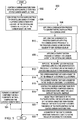
Figure 5 is an illustration of a flowchart of a method for forming a layered carbon fiber in accordance with an illustrative embodiment; -
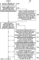
Figure 6 is an illustration of a flowchart of a method for forming a layered carbon fiber in accordance with an illustrative embodiment; -
Figure 7 is an illustration of an aircraft manufacturing and service method in the form of a block diagram in accordance with an illustrative embodiment; and -
Figure 8 is an illustration of an aircraft in the form of a block diagram in which an illustrative embodiment may be implemented. - The illustrative embodiments recognize and take into account one or more different considerations. For example, the illustrative embodiments recognize and take into account that carbon nanotube (CNT) yarn is a bundle of tangled carbon nanotubes without binder. The illustrative embodiments recognize and take into account that there are two conventional methods of forming carbon nanotube yarn. The illustrative embodiments recognize and take into account that one method to form carbon nanotube yarn is to draw it from a forest of vertically aligned carbon nanotubes, optionally twisting the yarn as it is pulled. The illustrative embodiments recognize and take into account that another method to form carbon nanotube yarn is wet spinning. The illustrative embodiments recognize and take into account that to use wet spinning, a stream of carbon nanotubes is injected in a solvent into a circulating bath of a fluid in which the solvent is soluble. The solvent disperses and the carbon nanotubes bunch together.
- Turning now to
Figure 1 , an illustration of a block diagram of a manufacturing environment in which a composite structure is manufactured is depicted in accordance with an illustrative embodiment. Inmanufacturing environment 100,layered carbon fiber 102 is generated. Layeredcarbon fiber 102 comprisessheath 104 ofcrystalline carbon 106 andcore 108 ofcarbon nanotube yarn 110. - Layered
carbon fiber 102 hasdiameter 112.Diameter 112 oflayered carbon fiber 102 has any desirable value. In some illustrative examples,diameter 112 oflayered carbon fiber 102 is in the range of 3 microns to 10 microns. -
Carbon nanotube yarn 110 has diameter 114. Diameter has any desirable value. In some illustrative examples, diameter 114 ofcarbon nanotube yarn 110 is in the range of 1.5 microns to 2.5 microns. - Layered
carbon fiber 102 is formed using layered carbonfiber forming process 116. Layered carbonfiber forming process 116 comprises coating 118carbon nanotube yarn 110 withpolyacrylonitrile 122 to form coatedcarbon nanotube yarn 124. In some illustrative examples,coating 118 is referred to asdip coating 125.Polyacrylonitrile 122 on coatedcarbon nanotube yarn 124 is converted tocrystalline carbon 106 to formlayered carbon fiber 102 withsheath 104 ofcrystalline carbon 106 andcore 108 ofcarbon nanotube yarn 110. - In some illustrative examples, converting
polyacrylonitrile 122 tocrystalline carbon 106 comprises applyingcarbonization process 126 to convert polyacrylonitrile 122 tocarbon layer 127, and applyinggraphitization process 128 to convertcarbon layer 127 tocrystalline carbon 106.Carbonization process 126 is performed attemperature 130. In some illustrative examples,temperature 130 ofcarbonization process 126 is in a range of 800 degrees Celsius to 1200 degrees Celsius. In some illustrative examples,temperature 130 is approximately 1000 degrees Celsius. -
Graphitization process 128 is performed attemperature 132. In some illustrative examples,temperature 132 is in the range of 1,200 degrees Celsius to 3,000 degrees Celsius. - In some illustrative examples, coating 118
carbon nanotube yarn 110 withpolyacrylonitrile 122 comprises sendingcarbon nanotube yarn 110 throughbath 134 ofpolyacrylonitrile 122. In these illustrative examples,temperature 136 ofpolyacrylonitrile 122 inbath 134 andspeed 138 ofcarbon nanotube yarn 110 passing throughbath 134 affect a thickness ofpolyacrylonitrile 122 on coatedcarbon nanotube yarn 124. Temperature ofpolyacrylonitrile 122 inbath 134 andspeed 138 ofcarbon nanotube yarn 110 passing throughbath 134 are adjusted to achieve a desired thickness ofpolyacrylonitrile 122 on coatedcarbon nanotube yarn 124. - Coated
carbon nanotube yarn 124 hasdiameter 140. In some illustrative examples, coatedcarbon nanotube yarn 110 hasdiameter 140 in the range of 5 microns to 13 microns. -
Layered carbon fiber 102 may be used to replace traditional carbon fibers in structural applications. For example,layered carbon fiber 102 may be used to replace traditional carbon fibers in composite materials. - In some illustrative examples,
carbon nanotube yarn 110 is propelled through layered carbonfiber forming process 116 usingrollers 142. In some illustrative examples, one ofrollers 142 is present incoating 118 process. In some illustrative examples, the next roller ofrollers 142 is positioned within or aftercarbonization process 126. When the next roller ofrollers 142 is positioned within or aftercarbonization process 126,rollers 142 do not displacepolyacrylonitrile 122 on coatedcarbon nanotube yarn 124. When the next roller ofrollers 142 is positioned within or aftercarbonization process 126,polyacrylonitrile 122 on coatedcarbon nanotube yarn 124 has solidified oncarbon nanotube yarn 110 before the next roller contactscarbon nanotube yarn 110. In some illustrative examples, the next rollercontacts carbon layer 127 aftercarbonization process 126. - As depicted, layered carbon
fiber forming process 116 is performed insystem 144.System 144 is configured to form layeredcarbon fiber 102.System 144 comprisesbath 134 ofpolyacrylonitrile 122,movement system 146,carbonization system 148, andgraphitization system 150. -
Movement system 146 is configured to movecarbon nanotube yarn 110 throughbath 134 ofpolyacrylonitrile 122.Carbonization system 148 is configured to receive coatedcarbon nanotube yarn 124 comprisingpolyacrylonitrile 122 on thecarbon nanotube yarn 110.Graphitization system 150 is configured to form layeredcarbon fiber 102 fromcarbon layer 127 oncarbon nanotube yarn 110. - As depicted,
movement system 146 comprisesrollers 142. In some illustrative examples, a roller ofrollers 142 is inbath 134 ofpolyacrylonitrile 122. - In some illustrative examples, a second roller of
rollers 142 is withincarbonization system 148. In some illustrative examples,carbonization system 148 is between the roller and a second roller ofrollers 142. - In some illustrative examples,
carbonization system 148 comprisesheater 152 configured to maintain a temperature in the range of 800 degrees Celsius to 1,200 degrees Celsius. In some illustrative examples,graphitization system 150 comprisesheater 154 configured to maintain a temperature in the range of 1,200 degrees Celsius to 3,000 degrees Celsius. - The illustration of
manufacturing environment 100 inFigure 1 is not meant to imply physical or architectural limitations to the manner in which an illustrative example may be implemented. Other components in addition to or in place of the ones illustrated may be used. Some components may be unnecessary. Also, the blocks are presented to illustrate some functional components. One or more of these blocks may be combined, divided, or combined and divided into different blocks when implemented in an illustrative example. - For example,
manufacturing environment 100 may further comprise manufacturing equipment forcarbon nanotube yarn 110. In other illustrative examples,carbon nanotube yarn 110 is manufactured outside ofmanufacturing environment 100. - As another example, although
bath 134 is depicted, any desirable system for performingcoating 118 may be used. In other illustrative examples, coating 118 is performed using a deposition system other thanbath 134. - Turning now to
Figure 2 , an illustration of a side view of a layered carbon fiber with a portion of a sheath cut away is depicted in accordance with an illustrative embodiment.Layered carbon fiber 200 is a physical implementation of layeredcarbon fiber 102 ofFigure 1 . -
Layered carbon fiber 200 comprisessheath 202 ofcrystalline carbon 204 andcore 206 ofcarbon nanotube yarn 208. As depicted, a portion ofsheath 202 is cut away to makecore 206 visible inFigure 2 . As depicted,layered carbon fiber 200 hasdiameter 210 andcarbon nanotube yarn 208 hasdiameter 212. In some illustrative examples,diameter 210 is approximately 2 microns. In some illustrative examples,diameter 212 is in the range of 5 microns to 13 microns. - Turning now to
Figure 3 , an illustration of a cross-sectional view of a layered carbon fiber is depicted in accordance with an illustrative embodiment.Layered carbon fiber 300 is a physical implementation of layeredcarbon fiber 102 ofFigure 1 . In some illustrative examples,layered carbon fiber 300 is the same as layeredcarbon fiber 200 ofFigure 2 . -
Layered carbon fiber 300 comprisessheath 302 ofcrystalline carbon 304 andcore 306 ofcarbon nanotube yarn 308. As depicted,layered carbon fiber 300 hasdiameter 310 andcarbon nanotube yarn 308 hasdiameter 312. In some illustrative examples,diameter 310 is approximately 2 microns. In some illustrative examples,diameter 312 is in the range of 5 microns to 13 microns. - Turning now to
Figure 4 , an illustration of a graphical depiction of a manufacturing environment in which a layered carbon fiber is manufactured is depicted in accordance with an illustrative embodiment.Manufacturing environment 400 is a representation ofmanufacturing environment 100 ofFigure 1 . -
Manufacturing environment 400 hascarbon nanotube yarn 402 that is supplied tosystem 403 performing layered carbonfiber forming process 404. As depicted,fiber forming process 404 comprises coating 408,carbonization process 412, andgraphitization process 418. As depicted,system 403 comprisesbath 422,carbonization system 424,graphitization system 426, andmovement system 428. -
Layered carbon fiber 406 is formed by coating 408carbon nanotube yarn 402 with polyacrylonitrile, formingcarbon layer 410 oncarbon nanotube yarn 402 by performingcarbonization process 412 on the polyacrylonitrile, and formingsheath 414 ofcrystalline carbon 416 oncarbon nanotube yarn 402 by performinggraphitization process 418 oncarbon layer 410. As depicted,coating 408 is performed inbath 422. -
Carbonization process 412 is performed at any desirable temperature to remove hydrogen and nitrogen atoms from the polyacrylonitrile.Carbonization process 412 is performed incarbonization system 424. In some illustrative examples, formingcarbon layer 410 comprises heating the polyacrylonitrile oncarbon nanotube yarn 402 at a temperature in the range of 800 degrees Celsius to 1200 degrees Celsius to remove hydrogen and nitrogen atoms and formcarbon layer 410 from the polyacrylonitrile oncarbon nanotube yarn 402. -
Graphitization process 418 is performed ingraphitization system 426.Graphitization process 418 is performed at any desirable temperature to crystalizecarbon layer 410. In some illustrative examples,graphitization process 418heats carbon layer 410 oncarbon nanotube yarn 402 at a temperature in the range of 1200 degrees Celsius to 3000 degrees Celsius. - As depicted,
coating 408 is performed usingroller 420. Although another roller is not depicted inmanufacturing environment 400, a second roller (not depicted) would be used to pullcarbon nanotube yarn 402 through layered carbonfiber forming process 404. In some illustrative examples, the second roller is positioned inside or followingcarbonization process 412. By the second roller being positioned after orinside carbonization process 412, the second roller (not depicted) does not undesirably remove polyacrylonitrile fromcarbon nanotube yarn 402. By the second roller being positioned after orinside carbonization process 412, the second roller (not depicted) contactscarbon nanotube yarn 402 when the coating of either polyacrylonitrile or carbon is firm oncarbon nanotube yarn 402. - Any desirable quantity of rollers is present to move
carbon nanotube yarn 402 through layered carbonfiber forming process 404. Also, the rollers may have any desirable locations withinsystem 403 configured to perform carbonfiber forming process 404.Roller 420 and any other rollers insystem 403 are components ofmovement system 428. - Turning now to
Figure 5 , an illustration of a flowchart of a method for forming a layered carbon fiber is depicted in accordance with an illustrative embodiment.Method 500 is an implementation of layered carbonfiber forming processing 116 ofFigure 1 .Method 500 may be used to createlayered carbon fiber 200 ofFigure 2 .Method 500 may be used to createlayered carbon fiber 300 ofFigure 3 .Method 500 may be implemented inmanufacturing environment 400 ofFigure 4 . -
Method 500 coats a carbon nanotube yarn with polyacrylonitrile to form a coated carbon nanotube yarn (operation 502).Method 500 converts the polyacrylonitrile to crystalline carbon to form a layered carbon fiber with a sheath of the crystalline carbon and a core of the carbon nanotube yarn (operation 504). Afterwards,method 500 terminates. - In some illustrative examples, converting the polyacrylonitrile to crystalline carbon comprises applying a carbonization process to convert the polyacrylonitrile to a carbon layer (operation 506) and applying a graphitization process to convert the carbon layer to the crystalline carbon (operation 508). In some illustrative examples, applying the carbonization process comprises applying the carbonization process at a temperature in a range of 800 degrees Celsius to 1,200 degrees Celsius (operation 510). In some illustrative examples, applying the graphitization process comprises applying the graphitization process at a temperature in the range of 1,200 degrees Celsius to 3,000 degrees Celsius (operation 512).
- In some illustrative examples, the carbon nanotube yarn has a diameter in the range of 1.5 microns to 2.5 microns (operation 514). In some illustrative examples, the layered carbon fiber has a diameter in the range of 3 microns to 10 microns (operation 516).
- In some illustrative examples coating the carbon nanotube yarn with polyacrylonitrile comprises sending the carbon nanotube yarn through a bath of polyacrylonitrile (operation 518). In some illustrative examples,
method 500 further comprises adjusting a temperature of the polyacrylonitrile in the bath and a speed of the carbon nanotube yarn passing through the bath to achieve a desired thickness of polyacrylonitrile on the coated carbon nanotube yarn (operation 520). In some illustrative examples, the coated carbon nanotube yarn has a diameter in the range of 5 microns to 13 microns (operation 522). In some illustrative examples,method 500 forms an aircraft component using a composite material comprising the layered carbon fiber (operation 524). - Turning now to
Figure 6 , an illustration of a flowchart of a method for forming a layered carbon fiber is depicted in accordance with an illustrative embodiment.Method 600 is an implementation of layered carbonfiber forming processing 116 ofFigure 1 .Method 600 may be used to createlayered carbon fiber 200 ofFigure 2 .Method 600 may be used to createlayered carbon fiber 300 ofFigure 3 .Method 600 may be implemented inmanufacturing environment 400 ofFigure 4 . -
Method 600 dip-coats a carbon nanotube yarn with polyacrylonitrile (operation 602).Method 600 forms a carbon layer on the carbon nanotube yarn by performing a carbonization process on the polyacrylonitrile (operation 604).Method 600 forms a sheath of crystalline carbon on the carbon nanotube yarn by performing a graphitization process on the carbon layer (operation 606). Afterwards,method 600 terminates. - In some illustrative examples, forming the carbon layer comprises heating the polyacrylonitrile on the carbon nanotube yarn at a temperature in the range of 800 degrees Celsius to 1,200 degrees Celsius to remove hydrogen and nitrogen atoms and form the carbon layer from the polyacrylonitrile on the carbon nanotube yarn (operation 608). In some illustrative examples, forming the sheath comprises heating the carbon layer on the carbon nanotube yarn at a temperature in the range of 1,200 degrees Celsius to 3,000 degrees Celsius (operation 610).
- In some illustrative examples, the carbon nanotube yarn has a diameter in the range of 1.5 microns to 2.5 microns (operation 612). In some illustrative examples, the sheath of crystalline carbon and the carbon nanotube yarn form a layered carbon fiber with a diameter in the range of 3 microns to 10 microns (operation 614).
- In some illustrative examples,
method 600 further comprises adjusting a temperature of polyacrylonitrile in a bath and a speed of the carbon nanotube yarn passing through the bath during the dip-coating to achieve a desired thickness of polyacrylonitrile on the carbon nanotube yarn (operation 616). In some illustrative examples, the carbon nanotube yarn and polyacrylonitrile together have a diameter in the range of 5 microns to 13 microns (operation 618). In some illustrative examples, forming an aircraft component using a composite material comprising the sheath of crystalline carbon on the carbon nanotube yarn (operation 620). - The flowcharts and block diagrams in the different depicted examples illustrate the architecture, functionality, and operation of some possible implementations of apparatus and methods in an illustrative example. In this regard, each block in the flowcharts or block diagrams may represent a module, a segment, a function, and/or a portion of an operation or step.
- In some alternative implementations of an illustrative example, the function or functions noted in the blocks may occur out of the order noted in the figures. For example, in some cases, two blocks shown in succession may be executed substantially concurrently, or the blocks may sometimes be performed in the reverse order, depending upon the functionality involved. Also, other blocks may be added, in addition to the illustrated blocks, in a flowchart or block diagram.
- In some illustrative examples, not all blocks of
method 500 ormethod 600 are performed. For example,operations 506 through 524 ofFigure 5 may be optional. As another example,operations 608 through 620 ofFigure 6 may be optional. - The illustrative examples of the present disclosure may be described in the context of aircraft manufacturing and
service method 700 as shown inFigure 7 andaircraft 800 as shown inFigure 8 . Turning first toFigure 7 , an illustration of an aircraft manufacturing and service method is depicted in accordance with an illustrative embodiment. During pre-production, aircraft manufacturing andservice method 700 may include specification anddesign 702 ofaircraft 800 inFigure 8 andmaterial procurement 704. - During production, component and
subassembly manufacturing 706 andsystem integration 708 ofaircraft 800 takes place. Thereafter,aircraft 800 may go through certification anddelivery 710 in order to be placed inservice 712. While inservice 712 by a customer,aircraft 800 is scheduled for maintenance andservice 714, which may include modification, reconfiguration, refurbishment, and other maintenance or service. - Each of the processes of aircraft manufacturing and
service method 700 may be performed or carried out by a system integrator, a third party, and/or an operator. In these examples, the operator may be a customer. For the purposes of this description, a system integrator may include, without limitation, any number of aircraft manufacturers or major-system subcontractors; a third party may include, without limitation, any number of vendors, subcontractors, or suppliers; and an operator may be an airline, a leasing company, a military entity, a service organization, and so on. - With reference now to
Figure 8 , an illustration of an aircraft is depicted in which an illustrative example may be implemented. In this example,aircraft 800 is produced by aircraft manufacturing andservice method 700 inFigure 7 and may includeairframe 802 with a plurality ofsystems 804 and interior 806. Examples ofsystems 804 include one or more ofpropulsion system 808,electrical system 810,hydraulic system 812, andenvironmental system 814. Any number of other systems may be included. Although an aerospace example is shown, different illustrative examples may be applied to other industries, such as other industries utilizing composite materials. - Although the illustrative examples for an illustrative embodiment are described with respect to an aircraft, an illustrative embodiment may be applied to other types of platforms. The platform may be, for example, a mobile platform, a stationary platform, a land-based structure, an aquatic-based structure, and a space-based structure. More specifically, the platform, may be a surface ship, a tank, a personnel carrier, a train, a spacecraft, a space station, a satellite, a submarine, an automobile, a power plant, a bridge, a dam, a house, a manufacturing facility, a building, and other suitable platforms.
- Apparatuses and methods embodied herein may be employed during at least one of the stages of aircraft manufacturing and
service method 700. One or more illustrative examples may be used during component andsubassembly manufacturing 706,system integration 708, or maintenance andservice 714 ofFigure 7 . For example,layered carbon fiber 102 formed by layered carbonfiber forming process 116 may be used to form a component ofaircraft 800, during component andsubassembly manufacturing 706. As another example,layered carbon fiber 102 formed by layered carbonfiber forming process 116 may be used to form a composite structure to be used as a replacement part during maintenance andservice 714 ofFigure 7 . - Apparatuses and methods embodied herein may be employed in manufacturing at least one component of
aircraft 800. For example,layered carbon fiber 102 formed by layered carbonfiber forming process 116 may be used in a composite material in a component of one ofairframe 802 or interior 806. - The illustrative examples provide a carbon fiber with a thin carbon nanotube (CNT) yarn at its core. The carbon nanotube (CNT) yarn may be thinner than conventionally used carbon nanotube yarn. The illustrative examples provide a method to be performed on a carbon nanotube yarn. In some illustrative examples, the carbon nanotube yarn has a diameter approximately 2 microns.
- The carbon nanotube yarn is drawn through a bath of PAN at a given speed to coat it with an engineered thickness of PAN. The method then takes that carbon nanotube yarn and PAN coating through carbonization and graphitization ovens to convert the PAN to graphitic carbon.
- The illustrative examples present a layered carbon fiber that is a high modulus carbon fiber. In some illustrative examples, the thickness of the layered carbon fiber is in the 3 micron to 10 micron diameter range.
- The illustrative examples present a layered carbon fiber with little to no amorphous carbon. By reducing the amorphous carbon layered carbon fiber of the illustrative examples has a higher modulus than conventional carbon fibers with amorphous carbon centers.
- The layered carbon fiber comprises a core of graphitic carbon in the form of carbon nanotubes, to increase the modulus of the fiber. Replacing the amorphous carbon of conventional carbon fibers with carbon nanotubes (CNTs) will increase the modulus of each layered carbon fiber relative to a conventional carbon fiber. Increasing the modulus of fibers used in a composite also increases the modulus of the composite laminate. Using layered carbon fibers may also reduce the weight of the composite laminate as carbon nanotubes (CNTs) are less dense than amorphous carbon.
- The layered carbon fibers can be used as a replacement for traditional carbon fibers in composite prepregs and resin infusion carbon blanks. The insertion of the layered carbon fibers presents no change to processing of composite materials. The improved properties of the layered carbon fiber are imparted to a composite material including the layered carbon fiber.
- The present apparatus and method is also referred to in the following clauses which are not to be confused with the claims.
- A1. A method (500) comprising:
- coating (502) a carbon nanotube yarn (110) with polyacrylonitrile (122) to form a coated carbon nanotube yarn (124); and
- converting (504) the polyacrylonitrile (122) to crystalline carbon (106) to form a layered carbon fiber (102) with a sheath (104) of the crystalline carbon (106) and a core (108) of the carbon nanotube yarn.
- A2. There is also provided, the method (500) of paragraph A1, wherein converting the polyacrylonitrile (122) to crystalline carbon (106) comprises:
- applying (506) a carbonization process (126) to convert the polyacrylonitrile (122) to a carbon layer (127); and
- applying (508) a graphitization process (128) to convert the carbon layer (127) to the crystalline carbon (106).
- A3. There is also provided, the method (500) of paragraph A2, wherein applying (510) the carbonization process (126) comprises applying the carbonization process (126) at a temperature (130) in a range of 800 degrees Celsius to 1,200 degrees Celsius.
- A4. There is also provided, the method (500) of paragraph A2, wherein applying (512) the graphitization process (128) comprises applying the graphitization process (128) at a temperature (132) in the range of 1,200 degrees Celsius to 3,000 degrees Celsius.
- A5. There is also provided, the method (500) of paragraph A1, wherein (514) the carbon nanotube yarn (110) has a diameter (114) in the range of 1.5 microns to 2.5 microns.
- A6. There is also provided, the method (500) of paragraph A1, wherein (516) the layered carbon fiber (102) has a diameter (112) in the range of 3 microns to 10 microns.
- A7. There is also provided, the method (500) of paragraph A1, wherein (518) coating the carbon nanotube yarn (110) with polyacrylonitrile (122) comprises sending the carbon nanotube yarn (110) through a bath (134) of polyacrylonitrile (122).
- A8. There is also provided, the method (500) of paragraph A7 further comprising:
adjusting (520) a temperature (136) of the polyacrylonitrile (122) in the bath (134) and a speed (138) of the carbon nanotube yarn (110) passing through the bath (134) to achieve a desired thickness of polyacrylonitrile (122) on the coated carbon nanotube yarn (124). - A9. There is also provided, the method (500) of paragraph A8, wherein (522) the coated carbon nanotube yarn (124) has a diameter (140) in the range of 5 microns to 13 microns.
- A10. There is also provided, the method (500) of paragraph A1 further comprising:
forming (524) an aircraft component using a composite material comprising the layered carbon fiber (102). - According to a further aspect of the present method, there is provided:
- B1. A method (600) comprising:
- dip-coating (602) a carbon nanotube yarn (110) with polyacrylonitrile (122);
- forming (604) a carbon layer (127) on the carbon nanotube yarn (110) by performing a carbonization process (126) on the polyacrylonitrile (122); and
- forming (606) a sheath (104) of crystalline carbon (106) on the carbon nanotube yarn (110) by performing a graphitization process (128) on the carbon layer (127).
- B2. There is also provided, the method (600) of paragraph Bl, wherein forming the carbon layer (127) comprises:
heating (608) the polyacrylonitrile (122) on the carbon nanotube yarn (110) at a temperature (130) in the range of 800 degrees Celsius to 1,200 degrees Celsius to remove hydrogen and nitrogen atoms and form the carbon layer (127) from the polyacrylonitrile (122) on the carbon nanotube yarn (110). - B3. There is also provided, the method (600) of paragraph Bl, wherein forming the sheath (104) comprises:
heating (610) the carbon layer (127) on the carbon nanotube yarn (110) at a temperature (132) in the range of 1,200 degrees Celsius to 3,000 degrees Celsius. - B4. There is also provided, the method (600) of paragraph Bl, wherein (612) the carbon nanotube yarn (110) has a diameter (114) in the range of 1.5 microns to 2.5 microns.
- B5. There is also provided, the method (600) of paragraph Bl, wherein (614) the sheath (104) of crystalline carbon (106) and the carbon nanotube yarn (110) form a layered carbon fiber (102) with a diameter (112) in the range of 3 microns to 10 microns.
- B6. There is also provided, the method (600) of paragraph Bl, further comprising:
adjusting (616) a temperature (136) of polyacrylonitrile (122) in a bath (134) and a speed (138) of the carbon nanotube yarn passing through the bath (134) during the dip-coating (125) to achieve a desired thickness of polyacrylonitrile (122) on the carbon nanotube yarn (110). - B7. There is also provided, the method (600) of paragraph Bl, wherein (618) the carbon nanotube yarn (110) and polyacrylonitrile (122) together have a diameter (140) in the range of 5 microns to 13 microns.
- B8. There is also provided, the method (600) of paragraph B1 further comprising:
forming (620) an aircraft component using a composite material comprising the sheath (104) of crystalline carbon (106) on the carbon nanotube yarn (110). - According to a further aspect of the present apparatus, there is provided:
- C1. A layered carbon fiber (102) comprising:
- a sheath (104) of crystalline carbon (106); and
- a core (108) of carbon nanotube yarn (110).
- C2. There is also provided, the layered carbon fiber (102) of paragraph C1, wherein a diameter (112) of the layered carbon fiber (102) is in the range of 3 microns to 10 microns.
- C3. There is also provided, the layered carbon fiber (102) of paragraph C1, wherein a diameter (114) of the carbon nanotube yarn (110) of the core (108) is in the range of 1.5 microns to 2.5 microns.
- C4. There is also provided, the layered carbon fiber (102) of paragraph C1, wherein the layered carbon fiber (102) is a component of a composite material forming an aircraft component.
- According to a further aspect of the present system, there is provided:
- D1. A system (144) configured to form a layered carbon fiber (102), the system (144) comprising:
- a bath (134) of polyacrylonitrile (122);
- a movement system (146) configured to move a carbon nanotube yarn (110) through the bath (134) of polyacrylonitrile (122);
- a carbonization system (148) configured to receive a coated carbon nanotube yarn (124) comprising polyacrylonitrile (122) on the carbon nanotube yarn (110); and
- a graphitization system (150) configured to form a layered carbon fiber (102) from a carbon layer (127) on the carbon nanotube yarn (110).
- D2. There is also provided, the system (144) of paragraph Dl, wherein the movement system (146) comprises rollers (142).
- D3. There is also provided, the system (144) of paragraph 24, wherein a roller (420) of the rollers (142) is in the bath (134) of polyacrylonitrile (122).
- D4. There is also provided, the system (144) of paragraph D3, wherein a second roller of the rollers (142) is within the carbonization system (148).
- D5. There is also provided, the system (144) of paragraph D3, wherein the carbonization system (148) is between the roller (420) and a second roller of the rollers (142).
- D6. There is also provided, the system (144) of paragraph D1, wherein the carbonization system (148) comprises a heater (152) configured to maintain a temperature (130) in the range of 800 degrees Celsius to 1,200 degrees Celsius.
- D7. There is also provided, the system (144) of paragraph Dl, wherein the graphitization system (150) comprises a heater (154) configured to maintain a temperature (132) in the range of 1,200 degrees Celsius to 3,000 degrees Celsius.
- The description of the different illustrative embodiments has been presented for purposes of illustration and description, and is not intended to be exhaustive or limited to the embodiments in the form disclosed. Many modifications and variations will be apparent to those of ordinary skill in the art. Further, different illustrative embodiments may provide different features as compared to other illustrative embodiments. The embodiment or embodiments selected are chosen and described in order to best explain the principles of the embodiments, the practical application, and to enable others of ordinary skill in the art to understand the disclosure for various embodiments with various modifications as are suited to the particular use contemplated.
Claims (15)
- A method (500) comprising:coating (502) a carbon nanotube yarn (110) with polyacrylonitrile (122) to form a coated carbon nanotube yarn (124); andconverting (504) the polyacrylonitrile (122) to crystalline carbon (106) to form a layered carbon fiber (102) with a sheath (104) of the crystalline carbon (106) and a core (108) of the carbon nanotube yarn.
- The method (500) of claim 1, wherein converting the polyacrylonitrile (122) to crystalline carbon (106) comprises:applying (506) a carbonization process (126) to convert the polyacrylonitrile (122) to a carbon layer (127); andapplying (508) a graphitization process (128) to convert the carbon layer (127) to the crystalline carbon (106).
- The method (500) of claim 2, wherein applying (510) the carbonization process (126) comprises applying the carbonization process (126) at a temperature (130) in a range of 800 degrees Celsius to 1,200 degrees Celsius.
- The method (500) of claim 2, wherein applying (512) the graphitization process (128) comprises applying the graphitization process (128) at a temperature (132) in the range of 1,200 degrees Celsius to 3,000 degrees Celsius.
- The method (500) of claim 1, wherein (518) coating the carbon nanotube yarn (110) with polyacrylonitrile (122) comprises sending the carbon nanotube yarn (110) through a bath (134) of polyacrylonitrile (122).
- The method (500) of claim 5 further comprising:
adjusting (520) a temperature (136) of the polyacrylonitrile (122) in the bath (134) and a speed (138) of the carbon nanotube yarn (110) passing through the bath (134) to achieve a desired thickness of polyacrylonitrile (122) on the coated carbon nanotube yarn (124). - A layered carbon fiber (102) comprising:a sheath (104) of crystalline carbon (106); anda core (108) of carbon nanotube yarn (110).
- The layered carbon fiber (102) of claim 7, wherein a diameter (112) of the layered carbon fiber (102) is in the range of 3 microns to 10 microns.
- A system (144) configured to form a layered carbon fiber (102), the system (144) comprising:a bath (134) of polyacrylonitrile (122);a movement system (146) configured to move a carbon nanotube yarn (110) through the bath (134) of polyacrylonitrile (122);a carbonization system (148) configured to receive a coated carbon nanotube yarn (124) comprising polyacrylonitrile (122) on the carbon nanotube yarn (110); anda graphitization system (150) configured to form a layered carbon fiber (102) from a carbon layer (127) on the carbon nanotube yarn (110).
- The system (144) of claim 9, wherein the movement system (146) comprises rollers (142).
- The system (144) of claim 10, wherein a roller (420) of the rollers (142) is in the bath (134) of polyacrylonitrile (122).
- The system (144) of claim 11, wherein a second roller of the rollers (142) is within the carbonization system (148).
- The system (144) of claim 11, wherein the carbonization system (148) is between the roller (420) and a second roller of the rollers (142).
- The system (144) of claim 9, wherein the carbonization system (148) comprises a heater (152) configured to maintain a temperature (130) in the range of 800 degrees Celsius to 1,200 degrees Celsius.
- The system (144) of claim 9, wherein the graphitization system (150) comprises a heater (154) configured to maintain a temperature (132) in the range of 1,200 degrees Celsius to 3,000 degrees Celsius.
Applications Claiming Priority (1)
| Application Number | Priority Date | Filing Date | Title |
|---|---|---|---|
| US15/978,011 US10533266B2 (en) | 2018-05-11 | 2018-05-11 | Layered carbon fiber |
Publications (1)
| Publication Number | Publication Date |
|---|---|
| EP3567140A1 true EP3567140A1 (en) | 2019-11-13 |
Family
ID=66223572
Family Applications (1)
| Application Number | Title | Priority Date | Filing Date |
|---|---|---|---|
| EP19165301.3A Pending EP3567140A1 (en) | 2018-05-11 | 2019-03-26 | Layered carbon fiber |
Country Status (2)
| Country | Link |
|---|---|
| US (1) | US10533266B2 (en) |
| EP (1) | EP3567140A1 (en) |
Cited By (1)
| Publication number | Priority date | Publication date | Assignee | Title |
|---|---|---|---|---|
| CN120719460A (en) * | 2025-08-15 | 2025-09-30 | 鸿瑞新材(山西)科技有限公司 | A method for preparing high-purity viscose-based graphite felt |
Families Citing this family (1)
| Publication number | Priority date | Publication date | Assignee | Title |
|---|---|---|---|---|
| CN112853562A (en) * | 2020-03-30 | 2021-05-28 | 浙江龙仕达科技股份有限公司 | Preparation method of natural degradable covered yarn |
Citations (5)
| Publication number | Priority date | Publication date | Assignee | Title |
|---|---|---|---|---|
| CN101956252A (en) * | 2010-09-19 | 2011-01-26 | 东华大学 | Method for preparing carbon fibers from boron modified polyacrylonitrile precursors |
| CN102181964A (en) * | 2011-04-02 | 2011-09-14 | 东华大学 | Method for preparing polyacrylonitrile based carbon fiber |
| WO2012108607A1 (en) * | 2011-02-07 | 2012-08-16 | 숭실대학교 산학협력단 | Manufactured carbon nanotube fibers |
| US20130149522A1 (en) * | 2011-12-10 | 2013-06-13 | The Boeing Company | Fiber with Gradient Properties and Method of Making the Same |
| EP2857354A1 (en) * | 2012-05-30 | 2015-04-08 | Soongsil University | Method for preparing carbon nanotube fiber reinforced with carbon precursor |
Family Cites Families (3)
| Publication number | Priority date | Publication date | Assignee | Title |
|---|---|---|---|---|
| US6451420B1 (en) * | 2000-03-17 | 2002-09-17 | Nanofilm, Ltd. | Organic-inorganic hybrid polymer and method of making same |
| US7618679B2 (en) * | 2007-08-27 | 2009-11-17 | Intel Corporation | Thermally and electrically conductive structure, method of applying a carbon coating to same, and method of reducing a contact resistance of same |
| US9683310B2 (en) * | 2011-12-10 | 2017-06-20 | The Boeing Company | Hollow fiber with gradient properties and method of making the same |
-
2018
- 2018-05-11 US US15/978,011 patent/US10533266B2/en active Active
-
2019
- 2019-03-26 EP EP19165301.3A patent/EP3567140A1/en active Pending
Patent Citations (5)
| Publication number | Priority date | Publication date | Assignee | Title |
|---|---|---|---|---|
| CN101956252A (en) * | 2010-09-19 | 2011-01-26 | 东华大学 | Method for preparing carbon fibers from boron modified polyacrylonitrile precursors |
| WO2012108607A1 (en) * | 2011-02-07 | 2012-08-16 | 숭실대학교 산학협력단 | Manufactured carbon nanotube fibers |
| CN102181964A (en) * | 2011-04-02 | 2011-09-14 | 东华大学 | Method for preparing polyacrylonitrile based carbon fiber |
| US20130149522A1 (en) * | 2011-12-10 | 2013-06-13 | The Boeing Company | Fiber with Gradient Properties and Method of Making the Same |
| EP2857354A1 (en) * | 2012-05-30 | 2015-04-08 | Soongsil University | Method for preparing carbon nanotube fiber reinforced with carbon precursor |
Cited By (1)
| Publication number | Priority date | Publication date | Assignee | Title |
|---|---|---|---|---|
| CN120719460A (en) * | 2025-08-15 | 2025-09-30 | 鸿瑞新材(山西)科技有限公司 | A method for preparing high-purity viscose-based graphite felt |
Also Published As
| Publication number | Publication date |
|---|---|
| US20190345645A1 (en) | 2019-11-14 |
| US10533266B2 (en) | 2020-01-14 |
Similar Documents
| Publication | Publication Date | Title |
|---|---|---|
| US8999453B2 (en) | Carbon nanotube-infused fiber materials containing parallel-aligned carbon nanotubes, methods for production thereof, and composite materials derived therefrom | |
| US7867468B1 (en) | Multiscale carbon nanotube-fiber reinforcements for composites | |
| AU2011205649B2 (en) | CNT-infused fiber as a self shielding wire for enhanced power transmission line | |
| US20120000691A1 (en) | Cnt-infused fiber as a self shielding wire for enhanced power transmission line | |
| US20160347009A1 (en) | Method of manufacturing a fibrous material preimpregnated with thermoplastic polymer using an aqueous dispersion of polymer | |
| EP3567140A1 (en) | Layered carbon fiber | |
| JP2009535530A (en) | Modification of reinforcing fiber tows used in composites using nano-reinforcing materials | |
| CN106378984B (en) | Light flexible high heat conducting nano carbon composite membrane and preparation method thereof | |
| US20230232719A1 (en) | Piezoelectric fiber having swiss-roll structure, and preparation method therefor and use thereof | |
| US11525193B2 (en) | Method and apparatus for manufacturing carbon fibers | |
| Kolobkov et al. | Development of carbon fiber production technologies. A review | |
| CN115677358B (en) | System and method for coating ceramic fibers | |
| Chawla | Polymer matrix composites | |
| US20120149802A1 (en) | Composites having distortional resin coated fibers | |
| CN111117151A (en) | Thermoplastic composite material low temperature liquid oxygen storage tank cylinder with gradient resin layer and its manufacturing method | |
| JP4832208B2 (en) | Manufacturing method of prepreg with excellent uniformity | |
| CN120738875B (en) | Preparation equipment and method of carbon nano tube reinforced thermoplastic composite wire | |
| US20250171310A1 (en) | Process for Manufacture of Carbon Nanotube Tape-Like Prepeg for Enhanced Composite Properties | |
| WO2015016071A1 (en) | SiC FIBER-REINFORCED SiC COMPOSITE MATERIAL AND PRODUCTION METHOD FOR SiC FIBER-REINFORCED SiC COMPOSITE MATERIAL | |
| US12492506B2 (en) | Fabricating methods and apparatuses for a multilayered, nanoparticle-coated fiber material | |
| Martins et al. | 4 Carbon nanotube-based materials for space applications | |
| Wang et al. | Graphene‐Skinned Alumina Fiber: Continuously Scalable Fabrication and Its Electrothermal Application in Fiber‐Reinforced Polymer Composites | |
| Rodríguez et al. | Mechanical Properties of Fibers Coated by Atomic Layer Deposition for Polymer-Matrix Composites with Enhanced Thermal and Ultraviolet Resistance | |
| CN121325345A (en) | Braided reinforced guidance optical cable and preparation method thereof |
Legal Events
| Date | Code | Title | Description |
|---|---|---|---|
| PUAI | Public reference made under article 153(3) epc to a published international application that has entered the european phase |
Free format text: ORIGINAL CODE: 0009012 |
|
| STAA | Information on the status of an ep patent application or granted ep patent |
Free format text: STATUS: REQUEST FOR EXAMINATION WAS MADE |
|
| 17P | Request for examination filed |
Effective date: 20190326 |
|
| AK | Designated contracting states |
Kind code of ref document: A1 Designated state(s): AL AT BE BG CH CY CZ DE DK EE ES FI FR GB GR HR HU IE IS IT LI LT LU LV MC MK MT NL NO PL PT RO RS SE SI SK SM TR |
|
| AX | Request for extension of the european patent |
Extension state: BA ME |
|
| RBV | Designated contracting states (corrected) |
Designated state(s): AL AT BE BG CH CY CZ DE DK EE ES FI FR GB GR HR HU IE IS IT LI LT LU LV MC MK MT NL NO PL PT RO RS SE SI SK SM TR |
|
| RAP3 | Party data changed (applicant data changed or rights of an application transferred) |
Owner name: THE BOEING COMPANY |
|
| STAA | Information on the status of an ep patent application or granted ep patent |
Free format text: STATUS: EXAMINATION IS IN PROGRESS |
|
| 17Q | First examination report despatched |
Effective date: 20230404 |