EP3566915B1 - Locking and unlocking fixture capable of adaptive position adjustment - Google Patents
Locking and unlocking fixture capable of adaptive position adjustment Download PDFInfo
- Publication number
- EP3566915B1 EP3566915B1 EP18736749.5A EP18736749A EP3566915B1 EP 3566915 B1 EP3566915 B1 EP 3566915B1 EP 18736749 A EP18736749 A EP 18736749A EP 3566915 B1 EP3566915 B1 EP 3566915B1
- Authority
- EP
- European Patent Office
- Prior art keywords
- fixture
- locking
- unlocking
- base
- segment
- Prior art date
- Legal status (The legal status is an assumption and is not a legal conclusion. Google has not performed a legal analysis and makes no representation as to the accuracy of the status listed.)
- Active
Links
Images


Classifications
-
- B—PERFORMING OPERATIONS; TRANSPORTING
- B60—VEHICLES IN GENERAL
- B60K—ARRANGEMENT OR MOUNTING OF PROPULSION UNITS OR OF TRANSMISSIONS IN VEHICLES; ARRANGEMENT OR MOUNTING OF PLURAL DIVERSE PRIME-MOVERS IN VEHICLES; AUXILIARY DRIVES FOR VEHICLES; INSTRUMENTATION OR DASHBOARDS FOR VEHICLES; ARRANGEMENTS IN CONNECTION WITH COOLING, AIR INTAKE, GAS EXHAUST OR FUEL SUPPLY OF PROPULSION UNITS IN VEHICLES
- B60K1/00—Arrangement or mounting of electrical propulsion units
- B60K1/04—Arrangement or mounting of electrical propulsion units of the electric storage means for propulsion
-
- B—PERFORMING OPERATIONS; TRANSPORTING
- B60—VEHICLES IN GENERAL
- B60L—PROPULSION OF ELECTRICALLY-PROPELLED VEHICLES; SUPPLYING ELECTRIC POWER FOR AUXILIARY EQUIPMENT OF ELECTRICALLY-PROPELLED VEHICLES; ELECTRODYNAMIC BRAKE SYSTEMS FOR VEHICLES IN GENERAL; MAGNETIC SUSPENSION OR LEVITATION FOR VEHICLES; MONITORING OPERATING VARIABLES OF ELECTRICALLY-PROPELLED VEHICLES; ELECTRIC SAFETY DEVICES FOR ELECTRICALLY-PROPELLED VEHICLES
- B60L53/00—Methods of charging batteries, specially adapted for electric vehicles; Charging stations or on-board charging equipment therefor; Exchange of energy storage elements in electric vehicles
- B60L53/80—Exchanging energy storage elements, e.g. removable batteries
-
- B—PERFORMING OPERATIONS; TRANSPORTING
- B60—VEHICLES IN GENERAL
- B60K—ARRANGEMENT OR MOUNTING OF PROPULSION UNITS OR OF TRANSMISSIONS IN VEHICLES; ARRANGEMENT OR MOUNTING OF PLURAL DIVERSE PRIME-MOVERS IN VEHICLES; AUXILIARY DRIVES FOR VEHICLES; INSTRUMENTATION OR DASHBOARDS FOR VEHICLES; ARRANGEMENTS IN CONNECTION WITH COOLING, AIR INTAKE, GAS EXHAUST OR FUEL SUPPLY OF PROPULSION UNITS IN VEHICLES
- B60K1/00—Arrangement or mounting of electrical propulsion units
- B60K1/04—Arrangement or mounting of electrical propulsion units of the electric storage means for propulsion
- B60K2001/0455—Removal or replacement of the energy storages
-
- Y—GENERAL TAGGING OF NEW TECHNOLOGICAL DEVELOPMENTS; GENERAL TAGGING OF CROSS-SECTIONAL TECHNOLOGIES SPANNING OVER SEVERAL SECTIONS OF THE IPC; TECHNICAL SUBJECTS COVERED BY FORMER USPC CROSS-REFERENCE ART COLLECTIONS [XRACs] AND DIGESTS
- Y02—TECHNOLOGIES OR APPLICATIONS FOR MITIGATION OR ADAPTATION AGAINST CLIMATE CHANGE
- Y02T—CLIMATE CHANGE MITIGATION TECHNOLOGIES RELATED TO TRANSPORTATION
- Y02T10/00—Road transport of goods or passengers
- Y02T10/60—Other road transportation technologies with climate change mitigation effect
- Y02T10/70—Energy storage systems for electromobility, e.g. batteries
-
- Y—GENERAL TAGGING OF NEW TECHNOLOGICAL DEVELOPMENTS; GENERAL TAGGING OF CROSS-SECTIONAL TECHNOLOGIES SPANNING OVER SEVERAL SECTIONS OF THE IPC; TECHNICAL SUBJECTS COVERED BY FORMER USPC CROSS-REFERENCE ART COLLECTIONS [XRACs] AND DIGESTS
- Y02—TECHNOLOGIES OR APPLICATIONS FOR MITIGATION OR ADAPTATION AGAINST CLIMATE CHANGE
- Y02T—CLIMATE CHANGE MITIGATION TECHNOLOGIES RELATED TO TRANSPORTATION
- Y02T10/00—Road transport of goods or passengers
- Y02T10/60—Other road transportation technologies with climate change mitigation effect
- Y02T10/7072—Electromobility specific charging systems or methods for batteries, ultracapacitors, supercapacitors or double-layer capacitors
Definitions
- the invention belongs to the field of new energy vehicles, and particularly provides a locking and unlocking fixture capable of adaptive position adjustment.
- chassis-type battery swap structure has the characteristics of short replacement time and easy automated operation due to the replacement of the entire battery, and therefore has increasingly become a hot technology in the industry research. Due to the heavy weight of the chassis battery swap type power battery, multiple locking points are required to lock and unlock same. In general, an automated unlocking apparatus is used to unlock multiple locking mechanisms at the same time, which presents a great challenge to the adaptability of the locking and unlocking fixture.
- the locking and unlocking fixture and a service object thereof often require high machining precision, which inevitably increases the production cost.
- CN 203 543 623 U relates to a battery locking mechanism applied to a battery replacing system of an electric car chassis.
- the battery locking mechanism comprises a hanging buckle, a spin lock maintaining box, a center pull shaft, a lifting pin, a bayonet lock and a drive shaft.
- the drive shaft drives a key to clamp a clamping groove and abut against the lifting pin so that the center pull shaft arranged in the spin lock maintaining box can be driven to rotate, and the bayonet lock arranged on the center pull shaft can be driven to rotate into a first limiting groove in a lower cover of the spin lock maintaining box to lock the center pull shaft.
- EP 3 552 855 A1 relates to a circumferential locking mechanism, a battery securing device comprising same, a battery pack, and a vehicle are provided.
- the circumferential locking mechanism comprises: a first component, the first component comprising a first body and pins extending from the first body in an axial direction, the pins being distributed on the first body along a first circumference; a second component, the second component comprising a second body and a limiting face on the second body, the limiting face extending in a circumferential direction and comprising segments, the radius of the limiting face tapering in both the axial and circumferential directions at the segments; and a third component for impelling the first component to engage with the second component, wherein the first component and the second component are arranged such that the first circumference and the limiting face are coaxial, and when the first component is engaged with the second component, the pins abut against the limiting face.
- the pins can be fitted to the limiting face by means of the foregoing structure
- the battery locking mechanism comprises a hanging fastener, a spin lock retaining box, a central pulling shaft and a manipulator, wherein the hanging fastener is fixedly arranged on an electric automobile chassis and is provided with a clamping groove; the spin lock retaining box is fixedly arranged on a battery; the central pulling shaft is rotatably installed in the spin lock retaining box, one end of the central pulling shaft is provided with a first hanging pin, the first hanging pin can enter the clamping groove, the first hanging pin and the hanging fastener are locked with each other after the first hanging pin rotates forwards, the first hanging pin and the hanging fastener are unlocked after the first hanging pin rotates reversely, and the other end of the central pulling shaft is provided with a second hanging pin; and the manipulator is arranged in an manner that the manipulator can be lifted up and lowered down relative to the spin lock retaining box, the manipulator is provided with a locking groove which
- CN 202 743 032 U fails to provide an additional limiting mechanism received in the manipulator 140 to effectively reduce the requirements for the machining and installation precision of the locking and unlocking device for the power battery.
- the invention provides a locking and unlocking fixture capable of adaptive position adjustment for locking and unlocking a power battery installed to an electric vehicle as defined by claim 1.
- the base comprises a first columnar segment and a second columnar segment, wherein the second columnar segment is a prismatic segment, which is received in a first sliding segment of the fixture sleeve in a clearance fit manner.
- a first spring is sheathed over the fixture sleeve corresponding to the first sliding segment, the first spring is further connected to the first columnar segment, and in the case where an external force is removed, the first spring enables the fixture sleeve to return to an initial position of the fixture sleeve relative to the base.
- the locking and unlocking fixture further comprises a first limiting mechanism, which enables the fixture sleeve to float in a vertical direction relative to the base as the driving device moves the base in the vertical direction.
- the first limiting mechanism comprises: a first strip-shaped hole provided in the prismatic segment; a first radial hole provided in the first sliding segment; and a first connecting rod connected to the first strip-shaped hole and the first radial hole, respectively, wherein the first connecting rod is slidable within a hole length range of the first strip-shaped hole, such that the fixture sleeve is floatable relative to the base within the hole length range of the first strip-shaped hole.
- the locking and unlocking fixture further comprises a second limiting mechanism received in a second sliding segment of the fixture sleeve, wherein the second limiting mechanism is capable of jacking up a threaded rod of a locking device of the power battery corresponding to the locking and unlocking fixture during a process in which the driving device moves the base in the vertical direction.
- the top of the fixture sleeve is provided with a connecting structure which is able to match and be butt against the threaded rod of the locking device of the power battery.
- the second limiting mechanism comprises: a push rod which received in the second sliding segment, and is slidable in an axial direction of the fixture sleeve; a second strip-shaped hole provided in the push rod; a second radial hole provided in the second sliding segment; and a second connecting rod connected to the second strip-shaped hole and the second radial hole, respectively, wherein the second connecting rod is slidable within a hole length range of the second strip-shaped hole, such that the fixture sleeve is floatable relative to the push rod within the hole length range of the second strip-shaped hole.
- a second spring is sheathed over the push rod, and in the case where an external force is removed, the second spring enables the push rod to return to an initial position relative to the fixture sleeve.
- the second spring is axially provided between the push rod and the second connecting rod, and in the case where an external force is removed, the second connecting rod is able to abut against the end of the second strip-shaped hole that is close to the base.
- a clearance fit is formed between the fixture sleeve and the base, and the fixture sleeve can slide up and down and float horizontally relative to the base by providing a first spring between the fixture sleeve and the base, such that the fixture sleeve can match the locking device of the power battery even if there is a certain positioning error when the fixture sleeve is engaged with the locking device, and the fixture sleeve can return to an initial position under the action of the first spring when the fixture sleeve is disengaged from the locking device of the power battery.
- the locking and unlocking fixture of the invention it is not necessary for the locking and unlocking fixture of the invention to provide high-precision machining and installation to enable an automated unlocking apparatus to successfully unlock the power battery.
- the terms “install”, “couple” and “connect” are to be understood in a broad sense, for example, it may be a fixed connection, a detachable connection, or an integral connection; a mechanical connection or an electrical connection; a direct connection or an indirect connection via an intermediate medium, or a communication between the interiors of two elements, unless expressly specified and defined otherwise.
- install may be a fixed connection, a detachable connection, or an integral connection
- a mechanical connection or an electrical connection a direct connection or an indirect connection via an intermediate medium, or a communication between the interiors of two elements, unless expressly specified and defined otherwise.
- the specific meaning of the above terms in the invention can be interpreted according to the specific situation.
- the locking and unlocking fixture capable of adaptive position adjustment of the invention is mainly used for locking and unlocking a chassis-type power battery installed on a chassis of the electric vehicle or a battery swap station for the electric vehicle, in particular, for unlocking a power battery which has been fixedly installed, and the locking and unlocking fixture of the invention has significant advantages over the existing locking and unlocking devices.
- the details are as follows:
- the locking and unlocking fixture capable of adaptive position adjustment of the invention mainly comprises a fixture sleeve 1, a first spring 2, a base 3 and a spring pusher.
- the fixture sleeve 1 is provided with a first radial hole 11, a second radial hole 12 and a connecting structure 13.
- the base 3 comprises a first columnar segment and a second columnar segment, for example, the first columnar segment may be a lower cylindrical segment 31 in Fig. 1 , and the second columnar segment may be an upper prismatic segment in Fig. 1 (taking a square columnar (quadrangular prismatic) segment 32 as an example).
- the square columnar segment 32 is provided with a first strip-shaped hole 321, through which first strip-shaped hole 321 the first connecting rod 4 installed therein can be moved up and down relative to the base 3 in the length direction of the hole.
- the spring pusher mainly comprises a push rod 5, a second spring 6 and a second connecting rod 7.
- the push rod 5 is provided with a second strip-shaped hole 51, through which second strip-shaped hole 51 the second connecting rod 7 installed therein can be moved up and down relative to the push rod 5 in the length direction of the hole.
- the second spring 6 is provided between the push rod 5 and the second connecting rod 7, and the second connecting rod 7 is pushed by the second spring 6 to the lowermost end of the second strip-shaped hole 51 in a normal state.
- the first connecting rod 4 is also installed into the first radial hole 11, and when the fixture sleeve 1 and the base 3 are connected via the first connecting rod 4, the fixture sleeve 1 can slide up and down relative to the base 3 as the first sliding rod 4 slides in the hole length direction of the first strip-shaped hole 321, the size of the opening of the first strip-shaped hole 321 in the vertical direction can limit the length of the relative sliding distance between the fixture sleeve 1 and the base 3, so that the first radial hole 11, the first strip-shaped hole 321 and the first connecting rod 4 together constitute the first limiting mechanism described in the claims.
- the fixture sleeve 1 and the base 3 preferably form a clearance fit in the radial direction, in particular, the square columnar segment 32 is sheathed inside the first sliding segment (a square hole 14 shown in Figs. 2 and 3 ) on the fixture sleeve 1, and a clearance fit is formed between the two such that the fixture sleeve 1 can float relative to the base 3 within a set range (mainly the floating of the fixture sleeve 1 relative to the base 3 in the horizontal direction), the size of the floating range being mainly determined by the size of the clearance.
- the cross section of the prismatic segment is not strictly polygonal, and may be any other form of non-cylindrical segment other than the prismatic structure in a geometric sense, for example, a D-shaped columnar segment, an elliptical columnar segment, a spline shaft-type columnar segment, etc. It should be noted that, as the shape of the second columnar segment changes, the square hole 14 for accommodating the second columnar segment also needs to be changed correspondingly, so that the base 1 can drive the fixture sleeve 1 to rotate in the assembled state.
- the first spring 2 is provided between the fixture sleeve 1 and the base 3 in the axial direction of the fixture sleeve 1, the upper end of the first spring 2 abuts against a shoulder (not shown) provided on the fixture sleeve 1, and the lower end of the first spring 2 abuts against an upper surface of the cylindrical segment 31, such that the fixture sleeve 1 can return to its initial position, namely the position in which the fixture sleeve 1 is coaxial or approximately coaxial with the cylindrical segment 31, relative to the base 3 when no external force is applied.
- the spring pusher is installed inside a second sliding segment (shown as a circular hole 15 in Figs. 2 and 3 ) on the fixture sleeve 1, specifically, the second connecting rod 7 is also installed inside the second radial hole 12, and when the fixture sleeve 1 and the spring pusher are connected via the second connecting rod 7, the fixture sleeve 1 can slide up and down relative to the push rod 5 as the second connecting rod 7 slides in the hole length direction of the second strip-shaped hole 51.
- a second sliding segment shown as a circular hole 15 in Figs. 2 and 3
- the second connecting rod 7 is also installed inside the second radial hole 12, and when the fixture sleeve 1 and the spring pusher are connected via the second connecting rod 7, the fixture sleeve 1 can slide up and down relative to the push rod 5 as the second connecting rod 7 slides in the hole length direction of the second strip-shaped hole 51.
- the size of the opening of the second strip-shaped hole 51 in the vertical direction can limit the length of the relative sliding distance between the fixture sleeve 1 and the push rod 5, so that the second radial hole 12, the second strip-shaped hole 51 and the second connecting rod 7 together form the second limiting mechanism described in the claims.
- the locking device 9 mainly comprises: a bushing 91; a third spring 92, a threaded rod 93, and a nut 94, which are provided inside the bushing; and a retaining ring 95 provided at the bottom end of the bushing 91.
- the bushing 91 is fixedly connected to the power battery, the threaded rod 93 passes through the bushing 91 in the axial direction, the third spring 92 and the nut 94 are both sheathed over the threaded rod 93, and the nut 94 abuts against the upper end of the retaining ring 95 under the action of the third spring 92.
- an upper segment of the threaded rod 93 is provided with a thread so that the threaded rod 93 can be connected, via the thread, to a locking plate 8 provided on the electric vehicle or a battery swap station for the electric vehicle; and a lower segment of the threaded rod 93 is provided with an external spline, and the nut 94 engaged with the lower segment of the threaded rod 93 is provided with a spline hole so that the threaded rod 93 and the nut 94 can be engaged via the spline. Still further, the spline engagement between the threaded rod 93 and the nut 94 uses a clearance fit so that the nut 94 can freely slide in the axial direction of the threaded rod 93.
- the length, width and height of the external spline on the threaded rod 93 can be set according to requirements, such as 9-teeth spline, 11-teeth spline and 13-teeth spline, etc.
- those skilled in the art can also connect the threaded rod 93 and the nut 94 by means of a connection other than the spline, as long as the nut 94 can drive the threaded rod 93 to rotate, and the nut 94 can freely slide in the axial direction of the threaded rod 93.
- an outer surface of the nut 94 is provided with a connected structure (not shown) that matches the connecting structure 13 on the fixture sleeve 1.
- the connected structure is a groove
- the connecting structure 13 is a raised structure.
- those skilled in the art can also make appropriate adjustments according to requirements to enable the nut 94 and the fixture sleeve 1 to be connected by matching the connecting structure 13 with the connected structure. It will be understood by those skilled in the art that the nut 94 and the fixture sleeve 1 form a clearance fit in the radial direction so that the nut 94 and the fixture sleeve 1 can be smoothly connected and disconnected.
- the locking and unlocking fixture of the invention is installed to a battery swap trolley (or a battery swap apparatus such as a battery swap robot) for the power battery to realize locking and unlocking actions on the power battery. Further, in the specific implementation, it is necessary to provide a locking and unlocking fixture, which corresponds to the locking device 9 of the power battery, on the battery swap trolley.
- the battery swap trolley When the power battery is removed from the electric vehicle or the battery swap station, first, the battery swap trolley will drive to the battery swap position below the power battery. Then, all the locking and unlocking fixtures on the battery swap trolley are lifted at the same time until the connecting structure 13 of the fixture sleeve 1 is sheathed into the nut 94. Finally, the driving device (for example, a servo motor), which is connected to the connecting hole 33 of the base 3, drives the base 3 to rotate, which in turn drives the fixture sleeve 1 to rotate by means of the cooperation between the square hole 14 and the square columnar segment 32, and the nut 94 is further driven to turn the threaded rod 93 until the threaded rod 93 disengages from the locking plate 8.
- the driving device for example, a servo motor
- the battery swap trolley When the power battery is installed to the electric vehicle or the battery swap station, first, the battery swap trolley will drive to the battery swap position below the power battery. Then, all the locking and unlocking fixtures on the battery swap trolley and the power battery are lifted at the same time until the connecting structure 13 of the fixture sleeve 1 is sheathed into the nut 94. Finally, the driving device, which is connected to the connecting hole 33 of the base 3, drives the base 3 to rotate, which in turn drives the fixture sleeve 1 to rotate by means of the first connecting rod 4, the nut 94 is further driven to turn the threaded rod 93 until the threaded rod 93 and the locking plate 8 are tightened to a pre-set torque, and the driving device stops rotating.
- the threaded rod 93 is lowered by its own gravity until the flange 931 thereon abuts against the nut 94, so that the lower end of the threaded rod 93 will extend by a distance beyond the lower end of the nut 94, and the connecting structure 13 in the fixture sleeve 1 thus cannot match and be connected to the nut 94.
- the threaded rod 93 is pushed upwardly by the spring pusher, so that the connecting structure 13 in the fixture sleeve 1 can come into contact with the nut 94.
- the second spring 7 in the spring pusher pushes the push rod 5 upward and further pushes the threaded rod 93 upward such that the connecting structure 13 in the fixture sleeve 1 is successfully connected to the nut 94.
- the push rod 5 pushing the threaded rod 93 by means of the spring force of the second spring 7 can effectively reduce the impact occurring when the threaded rod 93 comes into contact with the locking plate 8.
Landscapes
- Engineering & Computer Science (AREA)
- Transportation (AREA)
- Mechanical Engineering (AREA)
- Chemical & Material Sciences (AREA)
- Combustion & Propulsion (AREA)
- Power Engineering (AREA)
- Battery Mounting, Suspending (AREA)
- Clamps And Clips (AREA)
Description
- The invention belongs to the field of new energy vehicles, and particularly provides a locking and unlocking fixture capable of adaptive position adjustment.
- New energy vehicles have become a research hotspot in the automotive industry. The chassis-type battery swap structure has the characteristics of short replacement time and easy automated operation due to the replacement of the entire battery, and therefore has increasingly become a hot technology in the industry research. Due to the heavy weight of the chassis battery swap type power battery, multiple locking points are required to lock and unlock same. In general, an automated unlocking apparatus is used to unlock multiple locking mechanisms at the same time, which presents a great challenge to the adaptability of the locking and unlocking fixture.
- At present, in order to enable an automated unlocking apparatus to unlock multiple locking mechanisms at the same time, the locking and unlocking fixture and a service object thereof often require high machining precision, which inevitably increases the production cost.
- Accordingly, there is a need in the art for a new locking and unlocking fixture for a power battery to solve the above problems.
-
CN 203 543 623 U relates to a battery locking mechanism applied to a battery replacing system of an electric car chassis. The battery locking mechanism comprises a hanging buckle, a spin lock maintaining box, a center pull shaft, a lifting pin, a bayonet lock and a drive shaft. The drive shaft drives a key to clamp a clamping groove and abut against the lifting pin so that the center pull shaft arranged in the spin lock maintaining box can be driven to rotate, and the bayonet lock arranged on the center pull shaft can be driven to rotate into a first limiting groove in a lower cover of the spin lock maintaining box to lock the center pull shaft. -
EP 3 552 855 A1 - However, in both
CN 203 543 623 U andEP 2 916 045 A1 -
CN 202 743 032 U disclosed a battery locking mechanism, which is used for an electric automobile chassis battery replacement system. The battery locking mechanism comprises a hanging fastener, a spin lock retaining box, a central pulling shaft and a manipulator, wherein the hanging fastener is fixedly arranged on an electric automobile chassis and is provided with a clamping groove; the spin lock retaining box is fixedly arranged on a battery; the central pulling shaft is rotatably installed in the spin lock retaining box, one end of the central pulling shaft is provided with a first hanging pin, the first hanging pin can enter the clamping groove, the first hanging pin and the hanging fastener are locked with each other after the first hanging pin rotates forwards, the first hanging pin and the hanging fastener are unlocked after the first hanging pin rotates reversely, and the other end of the central pulling shaft is provided with a second hanging pin; and the manipulator is arranged in an manner that the manipulator can be lifted up and lowered down relative to the spin lock retaining box, the manipulator is provided with a locking groove which is matched with the second hanging pin, and the manipulator can drive the central pulling shaft to rotate through the locking groove when the manipulator rotates. - However,
CN 202 743 032 U fails to provide an additional limiting mechanism received in the manipulator 140 to effectively reduce the requirements for the machining and installation precision of the locking and unlocking device for the power battery. - In order to solve the above problems in the prior art, i.e., to solve the problems of existing automated unlocking apparatuses for traction batteries having high requirements for machining precision, and the resulting machining difficulties, the invention provides a locking and unlocking fixture capable of adaptive position adjustment for locking and unlocking a power battery installed to an electric vehicle as defined by
claim 1. - According to the invention, the base comprises a first columnar segment and a second columnar segment, wherein the second columnar segment is a prismatic segment, which is received in a first sliding segment of the fixture sleeve in a clearance fit manner.
- According to the invention, a first spring is sheathed over the fixture sleeve corresponding to the first sliding segment, the first spring is further connected to the first columnar segment, and in the case where an external force is removed, the first spring enables the fixture sleeve to return to an initial position of the fixture sleeve relative to the base.
- According to the invention, the locking and unlocking fixture further comprises a first limiting mechanism, which enables the fixture sleeve to float in a vertical direction relative to the base as the driving device moves the base in the vertical direction.
- In a preferred technical solution of the locking and unlocking fixture described above, the first limiting mechanism comprises: a first strip-shaped hole provided in the prismatic segment; a first radial hole provided in the first sliding segment; and a first connecting rod connected to the first strip-shaped hole and the first radial hole, respectively, wherein the first connecting rod is slidable within a hole length range of the first strip-shaped hole, such that the fixture sleeve is floatable relative to the base within the hole length range of the first strip-shaped hole.
- According to the invention, the locking and unlocking fixture further comprises a second limiting mechanism received in a second sliding segment of the fixture sleeve, wherein the second limiting mechanism is capable of jacking up a threaded rod of a locking device of the power battery corresponding to the locking and unlocking fixture during a process in which the driving device moves the base in the vertical direction.
- In a preferred technical solution of the locking and unlocking fixture described above, the top of the fixture sleeve is provided with a connecting structure which is able to match and be butt against the threaded rod of the locking device of the power battery.
- According to the invention, the second limiting mechanism comprises: a push rod which received in the second sliding segment, and is slidable in an axial direction of the fixture sleeve; a second strip-shaped hole provided in the push rod; a second radial hole provided in the second sliding segment; and a second connecting rod connected to the second strip-shaped hole and the second radial hole, respectively, wherein the second connecting rod is slidable within a hole length range of the second strip-shaped hole, such that the fixture sleeve is floatable relative to the push rod within the hole length range of the second strip-shaped hole.
- In a preferred technical solution of the locking and unlocking fixture described above, a second spring is sheathed over the push rod, and in the case where an external force is removed, the second spring enables the push rod to return to an initial position relative to the fixture sleeve.
- In a preferred technical solution of the locking and unlocking fixture described above, the second spring is axially provided between the push rod and the second connecting rod, and in the case where an external force is removed, the second connecting rod is able to abut against the end of the second strip-shaped hole that is close to the base.
- It will be understood by those skilled in the art that in the preferred technical solutions of the invention, a clearance fit is formed between the fixture sleeve and the base, and the fixture sleeve can slide up and down and float horizontally relative to the base by providing a first spring between the fixture sleeve and the base, such that the fixture sleeve can match the locking device of the power battery even if there is a certain positioning error when the fixture sleeve is engaged with the locking device, and the fixture sleeve can return to an initial position under the action of the first spring when the fixture sleeve is disengaged from the locking device of the power battery. As a result, it is not necessary for the locking and unlocking fixture of the invention to provide high-precision machining and installation to enable an automated unlocking apparatus to successfully unlock the power battery.
-
-
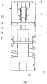
Fig. 1 is a schematic perspective assembling view of a locking and unlocking fixture capable of adaptive position adjustment of the invention; -
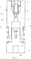
Fig. 2 is a first cross-sectional view of the locking and unlocking fixture capable of adaptive position adjustment of the invention in an assembled state; -
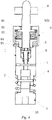
Fig. 3 is a second cross-sectional view of the locking and unlocking fixture capable of adaptive position adjustment of the invention in the assembled state; -
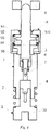
Fig. 4 is a schematic matching view when the locking and unlocking fixture capable of adaptive position adjustment of the invention unlocks a locking device of a power battery; -
Fig. 5 is a schematic view before the locking and unlocking fixture capable of adaptive position adjustment of the invention locks the locking device of the power battery; and -
Fig. 6 is a schematic view during a process in which the locking and unlocking fixture capable of adaptive position adjustment of the invention locks the locking device of the power battery. - 1. Fixture sleeve; 11. First radial hole; 12. Second radial hole; 13. Connecting structure; 14. Square hole; 15. Circular hole; 2. First spring; 3. Base; 31. Cylindrical segment; 32. Square columnar segment; 321. First strip-shaped hole; 33. Connecting hole; 4. First connecting rod; 5. Push rod; 51. Second strip-shaped hole; 6. Second spring; 7. Second connecting rod; 8. Locking plate; 9. Locking device; 91. Bushing; 92. Third spring; 93. Threaded rod; 931. Flange; 94. Nut; 95. Retaining ring.
- Preferred embodiments of the invention are described below with reference to the accompanying drawings. It should be understood by those skilled in the art that these embodiments are only for explaining the technical principles of the invention and are not intended to limit the scope of protection of the invention. For example, although various components in the drawings are drawn in a certain proportional relationship, such a proportional relationship is not fixed, those skilled in the art can make amendments according to requirements so as to adapt to specific application scenarios.
- It should be noted that in the description of the invention, the terms, such as "center", "upper", "lower", "left", "right", "vertical", "horizontal", "inner" and "outer", that indicate directions or positional relationships are based on the directions or positional relationships shown in the drawings only for convenience of description, and do not indicate or imply that the device or element must have a specific orientation, be constructed and operate in a specific orientation, and therefore cannot be understood as limitation to the invention. In addition, the terms "first", "second" and "third" are for descriptive purposes only and should not be construed as indicating or implying relative importance.
- In addition, it should also be noted that in the description of the invention, the terms "install", "couple" and "connect" are to be understood in a broad sense, for example, it may be a fixed connection, a detachable connection, or an integral connection; a mechanical connection or an electrical connection; a direct connection or an indirect connection via an intermediate medium, or a communication between the interiors of two elements, unless expressly specified and defined otherwise. For those skilled in the art, the specific meaning of the above terms in the invention can be interpreted according to the specific situation.
- The locking and unlocking fixture capable of adaptive position adjustment of the invention is mainly used for locking and unlocking a chassis-type power battery installed on a chassis of the electric vehicle or a battery swap station for the electric vehicle, in particular, for unlocking a power battery which has been fixedly installed, and the locking and unlocking fixture of the invention has significant advantages over the existing locking and unlocking devices. The details are as follows:
- As shown in
Fig. 1 , the locking and unlocking fixture capable of adaptive position adjustment of the invention mainly comprises afixture sleeve 1, afirst spring 2, abase 3 and a spring pusher. Thefixture sleeve 1 is provided with a firstradial hole 11, a secondradial hole 12 and a connectingstructure 13. Thebase 3 comprises a first columnar segment and a second columnar segment, for example, the first columnar segment may be a lowercylindrical segment 31 inFig. 1 , and the second columnar segment may be an upper prismatic segment inFig. 1 (taking a square columnar (quadrangular prismatic)segment 32 as an example). The squarecolumnar segment 32 is provided with a first strip-shapedhole 321, through which first strip-shapedhole 321 the first connectingrod 4 installed therein can be moved up and down relative to thebase 3 in the length direction of the hole. The spring pusher mainly comprises apush rod 5, asecond spring 6 and a second connectingrod 7. Thepush rod 5 is provided with a second strip-shapedhole 51, through which second strip-shapedhole 51 the second connectingrod 7 installed therein can be moved up and down relative to thepush rod 5 in the length direction of the hole. Further, thesecond spring 6 is provided between thepush rod 5 and the second connectingrod 7, and the second connectingrod 7 is pushed by thesecond spring 6 to the lowermost end of the second strip-shapedhole 51 in a normal state. - As shown in
Figs. 2 and3 , the first connectingrod 4 is also installed into the firstradial hole 11, and when thefixture sleeve 1 and thebase 3 are connected via the first connectingrod 4, thefixture sleeve 1 can slide up and down relative to thebase 3 as the first slidingrod 4 slides in the hole length direction of the first strip-shapedhole 321, the size of the opening of the first strip-shapedhole 321 in the vertical direction can limit the length of the relative sliding distance between thefixture sleeve 1 and thebase 3, so that the firstradial hole 11, the first strip-shapedhole 321 and the first connectingrod 4 together constitute the first limiting mechanism described in the claims. Thefixture sleeve 1 and thebase 3 preferably form a clearance fit in the radial direction, in particular, the squarecolumnar segment 32 is sheathed inside the first sliding segment (asquare hole 14 shown inFigs. 2 and3 ) on thefixture sleeve 1, and a clearance fit is formed between the two such that thefixture sleeve 1 can float relative to thebase 3 within a set range (mainly the floating of thefixture sleeve 1 relative to thebase 3 in the horizontal direction), the size of the floating range being mainly determined by the size of the clearance. It will be understood by those skilled in the art that the cross section of the prismatic segment is not strictly polygonal, and may be any other form of non-cylindrical segment other than the prismatic structure in a geometric sense, for example, a D-shaped columnar segment, an elliptical columnar segment, a spline shaft-type columnar segment, etc. It should be noted that, as the shape of the second columnar segment changes, thesquare hole 14 for accommodating the second columnar segment also needs to be changed correspondingly, so that thebase 1 can drive thefixture sleeve 1 to rotate in the assembled state. Further, thefirst spring 2 is provided between thefixture sleeve 1 and thebase 3 in the axial direction of thefixture sleeve 1, the upper end of thefirst spring 2 abuts against a shoulder (not shown) provided on thefixture sleeve 1, and the lower end of thefirst spring 2 abuts against an upper surface of thecylindrical segment 31, such that thefixture sleeve 1 can return to its initial position, namely the position in which thefixture sleeve 1 is coaxial or approximately coaxial with thecylindrical segment 31, relative to thebase 3 when no external force is applied. - With continued reference to
Figs. 2 and3 , the spring pusher is installed inside a second sliding segment (shown as acircular hole 15 inFigs. 2 and3 ) on thefixture sleeve 1, specifically, the second connectingrod 7 is also installed inside the secondradial hole 12, and when thefixture sleeve 1 and the spring pusher are connected via the second connectingrod 7, thefixture sleeve 1 can slide up and down relative to thepush rod 5 as the second connectingrod 7 slides in the hole length direction of the second strip-shapedhole 51. The size of the opening of the second strip-shapedhole 51 in the vertical direction can limit the length of the relative sliding distance between thefixture sleeve 1 and thepush rod 5, so that the secondradial hole 12, the second strip-shapedhole 51 and the second connectingrod 7 together form the second limiting mechanism described in the claims. - As shown in
Fig. 4 , it shows the connection state when the locking and unlocking fixture of the invention unlocks thelocking device 9 of the power battery. It should be noted that thelocking device 9 mainly comprises: abushing 91; athird spring 92, a threadedrod 93, and anut 94, which are provided inside the bushing; and a retainingring 95 provided at the bottom end of thebushing 91. Thebushing 91 is fixedly connected to the power battery, the threadedrod 93 passes through thebushing 91 in the axial direction, thethird spring 92 and thenut 94 are both sheathed over the threadedrod 93, and thenut 94 abuts against the upper end of the retainingring 95 under the action of thethird spring 92. - Further, an upper segment of the threaded
rod 93 is provided with a thread so that the threadedrod 93 can be connected, via the thread, to alocking plate 8 provided on the electric vehicle or a battery swap station for the electric vehicle; and a lower segment of the threadedrod 93 is provided with an external spline, and thenut 94 engaged with the lower segment of the threadedrod 93 is provided with a spline hole so that the threadedrod 93 and thenut 94 can be engaged via the spline. Still further, the spline engagement between the threadedrod 93 and thenut 94 uses a clearance fit so that thenut 94 can freely slide in the axial direction of the threadedrod 93. It will be understood by those skilled in the art that the length, width and height of the external spline on the threadedrod 93 can be set according to requirements, such as 9-teeth spline, 11-teeth spline and 13-teeth spline, etc. Alternatively, those skilled in the art can also connect the threadedrod 93 and thenut 94 by means of a connection other than the spline, as long as thenut 94 can drive the threadedrod 93 to rotate, and thenut 94 can freely slide in the axial direction of the threadedrod 93. - Yet still further, an outer surface of the
nut 94 is provided with a connected structure (not shown) that matches the connectingstructure 13 on thefixture sleeve 1. Specifically, the connected structure is a groove, and the connectingstructure 13 is a raised structure. Alternatively, those skilled in the art can also make appropriate adjustments according to requirements to enable thenut 94 and thefixture sleeve 1 to be connected by matching the connectingstructure 13 with the connected structure. It will be understood by those skilled in the art that thenut 94 and thefixture sleeve 1 form a clearance fit in the radial direction so that thenut 94 and thefixture sleeve 1 can be smoothly connected and disconnected. - It will be understood by those skilled in the art that the locking and unlocking fixture of the invention is installed to a battery swap trolley (or a battery swap apparatus such as a battery swap robot) for the power battery to realize locking and unlocking actions on the power battery. Further, in the specific implementation, it is necessary to provide a locking and unlocking fixture, which corresponds to the
locking device 9 of the power battery, on the battery swap trolley. - The working principle of the locking and unlocking fixture of the invention will be briefly described below with reference to
Fig. 4 . - When the power battery is removed from the electric vehicle or the battery swap station, first, the battery swap trolley will drive to the battery swap position below the power battery. Then, all the locking and unlocking fixtures on the battery swap trolley are lifted at the same time until the connecting
structure 13 of thefixture sleeve 1 is sheathed into thenut 94. Finally, the driving device (for example, a servo motor), which is connected to the connectinghole 33 of thebase 3, drives thebase 3 to rotate, which in turn drives thefixture sleeve 1 to rotate by means of the cooperation between thesquare hole 14 and the squarecolumnar segment 32, and thenut 94 is further driven to turn the threadedrod 93 until the threadedrod 93 disengages from the lockingplate 8. - When the power battery is installed to the electric vehicle or the battery swap station, first, the battery swap trolley will drive to the battery swap position below the power battery. Then, all the locking and unlocking fixtures on the battery swap trolley and the power battery are lifted at the same time until the connecting
structure 13 of thefixture sleeve 1 is sheathed into thenut 94. Finally, the driving device, which is connected to the connectinghole 33 of thebase 3, drives thebase 3 to rotate, which in turn drives thefixture sleeve 1 to rotate by means of the first connectingrod 4, thenut 94 is further driven to turn the threadedrod 93 until the threadedrod 93 and thelocking plate 8 are tightened to a pre-set torque, and the driving device stops rotating. - As shown in
Fig. 5 , when the power battery is not installed to the electric vehicle or the battery swap station, the threadedrod 93 is lowered by its own gravity until theflange 931 thereon abuts against thenut 94, so that the lower end of the threadedrod 93 will extend by a distance beyond the lower end of thenut 94, and the connectingstructure 13 in thefixture sleeve 1 thus cannot match and be connected to thenut 94. - As shown in
Fig. 6 , when the power battery is locked by the locking and unlocking fixture, the threadedrod 93 is pushed upwardly by the spring pusher, so that the connectingstructure 13 in thefixture sleeve 1 can come into contact with thenut 94. Specifically, thesecond spring 7 in the spring pusher pushes thepush rod 5 upward and further pushes the threadedrod 93 upward such that the connectingstructure 13 in thefixture sleeve 1 is successfully connected to thenut 94. In a preferred embodiment of the invention, compared with thepush rod 5 directly pushing the threadedrod 93, thepush rod 5 pushing the threadedrod 93 by means of the spring force of thesecond spring 7 can effectively reduce the impact occurring when the threadedrod 93 comes into contact with the lockingplate 8. - It will also be understood by those skilled in the art that in the preferred embodiments of the invention, due to the radial clearance fit between the
fixture sleeve 1 and thebase 3, when the battery swap trolley swaps the power battery, thefixture sleeve 1 and thenut 94 can also be connected and engaged even if a small amount of positional error occurs therebetween, thereby effectively reducing the requirements for the machining and installation precision of the locking and unlocking device for the power battery. Those skilled in the art can make equivalent changes or substitutions to the related technical features without departing from the appended claims.
Claims (5)
- A locking and unlocking fixture capable of adaptive position adjustment for locking and unlocking a power battery installed to an electric vehicle, the locking and unlocking fixture comprises:a fixture sleeve (1); anda base (3), which is received in the fixture sleeve (1) and is further connected to a driving device, whereinthe fixture sleeve (1) is floatable within a set range relative to the base (3) during a process in which the driving device drives the base (3) to approach the power battery;wherein the base (3) comprises a first columnar segment (31) and a second columnar segment (32), wherein the second columnar segment (32) is a prismatic segment, which is received in a first sliding segment (14) of the fixture sleeve (1) in a clearance fit manner;wherein a first spring (2) is sheathed over the fixture sleeve (1) corresponding to the first sliding segment (14), the first spring (2) is further connected to the first columnar segment (31), and in the case where an external force is removed, the first spring (2) enables the fixture sleeve (1) to return to an initial position of the fixture sleeve (1) relative to the base (3);a first limiting mechanism, which enables the fixture sleeve (1) to float in a vertical direction relative to the base (3) as the driving device moves the base (3) in the vertical direction;a second limiting mechanism received in a second sliding segment (15) of the fixture sleeve (1), wherein the second limiting mechanism is capable of jacking up a threaded rod (93) of a locking device (9) of the power battery corresponding to the locking and unlocking fixture during a process in which the base (3) moves in the vertical direction;characterized in thatthe second limiting mechanism comprises:a push rod (5), which is received in the second sliding segment (15), and is slidable in an axial direction of the fixture sleeve (1);a second strip-shaped hole (51) provided in the push rod (5);a second radial hole (12) provided in the second sliding segment (15); anda second connecting rod (7) connected to the second strip-shaped hole (51) and the second radial hole (12), respectively, wherein the second connecting rod (7) is slidable within a hole length range of the second strip-shaped hole (51), such that the fixture sleeve (1) is floatable relative to the push rod (5) within the hole length range of the second strip-shaped hole (51).
- The locking and unlocking fixture capable of adaptive position adjustment according to claim 1, wherein the first limiting mechanism comprises:a first strip-shaped hole (321) provided in the prismatic segment;a first radial hole (11) provided in the first sliding segment (14); anda first connecting rod (4) connected to the first strip-shaped hole (321) and the first radial hole (11), respectively, wherein the first connecting rod (4) is slidable within a hole length range of the first strip-shaped hole (321), such that the fixture sleeve (1) is floatable relative to the base (3) within the hole length range of the first strip-shaped hole (321).
- The locking and unlocking fixture capable of adaptive position adjustment according to claim 1, wherein the top of the fixture sleeve (1) is provided with a connecting structure which is able to match and be butt against the threaded rod (93) of the locking device (9) of the power battery.
- The locking and unlocking fixture capable of adaptive position adjustment according to claim 1, wherein a second spring (6) is sheathed over the push rod (5), and in the case where an external force is removed, the second spring (6) enables the push rod (5) to return to an initial position relative to the fixture sleeve (1).
- The locking and unlocking fixture capable of adaptive position adjustment according to claim 4, wherein the second spring (6) is axially provided between the push rod (5) and the second connecting rod (7), and
in the case where an external force is removed, the second connecting rod (7) is able to abut against the end of the second strip-shaped hole (51) that is close to the base (3).
Applications Claiming Priority (2)
| Application Number | Priority Date | Filing Date | Title |
|---|---|---|---|
| CN201720006535.9U CN206351680U (en) | 2017-01-04 | 2017-01-04 | Self-adapting adjusted positions plus Unlocking clamp |
| PCT/CN2018/071396 WO2018127098A1 (en) | 2017-01-04 | 2018-01-04 | Locking and unlocking fixture capable of adaptive position adjustment |
Publications (3)
| Publication Number | Publication Date |
|---|---|
| EP3566915A1 EP3566915A1 (en) | 2019-11-13 |
| EP3566915A4 EP3566915A4 (en) | 2020-06-24 |
| EP3566915B1 true EP3566915B1 (en) | 2022-08-03 |
Family
ID=59349146
Family Applications (1)
| Application Number | Title | Priority Date | Filing Date |
|---|---|---|---|
| EP18736749.5A Active EP3566915B1 (en) | 2017-01-04 | 2018-01-04 | Locking and unlocking fixture capable of adaptive position adjustment |
Country Status (5)
| Country | Link |
|---|---|
| US (1) | US11518226B2 (en) |
| EP (1) | EP3566915B1 (en) |
| CN (1) | CN206351680U (en) |
| TW (1) | TWM568290U (en) |
| WO (1) | WO2018127098A1 (en) |
Families Citing this family (43)
| Publication number | Priority date | Publication date | Assignee | Title |
|---|---|---|---|---|
| CN206351680U (en) * | 2017-01-04 | 2017-07-25 | 上海蔚来汽车有限公司 | Self-adapting adjusted positions plus Unlocking clamp |
| US11603210B2 (en) | 2017-04-27 | 2023-03-14 | Flyon Aerosystems Ltd. | High traffic-rate aerial transportation system with low-footprint Vertiport |
| CN107775324B (en) * | 2017-10-26 | 2021-06-11 | 蔚来(安徽)控股有限公司 | Bolt locking method, bolt unlocking method, bolt locking and unlocking method and vehicle battery replacement method |
| CN109987066B (en) * | 2017-12-29 | 2022-06-03 | 上海电巴新能源科技有限公司 | Battery box unlocking device, battery box and battery box quick battery changing system |
| CN108608851B (en) * | 2018-06-06 | 2024-07-23 | 博众精工科技股份有限公司 | Automobile battery locking mechanism |
| CN114834299B (en) * | 2018-09-10 | 2025-01-24 | 奥动新能源汽车科技有限公司 | Battery box unlocking control system and control method |
| CN110001598B (en) * | 2018-12-03 | 2023-05-23 | 蔚来(安徽)控股有限公司 | Locking and unlocking assembly, power conversion platform and power conversion station |
| CN110034343B (en) * | 2019-05-21 | 2024-07-30 | 博众精工科技股份有限公司 | Press mounting device and press mounting system |
| CN110379966A (en) * | 2019-06-27 | 2019-10-25 | 博众精工科技股份有限公司 | Locking system for battery component |
| CN110920373B (en) * | 2019-12-25 | 2024-04-09 | 上海玖行能源科技有限公司 | A three-stage positioning and locking device and method for a battery box for electric heavy trucks |
| CN114801861A (en) | 2020-01-02 | 2022-07-29 | 奥动新能源汽车科技有限公司 | Visual positioning method and system for battery swapping equipment |
| CN111121790A (en) * | 2020-01-08 | 2020-05-08 | 湖北乐程汽车服务有限公司 | A remotely operable rental vehicle positioning system |
| CN113895287B (en) * | 2020-07-06 | 2024-08-06 | 奥动新能源汽车科技有限公司 | Unlocking device and battery replacement device including the same |
| CN111845312A (en) * | 2020-08-19 | 2020-10-30 | 幻电科技发展有限公司 | A new type of locking mechanism for quick-change battery packs for electric vehicles |
| CN111942214B (en) * | 2020-08-25 | 2022-02-01 | 重庆峘能电动车科技有限公司 | Locking mechanism, automobile chassis and new energy automobile |
| CN112389179B (en) * | 2020-10-10 | 2022-04-26 | 东风汽车集团有限公司 | A vehicle battery pack unlocking device and assembly |
| CN112271399B (en) * | 2020-11-09 | 2023-05-05 | 河南普航电子设备有限公司 | But quick replacement's lithium cell grafting positioner |
| CN114523833B (en) * | 2020-11-23 | 2024-04-02 | 上海汽车集团股份有限公司 | Car battery frame fixing device and car |
| CN112498080A (en) * | 2020-12-05 | 2021-03-16 | 上海弗则新能源科技有限公司 | Quick locking mechanism and battery installation package with same |
| CN113085651B (en) * | 2021-04-23 | 2024-11-22 | 上海伊控动力系统有限公司 | A quick-change locking module for a quick-change power battery |
| CN113211379B (en) * | 2021-05-12 | 2023-09-29 | 昆山斯沃普智能装备有限公司 | Vehicle locking and unlocking mechanism with bolt protection function |
| CN113246710B (en) * | 2021-06-10 | 2022-08-26 | 东风柳州汽车有限公司 | Power battery's mounting structure and car |
| CN113183741B (en) * | 2021-06-18 | 2025-06-17 | 长城汽车股份有限公司 | Locking device, battery pack assembly and vehicle |
| CN113320373B (en) * | 2021-06-30 | 2022-07-22 | 东风柳州汽车有限公司 | Fixing assembly, battery pack assembly and vehicle |
| CN113613424B (en) * | 2021-07-14 | 2023-06-09 | 利亚德光电股份有限公司 | Adjusting mechanism of box and LED box assembly |
| CN113682190B (en) * | 2021-07-26 | 2022-06-07 | 安徽国防科技职业学院 | Automatic battery replacement system of new energy automobile |
| CN113859394A (en) * | 2021-11-09 | 2021-12-31 | 奇瑞汽车股份有限公司 | Tool for reversely arranging automobile engine cover and installation method of automobile engine cover |
| CN115284950B (en) * | 2021-11-30 | 2024-10-18 | 奥动新能源汽车科技有限公司 | Battery swap tray for electric vehicle and electric vehicle |
| CN119734664B (en) * | 2021-12-02 | 2025-11-21 | 奥动新能源股份有限公司 | Battery replacement equipment and battery replacement robot comprising same |
| CN119749479A (en) * | 2021-12-02 | 2025-04-04 | 奥动新能源汽车科技有限公司 | Pallet mounting mechanism, battery replacement equipment and battery replacement station |
| CN115431734B (en) * | 2021-12-26 | 2026-04-03 | 奥动新能源股份有限公司 | Vehicle body brackets for mounting battery packs and electric vehicles |
| CN114364201B (en) * | 2022-01-11 | 2024-01-30 | 中国测试技术研究院 | Sensor for metering detection |
| CN114454771A (en) * | 2022-01-28 | 2022-05-10 | 博众精工科技股份有限公司 | A floating battery unlocking structure and unlocking gun |
| CN114312277B (en) * | 2022-01-28 | 2026-03-10 | 北京胜能能源科技有限公司 | Locking mechanism and electric automobile |
| CN114290283B (en) * | 2022-02-09 | 2023-09-22 | 博众精工科技股份有限公司 | Mounting structure of elastic workpiece |
| CN114701345B (en) * | 2022-03-28 | 2025-07-04 | 上海优续新能源科技有限公司 | Battery box locking mechanism for electric vehicles |
| CN114734401B (en) * | 2022-03-30 | 2024-04-16 | 山东汉普机械工业有限公司 | Bidirectional self-tightening hexagonal sleeve |
| CN115450993B (en) * | 2022-04-02 | 2026-03-13 | 奥动新能源股份有限公司 | Unlock Components |
| CN114714273B (en) * | 2022-04-19 | 2024-03-19 | 深圳市华乐珠宝首饰有限公司 | Multifunctional jewelry positioning fixture |
| CN115000613B (en) * | 2022-06-10 | 2023-09-22 | 中国第一汽车股份有限公司 | Nut type quick-mounting device and method for power battery |
| CN115395171B (en) * | 2022-08-01 | 2023-06-27 | 东风汽车集团股份有限公司 | Battery fixing and locking device and vehicle |
| CN116533733A (en) * | 2022-12-30 | 2023-08-04 | 奥动新能源汽车科技有限公司 | Unlocking mechanisms, battery packs and electric vehicles |
| CN220956387U (en) * | 2024-02-26 | 2024-05-14 | 宁德时代新能源科技股份有限公司 | Mounting device, battery suite and electric automobile |
Family Cites Families (19)
| Publication number | Priority date | Publication date | Assignee | Title |
|---|---|---|---|---|
| SE316967B (en) * | 1967-09-15 | 1969-11-03 | E Jahrl | |
| US4535863A (en) * | 1983-08-26 | 1985-08-20 | Becker John R | Battery security and hold-down device |
| US4637234A (en) * | 1984-08-13 | 1987-01-20 | Oy Wartsila Ab | Cartridge lock |
| ITCZ20020006U1 (en) * | 2002-07-30 | 2002-10-28 | Fioravante Rotundo | ADJUSTABLE STOCK |
| US7468418B2 (en) * | 2003-04-29 | 2008-12-23 | Avi Biopharma., Inc. | Compositions for enhancing transport of molecules into cells |
| US6997724B2 (en) * | 2004-06-28 | 2006-02-14 | Earl Ronald J | Aircraft battery lockout device |
| US7782626B2 (en) * | 2007-02-02 | 2010-08-24 | Black & Decker Inc. | Portable power driven system with battery anti-theft apparatus |
| JP2010188472A (en) * | 2009-02-18 | 2010-09-02 | Nissan Motor Co Ltd | Socket for rotary tool and battery changer using the same |
| JP2010203574A (en) * | 2009-03-05 | 2010-09-16 | Nissan Motor Co Ltd | Screw type lock mechanism |
| US20120210757A1 (en) * | 2011-02-21 | 2012-08-23 | Gentile Frank L | Magnetic Lock Assembly |
| CN202743032U (en) * | 2012-08-10 | 2013-02-20 | 王俊 | Battery locking mechanism |
| CN102815190B (en) * | 2012-08-10 | 2015-02-11 | 王俊 | Battery locking mechanism |
| CN203543623U (en) * | 2013-10-31 | 2014-04-16 | 深圳精智机器有限公司 | Battery locking mechanism |
| CN104724080B (en) * | 2013-12-20 | 2017-04-12 | 国家电网公司 | Unlocking device |
| CN205601588U (en) * | 2016-03-03 | 2016-09-28 | 上海电巴新能源科技有限公司 | Big bus battery package release mechanism |
| CN106080159B (en) * | 2016-05-25 | 2019-03-22 | 上海蔚来汽车有限公司 | Lock body component, power battery, its lockable mechanism and application method, the vehicles |
| CN105946812B (en) * | 2016-06-23 | 2017-12-19 | 蔚来汽车有限公司 | Lock body assembly, power battery, locking mechanism of power battery, use method of locking mechanism and vehicle |
| CN106979192B (en) * | 2016-12-12 | 2019-03-26 | 上海蔚来汽车有限公司 | Circumferential lockable mechanism, battery locking device, power battery pack and vehicle |
| CN206351680U (en) * | 2017-01-04 | 2017-07-25 | 上海蔚来汽车有限公司 | Self-adapting adjusted positions plus Unlocking clamp |
-
2017
- 2017-01-04 CN CN201720006535.9U patent/CN206351680U/en active Active
-
2018
- 2018-01-04 US US16/475,889 patent/US11518226B2/en active Active
- 2018-01-04 TW TW107200166U patent/TWM568290U/en unknown
- 2018-01-04 WO PCT/CN2018/071396 patent/WO2018127098A1/en not_active Ceased
- 2018-01-04 EP EP18736749.5A patent/EP3566915B1/en active Active
Also Published As
| Publication number | Publication date |
|---|---|
| US11518226B2 (en) | 2022-12-06 |
| EP3566915A1 (en) | 2019-11-13 |
| US20190344651A1 (en) | 2019-11-14 |
| WO2018127098A1 (en) | 2018-07-12 |
| TWM568290U (en) | 2018-10-11 |
| CN206351680U (en) | 2017-07-25 |
| EP3566915A4 (en) | 2020-06-24 |
Similar Documents
| Publication | Publication Date | Title |
|---|---|---|
| EP3566915B1 (en) | Locking and unlocking fixture capable of adaptive position adjustment | |
| CN106627083B (en) | Quick locking and unlocking kit | |
| EP3336929B1 (en) | Battery locking device, new energy source transportation tool, and method for assembling and disassembling power battery | |
| EP3476634B1 (en) | Lock body assembly for a battery lock-up mechanism | |
| CN115303045A (en) | Battery pack for electric automobile and electric automobile | |
| CN217477133U (en) | Battery package trades electricity and moves subassembly, trades electric shuttle | |
| CN103600644A (en) | Battery locking mechanism | |
| CN113415207A (en) | Hydraulic locking mechanism of battery replacement system of pure electric heavy truck | |
| CN212148389U (en) | Locking bolt and battery locking means | |
| CN104724080B (en) | Unlocking device | |
| EP3725607A1 (en) | Positioning mechanism and battery-replacing robot having same | |
| CN114987278B (en) | A battery quick-change device and method capable of being controlled by a vehicle | |
| CN110758144B (en) | Retaining assembly for a vehicle wireless charging station | |
| CN215244439U (en) | Hydraulic locking mechanism of battery replacement system of pure electric heavy truck | |
| CN213705229U (en) | Lock mechanism | |
| CN219564836U (en) | Locking mechanism, new energy automobile and power conversion system | |
| CN220009435U (en) | Trade electric locking mechanism and electric vehicle | |
| CN114261309B (en) | Electric heavy-duty truck lateral power swapping system and electric heavy-duty truck | |
| CN113370839B (en) | Automatic electric energy supply device for new energy automobile based on Internet of vehicles technology | |
| CN215886038U (en) | Hoisting tool | |
| CN209795152U (en) | Transmission mechanism for locking device and locking device with transmission mechanism | |
| CN110341449B (en) | A locking structure between a battery box and a car compartment | |
| CN219172221U (en) | Battery unlocking device and battery replacement platform | |
| CN211075500U (en) | Power battery system and power battery power conversion system | |
| CN221305674U (en) | Locking device of motor |
Legal Events
| Date | Code | Title | Description |
|---|---|---|---|
| STAA | Information on the status of an ep patent application or granted ep patent |
Free format text: STATUS: THE INTERNATIONAL PUBLICATION HAS BEEN MADE |
|
| PUAI | Public reference made under article 153(3) epc to a published international application that has entered the european phase |
Free format text: ORIGINAL CODE: 0009012 |
|
| STAA | Information on the status of an ep patent application or granted ep patent |
Free format text: STATUS: REQUEST FOR EXAMINATION WAS MADE |
|
| 17P | Request for examination filed |
Effective date: 20190731 |
|
| AK | Designated contracting states |
Kind code of ref document: A1 Designated state(s): AL AT BE BG CH CY CZ DE DK EE ES FI FR GB GR HR HU IE IS IT LI LT LU LV MC MK MT NL NO PL PT RO RS SE SI SK SM TR |
|
| AX | Request for extension of the european patent |
Extension state: BA ME |
|
| DAV | Request for validation of the european patent (deleted) | ||
| DAX | Request for extension of the european patent (deleted) | ||
| A4 | Supplementary search report drawn up and despatched |
Effective date: 20200528 |
|
| RIC1 | Information provided on ipc code assigned before grant |
Ipc: B60S 5/06 20190101AFI20200520BHEP Ipc: B60K 1/04 20190101ALI20200520BHEP |
|
| STAA | Information on the status of an ep patent application or granted ep patent |
Free format text: STATUS: EXAMINATION IS IN PROGRESS |
|
| 17Q | First examination report despatched |
Effective date: 20210909 |
|
| GRAP | Despatch of communication of intention to grant a patent |
Free format text: ORIGINAL CODE: EPIDOSNIGR1 |
|
| STAA | Information on the status of an ep patent application or granted ep patent |
Free format text: STATUS: GRANT OF PATENT IS INTENDED |
|
| INTG | Intention to grant announced |
Effective date: 20220314 |
|
| GRAS | Grant fee paid |
Free format text: ORIGINAL CODE: EPIDOSNIGR3 |
|
| GRAA | (expected) grant |
Free format text: ORIGINAL CODE: 0009210 |
|
| STAA | Information on the status of an ep patent application or granted ep patent |
Free format text: STATUS: THE PATENT HAS BEEN GRANTED |
|
| AK | Designated contracting states |
Kind code of ref document: B1 Designated state(s): AL AT BE BG CH CY CZ DE DK EE ES FI FR GB GR HR HU IE IS IT LI LT LU LV MC MK MT NL NO PL PT RO RS SE SI SK SM TR |
|
| REG | Reference to a national code |
Ref country code: AT Ref legal event code: REF Ref document number: 1508508 Country of ref document: AT Kind code of ref document: T Effective date: 20220815 Ref country code: CH Ref legal event code: EP |
|
| REG | Reference to a national code |
Ref country code: DE Ref legal event code: R096 Ref document number: 602018038774 Country of ref document: DE |
|
| REG | Reference to a national code |
Ref country code: IE Ref legal event code: FG4D |
|
| REG | Reference to a national code |
Ref country code: LT Ref legal event code: MG9D |
|
| REG | Reference to a national code |
Ref country code: NL Ref legal event code: MP Effective date: 20220803 |
|
| PG25 | Lapsed in a contracting state [announced via postgrant information from national office to epo] |
Ref country code: SE Free format text: LAPSE BECAUSE OF FAILURE TO SUBMIT A TRANSLATION OF THE DESCRIPTION OR TO PAY THE FEE WITHIN THE PRESCRIBED TIME-LIMIT Effective date: 20220803 Ref country code: RS Free format text: LAPSE BECAUSE OF FAILURE TO SUBMIT A TRANSLATION OF THE DESCRIPTION OR TO PAY THE FEE WITHIN THE PRESCRIBED TIME-LIMIT Effective date: 20220803 Ref country code: PT Free format text: LAPSE BECAUSE OF FAILURE TO SUBMIT A TRANSLATION OF THE DESCRIPTION OR TO PAY THE FEE WITHIN THE PRESCRIBED TIME-LIMIT Effective date: 20221205 Ref country code: NO Free format text: LAPSE BECAUSE OF FAILURE TO SUBMIT A TRANSLATION OF THE DESCRIPTION OR TO PAY THE FEE WITHIN THE PRESCRIBED TIME-LIMIT Effective date: 20221103 Ref country code: NL Free format text: LAPSE BECAUSE OF FAILURE TO SUBMIT A TRANSLATION OF THE DESCRIPTION OR TO PAY THE FEE WITHIN THE PRESCRIBED TIME-LIMIT Effective date: 20220803 Ref country code: LV Free format text: LAPSE BECAUSE OF FAILURE TO SUBMIT A TRANSLATION OF THE DESCRIPTION OR TO PAY THE FEE WITHIN THE PRESCRIBED TIME-LIMIT Effective date: 20220803 Ref country code: LT Free format text: LAPSE BECAUSE OF FAILURE TO SUBMIT A TRANSLATION OF THE DESCRIPTION OR TO PAY THE FEE WITHIN THE PRESCRIBED TIME-LIMIT Effective date: 20220803 Ref country code: FI Free format text: LAPSE BECAUSE OF FAILURE TO SUBMIT A TRANSLATION OF THE DESCRIPTION OR TO PAY THE FEE WITHIN THE PRESCRIBED TIME-LIMIT Effective date: 20220803 Ref country code: ES Free format text: LAPSE BECAUSE OF FAILURE TO SUBMIT A TRANSLATION OF THE DESCRIPTION OR TO PAY THE FEE WITHIN THE PRESCRIBED TIME-LIMIT Effective date: 20220803 |
|
| REG | Reference to a national code |
Ref country code: AT Ref legal event code: MK05 Ref document number: 1508508 Country of ref document: AT Kind code of ref document: T Effective date: 20220803 |
|
| PG25 | Lapsed in a contracting state [announced via postgrant information from national office to epo] |
Ref country code: PL Free format text: LAPSE BECAUSE OF FAILURE TO SUBMIT A TRANSLATION OF THE DESCRIPTION OR TO PAY THE FEE WITHIN THE PRESCRIBED TIME-LIMIT Effective date: 20220803 Ref country code: IS Free format text: LAPSE BECAUSE OF FAILURE TO SUBMIT A TRANSLATION OF THE DESCRIPTION OR TO PAY THE FEE WITHIN THE PRESCRIBED TIME-LIMIT Effective date: 20221203 Ref country code: HR Free format text: LAPSE BECAUSE OF FAILURE TO SUBMIT A TRANSLATION OF THE DESCRIPTION OR TO PAY THE FEE WITHIN THE PRESCRIBED TIME-LIMIT Effective date: 20220803 Ref country code: GR Free format text: LAPSE BECAUSE OF FAILURE TO SUBMIT A TRANSLATION OF THE DESCRIPTION OR TO PAY THE FEE WITHIN THE PRESCRIBED TIME-LIMIT Effective date: 20221104 |
|
| PG25 | Lapsed in a contracting state [announced via postgrant information from national office to epo] |
Ref country code: SM Free format text: LAPSE BECAUSE OF FAILURE TO SUBMIT A TRANSLATION OF THE DESCRIPTION OR TO PAY THE FEE WITHIN THE PRESCRIBED TIME-LIMIT Effective date: 20220803 Ref country code: RO Free format text: LAPSE BECAUSE OF FAILURE TO SUBMIT A TRANSLATION OF THE DESCRIPTION OR TO PAY THE FEE WITHIN THE PRESCRIBED TIME-LIMIT Effective date: 20220803 Ref country code: DK Free format text: LAPSE BECAUSE OF FAILURE TO SUBMIT A TRANSLATION OF THE DESCRIPTION OR TO PAY THE FEE WITHIN THE PRESCRIBED TIME-LIMIT Effective date: 20220803 Ref country code: CZ Free format text: LAPSE BECAUSE OF FAILURE TO SUBMIT A TRANSLATION OF THE DESCRIPTION OR TO PAY THE FEE WITHIN THE PRESCRIBED TIME-LIMIT Effective date: 20220803 Ref country code: AT Free format text: LAPSE BECAUSE OF FAILURE TO SUBMIT A TRANSLATION OF THE DESCRIPTION OR TO PAY THE FEE WITHIN THE PRESCRIBED TIME-LIMIT Effective date: 20220803 |
|
| REG | Reference to a national code |
Ref country code: DE Ref legal event code: R097 Ref document number: 602018038774 Country of ref document: DE |
|
| PG25 | Lapsed in a contracting state [announced via postgrant information from national office to epo] |
Ref country code: SK Free format text: LAPSE BECAUSE OF FAILURE TO SUBMIT A TRANSLATION OF THE DESCRIPTION OR TO PAY THE FEE WITHIN THE PRESCRIBED TIME-LIMIT Effective date: 20220803 Ref country code: EE Free format text: LAPSE BECAUSE OF FAILURE TO SUBMIT A TRANSLATION OF THE DESCRIPTION OR TO PAY THE FEE WITHIN THE PRESCRIBED TIME-LIMIT Effective date: 20220803 |
|
| PLBE | No opposition filed within time limit |
Free format text: ORIGINAL CODE: 0009261 |
|
| STAA | Information on the status of an ep patent application or granted ep patent |
Free format text: STATUS: NO OPPOSITION FILED WITHIN TIME LIMIT |
|
| PG25 | Lapsed in a contracting state [announced via postgrant information from national office to epo] |
Ref country code: AL Free format text: LAPSE BECAUSE OF FAILURE TO SUBMIT A TRANSLATION OF THE DESCRIPTION OR TO PAY THE FEE WITHIN THE PRESCRIBED TIME-LIMIT Effective date: 20220803 |
|
| 26N | No opposition filed |
Effective date: 20230504 |
|
| PG25 | Lapsed in a contracting state [announced via postgrant information from national office to epo] |
Ref country code: SI Free format text: LAPSE BECAUSE OF FAILURE TO SUBMIT A TRANSLATION OF THE DESCRIPTION OR TO PAY THE FEE WITHIN THE PRESCRIBED TIME-LIMIT Effective date: 20220803 |
|
| REG | Reference to a national code |
Ref country code: CH Ref legal event code: PL |
|
| PG25 | Lapsed in a contracting state [announced via postgrant information from national office to epo] |
Ref country code: LU Free format text: LAPSE BECAUSE OF NON-PAYMENT OF DUE FEES Effective date: 20230104 |
|
| REG | Reference to a national code |
Ref country code: BE Ref legal event code: MM Effective date: 20230131 |
|
| PG25 | Lapsed in a contracting state [announced via postgrant information from national office to epo] |
Ref country code: LI Free format text: LAPSE BECAUSE OF NON-PAYMENT OF DUE FEES Effective date: 20230131 Ref country code: CH Free format text: LAPSE BECAUSE OF NON-PAYMENT OF DUE FEES Effective date: 20230131 |
|
| PG25 | Lapsed in a contracting state [announced via postgrant information from national office to epo] |
Ref country code: BE Free format text: LAPSE BECAUSE OF NON-PAYMENT OF DUE FEES Effective date: 20230131 |
|
| PG25 | Lapsed in a contracting state [announced via postgrant information from national office to epo] |
Ref country code: IE Free format text: LAPSE BECAUSE OF NON-PAYMENT OF DUE FEES Effective date: 20230104 |
|
| PG25 | Lapsed in a contracting state [announced via postgrant information from national office to epo] |
Ref country code: IT Free format text: LAPSE BECAUSE OF FAILURE TO SUBMIT A TRANSLATION OF THE DESCRIPTION OR TO PAY THE FEE WITHIN THE PRESCRIBED TIME-LIMIT Effective date: 20220803 |
|
| PG25 | Lapsed in a contracting state [announced via postgrant information from national office to epo] |
Ref country code: MC Free format text: LAPSE BECAUSE OF FAILURE TO SUBMIT A TRANSLATION OF THE DESCRIPTION OR TO PAY THE FEE WITHIN THE PRESCRIBED TIME-LIMIT Effective date: 20220803 |
|
| PG25 | Lapsed in a contracting state [announced via postgrant information from national office to epo] |
Ref country code: MC Free format text: LAPSE BECAUSE OF FAILURE TO SUBMIT A TRANSLATION OF THE DESCRIPTION OR TO PAY THE FEE WITHIN THE PRESCRIBED TIME-LIMIT Effective date: 20220803 |
|
| PG25 | Lapsed in a contracting state [announced via postgrant information from national office to epo] |
Ref country code: BG Free format text: LAPSE BECAUSE OF FAILURE TO SUBMIT A TRANSLATION OF THE DESCRIPTION OR TO PAY THE FEE WITHIN THE PRESCRIBED TIME-LIMIT Effective date: 20220803 |
|
| PG25 | Lapsed in a contracting state [announced via postgrant information from national office to epo] |
Ref country code: BG Free format text: LAPSE BECAUSE OF FAILURE TO SUBMIT A TRANSLATION OF THE DESCRIPTION OR TO PAY THE FEE WITHIN THE PRESCRIBED TIME-LIMIT Effective date: 20220803 |
|
| PG25 | Lapsed in a contracting state [announced via postgrant information from national office to epo] |
Ref country code: CY Free format text: LAPSE BECAUSE OF FAILURE TO SUBMIT A TRANSLATION OF THE DESCRIPTION OR TO PAY THE FEE WITHIN THE PRESCRIBED TIME-LIMIT; INVALID AB INITIO Effective date: 20180104 |
|
| PG25 | Lapsed in a contracting state [announced via postgrant information from national office to epo] |
Ref country code: HU Free format text: LAPSE BECAUSE OF FAILURE TO SUBMIT A TRANSLATION OF THE DESCRIPTION OR TO PAY THE FEE WITHIN THE PRESCRIBED TIME-LIMIT; INVALID AB INITIO Effective date: 20180104 |
|
| PG25 | Lapsed in a contracting state [announced via postgrant information from national office to epo] |
Ref country code: TR Free format text: LAPSE BECAUSE OF FAILURE TO SUBMIT A TRANSLATION OF THE DESCRIPTION OR TO PAY THE FEE WITHIN THE PRESCRIBED TIME-LIMIT Effective date: 20220803 |
|
| PGFP | Annual fee paid to national office [announced via postgrant information from national office to epo] |
Ref country code: GB Payment date: 20260123 Year of fee payment: 9 |
|
| PGFP | Annual fee paid to national office [announced via postgrant information from national office to epo] |
Ref country code: DE Payment date: 20260121 Year of fee payment: 9 |
|
| PGFP | Annual fee paid to national office [announced via postgrant information from national office to epo] |
Ref country code: FR Payment date: 20260123 Year of fee payment: 9 |