EP3566817A1 - Tool bushing, tool bushing arrangement, breaking hammer and mounting method - Google Patents
Tool bushing, tool bushing arrangement, breaking hammer and mounting method Download PDFInfo
- Publication number
- EP3566817A1 EP3566817A1 EP18171764.6A EP18171764A EP3566817A1 EP 3566817 A1 EP3566817 A1 EP 3566817A1 EP 18171764 A EP18171764 A EP 18171764A EP 3566817 A1 EP3566817 A1 EP 3566817A1
- Authority
- EP
- European Patent Office
- Prior art keywords
- bushing
- tool
- tool bushing
- housing
- cylindrical
- Prior art date
- Legal status (The legal status is an assumption and is not a legal conclusion. Google has not performed a legal analysis and makes no representation as to the accuracy of the status listed.)
- Granted
Links
Images



Classifications
-
- E—FIXED CONSTRUCTIONS
- E02—HYDRAULIC ENGINEERING; FOUNDATIONS; SOIL SHIFTING
- E02F—DREDGING; SOIL-SHIFTING
- E02F3/00—Dredgers; Soil-shifting machines
- E02F3/04—Dredgers; Soil-shifting machines mechanically-driven
- E02F3/96—Dredgers; Soil-shifting machines mechanically-driven with arrangements for alternate or simultaneous use of different digging elements
- E02F3/966—Dredgers; Soil-shifting machines mechanically-driven with arrangements for alternate or simultaneous use of different digging elements of hammer-type tools
-
- B—PERFORMING OPERATIONS; TRANSPORTING
- B25—HAND TOOLS; PORTABLE POWER-DRIVEN TOOLS; MANIPULATORS
- B25D—PERCUSSIVE TOOLS
- B25D17/00—Details of, or accessories for, portable power-driven percussive tools
- B25D17/08—Means for retaining and guiding the tool bit, e.g. chucks allowing axial oscillation of the tool bit
-
- B—PERFORMING OPERATIONS; TRANSPORTING
- B25—HAND TOOLS; PORTABLE POWER-DRIVEN TOOLS; MANIPULATORS
- B25D—PERCUSSIVE TOOLS
- B25D17/00—Details of, or accessories for, portable power-driven percussive tools
- B25D17/005—Attachments or adapters placed between tool and hammer
-
- B—PERFORMING OPERATIONS; TRANSPORTING
- B25—HAND TOOLS; PORTABLE POWER-DRIVEN TOOLS; MANIPULATORS
- B25D—PERCUSSIVE TOOLS
- B25D17/00—Details of, or accessories for, portable power-driven percussive tools
- B25D17/06—Hammer pistons; Anvils ; Guide-sleeves for pistons
-
- E—FIXED CONSTRUCTIONS
- E02—HYDRAULIC ENGINEERING; FOUNDATIONS; SOIL SHIFTING
- E02F—DREDGING; SOIL-SHIFTING
- E02F5/00—Dredgers or soil-shifting machines for special purposes
- E02F5/30—Auxiliary apparatus, e.g. for thawing, cracking, blowing-up, or other preparatory treatment of the soil
- E02F5/305—Arrangements for breaking-up hard ground
-
- B—PERFORMING OPERATIONS; TRANSPORTING
- B25—HAND TOOLS; PORTABLE POWER-DRIVEN TOOLS; MANIPULATORS
- B25D—PERCUSSIVE TOOLS
- B25D2217/00—Details of, or accessories for, portable power-driven percussive tools
- B25D2217/0096—Details of lubrication means
-
- B—PERFORMING OPERATIONS; TRANSPORTING
- B25—HAND TOOLS; PORTABLE POWER-DRIVEN TOOLS; MANIPULATORS
- B25D—PERCUSSIVE TOOLS
- B25D2250/00—General details of portable percussive tools; Components used in portable percussive tools
- B25D2250/005—Adjustable tool components; Adjustable parameters
-
- B—PERFORMING OPERATIONS; TRANSPORTING
- B25—HAND TOOLS; PORTABLE POWER-DRIVEN TOOLS; MANIPULATORS
- B25D—PERCUSSIVE TOOLS
- B25D2250/00—General details of portable percussive tools; Components used in portable percussive tools
- B25D2250/065—Details regarding assembling of the tool
-
- B—PERFORMING OPERATIONS; TRANSPORTING
- B25—HAND TOOLS; PORTABLE POWER-DRIVEN TOOLS; MANIPULATORS
- B25D—PERCUSSIVE TOOLS
- B25D2250/00—General details of portable percussive tools; Components used in portable percussive tools
- B25D2250/105—Exchangeable tool components
-
- B—PERFORMING OPERATIONS; TRANSPORTING
- B25—HAND TOOLS; PORTABLE POWER-DRIVEN TOOLS; MANIPULATORS
- B25D—PERCUSSIVE TOOLS
- B25D2250/00—General details of portable percussive tools; Components used in portable percussive tools
- B25D2250/231—Sleeve details
-
- B—PERFORMING OPERATIONS; TRANSPORTING
- B25—HAND TOOLS; PORTABLE POWER-DRIVEN TOOLS; MANIPULATORS
- B25D—PERCUSSIVE TOOLS
- B25D2250/00—General details of portable percussive tools; Components used in portable percussive tools
- B25D2250/331—Use of bearings
Definitions
- the invention relates to a lower tool bushing of a breaking hammer.
- the tool bushing is a sleeve-like piece which is located inside a bushing housing at a lower end portion of a frame of the breaking hammer.
- a tool of the breaking hammer passes through the tool bushing and an inner surface of the bushing serves as a bearing surface for the tool.
- Fastening of the tool bushing is based at least partly to mutual sizes of an outer diameter of the bushing and an inner diameter of the bushing housing, whereby friction locking is utilized.
- the invention further relates to a bushing arrangement of a breaking hammer, and further to a breaking hammer and a method of mounting a tool bushing of a breaking hammer.
- Breaking hammers are used to break hard materials, such as rock, concrete, and the like.
- the breaking hammer comprises a percussion device for generating impact pulses to a breaking tool connectable to the breaking hammer.
- the tool is supported to a frame of the breaking hammer by means of one or more tool bushings, which are sleeve-like objects through which the tool passes and reciprocates during its operation.
- tool bushings which are sleeve-like objects through which the tool passes and reciprocates during its operation.
- At a lower end of the breaking hammer there is a lower tool bushing, which is subjected to significant transverse loadings during the breaking.
- the lower tool bushing is also subjected to wear because of the reciprocating tool movement, and further, because impurities may pass between the tool and the bushing despite of protective tool seals.
- the lower end portion of the frame is typically designed so that the lower tool bushing can be changed without need for extensive dismantling measures.
- the tool bushing is typically locked inside the bushing housing by using friction locking principle and interference fitting between the bushing and the bushing housing.
- the known solutions have drawbacks relating to dismounting and mounting of the tool bushings.
- the known solutions have shown to be time consuming and laborious, and sometimes the replacement work is impossible to execute in filed circumstances and without extensive dismantling measures and tooling.
- An object of the invention is to provide a novel and improved lower tool bushing of a breaking hammer.
- a further object is to provide a novel and improved tool bushing arrangement, a breaking hammer and a method of mounting a tool bushing, which all aim to facilitate maintenance of the breaking hammer.
- the tool bushing according to the invention is characterized by the characterizing features of the first independent apparatus claim.
- the tool bushing arrangement according to the invention is characterized by the characterizing features of the second independent apparatus claim.
- the breaking hammer according to the invention is characterized by the characterizing features of the third independent apparatus claim.
- the method according to the invention is characterized by the characterized features of the independent method claim.
- the tool bushing is intended to be fastened inside a bushing housing predominantly by means of friction fastening generated during mounting between outer surfaces of the tool bushing and inner surfaces of the bushing housing. Further, outer dimensions of the tool bushing are arranged to increase stepwise towards a front or first end of the tool bushing.
- the tool bushing has a multi-stepped configuration and has three or more cylinder sections with differing diameters formed in successive order.
- the outer surface of the tool bushing is multi-shouldered.
- the bushing housing is provided with corresponding inner surface formation so that the bushing housing is capable to receive the tool bushing and may form several friction locking sections between the opposing inner and outer shoulders.
- An advantage of the disclosed solution is that mounting of the tool bushing is facilitated when several stepped locking shoulders are used. Total locking force for the tool bushing is generated on several stepped shoulders, whereby axial mounting length of the bushing may be short. Great axial forces are required in the mounting process and generating short mounting movement with pressing and pulling devices is significantly easier than forming long movements with great forces. Since the total axial length of the tool bushing is divided into several successive shoulders, there influences frictional forces at all shoulder sections of the bushing, and still the mounting length may be short. Thanks to the disclosed multi-shoulder structure, the bushing has easy removal and mounting features, whereby the lower tool bushing can be serviced in field conditions and with the help of reasonable mounting tooling.
- the dismounting and mounting can be executed by subjecting pulling/pushing forces to the bushing and no time consuming heating/cooling measures for generating thermal expansion are required, whereby maintenance work is facilitated and made quicker.
- One additional advantage is that the friction mounting of the bushing tolerates possible minor axial movements of the bushing without losing the mounting force since the solution is based on the use of cylindrical surfaces having axial lengths, whereas in some prior art solutions relating to tapered contact surfaces the locking force is vulnerable to any kind of axial movement.
- a possible additional advantage of the disclosed solution is that when the bushing is fitted firmly without a clearance to the bushing housing, impurities and moisture are effectively prevented to enter inside the structure of the breaking hammer resulting thereby longer operating life of the breaking hammer and lower need for service and downtime.
- cylindrical mating surfaces of the tool bushing assembly are relatively easy to machine on the surfaces of the tool bushing and the bushing housing, whereas forming accurate tapered surfaces disclosed in some prior art solutions is more complicated and expensive.
- the multi-stepped tool bushing has six, seven or even more stepped cylindrical sections following each other and having stepwise increasing diameters.
- the number of the successive cylindrical sections may be in relation to total axial length and size of the tool bushing. It can be stated as a thumb rule that the longer and greater in size the bushing is, the greater amount of shoulders it comprises.
- mutual diameters of the tool bushing and the bushing housing are dimensioned so that no radial clearance_exists in the installed state between the mating cylindrical sections of the tool bushing and the bushing housing.
- the diameters of the shoulders of the tool bushing are dimensioned according to interference fitting tolerances. Then, a light interference fit may be utilized in the mounting. However, even though diameters of the bushing and the bushing housing were dimensioned to have a very small gap, depending on manufacturing tolerances, the tool bushing would still remain firmly in place by means of friction forces since there exists typically at least minor deviations in cylindrical shapes of the nested surfaces of the bushing arrangement.
- the disclosed interference fitting is advantageous since it allows dismounting and mounting in field conditions and without use of extensive mounting tooling.
- the diameters of the shoulders of the tool bushing are dimensioned according to tight-fitting tolerances. This embodiment may be utilized in special cases when sufficiently great mounting forces can be generated and heating/cooling means are available.
- a front edge of the second end of the tool bushing is provided with a chamfer.
- the chamfer aligns the tool bushing relative to the bushing housing at the beginning of the mounting of the bushing.
- the initial alignment may be done manually.
- the tool bushing comprises at least one peripheral lubricating groove on the outer periphery, and the lubricating groove is provided with several radial through holes extending from the outer periphery to the inner periphery thereby forming passages for lubricating agent.
- the lubricating means allow lubricating grease to be fed to bearing surfaces so that longer service life is achieved.
- the inner periphery of the first shoulder of the tool bushing comprises a seal groove which is located at the first end portion of the tool bushing and is configured to receive a sealing ring for sealing a radial gap between the breaking tool and the tool bushing.
- step height of the shoulders is dimensioned to be 0,1 - 1,0 mm. Thereby, sizes of diameters of every two successive cylindrical sections differ 0,2 - 2 mm from each other.
- each shoulder has an effective axial shoulder length dimension of which is 20 - 60 mm.
- the axial shoulder length may be dimensioned according to stroke length of a hydraulic jack used for the dismounting and mounting.
- mounting length of the tool bushing is 20 - 60 mm and total length of the tool bushing is several times greater than the mounting length, typically at least 200 mm.
- the generated friction fastening extends from end to end of the tool bushing, whereby there needs to be several shoulders for providing desired fitting for the total length of the tool bushing.
- first shoulder at the first end of tool bushing there is a first shoulder and several following shoulders are located between the first shoulder and the second end.
- Dimensions of axial lengths of the shoulders following the first shoulder are dimensioned to be 20 - 60 mm.
- first shoulder having an actual axial shoulder length greater than the effective axial shoulder length of the first shoulder.
- Actual physical length of the first shoulder is 2 - 5 times greater than the length of the other shoulders.
- the first shoulder may comprise an extra axial portion extending outside the outermost portion of the bushing housing.
- the tool bushing is without the extra length of the first shoulder disclosed in the previous embodiment. Then the lowermost shoulder with the greatest diameter may have the same axial length as the other shoulders, whereby the tool bushing does not protrude from the bushing housing.
- the alignment groove on the outer surface of the tool bushing is at least one axial alignment groove extending from the second end a limited axial length towards the first end.
- the alignment groove may receive a transverse alignment screw or pin mounted to the bushing housing.
- the alignment groove and pin arrangement is advantageous when the mounting system of the tool bushing comprises a locking pin. Then, the alignment system ensures already at the beginning of the mounting that the tool bushing has correct angular position relative to the bushing housing so that when the bushing is pressed inside the bushing housing, locking pin grooves of the bushing and the bushing housing match with each other and form a locking pin opening capable to receive the locking pin.
- the second end portion of the tool bushing is provided with at least two axial alignment grooves allowing the tool bushing to be aligned into at least two alternative rotational positions inside the bushing housing.
- the alignment grooves may be disposed at 90° relative to one another. This way the alignment grooves may determine desired alternative mounting positions for the bushing and may thereby facilitate maintenance of the lower tool bushing.
- the axial length of the at least one axial alignment groove is dimensioned to be greater than the mentioned effective axial shoulder length and extends thereby axially from the second end over at least one shoulder.
- the tool bushing arrangement comprises an additional locking system based on shape locking. Then, on the outer surface of the tool bushing there is a transverse locking groove, which is located at a section between the second end and longitudinal middle point of the tool bushing.
- the bushing housing comprises a similar transverse groove at the same location whereby the grooves form together an opening, which is configured to receive a transverse locking pin when the bushing is installed inside the bushing housing. In normal operation the disclosed friction forces keep the bushing firmly immovable inside the bushing housing and the locking pin arrangement only secures the mounting.
- the outer surface of the tool bushing comprises at least two locking grooves which are located on a same transverse plane relative to the longitudinal axis of the tool bushing and which locking grooves are positioned at 90° relative to one another.
- the solution relates to a tool bushing arrangement of a breaking hammer.
- a bushing housing comprises an inner space for receiving the lower tool bushing.
- the bushing and the bushing housing are both provided with stepped surfaces which match to each other and form several friction locking pairs. Diameters of the stepped surfaces are dimensioned so that there are no mutual radial clearances between the mating cylinder surfaces. Then the bushing is retained firmly in place and there is no need for sealing elements between the bushing and the bushing housing.
- each shoulder of the tool bushing and respective mating cylindrical inner surface of the bushing housing surrounding the respective shoulder is a light interference fit or interference fit, whereby the friction fitting exists on several diameters.
- the tool bushing is retained inside the bushing housing by means of a press fit.
- Axial mounting length of the press fit is 20 - 60 mm.
- the disclosed solution relates to a breaking hammer, comprising: a front head defining a bore therein, an inner surface of the bore having a first multi shouldered surface with at least three successive shoulders each provided with different diameters; and a lower bushing capable of being positioned within the bore, an outer surface of the lower bushing having a second multi shouldered surface matching with the first multi shouldered surface.
- the solution relates to a method of mounting a tool bushing of a breaking hammer.
- the method comprises inserting the above disclosed multi-stepped tool bushing inside a bushing housing and retaining the bushing predominantly by means of a friction fitting between the several mating cylindrical surfaces of the tool bushing and the bushing housing.
- the bushing is forced inside the bushing housing and then the needed retaining forces are generated.
- the bushing may be mounted by using two successive pushing phases.
- the bushing is in a first pushing phase pushed manually partly inside the bushing housing, and is in a second pushing phase pushed with force into a final installation position by means of a pressing_device.
- the second pushing with the pressing device is extended for an axial mounting length, magnitude of which is 20 - 60 mm.
- An advantage of the short mounting length is that size and weight of the pressing device may be reasonable and the device is easy to handle manually.
- the mounting and dismounting is executed by a portable pressing and pulling device maximum movement or stroke length of which is 60 mm.
- the method comprise steps for changing angular position of an existing tool bushing. Then the method comprises pulling an already installed tool bushing backwards from the bushing housing for a longitudinal distance, magnitude of which is greater than the mentioned axial mounting length.
- the tool bushing may be left partly inside the bushing housing, but the friction fastening is loosened. Thereafter, the loosened tool bushing is turned relative to the central axis of the tool bushing to a different angular position compared to the previous angular position.
- the tool bushing When being correctly positioned, the tool bushing may be pushed longitudinally back inside the bushing housing whereby the tool bushing is secured into a new angular position by means of friction forces. Wearing of the bearing surface of the tool bushing is typically not evenly distributed, whereby an advantage of this embodiment is that by turning the bushing into different position, operating life of the bushing may be longer.
- the change is fast and easy to execute when the disclosed multi-stepped solution is utilized.
- contact surfaces between the bushing housing and the tool bushing are without any sealing elements.
- the interference fitting between these objects ensures that no impurities may penetrate through the connection inside the frame. Further, the fitting remains impermeable to dirt even though any minor axial movement would occur between the mating surfaces.
- the disclosed tool bushing is also suitable for other types of breaking hammers than those disclosed in this patent application.
- the percussion or impact device may differ from the one shown, for example.
- Around the frame of the breaking hammer may or may not be a protective casing surrounding the frame.
- Figure 1 shows a breaking hammer 1 arranged on a free end of a boom 2 in a working machine 3, such as an excavator.
- the boom 2 may be arranged on any movable carriage or on a fixed platform of a crushing apparatus.
- the breaking hammer 1 comprises a percussion device 4 for generating impact pulses.
- the breaking hammer 1 may be pressed by means of the boom 2 against material 5 to be broken and impacts may be simultaneously generated with the percussion device 4 to a tool 6 connected to the breaking hammer 1.
- the tool 6 transmits the impact pulses to the material 5 to be broken.
- the percussion device 4 may be hydraulic, whereby it may be connected to the hydraulic system of the working machine 2. Alternatively, the percussion device 4 may be electrically or pneumatically powered.
- the impact pulses may be generated in the percussion device 4 by means of a percussion element, such as percussion piston, that may be moved back and forth in the impact direction and return direction under the influence of hydraulic fluid.
- the breaking hammer 1 may comprise a protective casing 7, inside which the percussion device 4 may be located.
- a lower tool bushing arrangement 8 for bearing the tool 6 to a frame of the breaking hammer.
- the tool bushing arrangement 8 comprises a tool bushing disclosed in this patent application.
- Figure 2 discloses a structure of a percussion device 4 of a breaking hammer 1.
- the breaking hammer comprises a lower end A at a tool side end and an upper end B.
- a percussion device 4 may comprise a percussion piston 9 arranged to move to and fro relative to a frame 10 of the percussion device 4.
- An impact surface 11 of the percussion piston 9 is arranged to strike an upper end of a tool, which is not shown in Figure 2 .
- the tool is allowed to move in the axial direction P during the use.
- the frame 10 may comprise an upper frame part 10a and a lower frame part 10b.
- a bushing housing 12 configured to receive a sleeve-like lower tool bushing 13.
- the tool is also supported by means of an upper tool bushing 14, which is mounted in place when the lower frame 10b is detached.
- the tool is configured to pass through the lower and upper tool bushings 13, 14, which both serve as bearing and support elements for the tool.
- the lower tool bushing 13 is subjected to greater mechanical forces and wear than the upper tool bushing 14, whereby the lower tool bushing needs to be serviced and changed more often. Since the bushing housing 12 of the lower tool bushing 13 opens towards the lower end A of the breaking hammer 1, the bushing 13 can be dismounted without dismantling the basic structure of the frame 10.
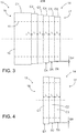
- Figure 3 shows in an exaggerated manner a lower tool bushing 13 an outer periphery 14 of which comprises six cylindrical sections C1 - C6 with differing diameters D1 - D6.
- Nominal outer diameter of the bushing depends on the size and capacity of the breaking hammer and may typically be between 150 - 250 mm.
- An inner periphery 15 of the bushing serves as a bearing surface against a breaking tool.
- a first cylindrical section C1 at a first end 16 or lower end of the bushing has the greatest diameter D1 and the opposite second end 17 or upper end has the smallest diameter D6.
- the outer surface of the bushing 13 is multi-stepped or multi-shouldered. Step height SH between adjacent shoulders may be 0.1 - 1.0 mm, for example.
- each of the cylindrical sections C1 - C6 or shoulders has an effective axial shoulder length L, which may be 20 - 60 mm.
- the lower tool bushing 13 has an extension portion 18 axial length of which may be multiple relative to the effective axial shoulder length L, and which may protrude from the bushing housing 1, as it is shown in Figure 2 .
- Figure 4 shows in an exaggerated manner a three-stepped tool bushing 13.
- the basic features of the bushing 13 of Figure 4 correspond to the bushing 13 of Figure 3 except that the first cylindrical section C1 is without any extension portion 18.
- Figure 5 discloses a tool bushing 13 basic structure of which is in accordance with the one shown in Figure 3 .
- an axial alignment groove 19 and a transverse locking groove 20 are shown.
- Number of alignment grooves 19 and locking grooves 20 may be two or more so that the bushing 13 has two or more alternative angular positions relative to central axis 21 of the bushing 13.
- the bushing 13 is turnable 90°, for example, as it is indicated by an arrow 22.
- Figure 6 discloses in a simplified manner a lower end A of the breaking hammer.
- a tool bushing 13 is mounted inside a bushing housing 12.
- Mating surfaces of the bushing 13 and the bushing housing 12 are provided with the multi-shouldered formations as described in this patent application. For clarity reasons the surfaces are shown without the stepped structure.
- At a second end portion 17 of the bushing 13 there is one or more alignment grooves 19 adapted to receive protruding alignment pins 25, such as screws.
- Fastening of the bushing 13 is based on friction mounting, but there may be a second fastening system, namely a transverse locking pin 26 arrangement.
- a tool seal 27 which is sealing ring arranged partly inside a sealing groove formed on inner periphery of the bushing 13 at the first end portion 16 of the bushing 13.
- Figure 6 further discloses that lubricating agent may be conveyed through a conduct 28 to a lubricating groove 23 wherefrom the lubricating agent may pass through lubricating holes 24 to a gap between the tool 6 and the bushing 13.
- An outer edge of the second end of the bushing 13 has a chamfer 29 for aligning purpose.
- Figure 7 illustrates mounting of a four-stepped lower tool bushing 13 by means of a pressing device 30, which may be a hydraulic jack having a piston 31 with maximum stroke length defining maximum mounting length ML.
- the bushing 13 has four cylinder sections C1 - C4 and each of them has axial length AL which is equal or shorter than the maximum mounting length ML.
- Figure 8 shows steps of a maintenance process of a tool bushing.
Landscapes
- Engineering & Computer Science (AREA)
- Mechanical Engineering (AREA)
- Mining & Mineral Resources (AREA)
- Civil Engineering (AREA)
- General Engineering & Computer Science (AREA)
- Structural Engineering (AREA)
- Percussive Tools And Related Accessories (AREA)
- Motor Or Generator Frames (AREA)
Abstract
Description
- The invention relates to a lower tool bushing of a breaking hammer. The tool bushing is a sleeve-like piece which is located inside a bushing housing at a lower end portion of a frame of the breaking hammer. A tool of the breaking hammer passes through the tool bushing and an inner surface of the bushing serves as a bearing surface for the tool. Fastening of the tool bushing is based at least partly to mutual sizes of an outer diameter of the bushing and an inner diameter of the bushing housing, whereby friction locking is utilized.
- The invention further relates to a bushing arrangement of a breaking hammer, and further to a breaking hammer and a method of mounting a tool bushing of a breaking hammer.
- The field of the invention is defined more specifically in the preambles of the independent claims.
- Breaking hammers are used to break hard materials, such as rock, concrete, and the like. The breaking hammer comprises a percussion device for generating impact pulses to a breaking tool connectable to the breaking hammer. The tool is supported to a frame of the breaking hammer by means of one or more tool bushings, which are sleeve-like objects through which the tool passes and reciprocates during its operation. At a lower end of the breaking hammer there is a lower tool bushing, which is subjected to significant transverse loadings during the breaking. The lower tool bushing is also subjected to wear because of the reciprocating tool movement, and further, because impurities may pass between the tool and the bushing despite of protective tool seals. Thus, especially the lower tool bushing may deform and wear whereby it needs to be changed time to time. The lower end portion of the frame is typically designed so that the lower tool bushing can be changed without need for extensive dismantling measures. The tool bushing is typically locked inside the bushing housing by using friction locking principle and interference fitting between the bushing and the bushing housing. However, the known solutions have drawbacks relating to dismounting and mounting of the tool bushings. The known solutions have shown to be time consuming and laborious, and sometimes the replacement work is impossible to execute in filed circumstances and without extensive dismantling measures and tooling.
- An object of the invention is to provide a novel and improved lower tool bushing of a breaking hammer. A further object is to provide a novel and improved tool bushing arrangement, a breaking hammer and a method of mounting a tool bushing, which all aim to facilitate maintenance of the breaking hammer.
- The tool bushing according to the invention is characterized by the characterizing features of the first independent apparatus claim.
- The tool bushing arrangement according to the invention is characterized by the characterizing features of the second independent apparatus claim.
- The breaking hammer according to the invention is characterized by the characterizing features of the third independent apparatus claim.
- The method according to the invention is characterized by the characterized features of the independent method claim.
- An idea of the disclosed solution is that the tool bushing is intended to be fastened inside a bushing housing predominantly by means of friction fastening generated during mounting between outer surfaces of the tool bushing and inner surfaces of the bushing housing. Further, outer dimensions of the tool bushing are arranged to increase stepwise towards a front or first end of the tool bushing. In other words, the tool bushing has a multi-stepped configuration and has three or more cylinder sections with differing diameters formed in successive order. The outer surface of the tool bushing is multi-shouldered. Correspondingly, the bushing housing is provided with corresponding inner surface formation so that the bushing housing is capable to receive the tool bushing and may form several friction locking sections between the opposing inner and outer shoulders.
- An advantage of the disclosed solution is that mounting of the tool bushing is facilitated when several stepped locking shoulders are used. Total locking force for the tool bushing is generated on several stepped shoulders, whereby axial mounting length of the bushing may be short. Great axial forces are required in the mounting process and generating short mounting movement with pressing and pulling devices is significantly easier than forming long movements with great forces. Since the total axial length of the tool bushing is divided into several successive shoulders, there influences frictional forces at all shoulder sections of the bushing, and still the mounting length may be short. Thanks to the disclosed multi-shoulder structure, the bushing has easy removal and mounting features, whereby the lower tool bushing can be serviced in field conditions and with the help of reasonable mounting tooling. Normally the dismounting and mounting can be executed by subjecting pulling/pushing forces to the bushing and no time consuming heating/cooling measures for generating thermal expansion are required, whereby maintenance work is facilitated and made quicker. One additional advantage is that the friction mounting of the bushing tolerates possible minor axial movements of the bushing without losing the mounting force since the solution is based on the use of cylindrical surfaces having axial lengths, whereas in some prior art solutions relating to tapered contact surfaces the locking force is vulnerable to any kind of axial movement. A possible additional advantage of the disclosed solution is that when the bushing is fitted firmly without a clearance to the bushing housing, impurities and moisture are effectively prevented to enter inside the structure of the breaking hammer resulting thereby longer operating life of the breaking hammer and lower need for service and downtime.
- Further, the cylindrical mating surfaces of the tool bushing assembly are relatively easy to machine on the surfaces of the tool bushing and the bushing housing, whereas forming accurate tapered surfaces disclosed in some prior art solutions is more complicated and expensive.
- According to an embodiment, the multi-stepped tool bushing has six, seven or even more stepped cylindrical sections following each other and having stepwise increasing diameters. The number of the successive cylindrical sections may be in relation to total axial length and size of the tool bushing. It can be stated as a thumb rule that the longer and greater in size the bushing is, the greater amount of shoulders it comprises.
- According to an embodiment, mutual diameters of the tool bushing and the bushing housing are dimensioned so that no radial clearance_exists in the installed state between the mating cylindrical sections of the tool bushing and the bushing housing.
- According to an embodiment, the diameters of the shoulders of the tool bushing are dimensioned according to interference fitting tolerances. Then, a light interference fit may be utilized in the mounting. However, even though diameters of the bushing and the bushing housing were dimensioned to have a very small gap, depending on manufacturing tolerances, the tool bushing would still remain firmly in place by means of friction forces since there exists typically at least minor deviations in cylindrical shapes of the nested surfaces of the bushing arrangement. The disclosed interference fitting is advantageous since it allows dismounting and mounting in field conditions and without use of extensive mounting tooling.
- According to an embodiment, the diameters of the shoulders of the tool bushing are dimensioned according to tight-fitting tolerances. This embodiment may be utilized in special cases when sufficiently great mounting forces can be generated and heating/cooling means are available.
- According to an embodiment, a front edge of the second end of the tool bushing is provided with a chamfer. The chamfer aligns the tool bushing relative to the bushing housing at the beginning of the mounting of the bushing. The initial alignment may be done manually.
- According to an embodiment, the tool bushing comprises at least one peripheral lubricating groove on the outer periphery, and the lubricating groove is provided with several radial through holes extending from the outer periphery to the inner periphery thereby forming passages for lubricating agent. The lubricating means allow lubricating grease to be fed to bearing surfaces so that longer service life is achieved.
- According to an embodiment, the inner periphery of the first shoulder of the tool bushing comprises a seal groove which is located at the first end portion of the tool bushing and is configured to receive a sealing ring for sealing a radial gap between the breaking tool and the tool bushing.
- According to an embodiment, step height of the shoulders is dimensioned to be 0,1 - 1,0 mm. Thereby, sizes of diameters of every two successive cylindrical sections differ 0,2 - 2 mm from each other.
- According to an embodiment, each shoulder has an effective axial shoulder length dimension of which is 20 - 60 mm. The axial shoulder length may be dimensioned according to stroke length of a hydraulic jack used for the dismounting and mounting. Thereby mounting length of the tool bushing is 20 - 60 mm and total length of the tool bushing is several times greater than the mounting length, typically at least 200 mm. The generated friction fastening extends from end to end of the tool bushing, whereby there needs to be several shoulders for providing desired fitting for the total length of the tool bushing.
- According to an embodiment, at the first end of tool bushing there is a first shoulder and several following shoulders are located between the first shoulder and the second end. Dimensions of axial lengths of the shoulders following the first shoulder are dimensioned to be 20 - 60 mm.
- According to an embodiment, at the first end of the tool bushing there is a first shoulder having an actual axial shoulder length greater than the effective axial shoulder length of the first shoulder. Actual physical length of the first shoulder is 2 - 5 times greater than the length of the other shoulders. In other words, the first shoulder may comprise an extra axial portion extending outside the outermost portion of the bushing housing.
- According to an embodiment, the tool bushing is without the extra length of the first shoulder disclosed in the previous embodiment. Then the lowermost shoulder with the greatest diameter may have the same axial length as the other shoulders, whereby the tool bushing does not protrude from the bushing housing.
- According to an embodiment, on the outer surface of the tool bushing is at least one axial alignment groove extending from the second end a limited axial length towards the first end. The alignment groove may receive a transverse alignment screw or pin mounted to the bushing housing. The alignment groove and pin arrangement is advantageous when the mounting system of the tool bushing comprises a locking pin. Then, the alignment system ensures already at the beginning of the mounting that the tool bushing has correct angular position relative to the bushing housing so that when the bushing is pressed inside the bushing housing, locking pin grooves of the bushing and the bushing housing match with each other and form a locking pin opening capable to receive the locking pin.
- According to an embodiment, the second end portion of the tool bushing is provided with at least two axial alignment grooves allowing the tool bushing to be aligned into at least two alternative rotational positions inside the bushing housing. The alignment grooves may be disposed at 90° relative to one another. This way the alignment grooves may determine desired alternative mounting positions for the bushing and may thereby facilitate maintenance of the lower tool bushing.
- According to an embodiment, the axial length of the at least one axial alignment groove is dimensioned to be greater than the mentioned effective axial shoulder length and extends thereby axially from the second end over at least one shoulder.
- According to an embodiment, the tool bushing arrangement comprises an additional locking system based on shape locking. Then, on the outer surface of the tool bushing there is a transverse locking groove, which is located at a section between the second end and longitudinal middle point of the tool bushing. The bushing housing comprises a similar transverse groove at the same location whereby the grooves form together an opening, which is configured to receive a transverse locking pin when the bushing is installed inside the bushing housing. In normal operation the disclosed friction forces keep the bushing firmly immovable inside the bushing housing and the locking pin arrangement only secures the mounting.
- According to an embodiment, the outer surface of the tool bushing comprises at least two locking grooves which are located on a same transverse plane relative to the longitudinal axis of the tool bushing and which locking grooves are positioned at 90° relative to one another. An advantage of the crossing locking grooves is that the tool bushing may be turned 90° when the inner surface of the tool bushing wears during the use. By turning the tool bushing operating life of the tool bushing may be extended. The above mentioned alignment system comprising two selectable alignment grooves may operate in co-operation with the pin locking system comprising two selectable locking grooves.
- According to an embodiment, the solution relates to a tool bushing arrangement of a breaking hammer. A bushing housing comprises an inner space for receiving the lower tool bushing. The bushing and the bushing housing are both provided with stepped surfaces which match to each other and form several friction locking pairs. Diameters of the stepped surfaces are dimensioned so that there are no mutual radial clearances between the mating cylinder surfaces. Then the bushing is retained firmly in place and there is no need for sealing elements between the bushing and the bushing housing.
- According to an embodiment, between each shoulder of the tool bushing and respective mating cylindrical inner surface of the bushing housing surrounding the respective shoulder is a light interference fit or interference fit, whereby the friction fitting exists on several diameters.
- According to an embodiment, the tool bushing is retained inside the bushing housing by means of a press fit. Axial mounting length of the press fit is 20 - 60 mm.
- According to an embodiment, the disclosed solution relates to a breaking hammer, comprising: a front head defining a bore therein, an inner surface of the bore having a first multi shouldered surface with at least three successive shoulders each provided with different diameters; and a lower bushing capable of being positioned within the bore, an outer surface of the lower bushing having a second multi shouldered surface matching with the first multi shouldered surface.
- According to an embodiment, the solution relates to a method of mounting a tool bushing of a breaking hammer. The method comprises inserting the above disclosed multi-stepped tool bushing inside a bushing housing and retaining the bushing predominantly by means of a friction fitting between the several mating cylindrical surfaces of the tool bushing and the bushing housing. The bushing is forced inside the bushing housing and then the needed retaining forces are generated. The bushing may be mounted by using two successive pushing phases. The bushing is in a first pushing phase pushed manually partly inside the bushing housing, and is in a second pushing phase pushed with force into a final installation position by means of a pressing_device. Further, the second pushing with the pressing device is extended for an axial mounting length, magnitude of which is 20 - 60 mm. An advantage of the short mounting length is that size and weight of the pressing device may be reasonable and the device is easy to handle manually.
- According to an embodiment, the mounting and dismounting is executed by a portable pressing and pulling device maximum movement or stroke length of which is 60 mm.
- According to an embodiment, the method comprise steps for changing angular position of an existing tool bushing. Then the method comprises pulling an already installed tool bushing backwards from the bushing housing for a longitudinal distance, magnitude of which is greater than the mentioned axial mounting length. The tool bushing may be left partly inside the bushing housing, but the friction fastening is loosened. Thereafter, the loosened tool bushing is turned relative to the central axis of the tool bushing to a different angular position compared to the previous angular position. When being correctly positioned, the tool bushing may be pushed longitudinally back inside the bushing housing whereby the tool bushing is secured into a new angular position by means of friction forces. Wearing of the bearing surface of the tool bushing is typically not evenly distributed, whereby an advantage of this embodiment is that by turning the bushing into different position, operating life of the bushing may be longer. The change is fast and easy to execute when the disclosed multi-stepped solution is utilized.
- According to an embodiment, contact surfaces between the bushing housing and the tool bushing are without any sealing elements. The interference fitting between these objects ensures that no impurities may penetrate through the connection inside the frame. Further, the fitting remains impermeable to dirt even though any minor axial movement would occur between the mating surfaces.
- Let it be mentioned that the disclosed tool bushing is also suitable for other types of breaking hammers than those disclosed in this patent application. The percussion or impact device may differ from the one shown, for example. Around the frame of the breaking hammer may or may not be a protective casing surrounding the frame.
- The above-disclosed embodiments can be combined to form desired solutions provided with necessary features disclosed.
- Some embodiments are described in more detail in the accompanying drawings, in which
-
Figure 1 is a schematic side view of an excavator, which is provided with a breaking hammer, -
Figure 2 is a schematic and sectional side view of a percussion device of a breaking hammer, -
Figure 3 is a schematic side view of a lower tool bushing comprising six successive cylindrical outer sections with differing diameters, -
Figure 4 is a schematic side view of another lower tool bushing comprising three cylindrical outer sections or shoulders, -
Figure 5 is a schematic and perspective view of a tool bushing and also shows an axial alignment groove and a transverse locking groove, -
Figure 6 is a schematic and sectional side view of a lower end portion of the breaking hammer, -
Figure 7 is a schematic side view of a mounting setting comprising a hydraulic jack, and -
Figure 8 is a schematic diagram showing steps relating to change or turning measures of the tool bushing. - For the sake of clarity, the Figures show some embodiments of the disclosed solution in a simplified manner. In the Figures, like reference numerals identify like elements.
-
Figure 1 shows a breaking hammer 1 arranged on a free end of a boom 2 in a workingmachine 3, such as an excavator. Alternatively, the boom 2 may be arranged on any movable carriage or on a fixed platform of a crushing apparatus. The breaking hammer 1 comprises apercussion device 4 for generating impact pulses. The breaking hammer 1 may be pressed by means of the boom 2 againstmaterial 5 to be broken and impacts may be simultaneously generated with thepercussion device 4 to atool 6 connected to the breaking hammer 1. Thetool 6 transmits the impact pulses to thematerial 5 to be broken. Thepercussion device 4 may be hydraulic, whereby it may be connected to the hydraulic system of the working machine 2. Alternatively, thepercussion device 4 may be electrically or pneumatically powered. The impact pulses may be generated in thepercussion device 4 by means of a percussion element, such as percussion piston, that may be moved back and forth in the impact direction and return direction under the influence of hydraulic fluid. Further, the breaking hammer 1 may comprise aprotective casing 7, inside which thepercussion device 4 may be located. At a lower end of the breaking hammer, i.e. at the tool side end, is a lowertool bushing arrangement 8 for bearing thetool 6 to a frame of the breaking hammer. Thetool bushing arrangement 8 comprises a tool bushing disclosed in this patent application. -
Figure 2 discloses a structure of apercussion device 4 of a breaking hammer 1. The breaking hammer comprises a lower end A at a tool side end and an upper end B. Apercussion device 4 may comprise apercussion piston 9 arranged to move to and fro relative to aframe 10 of thepercussion device 4. Animpact surface 11 of thepercussion piston 9 is arranged to strike an upper end of a tool, which is not shown inFigure 2 . The tool is allowed to move in the axial direction P during the use. Theframe 10 may comprise anupper frame part 10a and alower frame part 10b. - At the lower end of the
lower frame part 10b of the breaking hammer 1 is abushing housing 12 configured to receive a sleeve-likelower tool bushing 13. The tool is also supported by means of anupper tool bushing 14, which is mounted in place when thelower frame 10b is detached. The tool is configured to pass through the lower andupper tool bushings lower tool bushing 13 is subjected to greater mechanical forces and wear than theupper tool bushing 14, whereby the lower tool bushing needs to be serviced and changed more often. Since thebushing housing 12 of thelower tool bushing 13 opens towards the lower end A of the breaking hammer 1, thebushing 13 can be dismounted without dismantling the basic structure of theframe 10. -
Figure 3 shows in an exaggerated manner alower tool bushing 13 anouter periphery 14 of which comprises six cylindrical sections C1 - C6 with differing diameters D1 - D6. Nominal outer diameter of the bushing depends on the size and capacity of the breaking hammer and may typically be between 150 - 250 mm. Aninner periphery 15 of the bushing serves as a bearing surface against a breaking tool. As can be noted a first cylindrical section C1 at afirst end 16 or lower end of the bushing has the greatest diameter D1 and the oppositesecond end 17 or upper end has the smallest diameter D6. Thus, the outer surface of thebushing 13 is multi-stepped or multi-shouldered. Step height SH between adjacent shoulders may be 0.1 - 1.0 mm, for example. Further, each of the cylindrical sections C1 - C6 or shoulders has an effective axial shoulder length L, which may be 20 - 60 mm. - In
Figures 2 and3 thelower tool bushing 13 has anextension portion 18 axial length of which may be multiple relative to the effective axial shoulder length L, and which may protrude from the bushing housing 1, as it is shown inFigure 2 . -
Figure 4 shows in an exaggerated manner a three-steppedtool bushing 13. The basic features of thebushing 13 ofFigure 4 correspond to thebushing 13 ofFigure 3 except that the first cylindrical section C1 is without anyextension portion 18. -
Figure 5 discloses atool bushing 13 basic structure of which is in accordance with the one shown inFigure 3 . However, inFigure 5 also anaxial alignment groove 19 and atransverse locking groove 20 are shown. Number ofalignment grooves 19 and lockinggrooves 20 may be two or more so that thebushing 13 has two or more alternative angular positions relative tocentral axis 21 of thebushing 13. Thus, thebushing 13 is turnable 90°, for example, as it is indicated by anarrow 22. Further, on the outer periphery of thebushing 13 may be a lubricatinggroove 23 andseveral lubricating holes 24 passing through wall of thebushing 13. -
Figure 6 discloses in a simplified manner a lower end A of the breaking hammer. Atool bushing 13 is mounted inside abushing housing 12. Mating surfaces of thebushing 13 and thebushing housing 12 are provided with the multi-shouldered formations as described in this patent application. For clarity reasons the surfaces are shown without the stepped structure. At asecond end portion 17 of thebushing 13 there is one ormore alignment grooves 19 adapted to receive protruding alignment pins 25, such as screws. Fastening of thebushing 13 is based on friction mounting, but there may be a second fastening system, namely atransverse locking pin 26 arrangement. Between atool 6 and thebushing 13 is atool seal 27, which is sealing ring arranged partly inside a sealing groove formed on inner periphery of thebushing 13 at thefirst end portion 16 of thebushing 13.Figure 6 further discloses that lubricating agent may be conveyed through aconduct 28 to alubricating groove 23 wherefrom the lubricating agent may pass through lubricatingholes 24 to a gap between thetool 6 and thebushing 13. An outer edge of the second end of thebushing 13 has achamfer 29 for aligning purpose. -
Figure 7 illustrates mounting of a four-steppedlower tool bushing 13 by means of apressing device 30, which may be a hydraulic jack having apiston 31 with maximum stroke length defining maximum mounting length ML. Thebushing 13 has four cylinder sections C1 - C4 and each of them has axial length AL which is equal or shorter than the maximum mounting length ML. -
Figure 8 shows steps of a maintenance process of a tool bushing. These issues have already been discussed above in this patent application. - The drawings and the related description are only intended to illustrate the idea of the invention. In its details, the invention may vary within the scope of the claims.
Claims (15)
- A tool bushing (13) of a breaking hammer (1), wherein
the tool bushing (13) is a sleeve-like piece having an inner periphery (15), an outer periphery (14) and an axial length;
the inner periphery (15) is serving as a bearing surface and is intended to be towards a breaking tool (6) to be supported, and the outer periphery (14) is intended to be facing a bushing housing (12); and
the tool bushing (13) has a first end (16) with a first outer diameter and a second end (17) with a second outer diameter, and wherein the first diameter is greater than the second diameter;
characterized in that
the outer periphery (14) of the tool bushing (13) has multi-shoulder configuration comprising at least three successive cylindrical sections (C1 - C6) with differing diameters (D1 - D6) and wherein sizes of the diameters of the shoulders are dimensioned to increase step by step towards the first end (16). - The tool bushing as claimed in claim 1, characterized in that
the outer periphery (14) of the tool bushing (13) is stepped into at least six successive cylindrical sections (C1 - C6) diameters (D1 - D6) of which are different in size. - The tool bushing as claimed in claim 1 or 2, characterized in that
step height (SH) of the shoulders is 0,1 - 1,0 mm, whereby sizes of diameters (D1 - D6) of every two successive cylindrical sections (C1 - C6) differ 0,2 - 2 mm from each other. - The tool bushing as claimed in any one of the preceding claims 1 -3, characterized in that
each shoulder has an effective axial shoulder length (L) dimension of which is 20 - 60 mm. - The tool bushing as claimed in any one of the preceding claims 1 to 4, characterized in that
on the outer surface (14) of the tool bushing (13) is at least one axial alignment groove (19) extending from the second end (17) a limited axial length towards the first end (16). - The tool bushing as claimed in any one of the preceding claims 1 -5, characterized in that
the outer surface (14) of the tool bushing (13) is provided with at least one transverse locking groove (20), which is located at a section between the second end (17) and longitudinal middle point of the tool bushing (13), and is intended to partly receive a transverse locking pin (26) in an installed state of the tool bushing (13). - A tool bushing arrangement of a breaking hammer (1) comprising:a breaking tool (6), which is an elongated piece;a tool bushing (13), which is located around the breaking tool (6) and comprises at least one cylindrical outer surface;a bushing housing (12), which is configured to receive the tool bushing (13) inside at least one cylindrical inner surface;and wherein the tool bushing (13) is predominantly retained by means of a friction fitting between the cylindrical surfaces of the tool bushing (12) and the bushing housing (13);characterized in thatthe tool bushing (13) is in accordance with claims 1 to 6;the bushing housing (12) has a corresponding multi-shouldered configuration with several successive cylindrical inner surfaces with differing diameters for receiving the several cylindrical outer surfaces (C1 - C6) of the multi-shouldered tool bushing (13);and wherein the diameters (D1 - D6) of the several outer cylindrical surfaces (C1 - C6) of the tool bushing (13) and the diameters of the mating inner cylindrical surfaces of the bushing housing (12) are dimensioned to be without mutual radial clearances.
- The tool bushing arrangement as claimed in claim 7, characterized in that
between each shoulder of the tool bushing (13) and respective mating cylindrical inner surface of the bushing housing (12) surrounding the respective shoulder is a light interference fit or interference fit, whereby the friction fitting exists on several diameters (D1 - D6). - The tool bushing arrangement as claimed in claim 7 or 8, characterized in that
the tool bushing (13) is retained by means of a press fit and axial mounting length (ML) of the press fit is 20 - 60 mm. - A breaking hammer (1), comprising:a percussion device (4) comprising a frame (10) and an impact element (9) arranged inside the frame (10);a breaking tool (6) connectable to the percussion device (4) and to protrude from the frame (10);a tool bushing (13), which is located around the breaking tool (6) and comprises at least one cylindrical outer surface;a bushing housing (12), which is located at a tool side end of the frame (10) and is configured to receive the tool bushing (13) inside at least one cylindrical inner surface;and wherein the tool bushing (12) is predominantly retained by means of a friction fitting between the cylindrical surfaces of the tool bushing (12) and the bushing housing (13);characterized in thatthe tool bushing (13) is in accordance with claims 1 to 6;the bushing housing (12) has a corresponding multi-shouldered configuration with several successive cylindrical inner surfaces with differing diameters for receiving the several cylindrical outer surfaces of the multi-shouldered tool bushing (13);and wherein the diameters (D1 - D6) of the several outer cylindrical surfaces of the tool bushing (13) and the diameters of the mating inner cylindrical surfaces of the bushing housing (12) are dimensioned to be without mutual radial clearances.
- A method of mounting a tool bushing (13) of a breaking hammer (1), the method comprising:providing a tool side lower end of the breaking hammer (1) with at least one tool bushing (13);arranging the tool bushing (13) inside a bushing housing (12) of the breaking hammer (1); andretaining the tool bushing (13) predominantly by means of a friction fitting between cylindrical surfaces of the tool bushing (13) and the bushing housing (12);characterized byproviding the tool bushing (13) with at least three successive cylindrical outer surfaces and providing the bushing housing (12) with at least three mating cylindrical inner surfaces;mounting the tool bushing (13) into the bushing housing (12) by using two successive pushing phases, wherein the tool bushing (13) is in a first pushing phase pushed manually partly inside the bushing housing (12), and is in a second pushing phase pushed into a final installation position by means of a pressing device (30); andextending pushing of the tool bushing (13) in the second pushing phase for an axial mounting length (ML) magnitude of which is 20 - 60 mm.
- The method according to claim 11, characterized by over dimensioning all cylindrical outer surfaces of the tool bushing (13) relative to the cylindrical inner surfaces of the bushing housing (12); and
forcing the tool bushing (13) into the bushing housing (12) by means of the pressing device (30), and generating thereby a press fit between the cylindrical surfaces of the tool bushing (13) and the bushing housing (12). - The method according to claim 11 or 12, characterized by
using in the assembly a portable hydraulic press or jack (30) with maximum stroke length of 60 mm. - The method according to any one of the preceding claims 11 - 13, characterized by
aligning the tool bushing (13) relative to the bushing housing (12) in the first pushing phase by setting an axial alignment groove (19) of the tool bushing (13) in line with a protruding alignment pin (25) of the bushing housing (12) before initiating the second pushing phase. - The method according to any one of the preceding claims 11 - 14, characterized by
pulling an already installed tool bushing (13) backwards from the bushing housing (12) for a longitudinal distance magnitude of which is greater than the mentioned axial mounting length (ML) and without totally retracting the tool bushing (13) from the bushing housing (12);
turning (22) the loosened tool bushing (13) relative to the central axis (21) of the tool bushing (13) to a different angular position compared to the previous position; and
pushing the tool bushing (13) longitudinally back into the bushing housing (12) whereby the tool bushing (13) is secured into a new angular position.
Priority Applications (4)
| Application Number | Priority Date | Filing Date | Title |
|---|---|---|---|
| EP18171764.6A EP3566817B1 (en) | 2018-05-11 | 2018-05-11 | Tool bushing, tool bushing arrangement, breaking hammer and mounting method |
| KR1020190052403A KR20190129725A (en) | 2018-05-11 | 2019-05-03 | Tool bushing, breaking hammer and mounting method |
| US16/403,433 US11478914B2 (en) | 2018-05-11 | 2019-05-03 | Tool bushing, breaking hammer and mounting method |
| CN201910375107.7A CN110468898B (en) | 2018-05-11 | 2019-05-07 | Tool bushing, breaking hammer and mounting method |
Applications Claiming Priority (1)
| Application Number | Priority Date | Filing Date | Title |
|---|---|---|---|
| EP18171764.6A EP3566817B1 (en) | 2018-05-11 | 2018-05-11 | Tool bushing, tool bushing arrangement, breaking hammer and mounting method |
Publications (2)
| Publication Number | Publication Date |
|---|---|
| EP3566817A1 true EP3566817A1 (en) | 2019-11-13 |
| EP3566817B1 EP3566817B1 (en) | 2022-08-17 |
Family
ID=62152415
Family Applications (1)
| Application Number | Title | Priority Date | Filing Date |
|---|---|---|---|
| EP18171764.6A Active EP3566817B1 (en) | 2018-05-11 | 2018-05-11 | Tool bushing, tool bushing arrangement, breaking hammer and mounting method |
Country Status (4)
| Country | Link |
|---|---|
| US (1) | US11478914B2 (en) |
| EP (1) | EP3566817B1 (en) |
| KR (1) | KR20190129725A (en) |
| CN (1) | CN110468898B (en) |
Families Citing this family (1)
| Publication number | Priority date | Publication date | Assignee | Title |
|---|---|---|---|---|
| CN114235461B (en) * | 2021-11-09 | 2023-05-16 | 刘文心 | Breaking hammer for geological survey sampling |
Citations (4)
| Publication number | Priority date | Publication date | Assignee | Title |
|---|---|---|---|---|
| GB103619A (en) * | 1916-09-05 | 1917-02-01 | Heinrich Christiansen | Improvements relating to Pneumatically Operated Percussion Tools. |
| GB1537326A (en) * | 1975-03-13 | 1978-12-29 | Duss Maschf | Percussion hammer |
| US20130056940A1 (en) * | 2011-02-23 | 2013-03-07 | Hilti Aktiengesellschaft | Tool receptacle |
| EP2873489A1 (en) * | 2013-11-13 | 2015-05-20 | Sandvik Mining and Construction Oy | Impact device and method of dismounting the same |
Family Cites Families (22)
| Publication number | Priority date | Publication date | Assignee | Title |
|---|---|---|---|---|
| FR2355617A1 (en) * | 1975-12-18 | 1978-01-20 | Montabert Roger | PERCUSSION MACHINE |
| US6510904B1 (en) * | 2000-05-26 | 2003-01-28 | Nippon Pneumatic Mfg. Co., Ltd. | Protected tool bushing for an impact hammer |
| US7144210B2 (en) * | 2004-01-21 | 2006-12-05 | Kennametal Inc. | Tool holder |
| JP4509890B2 (en) | 2005-08-19 | 2010-07-21 | 株式会社マキタ | Impact type work tool |
| FI121221B (en) * | 2008-11-20 | 2010-08-31 | Sandvik Mining & Constr Oy | Rock drill and axial bearing module |
| CN102294674A (en) | 2010-12-02 | 2011-12-28 | 莫雪松 | Method for quickly dismantling drill rod bush of drill rod base assembly of hydraulic breaking hammer |
| US9102045B2 (en) * | 2011-09-29 | 2015-08-11 | Caterpillar Inc. | System and method for easy removal of hydraulic hammer bushing |
| KR101290789B1 (en) | 2011-10-17 | 2013-07-30 | 주식회사수산중공업 | a lubricating apparatus for contact piston of hydraulic breaker |
| CN202438351U (en) | 2012-02-28 | 2012-09-19 | 天津辰龙重工机械有限公司 | Hydraulic breaking hammer |
| DE102012207651A1 (en) * | 2012-05-08 | 2013-11-14 | Aesculap Ag | Quick-coupling |
| DE102012013409A1 (en) * | 2012-05-23 | 2013-11-28 | Atlas Copco Construction Tools Gmbh | impact device |
| US9151386B2 (en) * | 2013-03-15 | 2015-10-06 | Caterpillar Inc. | Accumulator membrane for a hydraulic hammer |
| CN203361227U (en) | 2013-07-22 | 2013-12-25 | 南通欧特建材设备有限公司 | Novel knapping assembly of hydraulic knapper |
| US10201894B2 (en) * | 2015-09-14 | 2019-02-12 | Caterpillar Inc. | Collet hydraulic hammer bushing |
| US10363651B2 (en) * | 2015-09-28 | 2019-07-30 | Caterpillar Inc. | Hammer assembly |
| US10035251B2 (en) * | 2015-11-13 | 2018-07-31 | Caterpillar Inc. | Wear indicating system |
| CN105536933B (en) | 2015-12-14 | 2018-06-22 | 新乡市鼎力矿山设备有限公司 | A kind of wear-resistance protective sleeve on hammer of hammer crusher disk |
| CN105401609B (en) | 2015-12-16 | 2018-01-16 | 陶健 | The lower bushing of structure optimization on a kind of hydraulic breaking hammer |
| CN105909166B (en) | 2016-04-21 | 2017-11-03 | 西南石油大学 | Drilling speed synergy spiral two-stage composite impact device |
| US10226857B2 (en) * | 2016-10-19 | 2019-03-12 | Caterpillar Inc. | Reversible bushing |
| US20180126535A1 (en) * | 2016-11-04 | 2018-05-10 | Caterpillar Inc. | Magnetic retention device for a hydraulic hammer bushing |
| CN207110960U (en) | 2017-05-11 | 2018-03-16 | 能诚集团有限公司 | Churn drilling tools and the percussive drill with the churn drilling tools |
-
2018
- 2018-05-11 EP EP18171764.6A patent/EP3566817B1/en active Active
-
2019
- 2019-05-03 KR KR1020190052403A patent/KR20190129725A/en not_active Ceased
- 2019-05-03 US US16/403,433 patent/US11478914B2/en active Active
- 2019-05-07 CN CN201910375107.7A patent/CN110468898B/en active Active
Patent Citations (4)
| Publication number | Priority date | Publication date | Assignee | Title |
|---|---|---|---|---|
| GB103619A (en) * | 1916-09-05 | 1917-02-01 | Heinrich Christiansen | Improvements relating to Pneumatically Operated Percussion Tools. |
| GB1537326A (en) * | 1975-03-13 | 1978-12-29 | Duss Maschf | Percussion hammer |
| US20130056940A1 (en) * | 2011-02-23 | 2013-03-07 | Hilti Aktiengesellschaft | Tool receptacle |
| EP2873489A1 (en) * | 2013-11-13 | 2015-05-20 | Sandvik Mining and Construction Oy | Impact device and method of dismounting the same |
Also Published As
| Publication number | Publication date |
|---|---|
| US20190344417A1 (en) | 2019-11-14 |
| US11478914B2 (en) | 2022-10-25 |
| CN110468898A (en) | 2019-11-19 |
| KR20190129725A (en) | 2019-11-20 |
| CN110468898B (en) | 2022-09-06 |
| EP3566817B1 (en) | 2022-08-17 |
Similar Documents
| Publication | Publication Date | Title |
|---|---|---|
| US4717083A (en) | Hammer assembly for a rotary material crusher | |
| CA2869157C (en) | Impact device and method of dismounting the same | |
| EP1559515B1 (en) | Hydraulic hammer | |
| EP1930127B1 (en) | Method for fitting a beaking device tool with a bearing, breaking device and bearing of a breaking device | |
| US6510904B1 (en) | Protected tool bushing for an impact hammer | |
| FI121220B (en) | Rock drill and axial bearing module | |
| US20140262407A1 (en) | Hydraulic hammer having impact system subassembly | |
| US9102045B2 (en) | System and method for easy removal of hydraulic hammer bushing | |
| US9151386B2 (en) | Accumulator membrane for a hydraulic hammer | |
| EP2896778A1 (en) | Quick release down-the-hole hammer drill bit assembly | |
| US8757135B2 (en) | Splitting wedge | |
| EP4043152B1 (en) | Breaking hammer and method of supporting percussion piston | |
| EP3566817B1 (en) | Tool bushing, tool bushing arrangement, breaking hammer and mounting method | |
| US11280134B2 (en) | Ground drilling device, method for making a ground drilling device, method for maintaining a ground drilling device, and use of a ground drilling device | |
| FI121222B (en) | The rock drilling machine | |
| US2767957A (en) | Rock drill front end | |
| CN222746030U (en) | Impact device | |
| CN222065626U (en) | Quick disassembly and assembly structure of breaker hammer sheath | |
| AU698429B2 (en) | A piston construction for an axial bearing of a drilling machine | |
| CN216588445U (en) | Square drill rod assembly | |
| CN120139315A (en) | Quick disassembly and assembly structure of breaker hammer sheath | |
| GB2153704A (en) | Hammer assembly for a rotary material crusher | |
| CN120845053A (en) | Cutters and tunneling equipment | |
| CN121138718A (en) | A multi-directional control drilling guidance device |
Legal Events
| Date | Code | Title | Description |
|---|---|---|---|
| PUAI | Public reference made under article 153(3) epc to a published international application that has entered the european phase |
Free format text: ORIGINAL CODE: 0009012 |
|
| STAA | Information on the status of an ep patent application or granted ep patent |
Free format text: STATUS: THE APPLICATION HAS BEEN PUBLISHED |
|
| AK | Designated contracting states |
Kind code of ref document: A1 Designated state(s): AL AT BE BG CH CY CZ DE DK EE ES FI FR GB GR HR HU IE IS IT LI LT LU LV MC MK MT NL NO PL PT RO RS SE SI SK SM TR |
|
| AX | Request for extension of the european patent |
Extension state: BA ME |
|
| STAA | Information on the status of an ep patent application or granted ep patent |
Free format text: STATUS: REQUEST FOR EXAMINATION WAS MADE |
|
| 17P | Request for examination filed |
Effective date: 20200513 |
|
| RBV | Designated contracting states (corrected) |
Designated state(s): AL AT BE BG CH CY CZ DE DK EE ES FI FR GB GR HR HU IE IS IT LI LT LU LV MC MK MT NL NO PL PT RO RS SE SI SK SM TR |
|
| GRAP | Despatch of communication of intention to grant a patent |
Free format text: ORIGINAL CODE: EPIDOSNIGR1 |
|
| STAA | Information on the status of an ep patent application or granted ep patent |
Free format text: STATUS: GRANT OF PATENT IS INTENDED |
|
| INTG | Intention to grant announced |
Effective date: 20220506 |
|
| GRAS | Grant fee paid |
Free format text: ORIGINAL CODE: EPIDOSNIGR3 |
|
| GRAA | (expected) grant |
Free format text: ORIGINAL CODE: 0009210 |
|
| STAA | Information on the status of an ep patent application or granted ep patent |
Free format text: STATUS: THE PATENT HAS BEEN GRANTED |
|
| AK | Designated contracting states |
Kind code of ref document: B1 Designated state(s): AL AT BE BG CH CY CZ DE DK EE ES FI FR GB GR HR HU IE IS IT LI LT LU LV MC MK MT NL NO PL PT RO RS SE SI SK SM TR |
|
| REG | Reference to a national code |
Ref country code: CH Ref legal event code: EP |
|
| REG | Reference to a national code |
Ref country code: DE Ref legal event code: R096 Ref document number: 602018039310 Country of ref document: DE |
|
| REG | Reference to a national code |
Ref country code: IE Ref legal event code: FG4D |
|
| REG | Reference to a national code |
Ref country code: AT Ref legal event code: REF Ref document number: 1511871 Country of ref document: AT Kind code of ref document: T Effective date: 20220915 |
|
| REG | Reference to a national code |
Ref country code: SE Ref legal event code: TRGR |
|
| REG | Reference to a national code |
Ref country code: NL Ref legal event code: MP Effective date: 20220817 |
|
| REG | Reference to a national code |
Ref country code: LT Ref legal event code: MG9D |
|
| PG25 | Lapsed in a contracting state [announced via postgrant information from national office to epo] |
Ref country code: RS Free format text: LAPSE BECAUSE OF FAILURE TO SUBMIT A TRANSLATION OF THE DESCRIPTION OR TO PAY THE FEE WITHIN THE PRESCRIBED TIME-LIMIT Effective date: 20220817 Ref country code: PT Free format text: LAPSE BECAUSE OF FAILURE TO SUBMIT A TRANSLATION OF THE DESCRIPTION OR TO PAY THE FEE WITHIN THE PRESCRIBED TIME-LIMIT Effective date: 20221219 Ref country code: NO Free format text: LAPSE BECAUSE OF FAILURE TO SUBMIT A TRANSLATION OF THE DESCRIPTION OR TO PAY THE FEE WITHIN THE PRESCRIBED TIME-LIMIT Effective date: 20221117 Ref country code: NL Free format text: LAPSE BECAUSE OF FAILURE TO SUBMIT A TRANSLATION OF THE DESCRIPTION OR TO PAY THE FEE WITHIN THE PRESCRIBED TIME-LIMIT Effective date: 20220817 Ref country code: LV Free format text: LAPSE BECAUSE OF FAILURE TO SUBMIT A TRANSLATION OF THE DESCRIPTION OR TO PAY THE FEE WITHIN THE PRESCRIBED TIME-LIMIT Effective date: 20220817 Ref country code: LT Free format text: LAPSE BECAUSE OF FAILURE TO SUBMIT A TRANSLATION OF THE DESCRIPTION OR TO PAY THE FEE WITHIN THE PRESCRIBED TIME-LIMIT Effective date: 20220817 Ref country code: FI Free format text: LAPSE BECAUSE OF FAILURE TO SUBMIT A TRANSLATION OF THE DESCRIPTION OR TO PAY THE FEE WITHIN THE PRESCRIBED TIME-LIMIT Effective date: 20220817 |
|
| REG | Reference to a national code |
Ref country code: AT Ref legal event code: MK05 Ref document number: 1511871 Country of ref document: AT Kind code of ref document: T Effective date: 20220817 |
|
| PG25 | Lapsed in a contracting state [announced via postgrant information from national office to epo] |
Ref country code: PL Free format text: LAPSE BECAUSE OF FAILURE TO SUBMIT A TRANSLATION OF THE DESCRIPTION OR TO PAY THE FEE WITHIN THE PRESCRIBED TIME-LIMIT Effective date: 20220817 Ref country code: IS Free format text: LAPSE BECAUSE OF FAILURE TO SUBMIT A TRANSLATION OF THE DESCRIPTION OR TO PAY THE FEE WITHIN THE PRESCRIBED TIME-LIMIT Effective date: 20221217 Ref country code: HR Free format text: LAPSE BECAUSE OF FAILURE TO SUBMIT A TRANSLATION OF THE DESCRIPTION OR TO PAY THE FEE WITHIN THE PRESCRIBED TIME-LIMIT Effective date: 20220817 Ref country code: GR Free format text: LAPSE BECAUSE OF FAILURE TO SUBMIT A TRANSLATION OF THE DESCRIPTION OR TO PAY THE FEE WITHIN THE PRESCRIBED TIME-LIMIT Effective date: 20221118 |
|
| PG25 | Lapsed in a contracting state [announced via postgrant information from national office to epo] |
Ref country code: SM Free format text: LAPSE BECAUSE OF FAILURE TO SUBMIT A TRANSLATION OF THE DESCRIPTION OR TO PAY THE FEE WITHIN THE PRESCRIBED TIME-LIMIT Effective date: 20220817 Ref country code: RO Free format text: LAPSE BECAUSE OF FAILURE TO SUBMIT A TRANSLATION OF THE DESCRIPTION OR TO PAY THE FEE WITHIN THE PRESCRIBED TIME-LIMIT Effective date: 20220817 Ref country code: ES Free format text: LAPSE BECAUSE OF FAILURE TO SUBMIT A TRANSLATION OF THE DESCRIPTION OR TO PAY THE FEE WITHIN THE PRESCRIBED TIME-LIMIT Effective date: 20220817 Ref country code: DK Free format text: LAPSE BECAUSE OF FAILURE TO SUBMIT A TRANSLATION OF THE DESCRIPTION OR TO PAY THE FEE WITHIN THE PRESCRIBED TIME-LIMIT Effective date: 20220817 Ref country code: CZ Free format text: LAPSE BECAUSE OF FAILURE TO SUBMIT A TRANSLATION OF THE DESCRIPTION OR TO PAY THE FEE WITHIN THE PRESCRIBED TIME-LIMIT Effective date: 20220817 Ref country code: AT Free format text: LAPSE BECAUSE OF FAILURE TO SUBMIT A TRANSLATION OF THE DESCRIPTION OR TO PAY THE FEE WITHIN THE PRESCRIBED TIME-LIMIT Effective date: 20220817 |
|
| REG | Reference to a national code |
Ref country code: DE Ref legal event code: R097 Ref document number: 602018039310 Country of ref document: DE |
|
| PG25 | Lapsed in a contracting state [announced via postgrant information from national office to epo] |
Ref country code: SK Free format text: LAPSE BECAUSE OF FAILURE TO SUBMIT A TRANSLATION OF THE DESCRIPTION OR TO PAY THE FEE WITHIN THE PRESCRIBED TIME-LIMIT Effective date: 20220817 Ref country code: EE Free format text: LAPSE BECAUSE OF FAILURE TO SUBMIT A TRANSLATION OF THE DESCRIPTION OR TO PAY THE FEE WITHIN THE PRESCRIBED TIME-LIMIT Effective date: 20220817 |
|
| PLBE | No opposition filed within time limit |
Free format text: ORIGINAL CODE: 0009261 |
|
| STAA | Information on the status of an ep patent application or granted ep patent |
Free format text: STATUS: NO OPPOSITION FILED WITHIN TIME LIMIT |
|
| PG25 | Lapsed in a contracting state [announced via postgrant information from national office to epo] |
Ref country code: AL Free format text: LAPSE BECAUSE OF FAILURE TO SUBMIT A TRANSLATION OF THE DESCRIPTION OR TO PAY THE FEE WITHIN THE PRESCRIBED TIME-LIMIT Effective date: 20220817 |
|
| 26N | No opposition filed |
Effective date: 20230519 |
|
| PG25 | Lapsed in a contracting state [announced via postgrant information from national office to epo] |
Ref country code: SI Free format text: LAPSE BECAUSE OF FAILURE TO SUBMIT A TRANSLATION OF THE DESCRIPTION OR TO PAY THE FEE WITHIN THE PRESCRIBED TIME-LIMIT Effective date: 20220817 |
|
| REG | Reference to a national code |
Ref country code: CH Ref legal event code: PL |
|
| PG25 | Lapsed in a contracting state [announced via postgrant information from national office to epo] |
Ref country code: MC Free format text: LAPSE BECAUSE OF FAILURE TO SUBMIT A TRANSLATION OF THE DESCRIPTION OR TO PAY THE FEE WITHIN THE PRESCRIBED TIME-LIMIT Effective date: 20220817 |
|
| GBPC | Gb: european patent ceased through non-payment of renewal fee |
Effective date: 20230511 |
|
| REG | Reference to a national code |
Ref country code: BE Ref legal event code: MM Effective date: 20230531 |
|
| PG25 | Lapsed in a contracting state [announced via postgrant information from national office to epo] |
Ref country code: MC Free format text: LAPSE BECAUSE OF FAILURE TO SUBMIT A TRANSLATION OF THE DESCRIPTION OR TO PAY THE FEE WITHIN THE PRESCRIBED TIME-LIMIT Effective date: 20220817 Ref country code: LU Free format text: LAPSE BECAUSE OF NON-PAYMENT OF DUE FEES Effective date: 20230511 Ref country code: LI Free format text: LAPSE BECAUSE OF NON-PAYMENT OF DUE FEES Effective date: 20230531 Ref country code: CH Free format text: LAPSE BECAUSE OF NON-PAYMENT OF DUE FEES Effective date: 20230531 |
|
| REG | Reference to a national code |
Ref country code: IE Ref legal event code: MM4A |
|
| PG25 | Lapsed in a contracting state [announced via postgrant information from national office to epo] |
Ref country code: IE Free format text: LAPSE BECAUSE OF NON-PAYMENT OF DUE FEES Effective date: 20230511 |
|
| PG25 | Lapsed in a contracting state [announced via postgrant information from national office to epo] |
Ref country code: IE Free format text: LAPSE BECAUSE OF NON-PAYMENT OF DUE FEES Effective date: 20230511 Ref country code: GB Free format text: LAPSE BECAUSE OF NON-PAYMENT OF DUE FEES Effective date: 20230511 |
|
| PG25 | Lapsed in a contracting state [announced via postgrant information from national office to epo] |
Ref country code: FR Free format text: LAPSE BECAUSE OF NON-PAYMENT OF DUE FEES Effective date: 20230531 Ref country code: BE Free format text: LAPSE BECAUSE OF NON-PAYMENT OF DUE FEES Effective date: 20230531 |
|
| PG25 | Lapsed in a contracting state [announced via postgrant information from national office to epo] |
Ref country code: BG Free format text: LAPSE BECAUSE OF FAILURE TO SUBMIT A TRANSLATION OF THE DESCRIPTION OR TO PAY THE FEE WITHIN THE PRESCRIBED TIME-LIMIT Effective date: 20220817 |
|
| PG25 | Lapsed in a contracting state [announced via postgrant information from national office to epo] |
Ref country code: BG Free format text: LAPSE BECAUSE OF FAILURE TO SUBMIT A TRANSLATION OF THE DESCRIPTION OR TO PAY THE FEE WITHIN THE PRESCRIBED TIME-LIMIT Effective date: 20220817 |
|
| PGFP | Annual fee paid to national office [announced via postgrant information from national office to epo] |
Ref country code: DE Payment date: 20250402 Year of fee payment: 8 |
|
| PG25 | Lapsed in a contracting state [announced via postgrant information from national office to epo] |
Ref country code: CY Free format text: LAPSE BECAUSE OF FAILURE TO SUBMIT A TRANSLATION OF THE DESCRIPTION OR TO PAY THE FEE WITHIN THE PRESCRIBED TIME-LIMIT; INVALID AB INITIO Effective date: 20180511 |
|
| PGFP | Annual fee paid to national office [announced via postgrant information from national office to epo] |
Ref country code: SE Payment date: 20250411 Year of fee payment: 8 |
|
| PG25 | Lapsed in a contracting state [announced via postgrant information from national office to epo] |
Ref country code: HU Free format text: LAPSE BECAUSE OF FAILURE TO SUBMIT A TRANSLATION OF THE DESCRIPTION OR TO PAY THE FEE WITHIN THE PRESCRIBED TIME-LIMIT; INVALID AB INITIO Effective date: 20180511 |
|
| PGFP | Annual fee paid to national office [announced via postgrant information from national office to epo] |
Ref country code: IT Payment date: 20260422 Year of fee payment: 9 |
|
| PGFP | Annual fee paid to national office [announced via postgrant information from national office to epo] |
Ref country code: TR Payment date: 20260508 Year of fee payment: 9 |