EP3566652A1 - System and method for constructing virtual radial ultrasound images from ct data and performing a surgical navigation procedure using virtual ultrasound images - Google Patents
System and method for constructing virtual radial ultrasound images from ct data and performing a surgical navigation procedure using virtual ultrasound images Download PDFInfo
- Publication number
- EP3566652A1 EP3566652A1 EP19172131.5A EP19172131A EP3566652A1 EP 3566652 A1 EP3566652 A1 EP 3566652A1 EP 19172131 A EP19172131 A EP 19172131A EP 3566652 A1 EP3566652 A1 EP 3566652A1
- Authority
- EP
- European Patent Office
- Prior art keywords
- image
- polar
- data
- lesion image
- computing device
- Prior art date
- Legal status (The legal status is an assumption and is not a legal conclusion. Google has not performed a legal analysis and makes no representation as to the accuracy of the status listed.)
- Granted
Links
Images






Classifications
-
- A—HUMAN NECESSITIES
- A61—MEDICAL OR VETERINARY SCIENCE; HYGIENE
- A61B—DIAGNOSIS; SURGERY; IDENTIFICATION
- A61B6/00—Apparatus or devices for radiation diagnosis; Apparatus or devices for radiation diagnosis combined with radiation therapy equipment
- A61B6/02—Arrangements for diagnosis sequentially in different planes; Stereoscopic radiation diagnosis
- A61B6/03—Computed tomography [CT]
- A61B6/032—Transmission computed tomography [CT]
-
- G—PHYSICS
- G06—COMPUTING OR CALCULATING; COUNTING
- G06T—IMAGE DATA PROCESSING OR GENERATION, IN GENERAL
- G06T11/00—Two-dimensional [2D] image generation
- G06T11/60—Creating or editing images; Combining images with text
-
- A—HUMAN NECESSITIES
- A61—MEDICAL OR VETERINARY SCIENCE; HYGIENE
- A61B—DIAGNOSIS; SURGERY; IDENTIFICATION
- A61B34/00—Computer-aided surgery; Manipulators or robots specially adapted for use in surgery
- A61B34/20—Surgical navigation systems; Devices for tracking or guiding surgical instruments, e.g. for frameless stereotaxis
-
- A—HUMAN NECESSITIES
- A61—MEDICAL OR VETERINARY SCIENCE; HYGIENE
- A61B—DIAGNOSIS; SURGERY; IDENTIFICATION
- A61B6/00—Apparatus or devices for radiation diagnosis; Apparatus or devices for radiation diagnosis combined with radiation therapy equipment
- A61B6/50—Apparatus or devices for radiation diagnosis; Apparatus or devices for radiation diagnosis combined with radiation therapy equipment specially adapted for specific body parts; specially adapted for specific clinical applications
-
- A—HUMAN NECESSITIES
- A61—MEDICAL OR VETERINARY SCIENCE; HYGIENE
- A61B—DIAGNOSIS; SURGERY; IDENTIFICATION
- A61B6/00—Apparatus or devices for radiation diagnosis; Apparatus or devices for radiation diagnosis combined with radiation therapy equipment
- A61B6/52—Devices using data or image processing specially adapted for radiation diagnosis
- A61B6/5211—Devices using data or image processing specially adapted for radiation diagnosis involving processing of medical diagnostic data
- A61B6/5217—Devices using data or image processing specially adapted for radiation diagnosis involving processing of medical diagnostic data extracting a diagnostic or physiological parameter from medical diagnostic data
-
- A—HUMAN NECESSITIES
- A61—MEDICAL OR VETERINARY SCIENCE; HYGIENE
- A61B—DIAGNOSIS; SURGERY; IDENTIFICATION
- A61B6/00—Apparatus or devices for radiation diagnosis; Apparatus or devices for radiation diagnosis combined with radiation therapy equipment
- A61B6/52—Devices using data or image processing specially adapted for radiation diagnosis
- A61B6/5211—Devices using data or image processing specially adapted for radiation diagnosis involving processing of medical diagnostic data
- A61B6/5223—Devices using data or image processing specially adapted for radiation diagnosis involving processing of medical diagnostic data generating planar views from image data, e.g. extracting a coronal view from a 3D image
-
- A—HUMAN NECESSITIES
- A61—MEDICAL OR VETERINARY SCIENCE; HYGIENE
- A61B—DIAGNOSIS; SURGERY; IDENTIFICATION
- A61B6/00—Apparatus or devices for radiation diagnosis; Apparatus or devices for radiation diagnosis combined with radiation therapy equipment
- A61B6/52—Devices using data or image processing specially adapted for radiation diagnosis
- A61B6/5211—Devices using data or image processing specially adapted for radiation diagnosis involving processing of medical diagnostic data
- A61B6/5229—Devices using data or image processing specially adapted for radiation diagnosis involving processing of medical diagnostic data combining image data of a patient, e.g. combining a functional image with an anatomical image
- A61B6/5247—Devices using data or image processing specially adapted for radiation diagnosis involving processing of medical diagnostic data combining image data of a patient, e.g. combining a functional image with an anatomical image combining images from an ionising-radiation diagnostic technique and a non-ionising radiation diagnostic technique, e.g. X-ray and ultrasound
-
- A—HUMAN NECESSITIES
- A61—MEDICAL OR VETERINARY SCIENCE; HYGIENE
- A61B—DIAGNOSIS; SURGERY; IDENTIFICATION
- A61B8/00—Diagnosis using ultrasonic, sonic or infrasonic waves
- A61B8/12—Diagnosis using ultrasonic, sonic or infrasonic waves in body cavities or body tracts, e.g. by using catheters
-
- G—PHYSICS
- G06—COMPUTING OR CALCULATING; COUNTING
- G06T—IMAGE DATA PROCESSING OR GENERATION, IN GENERAL
- G06T15/00—Three-dimensional [3D] image rendering
- G06T15/06—Ray-tracing
-
- G—PHYSICS
- G06—COMPUTING OR CALCULATING; COUNTING
- G06T—IMAGE DATA PROCESSING OR GENERATION, IN GENERAL
- G06T3/00—Geometric image transformations in the plane of the image
- G06T3/06—Topological mapping of higher dimensional structures onto lower dimensional surfaces
-
- G—PHYSICS
- G06—COMPUTING OR CALCULATING; COUNTING
- G06T—IMAGE DATA PROCESSING OR GENERATION, IN GENERAL
- G06T5/00—Image enhancement or restoration
- G06T5/70—Denoising; Smoothing
-
- G—PHYSICS
- G16—INFORMATION AND COMMUNICATION TECHNOLOGY [ICT] SPECIALLY ADAPTED FOR SPECIFIC APPLICATION FIELDS
- G16H—HEALTHCARE INFORMATICS, i.e. INFORMATION AND COMMUNICATION TECHNOLOGY [ICT] SPECIALLY ADAPTED FOR THE HANDLING OR PROCESSING OF MEDICAL OR HEALTHCARE DATA
- G16H50/00—ICT specially adapted for medical diagnosis, medical simulation or medical data mining; ICT specially adapted for detecting, monitoring or modelling epidemics or pandemics
- G16H50/30—ICT specially adapted for medical diagnosis, medical simulation or medical data mining; ICT specially adapted for detecting, monitoring or modelling epidemics or pandemics for calculating health indices; for individual health risk assessment
-
- A—HUMAN NECESSITIES
- A61—MEDICAL OR VETERINARY SCIENCE; HYGIENE
- A61B—DIAGNOSIS; SURGERY; IDENTIFICATION
- A61B34/00—Computer-aided surgery; Manipulators or robots specially adapted for use in surgery
- A61B34/20—Surgical navigation systems; Devices for tracking or guiding surgical instruments, e.g. for frameless stereotaxis
- A61B2034/2046—Tracking techniques
- A61B2034/2051—Electromagnetic tracking systems
-
- A—HUMAN NECESSITIES
- A61—MEDICAL OR VETERINARY SCIENCE; HYGIENE
- A61B—DIAGNOSIS; SURGERY; IDENTIFICATION
- A61B34/00—Computer-aided surgery; Manipulators or robots specially adapted for use in surgery
- A61B34/20—Surgical navigation systems; Devices for tracking or guiding surgical instruments, e.g. for frameless stereotaxis
- A61B2034/2046—Tracking techniques
- A61B2034/2063—Acoustic tracking systems, e.g. using ultrasound
-
- A—HUMAN NECESSITIES
- A61—MEDICAL OR VETERINARY SCIENCE; HYGIENE
- A61B—DIAGNOSIS; SURGERY; IDENTIFICATION
- A61B34/00—Computer-aided surgery; Manipulators or robots specially adapted for use in surgery
- A61B34/20—Surgical navigation systems; Devices for tracking or guiding surgical instruments, e.g. for frameless stereotaxis
- A61B2034/2046—Tracking techniques
- A61B2034/2065—Tracking using image or pattern recognition
-
- G—PHYSICS
- G06—COMPUTING OR CALCULATING; COUNTING
- G06T—IMAGE DATA PROCESSING OR GENERATION, IN GENERAL
- G06T2207/00—Indexing scheme for image analysis or image enhancement
- G06T2207/10—Image acquisition modality
- G06T2207/10072—Tomographic images
- G06T2207/10081—Computed x-ray tomography [CT]
-
- G—PHYSICS
- G06—COMPUTING OR CALCULATING; COUNTING
- G06T—IMAGE DATA PROCESSING OR GENERATION, IN GENERAL
- G06T2207/00—Indexing scheme for image analysis or image enhancement
- G06T2207/20—Special algorithmic details
- G06T2207/20212—Image combination
- G06T2207/20221—Image fusion; Image merging
-
- G—PHYSICS
- G06—COMPUTING OR CALCULATING; COUNTING
- G06T—IMAGE DATA PROCESSING OR GENERATION, IN GENERAL
- G06T2207/00—Indexing scheme for image analysis or image enhancement
- G06T2207/30—Subject of image; Context of image processing
- G06T2207/30004—Biomedical image processing
- G06T2207/30096—Tumor; Lesion
Definitions
- the present disclosure relates to a system, apparatus, and method for constructing virtual radial probe endobronchial ultrasound (“radial EBUS”) images from CT data, registering the virtual radial EBUS images with CT data, and performing a surgical navigation procedure using the virtual radial EBUS ultrasound images and CT data.
- radial EBUS virtual radial probe endobronchial ultrasound
- imaging modalities such as magnetic resonance imaging, ultrasound imaging, computed tomography (CT), as well as others are employed by clinicians to identify areas of interest within a patient and ultimately targets for treatment.
- CT computed tomography
- endoscopic approach has proven useful in navigating to areas of interest within a patient, and particularly so for areas within luminal networks of the body such as the lungs.
- endobronchial navigation systems have been developed that use previously acquired MRI data or CT image data to generate a three dimensional rendering or volume of the particular body part such as the lungs.
- previously acquired images acquired from an MRI scan or CT scan of the patient, are utilized to generate a three dimensional or volumetric rendering of the patient.
- the resulting volume generated from the MRI scan or CT scan is then utilized to create a navigation plan to facilitate the advancement of a navigation catheter (or other suitable device) through a bronchoscope and a branch of the bronchus of a patient to an area of interest.
- Electromagnetic tracking may be utilized in conjunction with the CT data to facilitate guidance of the navigation catheter through the branch of the bronchus to the area of interest.
- the navigation catheter may be positioned within one of the airways of the branched luminal networks adjacent to, or within, the area of interest to provide access for one or more medical instruments.
- a radial ultrasonic probe is positioned through the catheter to obtain radial EBUS images of the region of interest or target.
- radial EBUS images are useful for a clinician to visualize the area of interest and target in real time and confirm that the catheter is properly positioned relative to the target.
- the known methods for generating simulated ultrasound images from CT data do not mimic real device noise and artifacts.
- the known methods for generating simulated ultrasound images from CT data attempt to simulate or create noise, using waves and several echoes, some even utilizing copy and paste of ultrasound textures.
- the known methods for generating simulated ultrasound images from CT data apply a Perlin noise as an arbitrary noise without considering if it correctly models the observed noise in real images.
- the known methods apply noise in a standard 2D image, with the same characteristics close, or far, from the center of the radial image, the resulting simulated ultrasound images have very thin noise and very few artifacts, creating a much cleaner and less useful image than a real radial EBUS image.
- the present disclosure is directed to a system and method for constructing virtual radial probe endobronchial ultrasound ("radial EBUS") images from CT data, registering the virtual radial EBUS images with CT data or real time ultrasound images (radial or linear), and performing a surgical navigation procedure using the virtual radial EBUS images and CT data.
- the constructed virtual radial EBUS images may be formed as a composite image with elements extracted from the CT data combined therewith.
- the constructed virtual radial EBUS images may be used for guidance, training, navigation planning, improved navigation accuracy, navigation confirmation, and treatment confirmation.
- the disclosed system and methods model background noise and various types of artifacts in order to be as realistic as possible, finding an underlying probabilistic model to real ultrasound films, reverse engineering from true data.
- the noise gets rougher as the distance from the center increases.
- most computations are performed in polar coordinates and the final product is converted to Cartesian.
- distal refers to the portion that is being described which is further from a user
- proximal refers to the portion that is being described which is closer to a user
- a method for constructing virtual radial ultrasonic images from CT data includes receiving preoperative CT data of a branched luminal network, calculating a gradient of the CT data (for example, calculating a 3D Sobel gradient), obtaining 2D slices of the CT data by interpolation in 3D, calculating transmission and reflection values on each radial line away from a center of each 2D slice to create a lesion image, converting the lesion image to a polar lesion image, generating random noise in the polar lesion image, adding random comet tails to the polar lesion image based on the random noise, creating a background image by computing the mean profile along the radius from a series of polar lesion images, merging the background image with the polar lesion image to create a merged image, generating random noise in the background of the merged image, simulating density variations in the merged image, and transforming the coordinates of the merged image to Cartesian to construct a virtual radial
- the method may further include copying a kernel in the polar lesion image using a model kernel representing what is seen in an isolated reflection.
- neiY and neiX are lists of coordinates in a neighborhood of peakY and peakX.
- the method may further include simulating apparent blurring of real ultrasound images around high density points in the polar lesion image.
- Simulating apparent blurring of real ultrasound images around high density points in the polar lesion image may include performing a plurality, for example twenty, grey linear closings for a plurality, for example twenty, directions between 0 and 180 degrees.
- Adding random comet tails to the polar lesion image based on the random noise may include adding a comet to a peak by considering each of the peak's neighbors (neiPeak), above and below, in a kernel mask.
- the method may further include copying to the right of the peak's neighbors along a horizontal line a decreasing profile defined for each pixel as: val neiPeak ⁇ ratioX radiusDif ⁇ ratioY angleDif , where radiusDif is the radius difference to the peak and angleDif is the angle difference to the peak for each pixel along the profile.
- a system for constructing virtual radial ultrasound images from CT data includes a computing device configured to receive preoperative CT data of a branched luminal network, calculate a gradient of the CT data (for example, calculate a 3D Sobel gradient), obtain 2D slices of the CT data by interpolation in 3D, calculate transmission and reflection values on each radial line away from a center of each 2D slice to create a lesion image, convert the lesion image to a polar lesion image, generate random noise in the polar lesion image, add random comet tails to the polar lesion image based on the random noise, create a background image by computing the mean profile along the radius from a series of polar lesion images, merge the background image with the polar lesion image to create a merged image, generate random noise in the background of the merged image, simulate density variations in the merged image, and transform the coordinates of the merged image to Cartesian to construct a virtual radial ultrasound image.
- a gradient of the CT data for example, calculate a 3D
- the computing device may be further configured to copy a kernel in the polar lesion image using a model kernel representing what is seen in an isolated reflection.
- neiY and neiX are lists of coordinates in a neighborhood of peakY and peakX.
- the computing device may be further configured to simulate apparent blurring of real ultrasound images around high density points in the polar lesion image.
- the computing device is configured to simulate apparent blurring of real ultrasound images around high density points in the polar lesion image by performing a plurality, for example twenty, grey linear closings for a plurality, for example twenty, directions between 0 and 180 degrees.
- the computing device may be configured to add random comet tails to the polar lesion image based on the random noise by adding a comet to a peak by considering each of the peak's neighbors (neiPeak), above and below, in a kernel mask.
- the present disclosure is directed to a system and method for constructing virtual radial probe endobronchial ultrasound ("radial EBUS") images from CT data, registering the virtual radial EBUS images with CT data or real time ultrasound images (radial or linear), and performing a surgical navigation procedure using the virtual radial EBUS images and CT data.
- the constructed virtual radial EBUS images utilize the creation of noise similar to real noise to create a more accurate and more realistic simulation of the images.
- the constructed virtual radial EBUS images may be formed as a composite image with elements extracted from the CT data combined therewith.
- the constructed virtual radial EBUS images may be used for guidance, training, navigation planning, improved navigation accuracy, navigation confirmation, and treatment confirmation.
- the disclosed system and methods model background noise and various types of artifacts in order to be as realistic as possible, finding an underlying probabilistic model to real ultrasound films, reverse engineering from true data.
- the noise gets rougher as the distance from the center increases.
- most computations are performed in polar coordinates and the result is converted to Cartesian.
- Fig. 1 depicts an Electromagnetic Navigation (EMN) system 100 configured for reviewing CT image data to identify one or more targets, planning a pathway to an identified target (planning phase), navigating an extended working channel (EWC) 12 of a catheter assembly to a target (navigation phase) via a user interface, and confirming placement of the EWC 12 relative to the target.
- EWC Electromagnetic Navigation
- One such EMN system is the ELECTROMAGNETIC NAVIGATION BRONCHOSCOPY® system currently sold by Medtronic PLC.
- the target may be tissue of interest, or correlate to a position of interest, identified by review of the CT image data during the planning phase.
- a medical instrument such as a biopsy tool or other tool, may be inserted into the EWC 12 to obtain a tissue sample from the tissue located at, or proximate to, the target or to treat tissue at, or proximate to, the target.
- EMN system 100 generally includes an operating table 20 configured to support a patient "P," a bronchoscope 30 configured for insertion through the patient's "P's” mouth into the patient's "P's” airways; monitoring equipment 120 coupled to bronchoscope 30 (e.g., a video display, for displaying the video images received from the video imaging system of bronchoscope 30); a tracking system 50 including a tracking module 52, a plurality of reference sensors 54 and a transmitter mat 56; and a computing device 125 including software and/or hardware used to facilitate identification of a target, pathway planning to the target, navigation of a medical instrument to the target, and confirmation of placement of an EWC 12, or a suitable device therethrough, relative to the target.
- monitoring equipment 120 coupled to bronchoscope 30 (e.g., a video display, for displaying the video images received from the video imaging system of bronchoscope 30); a tracking system 50 including a tracking module 52, a plurality of reference sensors 54 and a transmitter mat 56; and a
- Computing device 125 may be any suitable computing device including a processor and storage medium, wherein the processor is capable of executing instructions stored on the storage medium.
- the computing device 125 may further include a database configured to store patient data, CT data sets including CT images, fluoroscopic data sets including fluoroscopic images and video, ultrasonic images or data sets, navigation plans, and any other such data.
- the computing device 125 may include inputs, or may otherwise be configured to receive, CT data sets, fluoroscopic images/video, ultrasonic images/video and other data described herein.
- computing device 125 includes a display configured to display graphical user interfaces. Computing device 125 may be connected to one or more networks through which one or more databases may be accessed and may be configured to perform any of the methods described herein.
- computing device 125 is configured to create virtual radial EBUS images CT data.
- the virtual radial EBUS images may be displayed by computing device 125 for enhanced navigation to a target.
- computing device 125 may also be configured to register the virtual radial EBUS images with real time radial EBUS images acquired by ultrasonic imaging device 45. The registration between the two data sets may be accomplished via image analysis and comparison between the two data sets. Additionally, components of the CT data set may be extracted therefrom and integrated into either or both of the real time ultrasound images received from the radial EBUS probe or the virtual radial EBUS images constructed from the CT data set.
- Figs. 2-23 provides an exemplary workflow of creating a virtual ultrasonic image, in particular, virtual radial EBUS images, using the components of system 100, and will be described generally as method 200. Any of the methods described herein may be carried out by any component of system 100 and may include all or some of the steps described. Additionally, any of the methods may be carried out in any order, specifically, in a different order of the steps described and illustrated in the figures.
- Method 200 begins at step 201 where computing device 125 receives preoperative CT data of a patient's branched luminal network.
- computing device 125 calculates a gradient, for example a 3D Sobel gradient, of the CT data ( Fig. 3 ).
- computing device 125 obtains 2D slices of the CT data by interpolation in 3D ( Fig. 3 ).
- computing device 125 calculates transmission and reflection values on each radial line away from a center of each 2D slice to create a lesion image ( Fig. 5 ).
- computing device 125 converts the lesion image to a polar lesion image ( Fig. 7 ).
- computing device 125 generates random noise in the polar lesion image ( Fig. 9 ).
- computing device 125 adds random comet tails to the polar lesion image based on the random noise ( Fig. 14 ).
- computing device 125 creates a background image ( Fig. 16 ) by computing the mean profile along the radius from a series of polar lesion images.
- computing device 125 merges the background image with the polar lesion image to create a merged image ( Fig. 17 ).
- computing device 125 generates random noise in the background of the merged image ( Figs. 18-20 ).
- computing device 125 simulates density variations in the merged image ( Figs. 21-23 ).
- computing device 125 transforms the coordinates of the merged image to Cartesian to construct a virtual radial ultrasound image ( Fig. 23 ).
- a 3D Sobel gradient with 2 pixels of step is used, however, it is understood that any gradient operator may be used.
- (uxl,uyl,uzl) is the 3D referential of the 3D volume considered (CT or gradient 300).
- (ux2,uy2,uz2) is the 3D referential of the ultrasound image, where uz2 is the direction of the probe.
- uz2 is computed from the trajectory 303.
- Each point in the 2D cutting slice is defined relatively, to ux2 and uy2, so non-integer values are obtained in the 3D referential (ux2,uy2,uz2) and the 3D coordinates are derived in (uxl,uyl,uzl). Trilinear interpolation is performed between the eight neighbors (with integer coordinates).
- a blurred volume is used instead of the CT volume to avoid singularities in the steps that follow when dividing the gradient by zero values.
- the data is blurred with a mask, for example a Sobel mask.
- Fig. 4A illustrates a 2D slice obtained from the CT volume before blurring
- Fig. 4B illustrates a 2D slice of the blurred volume
- Figs. 4A and 4C illustrates the 3D gradient along the X axis and the Y axis, respectively.
- imVirt is the result image which contains the reflected signal.
- imTransmit contains the transmitted data and is a temporary image.
- Two loops are performed, an external loop and an internal loop.
- the external loop is performed along an angle, scanning the border points of the image ptBor.
- the internal loop is performed by scanning the points on the line 505 joining the central point ptCen to the border point ptBor, starting on the perimeter of the central disk 507.
- the unit vector Rad of line 505 is computed in 3D.
- valTransmit is defined as the value 1 on the perimeter of central disk 507.
- imVirt ptCur Rad . Grad . Grad / 2. Vol ⁇ 2.
- each value of imVirt can be computed for only a single angle.
- the resulting reflection image 601 is illustrated in Fig. 6 , with an opening or hole 603 in the contour, representing the portion of a lesion connected to a blood vessel.
- the disclosed methods model background noise and various types of artifacts in order to form a simulated ultrasound image that is as realistic, and as close to a real ultrasound image, as possible.
- the disclosed methods find an underlying probabilistic model to real ultrasound films, reverse engineering from true data.
- the noise gets rougher, or more exaggerated, as the distance from the center increases.
- most computations are performed in polar coordinates.
- the reflection image 601 ( Fig. 6 ) is shown as a polar image 701 in Fig. 7 after the lesion image is converted to a polar image in step 209 of method 200.
- random points for example, five hundred random points
- points 703 e.g., 703...n
- a model kernel 801 ( Fig. 8 ) is defined from several hundred sample peaks in lesions from real ultrasound images.
- the model kernel 801 represents what is seen in isolated reflection. For larger regions of reflection, the peaks interact. For each random peak, the kernel in the image of lesions is copied, with the amplitude defined by the gray value in the image of reflection at the location of the peak.
- Fig. 9 The resulting image of lesions is illustrated in Fig. 9 as image 901, where relevant gray values are obtained by multiplying by 6,000. That is, the image imLesion is scaled, multiplied by 6,000, to get values of similar scope as in real ultrasound images.
- a plurality, for example twenty, grey linear morphological closings are performed for a plurality, for example twenty, different directions between 0 and 180 degrees (see Fig. 10 , the linear structuring element used).
- the use of a non-flat structuring element provides a reduced grey level between two peaks to be visually joined by a segment.
- the resulting image is illustrated in Fig. 13 as image 1301.
- the artifacts of comet tails are added to a peak if it belongs to the 10% highest peaks in the image (taking into account all peaks including those in black regions), and randomly in 10% of these cases, resulting in the image 1401 illustrated in Fig. 14 showing a lesion with comet tails.
- each of the peak's neighbors neiPeak is considered inside the kernel mask.
- val neiPeak ⁇ ratioX radiusDif ⁇ ratioY angleDif , where radiusDif is the radius difference to the peak and angleDif is the angle difference, for each pixel along the profile (see Fig. 11 and Fig. 12 ).
- the mean profile is computed along the radius from a series of images. It is composed from constant values, partly approximated as a decreasing exponential (see Fig. 15 ). This profile is copied on each row of the background image (see Fig. 14 ) and an initial background image 1601 is created ( Fig. 16 ).
- the resulting merged image 1701 is shown in Fig. 17 after step 217 of method 200 is performed by computing device 125.
- the resulting image 2001 is shown in Fig. 20 after completion of step 219 of method 200 by computing device 125. Considering the number of points, the pasted kernels interact and produce random shapes.
- step 221 of method 200 to simulate the density variations of low frequency according to the angle, the following steps are taken.
- Third, a 2D ratio(radius,angle) (see Fig. 21 ) is defined where:
- the image is multiplied by Ratio(radius,angle) ⁇ 3 and the image 2201 shown in Fig. 22 is obtained.
- the coordinates are transformed to Cartesian to obtain the virtual radial EBUS image 2301 shown in Fig. 23 .
- EWC 12 is part of a catheter guide assembly 40.
- the EWC 12 is inserted into bronchoscope 30 for access to a luminal network of the patient "P."
- EWC 12 of catheter guide assembly 40 may be inserted into a working channel of bronchoscope 30 for navigation through a patient's luminal network.
- a locatable guide (LG) 32, including a sensor 44 is inserted into the EWC 12 and locked into position such that the sensor 44 extends a desired distance beyond the distal tip of the EWC 12. The position and orientation of the sensor 44 relative to the reference coordinate system, and thus the distal portion of the EWC 12, within an electromagnetic field can be derived.
- Catheter guide assemblies 40 are currently marketed and sold by Medtronic PLC under the brand names SUPERDIMENSION® Procedure Kits, or EDGETM Procedure Kits, and are contemplated as useable with the present disclosure.
- catheter guide assemblies 40 For a more detailed description of the catheter guide assemblies 40, reference is made to commonly-owned U.S. Patent No. U.S. 9,247,992, filed on March 15, 2013, by Ladtkow et al , U.S. Patent No. 7,233,820 , and U.S. Patent No. 9,044,254 , the entire contents of each of which are hereby incorporated by reference.
- An ultrasonic imaging device 45 capable of acquiring ultrasonic images or video of the patient "P" is also included in this particular aspect of system 100.
- the images, series of images, or video captured by the ultrasonic imaging device 45 may be stored within the ultrasonic imaging device 45 or transmitted to computing device 125 for storage, processing, registration with other data sets, and display.
- the ultrasonic imaging device 45 may be a radial EBUS probe that can be inserted through a working channel of the bronchoscope 40 or more specifically, through the EWC 12 of catheter guide assembly 40 for navigation to peripheral regions of a luminal network.
- computing device 125 utilizes previously acquired CT image data for generating and viewing a three dimensional model of the patient's "P's” airways, enables the identification of a target on the three dimensional model (automatically, semi-automatically, or manually), and allows for determining a pathway through the patient's "P's” airways to tissue located at and around the target. More specifically, CT images acquired from previous CT scans are processed and assembled into a three dimensional CT volume, which is then utilized to generate a three dimensional model of the patient's "P's” airways. The three dimensional model may be displayed on a display associated with computing device 125, or in any other suitable fashion.
- the enhanced two dimensional images may possess some three dimensional capabilities because they are generated from three dimensional data.
- the three dimensional model may be manipulated to facilitate identification of target on the three dimensional model or two dimensional images, and selection of a suitable pathway through the patient's "P's" airways to access tissue located at the target can be made. Once selected, the pathway plan, three dimensional model, and images derived therefrom, can be saved and exported to a navigation system for use during the navigation phase(s).
- One such planning software is the ILOGIC® planning suite currently sold by Medtronic PLC.
- a six degrees-of-freedom electromagnetic tracking system 50 e.g., similar to those disclosed in U.S. Patent Nos. 8,467,589 , 6,188,355 , and published PCT Application Nos. WO 00/10456 and WO 01/67035 , the entire contents of each of which are incorporated herein by reference, or other suitable positioning measuring system, is utilized for performing registration of the images and the pathway for navigation, although other configurations are also contemplated.
- Tracking system 50 includes a tracking module 52, a plurality of reference sensors 54, and a transmitter mat 56.
- Tracking system 50 is configured for use with a locatable guide 32, particularly sensor 44, and ultrasonic imaging device 45.
- locatable guide 32 and sensor 44 are configured for insertion through an EWC 12 into a patient's "P's" airways (either with or without bronchoscope 30) and are selectively lockable relative to one another via a locking mechanism.
- Transmitter mat 56 is positioned beneath patient "P." Transmitter mat 56 generates an electromagnetic field around at least a portion of the patient "P" within which the position of a plurality of reference sensors 54 and the sensor element 44 can be determined with use of a tracking module 52. One or more of reference sensors 54 are attached to the chest of the patient "P.” The six degrees of freedom coordinates of reference sensors 54 are sent to computing device 125 (which includes the appropriate software) where they are used to calculate a patient coordinate frame of reference.
- Registration is generally performed to coordinate locations of the three dimensional model and two dimensional images from the planning phase with the patient's "P's" airways as observed through the bronchoscope 30, and allow for the navigation phase to be undertaken with precise knowledge of the location of the sensor 44 and ultrasonic imaging device 45, even in portions of the airway where the bronchoscope 30 cannot reach. Further details of such a registration technique and their implementation in luminal navigation can be found in U.S. Patent Application Pub. No. 2011/0085720 , the entire content of which is incorporated herein by reference, although other suitable techniques are also contemplated.
- Registration of the patient's "P's” location on the transmitter mat 56 is performed by moving LG 32 through the airways of the patient's "P.” More specifically, data pertaining to locations of sensor 44, while locatable guide 32 is moving through the airways, is recorded using transmitter mat 56, reference sensors 54, and tracking module 52. A shape resulting from this location data is compared to an interior geometry of passages of the three dimensional model generated in the planning phase, and a location correlation between the shape and the three dimensional model based on the comparison is determined, e.g., utilizing the software on computing device 125. In addition, the software identifies non-tissue space (e.g., air filled cavities) in the three dimensional model.
- non-tissue space e.g., air filled cavities
- the software aligns, or registers, an image representing a location of sensor 44 with a the three dimensional model and two dimensional images generated from the three dimension model, which are based on the recorded location data and an assumption that locatable guide 32 remains located in non-tissue space in the patient's "P's” airways.
- a manual registration technique may be employed by navigating the bronchoscope 30 with the sensor 44 to pre-specified locations in the lungs of the patient "P", and manually correlating the images from the bronchoscope to the model data of the three dimensional model.
- a user interface is displayed in the navigation software which sets for the pathway that the clinician is to follow to reach the target.
- navigation software is the ILOGIC® navigation suite currently sold by Medtronic PLC.
- the locatable guide 32 may be unlocked from EWC 12 and removed, leaving EWC 12 in place as a guide channel for guiding medical instruments including without limitation, optical systems, ultrasound probes such as ultrasonic imaging device 45, marker placement tools, biopsy tools, ablation tools (i.e., microwave ablation devices), laser probes, cryogenic probes, sensor probes, and aspirating needles to the target.
- ultrasound probes such as ultrasonic imaging device 45
- marker placement tools i.e., biopsy tools
- ablation tools i.e., microwave ablation devices
- laser probes i.e., cryogenic probes, sensor probes, and aspirating needles to the target.
- Method 2400 begins at step 2401 where preoperative CT data of a patient's branched luminal network is received.
- step 2403 the 3D model of the branched luminal network is generated and the navigation plan and route to one or more targets is generated.
- step 2405 the virtual radial EBUS images are constructed, for example, by method 200 described above ( Figs. 2-23 ).
- step 2405 each virtual radial EBUS image has assumed position coordinates, which may be extracted from the CT data.
- a radial EBUS probe is navigated using the navigation plan generated in step 2403.
- the radial EBUS probe is acquiring radial EBUS images of the patient's branched luminal network.
- the electromagnetic (EM) position of the radial EBUS probe is tracked and the position of the radial EBUS probe is displayed on a display.
- step 2411 the virtual radial EBUS images (constructed in step 2405) are registered to the real radial EBUS images (acquired by radial EBUS probe in step 2407).
- This registration in step 2411 may be accomplished, for example, by image-based analysis.
- the registration in step 2411 may be accomplished by location-based analysis, where the assumed coordinates of the virtual radial EBUS images are compared to the actual coordinates of the real radial EBUS images.
- step 2411 includes utilizing registration techniques including both image-based and location-based analysis.
- step 2413 the displayed position of the radial EBUS probe is confirmed or updated on the display, based on the registration in step 2411 and a comparison of the assumed coordinates of the virtual radial EBUS images and the tracked EM position data of the radial EBUS probe.
- step 2415 the navigation procedure is continued until the target is reached and in step 2417, a treatment (e.g., biopsy) is performed at the target.
- a treatment e.g., biopsy
- portions of the CT data may be extracted and overlaid onto the virtual radial EBUS images.
- a medical instrument such as a biopsy tool or an energy device, such as a microwave ablation catheter, that is positionable through one or more branched luminal networks of a patient to treat tissue may prove useful in the surgical arena and the present disclosure is directed to systems and methods that are usable with such instruments and tools.
- Access to luminal networks may be percutaneous or through natural orifice using navigation techniques. Additionally, navigation through a luminal network may be accomplished using image-guidance.
- image-guidance systems may be separate or integrated with the energy device or a separate access tool and may include MRI, CT, fluoroscopy, ultrasound, electrical impedance tomography, optical, and/or device tracking systems. Methodologies for locating the access tool include EM, IR, echolocation, optical, and others.
- Tracking systems may be integrated to an imaging device, where tracking is done in virtual space or fused with preoperative or live images.
- the treatment target may be directly accessed from within the lumen, such as for the treatment of the endobronchial wall for COPD, Asthma, lung cancer, etc.
- the energy device and/or an additional access tool may be required to pierce the lumen and extend into other tissues to reach the target, such as for the treatment of disease within the parenchyma.
- Final localization and confirmation of energy device or tool placement may be performed with imaging and/or navigational guidance using a standard fluoroscopic imaging device incorporated with methods and systems described above.
Landscapes
- Engineering & Computer Science (AREA)
- Health & Medical Sciences (AREA)
- Life Sciences & Earth Sciences (AREA)
- Medical Informatics (AREA)
- Physics & Mathematics (AREA)
- Public Health (AREA)
- Surgery (AREA)
- Biomedical Technology (AREA)
- General Health & Medical Sciences (AREA)
- Veterinary Medicine (AREA)
- Heart & Thoracic Surgery (AREA)
- Molecular Biology (AREA)
- Animal Behavior & Ethology (AREA)
- Nuclear Medicine, Radiotherapy & Molecular Imaging (AREA)
- Theoretical Computer Science (AREA)
- Pathology (AREA)
- General Physics & Mathematics (AREA)
- Radiology & Medical Imaging (AREA)
- Biophysics (AREA)
- High Energy & Nuclear Physics (AREA)
- Optics & Photonics (AREA)
- Computer Vision & Pattern Recognition (AREA)
- Robotics (AREA)
- Computer Graphics (AREA)
- Physiology (AREA)
- Oral & Maxillofacial Surgery (AREA)
- Dentistry (AREA)
- Pulmonology (AREA)
- Data Mining & Analysis (AREA)
- Databases & Information Systems (AREA)
- Epidemiology (AREA)
- Primary Health Care (AREA)
- Apparatus For Radiation Diagnosis (AREA)
- Image Processing (AREA)
- Ultra Sonic Daignosis Equipment (AREA)
Abstract
Description
- The present disclosure relates to a system, apparatus, and method for constructing virtual radial probe endobronchial ultrasound ("radial EBUS") images from CT data, registering the virtual radial EBUS images with CT data, and performing a surgical navigation procedure using the virtual radial EBUS ultrasound images and CT data.
- There are several commonly applied methods for treating various maladies affecting organs including the liver, brain, heart, lung and kidney. Often, one or more imaging modalities, such as magnetic resonance imaging, ultrasound imaging, computed tomography (CT), as well as others are employed by clinicians to identify areas of interest within a patient and ultimately targets for treatment.
- An endoscopic approach has proven useful in navigating to areas of interest within a patient, and particularly so for areas within luminal networks of the body such as the lungs. To enable the endoscopic, and more particularly the bronchoscopic, approach in the lungs, endobronchial navigation systems have been developed that use previously acquired MRI data or CT image data to generate a three dimensional rendering or volume of the particular body part such as the lungs. In particular, previously acquired images, acquired from an MRI scan or CT scan of the patient, are utilized to generate a three dimensional or volumetric rendering of the patient.
- The resulting volume generated from the MRI scan or CT scan is then utilized to create a navigation plan to facilitate the advancement of a navigation catheter (or other suitable device) through a bronchoscope and a branch of the bronchus of a patient to an area of interest. Electromagnetic tracking may be utilized in conjunction with the CT data to facilitate guidance of the navigation catheter through the branch of the bronchus to the area of interest. In certain instances, the navigation catheter may be positioned within one of the airways of the branched luminal networks adjacent to, or within, the area of interest to provide access for one or more medical instruments.
- In some procedures, after a catheter is navigated to a region of interest or target, a radial ultrasonic probe is positioned through the catheter to obtain radial EBUS images of the region of interest or target. Such radial EBUS images are useful for a clinician to visualize the area of interest and target in real time and confirm that the catheter is properly positioned relative to the target.
- Currently, there exist methods for generating simulated ultrasound images from CT data. However, the known methods for generating simulated ultrasound images from CT data do not mimic real device noise and artifacts. Typically, the known methods for generating simulated ultrasound images from CT data attempt to simulate or create noise, using waves and several echoes, some even utilizing copy and paste of ultrasound textures. In particular, the known methods for generating simulated ultrasound images from CT data apply a Perlin noise as an arbitrary noise without considering if it correctly models the observed noise in real images. Because the known methods apply noise in a standard 2D image, with the same characteristics close, or far, from the center of the radial image, the resulting simulated ultrasound images have very thin noise and very few artifacts, creating a much cleaner and less useful image than a real radial EBUS image.
- Accordingly, there is a need for a system that can achieve the benefits of simulating radial EBUS images from CT data, while providing greater detail to the simulated radial EBUS images. Additionally, a need exists for a system that incorporates the simulated radial EBUS images in a surgical navigation system to assist clinicians in performing a surgical navigation procedure.
- The present disclosure is directed to a system and method for constructing virtual radial probe endobronchial ultrasound ("radial EBUS") images from CT data, registering the virtual radial EBUS images with CT data or real time ultrasound images (radial or linear), and performing a surgical navigation procedure using the virtual radial EBUS images and CT data. The constructed virtual radial EBUS images may be formed as a composite image with elements extracted from the CT data combined therewith. The constructed virtual radial EBUS images may be used for guidance, training, navigation planning, improved navigation accuracy, navigation confirmation, and treatment confirmation.
- As described in greater detail below, the disclosed system and methods model background noise and various types of artifacts in order to be as realistic as possible, finding an underlying probabilistic model to real ultrasound films, reverse engineering from true data. In the methods disclosed herein, as with real images, the noise gets rougher as the distance from the center increases. In order to get a realistic simulation using this approach, most computations are performed in polar coordinates and the final product is converted to Cartesian.
- Aspects of the present disclosure are described in detail with reference to the figures wherein like reference numerals identify similar or identical elements. As used herein, the term "distal" refers to the portion that is being described which is further from a user, while the term "proximal" refers to the portion that is being described which is closer to a user.
- According to one aspect of the present disclosure, a method for constructing virtual radial ultrasonic images from CT data is provided. The method includes receiving preoperative CT data of a branched luminal network, calculating a gradient of the CT data (for example, calculating a 3D Sobel gradient), obtaining 2D slices of the CT data by interpolation in 3D, calculating transmission and reflection values on each radial line away from a center of each 2D slice to create a lesion image, converting the lesion image to a polar lesion image, generating random noise in the polar lesion image, adding random comet tails to the polar lesion image based on the random noise, creating a background image by computing the mean profile along the radius from a series of polar lesion images, merging the background image with the polar lesion image to create a merged image, generating random noise in the background of the merged image, simulating density variations in the merged image, and transforming the coordinates of the merged image to Cartesian to construct a virtual radial ultrasound image.
- The method may further include copying a kernel in the polar lesion image using a model kernel representing what is seen in an isolated reflection. Copying a kernel in the polar lesion image using a model kernel representing what is seen in an isolated reflection may include applying the formula:

- where neiY and neiX are lists of coordinates in a neighborhood of peakY and peakX.
- Additionally, the method may further include simulating apparent blurring of real ultrasound images around high density points in the polar lesion image. Simulating apparent blurring of real ultrasound images around high density points in the polar lesion image may include performing a plurality, for example twenty, grey linear closings for a plurality, for example twenty, directions between 0 and 180 degrees.
- Calculating transmission and reflection values on each radial line away from a center of each 2D slice to create a lesion image may include applying the formulas:

and

- Adding random comet tails to the polar lesion image based on the random noise may include adding a comet to a peak by considering each of the peak's neighbors (neiPeak), above and below, in a kernel mask.
- The method may further include copying to the right of the peak's neighbors along a horizontal line a decreasing profile defined for each pixel as:

where radiusDif is the radius difference to the peak and angleDif is the angle difference to the peak for each pixel along the profile. - Merging the background image with the polar lesion image to create a merged image may include applying a heuristic formula, for example,

- In yet another aspect of the present disclosure, a system for constructing virtual radial ultrasound images from CT data is provided. The system includes a computing device configured to receive preoperative CT data of a branched luminal network, calculate a gradient of the CT data (for example, calculate a 3D Sobel gradient), obtain 2D slices of the CT data by interpolation in 3D, calculate transmission and reflection values on each radial line away from a center of each 2D slice to create a lesion image, convert the lesion image to a polar lesion image, generate random noise in the polar lesion image, add random comet tails to the polar lesion image based on the random noise, create a background image by computing the mean profile along the radius from a series of polar lesion images, merge the background image with the polar lesion image to create a merged image, generate random noise in the background of the merged image, simulate density variations in the merged image, and transform the coordinates of the merged image to Cartesian to construct a virtual radial ultrasound image.
- The computing device may be configured to calculate transmission and reflection values on each radial line away from a center of each 2D slice to create a lesion image by applying the formulas:

and

- The computing device may be further configured to copy a kernel in the polar lesion image using a model kernel representing what is seen in an isolated reflection. The computing device may be configured to copy a kernel in the polar lesion image using a model kernel representing what is seen in an isolated reflection by applying the formula:

- where neiY and neiX are lists of coordinates in a neighborhood of peakY and peakX. Additionally, the computing device may be further configured to simulate apparent blurring of real ultrasound images around high density points in the polar lesion image. For example, the computing device is configured to simulate apparent blurring of real ultrasound images around high density points in the polar lesion image by performing a plurality, for example twenty, grey linear closings for a plurality, for example twenty, directions between 0 and 180 degrees.
- The computing device may be configured to add random comet tails to the polar lesion image based on the random noise by adding a comet to a peak by considering each of the peak's neighbors (neiPeak), above and below, in a kernel mask.
- The computing device may be further configured to copy to the right of the peak's neighbors along a horizontal line a decreasing profile defined for each pixel as:

where radiusDif is the radius difference to the peak and angleDif is the angle difference to the peak for each pixel along the profile. Additionally, the computing device may be configured to merge the background image with the polar lesion image to create a merged image by applying a heuristic formula, for example,
- Various aspects and embodiments of the present disclosure are described hereinbelow with references to the drawings, wherein:
-
Fig. 1 is a perspective view of one illustrative embodiment of an electromagnetic navigation (EMN) system in accordance with the present disclosure; -
Fig. 2 is a flow chart of a method of constructing virtual radial EBUS images from CT data; -
Fig. 3 is an illustration of 2D slices in a 3D gradient/volume; -
Fig. 4A is an illustration of an example of a 2D slice obtained from a CT volume; -
Fig. 4B is an illustration of an example of a 2D slice obtained from a blurred volume; -
Fig. 4C is an illustration of an example of a slice (x, y) of the x-coordinate of a 3D gradient along an X axis of a CT volume; -
Fig. 4D is an illustration of an example of a slice (x, y) of the y-coordinate of a 3D gradient along a Y axis of a CT volume; -
Fig. 5 is an illustration of loops performed from a center point to the border using the formulas described herein to solve for the resulting image ("imVirt"); -
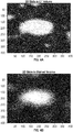
Fig. 6 is an illustration of a resulting reflection image, without noise, of a lesion; -
Fig. 7 is an illustration of a polar image of the resulting reflection image ofFig. 6 in polar coordinates with random points displayed thereon; -
Fig. 8 is an illustration of a model kernel representing what is seen in an isolated reflection; -
Fig. 9 is an illustration of a resulting image with the kernel randomly pasted in polar coordinates; -
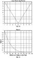
Fig. 10 is a linear structuring element chart for performing linear closings (where close peaks have been connected) for twenty different directions between 0 and 180 degrees to simulate apparent blurring in real ultrasound images around high density points; -
Fig. 11 is a difference of radius to the peak chart representing the radius difference to the peak ("radiusDif") for each pixel along a profile for adding comet tails, as used in the formulas described herein; -
Fig. 12 is a difference of angle to the peak chart representing the angle difference to the peak ("angleDif") for each pixel along a profile for adding comet tails, as used in the formulas described herein; -
Fig. 13 is a resulting image after performing closings according to the linear structuring element chart ofFig. 10 ; -
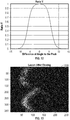
Fig. 14 is a resulting image after adding comet tails according to the difference of radius to the peak chart ofFig. 11 and the difference of angle to peak chart ofFig. 12 ; -
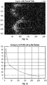
Fig. 15 is a chart showing the background profile along the radius; -
Fig. 16 is an illustration of an initial background image after the profile ofFig. 15 is copied on each row of the background image; -
Fig. 17 is an illustration of a merged image where the initial background image ofFig. 16 is merged with the image of the lesion; -
Fig. 18 is an illustration of the merged image with random locations for noise in the background simulated thereon; -
Fig. 19 is an illustration of a model kernel of a noise point; -
Fig. 20 is an illustration of a resulting image after noise is added in the background; -
Fig. 21 is a chart for defining the ratio for applying a shadow effect; -
Fig. 22 is the resulting image after the shadow effect is applied; -
Fig. 23 is the resulting virtual radial EBUS image after transforming the coordinates to Cartesian; and -
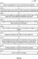
Fig. 24 is a flow chart of a method of performing a surgical navigation procedure using the system ofFig. 1 . - The present disclosure is directed to a system and method for constructing virtual radial probe endobronchial ultrasound ("radial EBUS") images from CT data, registering the virtual radial EBUS images with CT data or real time ultrasound images (radial or linear), and performing a surgical navigation procedure using the virtual radial EBUS images and CT data. The constructed virtual radial EBUS images utilize the creation of noise similar to real noise to create a more accurate and more realistic simulation of the images. The constructed virtual radial EBUS images may be formed as a composite image with elements extracted from the CT data combined therewith. The constructed virtual radial EBUS images may be used for guidance, training, navigation planning, improved navigation accuracy, navigation confirmation, and treatment confirmation.
- As described in greater detail below, the disclosed system and methods model background noise and various types of artifacts in order to be as realistic as possible, finding an underlying probabilistic model to real ultrasound films, reverse engineering from true data. In the methods disclosed herein, as with real images, the noise gets rougher as the distance from the center increases. In order to get a realistic simulation using this approach, most computations are performed in polar coordinates and the result is converted to Cartesian.
-
Fig. 1 depicts an Electromagnetic Navigation (EMN)system 100 configured for reviewing CT image data to identify one or more targets, planning a pathway to an identified target (planning phase), navigating an extended working channel (EWC) 12 of a catheter assembly to a target (navigation phase) via a user interface, and confirming placement of theEWC 12 relative to the target. One such EMN system is the ELECTROMAGNETIC NAVIGATION BRONCHOSCOPY® system currently sold by Medtronic PLC. The target may be tissue of interest, or correlate to a position of interest, identified by review of the CT image data during the planning phase. Following navigation, a medical instrument, such as a biopsy tool or other tool, may be inserted into theEWC 12 to obtain a tissue sample from the tissue located at, or proximate to, the target or to treat tissue at, or proximate to, the target. -
EMN system 100 generally includes an operating table 20 configured to support a patient "P," abronchoscope 30 configured for insertion through the patient's "P's" mouth into the patient's "P's" airways; monitoringequipment 120 coupled to bronchoscope 30 (e.g., a video display, for displaying the video images received from the video imaging system of bronchoscope 30); atracking system 50 including atracking module 52, a plurality ofreference sensors 54 and atransmitter mat 56; and acomputing device 125 including software and/or hardware used to facilitate identification of a target, pathway planning to the target, navigation of a medical instrument to the target, and confirmation of placement of anEWC 12, or a suitable device therethrough, relative to the target. -
Computing device 125 may be any suitable computing device including a processor and storage medium, wherein the processor is capable of executing instructions stored on the storage medium. Thecomputing device 125 may further include a database configured to store patient data, CT data sets including CT images, fluoroscopic data sets including fluoroscopic images and video, ultrasonic images or data sets, navigation plans, and any other such data. Although not explicitly illustrated, thecomputing device 125 may include inputs, or may otherwise be configured to receive, CT data sets, fluoroscopic images/video, ultrasonic images/video and other data described herein. Additionally,computing device 125 includes a display configured to display graphical user interfaces.Computing device 125 may be connected to one or more networks through which one or more databases may be accessed and may be configured to perform any of the methods described herein. - As described in further detail below,
computing device 125 is configured to create virtual radial EBUS images CT data. The virtual radial EBUS images may be displayed by computingdevice 125 for enhanced navigation to a target. Further,computing device 125 may also be configured to register the virtual radial EBUS images with real time radial EBUS images acquired byultrasonic imaging device 45. The registration between the two data sets may be accomplished via image analysis and comparison between the two data sets. Additionally, components of the CT data set may be extracted therefrom and integrated into either or both of the real time ultrasound images received from the radial EBUS probe or the virtual radial EBUS images constructed from the CT data set. - Having briefly described the components of
system 100 depicted inFig. 1 , the following description ofFigs. 2-23 provides an exemplary workflow of creating a virtual ultrasonic image, in particular, virtual radial EBUS images, using the components ofsystem 100, and will be described generally asmethod 200. Any of the methods described herein may be carried out by any component ofsystem 100 and may include all or some of the steps described. Additionally, any of the methods may be carried out in any order, specifically, in a different order of the steps described and illustrated in the figures. -
Method 200 begins atstep 201 wherecomputing device 125 receives preoperative CT data of a patient's branched luminal network. Instep 203,computing device 125 calculates a gradient, for example a 3D Sobel gradient, of the CT data (Fig. 3 ). Instep 205,computing device 125 obtains 2D slices of the CT data by interpolation in 3D (Fig. 3 ). Instep 207,computing device 125 calculates transmission and reflection values on each radial line away from a center of each 2D slice to create a lesion image (Fig. 5 ). Instep 209,computing device 125 converts the lesion image to a polar lesion image (Fig. 7 ). Instep 211,computing device 125 generates random noise in the polar lesion image (Fig. 9 ). Instep 213,computing device 125 adds random comet tails to the polar lesion image based on the random noise (Fig. 14 ). Instep 215,computing device 125 creates a background image (Fig. 16 ) by computing the mean profile along the radius from a series of polar lesion images. Instep 217,computing device 125 merges the background image with the polar lesion image to create a merged image (Fig. 17 ). Instep 219,computing device 125 generates random noise in the background of the merged image (Figs. 18-20 ). Instep 221,computing device 125 simulates density variations in the merged image (Figs. 21-23 ). Instep 223,computing device 125 transforms the coordinates of the merged image to Cartesian to construct a virtual radial ultrasound image (Fig. 23 ). - With respect to
Fig. 3 andsteps method 200, for the physical model, a 3D Sobel gradient with 2 pixels of step is used, however, it is understood that any gradient operator may be used. (uxl,uyl,uzl) is the 3D referential of the 3D volume considered (CT or gradient 300). (ux2,uy2,uz2) is the 3D referential of the ultrasound image, where uz2 is the direction of the probe. For eachultrasound image 301, uz2 is computed from thetrajectory 303. ux2 is computed using the following formula:

- It is assumed that the y axis of the ultrasound is vertical (constant roll), which is not true and will be addressed in a later step. uy2 is computed using the following formula:

- Each point in the 2D cutting slice is defined relatively, to ux2 and uy2, so non-integer values are obtained in the 3D referential (ux2,uy2,uz2) and the 3D coordinates are derived in (uxl,uyl,uzl). Trilinear interpolation is performed between the eight neighbors (with integer coordinates).
- A blurred volume is used instead of the CT volume to avoid singularities in the steps that follow when dividing the gradient by zero values. The data is blurred with a mask, for example a Sobel mask. In particular,
Fig. 4A illustrates a 2D slice obtained from the CT volume before blurring andFig. 4B illustrates a 2D slice of the blurred volume.Figs. 4A and4C illustrates the 3D gradient along the X axis and the Y axis, respectively. - With respect to step 207 of
method 200, the transmission and reflection for creating the virtual radial EBUS image will now be described with reference toFig. 5 . Two 2D images are defined, imVirt and imTransmit. imVirt is the result image which contains the reflected signal. imTransmit contains the transmitted data and is a temporary image. Two loops are performed, an external loop and an internal loop. The external loop is performed along an angle, scanning the border points of the image ptBor. The internal loop is performed by scanning the points on theline 505 joining the central point ptCen to the border point ptBor, starting on the perimeter of thecentral disk 507. The unit vector Rad ofline 505 is computed in 3D. The current point ptCur and the previous point ptPrev online 505 are computed. valTransmit is defined as thevalue 1 on the perimeter ofcentral disk 507. The following formulas for reflection and transmission at ptCur are applied (seeFig. 5 ):

which is the product of: the cosines of the incident angle, with the squared relative density attenuation, and with the incoming signal; and

which is the non-reflected signal. For expediency, each value of imVirt can be computed for only a single angle. The resultingreflection image 601 is illustrated inFig. 6 , with an opening or hole 603 in the contour, representing the portion of a lesion connected to a blood vessel. - As described in further detail below, the disclosed methods model background noise and various types of artifacts in order to form a simulated ultrasound image that is as realistic, and as close to a real ultrasound image, as possible. The disclosed methods find an underlying probabilistic model to real ultrasound films, reverse engineering from true data. In the methods disclosed herein, as with real images, the noise gets rougher, or more exaggerated, as the distance from the center increases. In order to get a realistic simulation using this approach, most computations are performed in polar coordinates.
- The reflection image 601 (
Fig. 6 ) is shown as apolar image 701 inFig. 7 after the lesion image is converted to a polar image instep 209 ofmethod 200. With respect to step 211 ofmethod 200, random points (for example, five hundred random points) are defined as represented by points 703 (e.g., 703...n) inFig. 7 . A model kernel 801 (Fig. 8 ) is defined from several hundred sample peaks in lesions from real ultrasound images. Themodel kernel 801 represents what is seen in isolated reflection. For larger regions of reflection, the peaks interact. For each random peak, the kernel in the image of lesions is copied, with the amplitude defined by the gray value in the image of reflection at the location of the peak. In the formula below, neiY and neiX are lists of coordinates in the neighborhood of peakX and peakY:
- The resulting image of lesions is illustrated in
Fig. 9 asimage 901, where relevant gray values are obtained by multiplying by 6,000. That is, the image imLesion is scaled, multiplied by 6,000, to get values of similar scope as in real ultrasound images. - To simulate the apparent blurring in real ultrasound images around high density points, a plurality, for example twenty, grey linear morphological closings are performed for a plurality, for example twenty, different directions between 0 and 180 degrees (see
Fig. 10 , the linear structuring element used). The use of a non-flat structuring element provides a reduced grey level between two peaks to be visually joined by a segment. The resulting image is illustrated inFig. 13 asimage 1301. Additionally, the artifacts of comet tails are added to a peak if it belongs to the 10% highest peaks in the image (taking into account all peaks including those in black regions), and randomly in 10% of these cases, resulting in theimage 1401 illustrated inFig. 14 showing a lesion with comet tails. To add a comment peak, each of the peak's neighbors neiPeak, above and below, is considered inside the kernel mask. We copy to the right of the neighbor along a horizontal line a decreasing profile defined for each pixel as:

where radiusDif is the radius difference to the peak and angleDif is the angle difference, for each pixel along the profile (seeFig. 11 andFig. 12 ). - With respect to step 215 of
method 200, the mean profile is computed along the radius from a series of images. It is composed from constant values, partly approximated as a decreasing exponential (seeFig. 15 ). This profile is copied on each row of the background image (seeFig. 14 ) and aninitial background image 1601 is created (Fig. 16 ). With respect to step 217 ofmethod 200, the background and lesion images are merged according to the heuristic formula:
which means that the amplitude of the lesion on the background decreases linearly with the radius (the background is a decreasing exponential). The resultingmerged image 1701 is shown inFig. 17 afterstep 217 ofmethod 200 is performed by computingdevice 125. - With respect to step 219 of
method 200, random noise is simulated in the background by: 1) generating 40,000 random points (seeFig. 18 ); 2) defining a kernel of "noise point" from statistics measures in a series of images (seeFig. 19 ); and3 ) applying the following formula for each random point:
where ly and lx are the neighboring rows and columns of the random point inside the kernel. The resultingimage 2001 is shown inFig. 20 after completion ofstep 219 ofmethod 200 by computingdevice 125. Considering the number of points, the pasted kernels interact and produce random shapes. - With respect to step 221 of
method 200, to simulate the density variations of low frequency according to the angle, the following steps are taken. First, three random values V1, V2, V3 are computed in a fixed range (around 1). Second, the polynomial polShadow(angle) ofdegree 3 defined at the angles [0, 120, 240, 360] by the values [V1, V2, V3,V1] are computed. Third, a 2D ratio(radius,angle) (seeFig. 21 ) is defined where: - Ratio(minRadius,angle) = 1;
- Ratio(maxRadius,angle) = polShadow(angle); and
- Ratio(radius, angle) is linear between minRadius and maxRadius.
- Fourth, the image is multiplied by Ratio(radius,angle) ^ 3 and the
image 2201 shown inFig. 22 is obtained. Lastly, instep 223 ofmethod 200, the coordinates are transformed to Cartesian to obtain the virtualradial EBUS image 2301 shown inFig. 23 . - Having described the construction of the virtual radial EBUS image above with respect to
method 200 andFigs. 2-23 , a method of performing a surgical navigationprocedure using system 100 will now be described asmethod 2400, with specific reference toFig. 1 andFig. 24 . - As shown in
Fig. 1 ,EWC 12 is part of acatheter guide assembly 40. In practice, theEWC 12 is inserted intobronchoscope 30 for access to a luminal network of the patient "P." Specifically,EWC 12 ofcatheter guide assembly 40 may be inserted into a working channel ofbronchoscope 30 for navigation through a patient's luminal network. A locatable guide (LG) 32, including asensor 44 is inserted into theEWC 12 and locked into position such that thesensor 44 extends a desired distance beyond the distal tip of theEWC 12. The position and orientation of thesensor 44 relative to the reference coordinate system, and thus the distal portion of theEWC 12, within an electromagnetic field can be derived.Catheter guide assemblies 40 are currently marketed and sold by Medtronic PLC under the brand names SUPERDIMENSION® Procedure Kits, or EDGE™ Procedure Kits, and are contemplated as useable with the present disclosure. For a more detailed description of thecatheter guide assemblies 40, reference is made to commonly-owned U.S. Patent No.U.S. 9,247,992, filed on March 15, 2013, by Ladtkow et al U.S. Patent No. 7,233,820 , andU.S. Patent No. 9,044,254 - An
ultrasonic imaging device 45 capable of acquiring ultrasonic images or video of the patient "P" is also included in this particular aspect ofsystem 100. The images, series of images, or video captured by theultrasonic imaging device 45 may be stored within theultrasonic imaging device 45 or transmitted tocomputing device 125 for storage, processing, registration with other data sets, and display. Additionally, theultrasonic imaging device 45 may be a radial EBUS probe that can be inserted through a working channel of thebronchoscope 40 or more specifically, through theEWC 12 ofcatheter guide assembly 40 for navigation to peripheral regions of a luminal network. - With respect to the planning phase,
computing device 125 utilizes previously acquired CT image data for generating and viewing a three dimensional model of the patient's "P's" airways, enables the identification of a target on the three dimensional model (automatically, semi-automatically, or manually), and allows for determining a pathway through the patient's "P's" airways to tissue located at and around the target. More specifically, CT images acquired from previous CT scans are processed and assembled into a three dimensional CT volume, which is then utilized to generate a three dimensional model of the patient's "P's" airways. The three dimensional model may be displayed on a display associated withcomputing device 125, or in any other suitable fashion. Usingcomputing device 125, various views of the three dimensional model or enhanced two dimensional images generated from the three dimensional model are presented. The enhanced two dimensional images may possess some three dimensional capabilities because they are generated from three dimensional data. The three dimensional model may be manipulated to facilitate identification of target on the three dimensional model or two dimensional images, and selection of a suitable pathway through the patient's "P's" airways to access tissue located at the target can be made. Once selected, the pathway plan, three dimensional model, and images derived therefrom, can be saved and exported to a navigation system for use during the navigation phase(s). One such planning software is the ILOGIC® planning suite currently sold by Medtronic PLC. - With respect to the navigation phase, a six degrees-of-freedom
electromagnetic tracking system 50, e.g., similar to those disclosed inU.S. Patent Nos. 8,467,589 ,6,188,355 , and publishedPCT Application Nos. WO 00/10456 WO 01/67035 Tracking system 50 includes atracking module 52, a plurality ofreference sensors 54, and atransmitter mat 56.Tracking system 50 is configured for use with alocatable guide 32, particularlysensor 44, andultrasonic imaging device 45. As described above,locatable guide 32 andsensor 44 are configured for insertion through anEWC 12 into a patient's "P's" airways (either with or without bronchoscope 30) and are selectively lockable relative to one another via a locking mechanism. -
Transmitter mat 56 is positioned beneath patient "P."Transmitter mat 56 generates an electromagnetic field around at least a portion of the patient "P" within which the position of a plurality ofreference sensors 54 and thesensor element 44 can be determined with use of atracking module 52. One or more ofreference sensors 54 are attached to the chest of the patient "P." The six degrees of freedom coordinates ofreference sensors 54 are sent to computing device 125 (which includes the appropriate software) where they are used to calculate a patient coordinate frame of reference. Registration, as detailed below, is generally performed to coordinate locations of the three dimensional model and two dimensional images from the planning phase with the patient's "P's" airways as observed through thebronchoscope 30, and allow for the navigation phase to be undertaken with precise knowledge of the location of thesensor 44 andultrasonic imaging device 45, even in portions of the airway where thebronchoscope 30 cannot reach. Further details of such a registration technique and their implementation in luminal navigation can be found inU.S. Patent Application Pub. No. 2011/0085720 , the entire content of which is incorporated herein by reference, although other suitable techniques are also contemplated. - Registration of the patient's "P's" location on the
transmitter mat 56 is performed by movingLG 32 through the airways of the patient's "P." More specifically, data pertaining to locations ofsensor 44, whilelocatable guide 32 is moving through the airways, is recorded usingtransmitter mat 56,reference sensors 54, and trackingmodule 52. A shape resulting from this location data is compared to an interior geometry of passages of the three dimensional model generated in the planning phase, and a location correlation between the shape and the three dimensional model based on the comparison is determined, e.g., utilizing the software oncomputing device 125. In addition, the software identifies non-tissue space (e.g., air filled cavities) in the three dimensional model. The software aligns, or registers, an image representing a location ofsensor 44 with a the three dimensional model and two dimensional images generated from the three dimension model, which are based on the recorded location data and an assumption thatlocatable guide 32 remains located in non-tissue space in the patient's "P's" airways. Alternatively, a manual registration technique may be employed by navigating thebronchoscope 30 with thesensor 44 to pre-specified locations in the lungs of the patient "P", and manually correlating the images from the bronchoscope to the model data of the three dimensional model. - Following registration of the patient "P" to the image data and pathway plan, a user interface is displayed in the navigation software which sets for the pathway that the clinician is to follow to reach the target. One such navigation software is the ILOGIC® navigation suite currently sold by Medtronic PLC.
- Once
EWC 12 has been successfully navigated proximate the target as depicted on the user interface, thelocatable guide 32 may be unlocked fromEWC 12 and removed, leavingEWC 12 in place as a guide channel for guiding medical instruments including without limitation, optical systems, ultrasound probes such asultrasonic imaging device 45, marker placement tools, biopsy tools, ablation tools (i.e., microwave ablation devices), laser probes, cryogenic probes, sensor probes, and aspirating needles to the target. -
Method 2400 begins atstep 2401 where preoperative CT data of a patient's branched luminal network is received. Instep 2403, the 3D model of the branched luminal network is generated and the navigation plan and route to one or more targets is generated. Instep 2405, the virtual radial EBUS images are constructed, for example, bymethod 200 described above (Figs. 2-23 ). Instep 2405, each virtual radial EBUS image has assumed position coordinates, which may be extracted from the CT data. Instep 2407, a radial EBUS probe is navigated using the navigation plan generated instep 2403. During navigation of the radial EBUS probe instep 2407, the radial EBUS probe is acquiring radial EBUS images of the patient's branched luminal network. Instep 2409, the electromagnetic (EM) position of the radial EBUS probe is tracked and the position of the radial EBUS probe is displayed on a display. - In
step 2411, the virtual radial EBUS images (constructed in step 2405) are registered to the real radial EBUS images (acquired by radial EBUS probe in step 2407). This registration instep 2411 may be accomplished, for example, by image-based analysis. Alternatively, or in addition, the registration instep 2411 may be accomplished by location-based analysis, where the assumed coordinates of the virtual radial EBUS images are compared to the actual coordinates of the real radial EBUS images. In one aspect,step 2411 includes utilizing registration techniques including both image-based and location-based analysis. - In
step 2413, the displayed position of the radial EBUS probe is confirmed or updated on the display, based on the registration instep 2411 and a comparison of the assumed coordinates of the virtual radial EBUS images and the tracked EM position data of the radial EBUS probe. Instep 2415, the navigation procedure is continued until the target is reached and instep 2417, a treatment (e.g., biopsy) is performed at the target. In order to better visualize the branched luminal network and the target, portions of the CT data may be extracted and overlaid onto the virtual radial EBUS images. - From the foregoing and with reference to the various figure drawings, those skilled in the art will appreciate that certain modifications can also be made to the present disclosure without departing from the scope of the same. For example, although the systems and methods are described as usable with an EMN system for navigation through a luminal network such as the lungs, the systems and methods described herein may be utilized with systems that utilize other navigation and treatment devices such as percutaneous devices. Additionally, although the above-described system and method is described as used within a patient's luminal network, it is appreciated that the above-described systems and methods may be utilized in other target regions such as the liver. Further, the above-described systems and methods are also usable for transthoracic needle aspiration procedures.
- Detailed embodiments of the present disclosure are disclosed herein. However, the disclosed embodiments are merely examples of the disclosure, which may be embodied in various forms and aspects. Therefore, specific structural and functional details disclosed herein are not to be interpreted as limiting, but merely as a basis for the claims and as a representative basis for teaching one skilled in the art to variously employ the present disclosure in virtually any appropriately detailed structure.
- As can be appreciated a medical instrument such as a biopsy tool or an energy device, such as a microwave ablation catheter, that is positionable through one or more branched luminal networks of a patient to treat tissue may prove useful in the surgical arena and the present disclosure is directed to systems and methods that are usable with such instruments and tools. Access to luminal networks may be percutaneous or through natural orifice using navigation techniques. Additionally, navigation through a luminal network may be accomplished using image-guidance. These image-guidance systems may be separate or integrated with the energy device or a separate access tool and may include MRI, CT, fluoroscopy, ultrasound, electrical impedance tomography, optical, and/or device tracking systems. Methodologies for locating the access tool include EM, IR, echolocation, optical, and others. Tracking systems may be integrated to an imaging device, where tracking is done in virtual space or fused with preoperative or live images. In some cases the treatment target may be directly accessed from within the lumen, such as for the treatment of the endobronchial wall for COPD, Asthma, lung cancer, etc. In other cases, the energy device and/or an additional access tool may be required to pierce the lumen and extend into other tissues to reach the target, such as for the treatment of disease within the parenchyma. Final localization and confirmation of energy device or tool placement may be performed with imaging and/or navigational guidance using a standard fluoroscopic imaging device incorporated with methods and systems described above.
- While several embodiments of the disclosure have been shown in the drawings, it is not intended that the disclosure be limited thereto, as it is intended that the disclosure be as broad in scope as the art will allow and that the specification be read likewise. Therefore, the above description should not be construed as limiting, but merely as exemplifications of particular embodiments. Those skilled in the art will envision other modifications within the scope and spirit of the claims appended hereto.
- The invention may be described by reference to the following numbered paragraphs:-
- 1. A method for constructing virtual radial ultrasonic images from CT data, the method comprising:
- receiving preoperative CT data of a branched luminal network;
- calculating a gradient of the CT data;
- obtaining 2D slices of the CT data by interpolation in 3D;
- calculating transmission and reflection values on radial lines away from a center of each 2D slice to create a lesion image;
- converting the lesion image to a polar lesion image;
- generating random noise in the polar lesion image;
- adding random comet tails to the polar lesion image based on the random noise;
- creating a background image by computing a mean profile along a radius from a series of polar lesion images;
- merging the background image with the polar lesion image to create a merged image;
- generating random noise in a background of the merged image;
- simulating density variations in the merged image; and
- transforming coordinates of the merged image to Cartesian to construct a virtual radial ultrasound image.
- 2. The method according to
paragraph 1, wherein calculating transmission and reflection values on each radial line away from a center of each 2D slice to create a lesion image includes applying the formulas:

- 3. The method according to
paragraph 1, further comprising copying a kernel in the polar lesion image using a model kernel representing what is seen in an isolated reflection. - 4. The method according to
paragraph 3, wherein copying a kernel in the polar lesion image using a model kernel representing what is seen in an isolated reflection includes applying the formula:
- 5. The method according to
paragraph 1, further comprising simulating blurring of real ultrasound images around high density points in the polar lesion image. - 6. The method according to
paragraph 1, wherein simulating blurring of real ultrasound images around high density points in the polar lesion image includes performing a plurality of grey linear closings for a plurality of directions between 0 and 180 degrees. - 7. The method according to
paragraph 1, wherein adding random comet tails to the polar lesion image based on the random noise includes adding a comet to a peak by considering each neighbor of the peak (neiPeak), above and below, in a kernel mask. - 8. The method according to
paragraph 7, further comprising copying to the right of each neighbor of the peak along a horizontal line a decreasing profile defined for each pixel as:
- 9. The method according to
paragraph 1, wherein merging the background image with the polar lesion image to create a merged image includes applying a heuristic formula. - 10. The method according to
paragraph 9, wherein the heuristic formula is:
- 11. A system for constructing virtual radial ultrasound images from CT data, comprising a computing device configured to:
- receive preoperative CT data of a branched luminal network;
- calculate a gradient of the CT data;
- obtain 2D slices of the CT data by interpolation in 3D;
- calculate transmission and reflection values on radial lines away from a center of each 2D slice to create a lesion image;
- convert the lesion image to a polar lesion image;
- generate random noise in the polar lesion image;
- add random comet tails to the polar lesion image based on the random noise;
- create a background image by computing a mean profile along a radius from a series of polar lesion images;
- merge the background image with the polar lesion image to create a merged image;
- generate random noise in a background of the merged image;
- simulate density variations in the merged image; and
- transform coordinates of the merged image to Cartesian to construct a virtual radial ultrasound image.
- 12. The system according to
paragraph 11, wherein the computing device is configured to calculate transmission and reflection values on each radial line away from a center of each 2D slice to create a lesion image by applying the formulas:

- 13. The system according to
paragraph 11, wherein the computing device is further configured to copy a kernel in the polar lesion image using a model kernel representing what is seen in an isolated reflection. - 14. The system according to paragraph 13, wherein the computing device is configured to copy a kernel in the polar lesion image using a model kernel representing what is seen in an isolated reflection by applying the formula:

- 15. The system according to
paragraph 11, wherein the computing device is further configured to simulate blurring of real ultrasound images around high density points in the polar lesion image. - 16. The system according to
paragraph 11, wherein the computing device is configured to simulate blurring of real ultrasound images around high density points in the polar lesion image by performing a plurality of grey linear closings for a plurality of directions between 0 and 180 degrees. - 17. The system according to
paragraph 11, wherein the computing device is configured to add random comet tails to the polar lesion image based on the random noise by adding a comet to a peak by considering each neighbor of the peak (neiPeak), above and below, in a kernel mask. - 18. The system according to paragraph 17, wherein the computing device is further configured to copy to the right of each neighbor of the peak along a horizontal line a decreasing profile defined for each pixel as:

- 19. The system according to
paragraph 11, wherein the computing device is configured to merge the background image with the polar lesion image to create a merged image by applying a heuristic formula. - 20. The system according to paragraph 19, wherein the heuristic formula is:

Claims (14)
- A method for constructing virtual radial ultrasonic images from CT data, the method comprising:receiving preoperative CT data of a branched luminal network;calculating a gradient of the CT data;obtaining 2D slices of the CT data by interpolation in 3D;calculating transmission and reflection values on radial lines away from a center of each 2D slice to create a lesion image;converting the lesion image to a polar lesion image;generating random noise in the polar lesion image;adding random comet tails to the polar lesion image based on the random noise;creating a background image by computing a mean profile along a radius from a series of polar lesion images;merging the background image with the polar lesion image to create a merged image;generating random noise in a background of the merged image;
simulating density variations in the merged image; andtransforming coordinates of the merged image to Cartesian to construct a virtual radial ultrasound image. - The method according to claim 1, wherein calculating transmission and reflection values on each radial line away from a center of each 2D slice to create a lesion image includes applying the formulas:


- The method according to claim 1, further comprising copying a kernel in the polar lesion image using a model kernel representing what is seen in an isolated reflection; preferably wherein copying a kernel in the polar lesion image using a model kernel representing what is seen in an isolated reflection includes applying the formula:

- The method according to any preceding claim, further comprising simulating blurring of real ultrasound images around high density points in the polar lesion image; and/or wherein simulating blurring of real ultrasound images around high density points in the polar lesion image includes performing a plurality of grey linear closings for a plurality of directions between 0 and 180 degrees.
- The method according to any preceding claim, wherein adding random comet tails to the polar lesion image based on the random noise includes adding a comet to a peak by considering each neighbor of the peak (neiPeak), above and below, in a kernel mask; preferably further comprising copying to the right of each neighbor of the peak along a horizontal line a decreasing profile defined for each pixel as:

- The method according to any preceding claim, wherein merging the background image with the polar lesion image to create a merged image includes applying a heuristic formula; preferably wherein the heuristic formula is:

- A system for constructing virtual radial ultrasound images from CT data, comprising a computing device configured to:receive preoperative CT data of a branched luminal network;calculate a gradient of the CT data;obtain 2D slices of the CT data by interpolation in 3D;calculate transmission and reflection values on radial lines away from a center of each 2D slice to create a lesion image;convert the lesion image to a polar lesion image;generate random noise in the polar lesion image;add random comet tails to the polar lesion image based on the random noise;create a background image by computing a mean profile along a radius from a series of polar lesion images;merge the background image with the polar lesion image to create a merged image;generate random noise in a background of the merged image;
simulate density variations in the merged image; andtransform coordinates of the merged image to Cartesian to construct a virtual radial ultrasound image. - The system according to claim 7, wherein the computing device is configured to calculate transmission and reflection values on each radial line away from a center of each 2D slice to create a lesion image by applying the formulas:


- The system according to claim 7 or claim 8, wherein the computing device is further configured to copy a kernel in the polar lesion image using a model kernel representing what is seen in an isolated reflection; preferably wherein the computing device is configured to copy a kernel in the polar lesion image using a model kernel representing what is seen in an isolated reflection by applying the formula:

- The system according to any of claims 7 to 9, wherein the computing device is further configured to simulate blurring of real ultrasound images around high density points in the polar lesion image.
- The system according to any of claims 7 to 10, wherein the computing device is configured to simulate blurring of real ultrasound images around high density points in the polar lesion image by performing a plurality of grey linear closings for a plurality of directions between 0 and 180 degrees.
- The system according to any of claims 7 to 11, wherein the computing device is configured to add random comet tails to the polar lesion image based on the random noise by adding a comet to a peak by considering each neighbor of the peak (neiPeak), above and below, in a kernel mask; preferably wherein the computing device is further configured to copy to the right of each neighbor of the peak along a horizontal line a decreasing profile defined for each pixel as:

- The system according to any of claims 7 to 12, wherein the computing device is configured to merge the background image with the polar lesion image to create a merged image by applying a heuristic formula.
- The system according to claim 13, wherein the heuristic formula is:

Applications Claiming Priority (2)
| Application Number | Priority Date | Filing Date | Title |
|---|---|---|---|
| US201862665667P | 2018-05-02 | 2018-05-02 | |
| US16/383,888 US10872449B2 (en) | 2018-05-02 | 2019-04-15 | System and method for constructing virtual radial ultrasound images from CT data and performing a surgical navigation procedure using virtual ultrasound images |
Publications (2)
| Publication Number | Publication Date |
|---|---|
| EP3566652A1 true EP3566652A1 (en) | 2019-11-13 |
| EP3566652B1 EP3566652B1 (en) | 2022-10-26 |
Family
ID=66349460
Family Applications (1)
| Application Number | Title | Priority Date | Filing Date |
|---|---|---|---|
| EP19172131.5A Active EP3566652B1 (en) | 2018-05-02 | 2019-05-01 | System and method for constructing virtual radial ultrasound images from ct data and performing a surgical navigation procedure using virtual ultrasound images |
Country Status (4)
| Country | Link |
|---|---|
| US (2) | US10872449B2 (en) |
| EP (1) | EP3566652B1 (en) |
| CN (1) | CN110432986B (en) |
| AU (1) | AU2019202779B1 (en) |
Families Citing this family (10)
| Publication number | Priority date | Publication date | Assignee | Title |
|---|---|---|---|---|
| JP7483361B2 (en) * | 2019-12-06 | 2024-05-15 | キヤノンメディカルシステムズ株式会社 | Medical image processing device, medical image diagnostic device, and medical image processing program |
| JP7651576B2 (en) * | 2019-12-19 | 2025-03-26 | ノア メディカル コーポレーション | Systems and methods for robotic bronchoscopy navigation |
| US11446095B2 (en) | 2019-12-24 | 2022-09-20 | Biosense Webster (Israel) Ltd. | 2D pathfinder visualization |
| CN112043377B (en) * | 2020-10-12 | 2022-05-10 | 中国人民解放军总医院第五医学中心 | Method and system for ablation path planning assisted by ultrasound field simulation in any CT slice |
| US12076099B2 (en) * | 2021-07-06 | 2024-09-03 | Verb Surgical Inc. | Projection operator for inverse kinematics of a surgical robot for low degree of freedom tools |
| CN113413213B (en) * | 2021-07-14 | 2023-03-14 | 广州医科大学附属第一医院(广州呼吸中心) | CT result processing method, navigation processing method, device and detection system |
| US12591986B2 (en) * | 2021-11-18 | 2026-03-31 | Remex Medical Corp. | Method and navigation system for registering two-dimensional image data set with three-dimensional image data set of body of interest |
| EP4531743A4 (en) * | 2022-05-31 | 2026-05-20 | Noah Medical Corp | SYSTEMS AND METHODS FOR A ROBOT ENDOSCOPE WITH INTEGRATED TOOL-IN-LESION TOMOSYNTHESE |
| WO2024004597A1 (en) * | 2022-06-29 | 2024-01-04 | 富士フイルム株式会社 | Learning device, trained model, medical diagnosis device, endoscopic ultrasonography device, learning method, and program |
| CN116196031B (en) * | 2022-11-29 | 2026-03-20 | 上海市胸科医院 | A method, apparatus, device, and storage medium for generating virtual ultrasound images. |
Citations (7)
| Publication number | Priority date | Publication date | Assignee | Title |
|---|---|---|---|---|
| WO2000010456A1 (en) | 1998-08-02 | 2000-03-02 | Super Dimension Ltd. | Intrabody navigation system for medical applications |
| US6188355B1 (en) | 1997-12-12 | 2001-02-13 | Super Dimension Ltd. | Wireless six-degree-of-freedom locator |
| WO2001067035A1 (en) | 2000-03-09 | 2001-09-13 | Super Dimension Ltd. | Object tracking using a single sensor or a pair of sensors |
| US7233820B2 (en) | 2002-04-17 | 2007-06-19 | Superdimension Ltd. | Endoscope structures and techniques for navigating to a target in branched structure |
| US20110085720A1 (en) | 2009-05-14 | 2011-04-14 | Superdimension, Ltd. | Automatic Registration Technique |
| US8467589B2 (en) | 2008-06-06 | 2013-06-18 | Covidien Lp | Hybrid registration method |
| US9044254B2 (en) | 2012-08-07 | 2015-06-02 | Covidien Lp | Microwave ablation catheter and method of utilizing the same |
Family Cites Families (170)
| Publication number | Priority date | Publication date | Assignee | Title |
|---|---|---|---|---|
| US4202352A (en) | 1978-04-06 | 1980-05-13 | Research Development Corporation | Apparatus for measurement of expired gas concentration in infants |
| IL103445A (en) | 1991-10-18 | 1997-04-15 | Ethicon Inc | Endoscopic tissue manipulator |
| GB2329840C (en) | 1997-10-03 | 2007-10-05 | Johnson & Johnson Medical | Biopolymer sponge tubes |
| US6086586A (en) | 1998-09-14 | 2000-07-11 | Enable Medical Corporation | Bipolar tissue grasping apparatus and tissue welding method |
| US6468265B1 (en) | 1998-11-20 | 2002-10-22 | Intuitive Surgical, Inc. | Performing cardiac surgery without cardioplegia |
| US6659939B2 (en) | 1998-11-20 | 2003-12-09 | Intuitive Surgical, Inc. | Cooperative minimally invasive telesurgical system |
| US6459926B1 (en) | 1998-11-20 | 2002-10-01 | Intuitive Surgical, Inc. | Repositioning and reorientation of master/slave relationship in minimally invasive telesurgery |
| US8600551B2 (en) | 1998-11-20 | 2013-12-03 | Intuitive Surgical Operations, Inc. | Medical robotic system with operatively couplable simulator unit for surgeon training |
| US6398726B1 (en) | 1998-11-20 | 2002-06-04 | Intuitive Surgical, Inc. | Stabilizer for robotic beating-heart surgery |
| US6413981B1 (en) | 1999-08-12 | 2002-07-02 | Ortho-Mcneil Pharamceutical, Inc. | Bicyclic heterocyclic substituted phenyl oxazolidinone antibacterials, and related compositions and methods |
| US20050165276A1 (en) | 2004-01-28 | 2005-07-28 | Amir Belson | Methods and apparatus for accessing and treating regions of the body |
| US6656177B2 (en) | 2000-10-23 | 2003-12-02 | Csaba Truckai | Electrosurgical systems and techniques for sealing tissue |
| US6472372B1 (en) | 2000-12-06 | 2002-10-29 | Ortho-Mcneil Pharmaceuticals, Inc. | 6-O-Carbamoyl ketolide antibacterials |
| US6533784B2 (en) | 2001-02-24 | 2003-03-18 | Csaba Truckai | Electrosurgical working end for transecting and sealing tissue |
| US6913579B2 (en) | 2001-05-01 | 2005-07-05 | Surgrx, Inc. | Electrosurgical working end and method for obtaining tissue samples for biopsy |
| US7607440B2 (en) | 2001-06-07 | 2009-10-27 | Intuitive Surgical, Inc. | Methods and apparatus for surgical planning |
| US6802843B2 (en) | 2001-09-13 | 2004-10-12 | Csaba Truckai | Electrosurgical working end with resistive gradient electrodes |
| US8298161B2 (en) | 2002-09-12 | 2012-10-30 | Intuitive Surgical Operations, Inc. | Shape-transferring cannula system and method of use |
| US9808597B2 (en) | 2002-09-12 | 2017-11-07 | Intuitive Surgical Operations, Inc. | Shape-transferring cannula system and method of use |
| US7947000B2 (en) | 2003-09-12 | 2011-05-24 | Intuitive Surgical Operations, Inc. | Cannula system for free-space navigation and method of use |
| US7333644B2 (en) * | 2003-03-11 | 2008-02-19 | Siemens Medical Solutions Usa, Inc. | Systems and methods for providing automatic 3D lesion segmentation and measurements |
| CA2449080A1 (en) * | 2003-11-13 | 2005-05-13 | Centre Hospitalier De L'universite De Montreal - Chum | Apparatus and method for intravascular ultrasound image segmentation: a fast-marching method |
| US8052636B2 (en) | 2004-03-05 | 2011-11-08 | Hansen Medical, Inc. | Robotic catheter system and methods |
| AU2005237517B2 (en) * | 2004-04-26 | 2011-01-20 | Claudia Ingrid Henschke | Medical imaging system for accurate measurement evaluation of changes in a target lesion |
| US20060235457A1 (en) | 2005-04-15 | 2006-10-19 | Amir Belson | Instruments having a rigidizable external working channel |
| EP1906858B1 (en) | 2005-07-01 | 2016-11-16 | Hansen Medical, Inc. | Robotic catheter system |
| US20070135803A1 (en) | 2005-09-14 | 2007-06-14 | Amir Belson | Methods and apparatus for performing transluminal and other procedures |
| US8190238B2 (en) | 2005-12-09 | 2012-05-29 | Hansen Medical, Inc. | Robotic catheter system and methods |
| US8517955B2 (en) | 2009-05-08 | 2013-08-27 | Broncus Medical Inc. | Tissue sampling devices, systems and methods |
| US8827948B2 (en) | 2010-09-17 | 2014-09-09 | Hansen Medical, Inc. | Steerable catheters |
| US8578810B2 (en) | 2011-02-14 | 2013-11-12 | Intuitive Surgical Operations, Inc. | Jointed link structures exhibiting preferential bending, and related methods |
| KR102222672B1 (en) | 2011-02-15 | 2021-03-05 | 인튜어티브 서지컬 오퍼레이션즈 인코포레이티드 | Systems for detecting clamping or firing failure |
| US9393017B2 (en) | 2011-02-15 | 2016-07-19 | Intuitive Surgical Operations, Inc. | Methods and systems for detecting staple cartridge misfire or failure |
| US9572481B2 (en) | 2011-05-13 | 2017-02-21 | Intuitive Surgical Operations, Inc. | Medical system with multiple operating modes for steering a medical instrument through linked body passages |
| CN116712655A (en) | 2011-10-14 | 2023-09-08 | 直观外科手术操作公司 | catheter system |
| US9452276B2 (en) | 2011-10-14 | 2016-09-27 | Intuitive Surgical Operations, Inc. | Catheter with removable vision probe |
| US9387048B2 (en) | 2011-10-14 | 2016-07-12 | Intuitive Surgical Operations, Inc. | Catheter sensor systems |
| US20130096385A1 (en) | 2011-10-14 | 2013-04-18 | Intuitive Surgical Operations, Inc. | Vision probe and catheter systems |
| US10238837B2 (en) | 2011-10-14 | 2019-03-26 | Intuitive Surgical Operations, Inc. | Catheters with control modes for interchangeable probes |
| EP2809249B1 (en) | 2012-02-03 | 2018-12-26 | Intuitive Surgical Operations, Inc. | Steerable flexible needle with embedded shape sensing |
| US20130317519A1 (en) | 2012-05-25 | 2013-11-28 | Hansen Medical, Inc. | Low friction instrument driver interface for robotic systems |
| CN107280671B (en) | 2012-08-14 | 2020-04-17 | 直观外科手术操作公司 | System and method for configuring components in minimally invasive instruments |
| US20140052018A1 (en) | 2012-08-15 | 2014-02-20 | Intuitive Surgical Operations, Inc. | Specimen removal bag and methods of using same |
| US11272845B2 (en) * | 2012-10-05 | 2022-03-15 | Philips Image Guided Therapy Corporation | System and method for instant and automatic border detection |
| US11172809B2 (en) | 2013-02-15 | 2021-11-16 | Intuitive Surgical Operations, Inc. | Vision probe with access port |
| WO2014132209A1 (en) * | 2013-02-28 | 2014-09-04 | Koninklijke Philips N.V. | Segmentation of large objects from multiple three-dimensional views |
| US9839481B2 (en) | 2013-03-07 | 2017-12-12 | Intuitive Surgical Operations, Inc. | Hybrid manual and robotic interventional instruments and methods of use |
| US10206747B2 (en) | 2013-05-15 | 2019-02-19 | Intuitive Surgical Operations, Inc. | Guide apparatus for delivery of a flexible instrument and methods of use |
| US9592095B2 (en) | 2013-05-16 | 2017-03-14 | Intuitive Surgical Operations, Inc. | Systems and methods for robotic medical system integration with external imaging |
| CN103295455B (en) | 2013-06-19 | 2016-04-13 | 北京理工大学 | Based on the ultrasonic training system of CT image simulation and location |
| US9980785B2 (en) | 2013-10-24 | 2018-05-29 | Auris Health, Inc. | Instrument device manipulator with surgical tool de-articulation |
| KR102313708B1 (en) | 2013-10-25 | 2021-10-19 | 인튜어티브 서지컬 오퍼레이션즈 인코포레이티드 | Flexible instrument with embedded actuation conduits |
| WO2015061674A1 (en) | 2013-10-25 | 2015-04-30 | Intuitive Surgical Operations, Inc. | Flexible instrument with grooved steerable tube |
| WO2015075558A2 (en) | 2013-11-25 | 2015-05-28 | Body Vision Medical Ltd. | Surgical devices and methods of use thereof |
| CN114366181B (en) | 2013-12-13 | 2024-08-02 | 直观外科手术操作公司 | Telescopic biopsy needle |
| US9993222B2 (en) | 2014-02-05 | 2018-06-12 | Intuitive Surgical Operations, Inc. | System and method for dynamic virtual collision objects |
| US10779803B2 (en) | 2014-04-02 | 2020-09-22 | Intuitive Surgical Operations, Inc. | Devices, systems, and methods using a steerable stylet and flexible needle |
| US9801630B2 (en) | 2014-06-10 | 2017-10-31 | Ethicon Llc | Methods and devices for reinforcing a staple line |
| US10206686B2 (en) | 2014-06-10 | 2019-02-19 | Ethicon Llc | Bronchus sealants and methods of sealing bronchial tubes |
| US10792464B2 (en) | 2014-07-01 | 2020-10-06 | Auris Health, Inc. | Tool and method for using surgical endoscope with spiral lumens |
| US20160270865A1 (en) | 2014-07-01 | 2016-09-22 | Auris Surgical Robotics, Inc. | Reusable catheter with disposable balloon attachment and tapered tip |
| US10413372B2 (en) | 2014-07-28 | 2019-09-17 | Intuitive Surgical Operations, Inc. | Guide apparatus for delivery of a flexible instrument and methods of use |
| CN107072521B (en) | 2014-08-14 | 2020-10-27 | 直观外科手术操作公司 | System and method for cleaning endoscopic instruments |
| WO2016028858A1 (en) | 2014-08-22 | 2016-02-25 | Intuitive Surgical Operations, Inc. | Systems and methods for adaptive input mapping |
| US11033296B2 (en) | 2014-08-23 | 2021-06-15 | Intuitive Surgical Operations, Inc. | Systems and methods for dynamic trajectory control |
| WO2016032902A1 (en) | 2014-08-25 | 2016-03-03 | Intuitive Surgical Operations, Inc. | Systems and methods for medical instrument force sensing |
| JP6667510B2 (en) | 2014-09-09 | 2020-03-18 | インテュイティブ サージカル オペレーションズ, インコーポレイテッド | Flexible medical instruments |
| JP6736544B2 (en) | 2014-09-09 | 2020-08-05 | インテュイティブ サージカル オペレーションズ, インコーポレイテッド | System with different flexible guides and tools |
| US10542868B2 (en) | 2014-09-10 | 2020-01-28 | Intuitive Surgical Operations, Inc. | Devices, systems, and methods using mating catheter tips and tools |
| US11273290B2 (en) | 2014-09-10 | 2022-03-15 | Intuitive Surgical Operations, Inc. | Flexible instrument with nested conduits |
| US9737371B2 (en) | 2014-09-30 | 2017-08-22 | Auris Surgical Robotics, Inc. | Configurable robotic surgical system with virtual rail and flexible endoscope |
| US10314463B2 (en) | 2014-10-24 | 2019-06-11 | Auris Health, Inc. | Automated endoscope calibration |
| CN107111684A (en) | 2014-11-13 | 2017-08-29 | 直观外科手术操作公司 | System and method for filtering localization data |
| US11033716B2 (en) | 2015-01-12 | 2021-06-15 | Intuitive Surgical Operations, Inc. | Devices, systems, and methods for anchoring actuation wires to a steerable instrument |
| US10213110B2 (en) * | 2015-01-27 | 2019-02-26 | Case Western Reserve University | Analysis of optical tomography (OCT) images |
| US20160324580A1 (en) * | 2015-03-23 | 2016-11-10 | Justin Esterberg | Systems and methods for assisted surgical navigation |
| US10245034B2 (en) | 2015-08-31 | 2019-04-02 | Ethicon Llc | Inducing tissue adhesions using surgical adjuncts and medicants |
| US10349938B2 (en) | 2015-08-31 | 2019-07-16 | Ethicon Llc | Surgical adjuncts with medicants affected by activator materials |
| US10172973B2 (en) | 2015-08-31 | 2019-01-08 | Ethicon Llc | Surgical adjuncts and medicants for promoting lung function |
| AU2016321332B2 (en) | 2015-09-09 | 2020-10-08 | Auris Health, Inc. | Instrument device manipulator for a surgical robotics system |
| AU2016323982A1 (en) | 2015-09-18 | 2018-04-12 | Auris Health, Inc. | Navigation of tubular networks |
| EP3367954B1 (en) | 2015-10-26 | 2020-05-27 | Neuwave Medical, Inc. | Apparatuses for securing a medical device and related methods thereof |
| US9949749B2 (en) | 2015-10-30 | 2018-04-24 | Auris Surgical Robotics, Inc. | Object capture with a basket |
| US10639108B2 (en) | 2015-10-30 | 2020-05-05 | Auris Health, Inc. | Process for percutaneous operations |
| US9955986B2 (en) | 2015-10-30 | 2018-05-01 | Auris Surgical Robotics, Inc. | Basket apparatus |
| AU2016343849B2 (en) | 2015-10-30 | 2021-08-19 | Auris Health, Inc. | Process for percutaneous operations |
| WO2017083129A1 (en) | 2015-11-13 | 2017-05-18 | Intuitive Surgical Operations, Inc. | Stapler anvil with compliant tip |
| US10258326B2 (en) | 2016-02-08 | 2019-04-16 | Ethicon, Inc. | Elastic tissue reinforcing fastener |
| US10702137B2 (en) | 2016-03-14 | 2020-07-07 | Intuitive Surgical Operations, Inc.. | Endoscopic instrument with compliant thermal interface |
| US20170274189A1 (en) | 2016-03-24 | 2017-09-28 | Ethicon, Inc. | Single lumen balloon delivery catheter with lumen bypass at balloon |
| EP3448297B1 (en) | 2016-04-29 | 2022-06-15 | Intuitive Surgical Operations, Inc. | Compliant mechanisms having inverted tool members |
| US10327635B2 (en) * | 2016-05-03 | 2019-06-25 | Oregon Health & Science University | Systems and methods to compensate for reflectance variation in OCT angiography |
| CN108135583B (en) | 2016-05-31 | 2022-07-15 | 直观外科手术操作公司 | Compliant Biopsy Needle System |
| KR20190015581A (en) | 2016-06-30 | 2019-02-13 | 인튜어티브 서지컬 오퍼레이션즈 인코포레이티드 | System and method for fault reaction mechanism of medical robotic system |
| CN114886484A (en) | 2016-06-30 | 2022-08-12 | 直观外科手术操作公司 | Systems and methods for steerable elongated devices |
| CN109310287B (en) | 2016-07-01 | 2023-01-03 | 直观外科手术操作公司 | Computer-aided medical system and control method thereof |
| CN109475721B (en) | 2016-07-08 | 2021-06-08 | 直观外科手术操作公司 | Guide device and method of use for conveying elongated equipment |
| US10729886B2 (en) | 2016-08-24 | 2020-08-04 | Intuitive Surgical Operations, Inc. | Axial support structure for a flexible elongate device |
| US10881385B2 (en) | 2016-09-13 | 2021-01-05 | Intuitive Surgical Operations, Inc. | Radial telescoping guide apparatus for delivery of a flexible instrument and methods of use |
| US11432836B2 (en) | 2016-09-14 | 2022-09-06 | Intuitive Surgical Operations, Inc. | Joint assemblies with cross-axis flexural pivots |
| US10682192B2 (en) | 2016-09-30 | 2020-06-16 | Intuitive Surgical Operations, Inc. | Variable-length guide apparatus for delivery of a flexible instrument and methods of use |
| US9931025B1 (en) | 2016-09-30 | 2018-04-03 | Auris Surgical Robotics, Inc. | Automated calibration of endoscopes with pull wires |
| AU2017339213A1 (en) | 2016-10-07 | 2019-05-02 | Body Vision Medical Ltd | Devices for use in interventional and surgical procedures and methods of use thereof |
| WO2018071573A1 (en) | 2016-10-12 | 2018-04-19 | Intuitive Surgical Operations, Inc. | Surgical puncture device insertion systems and related methods |
| US10543048B2 (en) | 2016-12-28 | 2020-01-28 | Auris Health, Inc. | Flexible instrument insertion using an adaptive insertion force threshold |
| US10244926B2 (en) | 2016-12-28 | 2019-04-02 | Auris Health, Inc. | Detecting endolumenal buckling of flexible instruments |
| EP3562423A1 (en) | 2016-12-28 | 2019-11-06 | Auris Health, Inc. | Apparatus for flexible instrument insertion |
| WO2018132386A1 (en) | 2017-01-10 | 2018-07-19 | Intuitive Surgical Operations, Inc. | Systems and methods for using a robotic medical system |
| KR102503033B1 (en) | 2017-02-01 | 2023-02-23 | 인튜어티브 서지컬 오퍼레이션즈 인코포레이티드 | Fixation systems and methods for image-guided procedures |
| CN110234262B (en) | 2017-02-06 | 2022-10-18 | 直观外科手术操作公司 | System and method for coupling components of a medical system |
| WO2018148544A1 (en) | 2017-02-09 | 2018-08-16 | Intuitive Surgical Operations, Inc. | Systems and methods of accessing encapsulated targets |
| EP3595517B1 (en) | 2017-03-13 | 2024-11-20 | Intuitive Surgical Operations, Inc. | Systems and methods for medical procedures using optical coherence tomography sensing |
| EP3600112A4 (en) | 2017-03-22 | 2020-10-28 | Intuitive Surgical Operations Inc. | SYSTEMS AND PROCEDURES FOR INTELLIGENT SEEDING A REGISTRATION |
| US10792466B2 (en) | 2017-03-28 | 2020-10-06 | Auris Health, Inc. | Shaft actuating handle |
| US10285574B2 (en) | 2017-04-07 | 2019-05-14 | Auris Health, Inc. | Superelastic medical instrument |
| AU2018265018B2 (en) | 2017-05-12 | 2024-03-07 | Auris Health, Inc. | Biopsy apparatus and system |
| AU2018290831A1 (en) | 2017-06-28 | 2019-12-19 | Auris Health, Inc. | Instrument insertion compensation |
| US11026758B2 (en) | 2017-06-28 | 2021-06-08 | Auris Health, Inc. | Medical robotics systems implementing axis constraints during actuation of one or more motorized joints |
| US10426559B2 (en) | 2017-06-30 | 2019-10-01 | Auris Health, Inc. | Systems and methods for medical instrument compression compensation |
| EP4596017A3 (en) | 2017-07-21 | 2025-10-22 | Intuitive Surgical Operations, Inc. | Flexible elongate device systems and methods |
| US10512515B2 (en) | 2017-07-31 | 2019-12-24 | Intuitive Surgical Operations, Inc. | Systems and methods for steerable elongate device |
| US12004830B2 (en) | 2017-08-16 | 2024-06-11 | Intuitive Surgical Operations , Inc. | Systems and methods for monitoring patient motion during a medical procedure |
| US10464209B2 (en) | 2017-10-05 | 2019-11-05 | Auris Health, Inc. | Robotic system with indication of boundary for robotic arm |
| US10016900B1 (en) | 2017-10-10 | 2018-07-10 | Auris Health, Inc. | Surgical robotic arm admittance control |
| US10145747B1 (en) | 2017-10-10 | 2018-12-04 | Auris Health, Inc. | Detection of undesirable forces on a surgical robotic arm |
| WO2019094099A1 (en) | 2017-11-10 | 2019-05-16 | Intuitive Surgical Operations, Inc. | Tension control in actuation of jointed instruments |
| WO2019099396A2 (en) | 2017-11-14 | 2019-05-23 | Intuitive Surgical Operations, Inc. | Systems and methods for cleaning endoscopic instruments |
| CN110831536B (en) | 2017-12-06 | 2021-09-07 | 奥瑞斯健康公司 | System and method for correcting for uncommanded instrument roll |
| EP4467171A3 (en) | 2017-12-08 | 2025-02-26 | Auris Health, Inc. | Systems employing directed fluidics |
| WO2019118368A1 (en) | 2017-12-11 | 2019-06-20 | Auris Health, Inc. | Systems and methods for instrument based insertion architectures |
| US11696760B2 (en) | 2017-12-28 | 2023-07-11 | Cilag Gmbh International | Safety systems for smart powered surgical stapling |
| US11596767B2 (en) | 2018-01-12 | 2023-03-07 | Intuitive Surgical Operations, Inc. | Deployable tube apparatus for delivery of an elongate device and methods of use |
| JP7301884B2 (en) | 2018-02-13 | 2023-07-03 | オーリス ヘルス インコーポレイテッド | Systems and methods for driving medical instruments |
| US20190246876A1 (en) | 2018-02-15 | 2019-08-15 | Neuwave Medical, Inc. | Compositions and methods for directing endoscopic devices |
| WO2019169178A1 (en) | 2018-03-01 | 2019-09-06 | Auris Health, Inc. | Methods and systems for mapping and navigation |
| US11298505B2 (en) | 2018-03-05 | 2022-04-12 | Intuitive Surgical Operations, Inc. | Deployable bellows for delivery of a flexible, elongate device and methods of use |
| WO2019190657A1 (en) | 2018-03-28 | 2019-10-03 | Auris Health, Inc. | Medical instruments with variable bending stiffness profiles |
| WO2019191265A1 (en) | 2018-03-29 | 2019-10-03 | Auris Health, Inc. | Robotically-enabled medical systems with multifunction end effectors having rotational offsets |
| CN112218595B (en) | 2018-05-18 | 2026-04-03 | 奥瑞斯健康公司 | Controller for remote operation systems enabling robots |
| US10751140B2 (en) | 2018-06-07 | 2020-08-25 | Auris Health, Inc. | Robotic medical systems with high force instruments |
| US10667875B2 (en) | 2018-06-27 | 2020-06-02 | Auris Health, Inc. | Systems and techniques for providing multiple perspectives during medical procedures |
| EP3813632B1 (en) | 2018-06-27 | 2026-04-22 | Auris Health, Inc. | Alignment and attachment systems for medical instruments |
| CN112367928A (en) | 2018-06-28 | 2021-02-12 | 奥瑞斯健康公司 | Medical system combined with pulley sharing |
| US11678788B2 (en) | 2018-07-25 | 2023-06-20 | Intuitive Surgical Operations, Inc. | Systems and methods for use of a variable stiffness flexible elongate device |
| US20200029948A1 (en) | 2018-07-26 | 2020-01-30 | Intuitive Surgical Operations, Inc. | Systems and methods of steerable elongate device |
| WO2020033318A1 (en) | 2018-08-07 | 2020-02-13 | Auris Health, Inc. | Combining strain-based shape sensing with catheter control |
| WO2020036686A1 (en) | 2018-08-17 | 2020-02-20 | Auris Health, Inc. | Bipolar medical instrument |
| CN113164184B (en) | 2018-08-24 | 2024-06-14 | 奥瑞斯健康公司 | Medical devices that can be controlled manually and robotically |
| CN112739283A (en) | 2018-09-17 | 2021-04-30 | 奥瑞斯健康公司 | System and method for accompanying medical procedure |
| EP3813716B1 (en) | 2018-09-26 | 2025-04-16 | Auris Health, Inc. | Systems and instruments for suction and irrigation |
| WO2020068853A2 (en) | 2018-09-26 | 2020-04-02 | Auris Health, Inc. | Articulating medical instruments |
| CN119924988A (en) | 2018-09-28 | 2025-05-06 | 奥瑞斯健康公司 | Robotic systems and methods for accompanying endoscopic and percutaneous medical procedures |
| EP4643806A3 (en) | 2018-09-28 | 2026-01-14 | Auris Health, Inc. | Systems and methods for docking medical instruments |
| US10820947B2 (en) | 2018-09-28 | 2020-11-03 | Auris Health, Inc. | Devices, systems, and methods for manually and robotically driving medical instruments |
| WO2020076447A1 (en) | 2018-10-08 | 2020-04-16 | Auris Health, Inc. | Systems and instruments for tissue sealing |
| WO2020131186A1 (en) | 2018-12-20 | 2020-06-25 | Auris Health, Inc. | Systems and methods for robotic arm alignment and docking |
| US11950863B2 (en) | 2018-12-20 | 2024-04-09 | Auris Health, Inc | Shielding for wristed instruments |
| CN113286543A (en) | 2018-12-28 | 2021-08-20 | 奥瑞斯健康公司 | Medical instrument with articulatable segments |
| WO2020140072A1 (en) | 2018-12-28 | 2020-07-02 | Auris Health, Inc. | Percutaneous sheath for robotic medical systems and methods |
| US11857277B2 (en) | 2019-02-08 | 2024-01-02 | Auris Health, Inc. | Robotically controlled clot manipulation and removal |
| US10945904B2 (en) | 2019-03-08 | 2021-03-16 | Auris Health, Inc. | Tilt mechanisms for medical systems and applications |
| WO2020197671A1 (en) | 2019-03-22 | 2020-10-01 | Auris Health, Inc. | Systems and methods for aligning inputs on medical instruments |
| WO2020197625A1 (en) | 2019-03-25 | 2020-10-01 | Auris Health, Inc. | Systems and methods for medical stapling |
| US11617627B2 (en) | 2019-03-29 | 2023-04-04 | Auris Health, Inc. | Systems and methods for optical strain sensing in medical instruments |
| WO2020263827A1 (en) | 2019-06-25 | 2020-12-30 | Auris Health, Inc. | Medical instruments including wrists with hybrid redirect surfaces |
| WO2020263520A1 (en) | 2019-06-26 | 2020-12-30 | Auris Health, Inc. | Systems and methods for robotic arm alignment and docking |
| WO2020263629A1 (en) | 2019-06-27 | 2020-12-30 | Auris Health, Inc. | Systems and methods for a medical clip applier |
| WO2020264418A1 (en) | 2019-06-28 | 2020-12-30 | Auris Health, Inc. | Console overlay and methods of using same |
| EP3989794A4 (en) | 2019-06-28 | 2023-07-12 | Auris Health, Inc. | Patient introducer for a robotic system |
| US11109928B2 (en) | 2019-06-28 | 2021-09-07 | Auris Health, Inc. | Medical instruments including wrists with hybrid redirect surfaces |
-
2019
- 2019-04-15 US US16/383,888 patent/US10872449B2/en active Active
- 2019-04-18 AU AU2019202779A patent/AU2019202779B1/en not_active Ceased
- 2019-04-30 CN CN201910395712.0A patent/CN110432986B/en active Active
- 2019-05-01 EP EP19172131.5A patent/EP3566652B1/en active Active
-
2020
- 2020-11-19 US US16/952,662 patent/US11282251B2/en active Active
Patent Citations (8)
| Publication number | Priority date | Publication date | Assignee | Title |
|---|---|---|---|---|
| US6188355B1 (en) | 1997-12-12 | 2001-02-13 | Super Dimension Ltd. | Wireless six-degree-of-freedom locator |
| WO2000010456A1 (en) | 1998-08-02 | 2000-03-02 | Super Dimension Ltd. | Intrabody navigation system for medical applications |
| WO2001067035A1 (en) | 2000-03-09 | 2001-09-13 | Super Dimension Ltd. | Object tracking using a single sensor or a pair of sensors |
| US7233820B2 (en) | 2002-04-17 | 2007-06-19 | Superdimension Ltd. | Endoscope structures and techniques for navigating to a target in branched structure |
| US8467589B2 (en) | 2008-06-06 | 2013-06-18 | Covidien Lp | Hybrid registration method |
| US20110085720A1 (en) | 2009-05-14 | 2011-04-14 | Superdimension, Ltd. | Automatic Registration Technique |
| US9044254B2 (en) | 2012-08-07 | 2015-06-02 | Covidien Lp | Microwave ablation catheter and method of utilizing the same |
| US9247992B2 (en) | 2012-08-07 | 2016-02-02 | Covidien, LP | Microwave ablation catheter and method of utilizing the same |
Non-Patent Citations (3)
| Title |
|---|
| CIAMAK ABKAI ET AL: "Real-time simulator for intravascular ultrasound (IVUS)", PROCEEDINGS OF THE SPIE - THE INTERNATIONAL SOCIETY FOR OPTICAL ENGINEERING SPIE - VERTICAL-CAVITY SURFACE-EMITTING LASERS XIII, vol. 6513, 6 March 2007 (2007-03-06), SPIE OPTO: INTEGRATED OPTOELECTRONIC DEVICES24-29 January 2009San Jose, California, United States, pages 65131E, XP055626051, ISSN: 0277-786X, DOI: 10.1117/12.709115 * |
| PIO RKOWSKI A ET AL: "The Transesophageal Echocardiography Simulator Based on Computed Tomography Images", IEEE TRANSACTIONS ON BIOMEDICAL ENGINEERING, IEEE SERVICE CENTER, PISCATAWAY, NJ, USA, vol. 60, no. 2, 1 February 2013 (2013-02-01), pages 292 - 299, XP011514869, ISSN: 0018-9294, DOI: 10.1109/TBME.2012.2226212 * |
| WEIN W ET AL: "Automatic CT-ultrasound registration for diagnostic imaging and image-guided intervention", MEDICAL IMAGE ANALYSIS, OXFORD UNIVERSITY PRESS, OXOFRD, GB, vol. 12, no. 5, 1 October 2008 (2008-10-01), pages 577 - 585, XP023783020, ISSN: 1361-8415, [retrieved on 20080619], DOI: 10.1016/J.MEDIA.2008.06.006 * |
Also Published As
| Publication number | Publication date |
|---|---|
| EP3566652B1 (en) | 2022-10-26 |
| US11282251B2 (en) | 2022-03-22 |
| CN110432986A (en) | 2019-11-12 |
| AU2019202779B1 (en) | 2019-11-21 |
| US20210074043A1 (en) | 2021-03-11 |
| US10872449B2 (en) | 2020-12-22 |
| US20190340800A1 (en) | 2019-11-07 |
| CN110432986B (en) | 2022-09-09 |
Similar Documents
| Publication | Publication Date | Title |
|---|---|---|
| US11282251B2 (en) | System and method for constructing virtual radial ultrasound images from CT data and performing a surgical navigation procedure using virtual ultrasound images | |
| US11896414B2 (en) | System and method for pose estimation of an imaging device and for determining the location of a medical device with respect to a target | |
| US20240366163A1 (en) | System and method for local three dimensional volume reconstruction using a standard fluoroscope | |
| US11701184B2 (en) | System and method for catheter detection in fluoroscopic images and updating displayed position of catheter | |
| EP3815613B1 (en) | System and method for local three dimensional volume reconstruction using a standard fluoroscope | |
| EP3649956B1 (en) | System for local three dimensional volume reconstruction using a standard fluoroscope | |
| US9782147B2 (en) | Apparatus and methods for localization and relative positioning of a surgical instrument | |
| AU2017264983A1 (en) | Electromagnetic navigation registration using ultrasound | |
| US11364082B2 (en) | Fusion-imaging method for radio frequency ablation | |
| Shahin et al. | Intraoperative tumor localization in laparoscopic liver surgery | |
| Shahin et al. | Localization of liver tumors in freehand 3D laparoscopic ultrasound | |
| Hopkins | I am very grateful for the friendship of my lab-mates: Courtenay Glisson, Michael DiLisi, Nkiruka Atuegwu, David Kwartowitz, Logan Clements, Ishita Chen, Prashanth Dumpuri, Jao Ou, Amber Simpson, Kay Sun, Tom Pheiffer, Janet Ondrake, Jared Weis, and all the others that have shared in my experience here. Their friendship and support have meant a lot to me, and I am grateful for all the good times we have had. | |
| LIVER | Osama Shahin |
Legal Events
| Date | Code | Title | Description |
|---|---|---|---|
| PUAI | Public reference made under article 153(3) epc to a published international application that has entered the european phase |
Free format text: ORIGINAL CODE: 0009012 |
|
| STAA | Information on the status of an ep patent application or granted ep patent |
Free format text: STATUS: REQUEST FOR EXAMINATION WAS MADE |
|
| 17P | Request for examination filed |
Effective date: 20190501 |
|
| AK | Designated contracting states |
Kind code of ref document: A1 Designated state(s): AL AT BE BG CH CY CZ DE DK EE ES FI FR GB GR HR HU IE IS IT LI LT LU LV MC MK MT NL NO PL PT RO RS SE SI SK SM TR |
|
| AX | Request for extension of the european patent |
Extension state: BA ME |
|
| RBV | Designated contracting states (corrected) |
Designated state(s): AL AT BE BG CH CY CZ DE DK EE ES FI FR GB GR HR HU IE IS IT LI LT LU LV MC MK MT NL NO PL PT RO RS SE SI SK SM TR |
|
| GRAP | Despatch of communication of intention to grant a patent |
Free format text: ORIGINAL CODE: EPIDOSNIGR1 |
|
| STAA | Information on the status of an ep patent application or granted ep patent |
Free format text: STATUS: GRANT OF PATENT IS INTENDED |
|
| INTG | Intention to grant announced |
Effective date: 20220513 |
|
| GRAS | Grant fee paid |
Free format text: ORIGINAL CODE: EPIDOSNIGR3 |
|
| GRAA | (expected) grant |
Free format text: ORIGINAL CODE: 0009210 |
|
| STAA | Information on the status of an ep patent application or granted ep patent |
Free format text: STATUS: THE PATENT HAS BEEN GRANTED |
|
| AK | Designated contracting states |
Kind code of ref document: B1 Designated state(s): AL AT BE BG CH CY CZ DE DK EE ES FI FR GB GR HR HU IE IS IT LI LT LU LV MC MK MT NL NO PL PT RO RS SE SI SK SM TR |
|
| REG | Reference to a national code |
Ref country code: GB Ref legal event code: FG4D |
|
| REG | Reference to a national code |
Ref country code: CH Ref legal event code: EP |
|
| REG | Reference to a national code |
Ref country code: DE Ref legal event code: R096 Ref document number: 602019020976 Country of ref document: DE |
|
| REG | Reference to a national code |
Ref country code: AT Ref legal event code: REF Ref document number: 1526470 Country of ref document: AT Kind code of ref document: T Effective date: 20221115 |
|
| REG | Reference to a national code |
Ref country code: IE Ref legal event code: FG4D |
|
| REG | Reference to a national code |
Ref country code: LT Ref legal event code: MG9D |
|
| REG | Reference to a national code |
Ref country code: NL Ref legal event code: MP Effective date: 20221026 |
|
| REG | Reference to a national code |
Ref country code: AT Ref legal event code: MK05 Ref document number: 1526470 Country of ref document: AT Kind code of ref document: T Effective date: 20221026 |
|
| PG25 | Lapsed in a contracting state [announced via postgrant information from national office to epo] |
Ref country code: NL Free format text: LAPSE BECAUSE OF FAILURE TO SUBMIT A TRANSLATION OF THE DESCRIPTION OR TO PAY THE FEE WITHIN THE PRESCRIBED TIME-LIMIT Effective date: 20221026 |
|
| PG25 | Lapsed in a contracting state [announced via postgrant information from national office to epo] |
Ref country code: SE Free format text: LAPSE BECAUSE OF FAILURE TO SUBMIT A TRANSLATION OF THE DESCRIPTION OR TO PAY THE FEE WITHIN THE PRESCRIBED TIME-LIMIT Effective date: 20221026 Ref country code: PT Free format text: LAPSE BECAUSE OF FAILURE TO SUBMIT A TRANSLATION OF THE DESCRIPTION OR TO PAY THE FEE WITHIN THE PRESCRIBED TIME-LIMIT Effective date: 20230227 Ref country code: NO Free format text: LAPSE BECAUSE OF FAILURE TO SUBMIT A TRANSLATION OF THE DESCRIPTION OR TO PAY THE FEE WITHIN THE PRESCRIBED TIME-LIMIT Effective date: 20230126 Ref country code: LT Free format text: LAPSE BECAUSE OF FAILURE TO SUBMIT A TRANSLATION OF THE DESCRIPTION OR TO PAY THE FEE WITHIN THE PRESCRIBED TIME-LIMIT Effective date: 20221026 Ref country code: FI Free format text: LAPSE BECAUSE OF FAILURE TO SUBMIT A TRANSLATION OF THE DESCRIPTION OR TO PAY THE FEE WITHIN THE PRESCRIBED TIME-LIMIT Effective date: 20221026 Ref country code: ES Free format text: LAPSE BECAUSE OF FAILURE TO SUBMIT A TRANSLATION OF THE DESCRIPTION OR TO PAY THE FEE WITHIN THE PRESCRIBED TIME-LIMIT Effective date: 20221026 Ref country code: AT Free format text: LAPSE BECAUSE OF FAILURE TO SUBMIT A TRANSLATION OF THE DESCRIPTION OR TO PAY THE FEE WITHIN THE PRESCRIBED TIME-LIMIT Effective date: 20221026 |
|
| PG25 | Lapsed in a contracting state [announced via postgrant information from national office to epo] |
Ref country code: RS Free format text: LAPSE BECAUSE OF FAILURE TO SUBMIT A TRANSLATION OF THE DESCRIPTION OR TO PAY THE FEE WITHIN THE PRESCRIBED TIME-LIMIT Effective date: 20221026 Ref country code: PL Free format text: LAPSE BECAUSE OF FAILURE TO SUBMIT A TRANSLATION OF THE DESCRIPTION OR TO PAY THE FEE WITHIN THE PRESCRIBED TIME-LIMIT Effective date: 20221026 Ref country code: LV Free format text: LAPSE BECAUSE OF FAILURE TO SUBMIT A TRANSLATION OF THE DESCRIPTION OR TO PAY THE FEE WITHIN THE PRESCRIBED TIME-LIMIT Effective date: 20221026 Ref country code: IS Free format text: LAPSE BECAUSE OF FAILURE TO SUBMIT A TRANSLATION OF THE DESCRIPTION OR TO PAY THE FEE WITHIN THE PRESCRIBED TIME-LIMIT Effective date: 20230226 Ref country code: HR Free format text: LAPSE BECAUSE OF FAILURE TO SUBMIT A TRANSLATION OF THE DESCRIPTION OR TO PAY THE FEE WITHIN THE PRESCRIBED TIME-LIMIT Effective date: 20221026 Ref country code: GR Free format text: LAPSE BECAUSE OF FAILURE TO SUBMIT A TRANSLATION OF THE DESCRIPTION OR TO PAY THE FEE WITHIN THE PRESCRIBED TIME-LIMIT Effective date: 20230127 |
|
| REG | Reference to a national code |
Ref country code: DE Ref legal event code: R097 Ref document number: 602019020976 Country of ref document: DE |
|
| PG25 | Lapsed in a contracting state [announced via postgrant information from national office to epo] |
Ref country code: SM Free format text: LAPSE BECAUSE OF FAILURE TO SUBMIT A TRANSLATION OF THE DESCRIPTION OR TO PAY THE FEE WITHIN THE PRESCRIBED TIME-LIMIT Effective date: 20221026 Ref country code: RO Free format text: LAPSE BECAUSE OF FAILURE TO SUBMIT A TRANSLATION OF THE DESCRIPTION OR TO PAY THE FEE WITHIN THE PRESCRIBED TIME-LIMIT Effective date: 20221026 Ref country code: EE Free format text: LAPSE BECAUSE OF FAILURE TO SUBMIT A TRANSLATION OF THE DESCRIPTION OR TO PAY THE FEE WITHIN THE PRESCRIBED TIME-LIMIT Effective date: 20221026 Ref country code: DK Free format text: LAPSE BECAUSE OF FAILURE TO SUBMIT A TRANSLATION OF THE DESCRIPTION OR TO PAY THE FEE WITHIN THE PRESCRIBED TIME-LIMIT Effective date: 20221026 Ref country code: CZ Free format text: LAPSE BECAUSE OF FAILURE TO SUBMIT A TRANSLATION OF THE DESCRIPTION OR TO PAY THE FEE WITHIN THE PRESCRIBED TIME-LIMIT Effective date: 20221026 |
|
| PG25 | Lapsed in a contracting state [announced via postgrant information from national office to epo] |
Ref country code: SK Free format text: LAPSE BECAUSE OF FAILURE TO SUBMIT A TRANSLATION OF THE DESCRIPTION OR TO PAY THE FEE WITHIN THE PRESCRIBED TIME-LIMIT Effective date: 20221026 Ref country code: AL Free format text: LAPSE BECAUSE OF FAILURE TO SUBMIT A TRANSLATION OF THE DESCRIPTION OR TO PAY THE FEE WITHIN THE PRESCRIBED TIME-LIMIT Effective date: 20221026 |
|
| PLBE | No opposition filed within time limit |
Free format text: ORIGINAL CODE: 0009261 |
|
| STAA | Information on the status of an ep patent application or granted ep patent |
Free format text: STATUS: NO OPPOSITION FILED WITHIN TIME LIMIT |
|
| 26N | No opposition filed |
Effective date: 20230727 |
|
| PG25 | Lapsed in a contracting state [announced via postgrant information from national office to epo] |
Ref country code: SI Free format text: LAPSE BECAUSE OF FAILURE TO SUBMIT A TRANSLATION OF THE DESCRIPTION OR TO PAY THE FEE WITHIN THE PRESCRIBED TIME-LIMIT Effective date: 20221026 |
|
| REG | Reference to a national code |
Ref country code: CH Ref legal event code: PL |
|
| PG25 | Lapsed in a contracting state [announced via postgrant information from national office to epo] |
Ref country code: MC Free format text: LAPSE BECAUSE OF FAILURE TO SUBMIT A TRANSLATION OF THE DESCRIPTION OR TO PAY THE FEE WITHIN THE PRESCRIBED TIME-LIMIT Effective date: 20221026 |
|
| REG | Reference to a national code |
Ref country code: BE Ref legal event code: MM Effective date: 20230531 |
|
| PG25 | Lapsed in a contracting state [announced via postgrant information from national office to epo] |
Ref country code: MC Free format text: LAPSE BECAUSE OF FAILURE TO SUBMIT A TRANSLATION OF THE DESCRIPTION OR TO PAY THE FEE WITHIN THE PRESCRIBED TIME-LIMIT Effective date: 20221026 Ref country code: LU Free format text: LAPSE BECAUSE OF NON-PAYMENT OF DUE FEES Effective date: 20230501 Ref country code: LI Free format text: LAPSE BECAUSE OF NON-PAYMENT OF DUE FEES Effective date: 20230531 Ref country code: CH Free format text: LAPSE BECAUSE OF NON-PAYMENT OF DUE FEES Effective date: 20230531 |
|
| REG | Reference to a national code |
Ref country code: IE Ref legal event code: MM4A |
|
| PG25 | Lapsed in a contracting state [announced via postgrant information from national office to epo] |
Ref country code: IE Free format text: LAPSE BECAUSE OF NON-PAYMENT OF DUE FEES Effective date: 20230501 |
|
| PG25 | Lapsed in a contracting state [announced via postgrant information from national office to epo] |
Ref country code: IE Free format text: LAPSE BECAUSE OF NON-PAYMENT OF DUE FEES Effective date: 20230501 |
|
| PG25 | Lapsed in a contracting state [announced via postgrant information from national office to epo] |
Ref country code: IT Free format text: LAPSE BECAUSE OF FAILURE TO SUBMIT A TRANSLATION OF THE DESCRIPTION OR TO PAY THE FEE WITHIN THE PRESCRIBED TIME-LIMIT Effective date: 20221026 Ref country code: FR Free format text: LAPSE BECAUSE OF NON-PAYMENT OF DUE FEES Effective date: 20230531 Ref country code: BE Free format text: LAPSE BECAUSE OF NON-PAYMENT OF DUE FEES Effective date: 20230531 |
|
| PG25 | Lapsed in a contracting state [announced via postgrant information from national office to epo] |
Ref country code: BG Free format text: LAPSE BECAUSE OF FAILURE TO SUBMIT A TRANSLATION OF THE DESCRIPTION OR TO PAY THE FEE WITHIN THE PRESCRIBED TIME-LIMIT Effective date: 20221026 |
|
| PG25 | Lapsed in a contracting state [announced via postgrant information from national office to epo] |
Ref country code: BG Free format text: LAPSE BECAUSE OF FAILURE TO SUBMIT A TRANSLATION OF THE DESCRIPTION OR TO PAY THE FEE WITHIN THE PRESCRIBED TIME-LIMIT Effective date: 20221026 |
|
| PGFP | Annual fee paid to national office [announced via postgrant information from national office to epo] |
Ref country code: DE Payment date: 20250423 Year of fee payment: 7 |
|
| PG25 | Lapsed in a contracting state [announced via postgrant information from national office to epo] |
Ref country code: CY Free format text: LAPSE BECAUSE OF FAILURE TO SUBMIT A TRANSLATION OF THE DESCRIPTION OR TO PAY THE FEE WITHIN THE PRESCRIBED TIME-LIMIT; INVALID AB INITIO Effective date: 20190501 |
|
| PG25 | Lapsed in a contracting state [announced via postgrant information from national office to epo] |
Ref country code: HU Free format text: LAPSE BECAUSE OF FAILURE TO SUBMIT A TRANSLATION OF THE DESCRIPTION OR TO PAY THE FEE WITHIN THE PRESCRIBED TIME-LIMIT; INVALID AB INITIO Effective date: 20190501 |
|
| PG25 | Lapsed in a contracting state [announced via postgrant information from national office to epo] |
Ref country code: TR Free format text: LAPSE BECAUSE OF FAILURE TO SUBMIT A TRANSLATION OF THE DESCRIPTION OR TO PAY THE FEE WITHIN THE PRESCRIBED TIME-LIMIT Effective date: 20221026 |
|
| PGFP | Annual fee paid to national office [announced via postgrant information from national office to epo] |
Ref country code: GB Payment date: 20260317 Year of fee payment: 8 |