EP3566636A1 - Medical device visualization system - Google Patents
Medical device visualization system Download PDFInfo
- Publication number
- EP3566636A1 EP3566636A1 EP19176063.6A EP19176063A EP3566636A1 EP 3566636 A1 EP3566636 A1 EP 3566636A1 EP 19176063 A EP19176063 A EP 19176063A EP 3566636 A1 EP3566636 A1 EP 3566636A1
- Authority
- EP
- European Patent Office
- Prior art keywords
- field
- far
- light
- light source
- aperture
- Prior art date
- Legal status (The legal status is an assumption and is not a legal conclusion. Google has not performed a legal analysis and makes no representation as to the accuracy of the status listed.)
- Granted
Links
Images


Classifications
-
- A—HUMAN NECESSITIES
- A61—MEDICAL OR VETERINARY SCIENCE; HYGIENE
- A61B—DIAGNOSIS; SURGERY; IDENTIFICATION
- A61B1/00—Instruments for performing medical examinations of the interior of cavities or tubes of the body by visual or photographical inspection, e.g. endoscopes; Illuminating arrangements therefor
- A61B1/06—Instruments for performing medical examinations of the interior of cavities or tubes of the body by visual or photographical inspection, e.g. endoscopes; Illuminating arrangements therefor with illuminating arrangements
- A61B1/0655—Control therefor
-
- A—HUMAN NECESSITIES
- A61—MEDICAL OR VETERINARY SCIENCE; HYGIENE
- A61B—DIAGNOSIS; SURGERY; IDENTIFICATION
- A61B1/00—Instruments for performing medical examinations of the interior of cavities or tubes of the body by visual or photographical inspection, e.g. endoscopes; Illuminating arrangements therefor
- A61B1/00064—Constructional details of the endoscope body
- A61B1/00071—Insertion part of the endoscope body
- A61B1/0008—Insertion part of the endoscope body characterised by distal tip features
- A61B1/00096—Optical elements
-
- A—HUMAN NECESSITIES
- A61—MEDICAL OR VETERINARY SCIENCE; HYGIENE
- A61B—DIAGNOSIS; SURGERY; IDENTIFICATION
- A61B1/00—Instruments for performing medical examinations of the interior of cavities or tubes of the body by visual or photographical inspection, e.g. endoscopes; Illuminating arrangements therefor
- A61B1/00163—Optical arrangements
- A61B1/00165—Optical arrangements with light-conductive means, e.g. fibre optics
-
- A—HUMAN NECESSITIES
- A61—MEDICAL OR VETERINARY SCIENCE; HYGIENE
- A61B—DIAGNOSIS; SURGERY; IDENTIFICATION
- A61B1/00—Instruments for performing medical examinations of the interior of cavities or tubes of the body by visual or photographical inspection, e.g. endoscopes; Illuminating arrangements therefor
- A61B1/06—Instruments for performing medical examinations of the interior of cavities or tubes of the body by visual or photographical inspection, e.g. endoscopes; Illuminating arrangements therefor with illuminating arrangements
- A61B1/0661—Endoscope light sources
- A61B1/0676—Endoscope light sources at distal tip of an endoscope
-
- A—HUMAN NECESSITIES
- A61—MEDICAL OR VETERINARY SCIENCE; HYGIENE
- A61B—DIAGNOSIS; SURGERY; IDENTIFICATION
- A61B1/00—Instruments for performing medical examinations of the interior of cavities or tubes of the body by visual or photographical inspection, e.g. endoscopes; Illuminating arrangements therefor
- A61B1/06—Instruments for performing medical examinations of the interior of cavities or tubes of the body by visual or photographical inspection, e.g. endoscopes; Illuminating arrangements therefor with illuminating arrangements
- A61B1/0661—Endoscope light sources
- A61B1/0684—Endoscope light sources using light emitting diodes [LED]
-
- A—HUMAN NECESSITIES
- A61—MEDICAL OR VETERINARY SCIENCE; HYGIENE
- A61B—DIAGNOSIS; SURGERY; IDENTIFICATION
- A61B1/00—Instruments for performing medical examinations of the interior of cavities or tubes of the body by visual or photographical inspection, e.g. endoscopes; Illuminating arrangements therefor
- A61B1/04—Instruments for performing medical examinations of the interior of cavities or tubes of the body by visual or photographical inspection, e.g. endoscopes; Illuminating arrangements therefor combined with photographic or television appliances
Definitions
- Adequate visualization has posed a challenge in the exploration and treatment of internal areas of the human body. Visualization may be especially troublesome in minimally invasive procedures in which small diameter, elongate instruments, such as catheters or endoscopes, may be navigated through natural passageways and cavities of a patient to a region of interest (work site).
- small diameter, elongate instruments such as catheters or endoscopes
- an endoscope or catheter may be inserted into the body for diagnostic or therapeutic purposes.
- a distal end of an endoscope may be inserted into the body through an opening in the body.
- This opening may be a natural anatomic opening, such as, for example, the mouth, rectum, vagina, etc., or an incision made on the body.
- the endoscope may be pushed into the body such that the distal end of the endoscope proceeds from the point of insertion to a work site within the body by traversing a body lumen, for example, the gastric, pulmonary, esophageal, or urological tracts.
- a medical device may comprise an elongate member including a proximal region and a distal region and one or more channels extending from the proximal region to the distal region.
- a channel of the one or more channels may be configured to carry light or a light signal to a distal region of the elongate member.
- the light or light signal may be from only one optical fiber or only one light emitting diode.
- the medical device can include a near-field diffuser at the distal region of the elongate member configured to provide near-field illumination.
- the medical device can also include a far-field aperture at the distal region of the elongate member configured to provide far-field illumination.
- the medical device may also include an imaging unit.
- FIG. 1 illustrates a medical device 1 according to an exemplary embodiment.
- Medical device 1 may include any device configured to allow an operator to access and view internal body anatomies of a patient. Such devices include, for instance, an endoscope, a catheter, a guide tube, or the like. Medical device 1 may be configured for insertion into a variety of body lumens and/or cavities, such as, for example, any portion of a urinary tract including a ureter, a gastrointestinal lumen including an esophagus, a biliary duct, pancreatic duct, a vascular lumen, an airway, and the like.
- Medical device 1 also may be used, for example, in natural orifice transluminal endoscopic surgery (NOTES) procedures or single incision laparoscopic surgical (SILS) procedures. Accordingly, medical device 1 can be shaped and sized for placement into a patient via a body cavity or an incision.
- medical device 1 may include a single-use, disposable endoscope, or medical device 1 may include a reusable endoscope.
- Medical device 1 may include an elongate member 3 having a proximal end and a distal end.
- a handle assembly 2 may be operably connected to a proximal region of elongate member 3 and configured for steering and/or controlling a distal region of medical device 1.
- Medical device 1 may be used alone or as part of a larger surgical system (not shown). Examples of such surgical systems are described in U.S. Patent No. 6,736,773 , and U.S. Patent Publication Nos. 2011/0213206 and 2008/0188868 , all of which are incorporated herein in their entirety by reference.
- a distal tip 4 may be operably connected to a distal region of elongate member 3 and configured for positioning at a work site in a body cavity.
- Elongate member 3 may be flexible, or may include one or more portions that are flexible, to allow elongate member 3 to be maneuvered within the body and to traverse tortuous anatomical lumens.
- elongate member 3 may be uniformly flexible or may include a plurality of portions having varying degrees of flexibility or rigidity.
- elongate member 3 may be rigid, or may include one or more portions that are rigid.
- Elongate member 3 may be formed of any suitable material, for instance, rubber, silicon, plastic, stainless steel, metal-polymer composites, and metal alloys. In some embodiments, elongate member 3 may include layers of different materials and reinforcements. Elongate member 3 may have any cross-sectional shape and/or configuration and may be any desired dimension that can be received in a body cavity. In some embodiments, elongate member 3 may be made of, or coated with, a polymeric or lubricious material to enable medical device 1 to more easily pass through a body cavity.
- Elongate member 3 can further include one or more channels 15, 16 (shown in FIG. 2B ) extending through elongate member 3 and/or handle assembly 2 and/or distal tip 4.
- Channels 15, 16 may have any size, cross-sectional area, shape, and/or configuration.
- Medical device 1 and channels 15, 16 may be configured to deliver instruments, such as forceps, graspers, baskets, snares, probes, scissors, retrieval devices, needles, and the like, into a patient's body.
- channels 15, 16 could include an irrigation channel for a suitable fluid, such as water or saline, and/or an insufflation channel for insufflation gas.
- Distal tip 4 may be located at a distal region of elongate member 3.
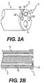
- An exterior face 12 of distal tip 4 can define openings in communication with one or more channels 15, 16 in elongate member 3. These openings may fluidly connect channels 15, 16 in elongate member 3 to face 12 of medical device 1 and to regions exterior of medical device 1, as shown in FIGS. 2A-2B .
- an instrument passed through a working channel may exit a working opening 19 in distal tip 4 so that the instrument can protrude from medical device 1 to a work site.
- the instrument may be configured as an end-effector attached at a distal region of medical device 1 and configured to pass through working opening 19.
- the openings on face 12 of distal tip 4 may have any size, cross-sectional area, shape, and/or configuration. Further, while FIGS. 2A-3B depict two channels 15, 16 exiting or terminating in distal tip 4, distal tip 4 may include an exit or termination point for only one channel, or for more than two channels.
- the number, arrangement, or type of channels included in elongate member 3 and the number, arrangement, or type of openings in distal tip 4 depicted in the embodiments are exemplary. Medical device 1 may include any suitable number, type, or arrangement of channels or openings. Further, the ratio of channels in elongate member 3 to openings in distal tip 4 need not be one-to-one.
- face 12 of distal tip 4 includes opening 19 for a working channel, two openings 20, 20' for irrigation, suction, and/or insufflation channels, an opening 18 for an illumination unit 28, and an imaging opening 17 for an imaging unit 27.
- illumination opening 18 and imaging opening 17 may include windows or lenses to cover and protect illumination unit 28 and imaging unit 27, respectively.
- Face 12 of distal tip 4 can include any type, number, and/or configuration of openings or units.
- Units positioned in the openings of distal tip 4 may be adjacent to, flush with, or protruding from distal tip 4 and/or the channels in which they are oriented. Further, units may be moveable in any direction relative to distal tip 4. For instance, illumination unit 28 or imaging unit 27 may be moveable within openings 18 or 17, respectively, in order to aid with visualization and imaging. In other embodiments, the units in distal tip 4 may be stationary.
- Distal tip 4 may encase various optical components.
- optical components can include image detectors, light sources, fiberoptics, light shields, filters, lenses, etc.
- medical device 1 may include illumination unit 28 to illuminate a field of view at the work site and imaging unit 27 to allow a surgeon to see the work site from outside the body and to remotely operate medical device 1 or instruments passed through working opening 19 to perform a desired diagnostic/therapeutic procedure at the work site.
- Imaging unit 27 may be configured to capture images and/or full-motion video images.
- Illumination unit 28 may be configured to illuminate internal body lumens and/or cavities of a patient.
- Illumination unit 28 may be configured to provide both far-field and near-field illumination.
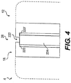
- FIG. 4 depicts a cross-section of an exemplary illumination unit 28 in illumination opening 18 located on distal tip 4.
- Illumination unit 28 may include one or more near-field diffusers 223, 223' and one or more far-field apertures 222.
- Far-field aperture 222 can be located adjacent to, on, or be formed as a part of face 12 of distal tip 4.
- Far-field aperture 222 may be circular, oval, rectangular, or any other suitable shape.
- Far-field aperture 222 may vary in cross-sectional shape or size from a distal end to a proximal end. For instance, far-field aperture 222 may be conical or bowl-shaped.
- near-field diffuser 223 may extend longitudinally away from far-field aperture 222 in a proximal direction. In one embodiment, a single near-field diffuser 223 may substantially surround the periphery of far-field aperture 222. In some embodiments, a plurality of near-field diffusers 223, 223' may be located around the periphery of far-field aperture 222.
- Distal tip 4 and near-field diffusers 223, 223' can be monolithically formed (e.g., formed in one piece), or distal tip 4 and near-field diffusers 223, 223' may be separate components.
- distal tip 4 may itself be formed of a near-field diffuser 223 and may surround the periphery of far-field aperture 222, or may form the opening that forms far-field aperture 222.
- illumination opening 18 on face 12 of distal tip 4 may define far-field aperture 222.
- distal tip 4 acts as near-field diffuser 223, it can be formed, for example, with a plastic or glass material.
- distal tip 4 may be formed with a transparent material and can be configured, for example, to filter or enhance certain wavelengths of light.
- the material used to form distal tip 4 can be selected based on the material's optical properties, such as its ability to transmit light of a particular wavelength(s).
- Distal tip 4 can be, for example, molded or post-processed to form optically transmissive regions.
- Distal tip 4 may be made of a translucent plastic or material by any suitable method, including, for example, injection molding, machining, or lithography.
- distal tip 4 may be formed of an acrylic polymer filled with a diffuser, such as titanium dioxide. The acrylic material may create a scatter effect to light that enters distal tip 4.
- Scattering may be facilitated by any number of ways known in the art, including fillers, opaque materials, bubbles, diffusing or opaque coatings, surface treatments, or patterns.
- one or more portions of distal tip 4 may include holes, pores, particulates, bubbles, or may be partially or substantially hollowed out, or may include any suitable configuration for affecting light transmission.
- a light source 224 may be configured to direct light through near-field diffuser 223 and far-field aperture 222.
- Light source 224 can include, for instance, one or more optical fibers, one or more LEDs, or any other suitable light source or combination thereof.
- Light source 224 can be formed of quartz, glass, plastic, or any other suitable material.
- a single light source e.g., a single optical fiber or a single LED, can be configured to direct light through both near-field diffuser 223 and far-field aperture 222.
- Light source 224 may be positioned in line with far-field aperture 222, and one or more portions of light source 224 may be substantially surrounded by near-field diffuser 223. Light source 224 may be adjacent to or placed in contact with near-field diffuser 223. In one embodiment, light source 224 may extend longitudinally away from far-field aperture 222 in a proximal direction. For example, light source 224 may extend from a proximal region through an illumination channel in elongate member 3 to illumination unit 28 in illumination opening 18 of distal tip 4. Light source 224 may be configured to direct light through both near-field diffuser 223 and far-field aperture 222, and me located distal to one or both of near-field diffuser 223 and far-field aperture 222.
- Light source 224 may be recessed within distal tip 4 proximal to face 12. In other embodiments, light source 224 may be flush with face 12, or may protrude distally from face 12 of distal tip 4. Light source 224 may be moveable relative to distal tip 4, for example, axially or rotationally.
- near-field diffuser 2223 may be configured to spread the light from light source 224 that is discharged from illumination unit 28 to produce a softer light that reduces harsh glare, saturation and/or hard shadows.
- near-field images captured by imaging unit 27 may be softer and clearer. This can result in a uniform near-field illumination pattern.
- the size of the aperture can determine the down-lumen spot size and the down-lumen visualization distance.
- the size of far-field aperture 222 can be smaller or larger than the tip of light source 224.
- the aperture size can be variable.
- far-field aperture 222 may be operably coupled to proximal handle assembly 2 and configured so that a user may adjust the size of far-field aperture 222.
- one or more illumination units 28 may be operably connected to one or more imaging units 27.
- the size of aperture 222 may be automatically adjusted based on signals received and/or processed from imaging unit 27.
- the size of far-field aperture 222 may be fixed.
- Far-field aperture 222 may also include a cover, filter, diffuser, or any other suitable structure to control far-field illumination.
- distal tip 4 may include multiple light sources 224 - either a bundle of optical fibers or an array of LEDs in a single illumination unit 28, or multiple illumination units 28 using single or multiple optical fibers or LEDs - to increase light intensity and/or to alter the illumination pattern.
- Imaging unit 27 may include a camera, lens, digital-imaging chip, or other image-receiving device, which may transmit signals using wire or cable within a channel of elongate member 3.
- illumination unit 28 may be operably connected to handle assembly 2 and may provide a communication pathway between a control module and both imaging unit 27 and illumination unit 28.
- a connector may provide electronic signaling pathways for imaging unit 27 to transmit image data to a control module, for a control module to transmit image control signals to imaging unit 27, and for a control module to control light delivered from light source 224 to illumination unit 28.
- light source 224 may be housed in handle assembly 2, and illumination unit 28 may be operably connected to light source 224 within handle assembly 2. Light source 224 may then be operably coupled to a control module via a connector.
- a connector may include any appropriate linkage configured to provide signaling capabilities and communication between a control module and both imaging unit 27 and illumination unit 28, such as, for example, one or more electrical wires, an electrical conduit, or other suitable connectors.
- a connector may also include a suitable structure configured to readily attach and detach from a control module, such as, for example, a detachable point-to-point adapter, a detachable splice, and a detachable multi-port adapter.
- the one or more electrical wires may extend from handle assembly 2, through a channel in elongate member 3, and connect to imaging unit 27 in imaging opening 17 at distal tip 4.
- Illumination unit 28 may also extend from handle assembly 2, through a channel in elongate member 3, and terminate in illumination opening 18 at distal tip 4.
- light delivered from light source 224 and/or illumination unit 28 may be colored or white, filtered or unfiltered, pulsing or steady, intense or dull, e.g., and these characteristics may be constant or may change, for instance, automatically, in response to user control, or according to preset conditions.
Landscapes
- Health & Medical Sciences (AREA)
- Life Sciences & Earth Sciences (AREA)
- Surgery (AREA)
- Optics & Photonics (AREA)
- Physics & Mathematics (AREA)
- Engineering & Computer Science (AREA)
- Biomedical Technology (AREA)
- Molecular Biology (AREA)
- Pathology (AREA)
- Nuclear Medicine, Radiotherapy & Molecular Imaging (AREA)
- Biophysics (AREA)
- Heart & Thoracic Surgery (AREA)
- Medical Informatics (AREA)
- Radiology & Medical Imaging (AREA)
- Animal Behavior & Ethology (AREA)
- General Health & Medical Sciences (AREA)
- Public Health (AREA)
- Veterinary Medicine (AREA)
- Microelectronics & Electronic Packaging (AREA)
- Endoscopes (AREA)
Abstract
an elongate member, including:
a distal end, and
a channel extending through the elongate member to the distal end; and
a cap at the distal end of the elongate member; and
an illumination unit extending through the channel to the cap, wherein the illumination unit is configured to illuminate an area distal to the cap, and wherein the illumination unit includes:
a light source configured to emit light,
a near-field diffuser configured to diffuse a first portion of light emitted by the light source, and emit the diffused first portion of light into the area distal to the cap,
a far-field aperture wherein a second portion of light emitted by the light source is unobstructed as the second portion of light leaves the light source, enters the aperture, and exits the aperture into the area distal to the cap
Description
- This application claims the benefit of priority from
U.S. Provisional Application No. 61/659,258, filed on June 13, 2012 - Embodiments of the present disclosure include medical devices, and more particularly, medical devices including enhanced visualization and methods of use.
- Adequate visualization has posed a challenge in the exploration and treatment of internal areas of the human body. Visualization may be especially troublesome in minimally invasive procedures in which small diameter, elongate instruments, such as catheters or endoscopes, may be navigated through natural passageways and cavities of a patient to a region of interest (work site).
- In conventional minimally invasive procedures, an endoscope or catheter may be inserted into the body for diagnostic or therapeutic purposes. A distal end of an endoscope may be inserted into the body through an opening in the body. This opening may be a natural anatomic opening, such as, for example, the mouth, rectum, vagina, etc., or an incision made on the body. The endoscope may be pushed into the body such that the distal end of the endoscope proceeds from the point of insertion to a work site within the body by traversing a body lumen, for example, the gastric, pulmonary, esophageal, or urological tracts.
- Once inside the body, performing diagnostic and treatment procedures requires sufficiently clear visualization. Navigating and identifying regions of interest may require down-lumen visualization. For down-lumen visualization, high-intensity light with a small spot size may be directed towards the center of a body lumen. When directed towards near-field objects, however, this light may become saturating and image details may be lost. By contrast, visualizing the near-field lumen periphery may require wide-angle, low-intensity light. While such low-intensity light avoids saturation of near-field objects, it may not provide enough illumination to visualize down lumen. These variations in illumination requirements may make navigation and visualization of the work site difficult, potentially increasing procedure time and decreasing accuracy, and thus increasing the possibility of complications for the patient.
- Conventional endoscopes may utilize complex and/or expensive systems, such as arrays of optical fibers or light-emitting diodes ("LEDs") at a distal region of an endoscope in order to provide uniform illumination in both the near and far fields. But such devices may increase the size of endoscopes, making them cumbersome to maneuver and restricting the cavities through which they may pass. Additionally, they may increase the cost of manufacturing and maintaining these instruments.
- Accordingly, a need exists for a compact, cost-effective visualization unit capable of achieving adequate uniform far-field and near-field illumination. The medical devices and related methods of the present disclosure are directed to improvements in the existing technology and overcome at least some of the deficiencies in the prior art.
- Various embodiments of the disclosure may include one or more of the following aspects.
- In accordance with one embodiment, a medical device may comprise an elongate member including a proximal region and a distal region. The elongate member can further include a handle at the proximal region and a tip at the distal region. The tip can include one or more openings, wherein one of the one or more openings at least partially houses an illumination unit. The illumination unit may further comprise a light source, a near-field diffuser proximate to the light source, and a far-field aperture proximate to the light source.
- In accordance with another embodiment, a medical device may comprise an elongate member including a proximal region and a distal region and one or more channels extending from the proximal region to the distal region. A channel of the one or more channels may be configured to carry light or a light signal to a distal region of the elongate member. The light or light signal may be from only one optical fiber or only one light emitting diode. Additionally, the medical device can include a near-field diffuser at the distal region of the elongate member configured to provide near-field illumination. The medical device can also include a far-field aperture at the distal region of the elongate member configured to provide far-field illumination. The medical device may also include an imaging unit.
- In this respect, before explaining multiple embodiments of the present disclosure in detail, it is to be understood that the present disclosure is not limited in its application to the details of construction and to the arrangements of the components set forth in the following description or illustrated in the drawings. The present disclosure is capable of embodiments in addition to those described and of being practiced and carried out in various ways. Also, it is to be understood that the phraseology and terminology employed herein, as well as in the abstract, are for the purpose of description and should not be regarded as limiting.
- The accompanying drawings illustrate certain exemplary embodiments of the present disclosure and, together with the description, serve to explain the principles of the present disclosure. As such, those skilled in the art will appreciate that the conception upon which this disclosure is based may readily be used as a basis for designing other structures, methods, and systems for carrying out the several purposes of the present disclosure. It is important, therefore, to recognize that the claims should be regarded as including such equivalent constructions insofar as they do not depart from the spirit and scope of the present disclosure.
-
-
FIG. 1 illustrates a medical device, according to an exemplary disclosed embodiment; -
FIG. 2A illustrates a perspective view of a distal region of a medical device, according to an exemplary disclosed embodiment; -
FIG. 2B illustrates a cross-sectional view of a distal region of a medical device, according to an exemplary disclosed embodiment; -
FIGS. 3A-3B illustrate end views of exemplary distal ends of a medical device, according to exemplary disclosed embodiments; and -
FIG. 4 illustrates a cross-sectional view of a distal region of a medical device, according to an exemplary disclosed embodiment. - Reference will now be made in detail to exemplary embodiments of the invention, examples of which are illustrated in the accompanying drawings. Wherever possible, the same reference numbers will be used throughout the drawings to refer to the same or like parts. Also, any aspect set forth in any embodiment may be used with any other embodiment set forth herein.
- The terms "proximal" and "distal" are used herein to refer to the relative positions of the components of an exemplary medical device. When used herein, "proximal" refers to a position relatively closer to the exterior of the body or closer to the physician, or other user, using the medical device. In contrast, "distal" refers to a position relatively further away from the user using the medical device or closer to the interior of the body.
- While the described systems and methods may generally refer to medical devices and procedures, the described systems and their methods of use are not limited to any particular medical diagnostic or treatment procedure. Moreover, the systems and devices described herein can perform nonmedical applications, such as the inspection or repair of machinery.
-
FIG. 1 illustrates amedical device 1 according to an exemplary embodiment.Medical device 1 may include any device configured to allow an operator to access and view internal body anatomies of a patient. Such devices include, for instance, an endoscope, a catheter, a guide tube, or the like.Medical device 1 may be configured for insertion into a variety of body lumens and/or cavities, such as, for example, any portion of a urinary tract including a ureter, a gastrointestinal lumen including an esophagus, a biliary duct, pancreatic duct, a vascular lumen, an airway, and the like.Medical device 1 also may be used, for example, in natural orifice transluminal endoscopic surgery (NOTES) procedures or single incision laparoscopic surgical (SILS) procedures. Accordingly,medical device 1 can be shaped and sized for placement into a patient via a body cavity or an incision. For purposes of the present disclosure,medical device 1 may include a single-use, disposable endoscope, ormedical device 1 may include a reusable endoscope. -
Medical device 1 may include anelongate member 3 having a proximal end and a distal end. Ahandle assembly 2 may be operably connected to a proximal region ofelongate member 3 and configured for steering and/or controlling a distal region ofmedical device 1.Medical device 1 may be used alone or as part of a larger surgical system (not shown). Examples of such surgical systems are described inU.S. Patent No. 6,736,773 , andU.S. Patent Publication Nos. 2011/0213206 and2008/0188868 , all of which are incorporated herein in their entirety by reference. Adistal tip 4 may be operably connected to a distal region ofelongate member 3 and configured for positioning at a work site in a body cavity.Elongate member 3 may be flexible, or may include one or more portions that are flexible, to allowelongate member 3 to be maneuvered within the body and to traverse tortuous anatomical lumens. For instance,elongate member 3 may be uniformly flexible or may include a plurality of portions having varying degrees of flexibility or rigidity. In some embodiments,elongate member 3 may be rigid, or may include one or more portions that are rigid. -
Elongate member 3 may be formed of any suitable material, for instance, rubber, silicon, plastic, stainless steel, metal-polymer composites, and metal alloys. In some embodiments,elongate member 3 may include layers of different materials and reinforcements.Elongate member 3 may have any cross-sectional shape and/or configuration and may be any desired dimension that can be received in a body cavity. In some embodiments,elongate member 3 may be made of, or coated with, a polymeric or lubricious material to enablemedical device 1 to more easily pass through a body cavity. -
Elongate member 3 can further include one ormore channels 15, 16 (shown inFIG. 2B ) extending throughelongate member 3 and/or handleassembly 2 and/ordistal tip 4.Channels Medical device 1 andchannels channels channels -
Distal tip 4 may be located at a distal region ofelongate member 3. Anexterior face 12 ofdistal tip 4 can define openings in communication with one ormore channels elongate member 3. These openings may fluidly connectchannels elongate member 3 to face 12 ofmedical device 1 and to regions exterior ofmedical device 1, as shown inFIGS. 2A-2B . For instance, an instrument passed through a working channel may exit a workingopening 19 indistal tip 4 so that the instrument can protrude frommedical device 1 to a work site. In another embodiment, the instrument may be configured as an end-effector attached at a distal region ofmedical device 1 and configured to pass through workingopening 19. - The openings on
face 12 ofdistal tip 4 may have any size, cross-sectional area, shape, and/or configuration. Further, whileFIGS. 2A-3B depict twochannels distal tip 4,distal tip 4 may include an exit or termination point for only one channel, or for more than two channels. The number, arrangement, or type of channels included inelongate member 3 and the number, arrangement, or type of openings indistal tip 4 depicted in the embodiments are exemplary.Medical device 1 may include any suitable number, type, or arrangement of channels or openings. Further, the ratio of channels inelongate member 3 to openings indistal tip 4 need not be one-to-one. - In some embodiments,
distal tip 4 may be integral with a distal region ofelongate member 3, while in other embodiments,distal tip 4 may be one or more parts separate from a distal region ofelongate member 3. In such embodiments,distal tip 4 may be secured to a distal region ofelongate member 3 by, for example, an interference fit, a snap fit, threads, adhesive bonding, lock and key fit, or any other suitable securing mechanism.Distal tip 4 may be a removable or replaceable distal tip and may be reusable or disposable. Multiple types and/or configurations ofdistal tip 4 may be available for interchangeable use with a distal region ofelongate member 3. - Further,
distal tip 4 may have any useful shape to aid with procedures, deliver light, and/or diffuse light. For example,distal tip 4 may be cylindrical, bulbous, hemispherical, concave, or may have angled surfaces. In some embodiments,distal tip 4 may have rounded or beveled edges to provide increased patient comfort and to reduce the risk of injury to the patient. - In the embodiments in
FIGS. 2A-2B and3A-3B , face 12 ofdistal tip 4 includesopening 19 for a working channel, twoopenings opening 18 for anillumination unit 28, and animaging opening 17 for animaging unit 27. In addition,illumination opening 18 andimaging opening 17 may include windows or lenses to cover and protectillumination unit 28 andimaging unit 27, respectively.Face 12 ofdistal tip 4 can include any type, number, and/or configuration of openings or units. - Units positioned in the openings of
distal tip 4 may be adjacent to, flush with, or protruding fromdistal tip 4 and/or the channels in which they are oriented. Further, units may be moveable in any direction relative todistal tip 4. For instance,illumination unit 28 orimaging unit 27 may be moveable withinopenings distal tip 4 may be stationary. -
Distal tip 4 may encase various optical components. For example, such optical components can include image detectors, light sources, fiberoptics, light shields, filters, lenses, etc. In the embodiment shown inFIGS. 2A-2B and3A-3B ,medical device 1 may includeillumination unit 28 to illuminate a field of view at the work site andimaging unit 27 to allow a surgeon to see the work site from outside the body and to remotely operatemedical device 1 or instruments passed through workingopening 19 to perform a desired diagnostic/therapeutic procedure at the work site.Imaging unit 27 may be configured to capture images and/or full-motion video images.Illumination unit 28 may be configured to illuminate internal body lumens and/or cavities of a patient. -
Illumination unit 28 may be configured to provide both far-field and near-field illumination.FIG. 4 depicts a cross-section of anexemplary illumination unit 28 inillumination opening 18 located ondistal tip 4.Illumination unit 28 may include one or more near-field diffusers 223, 223' and one or more far-field apertures 222. Far-field aperture 222 can be located adjacent to, on, or be formed as a part offace 12 ofdistal tip 4. Far-field aperture 222 may be circular, oval, rectangular, or any other suitable shape. Far-field aperture 222 may vary in cross-sectional shape or size from a distal end to a proximal end. For instance, far-field aperture 222 may be conical or bowl-shaped. In one embodiment, near-field diffuser 223 may extend longitudinally away from far-field aperture 222 in a proximal direction. In one embodiment, a single near-field diffuser 223 may substantially surround the periphery of far-field aperture 222. In some embodiments, a plurality of near-field diffusers 223, 223' may be located around the periphery of far-field aperture 222. -
Distal tip 4 and near-field diffusers 223, 223' can be monolithically formed (e.g., formed in one piece), ordistal tip 4 and near-field diffusers 223, 223' may be separate components. For instance, in some embodiments,distal tip 4 may itself be formed of a near-field diffuser 223 and may surround the periphery of far-field aperture 222, or may form the opening that forms far-field aperture 222. In one embodiment,illumination opening 18 onface 12 ofdistal tip 4 may define far-field aperture 222. Whendistal tip 4 acts as near-field diffuser 223, it can be formed, for example, with a plastic or glass material. In some embodiments,distal tip 4 may be formed with a transparent material and can be configured, for example, to filter or enhance certain wavelengths of light. The material used to formdistal tip 4 can be selected based on the material's optical properties, such as its ability to transmit light of a particular wavelength(s).Distal tip 4 can be, for example, molded or post-processed to form optically transmissive regions.Distal tip 4 may be made of a translucent plastic or material by any suitable method, including, for example, injection molding, machining, or lithography. In one embodiment,distal tip 4 may be formed of an acrylic polymer filled with a diffuser, such as titanium dioxide. The acrylic material may create a scatter effect to light that entersdistal tip 4. Scattering may be facilitated by any number of ways known in the art, including fillers, opaque materials, bubbles, diffusing or opaque coatings, surface treatments, or patterns. For example, one or more portions ofdistal tip 4 may include holes, pores, particulates, bubbles, or may be partially or substantially hollowed out, or may include any suitable configuration for affecting light transmission. - A
light source 224 may be configured to direct light through near-field diffuser 223 and far-field aperture 222.Light source 224 can include, for instance, one or more optical fibers, one or more LEDs, or any other suitable light source or combination thereof.Light source 224 can be formed of quartz, glass, plastic, or any other suitable material. In one embodiment, a single light source, e.g., a single optical fiber or a single LED, can be configured to direct light through both near-field diffuser 223 and far-field aperture 222. -
Light source 224 may be positioned in line with far-field aperture 222, and one or more portions oflight source 224 may be substantially surrounded by near-field diffuser 223.Light source 224 may be adjacent to or placed in contact with near-field diffuser 223. In one embodiment,light source 224 may extend longitudinally away from far-field aperture 222 in a proximal direction. For example,light source 224 may extend from a proximal region through an illumination channel inelongate member 3 toillumination unit 28 inillumination opening 18 ofdistal tip 4.Light source 224 may be configured to direct light through both near-field diffuser 223 and far-field aperture 222, and me located distal to one or both of near-field diffuser 223 and far-field aperture 222. -
Light source 224 may be recessed withindistal tip 4 proximal to face 12. In other embodiments,light source 224 may be flush withface 12, or may protrude distally fromface 12 ofdistal tip 4.Light source 224 may be moveable relative todistal tip 4, for example, axially or rotationally. - As light from
light source 224 passes through near-field diffuser 223, light rays may be spread out at a large angle such that light is directed towards the periphery of the body lumen into whichdistal tip 4 may be inserted. Near-field diffuser 223 may be configured to spread the light fromlight source 224 that is discharged fromillumination unit 28 to produce a softer light that reduces harsh glare, saturation and/or hard shadows. Thus, near-field images captured by imagingunit 27 may be softer and clearer. This can result in a uniform near-field illumination pattern. - The material and thickness of near-
field diffuser 223 may affect the diffusing angle and uniformity of the illumination pattern produced byillumination unit 28. Near-field diffuser 223 can be formed of any suitable structure, material, or combination of materials for spreading light fromlight source 224, for example, ground glass, opal glass, grayed glass, and various white opaque plastics, such as titanium-filled acrylic and glass-filled polycarbonate. In some embodiments,distal tip 4 may be injection molded from any suitable, optically clear material that may be loaded with 1 to 15% titanium dioxide, and thus, the material ofdistal tip 4 may function as a diffuser. - Light from
light source 224 entering far-field aperture 222 may not be diffused and may therefore be directed out ofillumination unit 28 collinear withdistal tip 4. Far-field aperture 222 may be configured to direct higher-intensity, concentrated light fromillumination unit 28. Accordingly, light passing through far-field aperture 222 can form a centralized, compact illumination profile, allowing for a uniform far-field illumination pattern and improved down-lumen visualization. - The size of the aperture can determine the down-lumen spot size and the down-lumen visualization distance. The size of far-
field aperture 222 can be smaller or larger than the tip oflight source 224. In some embodiments, the aperture size can be variable. For instance, far-field aperture 222 may be operably coupled toproximal handle assembly 2 and configured so that a user may adjust the size of far-field aperture 222. In one embodiment, one ormore illumination units 28 may be operably connected to one ormore imaging units 27. In this embodiment, for instance, the size ofaperture 222 may be automatically adjusted based on signals received and/or processed fromimaging unit 27. In other embodiments, the size of far-field aperture 222 may be fixed. Far-field aperture 222 may also include a cover, filter, diffuser, or any other suitable structure to control far-field illumination. - The properties of far-
field aperture 222 and near-field diffuser 223 can be tailored depending on the requirements of the type ofmedical device 1 used or the therapeutic or diagnostic procedure performed. Furthermore,distal tip 4 may include multiple light sources 224 - either a bundle of optical fibers or an array of LEDs in asingle illumination unit 28, ormultiple illumination units 28 using single or multiple optical fibers or LEDs - to increase light intensity and/or to alter the illumination pattern. - In some embodiments,
distal tip 4 may house components that are unique todistal tip 4 and do not extend through channels inelongate member 3, or that only partially extend through channels. For instance,illumination opening 18 indistal tip 4 may or may not fluidly connect with one or more corresponding channels extending throughelongate member 3 and instead may terminate within a recess indistal tip 4. For example, while workingopening 19 indistal tip 4 may fluidly connect with a working channel inelongate member 3, optical components may or may not extend through corresponding channels inelongate member 3, or may only partially extend through a channel.Imaging unit 27 and/orillumination unit 28 may or may not be entirely contained inopenings distal tip 4. - In one embodiment, an optical component can extend within an opening of
distal tip 4 such that a distal end portion of the optical component is encased withindistal tip 4 and a proximal end portion of the component can extend out a proximal end ofdistal tip 4 and through a channel ofelongate member 3. For example, optical components having a power line or signal line, such as light source 224 (FIG. 4 ) inillumination unit 28 or a component inimaging unit 27, can have a power line or signal line extending out of a proximal end ofdistal tip 4.Imaging unit 27 can be coupled to a proximal imaging controller (not shown) via conductors, such as electrical wires, passing through a channel ofmedical device 1, as described above. Thus, images of a body lumen can be captured by imagingunit 27 and processed by the imaging controller. The images can also be communicated to an eyepiece or display device (not shown).Imaging unit 27 may include a camera, lens, digital-imaging chip, or other image-receiving device, which may transmit signals using wire or cable within a channel ofelongate member 3. - As alluded to above,
medical device 1 may be coupled to a control module and may include imaging electronics configured to process and/or transfer signals received fromimaging unit 27 to a display (not shown) for viewing by a user. The control module may also be operably connected tolight source 224, such as a fiber optic source, halogen source, or LED source, configured to deliver light toillumination unit 28, and/or illumination electronics configured to process and/or transfer signals controllingillumination unit 28. One or more actuators or buttons may be disposed on the control module to controlillumination unit 28 and/orimaging unit 27. Alternatively, the one or more actuators or buttons may be disposed onhandle assembly 2 ofmedical device 1 for controllingillumination unit 28 orimaging unit 27. - In one embodiment,
illumination unit 28 may be operably connected to handleassembly 2 and may provide a communication pathway between a control module and bothimaging unit 27 andillumination unit 28. For example, a connector may provide electronic signaling pathways forimaging unit 27 to transmit image data to a control module, for a control module to transmit image control signals toimaging unit 27, and for a control module to control light delivered fromlight source 224 toillumination unit 28. It should be appreciated that in other embodiments, however,light source 224 may be housed inhandle assembly 2, andillumination unit 28 may be operably connected tolight source 224 withinhandle assembly 2.Light source 224 may then be operably coupled to a control module via a connector. - A connector may include any appropriate linkage configured to provide signaling capabilities and communication between a control module and both
imaging unit 27 andillumination unit 28, such as, for example, one or more electrical wires, an electrical conduit, or other suitable connectors. A connector may also include a suitable structure configured to readily attach and detach from a control module, such as, for example, a detachable point-to-point adapter, a detachable splice, and a detachable multi-port adapter. The one or more electrical wires may extend fromhandle assembly 2, through a channel inelongate member 3, and connect toimaging unit 27 inimaging opening 17 atdistal tip 4.Illumination unit 28 may also extend fromhandle assembly 2, through a channel inelongate member 3, and terminate inillumination opening 18 atdistal tip 4. - A user may control light directed through
light source 224 andillumination unit 28 jointly or independently of a control system to optimize visualization. One or more than onelight source 224 and one or more than oneimaging unit 28 may be centerplated ondistal tip 4 and controlled by a user. Further, a user may independently control the characteristics of light using, for instance, controls located onhandle assembly 2, or a control system (not shown) may control the characteristics of light. The characteristics may include intensity, wavelength, polarization, color, frequency, phase, or any other characteristic that can vary the level of illumination directed throughlight source 224 and/orillumination unit 28. For instance, light delivered fromlight source 224 and/orillumination unit 28 may be colored or white, filtered or unfiltered, pulsing or steady, intense or dull, e.g., and these characteristics may be constant or may change, for instance, automatically, in response to user control, or according to preset conditions. - Any aspect set forth in any embodiment may be used with any other embodiment set forth herein. Every device and apparatus set forth herein may be used in any suitable medical procedure, may be advanced through any suitable body lumen and body cavity, and may be used for treatment or observation of any suitable body portion. For example, the apparatuses and methods described herein may be used in any natural body lumen or tract, including those accessed orally, vaginally, or rectally.
- The many features and advantages of the present disclosure are apparent from the detailed specification, and thus, it is intended by the appended claims to cover all such features and advantages of the present disclosure that fall within the true spirit and scope of the present disclosure. Further, since numerous modifications and variations will readily occur to those skilled in the art, it is not desired to limit the present disclosure to the exact construction and operation illustrated and described, and accordingly, all suitable modifications and equivalents may be resorted to, falling within the scope of the present disclosure.
- Further preferred and/or additional embodiments of the invention relate to the following aspects:
- 1. A medical device, comprising:
- an elongate member including a proximal region and a distal region;
- a handle at the proximal region of the elongate member, and
- a tip at the distal region of the elongate member, wherein the tip includes one or more openings, wherein one of the one or more openings at least partially houses an illumination unit, comprising:
- a light source;
- a near-field diffuser proximate to the light source; and
- a far-field aperture proximate to the light source.
- 2. The medical device of
aspect 1, wherein the illumination unit is configured to provide near-field illumination and far-field illumination. - 3. The medical device of
aspect 1, wherein the near-field diffuser is adjacent to the light source and substantially surrounds a portion of the light source, and the far-field aperture is distal to the light source. - 4. The medical device of
aspect 1, wherein the tip is monolithic with the near-field diffuser. - 5. The medical device of
aspect 4, wherein the tip or the near-field diffuser defines the far-field aperture. - 6. The medical device of
aspect 1, wherein the elongate member includes one or more channels extending from the proximal region to the distal region. - 7. The medical device of aspect 6, wherein the light source is operably connected to the handle by a connector extending through one of the one or more channels in the elongate member.
- 8. The medical device of
aspect 1, wherein the distal face of the light source is recessed within the tip proximal to a distal face of the tip. - 9. The medical device of
aspect 1, wherein the tip further comprises at least one opening containing an imaging unit. - 10. The medical device of aspect 9, wherein the imaging unit is operably connected to the illumination unit.
- 11. The medical device of aspect 9, wherein the imaging unit and the illumination unit are operably connected to a controller external to the medical device.
- 12. The medical device of
aspect 1, wherein the near-field diffuser is glass or plastic. - 13. The medical device of
aspect 1, wherein the light source includes only one optical fiber. - 14. The medical device of
aspect 1, wherein the light source includes only one light emitting diode. - 15. A medical device, comprising:
- an elongate member including a proximal region and a distal region, and including one or more channels extending from the proximal region to the distal region, wherein a channel of the one or more channels is configured to carry light or a light signal to a distal region of the elongate member; and wherein the light or light signal is from only one optical fiber or only one light emitting diode;
- a near-field diffuser at the distal region of the elongate member and configured to provide near-field illumination;
- a far-field aperture at the distal region of the elongate member, wherein the far-field aperture is configured to provide far-field illumination; and
- an imaging unit.
- 16. The medical device of
aspect 15, wherein the near-field diffuser is monolithic with the distal region and the far-field aperture is defined by the distal region. - 17. The medical device of
aspect 15, wherein the channel includes the only one optical fiber, the near-field diffuser surrounds at least a portion of the optical fiber and the far-field aperture is narrower than a width of the optical fiber. - 18. The medical device of
aspect 15, wherein the far-field aperture is located distal to the optical fiber or the light emitting diode. - 19. The medical device of
aspect 15, wherein the far-field aperture is located distal to a distal face of the near-field diffuser. - 20. The medical device of
aspect 15, further comprising a handle assembly at the proximal region of the elongate member, wherein the handle assembly houses at least part of the optical fiber or at least part of the light emitting diode.
Claims (15)
- A medical device (1), comprising:
an elongate member (3), including:a distal end, anda channel extending through the elongate member (3) to the distal end; anda cap (4) at the distal end of the elongate member (3); andan illumination unit (28) extending through the channel to the cap (4), wherein the illumination unit (28) is configured to illuminate an area distal to the cap (4), and wherein the illumination unit (28) includes:a light source (224) configured to emit light,a near-field diffuser (223, 223') configured to diffuse a first portion of light emitted by the light source (224), and emit the diffused first portion of light into the area distal to the cap (4),a far-field aperture (222), wherein a second portion of light emitted by the light source (224) is unobstructed as the second portion of light leaves the light source (224), enters the aperture (222), and exits the aperture (222) into the area distal to the cap (4). - The device of claim 1, wherein a layer of material forming the far-field aperture (222) is light-transmissive.
- The device of claim 2, wherein:the layer of material forming the far-field aperture (222) is on an outer surface of the near-field diffuser (223, 223'); orthe layer of material forming the far-field aperture (222) includes a flange portion distal to a distal end of the light source (224).
- The device of any one of claims 1-3, wherein the near-field diffuser (223, 223') includes one or more layers of material enveloping the light source (224).
- The device of any one of claims 1-4, wherein a width of the far-filed aperture (222) is less than a width of a distal portion of the light source (224).
- The device of any one of claims 1-5, wherein the second portion of light emitted from the far-field aperture (222) is at least one of more centralized, more concentrated, and higher-intensity than the first portion of light emitted from the near-field diffuser (223, 223').
- The device of any one of claim 1-6, wherein the near-field diffuser (223, 223') is within the cap (4).
- The device of any one of claim 1-7, wherein the aperture (222) is located at a distal most face (12) of the cap (4).
- The device of any one of claim 1-8, wherein the illumination unit (28) is operably connected to one or more imaging units (27).
- The device of claim 9, wherein a size of the far-field aperture (222) is automatically adjusted based on signals received and/or processed from the imaging unit (27).
- The device of any one of claims 1-10, wherein the far-field aperture (222) includes a cover, filter, or diffuser to control far-field illumination.
- The device of any one of claims 1-11, wherein the illumination unit (28) is entirely contained in an opening (18) in the cap (4).
- The device of any one of claims 9-12, wherein the imaging unit (27) is entirely contained in an opening (17) in the cap (4).
- The device of any one of claims 1-13, wherein the light source (224) includes one or more optical fibers, one or more LEDs, or a combination thereof.
- The device of any one of claims 1-14, wherein a single light source (224) is configured to driect light through both the near-field diffuser (223, 223') and far-field aperture (222).
Applications Claiming Priority (3)
| Application Number | Priority Date | Filing Date | Title |
|---|---|---|---|
| US201261659258P | 2012-06-13 | 2012-06-13 | |
| EP13724070.1A EP2861124B1 (en) | 2012-06-13 | 2013-05-02 | Medical device visualization system |
| PCT/US2013/039310 WO2013188014A1 (en) | 2012-06-13 | 2013-05-02 | Medical device visualization system |
Related Parent Applications (2)
| Application Number | Title | Priority Date | Filing Date |
|---|---|---|---|
| EP13724070.1A Division-Into EP2861124B1 (en) | 2012-06-13 | 2013-05-02 | Medical device visualization system |
| EP13724070.1A Division EP2861124B1 (en) | 2012-06-13 | 2013-05-02 | Medical device visualization system |
Publications (2)
| Publication Number | Publication Date |
|---|---|
| EP3566636A1 true EP3566636A1 (en) | 2019-11-13 |
| EP3566636B1 EP3566636B1 (en) | 2024-02-21 |
Family
ID=48468787
Family Applications (2)
| Application Number | Title | Priority Date | Filing Date |
|---|---|---|---|
| EP19176063.6A Active EP3566636B1 (en) | 2012-06-13 | 2013-05-02 | Medical device visualization system |
| EP13724070.1A Active EP2861124B1 (en) | 2012-06-13 | 2013-05-02 | Medical device visualization system |
Family Applications After (1)
| Application Number | Title | Priority Date | Filing Date |
|---|---|---|---|
| EP13724070.1A Active EP2861124B1 (en) | 2012-06-13 | 2013-05-02 | Medical device visualization system |
Country Status (3)
| Country | Link |
|---|---|
| US (2) | US9826892B2 (en) |
| EP (2) | EP3566636B1 (en) |
| WO (1) | WO2013188014A1 (en) |
Cited By (19)
| Publication number | Priority date | Publication date | Assignee | Title |
|---|---|---|---|---|
| US12144976B2 (en) | 2018-06-21 | 2024-11-19 | Kardion Gmbh | Method and device for detecting a wear condition of a ventricular assist device and for operating same, and ventricular assist device |
| US12178554B2 (en) | 2018-06-06 | 2024-12-31 | Kardion Gmbh | Systems and methods for determining a viscosity of a fluid |
| US12194287B2 (en) | 2018-05-30 | 2025-01-14 | Kardion Gmbh | Method of manufacturing electrical conductor tracks in a region of an intravascular blood pump |
| US12201821B2 (en) | 2018-06-06 | 2025-01-21 | Kardion Gmbh | Method for determining a flow rate of a fluid flowing through an implanted vascular support system, and implantable vascular support system |
| US12222267B2 (en) | 2018-06-06 | 2025-02-11 | Kardion Gmbh | Analysis device and method for analyzing a viscosity of a fluid |
| US12257424B2 (en) | 2018-06-06 | 2025-03-25 | Kardion Gmbh | Implantable ventricular assist system and method for operating same |
| US12311160B2 (en) | 2018-06-06 | 2025-05-27 | Kardion Gmbh | Method and system for determining the speed of sound in a fluid in the region of a cardiac support system |
| US12310708B2 (en) | 2018-06-06 | 2025-05-27 | Kardion Gmbh | Systems and methods for determining a flow speed of a fluid flowing through a cardiac assist device |
| US12324906B2 (en) | 2018-06-06 | 2025-06-10 | Kardion Gmbh | Systems and methods for determining a total blood volume flow in a cardiac support system and vascular support system |
| US12377256B2 (en) | 2018-06-06 | 2025-08-05 | Kardion Gmbh | Cardiac support system flow measurement using pressure sensors |
| US12403296B2 (en) | 2018-05-30 | 2025-09-02 | Kardion Gmbh | Apparatus for anchoring a ventricular assist system in a blood vessel, operating method, production method for producing an apparatus and ventricular assist system |
| US12478267B2 (en) | 2018-06-06 | 2025-11-25 | Kardion Gmbh | Sensor head device for a minimal invasive ventricular assist device and method for producing such a sensor head device |
| US12478775B2 (en) | 2018-07-09 | 2025-11-25 | Kardion Gmbh | Cardiac assist system, and method for monitoring the integrity of a retaining structure of a cardiac assist system |
| US12491357B2 (en) | 2018-06-06 | 2025-12-09 | Kardion Gmbh | Systems and methods for determining a blood volume flow through a cardiac support system and vascular support system |
| US12508418B2 (en) | 2018-08-08 | 2025-12-30 | Kardion Gmbh | Device and method for monitoring the state of health of a patient |
| US12569671B2 (en) | 2018-06-06 | 2026-03-10 | Kardion Gmbh | Device and method for determination of a cardiac output for a cardiac assistance system |
| US12576263B2 (en) | 2018-05-30 | 2026-03-17 | Kardion Gmbh | Device for attaching a heart support system to an insertion device, and method for producing same |
| US12589237B2 (en) | 2020-11-20 | 2026-03-31 | Kardion Gmbh | Mechanical circulatory support system with guidewire aid |
| US12599749B2 (en) | 2018-05-30 | 2026-04-14 | Kardion Gmbh | Controllable insertion sleeve |
Families Citing this family (30)
| Publication number | Priority date | Publication date | Assignee | Title |
|---|---|---|---|---|
| US9913577B2 (en) | 2010-09-28 | 2018-03-13 | Obp Medical Corporation | Speculum |
| PL2611356T3 (en) | 2011-07-11 | 2015-08-31 | Etview Ltd | Endobronchial tube |
| EP2754384B1 (en) | 2013-01-10 | 2018-07-11 | Ambu A/S | Endobronchial tube with integrated image sensor and cleaning nozzle arrangement |
| DE102014204997B4 (en) * | 2014-03-18 | 2016-08-18 | Olympus Winter & Ibe Gmbh | pump device |
| US10420538B2 (en) | 2015-02-05 | 2019-09-24 | Obp Medical Corporation | Illuminated surgical retractor |
| US9867602B2 (en) | 2015-02-05 | 2018-01-16 | Obp Medical Corporation | Illuminated surgical retractor |
| US10952712B2 (en) | 2015-06-03 | 2021-03-23 | Obp Medical Corporation | Retractor |
| US10939899B2 (en) | 2015-06-03 | 2021-03-09 | Obp Medical Corporation | End cap assembly for retractor and other medical devices |
| US10881387B2 (en) | 2015-06-03 | 2021-01-05 | Obp Medical Corporation | Retractor |
| US10295718B2 (en) * | 2015-12-18 | 2019-05-21 | Novaris Ag | Diverging light from fiber optics illumination delivery systems |
| US10722621B2 (en) | 2016-07-11 | 2020-07-28 | Obp Medical Corporation | Illuminated suction device |
| BR112019013145A2 (en) | 2016-12-27 | 2020-01-07 | DePuy Synthes Products, Inc. | SYSTEMS, METHODS AND DEVICES TO PROVIDE LIGHTING IN AN ENDOSCOPIC IMAGE ENVIRONMENT |
| US10687793B2 (en) | 2017-07-18 | 2020-06-23 | Obp Medical Corporation | Minimally invasive no touch (MINT) procedure for harvesting the great saphenous vein (GSV) and venous hydrodissector and retractor for use during the MINT procedure |
| US10278572B1 (en) | 2017-10-19 | 2019-05-07 | Obp Medical Corporation | Speculum |
| EP3755234B1 (en) | 2018-02-20 | 2025-07-09 | CooperSurgical, Inc. | Illuminated medical devices |
| US10799229B2 (en) | 2018-02-20 | 2020-10-13 | Obp Medical Corporation | Illuminated medical devices |
| US10136803B1 (en) | 2018-04-26 | 2018-11-27 | InnovaQuartz LLC | Ring illuminated surgical camera |
| US10433710B1 (en) | 2018-05-22 | 2019-10-08 | Innovaquartz Inc. | In-vivo imaging and access system utilizing a canted working channel and a ring illuminated surgical camera |
| US10743755B1 (en) | 2018-10-11 | 2020-08-18 | InnovaQuartz LLC | Multi-spectrum ring illuminated surgical camera |
| USD911521S1 (en) | 2019-02-19 | 2021-02-23 | Obp Medical Corporation | Handle for medical devices including surgical retractors |
| USD904607S1 (en) | 2019-05-07 | 2020-12-08 | Obp Medical Corporation | Nasal retractor |
| US11617541B2 (en) | 2019-06-20 | 2023-04-04 | Cilag Gmbh International | Optical fiber waveguide in an endoscopic system for fluorescence imaging |
| US11122968B2 (en) | 2019-06-20 | 2021-09-21 | Cilag Gmbh International | Optical fiber waveguide in an endoscopic system for hyperspectral imaging |
| EP3838104A1 (en) * | 2019-12-19 | 2021-06-23 | Ambu A/S | Tip housing for an endoscope with a coated wall surface |
| US10959609B1 (en) | 2020-01-31 | 2021-03-30 | Obp Medical Corporation | Illuminated suction device |
| US10966702B1 (en) | 2020-02-25 | 2021-04-06 | Obp Medical Corporation | Illuminated dual-blade retractor |
| EP4192319A1 (en) * | 2020-08-04 | 2023-06-14 | Boston Scientific Scimed, Inc. | Methods and devices for gamma correction |
| EP4216791A1 (en) | 2020-09-22 | 2023-08-02 | Ambu A/S | Medical device including a tube |
| US12502524B2 (en) | 2021-12-03 | 2025-12-23 | Kardion Gmbh | Cardiac pump with optical fiber for laser doppler |
| US12318080B2 (en) | 2023-07-21 | 2025-06-03 | Coopersurgical, Inc. | Illuminated surgical retractor capable of hand-held operation and of being mounted to a fixed frame |
Citations (5)
| Publication number | Priority date | Publication date | Assignee | Title |
|---|---|---|---|---|
| WO1993025155A1 (en) * | 1992-06-12 | 1993-12-23 | Pdt Systems | Cylindrical diffusion tips for optical fibers and method for making |
| WO1994017434A1 (en) * | 1993-01-21 | 1994-08-04 | Fiberguide Industries, Inc. | Fiber optic cylindrical diffuser |
| US6736773B2 (en) | 2001-01-25 | 2004-05-18 | Scimed Life Systems, Inc. | Endoscopic vision system |
| US20080188868A1 (en) | 2006-12-01 | 2008-08-07 | Barry Weitzner | Direct drive endoscopy systems and methods |
| US20110213206A1 (en) | 2004-08-09 | 2011-09-01 | Boston Scientific Scimed, Inc. | Fiber optic imaging catheter |
Family Cites Families (20)
| Publication number | Priority date | Publication date | Assignee | Title |
|---|---|---|---|---|
| US4660925A (en) * | 1985-04-29 | 1987-04-28 | Laser Therapeutics, Inc. | Apparatus for producing a cylindrical pattern of light and method of manufacture |
| US5269777A (en) * | 1990-11-01 | 1993-12-14 | Pdt Systems, Inc. | Diffusion tip for optical fibers |
| US5514669A (en) * | 1993-09-29 | 1996-05-07 | Medical College Of Ohio | Use of photodynamic therapy to treat prostatic tissue |
| US5534000A (en) * | 1994-03-17 | 1996-07-09 | Endeavor Surgical Products, Inc. | Laser fiber apparatus having a contact tip and adjacent diffuser element and surgical methods for using same |
| US6587183B1 (en) * | 1998-05-25 | 2003-07-01 | Matsushita Electric Industrial Co., Ltd. | Range finder and camera |
| US6366719B1 (en) * | 2000-08-17 | 2002-04-02 | Miravant Systems, Inc. | Photodynamic therapy light diffuser |
| JP3842101B2 (en) * | 2000-10-31 | 2006-11-08 | 富士写真フイルム株式会社 | Endoscope device |
| US20020127224A1 (en) * | 2001-03-02 | 2002-09-12 | James Chen | Use of photoluminescent nanoparticles for photodynamic therapy |
| US6635052B2 (en) * | 2001-04-11 | 2003-10-21 | Trimedyne, Inc. | Multi-fiber laser device for shrinking tissue |
| US8401262B2 (en) * | 2001-06-20 | 2013-03-19 | Given Imaging, Ltd | Device, system and method for motility measurement and analysis |
| US6736776B2 (en) | 2002-10-11 | 2004-05-18 | Interactive Diagnostic Imaging, Llc | Method for diagnosing and interpreting dental conditions |
| US7922655B2 (en) * | 2004-07-02 | 2011-04-12 | Osaka University | Endoscope attachment and endoscope |
| US8636653B2 (en) * | 2008-06-09 | 2014-01-28 | Capso Vision, Inc. | In vivo camera with multiple sources to illuminate tissue at different distances |
| KR101109968B1 (en) * | 2008-07-23 | 2012-02-17 | 올림푸스 메디칼 시스템즈 가부시키가이샤 | Subject observation apparatus and subject observation method |
| US8900126B2 (en) * | 2011-03-23 | 2014-12-02 | United Sciences, Llc | Optical scanning device |
| EP2649923A4 (en) * | 2011-04-07 | 2014-05-28 | Olympus Medical Systems Corp | ENDOSCOPE AND ILLUMINATION DEVICE FOR ENDOSCOPE |
| JP2012217673A (en) * | 2011-04-11 | 2012-11-12 | Fujifilm Corp | Endoscopic diagnosis system |
| JP2012245285A (en) * | 2011-05-31 | 2012-12-13 | Fujifilm Corp | Light source device |
| US20130190561A1 (en) * | 2012-01-10 | 2013-07-25 | Boston Scientific Scimed, Inc. | Steerable medical device having an imaging system |
| US8900125B2 (en) * | 2012-03-12 | 2014-12-02 | United Sciences, Llc | Otoscanning with 3D modeling |
-
2013
- 2013-05-02 EP EP19176063.6A patent/EP3566636B1/en active Active
- 2013-05-02 US US13/886,009 patent/US9826892B2/en active Active
- 2013-05-02 EP EP13724070.1A patent/EP2861124B1/en active Active
- 2013-05-02 WO PCT/US2013/039310 patent/WO2013188014A1/en not_active Ceased
-
2017
- 2017-10-26 US US15/794,502 patent/US10667677B2/en active Active
Patent Citations (5)
| Publication number | Priority date | Publication date | Assignee | Title |
|---|---|---|---|---|
| WO1993025155A1 (en) * | 1992-06-12 | 1993-12-23 | Pdt Systems | Cylindrical diffusion tips for optical fibers and method for making |
| WO1994017434A1 (en) * | 1993-01-21 | 1994-08-04 | Fiberguide Industries, Inc. | Fiber optic cylindrical diffuser |
| US6736773B2 (en) | 2001-01-25 | 2004-05-18 | Scimed Life Systems, Inc. | Endoscopic vision system |
| US20110213206A1 (en) | 2004-08-09 | 2011-09-01 | Boston Scientific Scimed, Inc. | Fiber optic imaging catheter |
| US20080188868A1 (en) | 2006-12-01 | 2008-08-07 | Barry Weitzner | Direct drive endoscopy systems and methods |
Cited By (19)
| Publication number | Priority date | Publication date | Assignee | Title |
|---|---|---|---|---|
| US12403296B2 (en) | 2018-05-30 | 2025-09-02 | Kardion Gmbh | Apparatus for anchoring a ventricular assist system in a blood vessel, operating method, production method for producing an apparatus and ventricular assist system |
| US12599749B2 (en) | 2018-05-30 | 2026-04-14 | Kardion Gmbh | Controllable insertion sleeve |
| US12194287B2 (en) | 2018-05-30 | 2025-01-14 | Kardion Gmbh | Method of manufacturing electrical conductor tracks in a region of an intravascular blood pump |
| US12576263B2 (en) | 2018-05-30 | 2026-03-17 | Kardion Gmbh | Device for attaching a heart support system to an insertion device, and method for producing same |
| US12324906B2 (en) | 2018-06-06 | 2025-06-10 | Kardion Gmbh | Systems and methods for determining a total blood volume flow in a cardiac support system and vascular support system |
| US12569671B2 (en) | 2018-06-06 | 2026-03-10 | Kardion Gmbh | Device and method for determination of a cardiac output for a cardiac assistance system |
| US12311160B2 (en) | 2018-06-06 | 2025-05-27 | Kardion Gmbh | Method and system for determining the speed of sound in a fluid in the region of a cardiac support system |
| US12310708B2 (en) | 2018-06-06 | 2025-05-27 | Kardion Gmbh | Systems and methods for determining a flow speed of a fluid flowing through a cardiac assist device |
| US12257424B2 (en) | 2018-06-06 | 2025-03-25 | Kardion Gmbh | Implantable ventricular assist system and method for operating same |
| US12377256B2 (en) | 2018-06-06 | 2025-08-05 | Kardion Gmbh | Cardiac support system flow measurement using pressure sensors |
| US12222267B2 (en) | 2018-06-06 | 2025-02-11 | Kardion Gmbh | Analysis device and method for analyzing a viscosity of a fluid |
| US12478267B2 (en) | 2018-06-06 | 2025-11-25 | Kardion Gmbh | Sensor head device for a minimal invasive ventricular assist device and method for producing such a sensor head device |
| US12178554B2 (en) | 2018-06-06 | 2024-12-31 | Kardion Gmbh | Systems and methods for determining a viscosity of a fluid |
| US12491357B2 (en) | 2018-06-06 | 2025-12-09 | Kardion Gmbh | Systems and methods for determining a blood volume flow through a cardiac support system and vascular support system |
| US12201821B2 (en) | 2018-06-06 | 2025-01-21 | Kardion Gmbh | Method for determining a flow rate of a fluid flowing through an implanted vascular support system, and implantable vascular support system |
| US12144976B2 (en) | 2018-06-21 | 2024-11-19 | Kardion Gmbh | Method and device for detecting a wear condition of a ventricular assist device and for operating same, and ventricular assist device |
| US12478775B2 (en) | 2018-07-09 | 2025-11-25 | Kardion Gmbh | Cardiac assist system, and method for monitoring the integrity of a retaining structure of a cardiac assist system |
| US12508418B2 (en) | 2018-08-08 | 2025-12-30 | Kardion Gmbh | Device and method for monitoring the state of health of a patient |
| US12589237B2 (en) | 2020-11-20 | 2026-03-31 | Kardion Gmbh | Mechanical circulatory support system with guidewire aid |
Also Published As
| Publication number | Publication date |
|---|---|
| EP2861124A1 (en) | 2015-04-22 |
| US20180042469A1 (en) | 2018-02-15 |
| US9826892B2 (en) | 2017-11-28 |
| US20130338436A1 (en) | 2013-12-19 |
| EP2861124B1 (en) | 2019-06-26 |
| WO2013188014A1 (en) | 2013-12-19 |
| EP3566636B1 (en) | 2024-02-21 |
| US10667677B2 (en) | 2020-06-02 |
Similar Documents
| Publication | Publication Date | Title |
|---|---|---|
| US10667677B2 (en) | Medical device visualization system | |
| US12383127B2 (en) | Endoscopic system for enhanced visualization | |
| JP6456691B2 (en) | Endoscopic device for optimized visualization and cap for the same | |
| US12414682B2 (en) | Steerable medical device having an imaging system | |
| EP1859723B1 (en) | Insertion section for endoscope | |
| EP1834572B1 (en) | Endoscope-use insertion unit | |
| JP5702028B2 (en) | Endoscope | |
| EP1834571A1 (en) | Endoscope-use insertion unit | |
| WO2009021030A1 (en) | Distal tip for an endoscope | |
| KR101613271B1 (en) | Catheter | |
| JP7346623B2 (en) | Endoscope assembly and endoscope system including the same | |
| WO2024107570A1 (en) | Systems and methods for robotic endoscope bending section | |
| KR20150043258A (en) | Catheter |
Legal Events
| Date | Code | Title | Description |
|---|---|---|---|
| PUAI | Public reference made under article 153(3) epc to a published international application that has entered the european phase |
Free format text: ORIGINAL CODE: 0009012 |
|
| STAA | Information on the status of an ep patent application or granted ep patent |
Free format text: STATUS: REQUEST FOR EXAMINATION WAS MADE |
|
| 17P | Request for examination filed |
Effective date: 20190621 |
|
| AC | Divisional application: reference to earlier application |
Ref document number: 2861124 Country of ref document: EP Kind code of ref document: P |
|
| AK | Designated contracting states |
Kind code of ref document: A1 Designated state(s): AL AT BE BG CH CY CZ DE DK EE ES FI FR GB GR HR HU IE IS IT LI LT LU LV MC MK MT NL NO PL PT RO RS SE SI SK SM TR |
|
| STAA | Information on the status of an ep patent application or granted ep patent |
Free format text: STATUS: EXAMINATION IS IN PROGRESS |
|
| 17Q | First examination report despatched |
Effective date: 20220609 |
|
| GRAP | Despatch of communication of intention to grant a patent |
Free format text: ORIGINAL CODE: EPIDOSNIGR1 |
|
| STAA | Information on the status of an ep patent application or granted ep patent |
Free format text: STATUS: GRANT OF PATENT IS INTENDED |
|
| INTG | Intention to grant announced |
Effective date: 20230906 |
|
| GRAS | Grant fee paid |
Free format text: ORIGINAL CODE: EPIDOSNIGR3 |
|
| GRAA | (expected) grant |
Free format text: ORIGINAL CODE: 0009210 |
|
| STAA | Information on the status of an ep patent application or granted ep patent |
Free format text: STATUS: THE PATENT HAS BEEN GRANTED |
|
| AC | Divisional application: reference to earlier application |
Ref document number: 2861124 Country of ref document: EP Kind code of ref document: P |
|
| AK | Designated contracting states |
Kind code of ref document: B1 Designated state(s): AL AT BE BG CH CY CZ DE DK EE ES FI FR GB GR HR HU IE IS IT LI LT LU LV MC MK MT NL NO PL PT RO RS SE SI SK SM TR |
|
| REG | Reference to a national code |
Ref country code: GB Ref legal event code: FG4D |
|
| REG | Reference to a national code |
Ref country code: CH Ref legal event code: EP |
|
| REG | Reference to a national code |
Ref country code: DE Ref legal event code: R096 Ref document number: 602013085343 Country of ref document: DE |
|
| REG | Reference to a national code |
Ref country code: IE Ref legal event code: FG4D |
|
| REG | Reference to a national code |
Ref country code: NL Ref legal event code: FP |
|
| REG | Reference to a national code |
Ref country code: LT Ref legal event code: MG9D |
|
| PG25 | Lapsed in a contracting state [announced via postgrant information from national office to epo] |
Ref country code: IS Free format text: LAPSE BECAUSE OF FAILURE TO SUBMIT A TRANSLATION OF THE DESCRIPTION OR TO PAY THE FEE WITHIN THE PRESCRIBED TIME-LIMIT Effective date: 20240621 |
|
| PG25 | Lapsed in a contracting state [announced via postgrant information from national office to epo] |
Ref country code: LT Free format text: LAPSE BECAUSE OF FAILURE TO SUBMIT A TRANSLATION OF THE DESCRIPTION OR TO PAY THE FEE WITHIN THE PRESCRIBED TIME-LIMIT Effective date: 20240221 |
|
| PG25 | Lapsed in a contracting state [announced via postgrant information from national office to epo] |
Ref country code: GR Free format text: LAPSE BECAUSE OF FAILURE TO SUBMIT A TRANSLATION OF THE DESCRIPTION OR TO PAY THE FEE WITHIN THE PRESCRIBED TIME-LIMIT Effective date: 20240522 |
|
| REG | Reference to a national code |
Ref country code: AT Ref legal event code: MK05 Ref document number: 1658333 Country of ref document: AT Kind code of ref document: T Effective date: 20240221 |
|
| PG25 | Lapsed in a contracting state [announced via postgrant information from national office to epo] |
Ref country code: HR Free format text: LAPSE BECAUSE OF FAILURE TO SUBMIT A TRANSLATION OF THE DESCRIPTION OR TO PAY THE FEE WITHIN THE PRESCRIBED TIME-LIMIT Effective date: 20240221 Ref country code: RS Free format text: LAPSE BECAUSE OF FAILURE TO SUBMIT A TRANSLATION OF THE DESCRIPTION OR TO PAY THE FEE WITHIN THE PRESCRIBED TIME-LIMIT Effective date: 20240521 |
|
| PG25 | Lapsed in a contracting state [announced via postgrant information from national office to epo] |
Ref country code: ES Free format text: LAPSE BECAUSE OF FAILURE TO SUBMIT A TRANSLATION OF THE DESCRIPTION OR TO PAY THE FEE WITHIN THE PRESCRIBED TIME-LIMIT Effective date: 20240221 |
|
| PG25 | Lapsed in a contracting state [announced via postgrant information from national office to epo] |
Ref country code: AT Free format text: LAPSE BECAUSE OF FAILURE TO SUBMIT A TRANSLATION OF THE DESCRIPTION OR TO PAY THE FEE WITHIN THE PRESCRIBED TIME-LIMIT Effective date: 20240221 |
|
| PG25 | Lapsed in a contracting state [announced via postgrant information from national office to epo] |
Ref country code: RS Free format text: LAPSE BECAUSE OF FAILURE TO SUBMIT A TRANSLATION OF THE DESCRIPTION OR TO PAY THE FEE WITHIN THE PRESCRIBED TIME-LIMIT Effective date: 20240521 Ref country code: NO Free format text: LAPSE BECAUSE OF FAILURE TO SUBMIT A TRANSLATION OF THE DESCRIPTION OR TO PAY THE FEE WITHIN THE PRESCRIBED TIME-LIMIT Effective date: 20240521 Ref country code: LT Free format text: LAPSE BECAUSE OF FAILURE TO SUBMIT A TRANSLATION OF THE DESCRIPTION OR TO PAY THE FEE WITHIN THE PRESCRIBED TIME-LIMIT Effective date: 20240221 Ref country code: IS Free format text: LAPSE BECAUSE OF FAILURE TO SUBMIT A TRANSLATION OF THE DESCRIPTION OR TO PAY THE FEE WITHIN THE PRESCRIBED TIME-LIMIT Effective date: 20240621 Ref country code: HR Free format text: LAPSE BECAUSE OF FAILURE TO SUBMIT A TRANSLATION OF THE DESCRIPTION OR TO PAY THE FEE WITHIN THE PRESCRIBED TIME-LIMIT Effective date: 20240221 Ref country code: GR Free format text: LAPSE BECAUSE OF FAILURE TO SUBMIT A TRANSLATION OF THE DESCRIPTION OR TO PAY THE FEE WITHIN THE PRESCRIBED TIME-LIMIT Effective date: 20240522 Ref country code: FI Free format text: LAPSE BECAUSE OF FAILURE TO SUBMIT A TRANSLATION OF THE DESCRIPTION OR TO PAY THE FEE WITHIN THE PRESCRIBED TIME-LIMIT Effective date: 20240221 Ref country code: ES Free format text: LAPSE BECAUSE OF FAILURE TO SUBMIT A TRANSLATION OF THE DESCRIPTION OR TO PAY THE FEE WITHIN THE PRESCRIBED TIME-LIMIT Effective date: 20240221 Ref country code: BG Free format text: LAPSE BECAUSE OF FAILURE TO SUBMIT A TRANSLATION OF THE DESCRIPTION OR TO PAY THE FEE WITHIN THE PRESCRIBED TIME-LIMIT Effective date: 20240221 Ref country code: AT Free format text: LAPSE BECAUSE OF FAILURE TO SUBMIT A TRANSLATION OF THE DESCRIPTION OR TO PAY THE FEE WITHIN THE PRESCRIBED TIME-LIMIT Effective date: 20240221 |
|
| PG25 | Lapsed in a contracting state [announced via postgrant information from national office to epo] |
Ref country code: PL Free format text: LAPSE BECAUSE OF FAILURE TO SUBMIT A TRANSLATION OF THE DESCRIPTION OR TO PAY THE FEE WITHIN THE PRESCRIBED TIME-LIMIT Effective date: 20240221 Ref country code: PT Free format text: LAPSE BECAUSE OF FAILURE TO SUBMIT A TRANSLATION OF THE DESCRIPTION OR TO PAY THE FEE WITHIN THE PRESCRIBED TIME-LIMIT Effective date: 20240621 |
|
| PG25 | Lapsed in a contracting state [announced via postgrant information from national office to epo] |
Ref country code: SE Free format text: LAPSE BECAUSE OF FAILURE TO SUBMIT A TRANSLATION OF THE DESCRIPTION OR TO PAY THE FEE WITHIN THE PRESCRIBED TIME-LIMIT Effective date: 20240221 Ref country code: PT Free format text: LAPSE BECAUSE OF FAILURE TO SUBMIT A TRANSLATION OF THE DESCRIPTION OR TO PAY THE FEE WITHIN THE PRESCRIBED TIME-LIMIT Effective date: 20240621 Ref country code: PL Free format text: LAPSE BECAUSE OF FAILURE TO SUBMIT A TRANSLATION OF THE DESCRIPTION OR TO PAY THE FEE WITHIN THE PRESCRIBED TIME-LIMIT Effective date: 20240221 Ref country code: LV Free format text: LAPSE BECAUSE OF FAILURE TO SUBMIT A TRANSLATION OF THE DESCRIPTION OR TO PAY THE FEE WITHIN THE PRESCRIBED TIME-LIMIT Effective date: 20240221 |
|
| PG25 | Lapsed in a contracting state [announced via postgrant information from national office to epo] |
Ref country code: DK Free format text: LAPSE BECAUSE OF FAILURE TO SUBMIT A TRANSLATION OF THE DESCRIPTION OR TO PAY THE FEE WITHIN THE PRESCRIBED TIME-LIMIT Effective date: 20240221 |
|
| PG25 | Lapsed in a contracting state [announced via postgrant information from national office to epo] |
Ref country code: SM Free format text: LAPSE BECAUSE OF FAILURE TO SUBMIT A TRANSLATION OF THE DESCRIPTION OR TO PAY THE FEE WITHIN THE PRESCRIBED TIME-LIMIT Effective date: 20240221 |
|
| PG25 | Lapsed in a contracting state [announced via postgrant information from national office to epo] |
Ref country code: EE Free format text: LAPSE BECAUSE OF FAILURE TO SUBMIT A TRANSLATION OF THE DESCRIPTION OR TO PAY THE FEE WITHIN THE PRESCRIBED TIME-LIMIT Effective date: 20240221 Ref country code: CZ Free format text: LAPSE BECAUSE OF FAILURE TO SUBMIT A TRANSLATION OF THE DESCRIPTION OR TO PAY THE FEE WITHIN THE PRESCRIBED TIME-LIMIT Effective date: 20240221 |
|
| PG25 | Lapsed in a contracting state [announced via postgrant information from national office to epo] |
Ref country code: SK Free format text: LAPSE BECAUSE OF FAILURE TO SUBMIT A TRANSLATION OF THE DESCRIPTION OR TO PAY THE FEE WITHIN THE PRESCRIBED TIME-LIMIT Effective date: 20240221 |
|
| PG25 | Lapsed in a contracting state [announced via postgrant information from national office to epo] |
Ref country code: SM Free format text: LAPSE BECAUSE OF FAILURE TO SUBMIT A TRANSLATION OF THE DESCRIPTION OR TO PAY THE FEE WITHIN THE PRESCRIBED TIME-LIMIT Effective date: 20240221 Ref country code: SK Free format text: LAPSE BECAUSE OF FAILURE TO SUBMIT A TRANSLATION OF THE DESCRIPTION OR TO PAY THE FEE WITHIN THE PRESCRIBED TIME-LIMIT Effective date: 20240221 Ref country code: RO Free format text: LAPSE BECAUSE OF FAILURE TO SUBMIT A TRANSLATION OF THE DESCRIPTION OR TO PAY THE FEE WITHIN THE PRESCRIBED TIME-LIMIT Effective date: 20240221 Ref country code: EE Free format text: LAPSE BECAUSE OF FAILURE TO SUBMIT A TRANSLATION OF THE DESCRIPTION OR TO PAY THE FEE WITHIN THE PRESCRIBED TIME-LIMIT Effective date: 20240221 Ref country code: DK Free format text: LAPSE BECAUSE OF FAILURE TO SUBMIT A TRANSLATION OF THE DESCRIPTION OR TO PAY THE FEE WITHIN THE PRESCRIBED TIME-LIMIT Effective date: 20240221 Ref country code: CZ Free format text: LAPSE BECAUSE OF FAILURE TO SUBMIT A TRANSLATION OF THE DESCRIPTION OR TO PAY THE FEE WITHIN THE PRESCRIBED TIME-LIMIT Effective date: 20240221 |
|
| REG | Reference to a national code |
Ref country code: DE Ref legal event code: R097 Ref document number: 602013085343 Country of ref document: DE |
|
| PG25 | Lapsed in a contracting state [announced via postgrant information from national office to epo] |
Ref country code: IT Free format text: LAPSE BECAUSE OF FAILURE TO SUBMIT A TRANSLATION OF THE DESCRIPTION OR TO PAY THE FEE WITHIN THE PRESCRIBED TIME-LIMIT Effective date: 20240221 |
|
| PLBE | No opposition filed within time limit |
Free format text: ORIGINAL CODE: 0009261 |
|
| STAA | Information on the status of an ep patent application or granted ep patent |
Free format text: STATUS: NO OPPOSITION FILED WITHIN TIME LIMIT |
|
| REG | Reference to a national code |
Ref country code: CH Ref legal event code: PL |
|
| PG25 | Lapsed in a contracting state [announced via postgrant information from national office to epo] |
Ref country code: IT Free format text: LAPSE BECAUSE OF FAILURE TO SUBMIT A TRANSLATION OF THE DESCRIPTION OR TO PAY THE FEE WITHIN THE PRESCRIBED TIME-LIMIT Effective date: 20240221 |
|
| PG25 | Lapsed in a contracting state [announced via postgrant information from national office to epo] |
Ref country code: MC Free format text: LAPSE BECAUSE OF FAILURE TO SUBMIT A TRANSLATION OF THE DESCRIPTION OR TO PAY THE FEE WITHIN THE PRESCRIBED TIME-LIMIT Effective date: 20240221 |
|
| PG25 | Lapsed in a contracting state [announced via postgrant information from national office to epo] |
Ref country code: LU Free format text: LAPSE BECAUSE OF NON-PAYMENT OF DUE FEES Effective date: 20240502 |
|
| 26N | No opposition filed |
Effective date: 20241122 |
|
| PG25 | Lapsed in a contracting state [announced via postgrant information from national office to epo] |
Ref country code: MC Free format text: LAPSE BECAUSE OF FAILURE TO SUBMIT A TRANSLATION OF THE DESCRIPTION OR TO PAY THE FEE WITHIN THE PRESCRIBED TIME-LIMIT Effective date: 20240221 Ref country code: LU Free format text: LAPSE BECAUSE OF NON-PAYMENT OF DUE FEES Effective date: 20240502 Ref country code: CH Free format text: LAPSE BECAUSE OF NON-PAYMENT OF DUE FEES Effective date: 20240531 |
|
| REG | Reference to a national code |
Ref country code: BE Ref legal event code: MM Effective date: 20240531 |
|
| PG25 | Lapsed in a contracting state [announced via postgrant information from national office to epo] |
Ref country code: SI Free format text: LAPSE BECAUSE OF FAILURE TO SUBMIT A TRANSLATION OF THE DESCRIPTION OR TO PAY THE FEE WITHIN THE PRESCRIBED TIME-LIMIT Effective date: 20240221 Ref country code: BE Free format text: LAPSE BECAUSE OF NON-PAYMENT OF DUE FEES Effective date: 20240531 |
|
| PG25 | Lapsed in a contracting state [announced via postgrant information from national office to epo] |
Ref country code: FR Free format text: LAPSE BECAUSE OF NON-PAYMENT OF DUE FEES Effective date: 20240531 |
|
| PGFP | Annual fee paid to national office [announced via postgrant information from national office to epo] |
Ref country code: NL Payment date: 20250423 Year of fee payment: 13 |
|
| PGFP | Annual fee paid to national office [announced via postgrant information from national office to epo] |
Ref country code: DE Payment date: 20250423 Year of fee payment: 13 |
|
| PGFP | Annual fee paid to national office [announced via postgrant information from national office to epo] |
Ref country code: IE Payment date: 20250424 Year of fee payment: 13 |
|
| PG25 | Lapsed in a contracting state [announced via postgrant information from national office to epo] |
Ref country code: CY Free format text: LAPSE BECAUSE OF FAILURE TO SUBMIT A TRANSLATION OF THE DESCRIPTION OR TO PAY THE FEE WITHIN THE PRESCRIBED TIME-LIMIT; INVALID AB INITIO Effective date: 20130502 |
|
| PG25 | Lapsed in a contracting state [announced via postgrant information from national office to epo] |
Ref country code: HU Free format text: LAPSE BECAUSE OF FAILURE TO SUBMIT A TRANSLATION OF THE DESCRIPTION OR TO PAY THE FEE WITHIN THE PRESCRIBED TIME-LIMIT; INVALID AB INITIO Effective date: 20130502 |
|
| PGFP | Annual fee paid to national office [announced via postgrant information from national office to epo] |
Ref country code: GB Payment date: 20260317 Year of fee payment: 14 |