EP3566594A1 - Electronic cigarette and method for controlling e-liquid thereof - Google Patents
Electronic cigarette and method for controlling e-liquid thereof Download PDFInfo
- Publication number
- EP3566594A1 EP3566594A1 EP18736052.4A EP18736052A EP3566594A1 EP 3566594 A1 EP3566594 A1 EP 3566594A1 EP 18736052 A EP18736052 A EP 18736052A EP 3566594 A1 EP3566594 A1 EP 3566594A1
- Authority
- EP
- European Patent Office
- Prior art keywords
- cigarette
- liquid
- storing chamber
- liquid storing
- atomization
- Prior art date
- Legal status (The legal status is an assumption and is not a legal conclusion. Google has not performed a legal analysis and makes no representation as to the accuracy of the status listed.)
- Withdrawn
Links
- 239000007788 liquid Substances 0.000 title claims abstract description 865
- 238000000034 method Methods 0.000 title claims abstract description 34
- 239000003571 electronic cigarette Substances 0.000 title description 2
- 235000019504 cigarettes Nutrition 0.000 claims abstract description 377
- 238000000889 atomisation Methods 0.000 claims abstract description 225
- 238000001514 detection method Methods 0.000 claims abstract description 5
- 238000004140 cleaning Methods 0.000 claims description 54
- 239000000779 smoke Substances 0.000 claims description 32
- 238000005086 pumping Methods 0.000 claims description 30
- 238000004891 communication Methods 0.000 claims description 12
- 230000008859 change Effects 0.000 claims description 2
- 239000012530 fluid Substances 0.000 claims description 2
- 238000010586 diagram Methods 0.000 description 8
- 230000000391 smoking effect Effects 0.000 description 8
- 230000009471 action Effects 0.000 description 5
- 238000010438 heat treatment Methods 0.000 description 5
- 230000008569 process Effects 0.000 description 5
- 239000000243 solution Substances 0.000 description 5
- 239000004964 aerogel Substances 0.000 description 3
- SNICXCGAKADSCV-JTQLQIEISA-N (-)-Nicotine Chemical compound CN1CCC[C@H]1C1=CC=CN=C1 SNICXCGAKADSCV-JTQLQIEISA-N 0.000 description 2
- 230000004913 activation Effects 0.000 description 2
- 229960002715 nicotine Drugs 0.000 description 2
- SNICXCGAKADSCV-UHFFFAOYSA-N nicotine Natural products CN1CCCC1C1=CC=CN=C1 SNICXCGAKADSCV-UHFFFAOYSA-N 0.000 description 2
- 229920000742 Cotton Polymers 0.000 description 1
- 230000004075 alteration Effects 0.000 description 1
- 238000009833 condensation Methods 0.000 description 1
- 230000005494 condensation Effects 0.000 description 1
- 238000012790 confirmation Methods 0.000 description 1
- 230000003247 decreasing effect Effects 0.000 description 1
- 238000013461 design Methods 0.000 description 1
- 238000005516 engineering process Methods 0.000 description 1
- 239000000835 fiber Substances 0.000 description 1
- 230000005484 gravity Effects 0.000 description 1
- 230000008595 infiltration Effects 0.000 description 1
- 238000001764 infiltration Methods 0.000 description 1
- 238000002347 injection Methods 0.000 description 1
- 239000007924 injection Substances 0.000 description 1
- 230000007774 longterm Effects 0.000 description 1
- 239000002184 metal Substances 0.000 description 1
- 229910001120 nichrome Inorganic materials 0.000 description 1
- 230000035515 penetration Effects 0.000 description 1
- 230000002035 prolonged effect Effects 0.000 description 1
- 238000007789 sealing Methods 0.000 description 1
- 238000012546 transfer Methods 0.000 description 1
- 230000001131 transforming effect Effects 0.000 description 1
- 230000001960 triggered effect Effects 0.000 description 1
Images




Classifications
-
- A—HUMAN NECESSITIES
- A24—TOBACCO; CIGARS; CIGARETTES; SIMULATED SMOKING DEVICES; SMOKERS' REQUISITES
- A24F—SMOKERS' REQUISITES; MATCH BOXES; SIMULATED SMOKING DEVICES
- A24F40/00—Electrically operated smoking devices; Component parts thereof; Manufacture thereof; Maintenance or testing thereof; Charging means specially adapted therefor
- A24F40/85—Maintenance, e.g. cleaning
-
- A—HUMAN NECESSITIES
- A24—TOBACCO; CIGARS; CIGARETTES; SIMULATED SMOKING DEVICES; SMOKERS' REQUISITES
- A24F—SMOKERS' REQUISITES; MATCH BOXES; SIMULATED SMOKING DEVICES
- A24F40/00—Electrically operated smoking devices; Component parts thereof; Manufacture thereof; Maintenance or testing thereof; Charging means specially adapted therefor
- A24F40/40—Constructional details, e.g. connection of cartridges and battery parts
- A24F40/48—Fluid transfer means, e.g. pumps
-
- A—HUMAN NECESSITIES
- A24—TOBACCO; CIGARS; CIGARETTES; SIMULATED SMOKING DEVICES; SMOKERS' REQUISITES
- A24F—SMOKERS' REQUISITES; MATCH BOXES; SIMULATED SMOKING DEVICES
- A24F40/00—Electrically operated smoking devices; Component parts thereof; Manufacture thereof; Maintenance or testing thereof; Charging means specially adapted therefor
- A24F40/40—Constructional details, e.g. connection of cartridges and battery parts
- A24F40/48—Fluid transfer means, e.g. pumps
- A24F40/485—Valves; Apertures
-
- A—HUMAN NECESSITIES
- A24—TOBACCO; CIGARS; CIGARETTES; SIMULATED SMOKING DEVICES; SMOKERS' REQUISITES
- A24F—SMOKERS' REQUISITES; MATCH BOXES; SIMULATED SMOKING DEVICES
- A24F40/00—Electrically operated smoking devices; Component parts thereof; Manufacture thereof; Maintenance or testing thereof; Charging means specially adapted therefor
- A24F40/50—Control or monitoring
- A24F40/53—Monitoring, e.g. fault detection
-
- A—HUMAN NECESSITIES
- A24—TOBACCO; CIGARS; CIGARETTES; SIMULATED SMOKING DEVICES; SMOKERS' REQUISITES
- A24F—SMOKERS' REQUISITES; MATCH BOXES; SIMULATED SMOKING DEVICES
- A24F40/00—Electrically operated smoking devices; Component parts thereof; Manufacture thereof; Maintenance or testing thereof; Charging means specially adapted therefor
- A24F40/10—Devices using liquid inhalable precursors
-
- B—PERFORMING OPERATIONS; TRANSPORTING
- B05—SPRAYING OR ATOMISING IN GENERAL; APPLYING FLUENT MATERIALS TO SURFACES, IN GENERAL
- B05B—SPRAYING APPARATUS; ATOMISING APPARATUS; NOZZLES
- B05B7/00—Spraying apparatus for discharge of liquids or other fluent materials from two or more sources, e.g. of liquid and air, of powder and gas
- B05B7/16—Spraying apparatus for discharge of liquids or other fluent materials from two or more sources, e.g. of liquid and air, of powder and gas incorporating means for heating or cooling the material to be sprayed
- B05B7/1606—Spraying apparatus for discharge of liquids or other fluent materials from two or more sources, e.g. of liquid and air, of powder and gas incorporating means for heating or cooling the material to be sprayed the spraying of the material involving the use of an atomising fluid, e.g. air
-
- B—PERFORMING OPERATIONS; TRANSPORTING
- B05—SPRAYING OR ATOMISING IN GENERAL; APPLYING FLUENT MATERIALS TO SURFACES, IN GENERAL
- B05B—SPRAYING APPARATUS; ATOMISING APPARATUS; NOZZLES
- B05B7/00—Spraying apparatus for discharge of liquids or other fluent materials from two or more sources, e.g. of liquid and air, of powder and gas
- B05B7/24—Spraying apparatus for discharge of liquids or other fluent materials from two or more sources, e.g. of liquid and air, of powder and gas with means, e.g. a container, for supplying liquid or other fluent material to a discharge device
- B05B7/2402—Apparatus to be carried on or by a person, e.g. by hand; Apparatus comprising containers fixed to the discharge device
- B05B7/2405—Apparatus to be carried on or by a person, e.g. by hand; Apparatus comprising containers fixed to the discharge device using an atomising fluid as carrying fluid for feeding, e.g. by suction or pressure, a carried liquid from the container to the nozzle
- B05B7/2416—Apparatus to be carried on or by a person, e.g. by hand; Apparatus comprising containers fixed to the discharge device using an atomising fluid as carrying fluid for feeding, e.g. by suction or pressure, a carried liquid from the container to the nozzle characterised by the means for producing or supplying the atomising fluid, e.g. air hoses, air pumps, gas containers, compressors, fans, ventilators, their drives
-
- B—PERFORMING OPERATIONS; TRANSPORTING
- B05—SPRAYING OR ATOMISING IN GENERAL; APPLYING FLUENT MATERIALS TO SURFACES, IN GENERAL
- B05B—SPRAYING APPARATUS; ATOMISING APPARATUS; NOZZLES
- B05B7/00—Spraying apparatus for discharge of liquids or other fluent materials from two or more sources, e.g. of liquid and air, of powder and gas
- B05B7/24—Spraying apparatus for discharge of liquids or other fluent materials from two or more sources, e.g. of liquid and air, of powder and gas with means, e.g. a container, for supplying liquid or other fluent material to a discharge device
- B05B7/2402—Apparatus to be carried on or by a person, e.g. by hand; Apparatus comprising containers fixed to the discharge device
- B05B7/2472—Apparatus to be carried on or by a person, e.g. by hand; Apparatus comprising containers fixed to the discharge device comprising several containers
-
- F—MECHANICAL ENGINEERING; LIGHTING; HEATING; WEAPONS; BLASTING
- F16—ENGINEERING ELEMENTS AND UNITS; GENERAL MEASURES FOR PRODUCING AND MAINTAINING EFFECTIVE FUNCTIONING OF MACHINES OR INSTALLATIONS; THERMAL INSULATION IN GENERAL
- F16K—VALVES; TAPS; COCKS; ACTUATING-FLOATS; DEVICES FOR VENTING OR AERATING
- F16K17/00—Safety valves; Equalising valves, e.g. pressure relief valves
- F16K17/02—Safety valves; Equalising valves, e.g. pressure relief valves opening on surplus pressure on one side; closing on insufficient pressure on one side
Definitions
- the present disclosure relates to the field of smoking-simulating technology, and particularly to an E-cigarette and a method for controlling cigarette liquid therein.
- E-cigarette also known as electronic cigarettes, provides smokers with a substitute for smoking.
- E-cigarette is a smoking device without open fire that usually includes a battery-powered atomizing device to atomize liquid nicotine or nicotine substitutes when activated by a user.
- a controller will automatically activate the atomizing device.
- the E-cigarette atomizing device is prone to leakage in use, which is primarily caused by the condensation and prolonged penetration of cigarette liquid.
- an aerogel will be generated.
- the aerogel will, due to heat transfer based on the convective heat-exchange principle, rapidly cool off and condense into cigarette liquid on the inner wall of the smoke passage before flowing out of the smoke passage.
- the condensed cigarette liquid will adhere onto the inner wall of the atomizing chamber. After long-term use, cigarette liquid droplets accumulate too many, which leads to liquid leakage.
- the cigarette liquid may leak along the aspiration element due to the infiltration of cigarette liquid, keep at the bottom of the atomizing head due to gravity, or spill out of the gas inlet, and then liquid leakage is caused.
- a technical problem that is solved by the present disclosure lies in that an E-cigarette is provided, which can effectively prevent the cigarette liquid in the E-cigarette from leaking out therefrom.
- Another technical problem that is solved by the present disclosure lies in that a method for controlling cigarette liquid in an E-cigarette is provided, which can realize the control on cigarette liquid flowing in and out and the control on cigarette liquid storage for the E-cigarette, while effectively prevents the cigarette liquid in the E-cigarette from leaking out therefrom.
- an E-cigarette including a housing, an atomization liquid storing chamber inside the housing and a controlling board, the atomization liquid storing chamber is configured to store cigarette liquid, where: the E-cigarette further comprises a collecting chamber configured to collect leaked cigarette liquid in the E-cigarette, and a cleaning apparatus, wherein the cleaning apparatus is configured to clean the cigarette liquid in the collecting chamber.
- the cleaning apparatus including an electric pump electrically coupled to the controlling board, and the electric pump is controlled by the controlling board to clean the cigarette liquid in the collecting chamber.
- the collecting chamber is provided with a second through hole
- the atomization liquid storing chamber is provided with a third through hole
- the electric pump is configured to be in communication with the collecting chamber through the second through hole, and to be in communication with the atomization liquid storing chamber through the third through hole.
- a bottom of the housing is provided with a first through hole
- the collecting chamber is provided with a second through hole
- the electric pump is configured to be in communication with the collecting chamber through the second through hole, and to be in communication with the external of the E-cigarette through the first through hole.
- the collecting chamber is internally provided with a second liquid level detecting component which is electrically coupled with the controlling board and configured to detect a liquid level in the collecting chamber.
- the atomization liquid storing chamber is internally provided with a first liquid level detecting component which is electrically coupled with the controlling board, the first liquid level detecting component is arranged on any one of or any combination of: a bottom of the atomization liquid storing chamber, a upper portion of the sidewall of the atomization liquid storing chamber and a lower portion of the sidewall of the atomization liquid storing chamber, the first liquid level detection component being configured to: detect a minimum liquid level of the atomization liquid storing chamber if arranged on the bottom thereof, detect a maximum liquid level of the atomization liquid storing chamber if arranged on the upper portion of the sidewall thereof, and detect a first preset liquid level value for the atomization liquid storing chamber if arranged on the lower portion of the sidewall thereof, where the first preset liquid level value is 70% - 90% of the maximum liquid level of a liquid storing chamber in the atomization liquid storing chamber.
- the atomization liquid storing chamber is internally provided with a first pneumatic pressure controlling component which is electrically coupled to the controlling board, the first pneumatic pressure controlling component includes a first pressure relieving valve and a first pneumatic pressure detecting component configured to detect a pneumatic pressure in the atomization liquid storing chamber, and the first pressure relieving valve is configured to relieve pressure for the atomization liquid storing chamber when the pneumatic pressure in the atomization liquid storing chamber reaches a first preset pressure value.
- the E-cigarette further includes a cigarette liquid storing chamber, and the cigarette liquid storing chamber is internally provided with a third liquid level detecting component which is electrically coupled with the controlling board, the third liquid level detecting component includes a liquid level detecting component configured to detect a minimum liquid level of the cigarette liquid storing chamber; and/or configured to detect a maximum liquid level of the cigarette liquid storing chamber; and the cigarette liquid storing chamber is further provided internally with a second pneumatic pressure controlling component which is electrically coupled with the controlling board and the second pneumatic pressure controlling component includes a second pneumatic pressure detecting component configured to detect a pneumatic pressure for the cigarette liquid storing chamber and a second pressure relieving valve configured to relieve pressure for the cigarette liquid storing chamber when the pneumatic pressure in the cigarette liquid storing chamber reaches a second preset pressure value.
- the third liquid level detecting component includes a liquid level detecting component configured to detect a minimum liquid level of the cigarette liquid storing chamber; and/or configured to detect a maximum liquid level of the cigarette liquid
- the E-cigarette further includes a cigarette liquid storing chamber, and the collecting chamber is located on the bottom of the housing, the atomization liquid storing chamber and the cigarette liquid storing chamber are located above the collecting chamber, the atomization liquid storing chamber is located inside the cigarette liquid storing chamber, or the atomization liquid storing chamber is located in parallel with the cigarette liquid storing chamber; and the collecting chamber or the cigarette liquid storing chamber is detachably disposed with respect to the E-cigarette.
- the E-cigarette further includes: a cigarette mouthpiece, and a smoke passage arranged in the atomization liquid storing chamber, where the cigarette mouthpiece is mounted on the smoke passage and extends out of the housing from the smoke passage, the smoke passage is provided an atomizing head with a liquid inlet through which the cigarette liquid in the atomization liquid storing chamber flows into the atomizing head via the liquid inlet.
- Another technical solution adopted by the present disclosure lies in providing a method for controlling cigarette liquid in an E-cigarette, which includes the following steps:
- the detecting whether a cleaning condition for cleaning cigarette liquid in the collecting chamber is satisfied includes:
- the detecting whether a cleaning condition for cleaning cigarette liquid in a collecting chamber is satisfied includes:
- cleaning the cigarette liquid in the collecting chamber includes: when the time difference from the last cleaning of the collection chamber reaches a preset time difference, cleaning the cigarette liquid in the collection chamber at a preset moment thereafter, where the preset moment is a moment of an end of an suction or a moment of a next startup.
- the cleaning the cigarette liquid in the collecting chamber includes:
- the method further includes:
- the method further includes:
- the method further includes:
- the method further includes:
- An E-cigarette according to the present disclosure is provided with a collecting chamber for collecting the condensate sliding down the wall of the atomizing passage and the cigarette liquid leaking from the aspiration element.
- the method for controlling cigarette liquid provided by the present disclosure can exercise detection and control over the cigarette liquid moving into and out of, as well as the liquid level of, the collecting chamber, so that when the cigarette liquid in the collecting chamber reaches a given level, an electric pump will be controlled to pump the cigarette liquid in the collecting chamber into a cigarette liquid storing chamber or out of the E-cigarette, thereby effectively reducing the leakage of cigarette liquid, and extending the service life of the E-cigarette.
- Embodiments of the present disclosure provides an E-cigarette, which includes a housing, an atomization liquid storing chamber inside the housing, a cleaning apparatus, a controlling board and a collecting chamber, where the atomization liquid storing chamber is configured to store cigarette liquid, and the collecting chamber configured to collect leaked cigarette liquid in the E-cigarette.
- the atomization liquid storing chamber refers to a chamber which is close to a heating element and is configured to store cigarette liquid.
- a cigarette liquid storing chamber is further included in the E-cigarette, and the cigarette liquid storing chamber refers to a chamber for storing a certain quantity of cigarette liquid in the E-cigarette, where the cigarette liquid storing chamber may be configured to provide liquid to the atomization liquid storing chamber.
- the collecting chamber is arranged under the atomization liquid storing chamber, and an opening is arranged in a side of the collecting chamber close to the atomization liquid storing chamber, and is configured to accommodate cigarette liquid leaked from the atomization liquid storing chamber.
- the cleaning apparatus is configured to clean the cigarette liquid in the collecting chamber.
- the cleaning apparatus may be electric, such as an electric pump, or manual, such as a manual pump. In the following, two cases are separately described.
- the E-cigarette is configured to realize controlling over the cigarette liquid.
- the cleaning apparatus which is an electric pump is taken as an example in the present embodiment.
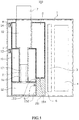
- the E-cigarette 100 includes a housing 1, and a cigarette liquid storing chamber 2, a controlling board 3, a power supply 4, an electric pump 6, an atomization liquid storing chamber 10, an atomizing head 11, and a collecting chamber 12, all of which locates inside the housing 1.
- the E-cigarette 100 further includes a cigarette mouthpiece 7 which extends out of the housing 1.
- a smoke passage 18 is provided in the atomization liquid storing chamber 10.
- the cigarette mouthpiece 7 is mounted on the smoke passage 18 and extends out of the housing 1 from the smoke passage 18.
- the atomizing head 11 is disposed on a bottom of the smoke passage 18, and next to the atomizing head 11, a liquid inlet 16 is arranged, which is in communication with the atomization liquid storing chamber 10 to allow cigarette liquid to flow to an aspiration element 17.
- the cigarette liquid flows via the liquid inlet 16 into the atomizing head 11, where the cigarette liquid is atomized into smoke which is discharged via the smoke passage 18 out of the cigarette mouthpiece 7 for a smoker to smoke.
- the atomizing head 11 also includes an aspiration element 17 and a heating element (not shown) disposed therein.
- the aspiration element 17 wraps the heating element.
- the heating element wraps the aspiration element 17.
- an end of the aspiration element 17 extends into the atomization liquid storing chamber 10 via the liquid inlet 16, so as to draw liquid more effectively.
- the aspiration element 17 is a functional element for adsorbing liquid, such as cotton, fiber ropes and the like, and the heating element is a metal wire such as nichrome and the like.
- FIG. 1 illustrates only the E-cigarette including the aspiration element 17.
- the electric pump 6 can control the cigarette liquid storing chamber 2 and the atomization liquid storing chamber 10, the aspiration element 17 may not be included therein. Instead, the cigarette liquid in the cigarette liquid storing chamber 2 is directly pumped by the electric pump 6 to the atomization liquid storing chamber 10, which is not limited herein.
- the present disclosure further includes a display (not shown), which is mounted on the outer surface of the housing 1, and may particularly be provided on a side surface, a top surface or a bottom surface thereof.
- the display is electrically coupled with the controlling board 3 to display data related to the E-cigarette 100 for viewing.
- the related data that may be shown on the display includes prompting information or E-cigarette parameter information for, e.g., prompting the user to clean the atomization liquid storing chamber 10, prompting the user to refill the atomization liquid storing chamber 10, prompting the user to refill the cigarette liquid storing chamber 2, informing the user that the cigarette liquid storing chamber 2 has been completing refilling, etc.
- the E-cigarette parameter information may include the power voltage, the real-time current, the power setting, the real-time resistance, and the like.
- the present disclosure further includes a cigarette liquid bottle 20, which is provided with a conduit 201 which is retractable into and out of the bottle.
- the cigarette liquid bottle 20 is filled with cigarette liquid that can be used by the E-cigarette 100.
- one of the functions common to the cigarette liquid storing chamber 2, the atomization liquid storing chamber 10 and the collecting chamber 12 is to store the cigarette liquid, and the atomization liquid storing chamber 10 and the collecting chamber 12 are coupled to the electric pump 6.
- the bottom of the housing 1 is provided with a first through hole 151, through which the collecting chamber 12, the atomization liquid storing chamber 10 and the cigarette liquid storing chamber 2 may communicate with a cigarette liquid bottle 20 external to the E-cigarette 100.
- the collecting chamber 12 is located on the bottom of the housing 1, a second through hole 152 is provided at a location where the collecting chamber 12 contacts the electric pump 6, and the electric pump 6 may pump the cigarette liquid in the collecting chamber through the second through hole 152 to other positions; when a third through hole 153 is provided at a location where the atomization liquid storing chamber 10 contacts the electric pump 6, the electric pump 6 may pump the cigarette liquid out from the collecting chamber through the second through hole 152, and then transmit the cigarette liquid pumped out to the atomization liquid storing chamber 10 through the third through hole 153.
- the electric pump 6, similarly to above, may pump the cigarette liquid out from the collecting chamber through the second through hole 152, and then transmit the cigarette liquid pumped out to the cigarette liquid storing chamber 2 through the fourth through hole 154.
- a third through hole 153 is provided at a location where the atomization liquid storing chamber 10 contacts the electric pump 6, and a fourth through hole 154 is provided at a location where the cigarette liquid storing chamber 2 contacts the electric pump 6, at this time, the cigarette liquid in the collecting chamber may be pumped out and transmitted to the atomization liquid storing chamber 10 or the cigarette liquid storing chamber 2, in accordance with the design requirements.
- a first through hole 151 is also provided at the bottom of the housing 1, and the electric pump 6 connects to the first through hole 151, at this time, the electric pump 6 may pump the cigarette liquid out from the collecting chamber 12 through the second through hole 152, and then transmit the cigarette liquid pumped out to external of the E-cigarette.
- the cigarette liquid storing chamber 2 is provided with a fourth through hole 154 at a location where the cigarette liquid storing chamber 2 contacts the electric pump 6.
- the atomization liquid storing chamber 10 is provided with a third through hole 153 at a location where the atomization liquid storing chamber 10 contacts the electric pump 6.
- the cigarette liquid storing chamber 2 is disposed above the collecting chamber 12.
- the atomization liquid storing chamber 10 may be arranged either inside the cigarette liquid storing chamber 2 or side-by-side with the cigarette liquid storing chamber 2.
- the cigarette liquid storing chamber 2 functions as a primary storage for the cigarette liquid and has a chamber with a volume larger than that of the atomization liquid storing chamber 10.
- the collecting chamber 12 is configured to collect condensate liquid flowing down a wall of the atomizing passage 18 and liquid leaking from the aspiration element 17 or leaking from any of the chambers and the passage walls.
- the cigarette liquid storing chamber 2 may be freely detachable, and when it is detached, it may be sealed off with a sealing cap to store the cigarette liquid for a long time.
- the collecting chamber 12 may also be freely detachable.
- the collecting chamber 12 includes a second liquid level detecting component 5.
- the cigarette liquid storing chamber 2 includes a third liquid level detecting component 8 and a second pneumatic pressure controlling component 14.
- the atomization liquid storing chamber 10 includes a first liquid level detecting component 9 and a first pneumatic pressure controlling component 13. Meanwhile, as shown in FIGS. 5 and 6 , the first pneumatic pressure controlling component 13 includes a first pressure relieving valve 131 and a first pneumatic pressure detecting component 132.
- the second pneumatic pressure controlling component 14 includes a second pressure relieving valve 141 and a second pneumatic pressure detecting component 142.
- the power supply 4 is electrically coupled with the electronic components in the E-cigarette 100 for providing power thereto.
- the electronic components include but are not limited to the electric pump 6, the controlling board 3, the first pressure relieving valve 131, the second pressure relieving valve 141, the first liquid level detecting component 9, the second liquid level detecting component 5, the third liquid level detecting component 8, the atomizing head 11, the display, the second pneumatic pressure detecting component 142 and the first pneumatic pressure detecting component 132, etc..
- the electric pump 6 of the disclosure is electrically coupled with the controlling board 3.
- the electric pump 6 When the power supply 4 supplies power, the electric pump 6 is activated, and the controlling board 3 controls the electric pump 6.
- FIG. 7 which is an exemplary structure for the electric pump 6, the electric pump 6 includes a motor 67 and a worm 66 coupled to the motor 67.
- a push rod 64 is mounted on an end of the worm 66.
- the electric pump 6 further includes a guiding rail 65 and a piston 63.
- the push rod 64 is slidable along the guiding rail 65.
- the piston 63 is mounted on an end of the push rod 64, and may be driven by the push rod 64.
- the electric pump 6 shown in FIG. 7 includes a first storing chamber 61 and a second storing chamber 62.
- the motor 67 rotates, and the worm 66 rotates along with the motor 67, driving the push rod 64 to move along the guiding rail 65, and the push rod 64 drives the piston 63 to move forward.
- the piston 63 moves forward, and further pushes the second storing chamber 62 to compress the gas or liquid therein, increasing the internal pressure in the chamber 62, so that the gas or liquid therein is pumped into the first storing chamber 61.
- the piston 63 returns, decreasing the pressure in the second storing chamber 62, so that the gas or liquid in the first storing chamber 61 is drawn into the second storing chamber 62.
- the electric pump 6 is in communication with the cigarette liquid storing chamber 2 and the atomization liquid storing chamber 10.
- the cigarette liquid storing chamber 2 is equivalent to the second storing chamber 62.
- the atomization liquid storing chamber 10 is equivalent to the first storing chamber 61.
- FIG. 7 only shows the case where the electric pump 6 is coupled to two storing chambers, the same principle applies to situations where the electric pump 6 drives three or more storing chambers.
- FIG. 8 which illustrates three storing chambers as an example, a two-position three-way solenoid valve 68 may be provided, through which the electric pump 6 may be configured to communicate with three storing chambers, respectively: for example, when the third through hole 153 is provided at a location where the atomization liquid storing chamber 10 contacts the electric pump 6, and the fourth through hole 154 is provided at a location where the cigarette liquid storing chamber 2 contacts the electric pump 6, communicate with the collecting chamber 12 via the second through hole 152, communicate with the cigarette liquid storing chamber 2 via the fourth through hole 154, and communicate with the atomization liquid storing chamber 10 via the third through hole 153.
- the controlling board 3 may control the pumping action of the pump 6, such as pumping the cigarette liquid in the atomization liquid storing chamber 10 into the cigarette liquid storing chamber 2, or pumping the cigarette liquid in the cigarette liquid storing chamber 2 into the atomization liquid storing chamber 10, or pumping the cigarette liquid in the collecting chamber 12 into the cigarette liquid storing chamber 2 and the like. As shown in FIG.
- a two-position four-way solenoid valve 69 may be provided, through which the electric pump 6 may be configured to communicate with four storing chambers, respectively, for example: communicate with the collecting chamber 12 via the second through holes 152, communicate with the cigarette liquid storing chamber 2 via the fourth through hole 154, communicate with the atomization liquid storing chamber 10 via the third through hole 153, and communicate with any liquid storing apparatus external to the housing 1 via the first through hole 151.
- a liquid storing apparatus external to the housing 1 may be, for example, a cigarette liquid bottle 20.
- the controlling board 3 can control the pumping action for the electric pump 6, such as to pumping the cigarette liquid in the atomization liquid storing chamber 10 into the cigarette liquid storing chamber 2, or pumping the cigarette liquid in the cigarette liquid storing chamber 2 into the atomization liquid storing chamber 10, or pumping the cigarette liquid in the collecting chamber 12 into the cigarette liquid storing chamber 2, and pumping the cigarette liquid in the collecting chamber 12 out of the E-cigarette 100 for the cigarette liquid bottle 20 to collect, and the like.
- the electric pump 6 such as to pumping the cigarette liquid in the atomization liquid storing chamber 10 into the cigarette liquid storing chamber 2, or pumping the cigarette liquid in the cigarette liquid storing chamber 2 into the atomization liquid storing chamber 10, or pumping the cigarette liquid in the collecting chamber 12 into the cigarette liquid storing chamber 2, and pumping the cigarette liquid in the collecting chamber 12 out of the E-cigarette 100 for the cigarette liquid bottle 20 to collect, and the like.
- the electric pump 6 is configured to pump the cigarette liquid in the atomization liquid storing chamber 10 into the cigarette liquid storing chamber 2, and to pump the cigarette liquid in the cigarette liquid storing chamber 2 into the atomization liquid storing chamber 10.
- the electric pump 6 may also pump the cigarette liquid in the collecting chamber 12 into the cigarette liquid storing chamber 2 or out of the E-cigarette 100.
- the controlling board 3 is electrically coupled with the electric pump 6, and is configured to, with power from the power supply 4, control the electric pump 6 to pump the cigarette liquid in the atomization liquid storing chamber 10 into the cigarette liquid storing chamber 2 when the cigarette liquid in the atomization liquid storing chamber 10 needs to be cleared out, or control the electric pump 6 to pump the liquid pump in the cigarette liquid storing chamber 2 into the atomization liquid storing chamber 10 when the cigarette liquid need to be refilled, or control the electric pump 6 to pump the cigarette liquid in the collecting chamber 12 into the cigarette liquid storing chamber 2 or out of the E-cigarette when the cigarette liquid in the collecting chamber reaches a given level.
- the atomizing head 11, electrically coupled with the controlling board 3, is configured to atomize the cigarette liquid entering therein through the liquid inlet 16 from the atomization liquid storing chamber 10 into smoke for a user to smoke.
- the user may use the cigarette mouthpiece 7 to inhale the smoke from the E-cigarette 100.
- the atomization liquid storing chamber 10 is internally provided with a first pressure detecting component 132 and a first pressure relieving valve 131.
- the first pneumatic pressure detecting component 132 and first pressure relieving valve 131 may be arranged on the sidewall of the atomization liquid storing chamber 10 and electrically coupled with the controlling board 3.
- the first pneumatic pressure detecting component 132 is configured to detect the pneumatic pressure in the atomization liquid storing chamber 10 and when it is detected that the pneumatic pressure in the atomization liquid storing chamber 10 reaches a first preset pressure value, the first pressure relieving valve 131 will be activated to relieve pressure for the atomization liquid storing chamber 10.
- a second pneumatic pressure detecting component 142 and a second pressure relieving valve 141 are disposed inside the cigarette liquid storing chamber 2, optionally disposed on the sidewall of the cigarette liquid storing chamber 2, and electrically coupled with the controlling board 3.
- the second pneumatic pressure detecting component 142 is configured to detect the pneumatic pressure in the cigarette liquid storing chamber 2 and when it is detected that the pneumatic pressure in the atomization liquid storing chamber 2 reaches a second preset pressure value, the second pressure relieving valve 141 will be activated to relieve pressure for the cigarette liquid storing chamber 2.
- the second preset pressure value is pre-configured according to a performance of the cigarette liquid storing chamber 2.
- the first liquid level detecting component 9 is disposed in the atomization liquid storing chamber 10, electrically coupled with the controlling board 3, and is configured to detect the liquid level in the atomization liquid storing chamber 10.
- the first liquid level detecting component 9 may be disposed on the bottom, or on a upper portion of a sidewall of the atomization liquid storing chamber 10.
- the first liquid level detecting component 9 disposed on the bottom of the atomization liquid storing chamber 10 is configured to detect a minimum liquid level thereof for determining whether any liquid is in the atomization liquid storing chamber 10.
- the first liquid level detecting component 9 disposed on the upper portion of the sidewall of the atomization liquid storing chamber 10 is configured to detect the maximum liquid level of the atomization liquid storing chamber 10 for determining whether to terminate refilling the atomization liquid storing chamber 10.
- the first liquid level detecting component 9 may also be disposed on a lower portion of the sidewall of the atomization liquid storing chamber 10.
- the specific location on the lower portion of the sidewall for the first liquid level detecting component 9 is determined according to a preset liquid cleaning level for the atomization liquid storing chamber 10.
- the preset liquid cleaning level is configured to define a liquid level that, when the liquid level is reached, the atomization liquid storing chamber 10 needs to be cleaned.
- the preset liquid cleaning level is configured as 10% of a capacity of the atomization liquid storing chamber 10, and the atomization liquid storing chamber 10 will need to be cleaned when the liquid level therein reaches 10% of its capacity.
- the first liquid level detecting component 9 arranged on the lower portion of the sidewall of the atomization liquid storing chamber 10, may detect whether the position of the preset liquid level has been reached.
- first liquid level detecting components 9 there may be more than one of the first liquid level detecting components 9, which are respectively disposed on the bottom, the lower portion of the sidewall or the upper portion of the sidewall, of the atomization liquid storing chamber 10, or any other location where liquid level detecting is desired, in order to detect the particular liquid level in the atomization liquid storing chamber 10 in real time.
- a value measured by the first liquid level detecting component 9 at any specific location may be selected as a first preset liquid level of the atomization liquid storing chamber 10.
- the first liquid level detecting component 9 may be separately arranged on the bottom, the upper portion of the sidewall or the lower portion of the sidewall of the atomization liquid storing chamber 10, or the first liquid level detecting components 9 may be simultaneously arranged on the bottom and the upper portion of the sidewall of the atomization liquid storing chamber 10, or simultaneously arranged on the bottom and the lower portion of the sidewall of the atomization liquid storing chamber 10, or simultaneously arranged on the bottom, the upper portion and the lower portion of the sidewall of the atomization liquid storing chamber 10, the first liquid level detection component being configured to: detect a minimum liquid level of the atomization liquid storing chamber 10 when arranged on the bottom thereof; detect a maximum liquid level of the atomization liquid storing chamber 10 when arranged on the upper portion of the sidewall thereof; and detect a first preset liquid level value for the atomization liquid storing chamber 10 when arranged on the lower portion of the sidewall thereof.
- the controlling board 3 is configured to, after the E-cigarette 100 is activated, pump the cigarette liquid in the cigarette liquid storing chamber 2 into the atomization liquid storing chamber 10 via the fourth through hole 154 and the third through hole 153 as required by actual situation.
- the controlling board 3 may also, following the activation of the E-cigarette 100, control the first liquid level detecting component 9 to detect the liquid level in the atomization liquid storing chamber 10 to determine whether there is any liquid in the atomization liquid storing chamber 10.
- the controlling board 3 controls the electric pump 6 to pump the cigarette liquid from the cigarette liquid storing chamber 2 into the atomization liquid storing chamber 10 via the fourth through hole 154 and third through hole 153, so that the atomization liquid storing chamber 10 get cigarette liquid.
- the controlling board 3 controls the electric pump 6 to terminate pumping cigarette liquid from the cigarette liquid storing chamber 2 into the atomization liquid storing chamber 10.
- any one of the liquid levels detected by the first liquid level detecting component 9 located on the lower portion of the sidewall of or any other location in the atomization liquid storing chamber 10 may be set as the first preset liquid level.
- the controlling board 3 is further configured to control the first liquid level detecting component 9 to detect the liquid level in the atomization liquid storing chamber 10 and determine whether the detected liquid level reaches the first preset liquid level.
- the first liquid level detecting component 9 detects whether the liquid level in the atomization liquid storing chamber 10 reaches the first preset liquid level.
- the controlling board 3 controls the electric pump 6 to terminate pumping of the cigarette liquid from the cigarette liquid storing chamber 2 into the atomization liquid storing chamber 10, i.e., to terminate refilling operation.
- the controlling board 3 will control the electric pump 6 to continue pumping of the cigarette liquid from the cigarette liquid storing chamber 2 into the atomization liquid storing chamber 10.
- the first preset liquid level may be pre-configured by a user to be at, e.g., the maximum liquid level, or 70% to 90% of the maximum liquid level of the liquid storing chamber in the atomization liquid storing chamber 10.
- the first preset liquid level may also be configured according to an output power of the E-cigarette 100.
- the controlling board 3 is further configured to control the first pneumatic pressure detecting component 132 to detect the pneumatic pressure in the atomization liquid storing chamber 10 and determine whether the detected pneumatic pressure reaches the first preset pressure value.
- the controlling board 3 controls the first pressure relieving valve 131 to be activated to relieve the pressure.
- the controlling board 3 continues detecting the pneumatic pressure in the atomization liquid storing chamber 10 and determining whether the liquid level in the atomization liquid storing chamber 10 reaches the first preset liquid level value.
- the first preset pressure value is pre-configured according to the performance of the atomization liquid storing chamber 10.
- the controlling board 3 When there is liquid in the atomization liquid storing chamber 10, the controlling board 3 sends prompting information to the display to prompt the user to clean the atomization liquid storing chamber 10.
- the E-cigarette 100 may also include a vibrating unit (not shown) to prompt the user to clean the atomization liquid storing chamber 10.
- the display may also show a confirmation window for the user to confirm whether to ignore the prompting information.
- the controlling board 3 controls the liquid pump 6 to pump the cigarette liquid in the cigarette liquid storing chamber 2 into the atomization liquid storing chamber 10, and When the user does not ignore the prompting information, the controlling board 3 turns off the E-cigarette 100.
- the third liquid level detecting component 8 is disposed inside the cigarette liquid storing chamber 2, electrically coupled with the controlling board 3, and is configured to detect the liquid level in the cigarette liquid storing chamber 2.
- the third liquid level detecting component 8 may include a liquid level detecting component disposed on the bottom and/or a liquid level detecting component disposed on the upper end of the cigarette liquid storing chamber 2.
- the liquid level detecting component disposed on the bottom of the cigarette liquid storing chamber 2 is configured to detect the minimum liquid level thereof for determining whether there is any liquid in the cigarette liquid storing chamber 2, i.e., whether liquid refilling is necessary.
- the liquid level detecting component arranged on the upper end of the cigarette liquid storing chamber 2 is configured to detect the maximum liquid level of the cigarette liquid storing chamber 2, so as to determine whether to terminate liquid refilling into the cigarette liquid storing chamber 2, i.e., the refilling is completed.
- a conduit 201 on the cigarette liquid bottle 20 is aligned to, and is in fluid communication with the first through hole 151, and the cigarette liquid 202 in the cigarette liquid bottle 20 is injected into the cigarette liquid storing chamber 2 by the electric pump 6.
- the controlling board 3 is configured to control the third liquid level detecting component 8 to detect the liquid level in the cigarette liquid storing chamber 2 after the E-cigarette 100 is activated, and determine whether there is any liquid in the cigarette liquid storing chamber 2, i.e., whether refilling is needed.
- the third liquid level detecting component 8 may include a liquid level detecting component disposed on the bottom and the upper end of the cigarette liquid storing chamber 2.
- the controlling board 3 controls the electric pump 6 to pump the cigarette liquid 202 in the cigarette liquid bottle 20 into the cigarette liquid storing chamber 2 via the conduit 201 and the first through hole 151.
- the controlling board 3 controls the electric pump 6 to terminate refilling the cigarette liquid storing chamber 2, i.e., to completing the refilling.
- the controlling board 3 is further configured to control the second pneumatic pressure detecting component 142 to detect the pneumatic pressure in the cigarette liquid storing chamber 2 and determine whether the detected pneumatic pressure reaches the second preset pressure value.
- the controlling board 3 control the second pressure relieving valve 141 to be activated to relieve pressure for the cigarette liquid storing chamber 2.
- the controlling board 3 is also configured to, when the user desires to smoke, control the atomizing head 11 to transform the cigarette liquid in the atomization liquid storing chamber 10 into smoke for the user to smoke through the cigarette mouthpiece 7.
- the second liquid level detecting component 5 is disposed inside the collecting chamber 12, electrically coupled with the controlling board 3, and is configured to detect the liquid level in the collecting chamber 12.
- the electric pump 6 may be controlled to pump the cigarette liquid from the collecting chamber 12 into the cigarette liquid storing chamber 2 via the second through hole 152 and the fourth through hole 154, or to pump the cigarette liquid from the collecting chamber 12 out of the E-cigarette 100 via the second through hole 152 and the first through hole 151.
- the collecting chamber 12 is detachable, the collecting chamber 12 may be manually detached, so that the cigarette liquid in the collecting chamber 12 may be dumpped.
- the controlling board 3 is further configured to control the second liquid level detecting component 5 to detect the liquid level in the collecting chamber 12 and determine whether the detected liquid level reaches the second predetermined liquid level.
- the controlling board 3 controls the electric pump 6 to pump the cigarette liquid from the collecting chamber 12 into the cigarette liquid storing chamber via the second through hole 152 and the fourth through hole 154 and, or pump the cigarette liquid from the collecting chamber 12 out of the E-cigarette 12 via the second through hole 152 and the first through hole 151, or the controlling board 3 may send prompting information to the display to prompt the user to manually detach the collecting chamber 12 and dump the cigarette liquid contained therein.
- the second preset liquid level may be pre-configured by the user to be at, e.g., the maximum liquid level, or 70% to 90% of the maximum liquid level of the liquid storing chamber in the collecting chamber 12.
- the controlling board 3 is also configured to, after the user terminates smoking, determine whether time elapsed since the last smoking reaches a time value set for returning liquid. When the time elapsed since the termination of atomization last smoking reaches the time value set for returning liquid, the controlling board 3 controls the electric pump 6 to pump the cigarette liquid in the atomization liquid storing chamber 10 into the cigarette liquid storing chamber 2, and controls the electric pump 6 to pump the cigarette liquid in the collecting chamber 12 into the cigarette liquid storing chamber 2 or out of the E-cigarette, or send prompting information to the display to prompt the user to manually detach the collecting chamber 12 and dump the cigarette liquid contained therein.
- the time value set for returning liquid is configured for determining a wait time for the E-cigarette 100 empties the cigarette liquid in the atomization liquid storing chamber 10, and may be pre-configured according to how frequent the user desires to empty. A higher frequency leads to a smaller time value set for returning liquid, and a lower frequency leads to a larger time value set for returning liquid. Assuming that the user desires to empty the cigarette liquid in the atomization liquid storing chamber 10 each time after the E-cigarette 100 is smoked, the time value set for returning liquid may be set to a smaller value, such as a value of 10 minutes, 1 hour and the like.
- the time value set for returning liquid may be set to a large value, such as a value of 12 hours, 24 hours and the like.
- the E-cigarette when the E-cigarette is provided with only the electric pump 6, but neither the aspiration element 17, and the time value set for returning liquid is reached, the cigarette liquid in the atomization liquid storing chamber 10 may be directly pumped into the cigarette liquid storing chamber 2; and when the E-cigarette is provided with the aspiration element 17 together with the electric pump 6, due to the aspiration element 17 may continuously draw the cigarette liquid into the atomization liquid storing chamber 10, the E-cigarette may further be provided with an occlusion component, and uses the occlusion component to block the liquid inlet, in order to avoid the problem of increasing again.
- the controlling board 3 is also configured to control the E-cigarette 100 to be deactivated after the cigarette liquid in the atomization liquid storing chamber 10 is evacuated.
- controlling board 3 controls the pumping actions for the electric pump 6, such as to pump the cigarette liquid in the atomization liquid storing chamber 10 into the cigarette liquid storing chamber 2, or to pump the cigarette liquid in the cigarette liquid storing chamber 2 into the atomization liquid storing chamber 10, to pump the cigarette liquid in the collecting chamber 12 into the cigarette liquid storing chamber 2 or out of the E-cigarette, and the like.
- the controlling board 3 may simultaneously control different pumping actions for the electric pump 6.
- the cleaning apparatus which is the electric pump 6 as an example.
- the cleaning apparatus may also be a manual pump.
- the E-cigarette may further be provided with a conduit communicating with the collecting chamber. After the manual pump is triggered. The liquid smoke in the collecting chamber is discharged through the conduit to the external of the E-cigarette.
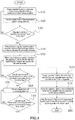
- FIGS. 2 , 3 and 4 are flow charts of a method for controlling cigarette liquid in an E-cigarette according to an embodiment of the present disclosure.
- a controlling board 3 controls an electric pump 6 to pump cigarette liquid in an cigarette liquid storing chamber 2 into an atomization liquid storing chamber 10.
- the method may further include the following steps: the controlling board 3 controls, after the activation of the E-cigarette 100, a first liquid level detecting component 9 to detect a liquid level in the atomization liquid storing chamber 10 to determine whether there is any liquid in an atomization liquid storing chamber 10; when the atomization liquid storing chamber 10 is empty or at its minimum liquid level, the controlling board 3 controls an electric pump 6 to pump cigarette liquid from a cigarette liquid storing chamber 2into the atomization liquid storing chamber 10 via a fourth through hole 154 and a third through hole 153; otherwise, the liquid level in the atomization liquid storing chamber 10 is determined not at its minimum, upon which the controlling board 3 sends prompting information to a display to prompt a user to clean the atomization liquid storing chamber 10; in case the user ignores the prompting information, then instead of cleaning the cigarette liquid from the atomization liquid storing chamber, the controlling board 3 controls the electric pump 6 to pump cigarette liquid from the cigarette
- the method may further include the following steps before Step S10: the controlling board 3, after the E-cigarette is 100 activated, control a third liquid level detecting component 8 on a bottom to detect a liquid level in the cigarette liquid storing chamber 2 to determine whether there is any liquid is in the cigarette liquid storing chamber 2, i.e., whether refilling is needed; in case the liquid storing chamber 2 is at its minimum liquid level or contains no liquid, the controlling board 3 controls the electric pump 6 to pump the cigarette liquid 202 from the cigarette liquid bottle 20 into the cigarette liquid storing chamber 2 via the conduit 201 and the first through hole 151; simultaneously, the controlling board 3 controls the third liquid level detecting unit 8 on an upper end to detect whether the liquid level in the cigarette liquid storing chamber 2 is at a maximum level to determine whether to terminate refilling the cigarette liquid storing chamber 2, i.e., completing the refilling.
- the method may further include the following steps: the controlling board 3 controls a second pneumatic pressure detecting component 142 to detect a pneumatic pressure in the cigarette liquid storing chamber 2, and determines whether the detected pneumatic pressure reaches a second preset pressure value. When the detected pneumatic pressure reaches the second preset pressure value, the controlling board 3 controls the second pressure relieving valve 141 to relieve pressure for the cigarette liquid storing chamber 2.
- the cigarette liquid in the cigarette liquid storing chamber is pumped and transmitted into the atomization liquid storing chamber by an electric pump as an example.
- the cigarette liquid may be directly drawn from the cigarette liquid storing chamber into the atomization liquid storing chamber through the aspiration element. At this time, this step may not be included.
- the controlling board 3 controls a first liquid level detecting component 9 to detect a liquid level in the atomization liquid storing chamber 10.
- Step S30 the controlling board 3 determines whether the liquid level detected by the first liquid level detecting device 9 reaches a first preset liquid level.
- Step S40 is executed, and the controlling board 3 controls the electric pump 6 to terminate pumping of the cigarette liquid from the cigarette liquid storing chamber 2 into the atomization liquid storing chamber 10, i.e., to terminate refilling operation.
- the detected liquid level is at the minimum liquid level value or is yet to reach the first preset liquid level value, return to Step S10, and the controlling board 3 controls the electric pump 6 to continue pumping of the cigarette liquid from the cigarette liquid storing chamber 2 into the atomization liquid storing chamber 10.
- the first preset liquid level may be pre-configured by a user to be at, e.g., the maximum liquid level, or 70% to 90% of the maximum liquid level of the liquid storing chamber in the atomization liquid storing chamber 10.
- the first preset liquid level may also be configured according to an output power of the E-cigarette 100.
- the method may further include the following steps: the controlling board 3 controls a first pneumatic pressure detecting component 132 to detect a pneumatic pressure in the atomization liquid storing chamber 10, and determines whether the detected pneumatic pressure reaches a first preset pressure value. When the detected pneumatic pressure reaches the first preset pressure value, the controlling board 3 control the first pressure relieving valve 131 to be activated to relieve pressure for the atomization liquid storing chamber 10.
- the controlling board 3 continues controlling the first pneumatic pressure detecting component 132 to detect the pneumatic pressure in the atomization liquid storing chamber 10 and controlling the first liquid level detecting component 9 to detect whether the liquid level in the atomization liquid storing chamber 10 reaches the first preset liquid level value.
- the first preset pressure value is pre-configured according to performance of the atomization liquid storing chamber 10.
- Step S50 when the user desires to smoke, i.e., the E-cigarette is activated, the controlling board 3 controls an atomizing head 11 to transform the cigarette liquid in the atomization liquid storing chamber 10 into smoke for the user to smoke through a cigarette mouthpiece 7.
- Step S50 that is, during the process of smoking by the smoker, or during the smoking process of transforming the cigarette liquid in the atomization liquid storing chamber 10 into smoke, the method further include the following steps:
- Step S51 the controlling board 3 controls a second liquid level detecting component 5 to detect a liquid level of a collecting chamber 12;
- Step S52 the controlling board 3 determines whether the detected liquid level reaches a second preset liquid level value; and when the detected liquid level reaches the second preset liquid level, Step S53 is started, and the controlling board 3 controls the electric pump 6 to pump cigarette liquid from the collecting chamber 12 into the cigarette liquid storing chamber 2 via the second through hole 152 and the fourth through hole 154, or to pump cigarette liquid from the collecting chamber 12 out of the E-cigarette 100 via the second through hole 152 and the first through hole 151, or the controlling board 3 sends prompting information to a display to prompt the user to manually detach the collecting chamber 12 and to dump the cigarette liquid contained therein.
- the second preset liquid level may be pre-configured by the user to be at, e.g., the maximum liquid level, or 70% to 90% of the maximum liquid level of the liquid storing chamber in the collecting chamber 12. Otherwise, if the detected liquid level has yet to reach the second preset liquid level, the process returns to Step S51.
- Step S60 after termination of atomization at the E-cigarette, the controlling board 3 determines whether time elapsed since the termination of atomization reaches a time value set for returning liquid. When the time elapsed since the termination of atomization reaches the time value set for returning liquid, Step S70 is carried out, and the controlling board 3 controls the electric pump 6 to pump the cigarette liquid from the atomization liquid storing chamber 10 into the cigarette liquid storing chamber 2, and controls the electric pump 6 to pump the cigarette liquid from the collecting chamber 12 into the cigarette liquid storing chamber 2 or to pump the cigarette liquid from the collecting chamber 12 out of the E-cigarette, or sends prompting information to a display to prompt the user to manually detach the collecting chamber 12 and to dump the cigarette liquid contained therein.
- the process returns to the Step S50, and the controlling board 3, when the user desires to smoke, controls an atomizing head 11 to transform the cigarette liquid in the atomization liquid storing chamber 10 into smoke for the user to smoke through the cigarette mouthpiece 7.
- the time value set for returning liquid is configured to determine a wait time before the E-cigarette 100 empties the cigarette liquid in the atomization liquid storing chamber 10, and may be pre-configured according to how frequent the user desires to empty. A higher frequency leads to a smaller time value set for returning liquid, and a lower frequency leads to a larger time value set for returning liquid.
- the time value set for returning liquid may be set to a smaller value, such as a value of 10 minutes, 1 hour and the like.
- the time value set for returning liquid may be set to a larger value, such as a value of 12 hours, 24 hours and the like.
- Step S70 Before Step S70, as shown in FIG. 3 , or after Step S70, as shown in FIG. 4 , the method may further include the following steps:
- Step S51 the controlling board 3 controls a second liquid level detecting component 5 to detect a liquid level of a collecting chamber 12;
- Step S52 the controlling board 3 determines whether the detected liquid level reaches a second preset liquid level value; and when the detected liquid level reaches the second preset liquid level, Step S53 is started, and the controlling board 3 controls the electric pump 6 to pump cigarette liquid from the collecting chamber 12 into the cigarette liquid storing chamber 2 via the second through hole 152 and the fourth through hole 154, or to pump cigarette liquid from the collecting chamber 12 out of the E-cigarette 100 via the second through hole 152 and the first through hole 151, or the controlling board 3 sends prompting information to a display to prompt the user to manually detach the collecting chamber 12 and to dump the cigarette liquid contained therein.
- the second preset liquid level may be pre-configured by the user to be at, e.g., the maximum liquid level, or 70% to 90% of the maximum liquid level of the liquid storing chamber in the collecting chamber 12. Otherwise, if the detected liquid level has yet to reach the second preset liquid level, the process returns to Step S51.
- Step S80 the controlling board 3 controls the E-cigarette 100 to be deactivated after the cigarette liquid in the atomization liquid storing chamber 10 is evacuated.
- step S20 and step S30 may be replaced with:
- the cigarette liquid in the collecting chamber After obtaining the time difference, it detects whether the obtained time difference reaches a preset time difference, and if the preset time difference is a time difference preconfigured according to the leakage speed and the volume of the collecting chamber, it indicates that it has accumulate much cigarette liquid in the collecting chamber when the obtained time difference reaches the preset time difference, and in order to avoid overflow of the cigarette liquid in the collecting chamber, the cigarette liquid in the collecting chamber may be cleaned.
- the time difference is a time difference preconfigured according to the shelf life of the cigarette liquid, it indicates that the cigarette liquid in the collecting chamber has expired, when the obtained cigarette liquid reaches the preset time difference, at this time, the cigarette liquid in the collecting chamber can be cleaned, and the cleaning at this time may be to discharge the cigarette liquid in the collecting chamber to the external, or to prompt the replacement of the collecting chamber.
- the E-cigarette may also clean the collecting chamber at a preset moment after that the preset time difference is reached. For example, when it detects that the time difference obtained reaches the preset time difference at the startup of the E-cigarette, the cleaning may be done at the end of this suction, or at the next startup of the E-cigarette, or at the end of next suction after the next startup, which is not limited herein.
- the above embodiments is only exemplified by pumping the cigarette liquid to the atomization liquid storing chamber or pumping the cigarette liquid to external of the E-cigarette.
- the cleaning may be reminded by way of sending prompting information, which is used to remind of the replacement of the collecting chamber.
Landscapes
- Electrostatic Spraying Apparatus (AREA)
Abstract
Description
- The present disclosure relates to the field of smoking-simulating technology, and particularly to an E-cigarette and a method for controlling cigarette liquid therein.
- E-cigarette, also known as electronic cigarettes, provides smokers with a substitute for smoking. E-cigarette is a smoking device without open fire that usually includes a battery-powered atomizing device to atomize liquid nicotine or nicotine substitutes when activated by a user. Usually, when a user simulates a smoking action by inhaling on the E-cigarette, a controller will automatically activate the atomizing device.
- However, the E-cigarette atomizing device is prone to leakage in use, which is primarily caused by the condensation and prolonged penetration of cigarette liquid. When the cigarette liquid of the E-cigarette is atomized, an aerogel will be generated. When such aerogel at a higher temperature passes through a smoke channel at a lower temperature, the aerogel will, due to heat transfer based on the convective heat-exchange principle, rapidly cool off and condense into cigarette liquid on the inner wall of the smoke passage before flowing out of the smoke passage. The condensed cigarette liquid will adhere onto the inner wall of the atomizing chamber. After long-term use, cigarette liquid droplets accumulate too many, which leads to liquid leakage. In addition, when the E-cigarette is not in use, the cigarette liquid may leak along the aspiration element due to the infiltration of cigarette liquid, keep at the bottom of the atomizing head due to gravity, or spill out of the gas inlet, and then liquid leakage is caused.
- The present disclosure aims at drawbacks in the prior art. A technical problem that is solved by the present disclosure lies in that an E-cigarette is provided, which can effectively prevent the cigarette liquid in the E-cigarette from leaking out therefrom.
- Another technical problem that is solved by the present disclosure lies in that a method for controlling cigarette liquid in an E-cigarette is provided, which can realize the control on cigarette liquid flowing in and out and the control on cigarette liquid storage for the E-cigarette, while effectively prevents the cigarette liquid in the E-cigarette from leaking out therefrom.
- In order to solve the above technical problems, a technical solution adopted by the present disclosure lies in providing an E-cigarette including a housing, an atomization liquid storing chamber inside the housing and a controlling board, the atomization liquid storing chamber is configured to store cigarette liquid, where:
the E-cigarette further comprises a collecting chamber configured to collect leaked cigarette liquid in the E-cigarette, and a cleaning apparatus, wherein the cleaning apparatus is configured to clean the cigarette liquid in the collecting chamber. - Optionally, the cleaning apparatus including an electric pump electrically coupled to the controlling board, and the electric pump is controlled by the controlling board to clean the cigarette liquid in the collecting chamber.
- Optionally, the collecting chamber is provided with a second through hole, the atomization liquid storing chamber is provided with a third through hole, and the electric pump is configured to be in communication with the collecting chamber through the second through hole, and to be in communication with the atomization liquid storing chamber through the third through hole.
- Optionally, a bottom of the housing is provided with a first through hole, the collecting chamber is provided with a second through hole, and the electric pump is configured to be in communication with the collecting chamber through the second through hole, and to be in communication with the external of the E-cigarette through the first through hole.
- Optionally, the collecting chamber is internally provided with a second liquid level detecting component which is electrically coupled with the controlling board and configured to detect a liquid level in the collecting chamber.
- Optionally, the atomization liquid storing chamber is internally provided with a first liquid level detecting component which is electrically coupled with the controlling board, the first liquid level detecting component is arranged on any one of or any combination of: a bottom of the atomization liquid storing chamber, a upper portion of the sidewall of the atomization liquid storing chamber and a lower portion of the sidewall of the atomization liquid storing chamber, the first liquid level detection component being configured to: detect a minimum liquid level of the atomization liquid storing chamber if arranged on the bottom thereof, detect a maximum liquid level of the atomization liquid storing chamber if arranged on the upper portion of the sidewall thereof, and detect a first preset liquid level value for the atomization liquid storing chamber if arranged on the lower portion of the sidewall thereof, where the first preset liquid level value is 70% - 90% of the maximum liquid level of a liquid storing chamber in the atomization liquid storing chamber.
- Optionally, the atomization liquid storing chamber is internally provided with a first pneumatic pressure controlling component which is electrically coupled to the controlling board, the first pneumatic pressure controlling component includes a first pressure relieving valve and a first pneumatic pressure detecting component configured to detect a pneumatic pressure in the atomization liquid storing chamber, and the first pressure relieving valve is configured to relieve pressure for the atomization liquid storing chamber when the pneumatic pressure in the atomization liquid storing chamber reaches a first preset pressure value.
- Optionally, the E-cigarette further includes a cigarette liquid storing chamber, and the cigarette liquid storing chamber is internally provided with a third liquid level detecting component which is electrically coupled with the controlling board, the third liquid level detecting component includes a liquid level detecting component configured to detect a minimum liquid level of the cigarette liquid storing chamber; and/or configured to detect a maximum liquid level of the cigarette liquid storing chamber; and
the cigarette liquid storing chamber is further provided internally with a second pneumatic pressure controlling component which is electrically coupled with the controlling board and the second pneumatic pressure controlling component includes a second pneumatic pressure detecting component configured to detect a pneumatic pressure for the cigarette liquid storing chamber and a second pressure relieving valve configured to relieve pressure for the cigarette liquid storing chamber when the pneumatic pressure in the cigarette liquid storing chamber reaches a second preset pressure value. - Optionally, the E-cigarette further includes a cigarette liquid storing chamber, and the collecting chamber is located on the bottom of the housing, the atomization liquid storing chamber and the cigarette liquid storing chamber are located above the collecting chamber, the atomization liquid storing chamber is located inside the cigarette liquid storing chamber, or the atomization liquid storing chamber is located in parallel with the cigarette liquid storing chamber; and the collecting chamber or the cigarette liquid storing chamber is detachably disposed with respect to the E-cigarette.
- Optionally, the E-cigarette further includes: a cigarette mouthpiece, and a smoke passage arranged in the atomization liquid storing chamber, where the cigarette mouthpiece is mounted on the smoke passage and extends out of the housing from the smoke passage, the smoke passage is provided an atomizing head with a liquid inlet through which the cigarette liquid in the atomization liquid storing chamber flows into the atomizing head via the liquid inlet.
- In order to solve the above technical problems, another technical solution adopted by the present disclosure lies in providing a method for controlling cigarette liquid in an E-cigarette, which includes the following steps:
- detecting whether a cleaning condition for cleaning cigarette liquid in a collecting chamber is satisfied, wherein the collecting chamber is configured to collect leaked cigarette liquid in the E-cigarette; and
- when the cleaning condition is satisfied, cleaning the cigarette liquid in the collecting chamber.
- Optionally, the detecting whether a cleaning condition for cleaning cigarette liquid in the collecting chamber is satisfied, includes:
- obtaining a liquid level in the collecting chamber; and
- detecting whether the liquid level reaches a preset threshold.
- Optionally, the detecting whether a cleaning condition for cleaning cigarette liquid in a collecting chamber is satisfied, includes:
- obtaining a time difference from the last cleaning of the collection chamber; and
- detecting whether the time difference from the last cleaning of the collection chamber reaches a preset time difference.
- Optionally, the when the cleaning condition is satisfied, cleaning the cigarette liquid in the collecting chamber, includes:
when the time difference from the last cleaning of the collection chamber reaches a preset time difference, cleaning the cigarette liquid in the collection chamber at a preset moment thereafter, where the preset moment is a moment of an end of an suction or a moment of a next startup. - Optionally, the cleaning the cigarette liquid in the collecting chamber, includes:
- pumping the cigarette liquid in the collecting chamber into an atomization liquid storing chamber;
- or,
- pumping the cigarette liquid in the collecting chamber out of the E-cigarette;
- or,
- sending prompting information, wherein the prompting information is configured to prompt a change of the collecting chamber.
- Optionally, the method further includes:
- pumping cigarette liquid in the cigarette liquid storing chamber into the atomization liquid storing chamber;
- detecting a liquid level in the atomization liquid storing chamber;
- determining whether the detected liquid level reaches a first preset liquid level value; and
- when the detected liquid level reaches the first preset liquid level value, terminating the pumping of the cigarette liquid in the cigarette liquid storing chamber into the atomization liquid storing chamber.
- Optionally, the method further includes:
- detecting whether the liquid level in the atomization liquid storing chamber is lower than a minimum liquid level, and
- when the detecting result indicates that the atomization liquid storing chamber is lower than a minimum liquid level, controlling an electric pump to pump the cigarette liquid in the cigarette liquid storing chamber into the atomization liquid storing chamber; otherwise when the detecting result indicates that the atomization liquid storing chamber is not lower than the minimum liquid level, sending, by an controlling board, prompting information to a display to prompt a user to clean the atomization liquid storing chamber; or
- when the prompting information is ignored, then instead of cleaning the cigarette liquid from the atomization liquid storing chamber, controlling, by the controlling board, the electric pump to pump the cigarette liquid in the cigarette liquid storing chamber into the atomization liquid storing chamber; otherwise when the prompting information is not ignored, deactivating, by the controlling board, the E-cigarette, and pumping the cigarette liquid in the atomization liquid storing chamber into the cigarette liquid storing chamber;
- detecting a liquid level in the cigarette liquid storing chamber;
- when the liquid level in the cigarette liquid storing chamber is determined to be lower than a minimum liquid level, controlling, by the controlling board, the electric pump to pump cigarette liquid into the cigarette liquid storing chamber; or
- when the liquid level in the cigarette liquid storing chamber is determined to be at the maximum liquid level, controlling, by the controlling board, the electric pump to stop pumping cigarette liquid into the cigarette liquid storing chamber.
- Optionally, the method further includes:
- detecting pneumatic pressure in the cigarette liquid storing chamber and determining whether the detected pneumatic pressure reaches a second preset pressure value; and
- relieving pressure for the cigarette liquid storing chamber when the detected pneumatic pressure reaches the second preset pressure value.
- Optionally, the method further includes:
- detecting pneumatic pressure in the atomization liquid storing chamber and determining whether the detected pneumatic pressure reaches a first preset pressure value; and
- relieving pressure for the atomization liquid storing chamber when the detected pneumatic pressure reaches the first preset pressure value; and
- continuing the detecting of the pneumatic pressure in the atomization liquid storing chamber and the determining of whether the liquid level in the atomization liquid storing chamber reaches the first preset liquid level value, when the detected pneumatic pressure is yet to reach the first preset pressure value.
- An E-cigarette according to the present disclosure is provided with a collecting chamber for collecting the condensate sliding down the wall of the atomizing passage and the cigarette liquid leaking from the aspiration element. Moreover, the method for controlling cigarette liquid provided by the present disclosure can exercise detection and control over the cigarette liquid moving into and out of, as well as the liquid level of, the collecting chamber, so that when the cigarette liquid in the collecting chamber reaches a given level, an electric pump will be controlled to pump the cigarette liquid in the collecting chamber into a cigarette liquid storing chamber or out of the E-cigarette, thereby effectively reducing the leakage of cigarette liquid, and extending the service life of the E-cigarette.
-
-
FIG. 1 is a schematic structural diagram of an E-cigarette according to an embodiment of the present disclosure; -
FIG. 2 is a schematic flow chart of a method for controlling cigarette liquid in an E-cigarette according to an embodiment of the present disclosure; -
FIG. 3 is a schematic flow chart of a method for controlling cigarette liquid in an E-cigarette according to another embodiment of the present disclosure; -
FIG. 4 is a schematic flow chart of a method for controlling cigarette liquid in an E-cigarette according to yet another embodiment of the present disclosure; -
FIG. 5 is a schematic structural diagram of a first pneumatic pressure controlling component as shown inFIG. 1 of the present disclosure; -
FIG. 6 is a schematic structural diagram of a second pneumatic pressure controlling component as shown inFIG. 1 of the present disclosure; -
FIG. 7 is a schematic structural diagram of a first embodiment of an exemplary electric pump as shown inFIG. 1 of the present disclosure; -
FIG. 8 is a schematic structural diagram of a second embodiment of an exemplary electric pump as shown inFIG. 1 of the present disclosure; -
FIG. 9 is a schematic structural diagram of a third embodiment of an exemplary electric pump as shown inFIG. 1 of the present disclosure; and -
FIG. 10 is a schematic structural diagram of an exemplary cigarette liquid bottle according to an embodiment of the present disclosure. - The following specifical implementations will further explain the present disclosure in conjunction with the above drawings.
- The disclosure will be described in detail hereunder in conjuncture with the embodiments shown the drawings. However, these embodiments are not intended to limit the present disclosure, and any alteration to the structure or function made by those skilled in the art according to these embodiments shall be included in the protection scope of the present disclosure.
- Embodiments of the present disclosure provides an E-cigarette, which includes a housing, an atomization liquid storing chamber inside the housing, a cleaning apparatus, a controlling board and a collecting chamber, where the atomization liquid storing chamber is configured to store cigarette liquid, and the collecting chamber configured to collect leaked cigarette liquid in the E-cigarette.
- The atomization liquid storing chamber refers to a chamber which is close to a heating element and is configured to store cigarette liquid. Optionally, a cigarette liquid storing chamber is further included in the E-cigarette, and the cigarette liquid storing chamber refers to a chamber for storing a certain quantity of cigarette liquid in the E-cigarette, where the cigarette liquid storing chamber may be configured to provide liquid to the atomization liquid storing chamber. With both the atomization liquid storing chamber and the cigarette liquid storing chamber arranged simultaneously, the capacity of the cigarette liquid that can be accommodated in the E-cigarette may be increased, which extends the use time after one injection. In the following embodiments, unless otherwise specified, the E-cigarette including both the atomization liquid storing chamber and the cigarette liquid storing chamber simultaneously is taken as examples.
- The collecting chamber is arranged under the atomization liquid storing chamber, and an opening is arranged in a side of the collecting chamber close to the atomization liquid storing chamber, and is configured to accommodate cigarette liquid leaked from the atomization liquid storing chamber.
- The cleaning apparatus is configured to clean the cigarette liquid in the collecting chamber. In practical implementation, the cleaning apparatus may be electric, such as an electric pump, or manual, such as a manual pump. In the following, two cases are separately described.
- Referring to
FIG. 1 , a schematic structural diagram of an E-cigarette according to a preferred embodiment of the present disclosure is shown. The E-cigarette is configured to realize controlling over the cigarette liquid. The cleaning apparatus which is an electric pump is taken as an example in the present embodiment. TheE-cigarette 100 includes ahousing 1, and a cigaretteliquid storing chamber 2, a controllingboard 3, apower supply 4, anelectric pump 6, an atomizationliquid storing chamber 10, an atomizinghead 11, and a collectingchamber 12, all of which locates inside thehousing 1. The E-cigarette 100 further includes acigarette mouthpiece 7 which extends out of thehousing 1. - In this embodiment, a
smoke passage 18 is provided in the atomizationliquid storing chamber 10. Thecigarette mouthpiece 7 is mounted on thesmoke passage 18 and extends out of thehousing 1 from thesmoke passage 18. The atomizinghead 11 is disposed on a bottom of thesmoke passage 18, and next to theatomizing head 11, aliquid inlet 16 is arranged, which is in communication with the atomizationliquid storing chamber 10 to allow cigarette liquid to flow to anaspiration element 17. The cigarette liquid flows via theliquid inlet 16 into the atomizinghead 11, where the cigarette liquid is atomized into smoke which is discharged via thesmoke passage 18 out of thecigarette mouthpiece 7 for a smoker to smoke. Further, the atomizinghead 11 also includes anaspiration element 17 and a heating element (not shown) disposed therein. In an embodiment, theaspiration element 17 wraps the heating element. In another embodiment, the heating element wraps theaspiration element 17. Optionally, an end of theaspiration element 17 extends into the atomizationliquid storing chamber 10 via theliquid inlet 16, so as to draw liquid more effectively. Optionally, theaspiration element 17 is a functional element for adsorbing liquid, such as cotton, fiber ropes and the like, and the heating element is a metal wire such as nichrome and the like. Optionally,FIG. 1 illustrates only the E-cigarette including theaspiration element 17. Optionally, in practical implementation, if theelectric pump 6 can control the cigaretteliquid storing chamber 2 and the atomizationliquid storing chamber 10, theaspiration element 17 may not be included therein. Instead, the cigarette liquid in the cigaretteliquid storing chamber 2 is directly pumped by theelectric pump 6 to the atomizationliquid storing chamber 10, which is not limited herein. - The present disclosure further includes a display (not shown), which is mounted on the outer surface of the
housing 1, and may particularly be provided on a side surface, a top surface or a bottom surface thereof. The display is electrically coupled with the controllingboard 3 to display data related to theE-cigarette 100 for viewing. The related data that may be shown on the display includes prompting information or E-cigarette parameter information for, e.g., prompting the user to clean the atomizationliquid storing chamber 10, prompting the user to refill the atomizationliquid storing chamber 10, prompting the user to refill the cigaretteliquid storing chamber 2, informing the user that the cigaretteliquid storing chamber 2 has been completing refilling, etc.. and the E-cigarette parameter information may include the power voltage, the real-time current, the power setting, the real-time resistance, and the like. - As shown in
FIG. 10 , the present disclosure further includes a cigaretteliquid bottle 20, which is provided with aconduit 201 which is retractable into and out of the bottle. The cigaretteliquid bottle 20 is filled with cigarette liquid that can be used by theE-cigarette 100. - As shown in
FIG. 1 , one of the functions common to the cigaretteliquid storing chamber 2, the atomizationliquid storing chamber 10 and the collectingchamber 12 is to store the cigarette liquid, and the atomizationliquid storing chamber 10 and the collectingchamber 12 are coupled to theelectric pump 6. The bottom of thehousing 1 is provided with a first throughhole 151, through which the collectingchamber 12, the atomizationliquid storing chamber 10 and the cigaretteliquid storing chamber 2 may communicate with a cigaretteliquid bottle 20 external to theE-cigarette 100. The collectingchamber 12 is located on the bottom of thehousing 1, a second throughhole 152 is provided at a location where the collectingchamber 12 contacts theelectric pump 6, and theelectric pump 6 may pump the cigarette liquid in the collecting chamber through the second throughhole 152 to other positions; when a third throughhole 153 is provided at a location where the atomizationliquid storing chamber 10 contacts theelectric pump 6, theelectric pump 6 may pump the cigarette liquid out from the collecting chamber through the second throughhole 152, and then transmit the cigarette liquid pumped out to the atomizationliquid storing chamber 10 through the third throughhole 153. Optionally, when a fourth throughhole 154 is provided at a location where the cigaretteliquid storing chamber 2 contacts theelectric pump 6, theelectric pump 6, similarly to above, may pump the cigarette liquid out from the collecting chamber through the second throughhole 152, and then transmit the cigarette liquid pumped out to the cigaretteliquid storing chamber 2 through the fourth throughhole 154. Of course, in practical implementation, a third throughhole 153 is provided at a location where the atomizationliquid storing chamber 10 contacts theelectric pump 6, and a fourth throughhole 154 is provided at a location where the cigaretteliquid storing chamber 2 contacts theelectric pump 6, at this time, the cigarette liquid in the collecting chamber may be pumped out and transmitted to the atomizationliquid storing chamber 10 or the cigaretteliquid storing chamber 2, in accordance with the design requirements. - Optionally, when a second through
hole 152 is provided at a location where the collectingchamber 12 contacts theelectric pump 6, a first throughhole 151 is also provided at the bottom of thehousing 1, and theelectric pump 6 connects to the first throughhole 151, at this time, theelectric pump 6 may pump the cigarette liquid out from the collectingchamber 12 through the second throughhole 152, and then transmit the cigarette liquid pumped out to external of the E-cigarette. - The cigarette
liquid storing chamber 2 is provided with a fourth throughhole 154 at a location where the cigaretteliquid storing chamber 2 contacts theelectric pump 6. The atomizationliquid storing chamber 10 is provided with a third throughhole 153 at a location where the atomizationliquid storing chamber 10 contacts theelectric pump 6. - In this embodiment, the cigarette
liquid storing chamber 2 is disposed above the collectingchamber 12. The atomizationliquid storing chamber 10 may be arranged either inside the cigaretteliquid storing chamber 2 or side-by-side with the cigaretteliquid storing chamber 2. Optionally, the cigaretteliquid storing chamber 2 functions as a primary storage for the cigarette liquid and has a chamber with a volume larger than that of the atomizationliquid storing chamber 10. The collectingchamber 12 is configured to collect condensate liquid flowing down a wall of theatomizing passage 18 and liquid leaking from theaspiration element 17 or leaking from any of the chambers and the passage walls. Optionally, the cigaretteliquid storing chamber 2 may be freely detachable, and when it is detached, it may be sealed off with a sealing cap to store the cigarette liquid for a long time. Optionally, the collectingchamber 12 may also be freely detachable. - The collecting
chamber 12 includes a second liquidlevel detecting component 5. The cigaretteliquid storing chamber 2 includes a third liquidlevel detecting component 8 and a second pneumaticpressure controlling component 14. The atomizationliquid storing chamber 10 includes a first liquidlevel detecting component 9 and a first pneumaticpressure controlling component 13. Meanwhile, as shown inFIGS. 5 and 6 , the first pneumaticpressure controlling component 13 includes a firstpressure relieving valve 131 and a first pneumaticpressure detecting component 132. The second pneumaticpressure controlling component 14 includes a secondpressure relieving valve 141 and a second pneumaticpressure detecting component 142. - The
power supply 4 is electrically coupled with the electronic components in theE-cigarette 100 for providing power thereto. The electronic components include but are not limited to theelectric pump 6, the controllingboard 3, the firstpressure relieving valve 131, the secondpressure relieving valve 141, the first liquidlevel detecting component 9, the second liquidlevel detecting component 5, the third liquidlevel detecting component 8, the atomizinghead 11, the display, the second pneumaticpressure detecting component 142 and the first pneumaticpressure detecting component 132, etc.. - The
electric pump 6 of the disclosure is electrically coupled with the controllingboard 3. When thepower supply 4 supplies power, theelectric pump 6 is activated, and the controllingboard 3 controls theelectric pump 6. Referring toFIG. 7 , which is an exemplary structure for theelectric pump 6, theelectric pump 6 includes amotor 67 and aworm 66 coupled to themotor 67. Apush rod 64 is mounted on an end of theworm 66. Theelectric pump 6 further includes a guidingrail 65 and apiston 63. Thepush rod 64 is slidable along the guidingrail 65. Thepiston 63 is mounted on an end of thepush rod 64, and may be driven by thepush rod 64. Theelectric pump 6 shown inFIG. 7 includes afirst storing chamber 61 and asecond storing chamber 62. During operation, themotor 67 rotates, and theworm 66 rotates along with themotor 67, driving thepush rod 64 to move along the guidingrail 65, and thepush rod 64 drives thepiston 63 to move forward. When themotor 67 rotates in a positive direction, thepiston 63 moves forward, and further pushes thesecond storing chamber 62 to compress the gas or liquid therein, increasing the internal pressure in thechamber 62, so that the gas or liquid therein is pumped into thefirst storing chamber 61. When themotor 67 rotates in a reverse direction, thepiston 63 returns, decreasing the pressure in thesecond storing chamber 62, so that the gas or liquid in thefirst storing chamber 61 is drawn into thesecond storing chamber 62. As shown in the present disclosure, theelectric pump 6 is in communication with the cigaretteliquid storing chamber 2 and the atomizationliquid storing chamber 10. The cigaretteliquid storing chamber 2 is equivalent to thesecond storing chamber 62. The atomizationliquid storing chamber 10 is equivalent to thefirst storing chamber 61. When themotor 67 rotates in the positive direction, the cigarette liquid in theliquid storing chamber 2 is pumped into the atomizationliquid storing chamber 10, and when themotor 67 rotates in the reverse direction, thepiston 63 returns, and the cigarette liquid in theliquid storing chamber 10 is drawn into the cigaretteliquid storing chamber 2. - It should be noted that,
FIG. 7 only shows the case where theelectric pump 6 is coupled to two storing chambers, the same principle applies to situations where theelectric pump 6 drives three or more storing chambers. As shown inFIG. 8 , which illustrates three storing chambers as an example, a two-position three-way solenoid valve 68 may be provided, through which theelectric pump 6 may be configured to communicate with three storing chambers, respectively: for example, when the third throughhole 153 is provided at a location where the atomizationliquid storing chamber 10 contacts theelectric pump 6, and the fourth throughhole 154 is provided at a location where the cigaretteliquid storing chamber 2 contacts theelectric pump 6, communicate with the collectingchamber 12 via the second throughhole 152, communicate with the cigaretteliquid storing chamber 2 via the fourth throughhole 154, and communicate with the atomizationliquid storing chamber 10 via the third throughhole 153. The controllingboard 3 may control the pumping action of thepump 6, such as pumping the cigarette liquid in the atomizationliquid storing chamber 10 into the cigaretteliquid storing chamber 2, or pumping the cigarette liquid in the cigaretteliquid storing chamber 2 into the atomizationliquid storing chamber 10, or pumping the cigarette liquid in the collectingchamber 12 into the cigaretteliquid storing chamber 2 and the like. As shown inFIG. 9 , which illustrates four storing chambers as an example, a two-position four-way solenoid valve 69 may be provided, through which theelectric pump 6 may be configured to communicate with four storing chambers, respectively, for example: communicate with the collectingchamber 12 via the second throughholes 152, communicate with the cigaretteliquid storing chamber 2 via the fourth throughhole 154, communicate with the atomizationliquid storing chamber 10 via the third throughhole 153, and communicate with any liquid storing apparatus external to thehousing 1 via the first throughhole 151. Such a liquid storing apparatus external to thehousing 1 may be, for example, a cigaretteliquid bottle 20. The controllingboard 3 can control the pumping action for theelectric pump 6, such as to pumping the cigarette liquid in the atomizationliquid storing chamber 10 into the cigaretteliquid storing chamber 2, or pumping the cigarette liquid in the cigaretteliquid storing chamber 2 into the atomizationliquid storing chamber 10, or pumping the cigarette liquid in the collectingchamber 12 into the cigaretteliquid storing chamber 2, and pumping the cigarette liquid in the collectingchamber 12 out of the E-cigarette 100 for the cigaretteliquid bottle 20 to collect, and the like. - The
electric pump 6 is configured to pump the cigarette liquid in the atomizationliquid storing chamber 10 into the cigaretteliquid storing chamber 2, and to pump the cigarette liquid in the cigaretteliquid storing chamber 2 into the atomizationliquid storing chamber 10. Theelectric pump 6 may also pump the cigarette liquid in the collectingchamber 12 into the cigaretteliquid storing chamber 2 or out of theE-cigarette 100. Specifically, the controllingboard 3 is electrically coupled with theelectric pump 6, and is configured to, with power from thepower supply 4, control theelectric pump 6 to pump the cigarette liquid in the atomizationliquid storing chamber 10 into the cigaretteliquid storing chamber 2 when the cigarette liquid in the atomizationliquid storing chamber 10 needs to be cleared out, or control theelectric pump 6 to pump the liquid pump in the cigaretteliquid storing chamber 2 into the atomizationliquid storing chamber 10 when the cigarette liquid need to be refilled, or control theelectric pump 6 to pump the cigarette liquid in the collectingchamber 12 into the cigaretteliquid storing chamber 2 or out of the E-cigarette when the cigarette liquid in the collecting chamber reaches a given level. The atomizinghead 11, electrically coupled with the controllingboard 3, is configured to atomize the cigarette liquid entering therein through theliquid inlet 16 from the atomizationliquid storing chamber 10 into smoke for a user to smoke. The user may use thecigarette mouthpiece 7 to inhale the smoke from theE-cigarette 100. - Referring to
FIGS. 5 and 6 , for the purpose of detecting and adjusting the pneumatic pressure in the atomizationliquid storing chamber 10, the atomizationliquid storing chamber 10 is internally provided with a firstpressure detecting component 132 and a firstpressure relieving valve 131. Optionally, the first pneumaticpressure detecting component 132 and firstpressure relieving valve 131 may be arranged on the sidewall of the atomizationliquid storing chamber 10 and electrically coupled with the controllingboard 3. The first pneumaticpressure detecting component 132 is configured to detect the pneumatic pressure in the atomizationliquid storing chamber 10 and when it is detected that the pneumatic pressure in the atomizationliquid storing chamber 10 reaches a first preset pressure value, the firstpressure relieving valve 131 will be activated to relieve pressure for the atomizationliquid storing chamber 10. - In order to detect and adjust the pneumatic pressure in the cigarette
liquid storing chamber 2, a second pneumaticpressure detecting component 142 and a secondpressure relieving valve 141 are disposed inside the cigaretteliquid storing chamber 2, optionally disposed on the sidewall of the cigaretteliquid storing chamber 2, and electrically coupled with the controllingboard 3. The second pneumaticpressure detecting component 142 is configured to detect the pneumatic pressure in the cigaretteliquid storing chamber 2 and when it is detected that the pneumatic pressure in the atomizationliquid storing chamber 2 reaches a second preset pressure value, the secondpressure relieving valve 141 will be activated to relieve pressure for the cigaretteliquid storing chamber 2. The second preset pressure value is pre-configured according to a performance of the cigaretteliquid storing chamber 2. - The first liquid
level detecting component 9 is disposed in the atomizationliquid storing chamber 10, electrically coupled with the controllingboard 3, and is configured to detect the liquid level in the atomizationliquid storing chamber 10. In this embodiment, the first liquidlevel detecting component 9 may be disposed on the bottom, or on a upper portion of a sidewall of the atomizationliquid storing chamber 10. The first liquidlevel detecting component 9 disposed on the bottom of the atomizationliquid storing chamber 10 is configured to detect a minimum liquid level thereof for determining whether any liquid is in the atomizationliquid storing chamber 10. The first liquidlevel detecting component 9 disposed on the upper portion of the sidewall of the atomizationliquid storing chamber 10 is configured to detect the maximum liquid level of the atomizationliquid storing chamber 10 for determining whether to terminate refilling the atomizationliquid storing chamber 10. - In other embodiments, the first liquid
level detecting component 9 may also be disposed on a lower portion of the sidewall of the atomizationliquid storing chamber 10. The specific location on the lower portion of the sidewall for the first liquidlevel detecting component 9 is determined according to a preset liquid cleaning level for the atomizationliquid storing chamber 10. The preset liquid cleaning level is configured to define a liquid level that, when the liquid level is reached, the atomizationliquid storing chamber 10 needs to be cleaned. For example, the preset liquid cleaning level is configured as 10% of a capacity of the atomizationliquid storing chamber 10, and the atomizationliquid storing chamber 10 will need to be cleaned when the liquid level therein reaches 10% of its capacity. The first liquidlevel detecting component 9 arranged on the lower portion of the sidewall of the atomizationliquid storing chamber 10, may detect whether the position of the preset liquid level has been reached. - In yet other embodiments, there may be more than one of the first liquid
level detecting components 9, which are respectively disposed on the bottom, the lower portion of the sidewall or the upper portion of the sidewall, of the atomizationliquid storing chamber 10, or any other location where liquid level detecting is desired, in order to detect the particular liquid level in the atomizationliquid storing chamber 10 in real time. A value measured by the first liquidlevel detecting component 9 at any specific location may be selected as a first preset liquid level of the atomizationliquid storing chamber 10. - Thus, the first liquid
level detecting component 9 may be separately arranged on the bottom, the upper portion of the sidewall or the lower portion of the sidewall of the atomizationliquid storing chamber 10, or the first liquidlevel detecting components 9 may be simultaneously arranged on the bottom and the upper portion of the sidewall of the atomizationliquid storing chamber 10, or simultaneously arranged on the bottom and the lower portion of the sidewall of the atomizationliquid storing chamber 10, or simultaneously arranged on the bottom, the upper portion and the lower portion of the sidewall of the atomizationliquid storing chamber 10, the first liquid level detection component being configured to: detect a minimum liquid level of the atomizationliquid storing chamber 10 when arranged on the bottom thereof; detect a maximum liquid level of the atomizationliquid storing chamber 10 when arranged on the upper portion of the sidewall thereof; and detect a first preset liquid level value for the atomizationliquid storing chamber 10 when arranged on the lower portion of the sidewall thereof. - The controlling
board 3 is configured to, after theE-cigarette 100 is activated, pump the cigarette liquid in the cigaretteliquid storing chamber 2 into the atomizationliquid storing chamber 10 via the fourth throughhole 154 and the third throughhole 153 as required by actual situation. In this embodiment, the controllingboard 3 may also, following the activation of theE-cigarette 100, control the first liquidlevel detecting component 9 to detect the liquid level in the atomizationliquid storing chamber 10 to determine whether there is any liquid in the atomizationliquid storing chamber 10. In one embodiment, there are three first liquidlevel detecting components 9, which are, respectively, located on the bottom, the upper portion of the sidewall of or the lower portion of the sidewall of the atomizationliquid storing chamber 10. When the first liquidlevel detecting component 9 arranged on the bottom of the atomizationliquid storing chamber 10 has detected that the liquid level in the chamber reaches its minimum liquid level, the controllingboard 3 controls theelectric pump 6 to pump the cigarette liquid from the cigaretteliquid storing chamber 2 into the atomizationliquid storing chamber 10 via the fourth throughhole 154 and third throughhole 153, so that the atomizationliquid storing chamber 10 get cigarette liquid. When the first liquidlevel detecting component 9 arranged on the upper portion of the sidewall of the atomizationliquid storing chamber 10 has detected that the liquid level in the atomizationliquid storing chamber 10 reaches its maximum liquid level, the controllingboard 3 controls theelectric pump 6 to terminate pumping cigarette liquid from the cigaretteliquid storing chamber 2 into the atomizationliquid storing chamber 10. Any one of the liquid levels detected by the first liquidlevel detecting component 9 located on the lower portion of the sidewall of or any other location in the atomizationliquid storing chamber 10 may be set as the first preset liquid level. The controllingboard 3 is further configured to control the first liquidlevel detecting component 9 to detect the liquid level in the atomizationliquid storing chamber 10 and determine whether the detected liquid level reaches the first preset liquid level. In this embodiment, the first liquidlevel detecting component 9 detects whether the liquid level in the atomizationliquid storing chamber 10 reaches the first preset liquid level. When the detected liquid level reaches the first preset liquid level value, the controllingboard 3 controls theelectric pump 6 to terminate pumping of the cigarette liquid from the cigaretteliquid storing chamber 2 into the atomizationliquid storing chamber 10, i.e., to terminate refilling operation. When the detected liquid level is yet to reach the first preset liquid level value, the controllingboard 3 will control theelectric pump 6 to continue pumping of the cigarette liquid from the cigaretteliquid storing chamber 2 into the atomizationliquid storing chamber 10. The first preset liquid level may be pre-configured by a user to be at, e.g., the maximum liquid level, or 70% to 90% of the maximum liquid level of the liquid storing chamber in the atomizationliquid storing chamber 10. The first preset liquid level may also be configured according to an output power of theE-cigarette 100. - During refilling the cigarette liquid in the cigarette
liquid storing chamber 2 into the atomizationliquid storing chamber 10, the controllingboard 3 is further configured to control the first pneumaticpressure detecting component 132 to detect the pneumatic pressure in the atomizationliquid storing chamber 10 and determine whether the detected pneumatic pressure reaches the first preset pressure value. When the detected pneumatic pressure reaches the first preset pressure value, the controllingboard 3 controls the firstpressure relieving valve 131 to be activated to relieve the pressure. When the detected pneumatic pressure is yet to reach the first preset pressure value, the controllingboard 3 continues detecting the pneumatic pressure in the atomizationliquid storing chamber 10 and determining whether the liquid level in the atomizationliquid storing chamber 10 reaches the first preset liquid level value. The first preset pressure value is pre-configured according to the performance of the atomizationliquid storing chamber 10. - When there is liquid in the atomization
liquid storing chamber 10, the controllingboard 3 sends prompting information to the display to prompt the user to clean the atomizationliquid storing chamber 10. The E-cigarette 100 may also include a vibrating unit (not shown) to prompt the user to clean the atomizationliquid storing chamber 10. The display may also show a confirmation window for the user to confirm whether to ignore the prompting information. When the user ignores the prompting information, then instead of cleaning the cigarette liquid from the atomization liquid storing chamber, the controllingboard 3 controls theliquid pump 6 to pump the cigarette liquid in the cigaretteliquid storing chamber 2 into the atomizationliquid storing chamber 10, and When the user does not ignore the prompting information, the controllingboard 3 turns off theE-cigarette 100. - The third liquid
level detecting component 8 is disposed inside the cigaretteliquid storing chamber 2, electrically coupled with the controllingboard 3, and is configured to detect the liquid level in the cigaretteliquid storing chamber 2. The third liquidlevel detecting component 8 may include a liquid level detecting component disposed on the bottom and/or a liquid level detecting component disposed on the upper end of the cigaretteliquid storing chamber 2. The liquid level detecting component disposed on the bottom of the cigaretteliquid storing chamber 2 is configured to detect the minimum liquid level thereof for determining whether there is any liquid in the cigaretteliquid storing chamber 2, i.e., whether liquid refilling is necessary. The liquid level detecting component arranged on the upper end of the cigaretteliquid storing chamber 2 is configured to detect the maximum liquid level of the cigaretteliquid storing chamber 2, so as to determine whether to terminate liquid refilling into the cigaretteliquid storing chamber 2, i.e., the refilling is completed. During the refilling, aconduit 201 on the cigaretteliquid bottle 20 is aligned to, and is in fluid communication with the first throughhole 151, and thecigarette liquid 202 in the cigaretteliquid bottle 20 is injected into the cigaretteliquid storing chamber 2 by theelectric pump 6. - The controlling
board 3 is configured to control the third liquidlevel detecting component 8 to detect the liquid level in the cigaretteliquid storing chamber 2 after theE-cigarette 100 is activated, and determine whether there is any liquid in the cigaretteliquid storing chamber 2, i.e., whether refilling is needed. In this embodiment, the third liquidlevel detecting component 8 may include a liquid level detecting component disposed on the bottom and the upper end of the cigaretteliquid storing chamber 2. When the third liquidlevel detecting component 8 on the bottom detects that the liquid level in theliquid storing chamber 2 reaches the minimum level, the controllingboard 3 controls theelectric pump 6 to pump thecigarette liquid 202 in the cigaretteliquid bottle 20 into the cigaretteliquid storing chamber 2 via theconduit 201 and the first throughhole 151. When the third liquidlevel detecting unit 8 on the upper end detects that the liquid level in the cigaretteliquid storing chamber 2 reaches the maximum level, the controllingboard 3 controls theelectric pump 6 to terminate refilling the cigaretteliquid storing chamber 2, i.e., to completing the refilling. During refilling, the controllingboard 3 is further configured to control the second pneumaticpressure detecting component 142 to detect the pneumatic pressure in the cigaretteliquid storing chamber 2 and determine whether the detected pneumatic pressure reaches the second preset pressure value. When the detected pneumatic pressure reaches the second preset pressure value, the controllingboard 3 control the secondpressure relieving valve 141 to be activated to relieve pressure for the cigaretteliquid storing chamber 2. - The controlling
board 3 is also configured to, when the user desires to smoke, control the atomizinghead 11 to transform the cigarette liquid in the atomizationliquid storing chamber 10 into smoke for the user to smoke through thecigarette mouthpiece 7. - The second liquid
level detecting component 5 is disposed inside the collectingchamber 12, electrically coupled with the controllingboard 3, and is configured to detect the liquid level in the collectingchamber 12. When the liquid level in the collectingchamber 12 is detected by the second liquidlevel detecting component 5 to have reached the second preset liquid level, theelectric pump 6 may be controlled to pump the cigarette liquid from the collectingchamber 12 into the cigaretteliquid storing chamber 2 via the second throughhole 152 and the fourth throughhole 154, or to pump the cigarette liquid from the collectingchamber 12 out of the E-cigarette 100 via the second throughhole 152 and the first throughhole 151. When the collectingchamber 12 is detachable, the collectingchamber 12 may be manually detached, so that the cigarette liquid in the collectingchamber 12 may be dumpped. - The controlling
board 3 is further configured to control the second liquidlevel detecting component 5 to detect the liquid level in the collectingchamber 12 and determine whether the detected liquid level reaches the second predetermined liquid level. When the detected liquid level reaches the second preset liquid level, the controllingboard 3 controls theelectric pump 6 to pump the cigarette liquid from the collectingchamber 12 into the cigarette liquid storing chamber via the second throughhole 152 and the fourth throughhole 154 and, or pump the cigarette liquid from the collectingchamber 12 out of the E-cigarette 12 via the second throughhole 152 and the first throughhole 151, or the controllingboard 3 may send prompting information to the display to prompt the user to manually detach the collectingchamber 12 and dump the cigarette liquid contained therein. The second preset liquid level may be pre-configured by the user to be at, e.g., the maximum liquid level, or 70% to 90% of the maximum liquid level of the liquid storing chamber in the collectingchamber 12. - The controlling
board 3 is also configured to, after the user terminates smoking, determine whether time elapsed since the last smoking reaches a time value set for returning liquid. When the time elapsed since the termination of atomization last smoking reaches the time value set for returning liquid, the controllingboard 3 controls theelectric pump 6 to pump the cigarette liquid in the atomizationliquid storing chamber 10 into the cigaretteliquid storing chamber 2, and controls theelectric pump 6 to pump the cigarette liquid in the collectingchamber 12 into the cigaretteliquid storing chamber 2 or out of the E-cigarette, or send prompting information to the display to prompt the user to manually detach the collectingchamber 12 and dump the cigarette liquid contained therein. The time value set for returning liquid is configured for determining a wait time for the E-cigarette 100 empties the cigarette liquid in the atomizationliquid storing chamber 10, and may be pre-configured according to how frequent the user desires to empty. A higher frequency leads to a smaller time value set for returning liquid, and a lower frequency leads to a larger time value set for returning liquid. Assuming that the user desires to empty the cigarette liquid in the atomizationliquid storing chamber 10 each time after theE-cigarette 100 is smoked, the time value set for returning liquid may be set to a smaller value, such as a value of 10 minutes, 1 hour and the like. Assuming that the user only desires to empty the cigarette liquid in the atomizationliquid storing chamber 10 after longtime since the last time theE-cigarette 100 is smoked, the time value set for returning liquid may be set to a large value, such as a value of 12 hours, 24 hours and the like. Optionally, when the E-cigarette is provided with only theelectric pump 6, but neither theaspiration element 17, and the time value set for returning liquid is reached, the cigarette liquid in the atomizationliquid storing chamber 10 may be directly pumped into the cigaretteliquid storing chamber 2; and when the E-cigarette is provided with theaspiration element 17 together with theelectric pump 6, due to theaspiration element 17 may continuously draw the cigarette liquid into the atomizationliquid storing chamber 10, the E-cigarette may further be provided with an occlusion component, and uses the occlusion component to block the liquid inlet, in order to avoid the problem of increasing again. - The controlling
board 3 is also configured to control the E-cigarette 100 to be deactivated after the cigarette liquid in the atomizationliquid storing chamber 10 is evacuated. - It should be noted that the controlling
board 3 controls the pumping actions for theelectric pump 6, such as to pump the cigarette liquid in the atomizationliquid storing chamber 10 into the cigaretteliquid storing chamber 2, or to pump the cigarette liquid in the cigaretteliquid storing chamber 2 into the atomizationliquid storing chamber 10, to pump the cigarette liquid in the collectingchamber 12 into the cigaretteliquid storing chamber 2 or out of the E-cigarette, and the like. The controllingboard 3 may simultaneously control different pumping actions for theelectric pump 6. - In the above embodiments, it only takes the cleaning apparatus which is the
electric pump 6 as an example. Optionally, the cleaning apparatus may also be a manual pump. At this time, the E-cigarette may further be provided with a conduit communicating with the collecting chamber. After the manual pump is triggered. The liquid smoke in the collecting chamber is discharged through the conduit to the external of the E-cigarette. - Referring to
FIGS. 2 ,3 and4 , which are flow charts of a method for controlling cigarette liquid in an E-cigarette according to an embodiment of the present disclosure. - At Step S10, after the
E-cigarette 100 is activated, a controllingboard 3 controls anelectric pump 6 to pump cigarette liquid in an cigaretteliquid storing chamber 2 into an atomizationliquid storing chamber 10. - In this embodiment, before or during execution of the Step S10, the method may further include the following steps: the controlling board 3 controls, after the activation of the E-cigarette 100, a first liquid level detecting component 9 to detect a liquid level in the atomization liquid storing chamber 10 to determine whether there is any liquid in an atomization liquid storing chamber 10; when the atomization liquid storing chamber 10 is empty or at its minimum liquid level, the controlling board 3 controls an electric pump 6 to pump cigarette liquid from a cigarette liquid storing chamber 2into the atomization liquid storing chamber 10 via a fourth through hole 154 and a third through hole 153; otherwise, the liquid level in the atomization liquid storing chamber 10 is determined not at its minimum, upon which the controlling board 3 sends prompting information to a display to prompt a user to clean the atomization liquid storing chamber 10; in case the user ignores the prompting information, then instead of cleaning the cigarette liquid from the atomization liquid storing chamber, the controlling board 3 controls the electric pump 6 to pump cigarette liquid from the cigarette liquid storing chamber 2 into the atomization liquid storing chamber 10; in case the user does not ignore the prompting information, then the controlling board 3 deactivates the E-cigarette 100, and pumps the cigarette liquid from the atomization liquid storing chamber 10 into the cigarette liquid storing chamber 2, so that the atomization liquid storing chamber 10 may be cleaned.
- In this embodiment, the method may further include the following steps before Step S10: the controlling
board 3, after the E-cigarette is 100 activated, control a third liquidlevel detecting component 8 on a bottom to detect a liquid level in the cigaretteliquid storing chamber 2 to determine whether there is any liquid is in the cigaretteliquid storing chamber 2, i.e., whether refilling is needed; in case theliquid storing chamber 2 is at its minimum liquid level or contains no liquid, the controllingboard 3 controls theelectric pump 6 to pump thecigarette liquid 202 from the cigaretteliquid bottle 20 into the cigaretteliquid storing chamber 2 via theconduit 201 and the first throughhole 151; simultaneously, the controllingboard 3 controls the third liquidlevel detecting unit 8 on an upper end to detect whether the liquid level in the cigaretteliquid storing chamber 2 is at a maximum level to determine whether to terminate refilling the cigaretteliquid storing chamber 2, i.e., completing the refilling. - In this embodiment, before or during execution of the Step S10, the method may further include the following steps: the controlling
board 3 controls a second pneumaticpressure detecting component 142 to detect a pneumatic pressure in the cigaretteliquid storing chamber 2, and determines whether the detected pneumatic pressure reaches a second preset pressure value. When the detected pneumatic pressure reaches the second preset pressure value, the controllingboard 3 controls the secondpressure relieving valve 141 to relieve pressure for the cigaretteliquid storing chamber 2. - In this embodiment, it only takes that the cigarette liquid in the cigarette liquid storing chamber is pumped and transmitted into the atomization liquid storing chamber by an electric pump as an example. Optionally, instead of using an electric pump, the cigarette liquid may be directly drawn from the cigarette liquid storing chamber into the atomization liquid storing chamber through the aspiration element. At this time, this step may not be included.
- At Step S20, the controlling
board 3 controls a first liquidlevel detecting component 9 to detect a liquid level in the atomizationliquid storing chamber 10. - At Step S30, the controlling
board 3 determines whether the liquid level detected by the first liquidlevel detecting device 9 reaches a first preset liquid level. When the detected liquid level reaches the first preset liquid level value, Step S40 is executed, and the controllingboard 3 controls theelectric pump 6 to terminate pumping of the cigarette liquid from the cigaretteliquid storing chamber 2 into the atomizationliquid storing chamber 10, i.e., to terminate refilling operation. When the detected liquid level is at the minimum liquid level value or is yet to reach the first preset liquid level value, return to Step S10, and the controllingboard 3 controls theelectric pump 6 to continue pumping of the cigarette liquid from the cigaretteliquid storing chamber 2 into the atomizationliquid storing chamber 10. The first preset liquid level may be pre-configured by a user to be at, e.g., the maximum liquid level, or 70% to 90% of the maximum liquid level of the liquid storing chamber in the atomizationliquid storing chamber 10. The first preset liquid level may also be configured according to an output power of theE-cigarette 100. - In this embodiment, before or during execution of the Step S30, the method may further include the following steps: the controlling
board 3 controls a first pneumaticpressure detecting component 132 to detect a pneumatic pressure in the atomizationliquid storing chamber 10, and determines whether the detected pneumatic pressure reaches a first preset pressure value. When the detected pneumatic pressure reaches the first preset pressure value, the controllingboard 3 control the firstpressure relieving valve 131 to be activated to relieve pressure for the atomizationliquid storing chamber 10. When the detected pneumatic pressure is yet to reach the first preset pressure value, the controllingboard 3 continues controlling the first pneumaticpressure detecting component 132 to detect the pneumatic pressure in the atomizationliquid storing chamber 10 and controlling the first liquidlevel detecting component 9 to detect whether the liquid level in the atomizationliquid storing chamber 10 reaches the first preset liquid level value. The first preset pressure value is pre-configured according to performance of the atomizationliquid storing chamber 10. - At Step S50, when the user desires to smoke, i.e., the E-cigarette is activated, the controlling
board 3 controls anatomizing head 11 to transform the cigarette liquid in the atomizationliquid storing chamber 10 into smoke for the user to smoke through acigarette mouthpiece 7. - As shown in
FIG. 2 , during execution of Step S50, that is, during the process of smoking by the smoker, or during the smoking process of transforming the cigarette liquid in the atomizationliquid storing chamber 10 into smoke, the method further include the following steps: - Step S51: the controlling
board 3 controls a second liquidlevel detecting component 5 to detect a liquid level of a collectingchamber 12; - Step S52: the controlling
board 3 determines whether the detected liquid level reaches a second preset liquid level value; and when the detected liquid level reaches the second preset liquid level, Step S53 is started, and the controllingboard 3 controls theelectric pump 6 to pump cigarette liquid from the collectingchamber 12 into the cigaretteliquid storing chamber 2 via the second throughhole 152 and the fourth throughhole 154, or to pump cigarette liquid from the collectingchamber 12 out of the E-cigarette 100 via the second throughhole 152 and the first throughhole 151, or the controllingboard 3 sends prompting information to a display to prompt the user to manually detach the collectingchamber 12 and to dump the cigarette liquid contained therein. The second preset liquid level may be pre-configured by the user to be at, e.g., the maximum liquid level, or 70% to 90% of the maximum liquid level of the liquid storing chamber in the collectingchamber 12. Otherwise, if the detected liquid level has yet to reach the second preset liquid level, the process returns to Step S51. - Step S60: after termination of atomization at the E-cigarette, the controlling
board 3 determines whether time elapsed since the termination of atomization reaches a time value set for returning liquid. When the time elapsed since the termination of atomization reaches the time value set for returning liquid, Step S70 is carried out, and the controllingboard 3 controls theelectric pump 6 to pump the cigarette liquid from the atomizationliquid storing chamber 10 into the cigaretteliquid storing chamber 2, and controls theelectric pump 6 to pump the cigarette liquid from the collectingchamber 12 into the cigaretteliquid storing chamber 2 or to pump the cigarette liquid from the collectingchamber 12 out of the E-cigarette, or sends prompting information to a display to prompt the user to manually detach the collectingchamber 12 and to dump the cigarette liquid contained therein. When the time elapsed since the termination of atomization is yet to reach the time value set for returning liquid, the process returns to the Step S50, and the controllingboard 3, when the user desires to smoke, controls anatomizing head 11 to transform the cigarette liquid in the atomizationliquid storing chamber 10 into smoke for the user to smoke through thecigarette mouthpiece 7. The time value set for returning liquid is configured to determine a wait time before the E-cigarette 100 empties the cigarette liquid in the atomizationliquid storing chamber 10, and may be pre-configured according to how frequent the user desires to empty. A higher frequency leads to a smaller time value set for returning liquid, and a lower frequency leads to a larger time value set for returning liquid. Assuming that the user desires to empty the cigarette liquid in the atomizationliquid storing chamber 10 each time after theE-cigarette 100 is smoked, the time value set for returning liquid may be set to a smaller value, such as a value of 10 minutes, 1 hour and the like. Assuming that the user only desires to empty the cigarette liquid in the atomizationliquid storing chamber 10 after a long time since the last time theE-cigarette 100 is smoked, the time value set for returning liquid may be set to a larger value, such as a value of 12 hours, 24 hours and the like. - Before Step S70, as shown in
FIG. 3 , or after Step S70, as shown inFIG. 4 , the method may further include the following steps: - Step S51: the controlling
board 3 controls a second liquidlevel detecting component 5 to detect a liquid level of a collectingchamber 12; - Step S52: the controlling
board 3 determines whether the detected liquid level reaches a second preset liquid level value; and when the detected liquid level reaches the second preset liquid level, Step S53 is started, and the controllingboard 3 controls theelectric pump 6 to pump cigarette liquid from the collectingchamber 12 into the cigaretteliquid storing chamber 2 via the second throughhole 152 and the fourth throughhole 154, or to pump cigarette liquid from the collectingchamber 12 out of the E-cigarette 100 via the second throughhole 152 and the first throughhole 151, or the controllingboard 3 sends prompting information to a display to prompt the user to manually detach the collectingchamber 12 and to dump the cigarette liquid contained therein. The second preset liquid level may be pre-configured by the user to be at, e.g., the maximum liquid level, or 70% to 90% of the maximum liquid level of the liquid storing chamber in the collectingchamber 12. Otherwise, if the detected liquid level has yet to reach the second preset liquid level, the process returns to Step S51. - At Step S80, the controlling
board 3 controls the E-cigarette 100 to be deactivated after the cigarette liquid in the atomizationliquid storing chamber 10 is evacuated. - It should be added that, the foregoing is only used to illustrate that when the liquid level reaches a preset threshold, the cigarette liquid in the collecting chamber is cleaned. In practical implementation, the cigarette liquid in the collecting chamber may also be cleaned, when other cleaning conditions are met. For example, step S20 and step S30 may be replaced with:
- (1) Obtain a time difference from the last cleaning of the collecting chamber.
Each time the E-cigarette cleans the liquid in the collecting chamber, it can record the time, and obtain the time difference from the last time to clean the cigarette liquid in the collecting chamber at startup. Optionally, at startup, the time difference may be obtained at a predetermined time interval, or may be obtained in real time. Of course, if a battery supplying power to a timer alone is provided in the E-cigarette, the E-cigarette may obtain the time difference every predetermined time interval or in real time, regardless of whether the E-cigarette is started or not, which is not limited herein. - (2) Detect whether the time difference from the last cleaning reaches a preset time difference.
- After obtaining the time difference, it detects whether the obtained time difference reaches a preset time difference, and if the preset time difference is a time difference preconfigured according to the leakage speed and the volume of the collecting chamber, it indicates that it has accumulate much cigarette liquid in the collecting chamber when the obtained time difference reaches the preset time difference, and in order to avoid overflow of the cigarette liquid in the collecting chamber, the cigarette liquid in the collecting chamber may be cleaned. Optionally, when the time difference is a time difference preconfigured according to the shelf life of the cigarette liquid, it indicates that the cigarette liquid in the collecting chamber has expired, when the obtained cigarette liquid reaches the preset time difference, at this time, the cigarette liquid in the collecting chamber can be cleaned, and the cleaning at this time may be to discharge the cigarette liquid in the collecting chamber to the external, or to prompt the replacement of the collecting chamber.
- It should be noted that, the foregoing only illustrates the solution in the collecting chamber to be cleaned when the obtained time difference reaches a preset time difference. In practical implementation, the E-cigarette may also clean the collecting chamber at a preset moment after that the preset time difference is reached. For example, when it detects that the time difference obtained reaches the preset time difference at the startup of the E-cigarette, the cleaning may be done at the end of this suction, or at the next startup of the E-cigarette, or at the end of next suction after the next startup, which is not limited herein.
- In addition, the above embodiments is only exemplified by pumping the cigarette liquid to the atomization liquid storing chamber or pumping the cigarette liquid to external of the E-cigarette. In practical implementation, the cleaning may be reminded by way of sending prompting information, which is used to remind of the replacement of the collecting chamber.
- It should be understood that, although the specification is described according to the embodiments, an individual embodiment does not include only one independent technical solution. The description of the specification is merely for the sake of clarity, and those skilled in the art should take the specification as a whole, and individual technical solutions in the embodiments may also be appropriately combined to create other embodiments conceivable to those of ordinary skill in the art.
- The series of detailed descriptions set forth hereinabove are merely specific descriptions of possible implementations for the present disclosure, rather than intends to limit the protection scope of the present disclosure. Any equivalent or alternative implementation made without departing from the technical spirit of the present disclosure should be included in the protection scope of the present disclosure.
Claims (19)
- An E-cigarette, comprising a housing, an atomization liquid storing chamber inside the housing and a controlling board, the atomization liquid storing chamber is configured to store cigarette liquid, wherein:
the E-cigarette further comprises a collecting chamber configured to collect leaked cigarette liquid in the E-cigarette, and a cleaning apparatus, wherein the cleaning apparatus is configured to clean the cigarette liquid in the collecting chamber. - The E-cigarette according to claim 1, wherein the cleaning apparatus comprises an electric pump, the electric pump is electrically coupled with the controlling board, and the electric pump is controlled by the controlling board to clean the cigarette liquid in the collecting chamber.
- The E-cigarette according to claim 2, wherein the collecting chamber is provided with a second through hole, the atomization liquid storing chamber is provided with a third through hole, and the electric pump is configured to be in communication with the collecting chamber through the second through hole, and to be in communication with the atomization liquid storing chamber through the third through hole.
- The E-cigarette according to claim 2, wherein a bottom of the housing is provided with a first through hole, the collecting chamber is provided with a second through hole, and the electric pump is configured to be in communication with the collecting chamber through the second through hole, and to be in communication with the external of the E-cigarette through the first through hole.
- The E-cigarette according to claim 1, wherein the collecting chamber is internally provided with a second liquid level detecting component which is electrically coupled with the controlling board and configured to detect a liquid level in the collecting chamber.
- The E-cigarette according to claim 1, wherein the atomization liquid storing chamber is internally provided with a first liquid level detecting component which is electrically coupled with the controlling board, the first liquid level detecting component is arranged on any one of or any combination of: a bottom of the atomization liquid storing chamber, a upper portion of the sidewall of the atomization liquid storing chamber and a lower portion of the sidewall of the atomization liquid storing chamber, the first liquid level detection component being configured to: detect a minimum liquid level of the atomization liquid storing chamber if arranged on the bottom thereof, detect a maximum liquid level of the atomization liquid storing chamber if arranged on the upper portion of the sidewall thereof, and detect a first preset liquid level value for the atomization liquid storing chamber if arranged on the lower portion of the sidewall thereof, wherein the first preset liquid level value is 70% - 90% of the maximum liquid level of a liquid storing chamber in the atomization liquid storing chamber.
- The E-cigarette according to claim 1, wherein the atomization liquid storing chamber is internally provided with a first pneumatic pressure controlling component which is electrically coupled to the controlling board, the first pneumatic pressure controlling component comprises a first pressure relieving valve and a first pneumatic pressure detecting component configured to detect a pneumatic pressure in the atomization liquid storing chamber, and the first pressure relieving valve is configured to relieve pressure for the atomization liquid storing chamber when the pneumatic pressure in the atomization liquid storing chamber reaches a first preset pressure value.
- The E-cigarette according to claim 1, further comprising a cigarette liquid storing chamber, and wherein the cigarette liquid storing chamber is internally provided with a third liquid level detecting component which is electrically coupled with the controlling board, the third liquid level detecting component comprises a liquid level detecting component configured to detect a minimum liquid level of the cigarette liquid storing chamber; and/or configured to detect a maximum liquid level of the cigarette liquid storing chamber; and
the cigarette liquid storing chamber is further provided internally with a second pneumatic pressure controlling component which is electrically coupled with the controlling board and the second pneumatic pressure controlling component comprises a second pneumatic pressure detecting component configured to detect a pneumatic pressure for the cigarette liquid storing chamber and a second pressure relieving valve configured to relieve pressure for the cigarette liquid storing chamber when the pneumatic pressure in the cigarette liquid storing chamber reaches a second preset pressure value. - The E-cigarette according to claim 1, further comprising a cigarette liquid storing chamber, and wherein the collecting chamber is located on a bottom of the housing, the atomization liquid storing chamber and the cigarette liquid storing chamber are located above the collecting chamber, the atomization liquid storing chamber is located inside the cigarette liquid storing chamber, or the atomization liquid storing chamber is located in parallel with the cigarette liquid storing chamber; and the collecting chamber or the cigarette liquid storing chamber is detachably disposed with respect to the E-cigarette.
- The E-cigarette according to claim 1, further comprising a cigarette mouthpiece, and a smoke passage is arranged in the atomization liquid storing chamber, wherein the cigarette mouthpiece is mounted on the smoke passage and extends out of the housing from the smoke passage; for fluid communication with the atomization liquid storing chamber, the smoke passage is provided an atomizing head with a liquid inlet through which the cigarette liquid in the atomization liquid storing chamber flows into the atomizing head via the liquid inlet.
- A method for controlling cigarette liquid in an E-cigarette, comprises the following steps:detecting whether a cleaning condition for cleaning cigarette liquid in a collecting chamber is satisfied, wherein the collecting chamber is configured to collect leaked cigarette liquid in the E-cigarette; andwhen the cleaning condition is satisfied, cleaning the cigarette liquid in the collecting chamber.
- The method for controlling cigarette liquid in an E-cigarette according to claim 11, wherein the detecting whether a cleaning condition for cleaning cigarette liquid in the collecting chamber is satisfied, comprises:obtaining a liquid level in the collecting chamber; anddetecting whether the liquid level reaches a preset threshold.
- The method for controlling cigarette liquid in an E-cigarette according to claim 11, wherein the detecting whether a cleaning condition for cleaning cigarette liquid in a collecting chamber is satisfied, comprises:obtaining a time difference from the last cleaning of the collecting chamber; anddetecting whether the time difference from the last cleaning of the collecting chamber reaches a preset time difference.
- The method for controlling cigarette liquid in an E-cigarette according to claim 13, wherein the when the cleaning condition is satisfied, cleaning the cigarette liquid in the collecting chamber, comprises:
when the time difference from the last cleaning of the collecting chamber reaches a preset time difference, cleaning the cigarette liquid in the collecting chamber at a preset moment thereafter, wherein the preset moment is a moment of an end of an suction or a moment of a next startup. - The method for controlling cigarette liquid in an E-cigarette according to claim 11, wherein the cleaning the cigarette liquid in the collecting chamber, comprises:pumping the cigarette liquid in the collecting chamber into an atomization liquid storing chamber;or,pumping the cigarette liquid in the collecting chamber out of the E-cigarette;or,sending prompting information, wherein the prompting information is configured to prompt a change of the collecting chamber.
- The method for controlling cigarette liquid in an E-cigarette according to claim 11, further comprising:pumping cigarette liquid in the cigarette liquid storing chamber into the atomization liquid storing chamber;detecting a liquid level in the atomization liquid storing chamber;determining whether the detected liquid level reaches a first preset liquid level value;and when the detected liquid level reaches the first preset liquid level value, terminating the pumping of the cigarette liquid in the cigarette liquid storing chamber into the atomization liquid storing chamber.
- The method for controlling cigarette liquid in an E-cigarette according to claim 11, further comprising:detecting whether the liquid level of the atomization liquid storing chamber is lower than a minimum liquid level, andwhen the detecting result indicates that the atomization liquid storing chamber is lower than a minimum liquid level, controlling an electric pump to pump the cigarette liquid in the cigarette liquid storing chamber into the atomization liquid storing chamber; otherwise when the detecting result indicates that the atomization liquid storing chamber is not lower than the minimum liquid level, sending, by an controlling board, prompting information to a display to prompt a user to clean the atomization liquid storing chamber; orwhen the prompting information is ignored, then controlling, by the controlling board, the electric pump to pump the cigarette liquid in the cigarette liquid storing chamber into the atomization liquid storing chamber; otherwise when the prompting information is not ignored, deactivating, by the controlling board, the E-cigarette, and pumping the cigarette liquid in the atomization liquid storing chamber into the cigarette liquid storing chamber;detecting a liquid level in the cigarette liquid storing chamber;when the liquid level in the cigarette liquid storing chamber is determined to be lower than a minimum liquid level, controlling, by the controlling board, the electric pump to pump cigarette liquid into the cigarette liquid storing chamber; orwhen the liquid level in the cigarette liquid storing chamber is determined to be at a maximum liquid level, controlling, by the controlling board, the electric pump to stop pumping cigarette liquid into the cigarette liquid storing chamber.
- The method for controlling cigarette liquid in an E-cigarette according to claim 17, further comprising:detecting pneumatic pressure in the cigarette liquid storing chamber and determining whether the detected pneumatic pressure reaches a second preset pressure value; andrelieving pressure for the cigarette liquid storing chamber when the detected pneumatic pressure reaches the second preset pressure value.
- The method for controlling cigarette liquid in an E-cigarette according to claim 17, further comprising:detecting pneumatic pressure in the atomization liquid storing chamber and determining whether the detected pneumatic pressure reaches a first preset pressure value; andrelieving pressure for the atomization liquid storing chamber, when the detected pneumatic pressure reaches the first preset pressure value; orcontinuing the detecting of the pneumatic pressure in the atomization liquid storing chamber and the determining of whether the liquid level of the atomization liquid storing chamber reaches the first preset liquid level value, when the detected pneumatic pressure is yet to reach the first preset pressure value.
Applications Claiming Priority (2)
| Application Number | Priority Date | Filing Date | Title |
|---|---|---|---|
| CN201710013319.1A CN106579566B (en) | 2017-01-09 | 2017-01-09 | Electronic cigarette and cigarette liquid control method thereof |
| PCT/CN2018/071543 WO2018127121A1 (en) | 2017-01-09 | 2018-01-05 | Electronic cigarette and method for controlling e-liquid thereof |
Publications (2)
| Publication Number | Publication Date |
|---|---|
| EP3566594A1 true EP3566594A1 (en) | 2019-11-13 |
| EP3566594A4 EP3566594A4 (en) | 2020-08-12 |
Family
ID=58582677
Family Applications (1)
| Application Number | Title | Priority Date | Filing Date |
|---|---|---|---|
| EP18736052.4A Withdrawn EP3566594A4 (en) | 2017-01-09 | 2018-01-05 | Electronic cigarette and method for controlling e-liquid thereof |
Country Status (4)
| Country | Link |
|---|---|
| US (1) | US20180279688A1 (en) |
| EP (1) | EP3566594A4 (en) |
| CN (1) | CN106579566B (en) |
| WO (1) | WO2018127121A1 (en) |
Families Citing this family (33)
| Publication number | Priority date | Publication date | Assignee | Title |
|---|---|---|---|---|
| CN106388002B (en) * | 2016-09-13 | 2019-12-27 | 卓尔悦欧洲控股有限公司 | Electronic cigarette and cigarette liquid control method |
| CN106579566B (en) * | 2017-01-09 | 2020-06-23 | 常州市派腾电子技术服务有限公司 | Electronic cigarette and cigarette liquid control method thereof |
| WO2018205908A1 (en) * | 2017-05-12 | 2018-11-15 | 常州市派腾电子技术服务有限公司 | Atomization apparatus control method and device, and atomization device |
| CN108851227A (en) * | 2017-05-12 | 2018-11-23 | 常州市派腾电子技术服务有限公司 | Control method, device and the atomization plant of nicotine content |
| CN107727804A (en) * | 2017-10-11 | 2018-02-23 | 卓尔悦欧洲控股有限公司 | Smog analyzer and smog analysis method |
| CN107713017B (en) * | 2017-10-18 | 2024-01-12 | 深圳市新宜康科技股份有限公司 | Automatic detection of fuel-supplied electronic cigarettes and their working methods |
| CN107692319B (en) * | 2017-10-18 | 2024-01-12 | 深圳市新宜康科技股份有限公司 | Immersive fuel supply electronic cigarette and its working method |
| CN109717511B (en) * | 2017-10-30 | 2024-04-05 | 常州市派腾电子技术服务有限公司 | Electronic cigarette, electronic cigarette control method and electronic cigarette control device |
| CN107802038A (en) * | 2017-11-30 | 2018-03-16 | 深圳市新宜康电子技术有限公司 | Electronic cigarette with automatic identification function |
| CN107951084A (en) * | 2017-12-25 | 2018-04-24 | 常州市派腾电子技术服务有限公司 | Reminding method, device and electronic cigarette |
| US11051364B2 (en) * | 2018-01-22 | 2021-06-29 | Changzhou Patent Electronic Technology Co., LTD | Control method of electronic cigarette and electronic cigarette thereof |
| CN108451034B (en) * | 2018-03-08 | 2020-10-16 | 常州市派腾电子技术服务有限公司 | Electronic cigarette, and control method and device of electronic cigarette |
| CN108451039A (en) * | 2018-03-30 | 2018-08-28 | 常州市派腾电子技术服务有限公司 | Electronic cigarette control device, method, electronic cigarette and computer storage media |
| CN109674088A (en) * | 2018-06-05 | 2019-04-26 | 常州威图流体科技有限公司 | A kind of device for atomizing liquid based on piezoelectricity liquid pump formula |
| CN108420125B (en) * | 2018-06-19 | 2024-07-19 | 深圳市你我网络科技有限公司 | Electronic cigarette with switch protection structure |
| CN110664002B (en) * | 2018-07-02 | 2022-07-12 | 常州市派腾电子技术服务有限公司 | Method and device for obtaining the amount of cartridge, electronic cigarette and smoke liquid |
| CN110720672B (en) * | 2018-07-17 | 2021-08-06 | 常州市派腾电子技术服务有限公司 | Liquid supply method and device |
| CN110893018B (en) * | 2018-09-12 | 2022-08-16 | 常州市派腾电子技术服务有限公司 | Heating member management method and device |
| CN112888326B (en) * | 2018-10-12 | 2025-01-24 | 艾尔有限公司 | Electronic vapor cigarette system |
| US11882438B2 (en) * | 2018-10-29 | 2024-01-23 | Zorday IP, LLC | Network-enabled electronic cigarette |
| WO2020097729A1 (en) | 2018-11-15 | 2020-05-22 | Clir Life Extractions Inc. | Apparatus and method for vaporizing oils |
| CN109349689A (en) * | 2018-12-24 | 2019-02-19 | 陈镇江 | Electronic cigarette automatic oil delivery system, oil delivery method and peristaltic pump |
| CN111728274A (en) * | 2019-03-22 | 2020-10-02 | 常州市派腾电子技术服务有限公司 | Cartridges and Electronic Cigarettes |
| WO2020192389A1 (en) * | 2019-03-22 | 2020-10-01 | 常州市派腾电子技术服务有限公司 | Cartridge and electronic cigarette |
| CN109770437A (en) * | 2019-03-25 | 2019-05-21 | 云南中烟工业有限责任公司 | A kind of electronic cigarette liquid Magnetic driving pumping installations and its electronics tobacco product |
| WO2020248103A1 (en) | 2019-06-10 | 2020-12-17 | Nicoventures Trading Limited | Aerosol provision device |
| CN110839966B (en) * | 2019-12-04 | 2022-04-05 | 常州市派腾电子技术服务有限公司 | Liquid supply method and device |
| CN112586805A (en) * | 2020-11-30 | 2021-04-02 | 深圳市锐丽科技有限公司 | Electronic cigarette cartridge sealing structure with fluid one-way valve, electronic cigarette and application |
| US20220175031A1 (en) * | 2020-12-04 | 2022-06-09 | Shenzhen Eigate Technology Co., Ltd. | Electronic cigarette |
| DE102021123746A1 (en) * | 2021-09-14 | 2023-03-16 | Körber Technologies Gmbh | Cartridge element, evaporator cartridge and evaporator system with pressure compensation element and method for production |
| CN113826949B (en) * | 2021-09-24 | 2025-03-04 | 深圳市基克纳科技有限公司 | Automatic liquid injection device and electronic atomization equipment |
| CN119054966A (en) * | 2023-06-02 | 2024-12-03 | 思摩尔国际控股有限公司 | Atomizer and electronic atomization device |
| DE102023118552A1 (en) * | 2023-07-13 | 2025-01-16 | Körber Technologies Gmbh | Cartridge element, vaporizer cartridge and vaporizer system with a cartridge element and method for producing such a cartridge element |
Family Cites Families (13)
| Publication number | Priority date | Publication date | Assignee | Title |
|---|---|---|---|---|
| US6116247A (en) * | 1998-10-21 | 2000-09-12 | Philip Morris Incorporated | Cleaning unit for the heater fixture of a smoking device |
| MX2015013513A (en) * | 2013-03-22 | 2016-10-26 | Altria Client Services Llc | Electronic smoking article. |
| CN104886773A (en) * | 2014-03-07 | 2015-09-09 | 惠州市吉瑞科技有限公司 | Electronic cigarette with accumulated tar removal function and method for removing accumulated tar of electronic cigarette |
| US10004263B2 (en) * | 2014-03-07 | 2018-06-26 | Huizhou Kimree Technology Co., Ltd. Shenzhen Branch | Electronic cigarette provided with accumulated E-liquid removal function, and method therefor |
| CN204169058U (en) * | 2014-05-08 | 2015-02-25 | 惠州市吉瑞科技有限公司 | Electronic cigarette |
| WO2016082158A1 (en) * | 2014-11-27 | 2016-06-02 | 惠州市吉瑞科技有限公司 | Atomizing component and electronic cigarette |
| CN206453238U (en) * | 2014-11-28 | 2017-09-01 | 惠州市吉瑞科技有限公司深圳分公司 | Atomization components and electronic cigarettes |
| CN204317498U (en) * | 2014-12-01 | 2015-05-13 | 深圳佳品健怡科技有限公司 | A kind of atomising device of post bake condensation-proof and use the electronic cigarette of this atomising device |
| CN204377940U (en) * | 2015-01-28 | 2015-06-10 | 王晓琼 | A kind of oil tight electronic smoke atomizer |
| US20170181474A1 (en) * | 2015-12-28 | 2017-06-29 | Lunatech, Llc | Methods and Systems For Substance Reduction Via Electronic Vapor Device Delivery |
| CN105901775A (en) * | 2016-06-03 | 2016-08-31 | 深圳市合元科技有限公司 | Jet-type atomization device |
| CN106388002B (en) * | 2016-09-13 | 2019-12-27 | 卓尔悦欧洲控股有限公司 | Electronic cigarette and cigarette liquid control method |
| CN106579566B (en) * | 2017-01-09 | 2020-06-23 | 常州市派腾电子技术服务有限公司 | Electronic cigarette and cigarette liquid control method thereof |
-
2017
- 2017-01-09 CN CN201710013319.1A patent/CN106579566B/en not_active Expired - Fee Related
-
2018
- 2018-01-05 WO PCT/CN2018/071543 patent/WO2018127121A1/en not_active Ceased
- 2018-01-05 EP EP18736052.4A patent/EP3566594A4/en not_active Withdrawn
- 2018-06-05 US US16/000,785 patent/US20180279688A1/en not_active Abandoned
Also Published As
| Publication number | Publication date |
|---|---|
| US20180279688A1 (en) | 2018-10-04 |
| EP3566594A4 (en) | 2020-08-12 |
| WO2018127121A1 (en) | 2018-07-12 |
| CN106579566B (en) | 2020-06-23 |
| CN106579566A (en) | 2017-04-26 |
Similar Documents
| Publication | Publication Date | Title |
|---|---|---|
| US20180279688A1 (en) | E-cigarette, method and apparatus for controlling cigarette liquid therein | |
| CN106388002B (en) | Electronic cigarette and cigarette liquid control method | |
| US20230330372A1 (en) | Humidification system and positive airway pressure apparatus incorporating same | |
| CN110446435B (en) | Suction device and method and program for making it operate | |
| EP3498112B1 (en) | Electronic cigarette | |
| RU2722763C2 (en) | Electrically-driven system generating an aerosol with a liquid pump | |
| RU2711315C1 (en) | Aerosol-generating system and a method for supplying a liquid aerosol-forming substrate by means of injected air | |
| JP6639720B1 (en) | Power supply unit provided in suction device, suction device, and method of operating power supply unit | |
| CN108290016B (en) | Aerosol generation system with pump | |
| JP6956415B2 (en) | Electronic vaporizer system | |
| US10004263B2 (en) | Electronic cigarette provided with accumulated E-liquid removal function, and method therefor | |
| TW201826952A (en) | Inhaling device, and method and program for running the same | |
| KR20220113472A (en) | Indication of the power level of a device for an electronic aerosol delivery system | |
| CN109491278A (en) | Prompt the method and electronic cigarette of nicotine soakage | |
| CN111686660A (en) | Control system and method for aerosol generating device, readable storage medium and device | |
| JP2019068832A (en) | Suction apparatus and method and program for making the same operate | |
| JP6987294B1 (en) | Suction device | |
| CN108451026A (en) | The control method and its electronic cigarette of electronic cigarette | |
| CN111841937B (en) | A kind of control method of atomizing device and aroma diffuser | |
| CN111642813A (en) | Heating system and heating method of aerosol generating device | |
| CN115654821B (en) | Humidifier control method, device and refrigeration equipment | |
| GB2542016A (en) | Electronic vaporiser system | |
| US20250017286A1 (en) | Refilling device with venting nozzle, and refilling apparatus | |
| CN118317905A (en) | Refilling device and refilling apparatus having an exhaust nozzle | |
| CN117915798A (en) | Reservoir for refill device, device and method for refilling article of aerosol supply system, nozzle for fluid dispensing and refillable article for electronic aerosol supply system |
Legal Events
| Date | Code | Title | Description |
|---|---|---|---|
| PUAI | Public reference made under article 153(3) epc to a published international application that has entered the european phase |
Free format text: ORIGINAL CODE: 0009012 |
|
| 17P | Request for examination filed |
Effective date: 20190704 |
|
| AK | Designated contracting states |
Kind code of ref document: A1 Designated state(s): AL AT BE BG CH CY CZ DE DK EE ES FI FR GB GR HR HU IE IS IT LI LT LU LV MC MK MT NL NO PL PT RO RS SE SI SK SM TR |
|
| AX | Request for extension of the european patent |
Extension state: BA ME |
|
| DAV | Request for validation of the european patent (deleted) | ||
| DAX | Request for extension of the european patent (deleted) | ||
| A4 | Supplementary search report drawn up and despatched |
Effective date: 20200709 |
|
| RIC1 | Information provided on ipc code assigned before grant |
Ipc: A24F 40/85 20200101ALI20200704BHEP Ipc: A24F 47/00 20200101AFI20200704BHEP |
|
| STAA | Information on the status of an ep patent application or granted ep patent |
Free format text: STATUS: THE APPLICATION HAS BEEN WITHDRAWN |
|
| 18W | Application withdrawn |
Effective date: 20200813 |