EP3566220B1 - Reducing lateral position deviation during an automated lane change - Google Patents
Reducing lateral position deviation during an automated lane change Download PDFInfo
- Publication number
- EP3566220B1 EP3566220B1 EP17826235.8A EP17826235A EP3566220B1 EP 3566220 B1 EP3566220 B1 EP 3566220B1 EP 17826235 A EP17826235 A EP 17826235A EP 3566220 B1 EP3566220 B1 EP 3566220B1
- Authority
- EP
- European Patent Office
- Prior art keywords
- lane change
- road
- lane
- lateral
- autonomous vehicle
- Prior art date
- Legal status (The legal status is an assumption and is not a legal conclusion. Google has not performed a legal analysis and makes no representation as to the accuracy of the status listed.)
- Active
Links
Images



Classifications
-
- B—PERFORMING OPERATIONS; TRANSPORTING
- B62—LAND VEHICLES FOR TRAVELLING OTHERWISE THAN ON RAILS
- B62D—MOTOR VEHICLES; TRAILERS
- B62D6/00—Arrangements for automatically controlling steering depending on driving conditions sensed and responded to, e.g. control circuits
- B62D6/08—Arrangements for automatically controlling steering depending on driving conditions sensed and responded to, e.g. control circuits responsive only to driver input torque
-
- B—PERFORMING OPERATIONS; TRANSPORTING
- B60—VEHICLES IN GENERAL
- B60W—CONJOINT CONTROL OF VEHICLE SUB-UNITS OF DIFFERENT TYPE OR DIFFERENT FUNCTION; CONTROL SYSTEMS SPECIALLY ADAPTED FOR HYBRID VEHICLES; ROAD VEHICLE DRIVE CONTROL SYSTEMS FOR PURPOSES NOT RELATED TO THE CONTROL OF A PARTICULAR SUB-UNIT
- B60W30/00—Purposes of road vehicle drive control systems not related to the control of a particular sub-unit, e.g. of systems using conjoint control of vehicle sub-units
- B60W30/10—Path keeping
-
- B—PERFORMING OPERATIONS; TRANSPORTING
- B60—VEHICLES IN GENERAL
- B60W—CONJOINT CONTROL OF VEHICLE SUB-UNITS OF DIFFERENT TYPE OR DIFFERENT FUNCTION; CONTROL SYSTEMS SPECIALLY ADAPTED FOR HYBRID VEHICLES; ROAD VEHICLE DRIVE CONTROL SYSTEMS FOR PURPOSES NOT RELATED TO THE CONTROL OF A PARTICULAR SUB-UNIT
- B60W30/00—Purposes of road vehicle drive control systems not related to the control of a particular sub-unit, e.g. of systems using conjoint control of vehicle sub-units
- B60W30/02—Control of vehicle driving stability
-
- B—PERFORMING OPERATIONS; TRANSPORTING
- B60—VEHICLES IN GENERAL
- B60W—CONJOINT CONTROL OF VEHICLE SUB-UNITS OF DIFFERENT TYPE OR DIFFERENT FUNCTION; CONTROL SYSTEMS SPECIALLY ADAPTED FOR HYBRID VEHICLES; ROAD VEHICLE DRIVE CONTROL SYSTEMS FOR PURPOSES NOT RELATED TO THE CONTROL OF A PARTICULAR SUB-UNIT
- B60W30/00—Purposes of road vehicle drive control systems not related to the control of a particular sub-unit, e.g. of systems using conjoint control of vehicle sub-units
- B60W30/02—Control of vehicle driving stability
- B60W30/025—Control of vehicle driving stability related to comfort of drivers or passengers
-
- B—PERFORMING OPERATIONS; TRANSPORTING
- B60—VEHICLES IN GENERAL
- B60W—CONJOINT CONTROL OF VEHICLE SUB-UNITS OF DIFFERENT TYPE OR DIFFERENT FUNCTION; CONTROL SYSTEMS SPECIALLY ADAPTED FOR HYBRID VEHICLES; ROAD VEHICLE DRIVE CONTROL SYSTEMS FOR PURPOSES NOT RELATED TO THE CONTROL OF A PARTICULAR SUB-UNIT
- B60W30/00—Purposes of road vehicle drive control systems not related to the control of a particular sub-unit, e.g. of systems using conjoint control of vehicle sub-units
- B60W30/08—Active safety systems predicting or avoiding probable or impending collision or attempting to minimise its consequences
- B60W30/095—Predicting travel path or likelihood of collision
- B60W30/0956—Predicting travel path or likelihood of collision the prediction being responsive to traffic or environmental parameters
-
- B—PERFORMING OPERATIONS; TRANSPORTING
- B60—VEHICLES IN GENERAL
- B60W—CONJOINT CONTROL OF VEHICLE SUB-UNITS OF DIFFERENT TYPE OR DIFFERENT FUNCTION; CONTROL SYSTEMS SPECIALLY ADAPTED FOR HYBRID VEHICLES; ROAD VEHICLE DRIVE CONTROL SYSTEMS FOR PURPOSES NOT RELATED TO THE CONTROL OF A PARTICULAR SUB-UNIT
- B60W30/00—Purposes of road vehicle drive control systems not related to the control of a particular sub-unit, e.g. of systems using conjoint control of vehicle sub-units
- B60W30/18—Propelling the vehicle
- B60W30/18009—Propelling the vehicle related to particular drive situations
- B60W30/18163—Lane change; Overtaking manoeuvres
-
- B—PERFORMING OPERATIONS; TRANSPORTING
- B60—VEHICLES IN GENERAL
- B60W—CONJOINT CONTROL OF VEHICLE SUB-UNITS OF DIFFERENT TYPE OR DIFFERENT FUNCTION; CONTROL SYSTEMS SPECIALLY ADAPTED FOR HYBRID VEHICLES; ROAD VEHICLE DRIVE CONTROL SYSTEMS FOR PURPOSES NOT RELATED TO THE CONTROL OF A PARTICULAR SUB-UNIT
- B60W40/00—Estimation or calculation of non-directly measurable driving parameters for road vehicle drive control systems not related to the control of a particular sub unit, e.g. by using mathematical models
- B60W40/02—Estimation or calculation of non-directly measurable driving parameters for road vehicle drive control systems not related to the control of a particular sub unit, e.g. by using mathematical models related to ambient conditions
- B60W40/06—Road conditions
-
- B—PERFORMING OPERATIONS; TRANSPORTING
- B60—VEHICLES IN GENERAL
- B60W—CONJOINT CONTROL OF VEHICLE SUB-UNITS OF DIFFERENT TYPE OR DIFFERENT FUNCTION; CONTROL SYSTEMS SPECIALLY ADAPTED FOR HYBRID VEHICLES; ROAD VEHICLE DRIVE CONTROL SYSTEMS FOR PURPOSES NOT RELATED TO THE CONTROL OF A PARTICULAR SUB-UNIT
- B60W40/00—Estimation or calculation of non-directly measurable driving parameters for road vehicle drive control systems not related to the control of a particular sub unit, e.g. by using mathematical models
- B60W40/10—Estimation or calculation of non-directly measurable driving parameters for road vehicle drive control systems not related to the control of a particular sub unit, e.g. by using mathematical models related to vehicle motion
- B60W40/109—Lateral acceleration
-
- B—PERFORMING OPERATIONS; TRANSPORTING
- B62—LAND VEHICLES FOR TRAVELLING OTHERWISE THAN ON RAILS
- B62D—MOTOR VEHICLES; TRAILERS
- B62D15/00—Steering not otherwise provided for
- B62D15/02—Steering position indicators ; Steering position determination; Steering aids
-
- B—PERFORMING OPERATIONS; TRANSPORTING
- B62—LAND VEHICLES FOR TRAVELLING OTHERWISE THAN ON RAILS
- B62D—MOTOR VEHICLES; TRAILERS
- B62D15/00—Steering not otherwise provided for
- B62D15/02—Steering position indicators ; Steering position determination; Steering aids
- B62D15/021—Determination of steering angle
- B62D15/0225—Determination of steering angle by measuring on a steering gear element, e.g. on a rack bar
-
- B—PERFORMING OPERATIONS; TRANSPORTING
- B62—LAND VEHICLES FOR TRAVELLING OTHERWISE THAN ON RAILS
- B62D—MOTOR VEHICLES; TRAILERS
- B62D15/00—Steering not otherwise provided for
- B62D15/02—Steering position indicators ; Steering position determination; Steering aids
- B62D15/025—Active steering aids, e.g. helping the driver by actively influencing the steering system after environment evaluation
- B62D15/0255—Automatic changing of lane, e.g. for passing another vehicle
-
- B—PERFORMING OPERATIONS; TRANSPORTING
- B62—LAND VEHICLES FOR TRAVELLING OTHERWISE THAN ON RAILS
- B62D—MOTOR VEHICLES; TRAILERS
- B62D5/00—Power-assisted or power-driven steering
- B62D5/04—Power-assisted or power-driven steering electrical, e.g. using an electric servo-motor connected to, or forming part of, the steering gear
-
- B—PERFORMING OPERATIONS; TRANSPORTING
- B62—LAND VEHICLES FOR TRAVELLING OTHERWISE THAN ON RAILS
- B62D—MOTOR VEHICLES; TRAILERS
- B62D6/00—Arrangements for automatically controlling steering depending on driving conditions sensed and responded to, e.g. control circuits
- B62D6/04—Arrangements for automatically controlling steering depending on driving conditions sensed and responded to, e.g. control circuits responsive only to forces disturbing the intended course of the vehicle, e.g. forces acting transversely to the direction of vehicle travel
-
- G—PHYSICS
- G06—COMPUTING OR CALCULATING; COUNTING
- G06V—IMAGE OR VIDEO RECOGNITION OR UNDERSTANDING
- G06V20/00—Scenes; Scene-specific elements
- G06V20/50—Context or environment of the image
- G06V20/56—Context or environment of the image exterior to a vehicle by using sensors mounted on the vehicle
-
- G—PHYSICS
- G06—COMPUTING OR CALCULATING; COUNTING
- G06V—IMAGE OR VIDEO RECOGNITION OR UNDERSTANDING
- G06V20/00—Scenes; Scene-specific elements
- G06V20/50—Context or environment of the image
- G06V20/56—Context or environment of the image exterior to a vehicle by using sensors mounted on the vehicle
- G06V20/588—Recognition of the road, e.g. of lane markings; Recognition of the vehicle driving pattern in relation to the road
-
- G—PHYSICS
- G06—COMPUTING OR CALCULATING; COUNTING
- G06V—IMAGE OR VIDEO RECOGNITION OR UNDERSTANDING
- G06V20/00—Scenes; Scene-specific elements
- G06V20/60—Type of objects
- G06V20/64—Three-dimensional [3D] objects
-
- G—PHYSICS
- G08—SIGNALLING
- G08G—TRAFFIC CONTROL SYSTEMS
- G08G1/00—Traffic control systems for road vehicles
- G08G1/16—Anti-collision systems
- G08G1/168—Driving aids for parking, e.g. acoustic or visual feedback on parking space
-
- B—PERFORMING OPERATIONS; TRANSPORTING
- B60—VEHICLES IN GENERAL
- B60W—CONJOINT CONTROL OF VEHICLE SUB-UNITS OF DIFFERENT TYPE OR DIFFERENT FUNCTION; CONTROL SYSTEMS SPECIALLY ADAPTED FOR HYBRID VEHICLES; ROAD VEHICLE DRIVE CONTROL SYSTEMS FOR PURPOSES NOT RELATED TO THE CONTROL OF A PARTICULAR SUB-UNIT
- B60W2420/00—Indexing codes relating to the type of sensors based on the principle of their operation
- B60W2420/40—Photo, light or radio wave sensitive means, e.g. infrared sensors
- B60W2420/403—Image sensing, e.g. optical camera
-
- B—PERFORMING OPERATIONS; TRANSPORTING
- B60—VEHICLES IN GENERAL
- B60W—CONJOINT CONTROL OF VEHICLE SUB-UNITS OF DIFFERENT TYPE OR DIFFERENT FUNCTION; CONTROL SYSTEMS SPECIALLY ADAPTED FOR HYBRID VEHICLES; ROAD VEHICLE DRIVE CONTROL SYSTEMS FOR PURPOSES NOT RELATED TO THE CONTROL OF A PARTICULAR SUB-UNIT
- B60W2552/00—Input parameters relating to infrastructure
-
- B—PERFORMING OPERATIONS; TRANSPORTING
- B60—VEHICLES IN GENERAL
- B60W—CONJOINT CONTROL OF VEHICLE SUB-UNITS OF DIFFERENT TYPE OR DIFFERENT FUNCTION; CONTROL SYSTEMS SPECIALLY ADAPTED FOR HYBRID VEHICLES; ROAD VEHICLE DRIVE CONTROL SYSTEMS FOR PURPOSES NOT RELATED TO THE CONTROL OF A PARTICULAR SUB-UNIT
- B60W2552/00—Input parameters relating to infrastructure
- B60W2552/20—Road profile, i.e. the change in elevation or curvature of a plurality of continuous road segments
-
- B—PERFORMING OPERATIONS; TRANSPORTING
- B60—VEHICLES IN GENERAL
- B60W—CONJOINT CONTROL OF VEHICLE SUB-UNITS OF DIFFERENT TYPE OR DIFFERENT FUNCTION; CONTROL SYSTEMS SPECIALLY ADAPTED FOR HYBRID VEHICLES; ROAD VEHICLE DRIVE CONTROL SYSTEMS FOR PURPOSES NOT RELATED TO THE CONTROL OF A PARTICULAR SUB-UNIT
- B60W2552/00—Input parameters relating to infrastructure
- B60W2552/53—Road markings, e.g. lane marker or crosswalk
-
- B—PERFORMING OPERATIONS; TRANSPORTING
- B60—VEHICLES IN GENERAL
- B60W—CONJOINT CONTROL OF VEHICLE SUB-UNITS OF DIFFERENT TYPE OR DIFFERENT FUNCTION; CONTROL SYSTEMS SPECIALLY ADAPTED FOR HYBRID VEHICLES; ROAD VEHICLE DRIVE CONTROL SYSTEMS FOR PURPOSES NOT RELATED TO THE CONTROL OF A PARTICULAR SUB-UNIT
- B60W2710/00—Output or target parameters relating to a particular sub-units
- B60W2710/18—Braking system
-
- B—PERFORMING OPERATIONS; TRANSPORTING
- B60—VEHICLES IN GENERAL
- B60W—CONJOINT CONTROL OF VEHICLE SUB-UNITS OF DIFFERENT TYPE OR DIFFERENT FUNCTION; CONTROL SYSTEMS SPECIALLY ADAPTED FOR HYBRID VEHICLES; ROAD VEHICLE DRIVE CONTROL SYSTEMS FOR PURPOSES NOT RELATED TO THE CONTROL OF A PARTICULAR SUB-UNIT
- B60W2710/00—Output or target parameters relating to a particular sub-units
- B60W2710/20—Steering systems
-
- B—PERFORMING OPERATIONS; TRANSPORTING
- B60—VEHICLES IN GENERAL
- B60W—CONJOINT CONTROL OF VEHICLE SUB-UNITS OF DIFFERENT TYPE OR DIFFERENT FUNCTION; CONTROL SYSTEMS SPECIALLY ADAPTED FOR HYBRID VEHICLES; ROAD VEHICLE DRIVE CONTROL SYSTEMS FOR PURPOSES NOT RELATED TO THE CONTROL OF A PARTICULAR SUB-UNIT
- B60W2720/00—Output or target parameters relating to overall vehicle dynamics
- B60W2720/12—Lateral speed
- B60W2720/125—Lateral acceleration
-
- B—PERFORMING OPERATIONS; TRANSPORTING
- B60—VEHICLES IN GENERAL
- B60W—CONJOINT CONTROL OF VEHICLE SUB-UNITS OF DIFFERENT TYPE OR DIFFERENT FUNCTION; CONTROL SYSTEMS SPECIALLY ADAPTED FOR HYBRID VEHICLES; ROAD VEHICLE DRIVE CONTROL SYSTEMS FOR PURPOSES NOT RELATED TO THE CONTROL OF A PARTICULAR SUB-UNIT
- B60W2720/00—Output or target parameters relating to overall vehicle dynamics
- B60W2720/40—Torque distribution
Definitions
- Embodiments relate to a control systems for an autonomous vehicle.
- Modern vehicles include various autonomous driving functions, for example adaptive cruise-control, lane change assistance, collision avoidance systems, self-parking, and the like. Fully autonomous driving is a goal, but has not yet been achieved.
- US 2014/343790 A1 describes a method of operating an autonomous vehicle, the method comprising: detecting a feature of a road surface with a sensor; determining, at an electronic processor, a road camber; determining a lateral compensating force based on the road camber applying the lateral compensating force, by the electronic processor, during the lane change maneuver.
- the present invention provides a method according to claim 1 and a lane change control system of an autonomous vehicle according to claim 7.
- Embodiments provide a technique to reduce lateral position deviation during an automated lane change due to changes in road camber between the originating traffic lane and the target traffic lane.
- Road camber introduces a lateral force on a vehicle performing a lane change.
- a compensating force may be applied by the vehicle steering or trajectory control system to maintain the trajectory during the lane change and to maintain a desired position within the target lane.
- the camber between lanes on a given road may differ substantially between adjacent lanes. As a consequence, different magnitudes and directions of compensating force may be required to maintain a trajectory.
- the vehicle trajectory control system may adapt to changes in compensating force to prevent unwanted deviations from the position within the target lane.
- Feed-forward compensation may also be implemented to control lateral forces on vehicle occupants during the lane change maneuver.
- the lateral forces generated on the vehicle may be pre-determined with a vehicle model incorporating roll.
- the lateral forces due to the target lane camber may be compensated for by using an actuator controlling vehicle yaw or lateral motion (for example, steering actuator(s), differential braking, or torque vectoring).
- the lane change trajectory may also be modified in order to more accurately produce desired lateral forces on the vehicle occupants.
- Embodiments provide, among other things, a system and a method for determining a lateral compensating force and adjusting the vehicle's steering or trajectory control based on the lateral compensating force.
- a plurality of hardware and software based devices may be used to implement various embodiments.
- embodiments may include hardware, software, and electronic components or modules that, for purposes of discussion, may be illustrated and described as if the majority of the components were implemented solely in hardware.
- the electronic based aspects of the invention may be implemented in software (for example, stored on non-transitory computer-readable medium) executable by one or more processors.
- control units and “controllers” described in the specification can include one or more electronic processors, one or more memory modules including non-transitory computer-readable medium, one or more input/output interfaces, one or more application specific integrated circuits (ASICs), and various connections (for example, a system bus) connecting the various components.
- ASICs application specific integrated circuits
- Fig. 1 provides an illustrative example of an autonomous vehicle 100 equipped with a lane change control system 105.
- the autonomous vehicle 100 although illustrated as a four-wheeled vehicle, may encompass various types and designs of vehicles.
- the autonomous vehicle 100 may be an automobile, a motorcycle, a truck, a bus, a semi-tractor, and others.
- the autonomous vehicle 100 may not be fully autonomous but includes at least some autonomous functionality.
- the autonomous vehicle 100 may require a driver or operator to perform some driving functions.
- the lane change control system 105 includes several hardware components including an electronic control unit (ECU) 110 and a sensor 115.
- ECU electronice control unit
- the lane change control system 105 also includes a steering control 120 and a speed control 125, which although illustrated as separate components from the electronic control unit 110, may include hardware and software modules that are completely or at least partially incorporated within the electronic control unit 110.
- the steering control 120 may include active steering and yaw control.
- the components of the lane change control system 105 may be of various constructions and may use various communication types and protocols.
- the electronic control unit 110 may be communicatively connected to the sensor 115, the steering control 120, and the speed control 125 via various wired or wireless connections.
- the electronic control unit 110 is directly coupled via a dedicated wire to each of the above-listed components of the lane change control system 105.
- the electronic control unit 110 is communicatively coupled to one or more of the components via a shared communication link such as a vehicle communication bus (for example, a controller area network (CAN) bus) or a wireless vehicle network.
- vehicle communication bus for example, a controller area network (CAN) bus
- a wireless vehicle network for example, a wireless vehicle network.
- the sensor 115 may be implemented using multiple sensors, sensor arrays, multiple sensing components, and multiple different types of sensors.
- the sensor 115 may be positioned at various places on or within the autonomous vehicle 100.
- the sensor 115 may have a field of view that extends, at least in part, to an area including an adjacent traffic lane.
- the sensor 115, or components thereof is externally mounted to a portion of the autonomous vehicle 100 (for example, on a side mirror or front end).
- the sensor 115, or components thereof is internally mounted within the autonomous vehicle 100 (for example, positioned on the dashboard or by the rearview mirror).
- the sensor 115 includes a single video camera, multiple video cameras creating a stereo field of view, light detection and ranging (lidar) sensors, or some combination of the foregoing.
- the sensor 115 is configured to sense a profile of at least a portion of the road surface, a position of lane markings, or both.
- the steering control 120 may include a steering angle sensor, a steering actuator, and other components that directly or indirectly (for example, by differential braking, heading control, or yaw control) control the trajectory of the autonomous vehicle.
- the speed control 125 may include an electronically controlled device (for example, a throttle) and associated software for controlling power delivered to an engine of the autonomous vehicle 100.
- the speed control 125 also includes braking controls (for example, an electronic brake controller) and braking components that, in coordination, control the braking force of the autonomous vehicle 100, and thereby control the speed and direction of the autonomous vehicle 100.
- Each of the above-listed components of the lane change control system 105 may include dedicated processing circuitry including an electronic processor and memory for receiving, processing, and transmitting data associated with the functions of each component.
- the sensor 115 may include an electronic processor that determines parameters relating to the ground surface and the lane markers. In this case, the sensor 115 transmits the parameters or calculated values associated with the parameters to the electronic control unit 110.
- Each of the components of the lane change control system 105 may communicate with the electronic control unit 110 using various communication protocols.
- the autonomous vehicle illustrated in Fig. 1 provides but one example of the components and connections of the lane change control system 105. However, these components and connections may be constructed in other ways than those illustrated and described herein.
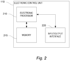
- Fig. 2 is a block diagram of the electronic control unit 110 of the lane change control system 105.
- the electronic control unit 110 includes a plurality of electrical and electronic components that provide power, operation control, and protection to the components and modules within the electronic control unit 110.
- the electronic control unit 110 includes, among other things, an electronic processor 210 (such as a programmable electronic microprocessor, microcontroller, or similar device), a memory 215 (for example, non-transitory, machine readable memory), and an input/output interface 220.
- the electronic processor 210 is communicatively connected to the memory 215 and the input/output interface 220.
- the electronic processor 210 in coordination with the memory 215 and the input/output interface 220, is configured to implement, among other things, the methods described herein.
- the electronic control unit 110 may be implemented in several independent controllers (for example, programmable electronic control units) each configured to perform specific functions or sub-functions. Additionally, the electronic control unit 110 may contain sub-modules that include additional electronic processors, memory, or application specific integrated circuits (ASICs) for handling input/output functions, processing of signals, and application of the methods listed below.
- the electronic control unit 110 includes additional, fewer, or different components
- Fig. 3 illustrates a method of operating the autonomous vehicle 100 with the lane change control system 105.
- the electronic processor 210 determines whether a lane change is about to occur (block 310). For example, the electronic processor 210 may receive a lane change request from another control system in the autonomous vehicle 100 or may initiate a lane change decision internally. When the lane change is about to occur, the electronic processor 210 detects a feature of a road surface with the sensor 115 (block 315). The electronic processor 210 creates an image of the road surface with the sensor 115.
- the electronic processor 210 may receive camera images from the sensor 115 and compare the camera images to determine disparities in the images.
- the electronic processor 210 may determine geometric properties of the road surface, or a portion thereof, including slope, shape, profile and orientation using the images.
- the electronic processor 210 may analyze one or more images from one or more stereo cameras, lidar sensors, or both to determine the geometric properties of the road surface.
- the electronic processor 210 detects traffic lane markers such as dashed lines or reflectors with the sensor 115 as illustrated in Figs. 4A-4C .
- the electronic processor 210 may receive images depicting the traffic lane markers in a target lane (the traffic lane targeted for the lane change). The images may be generated from forward facing, rear facing, side facing cameras, or lidar.
- the electronic processor 210 identifies a traffic lane marker dividing the current lane of travel with the target lane and a traffic lane marker indicative of the opposite side of the target lane.
- the electronic processor 210 may determine a distance in the received image between these two traffic lane markers, as illustrated on the left side of Figs. 4A-4C . In particular, the left side of Figs.
- FIG. 4A-4C depict the traffic lane markers within the image received at the electronic processor 210.
- this indicates a positive road camber as shown on the right side of Fig. 4A .
- the distance between the traffic lane markers appears nominal, as shown on the left side of Fig. 4B , this indicates a relatively flat surface as shown on the right side of Fig. 4B .
- the distance between the traffic lane markers appears large, as shown on the left side of Fig. 4C , this indicates a negative road camber as shown on the right side of Fig. 4C .
- the actual classification of small, nominal, or large may be performed based on the signal from the sensor 115 given an estimate of the actual adjacent lane width from sensor or map data.
- the electronic processor 210 determines a road camber based on the features (block 320).
- the features may include road geometry, traffic lane markers, or both as discussed above.
- the road camber may also be determined using various different techniques or a combination of different techniques.
- the road camber may be determined based on identification of the orientation of vehicles surrounding the autonomous vehicle 100, based on gravity vector determination through inertial sensing, based on road camber data provided in high definition road maps (for example, with data of road camber gathered from crowd sourcing), or a combination of the foregoing techniques.
- the electronic processor 210 may determine the road camber based on the distance between the traffic lane markers in the image and correlating this distance with known values of an actual distance between road markers. Once the road camber is determined, using one or more of the above-listed techniques, the electronic processor 210 determines a lateral compensating force based on the road camber (block 325). This may include predicting the lateral forces impinging on the autonomous vehicle 100 during the lane change maneuver. Performing a lane change maneuver over a road surface with a changing road camber results in changes in the lateral forces experienced by the occupants of the autonomous vehicle 100.
- the lateral compensating force counteracts the lateral force due to the road camber.
- the lateral compensating force may be set to a value that negates the lateral force by applying the compensating force in an equal and opposite direction to the lateral force due to road camber. This may create the effect of performing a lane change on a road surface with zero road camber or with no changes in road camber across traffic lanes.
- the compensating force may be variable and adjusted to continuously counteract the changes in lateral force that occur due to a changing road camber.
- Determining the lateral compensating force includes predicting the lateral force due to the road camber that will occur during the lane change.
- the lateral force due to the road camber may be partially dependent on various characteristics of the autonomous vehicle 100 such as weight, handling, speed, and others. As a consequence, the determination of the lateral compensating force may also be based on one or more of these predetermined characteristics of the autonomous vehicle 100.
- the lateral force due to the road camber also depends on the planned trajectory of the lane change.
- the electronic processor 210 determines the lateral compensating force based on the planned trajectory whether the planned trajectory is predetermined or calculated by the electronic processor 210 in response to a lane change request.
- the electronic processor 210 applies the lateral compensating force during the lane change maneuver (block 330). For example, the electronic processor 210 may adjust the steering control 120, the speed control 125, or both by applying a feed-forward control signal based on the lateral compensating force. The feed-forward control signal then counteracts the lateral force due to road camber throughout the lane change maneuver. The electronic processor 210 applies the lateral compensating force to assist a driver in performing a manual lane change maneuver. The electronic processor 210 assists the driver by automatically compensating for road camber and changes in the lateral forces on the autonomous vehicle 100 when the autonomous vehicle 100 is being operating manually.
- Fig. 5 illustrates a method of operating the autonomous vehicle 100 with the lane change control system 105. More particularly, Fig. 5 illustrates a method of determining or adjusting an already determined trajectory for a lane change maneuver based on the road camber.
- the electronic processor 210 determines the road camber of the target lane based on the features (block 505) according to the techniques described above.
- the electronic processor 210 determines a desired lateral acceleration during the lane change maneuver (block 510).
- the desired lateral acceleration is an approximate amount of lateral acceleration that occupants of the autonomous vehicle 100 feel comfortable experiencing.
- the electronic processor 210 plans a trajectory for the lane change maneuver based on the road camber and the desired lateral acceleration. Since the road camber affects the amount of lateral acceleration that the occupants of the autonomous vehicle 100 are exposed to, the electronic processor 210 plans the trajectory to compensate for the road camber change between lanes. For example, in road conditions with a high amount of change in road camber, occupants may experience higher levels of lateral acceleration than with road conditions with a low amount of change of road camber for a particular trajectory. To compensate for high levels of change in the road camber, the electronic processor 210 plans or determines a trajectory to accomplish a slower lane change maneuver to maintain a value of the lateral acceleration below the desired lateral acceleration.
- the electronic processor adjusts a planned trajectory based on the road camber and the desired lateral acceleration (block 520).
- the planned trajectory is at least in part predetermined or preprogrammed.
- the planned trajectory may also be generated by another electronic control unit within the autonomous vehicle 100.
- the electronic processor 210 adjusts the planned trajectory to maintain a value of the lateral acceleration below the desired lateral acceleration.
- the electronic processor 210 determines the lateral compensating force by setting the lateral compensating force to achieve the desired lateral acceleration of the autonomous vehicle 100.
- Applying the lateral compensating force includes planning a trajectory for the lane change maneuver that is based, at least in part, on achieving the desired lateral acceleration of the autonomous vehicle 100.
- applying the lateral compensating force includes also adjusting the planned trajectory for the lane change maneuver based on achieving the desired lateral acceleration of the autonomous vehicle 100.
- the electronic processor 210 performs lane change assist the above-listed methods Various features, advantages, and embodiments are set forth in the following claims.
Landscapes
- Engineering & Computer Science (AREA)
- Transportation (AREA)
- Mechanical Engineering (AREA)
- Automation & Control Theory (AREA)
- Physics & Mathematics (AREA)
- Chemical & Material Sciences (AREA)
- Combustion & Propulsion (AREA)
- General Physics & Mathematics (AREA)
- Multimedia (AREA)
- Theoretical Computer Science (AREA)
- Mathematical Physics (AREA)
- Control Of Driving Devices And Active Controlling Of Vehicle (AREA)
- Traffic Control Systems (AREA)
- Radar, Positioning & Navigation (AREA)
- Remote Sensing (AREA)
- Aviation & Aerospace Engineering (AREA)
- Artificial Intelligence (AREA)
- Evolutionary Computation (AREA)
- Game Theory and Decision Science (AREA)
- Medical Informatics (AREA)
- Health & Medical Sciences (AREA)
- Business, Economics & Management (AREA)
- Image Analysis (AREA)
Description
- Embodiments relate to a control systems for an autonomous vehicle.
- Modern vehicles include various autonomous driving functions, for example adaptive cruise-control, lane change assistance, collision avoidance systems, self-parking, and the like. Fully autonomous driving is a goal, but has not yet been achieved.
-
US 2014/343790 A1 describes a method of operating an autonomous vehicle, the method comprising: detecting a feature of a road surface with a sensor; determining, at an electronic processor, a road camber; determining a lateral compensating force based on the road camber applying the lateral compensating force, by the electronic processor, during the lane change maneuver. - The present invention provides a method according to claim 1 and a lane change control system of an autonomous vehicle according to claim 7.
- Embodiments provide a technique to reduce lateral position deviation during an automated lane change due to changes in road camber between the originating traffic lane and the target traffic lane. Road camber introduces a lateral force on a vehicle performing a lane change. To maintain a particular trajectory during the lane change, a compensating force may be applied by the vehicle steering or trajectory control system to maintain the trajectory during the lane change and to maintain a desired position within the target lane. The camber between lanes on a given road may differ substantially between adjacent lanes. As a consequence, different magnitudes and directions of compensating force may be required to maintain a trajectory. During an automated lane change, the vehicle trajectory control system may adapt to changes in compensating force to prevent unwanted deviations from the position within the target lane.
- Having knowledge of the target lane's camber relative to the originating lane allows for a feed-forward compensation of the lateral compensating force to minimize position deviations, and, if desired, modification of a desired vehicle trajectory. Feed-forward compensation may also be implemented to control lateral forces on vehicle occupants during the lane change maneuver. Once the target lane camber is determined, the lateral forces generated on the vehicle may be pre-determined with a vehicle model incorporating roll. The lateral forces due to the target lane camber may be compensated for by using an actuator controlling vehicle yaw or lateral motion (for example, steering actuator(s), differential braking, or torque vectoring). The lane change trajectory may also be modified in order to more accurately produce desired lateral forces on the vehicle occupants.
- Accounting for road camber in the feed-forward lateral control path reduces lateral position deviation during a lane change, thereby improving the comfort and safety of the automated lane change maneuver. Embodiments provide, among other things, a system and a method for determining a lateral compensating force and adjusting the vehicle's steering or trajectory control based on the lateral compensating force.
- Other aspects, features, and embodiments will become apparent by consideration of the detailed description and accompanying drawings.
-
-
Fig. 1 is a block diagram of an autonomous vehicle equipped with a lane change control system. -
Fig. 2 is a block diagram of an electronic control unit of the lane change control system ofFig. 1 . -
Fig. 3 is a flowchart of a method of operating the lane change control system ofFig. 1 . -
Figs. 4A-4C are diagrams of images of traffic lane markings and of detection of the traffic lane markings by the lane change control system ofFig. 1 . -
Fig. 5 is a flowchart of a method of operating the lane change control system ofFig. 1 . - Before any embodiments are explained in detail, it is to be understood that this disclosure is not intended to be limited in its application to the details of construction and the arrangement of components set forth in the following description or illustrated in the following drawings. Embodiments are capable of other configurations and of being practiced or of being carried out in various ways.
- A plurality of hardware and software based devices, as well as a plurality of different structural components may be used to implement various embodiments. In addition, embodiments may include hardware, software, and electronic components or modules that, for purposes of discussion, may be illustrated and described as if the majority of the components were implemented solely in hardware. However, one of ordinary skill in the art, and based on a reading of this detailed description, would recognize that, in at least one embodiment, the electronic based aspects of the invention may be implemented in software (for example, stored on non-transitory computer-readable medium) executable by one or more processors. For example, "control units" and "controllers" described in the specification can include one or more electronic processors, one or more memory modules including non-transitory computer-readable medium, one or more input/output interfaces, one or more application specific integrated circuits (ASICs), and various connections (for example, a system bus) connecting the various components.
-
Fig. 1 provides an illustrative example of anautonomous vehicle 100 equipped with a lanechange control system 105. Theautonomous vehicle 100, although illustrated as a four-wheeled vehicle, may encompass various types and designs of vehicles. For example, theautonomous vehicle 100 may be an automobile, a motorcycle, a truck, a bus, a semi-tractor, and others. Theautonomous vehicle 100 may not be fully autonomous but includes at least some autonomous functionality. Thus, theautonomous vehicle 100 may require a driver or operator to perform some driving functions. In the example illustrated, the lanechange control system 105 includes several hardware components including an electronic control unit (ECU) 110 and asensor 115. The lanechange control system 105 also includes asteering control 120 and aspeed control 125, which although illustrated as separate components from theelectronic control unit 110, may include hardware and software modules that are completely or at least partially incorporated within theelectronic control unit 110. In addition, thesteering control 120 may include active steering and yaw control. The components of the lanechange control system 105 may be of various constructions and may use various communication types and protocols. - The
electronic control unit 110 may be communicatively connected to thesensor 115, thesteering control 120, and thespeed control 125 via various wired or wireless connections. For example, theelectronic control unit 110 is directly coupled via a dedicated wire to each of the above-listed components of the lanechange control system 105. Theelectronic control unit 110 is communicatively coupled to one or more of the components via a shared communication link such as a vehicle communication bus (for example, a controller area network (CAN) bus) or a wireless vehicle network. - The
sensor 115 may be implemented using multiple sensors, sensor arrays, multiple sensing components, and multiple different types of sensors. Thesensor 115 may be positioned at various places on or within theautonomous vehicle 100. Thesensor 115 may have a field of view that extends, at least in part, to an area including an adjacent traffic lane. In one example, thesensor 115, or components thereof, is externally mounted to a portion of the autonomous vehicle 100 (for example, on a side mirror or front end). In another example, thesensor 115, or components thereof, is internally mounted within the autonomous vehicle 100 (for example, positioned on the dashboard or by the rearview mirror). Thesensor 115 includes a single video camera, multiple video cameras creating a stereo field of view, light detection and ranging (lidar) sensors, or some combination of the foregoing. Thesensor 115 is configured to sense a profile of at least a portion of the road surface, a position of lane markings, or both. - In another example of the components of the lane
change control system 105, thesteering control 120 may include a steering angle sensor, a steering actuator, and other components that directly or indirectly (for example, by differential braking, heading control, or yaw control) control the trajectory of the autonomous vehicle. Thespeed control 125 may include an electronically controlled device (for example, a throttle) and associated software for controlling power delivered to an engine of theautonomous vehicle 100. Thespeed control 125 also includes braking controls (for example, an electronic brake controller) and braking components that, in coordination, control the braking force of theautonomous vehicle 100, and thereby control the speed and direction of theautonomous vehicle 100. - Each of the above-listed components of the lane
change control system 105 may include dedicated processing circuitry including an electronic processor and memory for receiving, processing, and transmitting data associated with the functions of each component. For example, thesensor 115 may include an electronic processor that determines parameters relating to the ground surface and the lane markers. In this case, thesensor 115 transmits the parameters or calculated values associated with the parameters to theelectronic control unit 110. Each of the components of the lanechange control system 105 may communicate with theelectronic control unit 110 using various communication protocols. The autonomous vehicle illustrated inFig. 1 provides but one example of the components and connections of the lanechange control system 105. However, these components and connections may be constructed in other ways than those illustrated and described herein. -
Fig. 2 is a block diagram of theelectronic control unit 110 of the lanechange control system 105. Theelectronic control unit 110 includes a plurality of electrical and electronic components that provide power, operation control, and protection to the components and modules within theelectronic control unit 110. Theelectronic control unit 110 includes, among other things, an electronic processor 210 (such as a programmable electronic microprocessor, microcontroller, or similar device), a memory 215 (for example, non-transitory, machine readable memory), and an input/output interface 220. Theelectronic processor 210 is communicatively connected to thememory 215 and the input/output interface 220. Theelectronic processor 210, in coordination with thememory 215 and the input/output interface 220, is configured to implement, among other things, the methods described herein. - The
electronic control unit 110 may be implemented in several independent controllers (for example, programmable electronic control units) each configured to perform specific functions or sub-functions. Additionally, theelectronic control unit 110 may contain sub-modules that include additional electronic processors, memory, or application specific integrated circuits (ASICs) for handling input/output functions, processing of signals, and application of the methods listed below. Theelectronic control unit 110 includes additional, fewer, or different components -
Fig. 3 illustrates a method of operating theautonomous vehicle 100 with the lanechange control system 105. In the illustrated method, theelectronic processor 210 determines whether a lane change is about to occur (block 310). For example, theelectronic processor 210 may receive a lane change request from another control system in theautonomous vehicle 100 or may initiate a lane change decision internally. When the lane change is about to occur, theelectronic processor 210 detects a feature of a road surface with the sensor 115 (block 315). Theelectronic processor 210 creates an image of the road surface with thesensor 115. - The
electronic processor 210 may receive camera images from thesensor 115 and compare the camera images to determine disparities in the images. Theelectronic processor 210 may determine geometric properties of the road surface, or a portion thereof, including slope, shape, profile and orientation using the images. Theelectronic processor 210 may analyze one or more images from one or more stereo cameras, lidar sensors, or both to determine the geometric properties of the road surface. - The
electronic processor 210 detects traffic lane markers such as dashed lines or reflectors with thesensor 115 as illustrated inFigs. 4A-4C . In this case, theelectronic processor 210 may receive images depicting the traffic lane markers in a target lane (the traffic lane targeted for the lane change). The images may be generated from forward facing, rear facing, side facing cameras, or lidar. Theelectronic processor 210 identifies a traffic lane marker dividing the current lane of travel with the target lane and a traffic lane marker indicative of the opposite side of the target lane. Theelectronic processor 210 may determine a distance in the received image between these two traffic lane markers, as illustrated on the left side ofFigs. 4A-4C . In particular, the left side ofFigs. 4A-4C depict the traffic lane markers within the image received at theelectronic processor 210. When the distance between the traffic lane markers appears small, as shown on the left side ofFig. 4A , this indicates a positive road camber as shown on the right side ofFig. 4A . When the distance between the traffic lane markers appears nominal, as shown on the left side ofFig. 4B , this indicates a relatively flat surface as shown on the right side ofFig. 4B . When the distance between the traffic lane markers appears large, as shown on the left side ofFig. 4C , this indicates a negative road camber as shown on the right side ofFig. 4C . The actual classification of small, nominal, or large may be performed based on the signal from thesensor 115 given an estimate of the actual adjacent lane width from sensor or map data. - Returning to the discussion of the method illustrated in
Fig. 3 , theelectronic processor 210 then determines a road camber based on the features (block 320). The features may include road geometry, traffic lane markers, or both as discussed above. The road camber may also be determined using various different techniques or a combination of different techniques. For example, the road camber may be determined based on identification of the orientation of vehicles surrounding theautonomous vehicle 100, based on gravity vector determination through inertial sensing, based on road camber data provided in high definition road maps (for example, with data of road camber gathered from crowd sourcing), or a combination of the foregoing techniques. - In one example, when detecting traffic lane markers, the
electronic processor 210 may determine the road camber based on the distance between the traffic lane markers in the image and correlating this distance with known values of an actual distance between road markers. Once the road camber is determined, using one or more of the above-listed techniques, theelectronic processor 210 determines a lateral compensating force based on the road camber (block 325). This may include predicting the lateral forces impinging on theautonomous vehicle 100 during the lane change maneuver. Performing a lane change maneuver over a road surface with a changing road camber results in changes in the lateral forces experienced by the occupants of theautonomous vehicle 100. For example, when theautonomous vehicle 100 changes lanes, the road camber between these lanes may change, resulting in a change in the lateral forces on theautonomous vehicle 100. The lateral compensating force counteracts the lateral force due to the road camber. The lateral compensating force may be set to a value that negates the lateral force by applying the compensating force in an equal and opposite direction to the lateral force due to road camber. This may create the effect of performing a lane change on a road surface with zero road camber or with no changes in road camber across traffic lanes. The compensating force may be variable and adjusted to continuously counteract the changes in lateral force that occur due to a changing road camber. - Determining the lateral compensating force includes predicting the lateral force due to the road camber that will occur during the lane change. The lateral force due to the road camber may be partially dependent on various characteristics of the
autonomous vehicle 100 such as weight, handling, speed, and others. As a consequence, the determination of the lateral compensating force may also be based on one or more of these predetermined characteristics of theautonomous vehicle 100. The lateral force due to the road camber also depends on the planned trajectory of the lane change. Theelectronic processor 210 determines the lateral compensating force based on the planned trajectory whether the planned trajectory is predetermined or calculated by theelectronic processor 210 in response to a lane change request. - Once the lateral compensating force is determined, the
electronic processor 210 applies the lateral compensating force during the lane change maneuver (block 330). For example, theelectronic processor 210 may adjust thesteering control 120, thespeed control 125, or both by applying a feed-forward control signal based on the lateral compensating force. The feed-forward control signal then counteracts the lateral force due to road camber throughout the lane change maneuver. Theelectronic processor 210 applies the lateral compensating force to assist a driver in performing a manual lane change maneuver. Theelectronic processor 210 assists the driver by automatically compensating for road camber and changes in the lateral forces on theautonomous vehicle 100 when theautonomous vehicle 100 is being operating manually. -
Fig. 5 illustrates a method of operating theautonomous vehicle 100 with the lanechange control system 105. More particularly,Fig. 5 illustrates a method of determining or adjusting an already determined trajectory for a lane change maneuver based on the road camber. In the illustrated method, theelectronic processor 210 determines the road camber of the target lane based on the features (block 505) according to the techniques described above. Theelectronic processor 210 determines a desired lateral acceleration during the lane change maneuver (block 510). The desired lateral acceleration is an approximate amount of lateral acceleration that occupants of theautonomous vehicle 100 feel comfortable experiencing. - The
electronic processor 210 then plans a trajectory for the lane change maneuver based on the road camber and the desired lateral acceleration. Since the road camber affects the amount of lateral acceleration that the occupants of theautonomous vehicle 100 are exposed to, theelectronic processor 210 plans the trajectory to compensate for the road camber change between lanes. For example, in road conditions with a high amount of change in road camber, occupants may experience higher levels of lateral acceleration than with road conditions with a low amount of change of road camber for a particular trajectory. To compensate for high levels of change in the road camber, theelectronic processor 210 plans or determines a trajectory to accomplish a slower lane change maneuver to maintain a value of the lateral acceleration below the desired lateral acceleration. - the electronic processor adjusts a planned trajectory based on the road camber and the desired lateral acceleration (block 520). In this case, the planned trajectory is at least in part predetermined or preprogrammed. The planned trajectory may also be generated by another electronic control unit within the
autonomous vehicle 100. In these cases, theelectronic processor 210 adjusts the planned trajectory to maintain a value of the lateral acceleration below the desired lateral acceleration. - The
electronic processor 210 determines the lateral compensating force by setting the lateral compensating force to achieve the desired lateral acceleration of theautonomous vehicle 100. Applying the lateral compensating force (as illustrated in block 330) includes planning a trajectory for the lane change maneuver that is based, at least in part, on achieving the desired lateral acceleration of theautonomous vehicle 100. Similarly, applying the lateral compensating force includes also adjusting the planned trajectory for the lane change maneuver based on achieving the desired lateral acceleration of theautonomous vehicle 100. - The
electronic processor 210 performs lane change assist the above-listed methods Various features, advantages, and embodiments are set forth in the following claims.
Claims (12)
- A method of operating an autonomous vehicle (100), the method comprising:determining whether a lane change is about to occur;detecting a feature of a road surface with a sensor (115);determining, at an electronic processor (210), a road camber of a target lane based on the feature, the target lane being a traffic lane targeted for a lane change maneuver by the autonomous vehicle (100);predicting a lateral force due to the road camber on the autonomous vehicle (100), the lateral force occurring during the lane change maneuver;setting a lateral compensating force equal and opposite to the lateral force due to the road camber to achieve a desired lateral acceleration of the autonomous vehicle (100);applying the lateral compensating force, by the electronic processor (210), during the lane change maneuver, wherein applying the lateral compensating force includes planning a trajectory for the lane change maneuver that is based, at least in part, on achieving the desired lateral acceleration of the autonomous vehicle (100).
- The method according to Claim 1, wherein predicting the lateral force due to the road camber is based on predetermined characteristics of the autonomous vehicle (100).
- The method according to Claim 1, wherein predicting the lateral force due to the road camber is based on a planned trajectory of the lane change maneuver.
- The method according to Claim 1, wherein detecting the feature of the road surface includes detecting a profile of a portion of the road surface using stereo cameras, and wherein determining the road camber of the target lane includes determining the road camber based on the profile of the portion of the road surface.
- The method according to Claim 1, wherein detecting the feature of the road surface includes detecting a profile of a portion of the road surface using a lidar sensor (115), and wherein determining the road camber of the target lane includes determining the road camber based on the profile of the portion of the road surface.
- The method according to Claim 1, wherein detecting the feature of the road surface includes detecting lane markers within an image generated by the sensor (115), wherein determining the road camber of the target lane includes determining a distance between detected lane markers within the image and determining the road camber based on the distance between detected lane markers within the image and a known value of an actual distance between road markers.
- A lane change control system (105) of an autonomous vehicle (100) comprising:a sensor (115); andan electronic processor (210) communicatively connected to the sensor (115), the electronic processor (210) configured todetermine whether a lane change is about to occur;detect a feature of a road surface with the sensor (115),determine a road camber of a target lane based on the feature, the target lane being a traffic lane targeted for a lane change maneuver by the autonomous vehicle (100),predict a lateral force due to the road camber on the autonomous vehicle (100), the lateral force occurring during the lane change maneuver;set a lateral compensating force equal and opposite to the lateral force due to the road camber to achieve a desired lateral acceleration of the autonomous vehicle (100);and apply the lateral compensating force, by the electronic processor (210), during the lane change maneuver, wherein applying the lateral compensating force includes planning a trajectory for the lane change maneuver that is based, at least in part, on achieving the desired lateral acceleration of the autonomous vehicle (100).
- The lane change control system (105) according to Claim 7, wherein the electronic processor (210) is further configured to predict the lateral force due to the road camber based on predetermined characteristics of the autonomous vehicle (100).
- The lane change control system (105) according to Claim 7, wherein the electronic processor (210) is further configured to predict the lateral force due to the road camber based on a planned trajectory of the lane change maneuver.
- The lane change control system (105) according to Claim 7, wherein the electronic processor (210) is further configured to detect a profile of a portion of the road surface using stereo cameras and to determine the road camber based on the profile of the portion of the road surface.
- The lane change control system (105) according to Claim 7, wherein the electronic processor (210) is further configured to detect a profile of a portion of the road surface using a lidar sensor (115) and to determine the road camber based on the profile of the portion of the road surface.
- The lane change control system (105) according to Claim 7, wherein the electronic processor (210) is further configured to detect lane markers within an image generated by the sensor (115), determine a distance between detected lane markers within the image, and to determine the road camber based on the distance between detected lane markers within the image and a known value of an actual distance between road markers.
Applications Claiming Priority (2)
| Application Number | Priority Date | Filing Date | Title |
|---|---|---|---|
| US15/398,222 US10150474B2 (en) | 2017-01-04 | 2017-01-04 | Reducing lateral position deviation during an automated lane change |
| PCT/EP2017/084155 WO2018127430A1 (en) | 2017-01-04 | 2017-12-21 | Reducing lateral position deviation during an automated lane change |
Publications (2)
| Publication Number | Publication Date |
|---|---|
| EP3566220A1 EP3566220A1 (en) | 2019-11-13 |
| EP3566220B1 true EP3566220B1 (en) | 2021-12-01 |
Family
ID=60943005
Family Applications (1)
| Application Number | Title | Priority Date | Filing Date |
|---|---|---|---|
| EP17826235.8A Active EP3566220B1 (en) | 2017-01-04 | 2017-12-21 | Reducing lateral position deviation during an automated lane change |
Country Status (5)
| Country | Link |
|---|---|
| US (1) | US10150474B2 (en) |
| EP (1) | EP3566220B1 (en) |
| JP (1) | JP6926210B2 (en) |
| CN (1) | CN110114254B (en) |
| WO (1) | WO2018127430A1 (en) |
Families Citing this family (18)
| Publication number | Priority date | Publication date | Assignee | Title |
|---|---|---|---|---|
| US12403932B2 (en) * | 2016-06-21 | 2025-09-02 | Robert C. Brasher | Autonomous vehicle navigation of bypass merge lanes |
| US10290214B2 (en) * | 2017-04-11 | 2019-05-14 | Denso International America, Inc. | Lane change system and lane change controller |
| JP6773215B2 (en) * | 2017-04-14 | 2020-10-21 | 日産自動車株式会社 | Vehicle control method and vehicle control device |
| CN110018632B (en) * | 2018-06-22 | 2020-10-09 | 长城汽车股份有限公司 | Vehicle lane change control method and device |
| EP3650297B1 (en) * | 2018-11-08 | 2023-06-14 | Bayerische Motoren Werke Aktiengesellschaft | Method and apparatus for determining information related to a lane change of a target vehicle, and computer program |
| KR102716359B1 (en) * | 2018-12-14 | 2024-10-10 | 현대자동차주식회사 | Apparatus and method for controlling driving of vehicle |
| CN110796858A (en) * | 2019-10-24 | 2020-02-14 | 山东科技大学 | A vehicle trajectory prediction method and system based on video passing data |
| US11407419B2 (en) * | 2019-12-30 | 2022-08-09 | Baidu Usa Llc | Central line shifting based pre-change lane path planning |
| CN114074706B (en) * | 2020-08-19 | 2023-06-30 | 蜂巢智能转向系统(江苏)有限公司 | Electric power steering system, off-tracking compensation arbitration method and equipment |
| US12030518B2 (en) | 2021-04-06 | 2024-07-09 | Atieva, Inc. | Lane changing based only on local information |
| JP7521701B2 (en) * | 2021-06-11 | 2024-07-24 | 日産自動車株式会社 | Vehicle control method and vehicle control device |
| CN114275039B (en) * | 2021-12-27 | 2022-11-04 | 联创汽车电子有限公司 | Intelligent driving vehicle transverse control method and module |
| DE102022101492A1 (en) * | 2022-01-24 | 2023-07-27 | Bayerische Motoren Werke Aktiengesellschaft | Method and device for determining pose data relating to the pose of a vehicle |
| DE102022109423A1 (en) * | 2022-04-19 | 2023-10-19 | Valeo Schalter Und Sensoren Gmbh | Method for the lateral localization of a vehicle on a road, computer program and driver assistance system |
| US12522240B2 (en) | 2023-07-20 | 2026-01-13 | Atieva, Inc. | Controlling vehicle using static objects and vehicle curvature |
| US12515696B2 (en) | 2023-07-20 | 2026-01-06 | Atieva, Inc. | Controlling vehicle using static objects and heading angle |
| US12428059B2 (en) | 2023-08-14 | 2025-09-30 | Atieva, Inc. | Manual lane biasing mode for ADAS |
| GB2642475A (en) * | 2024-07-09 | 2026-01-14 | Mercedes Benz Group Ag | Vehicle sway warning system for detecting unintentional sways of a vehicle and method |
Family Cites Families (43)
| Publication number | Priority date | Publication date | Assignee | Title |
|---|---|---|---|---|
| JP3024413B2 (en) * | 1993-01-27 | 2000-03-21 | トヨタ自動車株式会社 | Rear wheel control device for four-wheel steering vehicles |
| GB9317983D0 (en) | 1993-08-28 | 1993-10-13 | Lucas Ind Plc | A driver assistance system for a vehicle |
| DE4332836C1 (en) * | 1993-09-27 | 1994-09-15 | Daimler Benz Ag | Device for steering a vehicle with controlled tracking |
| DE19517401C1 (en) * | 1995-05-15 | 1996-09-26 | Hydac Technology Gmbh | Equalisation device for rail locomotive transformer |
| US5899952A (en) * | 1995-12-27 | 1999-05-04 | Toyota Jidosha Kabushiki Kaisha | Device for estimating slip angle of vehicle body through interrelation thereof with yaw rate |
| EP1147960A1 (en) * | 2000-04-18 | 2001-10-24 | Société de Technologie Michelin | Vehicle stability control method using tyre lateral forces |
| JP3530803B2 (en) * | 2000-05-22 | 2004-05-24 | 三菱電機株式会社 | Vehicle detection device |
| ITTO20020129A1 (en) | 2002-02-15 | 2003-08-18 | Fiat Ricerche | VEHICLE DRIVING AID SYSTEM. |
| JP3870911B2 (en) * | 2003-02-10 | 2007-01-24 | 日産自動車株式会社 | Lane departure prevention device |
| US7421334B2 (en) | 2003-04-07 | 2008-09-02 | Zoom Information Systems | Centralized facility and intelligent on-board vehicle platform for collecting, analyzing and distributing information relating to transportation infrastructure and conditions |
| ITMI20050788A1 (en) | 2005-05-02 | 2006-11-03 | Iveco Spa | RIDING AID SYSTEM TO SUPPORT THE CORSA MAINTENANCE TO ASSIST THE CHANGE OF SLIDES AND MONITOR THE STATE OF THE DRIVER OF A VEHICLE |
| US8983765B2 (en) * | 2006-10-11 | 2015-03-17 | GM Global Technology Operations LLC | Method and system for lane centering control |
| JP2008207805A (en) * | 2008-03-28 | 2008-09-11 | Toyota Motor Corp | Vehicle departure prevention device |
| US8392064B2 (en) | 2008-05-27 | 2013-03-05 | The Board Of Trustees Of The Leland Stanford Junior University | Systems, methods and devices for adaptive steering control of automotive vehicles |
| US20100228427A1 (en) * | 2009-03-05 | 2010-09-09 | Massachusetts Institute Of Technology | Predictive semi-autonomous vehicle navigation system |
| WO2011140993A1 (en) | 2010-05-12 | 2011-11-17 | 北京星河易达科技有限公司 | Intelligent traffic safety system based on comprehensive state detection and decision method thereof |
| JP2012086793A (en) * | 2010-10-22 | 2012-05-10 | Jtekt Corp | Electric power steering device |
| DE102010055136A1 (en) * | 2010-12-18 | 2012-07-05 | Audi Ag | Method for operating a transverse driver assistance system of a motor vehicle and motor vehicle |
| JP5760720B2 (en) * | 2011-06-08 | 2015-08-12 | いすゞ自動車株式会社 | Road gradient estimation device |
| KR101294059B1 (en) * | 2011-07-28 | 2013-08-08 | 현대자동차주식회사 | Lane keep assistance system using in-wheel system |
| US8903607B2 (en) * | 2012-01-11 | 2014-12-02 | GM Global Technology Operations LLC | Lane tracking system with active rear-steer |
| US9463574B2 (en) * | 2012-03-01 | 2016-10-11 | Irobot Corporation | Mobile inspection robot |
| JP5333624B2 (en) * | 2012-04-09 | 2013-11-06 | アイシン・エィ・ダブリュ株式会社 | Vehicle control apparatus and vehicle control method |
| JP5997962B2 (en) * | 2012-07-27 | 2016-09-28 | クラリオン株式会社 | In-vehicle lane marker recognition device |
| DE102014204461B4 (en) | 2013-05-14 | 2018-10-31 | Ford Global Technologies, Llc | Method for improving the straight-line stability of a vehicle |
| DE102013009252A1 (en) * | 2013-06-03 | 2014-12-04 | Trw Automotive Gmbh | Control unit and method for an emergency steering assist function |
| US9604670B2 (en) * | 2013-06-28 | 2017-03-28 | Nissan Motor Co., Ltd. | Steering control device |
| JP6201561B2 (en) * | 2013-09-20 | 2017-09-27 | 株式会社デンソー | Traveling track generation device and traveling track generation program |
| US9278713B2 (en) * | 2013-12-11 | 2016-03-08 | GM Global Technology Operations LLC | Collision avoidance control integrated with EPS controller |
| US9988047B2 (en) * | 2013-12-12 | 2018-06-05 | Magna Electronics Inc. | Vehicle control system with traffic driving control |
| JP5798658B1 (en) | 2014-03-28 | 2015-10-21 | 富士重工業株式会社 | Vehicle lane departure prevention control device |
| JP6252399B2 (en) * | 2014-08-12 | 2017-12-27 | トヨタ自動車株式会社 | Lane change support device |
| US9229453B1 (en) * | 2014-08-29 | 2016-01-05 | GM Global Technology Operations LLC | Unified motion planner for autonomous driving vehicle in avoiding the moving obstacle |
| US20160096546A1 (en) * | 2014-10-03 | 2016-04-07 | Delphi Technologies, Inc. | Lane departure steering correction with road camber and crosswind compensation |
| JP6470039B2 (en) * | 2014-12-26 | 2019-02-13 | 日立オートモティブシステムズ株式会社 | Vehicle control system |
| DE102015209467A1 (en) * | 2015-05-22 | 2016-11-24 | Continental Teves Ag & Co. Ohg | Method of estimating lanes |
| US9513632B1 (en) * | 2015-09-16 | 2016-12-06 | International Business Machines Corporation | Driving mode alerts from self-driving vehicles |
| WO2017047261A1 (en) * | 2015-09-17 | 2017-03-23 | 日立オートモティブシステムズ株式会社 | Lane change control device |
| US9731755B1 (en) * | 2016-02-16 | 2017-08-15 | GM Global Technology Operations LLC | Preview lateral control for automated driving |
| US9789880B2 (en) * | 2016-03-03 | 2017-10-17 | Uber Technologies, Inc. | Sensory stimulation system for an autonomous vehicle |
| US10248871B2 (en) * | 2016-03-24 | 2019-04-02 | Qualcomm Incorporated | Autonomous lane detection |
| US10479357B2 (en) * | 2016-05-23 | 2019-11-19 | Aptiv Technologies Limited | Lane keeping system for autonomous vehicle in wind conditions |
| US10137890B2 (en) * | 2016-06-28 | 2018-11-27 | Toyota Motor Engineering & Manufacturing North America, Inc. | Occluded obstacle classification for vehicles |
-
2017
- 2017-01-04 US US15/398,222 patent/US10150474B2/en active Active
- 2017-12-21 JP JP2019536283A patent/JP6926210B2/en active Active
- 2017-12-21 WO PCT/EP2017/084155 patent/WO2018127430A1/en not_active Ceased
- 2017-12-21 EP EP17826235.8A patent/EP3566220B1/en active Active
- 2017-12-21 CN CN201780082173.4A patent/CN110114254B/en active Active
Also Published As
| Publication number | Publication date |
|---|---|
| JP6926210B2 (en) | 2021-08-25 |
| JP2020506837A (en) | 2020-03-05 |
| CN110114254B (en) | 2022-04-29 |
| CN110114254A (en) | 2019-08-09 |
| WO2018127430A1 (en) | 2018-07-12 |
| US10150474B2 (en) | 2018-12-11 |
| EP3566220A1 (en) | 2019-11-13 |
| US20180186371A1 (en) | 2018-07-05 |
Similar Documents
| Publication | Publication Date | Title |
|---|---|---|
| EP3566220B1 (en) | Reducing lateral position deviation during an automated lane change | |
| EP3052961B1 (en) | Adaptive cruise control with on-ramp detection | |
| EP2143611B1 (en) | Vehicle behavior controller | |
| US10755573B2 (en) | Collision avoidance device | |
| US9238463B2 (en) | Driving assistance system for vehicle and system for estimating frictional state of road surface | |
| US12168436B2 (en) | Vehicle motion control apparatus, vehicle motion control method, and vehicle motion control system | |
| JP6222786B2 (en) | Vehicle travel control device | |
| US11338801B2 (en) | Collision avoidance device | |
| CN108032858B (en) | Adaptive cruise control method and system based on bypass driving path prediction | |
| CN107031630A (en) | The travel controlling system of vehicle | |
| US11738749B2 (en) | Methods, systems, and apparatuses for scenario-based path and intervention adaptation for lane-keeping assist systems | |
| KR102355735B1 (en) | System and Method for Lane Keep Asistance | |
| US9783198B2 (en) | Vehicle travel control device | |
| JP2017117192A (en) | Driving assistance device | |
| WO2021140236A1 (en) | Vehicle control system and method | |
| KR20200081524A (en) | Vehicle, and control method for the same | |
| CN110099832B (en) | Adaptive speed control system for autonomous vehicles | |
| US10392051B2 (en) | Vehicle driving assist apparatus | |
| JP7647639B2 (en) | Vehicle control device | |
| US20230294690A1 (en) | Method for automated management of the longitudinal speed of a vehicle | |
| CN114906127A (en) | Attitude control device | |
| GB2615203A (en) | Vehicle control system and method | |
| JP2008195162A (en) | Vehicle field of view securing device |
Legal Events
| Date | Code | Title | Description |
|---|---|---|---|
| STAA | Information on the status of an ep patent application or granted ep patent |
Free format text: STATUS: UNKNOWN |
|
| STAA | Information on the status of an ep patent application or granted ep patent |
Free format text: STATUS: THE INTERNATIONAL PUBLICATION HAS BEEN MADE |
|
| PUAI | Public reference made under article 153(3) epc to a published international application that has entered the european phase |
Free format text: ORIGINAL CODE: 0009012 |
|
| STAA | Information on the status of an ep patent application or granted ep patent |
Free format text: STATUS: REQUEST FOR EXAMINATION WAS MADE |
|
| 17P | Request for examination filed |
Effective date: 20190805 |
|
| AK | Designated contracting states |
Kind code of ref document: A1 Designated state(s): AL AT BE BG CH CY CZ DE DK EE ES FI FR GB GR HR HU IE IS IT LI LT LU LV MC MK MT NL NO PL PT RO RS SE SI SK SM TR |
|
| AX | Request for extension of the european patent |
Extension state: BA ME |
|
| DAV | Request for validation of the european patent (deleted) | ||
| DAX | Request for extension of the european patent (deleted) | ||
| RAP1 | Party data changed (applicant data changed or rights of an application transferred) |
Owner name: ROBERT BOSCH GMBH |
|
| STAA | Information on the status of an ep patent application or granted ep patent |
Free format text: STATUS: EXAMINATION IS IN PROGRESS |
|
| 17Q | First examination report despatched |
Effective date: 20210414 |
|
| GRAP | Despatch of communication of intention to grant a patent |
Free format text: ORIGINAL CODE: EPIDOSNIGR1 |
|
| STAA | Information on the status of an ep patent application or granted ep patent |
Free format text: STATUS: GRANT OF PATENT IS INTENDED |
|
| RIC1 | Information provided on ipc code assigned before grant |
Ipc: G08G 1/16 20060101AFI20210621BHEP Ipc: G06K 9/00 20060101ALI20210621BHEP Ipc: B62D 6/08 20060101ALI20210621BHEP Ipc: B62D 15/02 20060101ALI20210621BHEP Ipc: B60W 30/02 20120101ALI20210621BHEP Ipc: B60W 30/18 20120101ALI20210621BHEP Ipc: B60W 40/06 20120101ALI20210621BHEP Ipc: B60W 40/109 20120101ALI20210621BHEP |
|
| INTG | Intention to grant announced |
Effective date: 20210715 |
|
| GRAS | Grant fee paid |
Free format text: ORIGINAL CODE: EPIDOSNIGR3 |
|
| GRAA | (expected) grant |
Free format text: ORIGINAL CODE: 0009210 |
|
| STAA | Information on the status of an ep patent application or granted ep patent |
Free format text: STATUS: THE PATENT HAS BEEN GRANTED |
|
| AK | Designated contracting states |
Kind code of ref document: B1 Designated state(s): AL AT BE BG CH CY CZ DE DK EE ES FI FR GB GR HR HU IE IS IT LI LT LU LV MC MK MT NL NO PL PT RO RS SE SI SK SM TR |
|
| REG | Reference to a national code |
Ref country code: GB Ref legal event code: FG4D |
|
| REG | Reference to a national code |
Ref country code: AT Ref legal event code: REF Ref document number: 1452544 Country of ref document: AT Kind code of ref document: T Effective date: 20211215 Ref country code: CH Ref legal event code: EP |
|
| REG | Reference to a national code |
Ref country code: IE Ref legal event code: FG4D |
|
| REG | Reference to a national code |
Ref country code: DE Ref legal event code: R096 Ref document number: 602017050343 Country of ref document: DE |
|
| REG | Reference to a national code |
Ref country code: LT Ref legal event code: MG9D |
|
| REG | Reference to a national code |
Ref country code: NL Ref legal event code: MP Effective date: 20211201 |
|
| REG | Reference to a national code |
Ref country code: AT Ref legal event code: MK05 Ref document number: 1452544 Country of ref document: AT Kind code of ref document: T Effective date: 20211201 |
|
| PG25 | Lapsed in a contracting state [announced via postgrant information from national office to epo] |
Ref country code: RS Free format text: LAPSE BECAUSE OF FAILURE TO SUBMIT A TRANSLATION OF THE DESCRIPTION OR TO PAY THE FEE WITHIN THE PRESCRIBED TIME-LIMIT Effective date: 20211201 Ref country code: LT Free format text: LAPSE BECAUSE OF FAILURE TO SUBMIT A TRANSLATION OF THE DESCRIPTION OR TO PAY THE FEE WITHIN THE PRESCRIBED TIME-LIMIT Effective date: 20211201 Ref country code: FI Free format text: LAPSE BECAUSE OF FAILURE TO SUBMIT A TRANSLATION OF THE DESCRIPTION OR TO PAY THE FEE WITHIN THE PRESCRIBED TIME-LIMIT Effective date: 20211201 Ref country code: BG Free format text: LAPSE BECAUSE OF FAILURE TO SUBMIT A TRANSLATION OF THE DESCRIPTION OR TO PAY THE FEE WITHIN THE PRESCRIBED TIME-LIMIT Effective date: 20220301 Ref country code: AT Free format text: LAPSE BECAUSE OF FAILURE TO SUBMIT A TRANSLATION OF THE DESCRIPTION OR TO PAY THE FEE WITHIN THE PRESCRIBED TIME-LIMIT Effective date: 20211201 |
|
| PG25 | Lapsed in a contracting state [announced via postgrant information from national office to epo] |
Ref country code: SE Free format text: LAPSE BECAUSE OF FAILURE TO SUBMIT A TRANSLATION OF THE DESCRIPTION OR TO PAY THE FEE WITHIN THE PRESCRIBED TIME-LIMIT Effective date: 20211201 Ref country code: PL Free format text: LAPSE BECAUSE OF FAILURE TO SUBMIT A TRANSLATION OF THE DESCRIPTION OR TO PAY THE FEE WITHIN THE PRESCRIBED TIME-LIMIT Effective date: 20211201 Ref country code: NO Free format text: LAPSE BECAUSE OF FAILURE TO SUBMIT A TRANSLATION OF THE DESCRIPTION OR TO PAY THE FEE WITHIN THE PRESCRIBED TIME-LIMIT Effective date: 20220301 Ref country code: LV Free format text: LAPSE BECAUSE OF FAILURE TO SUBMIT A TRANSLATION OF THE DESCRIPTION OR TO PAY THE FEE WITHIN THE PRESCRIBED TIME-LIMIT Effective date: 20211201 Ref country code: HR Free format text: LAPSE BECAUSE OF FAILURE TO SUBMIT A TRANSLATION OF THE DESCRIPTION OR TO PAY THE FEE WITHIN THE PRESCRIBED TIME-LIMIT Effective date: 20211201 Ref country code: GR Free format text: LAPSE BECAUSE OF FAILURE TO SUBMIT A TRANSLATION OF THE DESCRIPTION OR TO PAY THE FEE WITHIN THE PRESCRIBED TIME-LIMIT Effective date: 20220302 Ref country code: ES Free format text: LAPSE BECAUSE OF FAILURE TO SUBMIT A TRANSLATION OF THE DESCRIPTION OR TO PAY THE FEE WITHIN THE PRESCRIBED TIME-LIMIT Effective date: 20211201 |
|
| PG25 | Lapsed in a contracting state [announced via postgrant information from national office to epo] |
Ref country code: NL Free format text: LAPSE BECAUSE OF FAILURE TO SUBMIT A TRANSLATION OF THE DESCRIPTION OR TO PAY THE FEE WITHIN THE PRESCRIBED TIME-LIMIT Effective date: 20211201 |
|
| PG25 | Lapsed in a contracting state [announced via postgrant information from national office to epo] |
Ref country code: SM Free format text: LAPSE BECAUSE OF FAILURE TO SUBMIT A TRANSLATION OF THE DESCRIPTION OR TO PAY THE FEE WITHIN THE PRESCRIBED TIME-LIMIT Effective date: 20211201 Ref country code: SK Free format text: LAPSE BECAUSE OF FAILURE TO SUBMIT A TRANSLATION OF THE DESCRIPTION OR TO PAY THE FEE WITHIN THE PRESCRIBED TIME-LIMIT Effective date: 20211201 Ref country code: RO Free format text: LAPSE BECAUSE OF FAILURE TO SUBMIT A TRANSLATION OF THE DESCRIPTION OR TO PAY THE FEE WITHIN THE PRESCRIBED TIME-LIMIT Effective date: 20211201 Ref country code: PT Free format text: LAPSE BECAUSE OF FAILURE TO SUBMIT A TRANSLATION OF THE DESCRIPTION OR TO PAY THE FEE WITHIN THE PRESCRIBED TIME-LIMIT Effective date: 20220401 Ref country code: EE Free format text: LAPSE BECAUSE OF FAILURE TO SUBMIT A TRANSLATION OF THE DESCRIPTION OR TO PAY THE FEE WITHIN THE PRESCRIBED TIME-LIMIT Effective date: 20211201 Ref country code: CZ Free format text: LAPSE BECAUSE OF FAILURE TO SUBMIT A TRANSLATION OF THE DESCRIPTION OR TO PAY THE FEE WITHIN THE PRESCRIBED TIME-LIMIT Effective date: 20211201 |
|
| REG | Reference to a national code |
Ref country code: CH Ref legal event code: PL |
|
| PG25 | Lapsed in a contracting state [announced via postgrant information from national office to epo] |
Ref country code: MC Free format text: LAPSE BECAUSE OF FAILURE TO SUBMIT A TRANSLATION OF THE DESCRIPTION OR TO PAY THE FEE WITHIN THE PRESCRIBED TIME-LIMIT Effective date: 20211201 |
|
| REG | Reference to a national code |
Ref country code: DE Ref legal event code: R097 Ref document number: 602017050343 Country of ref document: DE |
|
| REG | Reference to a national code |
Ref country code: BE Ref legal event code: MM Effective date: 20211231 |
|
| PG25 | Lapsed in a contracting state [announced via postgrant information from national office to epo] |
Ref country code: IS Free format text: LAPSE BECAUSE OF FAILURE TO SUBMIT A TRANSLATION OF THE DESCRIPTION OR TO PAY THE FEE WITHIN THE PRESCRIBED TIME-LIMIT Effective date: 20220401 |
|
| PLBE | No opposition filed within time limit |
Free format text: ORIGINAL CODE: 0009261 |
|
| STAA | Information on the status of an ep patent application or granted ep patent |
Free format text: STATUS: NO OPPOSITION FILED WITHIN TIME LIMIT |
|
| PG25 | Lapsed in a contracting state [announced via postgrant information from national office to epo] |
Ref country code: LU Free format text: LAPSE BECAUSE OF NON-PAYMENT OF DUE FEES Effective date: 20211221 Ref country code: IE Free format text: LAPSE BECAUSE OF NON-PAYMENT OF DUE FEES Effective date: 20211221 Ref country code: DK Free format text: LAPSE BECAUSE OF FAILURE TO SUBMIT A TRANSLATION OF THE DESCRIPTION OR TO PAY THE FEE WITHIN THE PRESCRIBED TIME-LIMIT Effective date: 20211201 Ref country code: AL Free format text: LAPSE BECAUSE OF FAILURE TO SUBMIT A TRANSLATION OF THE DESCRIPTION OR TO PAY THE FEE WITHIN THE PRESCRIBED TIME-LIMIT Effective date: 20211201 |
|
| 26N | No opposition filed |
Effective date: 20220902 |
|
| PG25 | Lapsed in a contracting state [announced via postgrant information from national office to epo] |
Ref country code: SI Free format text: LAPSE BECAUSE OF FAILURE TO SUBMIT A TRANSLATION OF THE DESCRIPTION OR TO PAY THE FEE WITHIN THE PRESCRIBED TIME-LIMIT Effective date: 20211201 Ref country code: BE Free format text: LAPSE BECAUSE OF NON-PAYMENT OF DUE FEES Effective date: 20211231 |
|
| PG25 | Lapsed in a contracting state [announced via postgrant information from national office to epo] |
Ref country code: LI Free format text: LAPSE BECAUSE OF NON-PAYMENT OF DUE FEES Effective date: 20211231 Ref country code: CH Free format text: LAPSE BECAUSE OF NON-PAYMENT OF DUE FEES Effective date: 20211231 |
|
| PG25 | Lapsed in a contracting state [announced via postgrant information from national office to epo] |
Ref country code: IT Free format text: LAPSE BECAUSE OF FAILURE TO SUBMIT A TRANSLATION OF THE DESCRIPTION OR TO PAY THE FEE WITHIN THE PRESCRIBED TIME-LIMIT Effective date: 20211201 |
|
| PG25 | Lapsed in a contracting state [announced via postgrant information from national office to epo] |
Ref country code: CY Free format text: LAPSE BECAUSE OF FAILURE TO SUBMIT A TRANSLATION OF THE DESCRIPTION OR TO PAY THE FEE WITHIN THE PRESCRIBED TIME-LIMIT Effective date: 20211201 |
|
| PG25 | Lapsed in a contracting state [announced via postgrant information from national office to epo] |
Ref country code: HU Free format text: LAPSE BECAUSE OF FAILURE TO SUBMIT A TRANSLATION OF THE DESCRIPTION OR TO PAY THE FEE WITHIN THE PRESCRIBED TIME-LIMIT; INVALID AB INITIO Effective date: 20171221 |
|
| PG25 | Lapsed in a contracting state [announced via postgrant information from national office to epo] |
Ref country code: MK Free format text: LAPSE BECAUSE OF FAILURE TO SUBMIT A TRANSLATION OF THE DESCRIPTION OR TO PAY THE FEE WITHIN THE PRESCRIBED TIME-LIMIT Effective date: 20211201 |
|
| PG25 | Lapsed in a contracting state [announced via postgrant information from national office to epo] |
Ref country code: MT Free format text: LAPSE BECAUSE OF FAILURE TO SUBMIT A TRANSLATION OF THE DESCRIPTION OR TO PAY THE FEE WITHIN THE PRESCRIBED TIME-LIMIT Effective date: 20211201 |
|
| PG25 | Lapsed in a contracting state [announced via postgrant information from national office to epo] |
Ref country code: TR Free format text: LAPSE BECAUSE OF FAILURE TO SUBMIT A TRANSLATION OF THE DESCRIPTION OR TO PAY THE FEE WITHIN THE PRESCRIBED TIME-LIMIT Effective date: 20211201 |
|
| PGFP | Annual fee paid to national office [announced via postgrant information from national office to epo] |
Ref country code: GB Payment date: 20251218 Year of fee payment: 9 |
|
| PGFP | Annual fee paid to national office [announced via postgrant information from national office to epo] |
Ref country code: FR Payment date: 20251218 Year of fee payment: 9 |
|
| PGFP | Annual fee paid to national office [announced via postgrant information from national office to epo] |
Ref country code: DE Payment date: 20260223 Year of fee payment: 9 |