EP3566073B1 - Radar detection system - Google Patents
Radar detection system Download PDFInfo
- Publication number
- EP3566073B1 EP3566073B1 EP18701962.5A EP18701962A EP3566073B1 EP 3566073 B1 EP3566073 B1 EP 3566073B1 EP 18701962 A EP18701962 A EP 18701962A EP 3566073 B1 EP3566073 B1 EP 3566073B1
- Authority
- EP
- European Patent Office
- Prior art keywords
- signal
- reflected wave
- radar
- vibration
- wave signal
- Prior art date
- Legal status (The legal status is an assumption and is not a legal conclusion. Google has not performed a legal analysis and makes no representation as to the accuracy of the status listed.)
- Active
Links
Images
Classifications
-
- G—PHYSICS
- G01—MEASURING; TESTING
- G01S—RADIO DIRECTION-FINDING; RADIO NAVIGATION; DETERMINING DISTANCE OR VELOCITY BY USE OF RADIO WAVES; LOCATING OR PRESENCE-DETECTING BY USE OF THE REFLECTION OR RERADIATION OF RADIO WAVES; ANALOGOUS ARRANGEMENTS USING OTHER WAVES
- G01S13/00—Systems using the reflection or reradiation of radio waves, e.g. radar systems; Analogous systems using reflection or reradiation of waves whose nature or wavelength is irrelevant or unspecified
- G01S13/02—Systems using reflection of radio waves, e.g. primary radar systems; Analogous systems
- G01S13/50—Systems of measurement based on relative movement of target
- G01S13/52—Discriminating between fixed and moving objects or between objects moving at different speeds
- G01S13/56—Discriminating between fixed and moving objects or between objects moving at different speeds for presence detection
-
- G—PHYSICS
- G01—MEASURING; TESTING
- G01S—RADIO DIRECTION-FINDING; RADIO NAVIGATION; DETERMINING DISTANCE OR VELOCITY BY USE OF RADIO WAVES; LOCATING OR PRESENCE-DETECTING BY USE OF THE REFLECTION OR RERADIATION OF RADIO WAVES; ANALOGOUS ARRANGEMENTS USING OTHER WAVES
- G01S13/00—Systems using the reflection or reradiation of radio waves, e.g. radar systems; Analogous systems using reflection or reradiation of waves whose nature or wavelength is irrelevant or unspecified
- G01S13/86—Combinations of radar systems with non-radar systems, e.g. sonar, direction finder
-
- A—HUMAN NECESSITIES
- A61—MEDICAL OR VETERINARY SCIENCE; HYGIENE
- A61B—DIAGNOSIS; SURGERY; IDENTIFICATION
- A61B5/00—Measuring for diagnostic purposes; Identification of persons
- A61B5/02—Detecting, measuring or recording for evaluating the cardiovascular system, e.g. pulse, heart rate, blood pressure or blood flow
- A61B5/0205—Simultaneously evaluating both cardiovascular conditions and different types of body conditions, e.g. heart and respiratory condition
-
- A—HUMAN NECESSITIES
- A61—MEDICAL OR VETERINARY SCIENCE; HYGIENE
- A61B—DIAGNOSIS; SURGERY; IDENTIFICATION
- A61B5/00—Measuring for diagnostic purposes; Identification of persons
- A61B5/68—Arrangements of detecting, measuring or recording means, e.g. sensors, in relation to patient
- A61B5/6887—Arrangements of detecting, measuring or recording means, e.g. sensors, in relation to patient mounted on external non-worn devices, e.g. non-medical devices
- A61B5/6889—Rooms
-
- A—HUMAN NECESSITIES
- A61—MEDICAL OR VETERINARY SCIENCE; HYGIENE
- A61B—DIAGNOSIS; SURGERY; IDENTIFICATION
- A61B5/00—Measuring for diagnostic purposes; Identification of persons
- A61B5/02—Detecting, measuring or recording for evaluating the cardiovascular system, e.g. pulse, heart rate, blood pressure or blood flow
- A61B5/024—Measuring pulse rate or heart rate
-
- A—HUMAN NECESSITIES
- A61—MEDICAL OR VETERINARY SCIENCE; HYGIENE
- A61B—DIAGNOSIS; SURGERY; IDENTIFICATION
- A61B5/00—Measuring for diagnostic purposes; Identification of persons
- A61B5/05—Detecting, measuring or recording for diagnosis by means of electric currents or magnetic fields; Measuring using microwaves or radio waves
- A61B5/0507—Detecting, measuring or recording for diagnosis by means of electric currents or magnetic fields; Measuring using microwaves or radio waves using microwaves or terahertz waves
-
- A—HUMAN NECESSITIES
- A61—MEDICAL OR VETERINARY SCIENCE; HYGIENE
- A61B—DIAGNOSIS; SURGERY; IDENTIFICATION
- A61B5/00—Measuring for diagnostic purposes; Identification of persons
- A61B5/08—Measuring devices for evaluating the respiratory organs
- A61B5/0816—Measuring devices for examining respiratory frequency
-
- G—PHYSICS
- G01—MEASURING; TESTING
- G01S—RADIO DIRECTION-FINDING; RADIO NAVIGATION; DETERMINING DISTANCE OR VELOCITY BY USE OF RADIO WAVES; LOCATING OR PRESENCE-DETECTING BY USE OF THE REFLECTION OR RERADIATION OF RADIO WAVES; ANALOGOUS ARRANGEMENTS USING OTHER WAVES
- G01S7/00—Details of systems according to groups G01S13/00, G01S15/00, G01S17/00
- G01S7/02—Details of systems according to groups G01S13/00, G01S15/00, G01S17/00 of systems according to group G01S13/00
- G01S7/40—Means for monitoring or calibrating
Definitions
- the present disclosure relates to a detection system, and more particularly to a radar presence detection system.
- Utilization of relatively inexpensive radar to detect human presence through motion, heartbeat and/or respiration is an emerging technology.
- the same technology may also be used to monitor the heartbeat, respiration, or vital signs of any species of animal.
- the technology may be used to detect unusual vibration of, for example, equipment.
- the radar is typically attached to a building wall or ceiling. Unfortunately, building vibration may contribute toward electronic noise that degrades the detection capability of vital signs or vibration, indicative of, for example, a human presence. Various means of isolating such noise from the radar is desirable.
- WO 2016/038148 A1 discloses a method for sensing occupancy status within an automotive vehicle using a radar system, at least one sensor, processing circuitry, and an accelerometer. An occupancy status signal is produced based on at least one sensor signal and accelerometer data containing information regarding vibration or motion of said automotive vehicle.
- US 2010/141443 A1 discloses an in-container monitoring sensor system including an UWB radar intrusion detector positioned within a container, wherein a false alarm discriminator is also provided and analyses data from the radar and other sensors in order to output a signal indicating an intrusion based on the data analysed.
- US 2009/058711 A1 discloses a system for monitoring a container, including a radar sensor interoperably connected to a data interpretation device in order to detect security breaches, wherein motion-detection sensors are used to prevent false positives occurring.
- a radar presence detection system configured to detect the presence of a human in a space defined by an interior surface of a building through the detection of an oscillation within the building, wherein the oscillation is a vital sign
- the radar detection system comprising: an accelerometer attached to the building and configured to detect structural vibration waves; a radar configured to transmit a monitoring wave and receive a reflected wave; and a vital sign processing unit configured to receive a reflected wave signal from the radar indicative of the reflected wave, and a vibration wave signal indicative of the structural vibration wave
- the processing unit including: a filter configured to receive a first signal indicative of the reflected wave signal and output a vital sign reflected wave signal which is a filtered reflected wave signal spanning a frequency range indicative of an oscillation within the building, an adaptive filter configured to receive a second signal indicative of the structural vibration wave signal and output a focused vibration signal spanning the frequency range for the cancellation of vibration noise, a summation module configured to receive the vital sign reflected wave signal and the focused vibration
- the vital sign processing unit includes a first analog-to-digital converter configured to receive the reflected wave signal and output a digitized reflected wave signal as the first signal.
- the vital sign processing unit includes a second analog-to-digital converter configured to receive the vibration wave signal and output a digitized vibration signal as the second signal.
- the adaptive filter includes a plurality of taps with a sufficient number of taps so that a full wave at a minimum respiration frequency is accommodated.
- the oscillation is at least one vital sign that includes at least one of a respiration rate and a heartbeat.
- the radar is remotely located from the accelerometer.
- the radar presence detection system includes an actuator attached to the building and the accelerometer, wherein the actuator receives and is driven by the focused vibration signal to cancel vibration noise.
- the adaptive filter is at least one of a LMS filter, a NLMS filter, a RLS filter, and a DMI filter.
- the accelerometer is not located at any vibration node of the building.
- the accelerometer is a three-axis accelerometer.
- a method of operating a radar presence detection system to detect the presence of a human in a space defined by an interior surface of a building includes transmitting a monitoring wave by a transceiver of a radar; receiving a reflected wave by the transceiver; sending a reflected wave signal indicative of the reflected wave and by the radar to a processing unit; filtering a digitized reflected wave signal associated with the reflected wave signal by a filter of the processing unit to cancel a broadband of frequencies not within a targeted oscillation frequency range; outputting an oscillation reflected wave signal associated with the digitized reflected wave signal by the filter; detecting building vibrations by an accelerometer, wherein the accelerometer is mounted to the interior surface of the building at a different location to the radar; sending a building vibration wave signal by the accelerometer to a second analog-to-digital converter of the processing unit; filtering a digitized vibration signal associated with the vibration wave signal by an adaptive filter of the processing unit to cancel a broadband of frequencies within the targeted oscil
- the processing unit is a vital sign processing unit
- the targeted oscillation frequency range is a vital sign frequency range
- the oscillation reflected wave signal is a vital sign reflected wave signal
- the corrected oscillation signal is a corrected vital sign signal.
- the presence is a human presence.
- the method includes computing a transfer function by the adaptive filter associated with the location of the accelerometer relative to the radar.
- the reflected wave signal is sent to a first analog-to-digital converter of the vital sign processing unit.
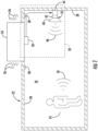
- a radar detection system 20 which is a radar presence detection system, is utilized in a building or structure 22 to detect the presence of a human 24 in a space 26 generally defined by an interior surface 28 of the building 22.
- the human detection is facilitated by the detection of oscillation that may be, for example, vital signs such as respiration and/or heartbeat.
- the radar presence detection system 20 includes an accelerometer 30, a radar 32, and a vital sign processing unit 44.
- the accelerometer 30 and the radar 32 are mounted to the surface 28, but at different locations.
- the accelerometer 30 may be mounted proximate to building equipment 34 of the building 22 known to emit background vibrations 36.
- the accelerometer 30 may be a non-contacting method of measuring acceleration such as an additional radar or ultrasonic device.
- Other examples of background vibration 36 relevant to the present disclosure may include vibrations caused by weather conditions such as wind, outside traffic and/or trains, and other sources.
- the accelerometer 30 is located between vibrational nodes 38 generally located upon the building surface 28.
- the vital sign processing unit may be an integral part of the radar electronics, and contained within a common housing of the radar 32.
- the radar detection system 20 is generally taught as a detection system for the presence of a human through the detection of human vital signs, the present disclosure is also applicable to detecting the vital signs of animals and the vibrations or rotation of machinery.
- the radar 32 of the presence detection system 20 may be configured to operate within a range of ten (10) GHz to about seventy-nine (79) GHz.
- the radar 32 may include an antenna 40, and a transceiver 42.
- monitoring waves or signals 48 which may be about 10 GHz microwaves, are transmitted by the transceiver 42 via the antenna 40.
- the transceiver 42 may comprise a transmitter and receiver that are entirely separate, or which may share hardware and software.
- the antenna 40 may comprise one or more physical antenna elements (i.e., phased array) that may be separate, for the transmitter and receiver respectively, or which may be combined for either or both the transmitter and receiver.
- the outgoing monitoring waves 48 may reflect off of the human 24 and return to the radar 32 as reflected waves 50 that are received by the transceiver 42 through the antenna 40, and generally processed and detected by the vital sign processing unit 44.
- the reflected waves 50 are indicative of a human respiration and/or a heartbeat, and may further include building background noise contributed by the building vibration 36 which may cause motion of either the human 24 or radar 32.
- the antenna 40 generally emits and receives the waves 48, 50.
- the transceiver 42 is configured to transmit and receive the waves 48, 50 via the antenna 40, and amplifies, and/or frequency-converts, the received reflected waves 50.
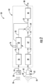
- the vital sign processing unit 44 may detect the reflected waves 50 (e.g., microwaves) by amplitude, frequency, or phase detection, convert the waves from analog to digital, and filter out background noise from, for example, the building vibration 36, thereby producing corrected vital sign waves, or a corrected vital sign signal, 52 (see FIG. 2 )
- the accelerometer 30 may be a three-axis accelerometer, hence outputting a three channel vibration wave signal 54 to the vital sign processing unit 44 for processing of each channel.
- the vital sign processing unit 44 may include a first analog-to digital converter (ADC) 56, a second ADC 58, an adaptive filter 60 (i.e., LMS), a low pass filter 62, a summation module 64 and a detector 66.
- ADC analog-to digital converter
- LMS adaptive filter 60
- the vibration wave signal 54 may be amplified by the accelerometer 30 prior to sending to the ADC 56.
- the reflected waves 50 are received by the transceiver 42 of the radar 32 via the antenna 40, may be amplified, and then sent to the ADC 58 as a reflected wave signal 68 for conversion from analog to digital.
- the ADC 56 is configured to send a digitized vibration signal 70 to the adaptive filter 60.
- the ADC 58 is configured to send a digitized reflected wave signal 72 to the filter 62.
- the filter 62 filters the signal 72 to a range of human vital signs.
- a normal heart rate may be 60 to 180 beats per minute equating to about one (1) to three (3) Hz
- a typical respiratory rate is about ten (10) to twenty (20) breaths per minute equating to about 0.15 to 0.3 Hz.
- any other harmonics and out-of-band noise can be filtered out by employing the filter 62.
- the incoming digitized reflected wave signal 72 is processed into an outgoing vital sign reflected wave signal 74.
- the adaptive filter 60 may be a long adaptive filter having sufficient taps 76 so that a full wave at the lowest respiration frequency (i.e., 0.15 Hz) may be accommodated. More specifically, the adaptive filter 60 facilitates the cancellation of broadband vibration, and not a specific number or range of harmonics. Therefore, the adaptive filter 60 includes a multitude of taps 76, wherein the number of taps 76 is not related to a number of harmonics. It is noted that the adaption rate of the filter 60 may be slow since the adaptive filter 60 may be computing a transfer function of the building 22 associated with the location of the accelerometer 30 relative to the radar 32. In one embodiment, the transfer function may be estimated once at the installation of the presence detection system 20 and used thereafter.
- the transfer function is updated during operation.
- the adaptive filter 60 may be a least-mean-square (LMS) filter.
- Other filter 60 examples may include Normalized Least-Mean-Square (NLMS), Recursive Least Squares (RLS), and Sample or Direct Matrix Inversion (DMI) filters.
- NLMS Normalized Least-Mean-Square
- RLS Recursive Least Squares
- DI Sample or Direct Matrix Inversion
- the adaptive filter 60 is configured to filter the vibration signal 70 to enable cancelling a broadband of vibration frequencies within the frequency range of human vital signs by outputting a focused vibration signal 78 associated with noise within the human vital sign frequency range(s).
- the summation module 64 is configured to receive the signals 74, 78, subtract the focused vibration signal 78 from the vital sign reflected wave signal 74, and output the corrected, or noise reduced, vital sign signal 52 to the detector 66.
- the focused vibration signal 78 may be produced as the output of a Finite Impulse Response (FIR) filter with adapted coefficients based on the vibration signal 70 and the corrected vital signal 52 using a LMS update.
- the FIR filter is effectively the transfer function from the vibration signal 70 to the vital sign reflected wave signal 74.
- the detector 66 is configured to evaluate the corrected vital sign signal 52, determine the presence of a human, and output an oscillation or presence signal 80 that may be indicative of the presence and/or non-presence of the human 24.
- FIR Finite Impulse Response
- the presence signal 80 may be used by any number of systems commonly applied in a building 22.
- the signal 80 may be used by a security system attempting to detect intrusions, by a heating and/or cooling system attempting to save energy when, for example, a building is vacant, and/or a safety or fire protection system attempting to locate people during a fire scenario.
- Other systems including building management systems may be further enhanced via the use of the presence detection system 20.
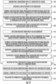
- a method of operating the presence detection system 20 is illustrated.
- a monitoring wave 48 is transmitted by a transceiver 42 of radar 32.
- a reflected wave 50 is received by the transceiver 42.
- a reflected wave signal 68 indicative of the reflected wave 50, is sent by the radar 32 to a first analog-to-digital converter 58 of a vital sign processing unit 44.
- a digitized reflected wave signal 72 associated with the reflected wave signal 68, is filtered by a filter 62 of the vital sign processing unit 44 to cancel a broadband of frequencies not within a targeted oscillation frequency range (e.g., vital sign frequency range).
- an oscillation reflected wave signal 74 (e.g., vital sign reflected wave signal) associated with the digitized reflected wave signal 72 is outputted by the filter 62.
- the detection and processing of building vibrations may occur simultaneously to the events of blocks 100 through 108. More specifically and at block 110, building vibrations are detected by an accelerometer 30. At block 112, a vibration wave signal 54 associated with the building vibration is sent by the accelerometer to a second ADC 56 of the vital sign processing unit 44. At block 114, a digitized vibration signal 70 associated with the vibration wave signal 54 is filtered by an adaptive filter 60 of the vital sign processing unit 44 to enable cancelation of a broadband of frequencies within the vital sign frequency range. At block 116, a transfer function associated with the location of the accelerometer 30 relative to the radar 32 is updated by the adaptive filter 60. At block 118, a focused vibration signal 78 associated with the digitized vibration signal 70 is outputted by the adaptive filter 60.
- the vital sign reflected wave signal 74 and the focused vibration signal 78 are received by a summation module 64.
- the summation module 64 subtracts the focused vibration signal 78 from the vital sign reflected wave signal 74.
- a corrected oscillation signal 52 (e.g., corrected vital sign signal) is sent by the summation module 64 to the detector 66 and to adaptive filter 60.
- the corrected vital sign signal is evaluated by the detector 66 to determine a human presence.
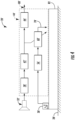
- a presence detection system 20' includes an accelerometer 30', a radar 32', a vital sign processing unit 44', and an actuator 82 mounted to a surface 28'.
- the accelerometer 30' may be attached to the actuator 82.
- the accelerometer 30', the radar 32', the vital sign processing unit 44', and the actuator 82 may be contained in a common housing and co-located.
- the actuator 82 is constructed and arranged to physically move the radar 32' in order to cancel out any noise produced by building vibration.
- the vital sign processing unit 44' may include a first analog-to digital converter (ADC) 56', a second ADC 58', an adaptive filter 60' (i.e., LMS), a low pass filter 62', and a detector 66'.
- the adaptive filter 60' outputs a focused vibration signal 78' to the actuator 82.
- the adaptive filter 60' is configured to drive the actuator 82 in an opposite motion to the sensed motion (i.e., vibration) of the surface 28', thereby effectively isolating the radar 32' from building vibration.
- Advantages and benefits of the present disclosure include an efficient, effective, and/or accurate radar human vital sign detection in the presence of complex vibration of the radar sensor from the mounting structure.
Landscapes
- Engineering & Computer Science (AREA)
- Health & Medical Sciences (AREA)
- Radar, Positioning & Navigation (AREA)
- Remote Sensing (AREA)
- Life Sciences & Earth Sciences (AREA)
- Physics & Mathematics (AREA)
- Computer Networks & Wireless Communication (AREA)
- General Physics & Mathematics (AREA)
- Biomedical Technology (AREA)
- Animal Behavior & Ethology (AREA)
- Biophysics (AREA)
- Pathology (AREA)
- Veterinary Medicine (AREA)
- Heart & Thoracic Surgery (AREA)
- Medical Informatics (AREA)
- Molecular Biology (AREA)
- Surgery (AREA)
- Public Health (AREA)
- General Health & Medical Sciences (AREA)
- Cardiology (AREA)
- Physiology (AREA)
- Radiology & Medical Imaging (AREA)
- Nuclear Medicine, Radiotherapy & Molecular Imaging (AREA)
- Pulmonology (AREA)
- Measurement Of The Respiration, Hearing Ability, Form, And Blood Characteristics Of Living Organisms (AREA)
Description
- The present disclosure relates to a detection system, and more particularly to a radar presence detection system.
- Utilization of relatively inexpensive radar to detect human presence through motion, heartbeat and/or respiration is an emerging technology. The same technology may also be used to monitor the heartbeat, respiration, or vital signs of any species of animal. Yet further, the technology may be used to detect unusual vibration of, for example, equipment. The radar is typically attached to a building wall or ceiling. Unfortunately, building vibration may contribute toward electronic noise that degrades the detection capability of vital signs or vibration, indicative of, for example, a human presence. Various means of isolating such noise from the radar is desirable.
-
WO 2016/038148 A1 discloses a method for sensing occupancy status within an automotive vehicle using a radar system, at least one sensor, processing circuitry, and an accelerometer. An occupancy status signal is produced based on at least one sensor signal and accelerometer data containing information regarding vibration or motion of said automotive vehicle. -
US 2010/141443 A1 discloses an in-container monitoring sensor system including an UWB radar intrusion detector positioned within a container, wherein a false alarm discriminator is also provided and analyses data from the radar and other sensors in order to output a signal indicating an intrusion based on the data analysed. -
US 2009/058711 A1 discloses a system for monitoring a container, including a radar sensor interoperably connected to a data interpretation device in order to detect security breaches, wherein motion-detection sensors are used to prevent false positives occurring. - According to a first aspect of the invention, there is provided a radar presence detection system configured to detect the presence of a human in a space defined by an interior surface of a building through the detection of an oscillation within the building, wherein the oscillation is a vital sign, the radar detection system comprising: an accelerometer attached to the building and configured to detect structural vibration waves; a radar configured to transmit a monitoring wave and receive a reflected wave; and a vital sign processing unit configured to receive a reflected wave signal from the radar indicative of the reflected wave, and a vibration wave signal indicative of the structural vibration wave, the processing unit including: a filter configured to receive a first signal indicative of the reflected wave signal and output a vital sign reflected wave signal which is a filtered reflected wave signal spanning a frequency range indicative of an oscillation within the building, an adaptive filter configured to receive a second signal indicative of the structural vibration wave signal and output a focused vibration signal spanning the frequency range for the cancellation of vibration noise, a summation module configured to receive the vital sign reflected wave signal and the focused vibration signal, subtract the focused vibration signal from the vital sign reflected wave signal, and output a corrected vital sign signal, and a detector configured to receive the corrected vital sign signal and output an oscillation signal indicative of at least the detection of the oscillation. The accelerometer and the radar are mounted to the interior surface of the building at different locations
- In the alternative or additional thereto, in the foregoing embodiment, the vital sign processing unit includes a first analog-to-digital converter configured to receive the reflected wave signal and output a digitized reflected wave signal as the first signal.
- In the alternative or additional thereto, in the foregoing embodiment, the vital sign processing unit includes a second analog-to-digital converter configured to receive the vibration wave signal and output a digitized vibration signal as the second signal.
- In the alternative or additional thereto, in the foregoing embodiment, the adaptive filter includes a plurality of taps with a sufficient number of taps so that a full wave at a minimum respiration frequency is accommodated.
- In the alternative or additional thereto, in the foregoing embodiment, the oscillation is at least one vital sign that includes at least one of a respiration rate and a heartbeat.
- The radar is remotely located from the accelerometer.
- In the alternative or additional thereto, in the foregoing embodiment, the radar presence detection system includes an actuator attached to the building and the accelerometer, wherein the actuator receives and is driven by the focused vibration signal to cancel vibration noise.
- In the alternative or additional thereto, in the foregoing embodiment, the adaptive filter is at least one of a LMS filter, a NLMS filter, a RLS filter, and a DMI filter.
- In the alternative or additional thereto, in the foregoing embodiment, the accelerometer is not located at any vibration node of the building.
- In the alternative or additional thereto, in the foregoing embodiment, the accelerometer is a three-axis accelerometer.
- A method of operating a radar presence detection system to detect the presence of a human in a space defined by an interior surface of a building according to another, non-limiting, embodiment includes transmitting a monitoring wave by a transceiver of a radar; receiving a reflected wave by the transceiver; sending a reflected wave signal indicative of the reflected wave and by the radar to a processing unit; filtering a digitized reflected wave signal associated with the reflected wave signal by a filter of the processing unit to cancel a broadband of frequencies not within a targeted oscillation frequency range; outputting an oscillation reflected wave signal associated with the digitized reflected wave signal by the filter; detecting building vibrations by an accelerometer, wherein the accelerometer is mounted to the interior surface of the building at a different location to the radar; sending a building vibration wave signal by the accelerometer to a second analog-to-digital converter of the processing unit; filtering a digitized vibration signal associated with the vibration wave signal by an adaptive filter of the processing unit to cancel a broadband of frequencies within the targeted oscillation frequency range; outputting a focused vibration signal associated with the digitized vibration signal by the adaptive filter; receiving the oscillation reflected wave signal and the focused vibration signal by a summation module; subtracting the focused vibration signal from the oscillation reflected wave signal; sending a corrected oscillation signal by the summation module to a detector; and evaluating the corrected oscillation signal by the detector to determine a presence.
- Additionally to the foregoing embodiment, the processing unit is a vital sign processing unit, the targeted oscillation frequency range is a vital sign frequency range, the oscillation reflected wave signal is a vital sign reflected wave signal, the corrected oscillation signal is a corrected vital sign signal.
- In the alternative or additionally thereto, in the foregoing embodiment, the presence is a human presence.
- In the alternative or additionally thereto, in the foregoing embodiment, the method includes computing a transfer function by the adaptive filter associated with the location of the accelerometer relative to the radar.
- In the alternative or additionally thereto, in the foregoing embodiment, the reflected wave signal is sent to a first analog-to-digital converter of the vital sign processing unit.
- The foregoing features and elements may be combined in various combinations without exclusivity, unless expressly indicated otherwise. These features and elements as well as the operation thereof will become more apparent in light of the following description and the accompanying drawings. However, it should be understood that the following description and drawings are intended to be exemplary in nature and non-limiting.
- Various features will become apparent to those skilled in the art from the following detailed description of the disclosed non-limiting embodiments. The drawings that accompany the detailed description can be briefly described as follows:
-
FIG. 1 is a schematic of a building incorporating a presence detection system as one, non-limiting, exemplary embodiment of the present disclosure; -
FIG. 2 is a schematic of the presence detection system; -
FIG. 3 is a flow chart of a method of operating the presence detection system; and -
FIG. 4 is a schematic of a second embodiment of a presence detection system. - Referring to
FIG. 1 , aradar detection system 20, which is a radar presence detection system, is utilized in a building orstructure 22 to detect the presence of a human 24 in aspace 26 generally defined by aninterior surface 28 of thebuilding 22. The human detection is facilitated by the detection of oscillation that may be, for example, vital signs such as respiration and/or heartbeat. The radarpresence detection system 20 includes anaccelerometer 30, aradar 32, and a vitalsign processing unit 44. Theaccelerometer 30 and theradar 32 are mounted to thesurface 28, but at different locations. In one example, theaccelerometer 30 may be mounted proximate to buildingequipment 34 of thebuilding 22 known to emitbackground vibrations 36. In another example, theaccelerometer 30 may be a non-contacting method of measuring acceleration such as an additional radar or ultrasonic device. Other examples ofbackground vibration 36 relevant to the present disclosure may include vibrations caused by weather conditions such as wind, outside traffic and/or trains, and other sources. Preferably, theaccelerometer 30 is located betweenvibrational nodes 38 generally located upon thebuilding surface 28. It is contemplated and understood that the vital sign processing unit may be an integral part of the radar electronics, and contained within a common housing of theradar 32. - It is contemplated and understood, that while the
radar detection system 20 is generally taught as a detection system for the presence of a human through the detection of human vital signs, the present disclosure is also applicable to detecting the vital signs of animals and the vibrations or rotation of machinery. - Referring to
FIGS. 1 and2 , theradar 32 of thepresence detection system 20 may be configured to operate within a range of ten (10) GHz to about seventy-nine (79) GHz. Theradar 32 may include anantenna 40, and atransceiver 42. In one example, monitoring waves orsignals 48, which may be about 10 GHz microwaves, are transmitted by thetransceiver 42 via theantenna 40. Thetransceiver 42 may comprise a transmitter and receiver that are entirely separate, or which may share hardware and software. Theantenna 40 may comprise one or more physical antenna elements (i.e., phased array) that may be separate, for the transmitter and receiver respectively, or which may be combined for either or both the transmitter and receiver. Theoutgoing monitoring waves 48 may reflect off of the human 24 and return to theradar 32 asreflected waves 50 that are received by thetransceiver 42 through theantenna 40, and generally processed and detected by the vitalsign processing unit 44. Thereflected waves 50 are indicative of a human respiration and/or a heartbeat, and may further include building background noise contributed by thebuilding vibration 36 which may cause motion of either the human 24 orradar 32. - The
antenna 40 generally emits and receives thewaves transceiver 42 is configured to transmit and receive thewaves antenna 40, and amplifies, and/or frequency-converts, the received reflectedwaves 50. The vitalsign processing unit 44 may detect the reflected waves 50 (e.g., microwaves) by amplitude, frequency, or phase detection, convert the waves from analog to digital, and filter out background noise from, for example, thebuilding vibration 36, thereby producing corrected vital sign waves, or a corrected vital sign signal, 52 (seeFIG. 2 ) - Referring to
FIG. 2 , theaccelerometer 30 may be a three-axis accelerometer, hence outputting a three channelvibration wave signal 54 to the vitalsign processing unit 44 for processing of each channel. The vitalsign processing unit 44 may include a first analog-to digital converter (ADC) 56, asecond ADC 58, an adaptive filter 60 (i.e., LMS), alow pass filter 62, asummation module 64 and adetector 66. In operation, thebuilding vibrations 36 are detected by theaccelerometer 30 and outputted as thevibration wave signal 54 to theADC 56 for conversion from analog to digital. Thevibration wave signal 54 may be amplified by theaccelerometer 30 prior to sending to theADC 56. Thereflected waves 50 are received by thetransceiver 42 of theradar 32 via theantenna 40, may be amplified, and then sent to theADC 58 as areflected wave signal 68 for conversion from analog to digital. - The
ADC 56 is configured to send a digitizedvibration signal 70 to theadaptive filter 60. Similarly, theADC 58 is configured to send a digitized reflectedwave signal 72 to thefilter 62. In operation, thefilter 62 filters thesignal 72 to a range of human vital signs. For example, a normal heart rate may be 60 to 180 beats per minute equating to about one (1) to three (3) Hz, and a typical respiratory rate is about ten (10) to twenty (20) breaths per minute equating to about 0.15 to 0.3 Hz. Accordingly, any other harmonics and out-of-band noise, other than that associated with the vital sign frequency range(s), can be filtered out by employing thefilter 62. When filtered, the incoming digitized reflectedwave signal 72 is processed into an outgoing vital sign reflectedwave signal 74. - The
adaptive filter 60 may be a long adaptive filter havingsufficient taps 76 so that a full wave at the lowest respiration frequency (i.e., 0.15 Hz) may be accommodated. More specifically, theadaptive filter 60 facilitates the cancellation of broadband vibration, and not a specific number or range of harmonics. Therefore, theadaptive filter 60 includes a multitude oftaps 76, wherein the number oftaps 76 is not related to a number of harmonics. It is noted that the adaption rate of thefilter 60 may be slow since theadaptive filter 60 may be computing a transfer function of thebuilding 22 associated with the location of theaccelerometer 30 relative to theradar 32. In one embodiment, the transfer function may be estimated once at the installation of thepresence detection system 20 and used thereafter. However, in another embodiment, the transfer function is updated during operation. One, non-limiting, example of theadaptive filter 60 may be a least-mean-square (LMS) filter.Other filter 60 examples may include Normalized Least-Mean-Square (NLMS), Recursive Least Squares (RLS), and Sample or Direct Matrix Inversion (DMI) filters. - The
adaptive filter 60 is configured to filter thevibration signal 70 to enable cancelling a broadband of vibration frequencies within the frequency range of human vital signs by outputting afocused vibration signal 78 associated with noise within the human vital sign frequency range(s). Thesummation module 64 is configured to receive thesignals vibration signal 78 from the vital sign reflectedwave signal 74, and output the corrected, or noise reduced,vital sign signal 52 to thedetector 66. The focusedvibration signal 78 may be produced as the output of a Finite Impulse Response (FIR) filter with adapted coefficients based on thevibration signal 70 and the correctedvital signal 52 using a LMS update. The FIR filter is effectively the transfer function from thevibration signal 70 to the vital sign reflectedwave signal 74. Thedetector 66 is configured to evaluate the correctedvital sign signal 52, determine the presence of a human, and output an oscillation orpresence signal 80 that may be indicative of the presence and/or non-presence of the human 24. - The
presence signal 80 may be used by any number of systems commonly applied in abuilding 22. For example, thesignal 80 may be used by a security system attempting to detect intrusions, by a heating and/or cooling system attempting to save energy when, for example, a building is vacant, and/or a safety or fire protection system attempting to locate people during a fire scenario. Other systems including building management systems may be further enhanced via the use of thepresence detection system 20. - Referring to
FIG. 3 , a method of operating thepresence detection system 20 is illustrated. Atblock 100, amonitoring wave 48 is transmitted by atransceiver 42 ofradar 32. Atblock 102, a reflectedwave 50 is received by thetransceiver 42. Atblock 104, a reflectedwave signal 68, indicative of the reflectedwave 50, is sent by theradar 32 to a first analog-to-digital converter 58 of a vitalsign processing unit 44. At block 106, a digitized reflectedwave signal 72, associated with the reflectedwave signal 68, is filtered by afilter 62 of the vitalsign processing unit 44 to cancel a broadband of frequencies not within a targeted oscillation frequency range (e.g., vital sign frequency range). Atblock 108, an oscillation reflected wave signal 74 (e.g., vital sign reflected wave signal) associated with the digitized reflectedwave signal 72 is outputted by thefilter 62. - The detection and processing of building vibrations may occur simultaneously to the events of
blocks 100 through 108. More specifically and atblock 110, building vibrations are detected by anaccelerometer 30. Atblock 112, avibration wave signal 54 associated with the building vibration is sent by the accelerometer to asecond ADC 56 of the vitalsign processing unit 44. Atblock 114, a digitizedvibration signal 70 associated with thevibration wave signal 54 is filtered by anadaptive filter 60 of the vitalsign processing unit 44 to enable cancelation of a broadband of frequencies within the vital sign frequency range. Atblock 116, a transfer function associated with the location of theaccelerometer 30 relative to theradar 32 is updated by theadaptive filter 60. Atblock 118, afocused vibration signal 78 associated with the digitizedvibration signal 70 is outputted by theadaptive filter 60. - At
block 120, the vital sign reflectedwave signal 74 and the focusedvibration signal 78 are received by asummation module 64. Atblock 122, thesummation module 64 subtracts the focusedvibration signal 78 from the vital sign reflectedwave signal 74. Atblock 124, a corrected oscillation signal 52 (e.g., corrected vital sign signal) is sent by thesummation module 64 to thedetector 66 and toadaptive filter 60. Atblock 126, the corrected vital sign signal is evaluated by thedetector 66 to determine a human presence. - Referring to
FIG. 4 , a second embodiment of a presence detection system is illustrated wherein like elements to the first embodiment have like identifying numbers except with the addition of a prime symbol suffix. A presence detection system 20' includes anaccelerometer 30', a radar 32', a vital sign processing unit 44', and anactuator 82 mounted to asurface 28'. Theaccelerometer 30' may be attached to theactuator 82. In an example not falling under the scope of protection, theaccelerometer 30', the radar 32', the vital sign processing unit 44', and theactuator 82 may be contained in a common housing and co-located. Theactuator 82 is constructed and arranged to physically move the radar 32' in order to cancel out any noise produced by building vibration. - The vital sign processing unit 44' may include a first analog-to digital converter (ADC) 56', a second ADC 58', an adaptive filter 60' (i.e., LMS), a low pass filter 62', and a detector 66'. The adaptive filter 60' outputs a focused vibration signal 78' to the
actuator 82. The adaptive filter 60' is configured to drive theactuator 82 in an opposite motion to the sensed motion (i.e., vibration) of thesurface 28', thereby effectively isolating the radar 32' from building vibration. - Advantages and benefits of the present disclosure include an efficient, effective, and/or accurate radar human vital sign detection in the presence of complex vibration of the radar sensor from the mounting structure.
- While the present disclosure is described with reference to exemplary embodiments, it will be understood by those skilled in the art that various changes may be made and equivalents may be substituted without departing from the scope of the present disclosure. In addition, various modifications may be applied to adapt the teachings of the present disclosure to particular situations, applications, and/or materials, without departing from the essential scope thereof. The present disclosure is thus not limited to the particular examples disclosed herein, but includes all embodiments falling within the scope of the appended claims.
Claims (14)
- A radar presence detection system (20) configured to detect the presence of a human in a space defined by an interior surface of a building through the detection of an oscillation within the building, wherein the oscillation is a vital sign, the radar detection system comprising:an accelerometer (30) attached to the building and configured to detect structural vibration waves;a radar (32) configured to transmit a monitoring wave (48) and receive a reflected wave (50); anda vital sign processing unit (44) configured to receive a reflected wave signal (68) from the radar indicative of the reflected wave (50), and a vibration wave signal (54) indicative of the structural vibration wave, the processing unit (44) including:a filter (62) configured to receive a first signal indicative of the reflected wave signal (68) and output a vital sign reflected wave signal (74) which is a filtered reflected wave signal spanning a frequency range indicative of an oscillation within the building,an adaptive filter (60) configured to receive a second signal indicative of the structural vibration wave signal (54) and output a focused vibration signal (78) spanning the frequency range for the cancellation of vibration noise,a summation module (64) configured to receive the vital sign reflected wave signal (74) and the focused vibration signal (78), subtract the focused vibration signal (78) from the vital sign reflected wave signal (74), and output a corrected vital sign signal (52), anda detector (66) configured to receive the corrected vital sign signal (52) and output an oscillation signal (80) indicative of at least the detection of the oscillation;wherein the accelerometer (30) and the radar (32) are mounted to the interior surface of the building at different locations.
- The radar presence detection system (20) set forth in claim 1, wherein the vital sign processing unit (44) includes a first analog-to-digital converter (56) configured to receive the reflected wave signal (74) and output a digitized reflected wave signal (72) as the first signal, optionally wherein the vital sign processing unit (44) includes a second analog-to-digital converter (58) configured to receive the vibration wave signal (54) and output a digitized vibration signal (70) as the second signal.
- The radar presence detection system (20) set forth in claim 1 or 2, wherein the adaptive filter (60) includes a plurality of taps (76) with a sufficient number of taps (76) so that a full wave at a minimum respiration frequency is accommodated.
- The radar presence detection system (20) set forth in claim 1, 2 or 3, wherein the oscillation includes at least one of a respiration rate and a heartbeat.
- The radar presence detection system (20) set forth in any preceding claim, wherein the radar (32) is remotely located from the accelerometer (30).
- The radar presence detection system set forth in any of claims 1 to 4 further comprising:
an actuator (82) attached to the building and the accelerometer (30), wherein the actuator (82) receives and is driven by the focused vibration signal (78) to cancel vibration noise. - The radar presence detection system (20) set forth in any preceding claim, wherein the adaptive filter (60) is at least one of a LMS filter, a NLMS filter, a RLS filter, and a DMI filter.
- The radar presence detection system (20) set forth in any preceding claim, wherein the accelerometer (30) is not located at any vibration node of the building.
- The radar presence detection system (20) set forth in any preceding claim, wherein the accelerometer (30) is a three-axis accelerometer.
- A method of operating a radar presence detection system (20) to detect the presence of a human in a space defined by an interior surface of a building, comprising:transmitting a monitoring wave (48) by a transceiver (42) of a radar (32);receiving a reflected wave by the transceiver (42);sending a reflected wave signal indicative of the reflected wave and by the radar (32) to a processing unit (44);filtering a digitized reflected wave signal (72) associated with the reflected wave signal by a filter (62) of the processing unit (44) to cancel a broadband of frequencies not within a targeted oscillation frequency range;outputting an oscillation reflected wave signal (74) associated with the digitized reflected wave signal (72) by the filter;detecting building vibrations by an accelerometer (30), wherein the accelerometer is mounted to the interior surface of the building at a different location to the radar (32);sending a building vibration wave signal (54) by the accelerometer (30) to a second analog-to-digital converter (58) of the processing unit (44);filtering a digitized vibration signal (70) associated with the vibration wave signal (54) by an adaptive filter (60) of the processing unit (44) to cancel a broadband of frequencies within the targeted oscillation frequency range;outputting a focused vibration signal (78) associated with the digitized vibration signal (70) by the adaptive filter (60);receiving the oscillation reflected wave signal (74) and the focused vibration signal (78) by a summation module (64);subtracting the focused vibration signal (78) from the oscillation reflected wave signal;sending a corrected oscillation signal (52) by the summation module (64) to a detector (66); andevaluating the corrected oscillation signal (52) by the detector (66) to determine a presence.
- The method set forth in claim 10. , wherein the processing unit is a vital sign processing unit (44), the targeted oscillation frequency range is a vital sign frequency range, the oscillation reflected wave signal is a vital sign reflected wave signal (74), the corrected oscillation signal is a corrected vital sign signal (52).
- The method set forth in claim 10 or 11, wherein the presence is a human presence.
- The method set forth in claim 10, 11 or 12 further comprising:
computing a transfer function by the adaptive filter (60) associated with the location of the accelerometer (30) relative to the radar (32). - The method set forth in claim 10, 11, 12 or 13 wherein the reflected wave signal (68) is sent to a first analog-to-digital converter (56) of the vital sign processing unit (44).
Applications Claiming Priority (2)
| Application Number | Priority Date | Filing Date | Title |
|---|---|---|---|
| US201762443354P | 2017-01-06 | 2017-01-06 | |
| PCT/US2018/012556 WO2018129294A1 (en) | 2017-01-06 | 2018-01-05 | Radar detection system |
Publications (2)
| Publication Number | Publication Date |
|---|---|
| EP3566073A1 EP3566073A1 (en) | 2019-11-13 |
| EP3566073B1 true EP3566073B1 (en) | 2024-06-12 |
Family
ID=61074544
Family Applications (1)
| Application Number | Title | Priority Date | Filing Date |
|---|---|---|---|
| EP18701962.5A Active EP3566073B1 (en) | 2017-01-06 | 2018-01-05 | Radar detection system |
Country Status (4)
| Country | Link |
|---|---|
| US (1) | US11428797B2 (en) |
| EP (1) | EP3566073B1 (en) |
| CN (1) | CN110168399B (en) |
| WO (1) | WO2018129294A1 (en) |
Families Citing this family (6)
| Publication number | Priority date | Publication date | Assignee | Title |
|---|---|---|---|---|
| US11448721B2 (en) * | 2019-06-25 | 2022-09-20 | Infineon Technologies Ag | In device interference mitigation using sensor fusion |
| JP7466998B2 (en) * | 2020-07-03 | 2024-04-15 | アルプスアルパイン株式会社 | Active Noise Control System |
| US12153119B2 (en) * | 2020-11-20 | 2024-11-26 | Carrier Corporation | System and method to detect presence using low-cost radar |
| EP4071496A1 (en) | 2021-04-06 | 2022-10-12 | Carrier Fire & Security EMEA BV | Method and system for detecting an object |
| EP4395350A4 (en) * | 2021-11-29 | 2024-12-18 | Samsung Electronics Co., Ltd. | Electronic device for autofocusing and method for operating same |
| CN119374187A (en) * | 2023-07-25 | 2025-01-28 | 青岛海尔空调器有限总公司 | Control method and device for reducing noise impact of air conditioner outdoor unit and air conditioner |
Family Cites Families (31)
| Publication number | Priority date | Publication date | Assignee | Title |
|---|---|---|---|---|
| FR2331102A1 (en) | 1975-11-07 | 1977-06-03 | Tacussel Maurice | METHOD AND INSTALLATION FOR THE REMOTE CONTROL OF A ROOM SURVEILLANCE RADAR DEVICE |
| US7811234B2 (en) | 2002-08-01 | 2010-10-12 | California Institute Of Technology | Remote-sensing method and device |
| US6816073B2 (en) | 2002-09-11 | 2004-11-09 | Northrop Grumman Corporation | Automatic detection and monitoring of perimeter physical movement |
| US7679545B2 (en) | 2004-08-05 | 2010-03-16 | Georgia Tech Research Corporation | Suppressing motion interference in a radar detection system |
| US7507203B2 (en) | 2004-09-21 | 2009-03-24 | Digital Signal Corporation | System and method for remotely monitoring physiological functions |
| US20060061504A1 (en) | 2004-09-23 | 2006-03-23 | The Regents Of The University Of California | Through wall detection and tracking system |
| EP2010935A4 (en) | 2006-04-25 | 2012-10-03 | Univ Mississippi | METHOD FOR DETECTING PEOPLE |
| US7916066B1 (en) | 2006-04-27 | 2011-03-29 | Josef Osterweil | Method and apparatus for a body position monitor and fall detector using radar |
| US7567200B1 (en) | 2006-04-27 | 2009-07-28 | Josef Osterweil | Method and apparatus for body position monitor and fall detect ion using radar |
| US20080211668A1 (en) | 2007-03-02 | 2008-09-04 | Dixon Walter V | Method and system to detect humans or animals within confined spaces with a low rate of false alarms |
| US7898455B2 (en) | 2007-07-17 | 2011-03-01 | Rosenbury Erwin T | Handheld instrument capable of measuring heartbeat and breathing motion at a distance |
| US20090058711A1 (en) * | 2007-08-30 | 2009-03-05 | Walter Vincent Dixon | Method of and system for monitoring security of containers |
| WO2009055728A1 (en) | 2007-10-24 | 2009-04-30 | Kirsen Technologies Corporation | A system and method for space control and remote monitoring |
| US20100152600A1 (en) | 2008-04-03 | 2010-06-17 | Kai Sensors, Inc. | Non-contact physiologic motion sensors and methods for use |
| JP2011519288A (en) | 2008-04-03 | 2011-07-07 | カイ メディカル、 インコーポレイテッド | Non-contact physiological motion sensor and method of use thereof |
| US8461989B2 (en) * | 2008-10-16 | 2013-06-11 | Lawrence Livermore National Security, Llc. | Smart container UWB sensor system for situational awareness of intrusion alarms |
| CN102317981B (en) * | 2009-02-11 | 2014-09-03 | 皇家飞利浦电子股份有限公司 | Motion detection system and method with null points |
| CA2789521A1 (en) | 2009-02-25 | 2010-09-02 | Xanthia Global Limited | Wireless physiology monitor |
| US8686362B2 (en) | 2009-05-01 | 2014-04-01 | Uchicago Argonne, Llc | Millimeter wave sensor for far-field standoff vibrometry |
| US7978124B2 (en) * | 2009-08-03 | 2011-07-12 | Raytheon Company | Method and system for motion compensation for hand held MTI radar sensor |
| WO2011075639A1 (en) | 2009-12-18 | 2011-06-23 | Christopher Gary Sentelle | Moving entity detection |
| US8264396B2 (en) | 2010-01-20 | 2012-09-11 | Honeywell International Inc. | Three dimensional noncontact motion sensor |
| WO2012078577A1 (en) | 2010-12-06 | 2012-06-14 | The University Of Memphis | Surveillance and tracking system and method |
| US9000973B2 (en) | 2011-04-29 | 2015-04-07 | The Invention Science Fund I, Llc | Personal electronic device with a micro-impulse radar |
| US8742935B2 (en) | 2011-06-30 | 2014-06-03 | General Electric Company | Radar based systems and methods for detecting a fallen person |
| JP5454593B2 (en) | 2012-01-26 | 2014-03-26 | トヨタ自動車株式会社 | Heart rate signal processing apparatus and heart rate signal processing method |
| US10401477B2 (en) | 2014-02-25 | 2019-09-03 | University Of Florida Research Foundation, Inc. | Method and apparatus for doppler radar signal recovery of target displacement |
| US9772401B2 (en) | 2014-03-17 | 2017-09-26 | Qualcomm Incorporated | Systems, methods, and apparatus for radar-based detection of objects in a predetermined space |
| RS20140247A1 (en) | 2014-05-14 | 2015-12-31 | Novelic D.O.O. | Radar sensor operating in millimetre wave frequency range for detection of signs of life and method of its operation |
| LU92541B1 (en) * | 2014-09-10 | 2016-03-11 | Iee Sarl | Radar sensing of vehicle occupancy |
| CN104644143A (en) * | 2015-03-09 | 2015-05-27 | 耿希华 | Non-contact life sign monitoring system |
-
2018
- 2018-01-05 US US16/475,893 patent/US11428797B2/en active Active
- 2018-01-05 CN CN201880006034.8A patent/CN110168399B/en active Active
- 2018-01-05 WO PCT/US2018/012556 patent/WO2018129294A1/en not_active Ceased
- 2018-01-05 EP EP18701962.5A patent/EP3566073B1/en active Active
Also Published As
| Publication number | Publication date |
|---|---|
| CN110168399B (en) | 2024-02-09 |
| CN110168399A (en) | 2019-08-23 |
| WO2018129294A1 (en) | 2018-07-12 |
| US11428797B2 (en) | 2022-08-30 |
| EP3566073A1 (en) | 2019-11-13 |
| US20190346550A1 (en) | 2019-11-14 |
Similar Documents
| Publication | Publication Date | Title |
|---|---|---|
| EP3566073B1 (en) | Radar detection system | |
| EP1714167B1 (en) | Method and apparatus for through-the-wall motion detection utilizing cw radar | |
| US9390605B2 (en) | Auxiliary device for a hazard alarm constructed as a point type detector for function monitoring of the hazard alarm, and an arrangement and method of monitoring using a device of this kind | |
| EP1991966B1 (en) | Universal quick mount wireless door sensor and method | |
| US7323979B2 (en) | Dual technology glass breakage detector | |
| CN104240422A (en) | Ultrasonic space sampling method based on range profile, monitoring anti-theft device and method | |
| US11789136B2 (en) | Radar presence sensor device | |
| US6337625B1 (en) | Intrusion detection process and device | |
| RU2007146988A (en) | SYSTEM AND METHOD FOR DETECTING INTRODUCTION | |
| KR101257873B1 (en) | Trespass detecting apparatus and system having the same | |
| CA2834298C (en) | A method and a system for supervising intruder alarm systems | |
| WO2008064032A2 (en) | Robust tactical unattended ground sensor networking | |
| KR20150100200A (en) | Apparatus for detecting multi-target of unmanned security monitoring system | |
| JP4573866B2 (en) | Intrusion detection system | |
| EP3543976B1 (en) | A method for increasing specificity of jamming detection in a home alarm system | |
| CA2167624C (en) | Structure-borne sound detector for break-in surveillance | |
| JPH01237483A (en) | Ultrasonic detector of invader | |
| JP2009099020A (en) | Microwave sensor | |
| KR102558865B1 (en) | How to detect at least one object around the vehicle | |
| JPH05210790A (en) | Wireless automatic fire alarm | |
| EP1095828A2 (en) | Intruder detection system for a motor vehicle | |
| EP1014325A1 (en) | Improvements in anti-intrusion systems against false-alarms | |
| KR200424396Y1 (en) | Dual random noise generation and line monitoring function of laser tapping prevention device | |
| RU101563U1 (en) | SECURITY COMPLEX | |
| HUP0900279A2 (en) | Anti intrusion arrangement |
Legal Events
| Date | Code | Title | Description |
|---|---|---|---|
| STAA | Information on the status of an ep patent application or granted ep patent |
Free format text: STATUS: UNKNOWN |
|
| STAA | Information on the status of an ep patent application or granted ep patent |
Free format text: STATUS: THE INTERNATIONAL PUBLICATION HAS BEEN MADE |
|
| PUAI | Public reference made under article 153(3) epc to a published international application that has entered the european phase |
Free format text: ORIGINAL CODE: 0009012 |
|
| STAA | Information on the status of an ep patent application or granted ep patent |
Free format text: STATUS: REQUEST FOR EXAMINATION WAS MADE |
|
| 17P | Request for examination filed |
Effective date: 20190611 |
|
| AK | Designated contracting states |
Kind code of ref document: A1 Designated state(s): AL AT BE BG CH CY CZ DE DK EE ES FI FR GB GR HR HU IE IS IT LI LT LU LV MC MK MT NL NO PL PT RO RS SE SI SK SM TR |
|
| AX | Request for extension of the european patent |
Extension state: BA ME |
|
| DAV | Request for validation of the european patent (deleted) | ||
| DAX | Request for extension of the european patent (deleted) | ||
| STAA | Information on the status of an ep patent application or granted ep patent |
Free format text: STATUS: EXAMINATION IS IN PROGRESS |
|
| 17Q | First examination report despatched |
Effective date: 20210805 |
|
| P01 | Opt-out of the competence of the unified patent court (upc) registered |
Effective date: 20230527 |
|
| GRAP | Despatch of communication of intention to grant a patent |
Free format text: ORIGINAL CODE: EPIDOSNIGR1 |
|
| STAA | Information on the status of an ep patent application or granted ep patent |
Free format text: STATUS: GRANT OF PATENT IS INTENDED |
|
| INTG | Intention to grant announced |
Effective date: 20240104 |
|
| GRAS | Grant fee paid |
Free format text: ORIGINAL CODE: EPIDOSNIGR3 |
|
| GRAA | (expected) grant |
Free format text: ORIGINAL CODE: 0009210 |
|
| STAA | Information on the status of an ep patent application or granted ep patent |
Free format text: STATUS: THE PATENT HAS BEEN GRANTED |
|
| RAP3 | Party data changed (applicant data changed or rights of an application transferred) |
Owner name: CARRIER CORPORATION |
|
| AK | Designated contracting states |
Kind code of ref document: B1 Designated state(s): AL AT BE BG CH CY CZ DE DK EE ES FI FR GB GR HR HU IE IS IT LI LT LU LV MC MK MT NL NO PL PT RO RS SE SI SK SM TR |
|
| REG | Reference to a national code |
Ref country code: GB Ref legal event code: FG4D |
|
| REG | Reference to a national code |
Ref country code: CH Ref legal event code: EP |
|
| REG | Reference to a national code |
Ref country code: IE Ref legal event code: FG4D |
|
| REG | Reference to a national code |
Ref country code: DE Ref legal event code: R096 Ref document number: 602018070479 Country of ref document: DE |
|
| REG | Reference to a national code |
Ref country code: NL Ref legal event code: FP |
|
| PG25 | Lapsed in a contracting state [announced via postgrant information from national office to epo] |
Ref country code: BG Free format text: LAPSE BECAUSE OF FAILURE TO SUBMIT A TRANSLATION OF THE DESCRIPTION OR TO PAY THE FEE WITHIN THE PRESCRIBED TIME-LIMIT Effective date: 20240612 |
|
| PG25 | Lapsed in a contracting state [announced via postgrant information from national office to epo] |
Ref country code: HR Free format text: LAPSE BECAUSE OF FAILURE TO SUBMIT A TRANSLATION OF THE DESCRIPTION OR TO PAY THE FEE WITHIN THE PRESCRIBED TIME-LIMIT Effective date: 20240612 Ref country code: FI Free format text: LAPSE BECAUSE OF FAILURE TO SUBMIT A TRANSLATION OF THE DESCRIPTION OR TO PAY THE FEE WITHIN THE PRESCRIBED TIME-LIMIT Effective date: 20240612 |
|
| REG | Reference to a national code |
Ref country code: LT Ref legal event code: MG9D |
|
| PG25 | Lapsed in a contracting state [announced via postgrant information from national office to epo] |
Ref country code: GR Free format text: LAPSE BECAUSE OF FAILURE TO SUBMIT A TRANSLATION OF THE DESCRIPTION OR TO PAY THE FEE WITHIN THE PRESCRIBED TIME-LIMIT Effective date: 20240913 |
|
| PG25 | Lapsed in a contracting state [announced via postgrant information from national office to epo] |
Ref country code: ES Free format text: LAPSE BECAUSE OF FAILURE TO SUBMIT A TRANSLATION OF THE DESCRIPTION OR TO PAY THE FEE WITHIN THE PRESCRIBED TIME-LIMIT Effective date: 20240612 |
|
| PG25 | Lapsed in a contracting state [announced via postgrant information from national office to epo] |
Ref country code: LV Free format text: LAPSE BECAUSE OF FAILURE TO SUBMIT A TRANSLATION OF THE DESCRIPTION OR TO PAY THE FEE WITHIN THE PRESCRIBED TIME-LIMIT Effective date: 20240612 |
|
| PG25 | Lapsed in a contracting state [announced via postgrant information from national office to epo] |
Ref country code: NO Free format text: LAPSE BECAUSE OF FAILURE TO SUBMIT A TRANSLATION OF THE DESCRIPTION OR TO PAY THE FEE WITHIN THE PRESCRIBED TIME-LIMIT Effective date: 20240912 Ref country code: LV Free format text: LAPSE BECAUSE OF FAILURE TO SUBMIT A TRANSLATION OF THE DESCRIPTION OR TO PAY THE FEE WITHIN THE PRESCRIBED TIME-LIMIT Effective date: 20240612 Ref country code: HR Free format text: LAPSE BECAUSE OF FAILURE TO SUBMIT A TRANSLATION OF THE DESCRIPTION OR TO PAY THE FEE WITHIN THE PRESCRIBED TIME-LIMIT Effective date: 20240612 Ref country code: GR Free format text: LAPSE BECAUSE OF FAILURE TO SUBMIT A TRANSLATION OF THE DESCRIPTION OR TO PAY THE FEE WITHIN THE PRESCRIBED TIME-LIMIT Effective date: 20240913 Ref country code: FI Free format text: LAPSE BECAUSE OF FAILURE TO SUBMIT A TRANSLATION OF THE DESCRIPTION OR TO PAY THE FEE WITHIN THE PRESCRIBED TIME-LIMIT Effective date: 20240612 Ref country code: ES Free format text: LAPSE BECAUSE OF FAILURE TO SUBMIT A TRANSLATION OF THE DESCRIPTION OR TO PAY THE FEE WITHIN THE PRESCRIBED TIME-LIMIT Effective date: 20240612 Ref country code: BG Free format text: LAPSE BECAUSE OF FAILURE TO SUBMIT A TRANSLATION OF THE DESCRIPTION OR TO PAY THE FEE WITHIN THE PRESCRIBED TIME-LIMIT Effective date: 20240612 Ref country code: RS Free format text: LAPSE BECAUSE OF FAILURE TO SUBMIT A TRANSLATION OF THE DESCRIPTION OR TO PAY THE FEE WITHIN THE PRESCRIBED TIME-LIMIT Effective date: 20240912 |
|
| REG | Reference to a national code |
Ref country code: AT Ref legal event code: MK05 Ref document number: 1694720 Country of ref document: AT Kind code of ref document: T Effective date: 20240612 |
|
| PG25 | Lapsed in a contracting state [announced via postgrant information from national office to epo] |
Ref country code: PT Free format text: LAPSE BECAUSE OF FAILURE TO SUBMIT A TRANSLATION OF THE DESCRIPTION OR TO PAY THE FEE WITHIN THE PRESCRIBED TIME-LIMIT Effective date: 20241014 |
|
| PG25 | Lapsed in a contracting state [announced via postgrant information from national office to epo] |
Ref country code: PT Free format text: LAPSE BECAUSE OF FAILURE TO SUBMIT A TRANSLATION OF THE DESCRIPTION OR TO PAY THE FEE WITHIN THE PRESCRIBED TIME-LIMIT Effective date: 20241014 |
|
| PG25 | Lapsed in a contracting state [announced via postgrant information from national office to epo] |
Ref country code: PL Free format text: LAPSE BECAUSE OF FAILURE TO SUBMIT A TRANSLATION OF THE DESCRIPTION OR TO PAY THE FEE WITHIN THE PRESCRIBED TIME-LIMIT Effective date: 20240612 |
|
| PG25 | Lapsed in a contracting state [announced via postgrant information from national office to epo] |
Ref country code: EE Free format text: LAPSE BECAUSE OF FAILURE TO SUBMIT A TRANSLATION OF THE DESCRIPTION OR TO PAY THE FEE WITHIN THE PRESCRIBED TIME-LIMIT Effective date: 20240612 |
|
| PG25 | Lapsed in a contracting state [announced via postgrant information from national office to epo] |
Ref country code: AT Free format text: LAPSE BECAUSE OF FAILURE TO SUBMIT A TRANSLATION OF THE DESCRIPTION OR TO PAY THE FEE WITHIN THE PRESCRIBED TIME-LIMIT Effective date: 20240612 Ref country code: IS Free format text: LAPSE BECAUSE OF FAILURE TO SUBMIT A TRANSLATION OF THE DESCRIPTION OR TO PAY THE FEE WITHIN THE PRESCRIBED TIME-LIMIT Effective date: 20241012 |
|
| PG25 | Lapsed in a contracting state [announced via postgrant information from national office to epo] |
Ref country code: CZ Free format text: LAPSE BECAUSE OF FAILURE TO SUBMIT A TRANSLATION OF THE DESCRIPTION OR TO PAY THE FEE WITHIN THE PRESCRIBED TIME-LIMIT Effective date: 20240612 |
|
| PG25 | Lapsed in a contracting state [announced via postgrant information from national office to epo] |
Ref country code: RO Free format text: LAPSE BECAUSE OF FAILURE TO SUBMIT A TRANSLATION OF THE DESCRIPTION OR TO PAY THE FEE WITHIN THE PRESCRIBED TIME-LIMIT Effective date: 20240612 Ref country code: SK Free format text: LAPSE BECAUSE OF FAILURE TO SUBMIT A TRANSLATION OF THE DESCRIPTION OR TO PAY THE FEE WITHIN THE PRESCRIBED TIME-LIMIT Effective date: 20240612 |
|
| PG25 | Lapsed in a contracting state [announced via postgrant information from national office to epo] |
Ref country code: SM Free format text: LAPSE BECAUSE OF FAILURE TO SUBMIT A TRANSLATION OF THE DESCRIPTION OR TO PAY THE FEE WITHIN THE PRESCRIBED TIME-LIMIT Effective date: 20240612 |
|
| PG25 | Lapsed in a contracting state [announced via postgrant information from national office to epo] |
Ref country code: SM Free format text: LAPSE BECAUSE OF FAILURE TO SUBMIT A TRANSLATION OF THE DESCRIPTION OR TO PAY THE FEE WITHIN THE PRESCRIBED TIME-LIMIT Effective date: 20240612 Ref country code: SK Free format text: LAPSE BECAUSE OF FAILURE TO SUBMIT A TRANSLATION OF THE DESCRIPTION OR TO PAY THE FEE WITHIN THE PRESCRIBED TIME-LIMIT Effective date: 20240612 Ref country code: RO Free format text: LAPSE BECAUSE OF FAILURE TO SUBMIT A TRANSLATION OF THE DESCRIPTION OR TO PAY THE FEE WITHIN THE PRESCRIBED TIME-LIMIT Effective date: 20240612 Ref country code: PL Free format text: LAPSE BECAUSE OF FAILURE TO SUBMIT A TRANSLATION OF THE DESCRIPTION OR TO PAY THE FEE WITHIN THE PRESCRIBED TIME-LIMIT Effective date: 20240612 Ref country code: IS Free format text: LAPSE BECAUSE OF FAILURE TO SUBMIT A TRANSLATION OF THE DESCRIPTION OR TO PAY THE FEE WITHIN THE PRESCRIBED TIME-LIMIT Effective date: 20241012 Ref country code: EE Free format text: LAPSE BECAUSE OF FAILURE TO SUBMIT A TRANSLATION OF THE DESCRIPTION OR TO PAY THE FEE WITHIN THE PRESCRIBED TIME-LIMIT Effective date: 20240612 Ref country code: CZ Free format text: LAPSE BECAUSE OF FAILURE TO SUBMIT A TRANSLATION OF THE DESCRIPTION OR TO PAY THE FEE WITHIN THE PRESCRIBED TIME-LIMIT Effective date: 20240612 Ref country code: AT Free format text: LAPSE BECAUSE OF FAILURE TO SUBMIT A TRANSLATION OF THE DESCRIPTION OR TO PAY THE FEE WITHIN THE PRESCRIBED TIME-LIMIT Effective date: 20240612 |
|
| PG25 | Lapsed in a contracting state [announced via postgrant information from national office to epo] |
Ref country code: IT Free format text: LAPSE BECAUSE OF FAILURE TO SUBMIT A TRANSLATION OF THE DESCRIPTION OR TO PAY THE FEE WITHIN THE PRESCRIBED TIME-LIMIT Effective date: 20240612 |
|
| REG | Reference to a national code |
Ref country code: DE Ref legal event code: R097 Ref document number: 602018070479 Country of ref document: DE |
|
| PGFP | Annual fee paid to national office [announced via postgrant information from national office to epo] |
Ref country code: DE Payment date: 20241218 Year of fee payment: 8 |
|
| PG25 | Lapsed in a contracting state [announced via postgrant information from national office to epo] |
Ref country code: DK Free format text: LAPSE BECAUSE OF FAILURE TO SUBMIT A TRANSLATION OF THE DESCRIPTION OR TO PAY THE FEE WITHIN THE PRESCRIBED TIME-LIMIT Effective date: 20240612 |
|
| PLBE | No opposition filed within time limit |
Free format text: ORIGINAL CODE: 0009261 |
|
| STAA | Information on the status of an ep patent application or granted ep patent |
Free format text: STATUS: NO OPPOSITION FILED WITHIN TIME LIMIT |
|
| 26N | No opposition filed |
Effective date: 20250313 |
|
| REG | Reference to a national code |
Ref country code: CH Ref legal event code: PL |
|
| PG25 | Lapsed in a contracting state [announced via postgrant information from national office to epo] |
Ref country code: SE Free format text: LAPSE BECAUSE OF FAILURE TO SUBMIT A TRANSLATION OF THE DESCRIPTION OR TO PAY THE FEE WITHIN THE PRESCRIBED TIME-LIMIT Effective date: 20240612 |
|
| PG25 | Lapsed in a contracting state [announced via postgrant information from national office to epo] |
Ref country code: MC Free format text: LAPSE BECAUSE OF FAILURE TO SUBMIT A TRANSLATION OF THE DESCRIPTION OR TO PAY THE FEE WITHIN THE PRESCRIBED TIME-LIMIT Effective date: 20240612 Ref country code: LU Free format text: LAPSE BECAUSE OF NON-PAYMENT OF DUE FEES Effective date: 20250105 |
|
| GBPC | Gb: european patent ceased through non-payment of renewal fee |
Effective date: 20250105 |
|
| PG25 | Lapsed in a contracting state [announced via postgrant information from national office to epo] |
Ref country code: GB Free format text: LAPSE BECAUSE OF NON-PAYMENT OF DUE FEES Effective date: 20250105 Ref country code: BE Free format text: LAPSE BECAUSE OF NON-PAYMENT OF DUE FEES Effective date: 20250131 |
|
| PG25 | Lapsed in a contracting state [announced via postgrant information from national office to epo] |
Ref country code: CH Free format text: LAPSE BECAUSE OF NON-PAYMENT OF DUE FEES Effective date: 20250131 |
|
| REG | Reference to a national code |
Ref country code: BE Ref legal event code: MM Effective date: 20250131 |
|
| PGFP | Annual fee paid to national office [announced via postgrant information from national office to epo] |
Ref country code: FR Payment date: 20251217 Year of fee payment: 9 Ref country code: NL Payment date: 20251217 Year of fee payment: 9 |
|
| PG25 | Lapsed in a contracting state [announced via postgrant information from national office to epo] |
Ref country code: IE Free format text: LAPSE BECAUSE OF NON-PAYMENT OF DUE FEES Effective date: 20250105 |