EP3565971B1 - Method and a system for generating fuel efficient force by accelerating object and using centrifugal force - Google Patents
Method and a system for generating fuel efficient force by accelerating object and using centrifugal force Download PDFInfo
- Publication number
- EP3565971B1 EP3565971B1 EP17838060.6A EP17838060A EP3565971B1 EP 3565971 B1 EP3565971 B1 EP 3565971B1 EP 17838060 A EP17838060 A EP 17838060A EP 3565971 B1 EP3565971 B1 EP 3565971B1
- Authority
- EP
- European Patent Office
- Prior art keywords
- looped track
- reaction engines
- reaction
- engines
- looped
- Prior art date
- Legal status (The legal status is an assumption and is not a legal conclusion. Google has not performed a legal analysis and makes no representation as to the accuracy of the status listed.)
- Active
Links
Images




Classifications
-
- F—MECHANICAL ENGINEERING; LIGHTING; HEATING; WEAPONS; BLASTING
- F03—MACHINES OR ENGINES FOR LIQUIDS; WIND, SPRING, OR WEIGHT MOTORS; PRODUCING MECHANICAL POWER OR A REACTIVE PROPULSIVE THRUST, NOT OTHERWISE PROVIDED FOR
- F03H—PRODUCING A REACTIVE PROPULSIVE THRUST, NOT OTHERWISE PROVIDED FOR
- F03H99/00—Subject matter not provided for in other groups of this subclass
-
- F—MECHANICAL ENGINEERING; LIGHTING; HEATING; WEAPONS; BLASTING
- F02—COMBUSTION ENGINES; HOT-GAS OR COMBUSTION-PRODUCT ENGINE PLANTS
- F02C—GAS-TURBINE PLANTS; AIR INTAKES FOR JET-PROPULSION PLANTS; CONTROLLING FUEL SUPPLY IN AIR-BREATHING JET-PROPULSION PLANTS
- F02C6/00—Plural gas-turbine plants; Combinations of gas-turbine plants with other apparatus; Adaptations of gas-turbine plants for special use
Definitions
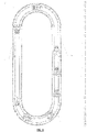
- An embodiment of the granted USPTO patent discloses a method for thrust generation comprising looped track that has two straight sides and two curved parts as shown in figure 1 , and a number of reaction engine vehicles that travel along the looped track in a programmed manner.
- electromagnetic design is utilized in a way so the movement is air cushioned and free of friction.
- the looped track consists of two straight paths. First straight path as shown in figure 1 part 1, is for the purpose of reaction engine vehicles to accelerate (acceleration achieved is totally independent of the looped track) and reach its top speed before going through the first curved part of the looped track.
- the reaction engine vehicle When the reaction engine vehicle travels through the first curved part of the looped track as shown in figure 1 part 2, it will inevitably experience a force away from the center of the curved path (centrifugal force) and this force is eventually transferred to the looped track.
- the second straight path of the looped track which is shown in figure 1 part 3 is used to decelerate the reaction engine vehicles (deceleration is done independent of the looped track).
- the reaction engines Eventually the reaction engines will pass the second curved path of the looped track which is shown in figure 1 part 4, with a low speed and reach the first straight path of the looped track and the cycle continues.
- the reaction engines are controlled by sensors and CPU to monitor and program the desired action.
- One of the main operational obstacles of this invention would be the friction that can be caused during the movement of the reaction engine vehicles along the looped track.
- the best method would be to utilize electromagnetic forces, repelling the permanent magnets attached to reaction engines that run through the looped track's different path's, in all directions so the permanent magnet of the reaction engine vehicle floats (air cushioned) within the looped track and runs without friction.
- the electromagnetic forces must not affect the running path of the reaction engine vehicles throughout the looped track. By utilizing such mechanism heat generation as well as sound and other unnecessary energy transformations are eliminated therefore higher efficiency can be achieved.
- the permanent magnet attached to the reaction engine vehicle will float (air cushioned) throughout the track path ( figure 3 part 1) during run.
- the number of wire turns and current passing through wires can be calculated by the Lorentz force formula with respect to the magnetic strength of the permanent magnet to achieve the necessary force to balance.
- the air gap (distance) between the permanent magnet and the wire coil Since the magnetic field strength (magnetic flux) is inversely proportional to the cubed of the air gap (distance away from the permanent magnet) so considerations also need to be taken with regards to this issue during design process.
- reaction engine that can be utilized is propellant method that uses electric motors to rotate its blades (duct fans used in RC airplanes could be one type). Also the electrical circuits and processors that are embedded inside the reaction engines that control and manage the movement of the reaction engine at different parts of the looped track need to receive electrical current. Another issue would be to provide the electric power required by the reaction engine vehicles by noncontact (wireless) methods. Since the reaction engine vehicles are constantly running along the path of looped track therefore we need a method to supply the necessary electric power required by them without involving complex wiring therefore it is recommended to utilize wireless means to supply the electric power from a power source to each reaction engine vehicle.
- any change in the magnetic field of a coil of wire will cause an emf to be induced in the coil.
- This emf induced is called induced emf and if the conductor circuit is closed, the current will also circulate through the circuit and this current is called induced current.
- one of the methods to create a change in magnetic field is to use alternating current in a primary coil of wire to create a changing magnetic field environment to meet Faraday's law requirement in order to create an emf in the secondary coil of wire in the proximity of primary coil of wire with alternating current.
- a current is induced in the secondary coil of wire wirelessly.
- the frequency of the alternating current in the primary coil must be set high enough to achieve the desired goal.
- a parachute system is attached to the reaction engines. Since the reaction engines decelerate at the second straight path of the looped track therefore it is essential to decelerate these reaction engines by means of air drag (to be efficient) and in order to achieve this goal a parachute mechanism is used and by actuating the parachute system to fold open, the cross sectional area of the reaction engine is increased therefore the drag force created will decelerate the reaction engine during its travel at the second straight path of the looped track, and eventually when the reaction engine reaches the end of the second straight path of the looped track its velocity will be at its minimal and the parachute is to be folded back and when the reaction engine reaches the first straight path of the looped track the reaction engine is ready to accelerate again.
- a number of sensors (for example 1 to 10) are attached to the looped track.
- these sensors will become activated and send a signal to the processor or CPU.
- the processor receives these signals and performs an operation based on the program that has been written for it and consequently issues a command for the corresponding reaction engine.
- the executive command is sent to the corresponding reaction engine by means of radio waves. Upon receipt of the command the corresponding reaction engine will execute the received order.
- the sensors that are attached to the looped track are wired to the input pins of the processor or CPU.
- the processor also has a number of output pins. When the processor receives a signal from the sensors attached to the looped track, and after processing and computing, the processor will activate one of the output pins with respect to the calculations and computing that has executed. This activated output pin then generates a predetermined radio frequency or encoded message via a frequency channel for the corresponding reaction engine.
- the output pins described above are wired to the circuits that can transmit the radio frequency which determines the correct command for the corresponding reaction engine. Also the reaction engines inside circuitry will receive the transmitted radio frequency and function accordingly.
- the force acquired by each reaction engine during acceleration which is the movement of reaction engines along the first straight path of the looped track needs to be adjustable so when the operator (as shown in figure 11 ) sets the desired force magnitude needed, all reaction engines running at the first straight path of the looped track must have a uniform force applied to them therefore having the same acceleration.
- reaction engines will be activated when aligning with sensor 1 which is attached to the starting point of the first straight path of the looped track and start accelerating. Once the reaction engines reach the sensor 2 (as shown in figure 7 ) which is the end of the first straight path of the looped track, they will be deactivated. During this period all reaction engines must have a uniform predetermined force applied to them and this can be achieved by sending a unique radio frequency to all reaction engines for the purpose of setting their predetermined force magnitude to be uniform during acceleration.
- sensor numbers 3 to 10 are attached to the looped track.
- the reaction engines arrive at the second straight path of the looped track they need to decelerate and reduce their speed which is done by activating the parachute system.
- the signal will be sent to the processor and the processor after rendering and calculating the speed of reaction engines will send the corresponding command to activate the parachute system of the reaction engine.
- the parachute of the corresponding reaction engine will fold back or become deactivated.
- the jet engine will have a speed of 29 m/s when it travels 10 meter and reaches the top point of the first straight path of the looped track.
- each jet engine consumes 76 grams of fuel during its acceleration phase.
- each jet engine consumes 76 grams of fuel during its acceleration along the first straight path of the looped track therefor to apply a force (centrifugal force) to the looped track in one second 9 jet engines will be utilized and by multiplying 76 grams of fuel consumption with the number of jet engines passing the first curved path of the looped track in one second we obtain a value of 684 grams of fuel consumed in one second by this example for this invention.
Landscapes
- Engineering & Computer Science (AREA)
- Chemical & Material Sciences (AREA)
- Combustion & Propulsion (AREA)
- Mechanical Engineering (AREA)
- General Engineering & Computer Science (AREA)
- Toys (AREA)
- Physical Or Chemical Processes And Apparatus (AREA)
- Centrifugal Separators (AREA)
Description
- With the growth of population globally and enhancement of humans life standards, the desire for transportation in all different sectors such as air, sea, cars, trucks, lorry, and etc for the purpose of delivery of goods and services as well as commutations has increased dramatically, and currently the methods used to provide the sufficient energy acquire mainly fossil fuels. Most of the engines used in propelling vehicles have low or medium efficiencies thereby most of the energies released by burning such fossil fuels are wasted to undesired forms such as heat and noise. Also by considering environmental issues the desire to cut fossil fuel consumptions is a necessity.
- By considering the rapid growth of population and production of all different forms of vehicles as well as fossil fuel and other energy generating limitations, therefore a very strong aspiration is felt to innovate a method and a system to maximize the fuel efficiency and by doing so reduce the fuel consumption in all sorts of vehicles.
- Wright brothers were the first who pioneered the invention of propeller force generating method and system which was also in full compliance of physics and Newtonian laws of motion which eventually lead to the invention of propeller airplanes. Later on Sir Frank Whittle invented jet engines which derived their thrust force by burning fuel and exhausting hot gasses at a very high speed to generate thrust force and is currently used in aviation industry prevalently. It is noticeable that the fuel consumption efficiency in the methods that has been invented and in use so far are low.
- Since the invention of jet engines, no other method and system for generating thrust force has been invented so far and mainly the inventions were to complete and improve the jet engine.
- This invention is an improvement and completion of my granted USPTO patent (
US 8272283 B2 ) to enhance fuel efficiency for generating thrust force and it comprises new and inventive steps with new claims. - An embodiment of the granted USPTO patent discloses a method for thrust generation comprising looped track that has two straight sides and two curved parts as shown in
figure 1 , and a number of reaction engine vehicles that travel along the looped track in a programmed manner. In order to eliminate friction between the reaction engine vehicles and the looped track electromagnetic design is utilized in a way so the movement is air cushioned and free of friction. As mentioned, the looped track consists of two straight paths. First straight path as shown infigure 1 part 1, is for the purpose of reaction engine vehicles to accelerate (acceleration achieved is totally independent of the looped track) and reach its top speed before going through the first curved part of the looped track. When the reaction engine vehicle travels through the first curved part of the looped track as shown infigure 1 part 2, it will inevitably experience a force away from the center of the curved path (centrifugal force) and this force is eventually transferred to the looped track. In order to cancel the reaction engine vehicle's effect on the opposite curved path of the looped track to reach a unidirectional force, the second straight path of the looped track which is shown infigure 1 part 3, is used to decelerate the reaction engine vehicles (deceleration is done independent of the looped track). Eventually the reaction engines will pass the second curved path of the looped track which is shown infigure 1 part 4, with a low speed and reach the first straight path of the looped track and the cycle continues. The reaction engines are controlled by sensors and CPU to monitor and program the desired action. - The above paragraph was a brief description of my granted USPTO patent and the descriptions below are the new and inventive steps taken to improve and complete the granted USPTO patent.
- It is an objective of the invention to provide a new and different method and apparatus for acceleration of said apparatus or a vehicle attached to it.
- The objective is solved by an apparatus according to
claim 1 and method according toclaim 10. Other embodiments are described in the dependent claims. - Embodiment of the invention will now be described, by ways of example only, with reference to the accompanying schematic drawings in which corresponding reference symbols indicate corresponding parts, and in which:
-
FIG. 1 is the top view of the mounted apparatus comprising reaction engine and looped track with its components. -
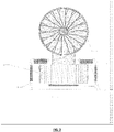
FIG. 2 is the perspective view of the apparatus with two looped tracks fixed together back to back and their respective reaction engines. -
FIG. 3 is the cross-sectional view of the looped track and reaction engine which illustrates the winding of wires around looped track and magnet of the reaction engine. -
FIG. 4 is the perspective view of the reaction engine equipped with parachute system. -
FIG. 5 is the perspective view of the reaction engine equipped with parachute system starting to fold open. -
FIG. 6 is the perspective view of the reaction engine equipped with parachute system folded open. -
FIG. 7 is the top view of the apparatus with sensors attached to the looped track. -
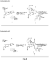
FIG. 8 shows the circuitry related to programming of this invention where the sensors that are attached to the looped track are wired to the input pins of this processor and this processor has outputs pins that convey the command to their corresponding reaction engine. -
FIG. 9 shows the circuitry for the output pins of the processor for transmitting a unique radio frequency or encoded radio channel to carry the desired command to be executed by the corresponding reaction engine. -
FIG. 10 shows the circuitry for the output pins of the processor for transmitting a unique radio frequency or encoded radio channel to carry the desired command to be executed by the corresponding reaction engine. -
FIG. 11 shows the circuitry to generate a unique radio frequency or encoded radio channel (as set by the operator) to be transmitted and received by all reaction engines to set a predetermined and uniform force magnitude during the acceleration phase which is the travelling of the reaction engines along the first straight path of the looped track. -
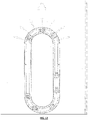
FIG. 12 is the top view of the mounted apparatus comprising reaction engine and looped track with its components and shows the force that has been generated by the looped track in different directions as a result of the reaction engines travelling at high speed along the first curved path of the looped track for which the resultant force generated by the looped track will eventually be a unidirectional force. - As shown in
figure 2 , in order to counter balance the above described mechanism and to avoid rattling (undesired shaking or vibrating moves) during continuous operation, two looped tacks are fixed together back to back and the movement of reaction engine vehicles running along these looped tracks must be in opposite directions i.e one in clockwise direction and the other in anticlockwise direction. Both sides must apply centrifugal force to the first curved part of their looped track to achieve a sufficient unidirectional force. - One of the main operational obstacles of this invention would be the friction that can be caused during the movement of the reaction engine vehicles along the looped track. In order to surmount this obstacle the best method would be to utilize electromagnetic forces, repelling the permanent magnets attached to reaction engines that run through the looped track's different path's, in all directions so the permanent magnet of the reaction engine vehicle floats (air cushioned) within the looped track and runs without friction. The electromagnetic forces must not affect the running path of the reaction engine vehicles throughout the looped track. By utilizing such mechanism heat generation as well as sound and other unnecessary energy transformations are eliminated therefore higher efficiency can be achieved. In order to avoid Eddy current it is best to use carbon fiber material for the looped track.
- As shown in
figure 3 by winding wires through different sections of the looped track (figure 3 part 2) and correct wiring to achieve desired current flow, the permanent magnet attached to the reaction engine vehicle (figure 3 part4) will float (air cushioned) throughout the track path (figure 3 part 1) during run. The number of wire turns and current passing through wires can be calculated by the Lorentz force formula with respect to the magnetic strength of the permanent magnet to achieve the necessary force to balance. When designing such system we must also take into considerations the air gap (distance) between the permanent magnet and the wire coil. Since the magnetic field strength (magnetic flux) is inversely proportional to the cubed of the air gap (distance away from the permanent magnet) so considerations also need to be taken with regards to this issue during design process. - We can utilize any kind of reaction engine for this invention and one of the types is jet engine. In order to manage the fueling of these jet engines we can design an automated pumping system at the second curved path of the looped track where the speed of the jet engines are at their lowest during their afore mentioned cycle and attach automated valves to the jet engine to receive the fuel through a short distance of the second curved path of the looped track, and then detach from the fueling system and continue their cycle.
- Another reaction engine that can be utilized is propellant method that uses electric motors to rotate its blades (duct fans used in RC airplanes could be one type). Also the electrical circuits and processors that are embedded inside the reaction engines that control and manage the movement of the reaction engine at different parts of the looped track need to receive electrical current. Another issue would be to provide the electric power required by the reaction engine vehicles by noncontact (wireless) methods. Since the reaction engine vehicles are constantly running along the path of looped track therefore we need a method to supply the necessary electric power required by them without involving complex wiring therefore it is recommended to utilize wireless means to supply the electric power from a power source to each reaction engine vehicle.
- According to Faraday's law any change in the magnetic field of a coil of wire will cause an emf to be induced in the coil. This emf induced is called induced emf and if the conductor circuit is closed, the current will also circulate through the circuit and this current is called induced current.
- As we know when a current passes through a wire a magnetic field is generated looping around that wire therefore one of the methods to create a change in magnetic field is to use alternating current in a primary coil of wire to create a changing magnetic field environment to meet Faraday's law requirement in order to create an emf in the secondary coil of wire in the proximity of primary coil of wire with alternating current. By this method a current is induced in the secondary coil of wire wirelessly. In order to increase the distance between the primary and secondary coil and still gain effective and viable current induction, the frequency of the alternating current in the primary coil must be set high enough to achieve the desired goal.
- In order to incorporate the Faraday's law to this invention we must create an alternating magnetic field along the entire path of the looped track by creating a high frequency alternating current from a DC source such as battery and by inverting the DC current to high frequency AC current and using coil of wire to generate the alternating magnetic field which can be conducted around the entire path of the looped track through by ferromagnetic alloys. Also we must attach a coil of wire to each of the reaction engine vehicles to receive the alternating current induced by the magnetic field, and when received, the alternating current can then be rectified and transformed to DC current and made available for consumption by electric circuits implemented in each reaction engine vehicles. The attached coil of wire to the reaction engine vehicle will remain within vicinity (noncontact) of the ferromagnetic alloy (alternating magnetic field supply source) during travel of the reaction engine vehicle along the path of the looped track.
- As shown in
figures 4 ,5 , and6 a parachute system is attached to the reaction engines. Since the reaction engines decelerate at the second straight path of the looped track therefore it is essential to decelerate these reaction engines by means of air drag (to be efficient) and in order to achieve this goal a parachute mechanism is used and by actuating the parachute system to fold open, the cross sectional area of the reaction engine is increased therefore the drag force created will decelerate the reaction engine during its travel at the second straight path of the looped track, and eventually when the reaction engine reaches the end of the second straight path of the looped track its velocity will be at its minimal and the parachute is to be folded back and when the reaction engine reaches the first straight path of the looped track the reaction engine is ready to accelerate again. - Since these reaction engines operate differently at different parts of the looped track for example the reaction engine accelerates at the first straight path of the looped track and decelerates at the second straight path of the looped track by actuating their parachute mechanism, and since the movement of these reaction engines along the looped track are independent of the looped track therefore sensors are needed to be attached to different parts of the looped track to monitor each reaction engine accordingly with respect to its position along the looped track and the information obtained by these sensors are processed by a CPU or processor which is programmed and then the computed function is transmitted to the corresponding reaction engine by means of radio waves and eventually the corresponding reaction engine will execute the command sent by processor.
- As shown in
figure 7 a number of sensors (for example 1 to 10) are attached to the looped track. When the reaction engines align with these sensors during their movement along the looped track, these sensors will become activated and send a signal to the processor or CPU. Eventually the processor receives these signals and performs an operation based on the program that has been written for it and consequently issues a command for the corresponding reaction engine. The executive command is sent to the corresponding reaction engine by means of radio waves. Upon receipt of the command the corresponding reaction engine will execute the received order. - As shown in
figure 8 the sensors that are attached to the looped track are wired to the input pins of the processor or CPU. The processor also has a number of output pins. When the processor receives a signal from the sensors attached to the looped track, and after processing and computing, the processor will activate one of the output pins with respect to the calculations and computing that has executed. This activated output pin then generates a predetermined radio frequency or encoded message via a frequency channel for the corresponding reaction engine. Since a number of reaction engines are moving along the looped track and also a number of command orders are needed to control the movement of reaction engines along different parts of the looped track, therefore accordingly sufficient number of output pins are required to send the correct command with respect to the reaction engines position along the looped track to its corresponding reaction engine. To avoid interference either different radiofrequency for each output pin is required or by encoding each output pin and using one frequency channel we can transmit the correct command to each reaction engine separately and securely. - As shown in
figures 9 and10 , the output pins described above are wired to the circuits that can transmit the radio frequency which determines the correct command for the corresponding reaction engine. Also the reaction engines inside circuitry will receive the transmitted radio frequency and function accordingly. - In order to have the privilege of adjusting the thrust force generated by this invention, the force acquired by each reaction engine during acceleration which is the movement of reaction engines along the first straight path of the looped track needs to be adjustable so when the operator (as shown in
figure 11 ) sets the desired force magnitude needed, all reaction engines running at the first straight path of the looped track must have a uniform force applied to them therefore having the same acceleration. - As shown in
figure 7 reaction engines will be activated when aligning withsensor 1 which is attached to the starting point of the first straight path of the looped track and start accelerating. Once the reaction engines reach the sensor 2 (as shown infigure 7 ) which is the end of the first straight path of the looped track, they will be deactivated. During this period all reaction engines must have a uniform predetermined force applied to them and this can be achieved by sending a unique radio frequency to all reaction engines for the purpose of setting their predetermined force magnitude to be uniform during acceleration. - As shown in
figure 7 sensor numbers 3 to 10 are attached to the looped track. When the reaction engines arrive at the second straight path of the looped track they need to decelerate and reduce their speed which is done by activating the parachute system. Once the reaction engines pass the sensors attached to the second straight path of the looped track the signal will be sent to the processor and the processor after rendering and calculating the speed of reaction engines will send the corresponding command to activate the parachute system of the reaction engine. When the reaction engine reaches the bottom part of the second straight path wheresensor number 10 according tofigure 7 is attached to the looped track, the parachute of the corresponding reaction engine will fold back or become deactivated. - Following is an example and analysis of the invention with regards to its fuel efficiency:
Consider a looped track with its first and second straight paths length to be 10 meters and its first and second curved paths to have a diameter of 2 meters. - Consider a reaction engine of jet engine type with the following specifications:
- Manufacturer: WILL:BR model FJ44
- Weight: 202 Kg
- Diameter: 0.5 meters
- Length: 1 meter
- Thrust force: 8500 Newton
- Specific fuel consumption (SFC): 12.89 g/(KN.s) grams per kilo Newton second
- (Note that specific fuel consumption (SFC) is an index for fuel efficiency)
- Consider the jet engine having a force of 8500 Newton accelerating along the first straight path of the looped track which is 10 meters in this example.

- Since v2 = 2.a.s
- Where:
- v = velocity of jet engine.
- a = acceleration of the jet engine.
- s = distance travelled by jet engine which in this example is 10 meters.
- Therefore by considering the above formula the jet engine will have a speed of 29 m/s when it travels 10 meter and reaches the top point of the first straight path of the looped track.
- Since v = a.t where t is time in seconds therefore it takes 0.69 seconds for the jet engine to travel 10 meters of the first straight path of the looped track.
- Since the specific fuel consumption (SFC) of the jet engine used in this example is 12.89 g/(KN.s) and the thrust force of this jet engine is 8500 Newton therefore each of these jet engines used in this example will consume 110 grams of fuel in one second.
- Now since the jet engine travels the first straight path of the looped track in 0.69 seconds therefore each jet engine consumes 76 grams of fuel during its acceleration phase.
- By considering the diameter of the first curved path of the looped track to be 2 meters and the speed in which the jet engine travels along the first curved part of the looped track as calculated above to be 29 m/s therefore it takes 0.11 second for the jet engine to travel along the first curved part of the looped track.
- By considering the time 0.11 seconds that takes for the jet engine to travel through the first curved path of the looped track, it takes 9 jet engines to travel at a continues paste in one second through the first curved path of the looped track.
- As mentioned above each jet engine consumes 76 grams of fuel during its acceleration along the first straight path of the looped track therefor to apply a force (centrifugal force) to the looped track in one second 9 jet engines will be utilized and by multiplying 76 grams of fuel consumption with the number of jet engines passing the first curved path of the looped track in one second we obtain a value of 684 grams of fuel consumed in one second by this example for this invention.
- By considering the formula centrifugal force = m.v2/r where m is the mass of each jet engine in Kg and v is the velocity of each jet engine in m/s and r is the radius of the curved path of the looped track in meters, the force that each jet engine exerts on the looped track while travelling through the first curved path of the looped track is calculated to be 169,882 Newton or approximately 170 KN.
- Since the force applied to the looped track by the reaction engines travelling through the first curved path of the looped track is sinusoidal therefore the RMS value of this force is derived by the formula

- Since for the deceleration of these jet engines we rely on parachutes therefore fuel is not consumed for that phase where the jet engines travel through the second straight path of the looped track and also since the speed of jet engine's travel during the second curved path of the looped track is relatively low so we ignore any opposite forces and obtain a unidirectional force by this invention.
- From the above calculations we were able to achieve 119 KN force in one second by this example for this invention and consumed 684 grams of fuel in one second. The specific fuel consumption (SFC) is therefore calculated to be 5.74 g/(KN.s) or approximately 6 grams per Kilo Newton second.
- As can be seen the specific fuel consumption (SFC) of the jet engines used for this example were 12.89 g/(KN.s) which was derived from its manufacturer and this invention generated a thrust force with specific fuel consumption (SFC) of 6 g/(KN.s) which is much less and more fuel efficient.
Claims (10)
- Apparatus for generating a unidirectional force comprising a first looped track and a plurality of reaction engines, and wherein the first looped track comprises a first straight path, a first curved path, a second straight path, and a second curved path and the reaction engines move along the different paths of the first looped track, wherein said reaction engines are configured to operate according to the following steps a) to d):a) each of said plurality of reaction engines in the first looped track is activated and accelerated in the first straight path of the first looped track with a controlled predetermined force magnitude in order to gain kinetic energy and once the said reaction engines reach the end of the first straight path of the first looped track their predetermined force will be deactivated and,b) each of said plurality of reaction engines in the first looped track which has gained said kinetic energy will enter the first curved path of the first looped track with a high velocity and travel along this path and exert as a result of the reaction engines movement along the first curved path of the first looped track a unidirectional force to the looped track and,c) each of said plurality of reaction engines in the first looped track is decelerated along the second straight path of the first looped track by means of drag forces acting against the reaction engines by activating a parachute system, and once the reaction engines reach the end of the second straight path of the first looped track having a low velocity the parachute system will fold back, and,d) each of said plurality of reaction engines in the first looped track will move along the second curved path of the first looped track with a low velocity and will be positioned at the stage at the beginning of step a) again and such that the steps a) to d) are carried out for each of said plurality of reaction engines in the first looped track cyclic such that said plurality of reaction engines travel around the first looped track and accelerate said apparatus;wherein a second looped track is fixed to the first looped track back to back and wherein said plurality of reaction engines in the second looped track is configured to operate analogous to steps a) to d) in said second looped track such that those of said plurality of reaction engines running along the first looped track move in an opposite direction than those of said plurality of reaction engines running along said second looped track in order to achieve a combined unidirectional force acting on said apparatus.
- Apparatus according to claim 1, further comprising wires wound around different sections of each looped track with electrical current flowing through it, and also the said plurality of reaction engines comprise a permanent magnet each therefore the said plurality of reaction engines will be floating air cushioned throughout the different paths of each looped track during run.
- Apparatus according to any one of the preceding claims, further comprising an automated fuel pumping system at the second curved path of each looped track where the speed of the said plurality of the reaction engines are at their lowest during their afore mentioned cycle according to steps a) to d) and wherein the said plurality of the reaction engines each comprise an automated valve to receive the fuel while moving along the second curved path of each looped track, and then detach from the fuel pumping system and continue their cycle.
- Apparatus according to any one of the preceding claims, wherein each looped track comprises a ferromagnetic coil of wire which conducts high frequency alternating current to generate an alternating magnetic field along the different paths of the said looped track and wherein each of said plurality of reaction engines further comprises a coil of wire to receive the alternating current induced by the alternating magnetic field, which can then be rectified and transformed to DC current and made available for consumption by electric circuits implemented in each of the said plurality of reaction engines.
- Apparatus according to any one of the preceding claims, wherein each looped track comprises a number of sensors alongside it such that said plurality of reaction engines moving along the different paths of the looped track pass these sensors that are attached to the looped track, wherein when one of said plurality of reaction engines aligns with any of the sensors attached to the looped track, that sensor then sends a signal to a processing unit, the processing unit will then process the received signal, and wherein a command issued for the corresponding reaction engine to be executed is transmitted by radio waves from the processing unit to the corresponding reaction engine
- Apparatus according to claim 5, wherein when one of said reaction engines arrives at said second straight path of the lopped track, it passes a sensor attached to the second straight path of the looped track, a signal will be sent to the processing unit and the processing unit after rendering and calculating the speed of said one of said reaction engines will send the corresponding command to activate the parachute system of said one of said reaction engines and, when said one of said reaction engines reaches the end of the second straight path where another sensor is attached to the looped track, the processing unit sends a command to deactivate the parachute system of said corresponding one of said reaction engines.
- A system according to claim 5, where the sensorsthat are attached to the looped track are wired to input pins of the processing unit, wherein the processing unit also has a number of output pins, such that the processing unit after receiving a signal from the sensors attached to the looped track, and after processing and computing will activate one of the output pins with respect to the calculations and computations executed, such that this activated output pin then generates a predetermined radio frequency or encoded message via a frequency channel for the corresponding reaction engine, wherein for avoidance of interference either different radio frequency for each output pin is generated or a different encoding for each output pin is used for transmitting the correct command to each reaction engine separately and securely.
- Apparatus according to any one of the preceding claims, wherein in order to adjust the thrust force generated according to an operator's desire a unique radio frequency is used for the purpose of setting the force applied by each of said plurality of reaction engines and their acceleration to be uniform such that all reaction engines running at the first straight path of each looped track have a uniform force magnitude applied to them.
- Method for generating a unidirectional force on an apparatus comprising a first looped track and a plurality of reaction engines, and wherein the first looped track comprises a first straight path, a first curved path, a second straight path, and a second curved path and wherein the reaction engines in the first looped track move along the different paths of the first looped track with the following steps:a) wherein each of said plurality of reaction engines in the first looped track is activated and accelerate in the first straight path of the first looped track with a predetermined force magnitude in order to gain kinetic energy and once the said reaction engines reach the end of the first straight path of the first looped track, their predetermined force will be deactivated and,b) wherein each of said plurality of reaction engines which has gained said kinetic energy will enter the first curved path of the first looped track with a high velocity and travel along this path and exert as a result of the reaction engines movement along the first curved path of the first looped track a unidirectional force to the looped track and,c) wherein each of said plurality of reaction engines is decelerated along the second straight path of the first looped track by means of drag forces acting against the reaction engines by activating a parachute system, and once the reaction engines reach the end of the second straight path of the first looped track having a low velocity the parachute system will fold back, and,d) wherein each of said plurality of reaction engines will move along the second curved path of the first looped track with a low velocity and will be positioned at the stage at the beginning of step a) again and wherein the steps a) to d) are carried out for each of said plurality of reaction engines cyclic such that said plurality of reaction engines travel around the first looped track and accelerate said apparatus,wherein a second plurality of reaction engines is operated analogous to steps a) to d) in a second looped track which is fixed to the first looped track back to back and wherein those of said plurality of reaction engines running along the first looped track move in an opposite direction than those of said plurality of reaction engines running along said second looped track in order to achieve a combined unidirectional force acting on said apparatus.
- Method according to claim 9, wherein when one of said reaction engines arrives at said second straight path of the looped track, it passes a sensor attached to the second straight path of the looped track, a signal will be sent to a processing unit and the processing unit after rendering and calculating the speed of said one of said reaction engines sends a corresponding command to activate the parachute system of said one of said reaction engines, and when said one of said reaction engines reaches the end of the second straight path where another sensor is attached to the looped track, the processing unit sends a command to deactivate the parachute system of said corresponding one of said reaction engines.
Applications Claiming Priority (2)
| Application Number | Priority Date | Filing Date | Title |
|---|---|---|---|
| IR13953010208 | 2016-11-16 | ||
| PCT/IB2017/001398 WO2018091962A2 (en) | 2016-11-16 | 2017-11-15 | Method and a system for generating fuel efficient force by accelerating object and using centrifugal force |
Publications (3)
| Publication Number | Publication Date |
|---|---|
| EP3565971A2 EP3565971A2 (en) | 2019-11-13 |
| EP3565971B1 true EP3565971B1 (en) | 2022-12-14 |
| EP3565971B8 EP3565971B8 (en) | 2023-01-25 |
Family
ID=83264666
Family Applications (1)
| Application Number | Title | Priority Date | Filing Date |
|---|---|---|---|
| EP17838060.6A Active EP3565971B8 (en) | 2016-11-16 | 2017-11-15 | Method and a system for generating fuel efficient force by accelerating object and using centrifugal force |
Country Status (3)
| Country | Link |
|---|---|
| EP (1) | EP3565971B8 (en) |
| ES (1) | ES2939844T3 (en) |
| WO (1) | WO2018091962A2 (en) |
Families Citing this family (1)
| Publication number | Priority date | Publication date | Assignee | Title |
|---|---|---|---|---|
| WO2025044049A1 (en) * | 2024-01-23 | 2025-03-06 | 张敬 | Elliptical orbit thruster |
Family Cites Families (2)
| Publication number | Priority date | Publication date | Assignee | Title |
|---|---|---|---|---|
| US8272283B2 (en) | 2008-02-25 | 2012-09-25 | Hossain Vafaey | Method and system for vibrating an object using centrifugal force |
| GR20100100348A (en) * | 2010-06-17 | 2012-01-31 | Γρηγοριος Σπυριδων Καραμητσος | Mechanism of double inertial propulsion |
-
2017
- 2017-11-15 WO PCT/IB2017/001398 patent/WO2018091962A2/en not_active Ceased
- 2017-11-15 EP EP17838060.6A patent/EP3565971B8/en active Active
- 2017-11-15 ES ES17838060T patent/ES2939844T3/en active Active
Also Published As
| Publication number | Publication date |
|---|---|
| EP3565971A2 (en) | 2019-11-13 |
| ES2939844T3 (en) | 2023-04-27 |
| WO2018091962A3 (en) | 2018-07-05 |
| WO2018091962A2 (en) | 2018-05-24 |
| EP3565971B8 (en) | 2023-01-25 |
| WO2018091962A4 (en) | 2018-09-20 |
Similar Documents
| Publication | Publication Date | Title |
|---|---|---|
| US10246266B2 (en) | Method for controlling the normal force of a transport unit of a long stator linear motor | |
| US9325220B2 (en) | Propulsion and control for a magnetically lifted vehicle | |
| US9254759B1 (en) | Propulsion and control for a magnetically lifted vehicle | |
| EP3471996B1 (en) | Magnetic suspension for a vehicle | |
| CN103057722A (en) | Active maglev electromagnetic catapult | |
| CN103522912A (en) | Magnetic flux feedback suspension control method and device of EMS type low-speed aerotrain | |
| EP3565971B1 (en) | Method and a system for generating fuel efficient force by accelerating object and using centrifugal force | |
| JP2017525325A (en) | Propulsion and control for magnetically levitated vehicles | |
| JP6730258B2 (en) | Levitation control system for transportation system | |
| CN103874850B (en) | Efficient Turbine | |
| CN205429917U (en) | Pole change is apart from growing elementary bilateral linear induction motor | |
| WO2007108586A1 (en) | System of railway vehicle using linear motor and non-contact electric power supply system | |
| CN101870299B (en) | Motor train unit auxiliary turning combination structure and auxiliary turning method | |
| US20200412200A1 (en) | Linear generator | |
| CN108809042A (en) | Linear motor based on radial magnetic tube | |
| Zhu et al. | A suspension damping enhancement method based on permanent magnet damping conductive plate for superconducting Maglev sled | |
| KR101999790B1 (en) | Maglev train having energy havester and infrastructure-system | |
| GB2550574A (en) | Drive arrangement | |
| CN103895520B (en) | Line inductance electromotor brake control method is used in a kind of traction | |
| CN102120457A (en) | Maglev galloping train device | |
| Esfahanian et al. | Performance analysis and force components improvement of an tubular linear induction motor used in a novel magnetic train by 3-D FEM | |
| Mok et al. | Analysis on dynamics characteristics of maglev with loop type linear synchronous motor section change algorithm using electro-mechanical co-simulation | |
| US20250075439A1 (en) | A switch for vehicles | |
| Sneha et al. | CELSM MAGNETIC LEVITATION SYSTEM CONTROL USING FSMC-PID | |
| Brakensiek et al. | Simulation and Implementation of a Curve Run of a Magnetic Levitated Transportation Vehicle |
Legal Events
| Date | Code | Title | Description |
|---|---|---|---|
| STAA | Information on the status of an ep patent application or granted ep patent |
Free format text: STATUS: UNKNOWN |
|
| STAA | Information on the status of an ep patent application or granted ep patent |
Free format text: STATUS: THE INTERNATIONAL PUBLICATION HAS BEEN MADE |
|
| PUAI | Public reference made under article 153(3) epc to a published international application that has entered the european phase |
Free format text: ORIGINAL CODE: 0009012 |
|
| STAA | Information on the status of an ep patent application or granted ep patent |
Free format text: STATUS: REQUEST FOR EXAMINATION WAS MADE |
|
| 17P | Request for examination filed |
Effective date: 20190912 |
|
| AK | Designated contracting states |
Kind code of ref document: A2 Designated state(s): AL AT BE BG CH CY CZ DE DK EE ES FI FR GB GR HR HU IE IS IT LI LT LU LV MC MK MT NL NO PL PT RO RS SE SI SK SM TR |
|
| AX | Request for extension of the european patent |
Extension state: BA ME |
|
| RAP1 | Party data changed (applicant data changed or rights of an application transferred) |
Owner name: BAHMANI, MOHSEN |
|
| RIN1 | Information on inventor provided before grant (corrected) |
Inventor name: VAFAEY, HOSSAIN |
|
| DAV | Request for validation of the european patent (deleted) | ||
| DAX | Request for extension of the european patent (deleted) | ||
| STAA | Information on the status of an ep patent application or granted ep patent |
Free format text: STATUS: EXAMINATION IS IN PROGRESS |
|
| 17Q | First examination report despatched |
Effective date: 20220103 |
|
| GRAP | Despatch of communication of intention to grant a patent |
Free format text: ORIGINAL CODE: EPIDOSNIGR1 |
|
| STAA | Information on the status of an ep patent application or granted ep patent |
Free format text: STATUS: GRANT OF PATENT IS INTENDED |
|
| INTG | Intention to grant announced |
Effective date: 20220706 |
|
| GRAS | Grant fee paid |
Free format text: ORIGINAL CODE: EPIDOSNIGR3 |
|
| GRAA | (expected) grant |
Free format text: ORIGINAL CODE: 0009210 |
|
| STAA | Information on the status of an ep patent application or granted ep patent |
Free format text: STATUS: THE PATENT HAS BEEN GRANTED |
|
| GRAT | Correction requested after decision to grant or after decision to maintain patent in amended form |
Free format text: ORIGINAL CODE: EPIDOSNCDEC |
|
| AK | Designated contracting states |
Kind code of ref document: B1 Designated state(s): AL AT BE BG CH CY CZ DE DK EE ES FI FR GB GR HR HU IE IS IT LI LT LU LV MC MK MT NL NO PL PT RO RS SE SI SK SM TR |
|
| REG | Reference to a national code |
Ref country code: GB Ref legal event code: FG4D |
|
| REG | Reference to a national code |
Ref country code: CH Ref legal event code: EP |
|
| REG | Reference to a national code |
Ref country code: DE Ref legal event code: R096 Ref document number: 602017064655 Country of ref document: DE |
|
| REG | Reference to a national code |
Ref country code: CH Ref legal event code: PK Free format text: BERICHTIGUNG B8 |
|
| REG | Reference to a national code |
Ref country code: IE Ref legal event code: FG4D |
|
| RIN2 | Information on inventor provided after grant (corrected) |
Inventor name: BAHMANI, MOHSEN Inventor name: VAFAEY, HOSSAIN |
|
| REG | Reference to a national code |
Ref country code: AT Ref legal event code: REF Ref document number: 1537806 Country of ref document: AT Kind code of ref document: T Effective date: 20230115 |
|
| REG | Reference to a national code |
Ref country code: LT Ref legal event code: MG9D |
|
| REG | Reference to a national code |
Ref country code: NL Ref legal event code: MP Effective date: 20221214 |
|
| REG | Reference to a national code |
Ref country code: ES Ref legal event code: FG2A Ref document number: 2939844 Country of ref document: ES Kind code of ref document: T3 Effective date: 20230427 |
|
| PG25 | Lapsed in a contracting state [announced via postgrant information from national office to epo] |
Ref country code: SE Free format text: LAPSE BECAUSE OF FAILURE TO SUBMIT A TRANSLATION OF THE DESCRIPTION OR TO PAY THE FEE WITHIN THE PRESCRIBED TIME-LIMIT Effective date: 20221214 Ref country code: NO Free format text: LAPSE BECAUSE OF FAILURE TO SUBMIT A TRANSLATION OF THE DESCRIPTION OR TO PAY THE FEE WITHIN THE PRESCRIBED TIME-LIMIT Effective date: 20230314 Ref country code: LT Free format text: LAPSE BECAUSE OF FAILURE TO SUBMIT A TRANSLATION OF THE DESCRIPTION OR TO PAY THE FEE WITHIN THE PRESCRIBED TIME-LIMIT Effective date: 20221214 Ref country code: FI Free format text: LAPSE BECAUSE OF FAILURE TO SUBMIT A TRANSLATION OF THE DESCRIPTION OR TO PAY THE FEE WITHIN THE PRESCRIBED TIME-LIMIT Effective date: 20221214 |
|
| REG | Reference to a national code |
Ref country code: AT Ref legal event code: MK05 Ref document number: 1537806 Country of ref document: AT Kind code of ref document: T Effective date: 20221214 |
|
| PG25 | Lapsed in a contracting state [announced via postgrant information from national office to epo] |
Ref country code: RS Free format text: LAPSE BECAUSE OF FAILURE TO SUBMIT A TRANSLATION OF THE DESCRIPTION OR TO PAY THE FEE WITHIN THE PRESCRIBED TIME-LIMIT Effective date: 20221214 Ref country code: LV Free format text: LAPSE BECAUSE OF FAILURE TO SUBMIT A TRANSLATION OF THE DESCRIPTION OR TO PAY THE FEE WITHIN THE PRESCRIBED TIME-LIMIT Effective date: 20221214 Ref country code: HR Free format text: LAPSE BECAUSE OF FAILURE TO SUBMIT A TRANSLATION OF THE DESCRIPTION OR TO PAY THE FEE WITHIN THE PRESCRIBED TIME-LIMIT Effective date: 20221214 Ref country code: GR Free format text: LAPSE BECAUSE OF FAILURE TO SUBMIT A TRANSLATION OF THE DESCRIPTION OR TO PAY THE FEE WITHIN THE PRESCRIBED TIME-LIMIT Effective date: 20230315 |
|
| PG25 | Lapsed in a contracting state [announced via postgrant information from national office to epo] |
Ref country code: NL Free format text: LAPSE BECAUSE OF FAILURE TO SUBMIT A TRANSLATION OF THE DESCRIPTION OR TO PAY THE FEE WITHIN THE PRESCRIBED TIME-LIMIT Effective date: 20221214 |
|
| PG25 | Lapsed in a contracting state [announced via postgrant information from national office to epo] |
Ref country code: SM Free format text: LAPSE BECAUSE OF FAILURE TO SUBMIT A TRANSLATION OF THE DESCRIPTION OR TO PAY THE FEE WITHIN THE PRESCRIBED TIME-LIMIT Effective date: 20221214 Ref country code: RO Free format text: LAPSE BECAUSE OF FAILURE TO SUBMIT A TRANSLATION OF THE DESCRIPTION OR TO PAY THE FEE WITHIN THE PRESCRIBED TIME-LIMIT Effective date: 20221214 Ref country code: PT Free format text: LAPSE BECAUSE OF FAILURE TO SUBMIT A TRANSLATION OF THE DESCRIPTION OR TO PAY THE FEE WITHIN THE PRESCRIBED TIME-LIMIT Effective date: 20230414 Ref country code: EE Free format text: LAPSE BECAUSE OF FAILURE TO SUBMIT A TRANSLATION OF THE DESCRIPTION OR TO PAY THE FEE WITHIN THE PRESCRIBED TIME-LIMIT Effective date: 20221214 Ref country code: CZ Free format text: LAPSE BECAUSE OF FAILURE TO SUBMIT A TRANSLATION OF THE DESCRIPTION OR TO PAY THE FEE WITHIN THE PRESCRIBED TIME-LIMIT Effective date: 20221214 Ref country code: AT Free format text: LAPSE BECAUSE OF FAILURE TO SUBMIT A TRANSLATION OF THE DESCRIPTION OR TO PAY THE FEE WITHIN THE PRESCRIBED TIME-LIMIT Effective date: 20221214 |
|
| PG25 | Lapsed in a contracting state [announced via postgrant information from national office to epo] |
Ref country code: SK Free format text: LAPSE BECAUSE OF FAILURE TO SUBMIT A TRANSLATION OF THE DESCRIPTION OR TO PAY THE FEE WITHIN THE PRESCRIBED TIME-LIMIT Effective date: 20221214 Ref country code: PL Free format text: LAPSE BECAUSE OF FAILURE TO SUBMIT A TRANSLATION OF THE DESCRIPTION OR TO PAY THE FEE WITHIN THE PRESCRIBED TIME-LIMIT Effective date: 20221214 Ref country code: IS Free format text: LAPSE BECAUSE OF FAILURE TO SUBMIT A TRANSLATION OF THE DESCRIPTION OR TO PAY THE FEE WITHIN THE PRESCRIBED TIME-LIMIT Effective date: 20230414 Ref country code: AL Free format text: LAPSE BECAUSE OF FAILURE TO SUBMIT A TRANSLATION OF THE DESCRIPTION OR TO PAY THE FEE WITHIN THE PRESCRIBED TIME-LIMIT Effective date: 20221214 |
|
| REG | Reference to a national code |
Ref country code: DE Ref legal event code: R097 Ref document number: 602017064655 Country of ref document: DE |
|
| PLBE | No opposition filed within time limit |
Free format text: ORIGINAL CODE: 0009261 |
|
| STAA | Information on the status of an ep patent application or granted ep patent |
Free format text: STATUS: NO OPPOSITION FILED WITHIN TIME LIMIT |
|
| PG25 | Lapsed in a contracting state [announced via postgrant information from national office to epo] |
Ref country code: DK Free format text: LAPSE BECAUSE OF FAILURE TO SUBMIT A TRANSLATION OF THE DESCRIPTION OR TO PAY THE FEE WITHIN THE PRESCRIBED TIME-LIMIT Effective date: 20221214 |
|
| 26N | No opposition filed |
Effective date: 20230915 |
|
| PG25 | Lapsed in a contracting state [announced via postgrant information from national office to epo] |
Ref country code: SI Free format text: LAPSE BECAUSE OF FAILURE TO SUBMIT A TRANSLATION OF THE DESCRIPTION OR TO PAY THE FEE WITHIN THE PRESCRIBED TIME-LIMIT Effective date: 20221214 |
|
| REG | Reference to a national code |
Ref country code: BE Ref legal event code: MM Effective date: 20231130 |
|
| REG | Reference to a national code |
Ref country code: IE Ref legal event code: MM4A |
|
| PG25 | Lapsed in a contracting state [announced via postgrant information from national office to epo] |
Ref country code: IE Free format text: LAPSE BECAUSE OF NON-PAYMENT OF DUE FEES Effective date: 20231115 |
|
| PG25 | Lapsed in a contracting state [announced via postgrant information from national office to epo] |
Ref country code: BE Free format text: LAPSE BECAUSE OF NON-PAYMENT OF DUE FEES Effective date: 20231130 |
|
| PG25 | Lapsed in a contracting state [announced via postgrant information from national office to epo] |
Ref country code: IE Free format text: LAPSE BECAUSE OF NON-PAYMENT OF DUE FEES Effective date: 20231115 Ref country code: BE Free format text: LAPSE BECAUSE OF NON-PAYMENT OF DUE FEES Effective date: 20231130 |
|
| PG25 | Lapsed in a contracting state [announced via postgrant information from national office to epo] |
Ref country code: BG Free format text: LAPSE BECAUSE OF FAILURE TO SUBMIT A TRANSLATION OF THE DESCRIPTION OR TO PAY THE FEE WITHIN THE PRESCRIBED TIME-LIMIT Effective date: 20221214 |
|
| PG25 | Lapsed in a contracting state [announced via postgrant information from national office to epo] |
Ref country code: BG Free format text: LAPSE BECAUSE OF FAILURE TO SUBMIT A TRANSLATION OF THE DESCRIPTION OR TO PAY THE FEE WITHIN THE PRESCRIBED TIME-LIMIT Effective date: 20221214 |
|
| PG25 | Lapsed in a contracting state [announced via postgrant information from national office to epo] |
Ref country code: CY Free format text: LAPSE BECAUSE OF FAILURE TO SUBMIT A TRANSLATION OF THE DESCRIPTION OR TO PAY THE FEE WITHIN THE PRESCRIBED TIME-LIMIT; INVALID AB INITIO Effective date: 20171115 |
|
| PG25 | Lapsed in a contracting state [announced via postgrant information from national office to epo] |
Ref country code: HU Free format text: LAPSE BECAUSE OF FAILURE TO SUBMIT A TRANSLATION OF THE DESCRIPTION OR TO PAY THE FEE WITHIN THE PRESCRIBED TIME-LIMIT; INVALID AB INITIO Effective date: 20171115 |
|
| PGFP | Annual fee paid to national office [announced via postgrant information from national office to epo] |
Ref country code: GB Payment date: 20251230 Year of fee payment: 9 |
|
| PGFP | Annual fee paid to national office [announced via postgrant information from national office to epo] |
Ref country code: MC Payment date: 20251201 Year of fee payment: 9 |
|
| PGFP | Annual fee paid to national office [announced via postgrant information from national office to epo] |
Ref country code: IT Payment date: 20251128 Year of fee payment: 9 |
|
| PGFP | Annual fee paid to national office [announced via postgrant information from national office to epo] |
Ref country code: LU Payment date: 20251128 Year of fee payment: 9 Ref country code: FR Payment date: 20251128 Year of fee payment: 9 |
|
| PGFP | Annual fee paid to national office [announced via postgrant information from national office to epo] |
Ref country code: TR Payment date: 20251110 Year of fee payment: 9 |
|
| PGFP | Annual fee paid to national office [announced via postgrant information from national office to epo] |
Ref country code: MT Payment date: 20251125 Year of fee payment: 9 |
|
| REG | Reference to a national code |
Ref country code: CH Ref legal event code: U11 Free format text: ST27 STATUS EVENT CODE: U-0-0-U10-U11 (AS PROVIDED BY THE NATIONAL OFFICE) Effective date: 20260224 |
|
| PGFP | Annual fee paid to national office [announced via postgrant information from national office to epo] |
Ref country code: ES Payment date: 20260227 Year of fee payment: 9 |
|
| PGFP | Annual fee paid to national office [announced via postgrant information from national office to epo] |
Ref country code: DE Payment date: 20260130 Year of fee payment: 9 |
|
| PGFP | Annual fee paid to national office [announced via postgrant information from national office to epo] |
Ref country code: CH Payment date: 20260224 Year of fee payment: 9 |