EP3565963B1 - A system and method to calibrate an engine control unit (ecu) of a vehicle - Google Patents
A system and method to calibrate an engine control unit (ecu) of a vehicle Download PDFInfo
- Publication number
- EP3565963B1 EP3565963B1 EP17821821.0A EP17821821A EP3565963B1 EP 3565963 B1 EP3565963 B1 EP 3565963B1 EP 17821821 A EP17821821 A EP 17821821A EP 3565963 B1 EP3565963 B1 EP 3565963B1
- Authority
- EP
- European Patent Office
- Prior art keywords
- calibration
- actuator
- ecu
- instructions
- local computer
- Prior art date
- Legal status (The legal status is an assumption and is not a legal conclusion. Google has not performed a legal analysis and makes no representation as to the accuracy of the status listed.)
- Active
Links
Images



Classifications
-
- G—PHYSICS
- G01—MEASURING; TESTING
- G01M—TESTING STATIC OR DYNAMIC BALANCE OF MACHINES OR STRUCTURES; TESTING OF STRUCTURES OR APPARATUS, NOT OTHERWISE PROVIDED FOR
- G01M17/00—Testing of vehicles
- G01M17/007—Wheeled or endless-tracked vehicles
- G01M17/0072—Wheeled or endless-tracked vehicles the wheels of the vehicle co-operating with rotatable rolls
-
- F—MECHANICAL ENGINEERING; LIGHTING; HEATING; WEAPONS; BLASTING
- F02—COMBUSTION ENGINES; HOT-GAS OR COMBUSTION-PRODUCT ENGINE PLANTS
- F02D—CONTROLLING COMBUSTION ENGINES
- F02D41/00—Electrical control of supply of combustible mixture or its constituents
- F02D41/24—Electrical control of supply of combustible mixture or its constituents characterised by the use of digital means
- F02D41/2406—Electrical control of supply of combustible mixture or its constituents characterised by the use of digital means using essentially read only memories
- F02D41/2425—Particular ways of programming the data
- F02D41/2429—Methods of calibrating or learning
- F02D41/2432—Methods of calibration
-
- F—MECHANICAL ENGINEERING; LIGHTING; HEATING; WEAPONS; BLASTING
- F02—COMBUSTION ENGINES; HOT-GAS OR COMBUSTION-PRODUCT ENGINE PLANTS
- F02D—CONTROLLING COMBUSTION ENGINES
- F02D41/00—Electrical control of supply of combustible mixture or its constituents
- F02D41/24—Electrical control of supply of combustible mixture or its constituents characterised by the use of digital means
- F02D41/26—Electrical control of supply of combustible mixture or its constituents characterised by the use of digital means using computer, e.g. microprocessor
- F02D41/266—Electrical control of supply of combustible mixture or its constituents characterised by the use of digital means using computer, e.g. microprocessor the computer being backed-up or assisted by another circuit, e.g. analogue
-
- G—PHYSICS
- G01—MEASURING; TESTING
- G01M—TESTING STATIC OR DYNAMIC BALANCE OF MACHINES OR STRUCTURES; TESTING OF STRUCTURES OR APPARATUS, NOT OTHERWISE PROVIDED FOR
- G01M15/00—Testing of engines
- G01M15/04—Testing internal-combustion engines
Definitions
- the present disclosure relates to a system to calibrate an Engine Control Unit (ECU) of a vehicle. More particularly, relates to the system and method to calibrate the ECU remotely through cloud services on subscription basis.
- ECU Engine Control Unit
- a delivery of a software/instructions for calibration of a vehicle is presently done through E-Mail or through separate server for each customer.
- a software/instructions for calibration of a vehicle such as a series software, a development software
- E-Mail a software/instructions for calibration of a vehicle
- separate server for each customer.
- Each customer performs calibration in different methods.
- An expert calibration engineer has to go to customer location often, to do part or complete calibration of different functionalities of the vehicle.
- Engine sound calibration is discussed in US 2008/0264149 A1 .
- An engine diagnostic tool is described in US 2014/0331752 A1 .
- the calibration of Engine Management System (EMS) or Engine Control Unit (ECU) takes place in the dynamometer.
- the dynamometer is either an engine dynamometer or a chassis dynamometer.
- the ECU comprises complex functionalities.
- the MAPs/Curves must be calibrated with accurate values to get the desired performance out of the engine.
- Presently most of the calibration activities in the chassis dynamometer is done manually. It requires a lot of test iterations which results in increased development time and cost. It requires a lot of effort for verification of calibration and preparation of the report. Most of the process have to be repeated if any improvement is required.
- the vehicle operating points has to be changed frequently as the calibration goes on.
- a human driver drives the vehicle on the dynamometer.
- the driver controls the throttle, clutch, gear and break manually.
- the accuracy of test result depends on the human error. Throttle position, gear, clutch, break, dynamometer rotary speed and dyno blower speed are to be controlled. Manually controlling these parameters requires a lot of attention and time. Most of the time the accuracy and reproducibility are less.
- the invention is defined by the system of claim 1 and the method of claim 3.
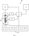
- Fig. 1 illustrates a system to calibrate an ECU of a vehicle, according to an embodiment of the present invention.
- the system 100 enables calibration of the ECU 204 of the vehicle 208 as shown in Fig. 2 .
- the system 100 comprises a remote computer 102, a central server 106, a local computer 110 and a setup 200 comprising at least a dynamometer 210, and at least one actuator 220.
- the setup 200 is also shown in Fig. 2 .
- the dynamometer 210 also referred to as dyno
- the actuator 220 are interfaced and operated with the local computer 110.
- the central server 106 is connected to the local computer 110 by a second networking means 108, and a remote computer 102 is connected to the central server 106 by a first networking means 104.
- the remote computer 102 uploads instructions to the central server 106, executes the instructions through the local computer 110 to operate the dynamometer 210 and the at least one actuator 220, and calibrates the ECU 204 of the vehicle 208.
- the instructions are downloaded to the local computer 110 through the second networking means 108.
- the instructions are provided as scripts (program) for each of the at least one actuator 220.
- the remote computer 102 controls the setup 200 remotely, or the local computer 110 controls the setup 200.
- the first networking means 104 and the second networking means 108 are selected from a group comprising a wired or wireless network such as Local Area Network (LAN), Wireless Local Area Network (WLAN) and the like.
- the setup 200 is allowed to use different communication networks for calibration comprising Controller Area Network (CAN), Universal Asynchronous Receiver/Transmitter (UART), an Inter-Integrated Circuit (I2C), a Serial Peripheral Interface (SPI), a FlexRay and the like.
- CAN Controller Area Network
- UART Universal Asynchronous Receiver/Transmitter
- I2C Inter-Integrated Circuit
- SPI Serial Peripheral Interface
- FlexRay FlexRay and the like.
- the remote computer 102 further displays result of the calibration by accessing the central server 106.
- the result of the calibration are uploaded by the local computer 110 to the central server 106 after end of the calibration.
- the result comprises reports and log files related to the calibration of the ECU 204.
- the system 100 is provided to or accessed by a user as a Subscription as a Service (SaaS). Both the remote computer 102 and the local computer 110 access the central server 106 through a user interface.
- the remote computer 102 is the host and the local computer 110 is the client.
- the remote computer 102 is used by the service provider to upload scripts to the central server 106.
- the local computer 110 is accessed by the client or customer to download the scripts/instructions for performing calibration of the ECU 204.
- Fig. 2 illustrates a setup required for ECU calibration, according to an embodiment of the present invention.
- the setup 200 is provided to automate the calibration of the ECU 204 of the vehicle 208.
- the setup 200 enables automatic control of vehicle and engine operating points by the local computer 110.
- the setup 200 comprises a dynamometer 210 i.e. either an engine dynamometer or a chassis dynamometer.
- the setup 200 further comprises plurality of sensors 222 such as Manifold Air Pressure (MAP) sensor, a Throttle Position Sensor (TPS), a Crank and/or a Cam position and speed sensor, a coolant temperature sensor, an air temperature sensor, an Exhaust Oxygen (Lambda) sensor and the like.
- MAP Manifold Air Pressure
- TPS Throttle Position Sensor
- Crank and/or a Cam position and speed sensor a coolant temperature sensor
- an air temperature sensor an Exhaust Oxygen (Lambda) sensor and the like.
- the setup 200 still further comprises a dyno controller 202 to operate the dynamometer 210, and a communication interface 206 such as a Controller Area Network (CAN) interface to enable communication between the local computer 110 and the dyno controller 202, the ECU 204, the actuator 220, the sensors 222 and the like.
- a communication interface 206 such as a Controller Area Network (CAN) interface to enable communication between the local computer 110 and the dyno controller 202, the ECU 204, the actuator 220, the sensors 222 and the like.
- CAN Controller Area Network
- the actuators 220 is selected from a group comprising a throttle actuator 212, a brake actuator 214, a gear actuator 216, a clutch actuator 218, a fuel injection module (not shown), and a blower (not shown).
- Each actuator 220 comprises a control unit having a microcontroller flashed with actuator program.
- the communication interface 206 to be a CAN transceiver
- the CAN transceiver transmits and receives the CAN message from the CAN bus.
- a stepper motor or other motor or other electro-mechanical assembly is used in the actuator 220.
- a driver circuit for the stepper motor is provided which is controlled by the control unit.
- the remote computer 102 selectively uploads and executes instructions corresponding to said plurality of actuators 220 as selected by the client. Based on the required calibration, the instructions or scripts of the actuator 220 which is required/requested by a client/customer/end user, only those is/are provided for ECU calibration. For example: If calibration is required only with respect to throttle, then scripts, for operating only the throttle actuator 212 is uploaded to the central server 106. Once uploaded, only that specific script is accessible by the client through the local computer 110. Only the subscribed scripts is accessible by the client. Further, the client pays only for the subscription (such as time based, usage based, etc.).
- the communication interface 206 having more than one communication channels are used to reduce the complexity.
- one CAN channel is used to communicate to the vehicle ECU 204.
- the other CAN channel is used to communicate to the actuator 220. So an additional CAN interface between the local computer 110 and actuator 220 is avoided.
- a dedicated database is generated for the actuator 220.
- the instructions are written to control the actuator 220 as the calibration progresses.
- the scripts sends messages with proper message ID to the actuator 220 (according to the database of the actuator 220). Then the actuator 220 is operated and a closed loop control is achieved by checking the actual position/ response by the corresponding sensor 222.
- the dyno controller 202 controls the roller speed of the dynamometer 210 to maintain required vehicle speed/engine speed.
- the blower controller (not shown) controls a cooling fan in the dynamometer 210 to maintain the required engine temperature.
- the at least one actuator 220 is operated automatically by local computer 110 provided with instructions. The instructions coordinates the automated calibration.
- the remote computer 102 is provided or loaded or installed with executable instructions or scripts for each calibration process required for the vehicle 208.
- the instructions are distributed to customers through central server 106.
- the central server 106 such as a cloud based server, is established to distribute the scripts to the customer on subscription basis. The customer is charged based on the subscription.
- the calibration scripts generates reports and log files during the execution. At the end of the calibration activity, the reports and logged data is uploaded back to the central server 106. The reports are used for the analysis and review for diagnostics.
- the delivery of updated calibration scripts to customers are made through the central server 106 as a continuous process.
- the scripts are periodically updated and subscribers or customers are provided with the access as per the subscription.
- the calibration of the ECU 204 is customer guided. Once the calibration scripts are downloaded at the local computer 110, the scripts guides the user/operator to perform or adjust or operate the dynamometer 210 or the at least one actuator 220 to carry out the calibration process. During guided calibration, the system 100 may prompt the user to change the ECU parameter as well.
- Fig. 3 illustrates a flow diagram of a method for calibrating the ECU of the vehicle.
- the vehicle 208 is operated by a dynamometer 210 and at least one actuator 220 through a local computer 110.
- a step 302 comprises connecting the remote computer 102 to the local computer 110 through the central server 106.
- a step 304 comprises uploading instructions to the central server 106 through the remote computer 102.
- a step 306 comprises executing the instructions through the local computer 110 for calibrating the ECU 204.
- the method further comprises uploading result of the calibration to the central server 106 followed by displaying the results in the remote computer 102.
- the method is any one of an automatic process and a guided process by a user/customer intervention.
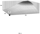
- Fig. 4 illustrates a map used during calibration of air charge distribution, according to an embodiment of the present invention.
- the map 400 is for estimating real mass flow over a throttle valve.
- the map 400 is shown with three axes.
- the X-axis 402 corresponds to throttle position having different set-points.
- the Y-axis 406 represents engine speed.
- the Z-axis 404 represents air charge.
- an electronically controlled throttle actuator 212 is provided to calibrate the map 400.
- the throttle actuator 212 is operated by the local computer 110 on execution of the instructions.
- the throttle actuator 212 is controlled in a manner that the throttle position is set to the first set-point followed by calibration of the point based on engine speed control using the dynamometer 210 and the air charge detection by the MAP sensor.
- the vehicle 208 is brought to each set-point based on a coordinate point on X-axis 402 and Y-axis 406 by controlling the throttle and engine speed by the throttle actuator 212 and the dynamometer 210, respectively.
- the dynamometer 210 is switched to constant velocity mode for calibration and correspondingly the throttle actuator 212 is operated to get the desired throttle position.
- the value of TPS is read from the ECU 204 for a closed loop control of throttle.
- dynamometer 210 is controlled to bring the vehicle 208 to the target engine speed.
- the engine speed is read from ECU 204.
- the engine temperature is monitored. If the engine temperature is out of range, then the blower is switched ON to control the engine temperature. Then the calibration at that point is carried out.
- the next set-point is selected and the suitable actuators 220 are operated to bring the engine/vehicle to that point.
- the process is repeated for all the set-points.
- the calibrated map 400 is again verified with respect to all set-points.
- the throttle actuator 212 is also controllable for transient calibration where the throttle position is shifted between two set-points in a quick manner.
- the automatic or electronic control of the throttle actuator 212 provides an easy and less time consuming system 100. Otherwise, the user needs to set all the set points with manual throttle control followed by verification of the map 400 resulting in decreased accuracy and increased time of calibration.
- a brake actuator 214 is provided.
- the map 400 is adjusted to different points along with application of breaks at different intensity to execute certain test cases.
- the at least one actuator 220 is operated either as a standalone mode or automatic mode. In the standalone mode, the actuator 220, is operated independently providing good accuracy.
- the actuator 220 is controlled by means of a knob or through the local computer 110, or by means of push buttons.
- the actuator 220 is connected to the existing calibration tools.
- the actuator 220 does not require any input from the user.
- the actuator 220 is controlled automatically according to the calibration in progress.
- the communication is through communication interface 206.
- the actuator 220 is allowable to be controlled manually as well, by entering the desired position in the local computer 110. So during calibration and verification, the actuator 220 is controlled automatically and quickly. The required position is maintained with less tolerance.
- Fig. 5 illustrates a use case of the system, according to an embodiment of the present invention.
- the use case depicts a service provider at first location 502 hosting the calibration service through the central server 106.
- a client or customer at a second location 504 access the central server 106, after taking subscription of the calibration service from the service provider.
- the central server 106 comprises plurality of scripts for calibration of different functionalities of the vehicle 208.
- the service provider generates and uploads the calibration scripts 1062, 1064... 1066 to the central server 106.
- Each customer is provided with the subscription to their specific scripts.
- the results 1068 comprising reports and logs uploaded from the customer site at second location 504 is used for review purpose.
- the customer is charged based on the subscription.
- a customer from a third location 506 is also allowed to use the central server 106 for calibration activities.
- a standardized process is provided, which enables easy analysis and troubleshooting. With the availability of the instructions, the customers/ users are able to perform the calibration process without having the expertise.
- the actuator 220 is plug and play type. The development cost and time is significantly reduced.
- the system 100 also gives better reproducibility and performance. Whole calibration activity is automated. Manual intervention is optional and may not be required.
- the setup 200 automates the manual interventions and makes the calibration process efficient.
- the system 100 is also possible to be used for calibration of the ECU 204 within the same premise or building or location, in which case the host and the end user are same.
- the system 100 is applicable for different types of vehicles 208 such as motorcycle, scooter, cars, quads, and the like.
Landscapes
- Engineering & Computer Science (AREA)
- General Engineering & Computer Science (AREA)
- Chemical & Material Sciences (AREA)
- Combustion & Propulsion (AREA)
- Computer Hardware Design (AREA)
- Mechanical Engineering (AREA)
- Physics & Mathematics (AREA)
- General Physics & Mathematics (AREA)
- Microelectronics & Electronic Packaging (AREA)
- Combined Controls Of Internal Combustion Engines (AREA)
- Testing Of Engines (AREA)
- Control Of Vehicle Engines Or Engines For Specific Uses (AREA)
Description
- The present disclosure relates to a system to calibrate an Engine Control Unit (ECU) of a vehicle. More particularly, relates to the system and method to calibrate the ECU remotely through cloud services on subscription basis.
- A delivery of a software/instructions for calibration of a vehicle (such as a series software, a development software) is presently done through E-Mail or through separate server for each customer. When a new software is introduced, the customer has to be trained on the changes and calibration process for the same. Each customer performs calibration in different methods. An expert calibration engineer has to go to customer location often, to do part or complete calibration of different functionalities of the vehicle.
- Engine sound calibration is discussed in
US 2008/0264149 A1 . An engine diagnostic tool is described inUS 2014/0331752 A1 . The calibration of Engine Management System (EMS) or Engine Control Unit (ECU) takes place in the dynamometer. The dynamometer is either an engine dynamometer or a chassis dynamometer. The ECU comprises complex functionalities. There are a lot of MAPs and curves available in the ECU. The MAPs/Curves must be calibrated with accurate values to get the desired performance out of the engine. Presently most of the calibration activities in the chassis dynamometer is done manually. It requires a lot of test iterations which results in increased development time and cost. It requires a lot of effort for verification of calibration and preparation of the report. Most of the process have to be repeated if any improvement is required. - The vehicle operating points has to be changed frequently as the calibration goes on. When the drive cycle measurements are done, a human driver drives the vehicle on the dynamometer. To match the required vehicle driven point, the driver controls the throttle, clutch, gear and break manually. The accuracy of test result depends on the human error. Throttle position, gear, clutch, break, dynamometer rotary speed and dyno blower speed are to be controlled. Manually controlling these parameters requires a lot of attention and time. Most of the time the accuracy and reproducibility are less.
- Hence, there is a need for a system which provides a common platform for calibration services, enabling exchange of automated calibration instructions and results of calibration. Further, there is a need for the system to automate the calibration of the ECU of the vehicle.
- The invention is defined by the system of claim 1 and the method of claim 3.
- An embodiment of the disclosure is described with reference to the following accompanying drawings,
-
Fig. 1 illustrates a system to calibrate an ECU of a vehicle, according to an embodiment of the present invention; -
Fig. 2 illustrates an setup required for ECU calibration, according to an embodiment of the present invention; -
Fig. 3 illustrates a flow diagram of a method for calibrating the ECU of the vehicle; -
Fig. 4 illustrates a map used during calibration of air charge distribution, according to an embodiment of the present invention, and -
Fig. 5 illustrates a use case of the system, according to an embodiment of the present invention. -
Fig. 1 illustrates a system to calibrate an ECU of a vehicle, according to an embodiment of the present invention. Thesystem 100 enables calibration of theECU 204 of thevehicle 208 as shown inFig. 2 . Thesystem 100 comprises aremote computer 102, acentral server 106, alocal computer 110 and asetup 200 comprising at least adynamometer 210, and at least oneactuator 220. Thesetup 200 is also shown inFig. 2 . The dynamometer 210 (also referred to as dyno) and theactuator 220 are interfaced and operated with thelocal computer 110. Thecentral server 106 is connected to thelocal computer 110 by a second networking means 108, and aremote computer 102 is connected to thecentral server 106 by a first networking means 104. Theremote computer 102, uploads instructions to thecentral server 106, executes the instructions through thelocal computer 110 to operate thedynamometer 210 and the at least oneactuator 220, and calibrates theECU 204 of thevehicle 208. The instructions are downloaded to thelocal computer 110 through the second networking means 108. The instructions are provided as scripts (program) for each of the at least oneactuator 220. - The
remote computer 102 controls thesetup 200 remotely, or thelocal computer 110 controls thesetup 200. The first networking means 104 and the second networking means 108 are selected from a group comprising a wired or wireless network such as Local Area Network (LAN), Wireless Local Area Network (WLAN) and the like. Further, thesetup 200 is allowed to use different communication networks for calibration comprising Controller Area Network (CAN), Universal Asynchronous Receiver/Transmitter (UART), an Inter-Integrated Circuit (I2C), a Serial Peripheral Interface (SPI), a FlexRay and the like. - The
remote computer 102 further displays result of the calibration by accessing thecentral server 106. The result of the calibration are uploaded by thelocal computer 110 to thecentral server 106 after end of the calibration. The result comprises reports and log files related to the calibration of theECU 204. - The
system 100 is provided to or accessed by a user as a Subscription as a Service (SaaS). Both theremote computer 102 and thelocal computer 110 access thecentral server 106 through a user interface. Theremote computer 102 is the host and thelocal computer 110 is the client. In accordance to an embodiment of the present invention, theremote computer 102 is used by the service provider to upload scripts to thecentral server 106. Thelocal computer 110 is accessed by the client or customer to download the scripts/instructions for performing calibration of theECU 204. -
Fig. 2 illustrates a setup required for ECU calibration, according to an embodiment of the present invention. Thesetup 200 is provided to automate the calibration of theECU 204 of thevehicle 208. Thesetup 200 enables automatic control of vehicle and engine operating points by thelocal computer 110. Thesetup 200 comprises adynamometer 210 i.e. either an engine dynamometer or a chassis dynamometer. Thesetup 200 further comprises plurality ofsensors 222 such as Manifold Air Pressure (MAP) sensor, a Throttle Position Sensor (TPS), a Crank and/or a Cam position and speed sensor, a coolant temperature sensor, an air temperature sensor, an Exhaust Oxygen (Lambda) sensor and the like. Thesetup 200 still further comprises adyno controller 202 to operate thedynamometer 210, and acommunication interface 206 such as a Controller Area Network (CAN) interface to enable communication between thelocal computer 110 and thedyno controller 202, theECU 204, theactuator 220, thesensors 222 and the like. - According to the claimed invention, the
actuators 220 is selected from a group comprising athrottle actuator 212, abrake actuator 214, agear actuator 216, aclutch actuator 218, a fuel injection module (not shown), and a blower (not shown). Eachactuator 220 comprises a control unit having a microcontroller flashed with actuator program. Considering thecommunication interface 206 to be a CAN transceiver, the CAN transceiver transmits and receives the CAN message from the CAN bus. A stepper motor or other motor or other electro-mechanical assembly is used in theactuator 220. A driver circuit for the stepper motor is provided which is controlled by the control unit. - According to the claimed invention, the
remote computer 102 selectively uploads and executes instructions corresponding to said plurality ofactuators 220 as selected by the client. Based on the required calibration, the instructions or scripts of theactuator 220 which is required/requested by a client/customer/end user, only those is/are provided for ECU calibration. For example: If calibration is required only with respect to throttle, then scripts, for operating only thethrottle actuator 212 is uploaded to thecentral server 106. Once uploaded, only that specific script is accessible by the client through thelocal computer 110. Only the subscribed scripts is accessible by the client. Further, the client pays only for the subscription (such as time based, usage based, etc.). - For calibration and measurement activities, the
communication interface 206 having more than one communication channels are used to reduce the complexity. Such as in the CAN transceiver, one CAN channel is used to communicate to thevehicle ECU 204. The other CAN channel is used to communicate to theactuator 220. So an additional CAN interface between thelocal computer 110 andactuator 220 is avoided. Further, a dedicated database is generated for theactuator 220. The instructions are written to control theactuator 220 as the calibration progresses. The scripts sends messages with proper message ID to the actuator 220 (according to the database of the actuator 220). Then theactuator 220 is operated and a closed loop control is achieved by checking the actual position/ response by the correspondingsensor 222. - The
dyno controller 202 controls the roller speed of thedynamometer 210 to maintain required vehicle speed/engine speed. The blower controller (not shown) controls a cooling fan in thedynamometer 210 to maintain the required engine temperature. At every point of the calibration of theECU 204, the at least oneactuator 220 is operated automatically bylocal computer 110 provided with instructions. The instructions coordinates the automated calibration. - The
remote computer 102 is provided or loaded or installed with executable instructions or scripts for each calibration process required for thevehicle 208. The instructions are distributed to customers throughcentral server 106. To enable calibration, thestandardized setup 200 is formed. Thecentral server 106 such as a cloud based server, is established to distribute the scripts to the customer on subscription basis. The customer is charged based on the subscription. The calibration scripts generates reports and log files during the execution. At the end of the calibration activity, the reports and logged data is uploaded back to thecentral server 106. The reports are used for the analysis and review for diagnostics. The delivery of updated calibration scripts to customers are made through thecentral server 106 as a continuous process. The scripts are periodically updated and subscribers or customers are provided with the access as per the subscription. - In another embodiment of the present invention, the calibration of the
ECU 204 is customer guided. Once the calibration scripts are downloaded at thelocal computer 110, the scripts guides the user/operator to perform or adjust or operate thedynamometer 210 or the at least oneactuator 220 to carry out the calibration process. During guided calibration, thesystem 100 may prompt the user to change the ECU parameter as well. -
Fig. 3 illustrates a flow diagram of a method for calibrating the ECU of the vehicle. Thevehicle 208 is operated by adynamometer 210 and at least oneactuator 220 through alocal computer 110. Astep 302 comprises connecting theremote computer 102 to thelocal computer 110 through thecentral server 106. Astep 304 comprises uploading instructions to thecentral server 106 through theremote computer 102. Astep 306 comprises executing the instructions through thelocal computer 110 for calibrating theECU 204. - The method further comprises uploading result of the calibration to the
central server 106 followed by displaying the results in theremote computer 102. The method is any one of an automatic process and a guided process by a user/customer intervention. -
Fig. 4 illustrates a map used during calibration of air charge distribution, according to an embodiment of the present invention. Themap 400 is for estimating real mass flow over a throttle valve. Themap 400 is shown with three axes. TheX-axis 402 corresponds to throttle position having different set-points. The Y-axis 406 represents engine speed. The Z-axis 404 represents air charge. In accordance to an embodiment of the present invention, to calibrate themap 400, an electronically controlledthrottle actuator 212 is provided. Thethrottle actuator 212 is operated by thelocal computer 110 on execution of the instructions. Thethrottle actuator 212 is controlled in a manner that the throttle position is set to the first set-point followed by calibration of the point based on engine speed control using thedynamometer 210 and the air charge detection by the MAP sensor. - To calibrate the
map 400, thevehicle 208 is brought to each set-point based on a coordinate point onX-axis 402 and Y-axis 406 by controlling the throttle and engine speed by thethrottle actuator 212 and thedynamometer 210, respectively. Thedynamometer 210 is switched to constant velocity mode for calibration and correspondingly thethrottle actuator 212 is operated to get the desired throttle position. The value of TPS is read from theECU 204 for a closed loop control of throttle. Thendynamometer 210 is controlled to bring thevehicle 208 to the target engine speed. The engine speed is read fromECU 204. Simultaneously, the engine temperature is monitored. If the engine temperature is out of range, then the blower is switched ON to control the engine temperature. Then the calibration at that point is carried out. After the calibration of first set-point, the next set-point is selected and thesuitable actuators 220 are operated to bring the engine/vehicle to that point. - The process is repeated for all the set-points. After the calibration of the
map 400, the calibratedmap 400 is again verified with respect to all set-points. Thethrottle actuator 212 is also controllable for transient calibration where the throttle position is shifted between two set-points in a quick manner. The automatic or electronic control of thethrottle actuator 212 provides an easy and lesstime consuming system 100. Otherwise, the user needs to set all the set points with manual throttle control followed by verification of themap 400 resulting in decreased accuracy and increased time of calibration. - In accordance to an embodiment of the present invention, a
brake actuator 214 is provided. Themap 400 is adjusted to different points along with application of breaks at different intensity to execute certain test cases. - In accordance to an embodiment of the present invention, the at least one
actuator 220 is operated either as a standalone mode or automatic mode. In the standalone mode, theactuator 220, is operated independently providing good accuracy. Theactuator 220 is controlled by means of a knob or through thelocal computer 110, or by means of push buttons. - In automatic mode, the
actuator 220 is connected to the existing calibration tools. Theactuator 220 does not require any input from the user. Theactuator 220 is controlled automatically according to the calibration in progress. The communication is throughcommunication interface 206. Theactuator 220 is allowable to be controlled manually as well, by entering the desired position in thelocal computer 110. So during calibration and verification, theactuator 220 is controlled automatically and quickly. The required position is maintained with less tolerance. -
Fig. 5 illustrates a use case of the system, according to an embodiment of the present invention. The use case depicts a service provider atfirst location 502 hosting the calibration service through thecentral server 106. A client or customer at asecond location 504 access thecentral server 106, after taking subscription of the calibration service from the service provider. Thecentral server 106 comprises plurality of scripts for calibration of different functionalities of thevehicle 208. Here the service provider generates and uploads thecalibration scripts 1062, 1064... 1066 to thecentral server 106. Each customer is provided with the subscription to their specific scripts. Theresults 1068 comprising reports and logs uploaded from the customer site atsecond location 504 is used for review purpose. The customer is charged based on the subscription. Similarly, a customer from athird location 506 is also allowed to use thecentral server 106 for calibration activities. - In accordance to an embodiment of the present invention, a standardized process is provided, which enables easy analysis and troubleshooting. With the availability of the instructions, the customers/ users are able to perform the calibration process without having the expertise. The
actuator 220 is plug and play type. The development cost and time is significantly reduced. Thesystem 100 also gives better reproducibility and performance. Whole calibration activity is automated. Manual intervention is optional and may not be required. Thesetup 200 automates the manual interventions and makes the calibration process efficient. Thesystem 100 is also possible to be used for calibration of theECU 204 within the same premise or building or location, in which case the host and the end user are same. Thesystem 100 is applicable for different types ofvehicles 208 such as motorcycle, scooter, cars, quads, and the like. - It should be understood that embodiments explained in the description above are only illustrative and do not limit the scope of this invention. Many such embodiments and other modifications and changes in the embodiment explained in the description are envisaged. The scope of the invention is only limited by the scope of the appended claims.
Claims (5)
- A system (100) to calibrate an Engine Control Unit, ECU, (204) of a vehicle (208), said system (100) comprising:at least a dynamometer (210);a plurality of actuators (220) interfaced and operated with a local computer (110), wherein said plurality of actuators (220) is selected from a group comprising a throttle actuator (212), a brake actuator (214), a gear actuator (216), a clutch actuator (218), a fuel injection module and a blower; characterized in that the system (100) further comprisesa remote computer (102) connected to said local computer (110) through a central server (106) by a first networking means (104) and a second networking means (108), wherein said remote computer (102) is adapted to- upload instructions to said central server (106),- execute said instructions through said local computer (110) to operate said dynamometer (210) and said plurality of actuators (220), and- calibrate said ECU (204);wherein said remote computer (102) is adapted to selectively upload and execute instructions corresponding to said plurality of actuators (220) based on a selection by a client on the local computer (100),wherein, based on a required calibration, only instructions or scripts of the actuator (220) required by the client are provided for ECU calibration.
- The system (100) as claimed in claim 1, wherein said remote computer (102) further displays a result uploaded in said central server (106), said result is uploaded by said local computer (110) after end of said calibration.
- A method for calibrating an Engine Control Unit, ECU, (204) of a vehicle (208), wherein said vehicle (208) is operated by a dynamometer and a plurality of actuators (220) through a local computer (110), wherein said plurality of actuators (220) is selected from a group comprising a throttle actuator (212), a brake actuator (214), a gear actuator (216), a clutch actuator (218) and a fuel injection module, characterized in that said method
comprising the steps of:connecting a remote computer (102) to said local computer (110) through a central server (106);uploading instructions to said central server (106) through said remote computer (102), andexecuting said instructions through said local computer (110) for calibrating said ECU (204),wherein said remote computer (102) selectively uploads and executes instructions corresponding to said plurality of actuators (220) based on a selection by a client on the local computer, wherein, based on a required calibration, only instructions or scripts of the actuator (220) required by the client are provided for ECU calibration. - The method as claimed in claim 3, further comprising uploading a result of said calibration to said central server (106) followed by displaying said result in said remote computer (102).
- The method as claimed in claim 3, being executed by any one of an automatic process, and a guided process through a user intervention.
Applications Claiming Priority (2)
| Application Number | Priority Date | Filing Date | Title |
|---|---|---|---|
| IN201641043689 | 2016-12-21 | ||
| PCT/EP2017/081647 WO2018114329A1 (en) | 2016-12-21 | 2017-12-06 | A system and method to calibrate an engine control unit (ecu) of a vehicle |
Publications (2)
| Publication Number | Publication Date |
|---|---|
| EP3565963A1 EP3565963A1 (en) | 2019-11-13 |
| EP3565963B1 true EP3565963B1 (en) | 2023-06-07 |
Family
ID=60813816
Family Applications (1)
| Application Number | Title | Priority Date | Filing Date |
|---|---|---|---|
| EP17821821.0A Active EP3565963B1 (en) | 2016-12-21 | 2017-12-06 | A system and method to calibrate an engine control unit (ecu) of a vehicle |
Country Status (5)
| Country | Link |
|---|---|
| US (1) | US11572846B2 (en) |
| EP (1) | EP3565963B1 (en) |
| JP (1) | JP6824418B2 (en) |
| KR (1) | KR20190092555A (en) |
| WO (1) | WO2018114329A1 (en) |
Families Citing this family (7)
| Publication number | Priority date | Publication date | Assignee | Title |
|---|---|---|---|---|
| KR102187104B1 (en) * | 2019-10-08 | 2020-12-04 | 주식회사 현대케피코 | Fuel calibration method and system |
| KR102899319B1 (en) * | 2020-06-08 | 2025-12-15 | 주식회사 에이치엘클레무브 | Apparatus and method for inspecting process and, electronic control apparatus |
| CN115437911A (en) * | 2021-09-23 | 2022-12-06 | 北京车和家信息技术有限公司 | Vehicle calibration detection method and device, vehicle, calibration equipment and storage medium |
| WO2023072697A1 (en) * | 2021-10-27 | 2023-05-04 | Robert Bosch Gmbh | A system and method for automated calibration of an engine parameter in a vehicle |
| US12140101B2 (en) * | 2022-01-18 | 2024-11-12 | Briggs & Stratton, Llc | Engine calibration systems and methods |
| US12554483B2 (en) | 2023-09-08 | 2026-02-17 | Shanghai Tosun Technology Ltd. | Vehicular multi-location synergic remote calibration system and a calibration method thereof |
| CN120017676B (en) * | 2025-03-12 | 2025-10-17 | 重庆赛力斯凤凰智创科技有限公司 | A remote calibration system, method, device and medium |
Family Cites Families (14)
| Publication number | Priority date | Publication date | Assignee | Title |
|---|---|---|---|---|
| DE69213809T2 (en) * | 1991-03-29 | 1997-02-20 | Cummins Engine Co Inc | Method and device for generating calibration information for an electronic engine control module |
| DE69739487D1 (en) * | 1996-11-13 | 2009-08-20 | Toyota Motor Co Ltd | COMMUNICATION DEVICE OF INFORMATION ON MOTOR VEHICLES AND COMMUNICATION SYSTEM OF INFORMATION ON MOTOR VEHICLES |
| US20020018982A1 (en) * | 2000-05-12 | 2002-02-14 | Conroy Steven J. | Dynamometer racing simulator |
| US7047125B1 (en) * | 2005-02-25 | 2006-05-16 | Caterpillar Inc. | Internal combustion engine performance calibration systems |
| US7484405B2 (en) | 2007-04-26 | 2009-02-03 | Gm Global Technology Operations, Inc. | System and method for engine sound calibration |
| JP2010084631A (en) * | 2008-09-30 | 2010-04-15 | Keihin Corp | Engine setting system and engine setting method |
| JP5846042B2 (en) | 2012-05-16 | 2016-01-20 | 株式会社デンソー | Remote engine starter and in-vehicle device |
| US9708960B2 (en) | 2013-05-08 | 2017-07-18 | Cummins Ip, Inc. | Exhaust aftertreatment system diagnostic and conditioning |
| WO2014193347A1 (en) * | 2013-05-29 | 2014-12-04 | International Engine Intellectual Property Company, Llc | Automated assembly of ecu calibrations |
| US9158926B2 (en) * | 2014-01-13 | 2015-10-13 | General Electric Company | Engine control unit configuration security |
| CN204439365U (en) | 2015-02-25 | 2015-07-01 | 霸州市华威发动机技术有限公司 | A kind of engine operating parameter calibration facility based on wireless telecommunications |
| US9726280B2 (en) * | 2015-03-25 | 2017-08-08 | Ford Global Technologies, Llc | Transmission calibration tool |
| JP6618447B2 (en) * | 2015-12-10 | 2019-12-11 | 株式会社堀場製作所 | Vehicle speed pattern display device, program used in this device, running test method, and automatic driving device |
| EP3652721A1 (en) * | 2017-09-04 | 2020-05-20 | NNG Software Developing and Commercial LLC | A method and apparatus for collecting and using sensor data from a vehicle |
-
2017
- 2017-12-06 JP JP2019534830A patent/JP6824418B2/en not_active Expired - Fee Related
- 2017-12-06 EP EP17821821.0A patent/EP3565963B1/en active Active
- 2017-12-06 KR KR1020197020509A patent/KR20190092555A/en not_active Ceased
- 2017-12-06 US US16/467,117 patent/US11572846B2/en active Active
- 2017-12-06 WO PCT/EP2017/081647 patent/WO2018114329A1/en not_active Ceased
Also Published As
| Publication number | Publication date |
|---|---|
| US11572846B2 (en) | 2023-02-07 |
| JP2020504796A (en) | 2020-02-13 |
| WO2018114329A1 (en) | 2018-06-28 |
| JP6824418B2 (en) | 2021-02-03 |
| US20190316539A1 (en) | 2019-10-17 |
| KR20190092555A (en) | 2019-08-07 |
| EP3565963A1 (en) | 2019-11-13 |
Similar Documents
| Publication | Publication Date | Title |
|---|---|---|
| EP3565963B1 (en) | A system and method to calibrate an engine control unit (ecu) of a vehicle | |
| CN105092260B (en) | Vehicle test system, vehicle component test device and vehicle test method | |
| US9009013B2 (en) | Method and device for verification of an automation system | |
| US20150094929A1 (en) | Vehicle diagnostic and prognostic systems and methods | |
| US8688313B2 (en) | Remote vehicle programming system and method | |
| US20150094903A1 (en) | Vehicle diagnostic and prognostic systems and methods | |
| US10546073B2 (en) | Communication simulating system, communication simulating method, and vehicle communication apparatus | |
| CN104007752A (en) | Method for generating a configuration for a control unit test system | |
| CN104968539B (en) | Method and mechanism for running the first motor vehicle on the basis of at least one characteristic parameter of at least one the second motor vehicle | |
| CN110609492A (en) | Semi-physical simulation test system and method for key components of hybrid power assembly | |
| US20160171791A1 (en) | Method and Apparatus For Remote Diagnostics and Maintenance of Vehicles | |
| US11561873B2 (en) | Test equipment interface add-on having a production support equipment module and a selectively removable test support equipment module | |
| CN117970898A (en) | Commercial vehicle whole vehicle EOL offline detection method | |
| CN106462155B (en) | Diagnose the method for automotive system, the diagnostic device of automotive system, the control equipment of automotive system and motor vehicle | |
| JP2008224290A (en) | Vehicle running virtual test system, method and program | |
| EP1687950A1 (en) | Arrangement for distributed measurement system for measurement and simulation in distributed control systems, for example in vehicles | |
| US20080161994A1 (en) | Method and system for autogenerating static fault code data based on a unified summary table for heavy duty diesel engines | |
| US20090326904A1 (en) | Apparatus and method for virtual assembly, integration and testing of an integrated system | |
| CN119310970A (en) | Engine virtual bench calibration test system and method | |
| KR102279671B1 (en) | Exhaust gas certification test system and method | |
| CN117914760A (en) | Cloud test method, device, equipment and medium of vehicle-mounted terminal | |
| US11386725B2 (en) | Vehicle diagnostic apparatus | |
| Alvear et al. | VEWE: A vehicle ECU wireless emulation tool supporting OBD-II communication and geopositioning | |
| Linssen et al. | Simulation of Networked ECUs for Drivability Calibration | |
| KR102187104B1 (en) | Fuel calibration method and system |
Legal Events
| Date | Code | Title | Description |
|---|---|---|---|
| STAA | Information on the status of an ep patent application or granted ep patent |
Free format text: STATUS: UNKNOWN |
|
| STAA | Information on the status of an ep patent application or granted ep patent |
Free format text: STATUS: THE INTERNATIONAL PUBLICATION HAS BEEN MADE |
|
| PUAI | Public reference made under article 153(3) epc to a published international application that has entered the european phase |
Free format text: ORIGINAL CODE: 0009012 |
|
| STAA | Information on the status of an ep patent application or granted ep patent |
Free format text: STATUS: REQUEST FOR EXAMINATION WAS MADE |
|
| 17P | Request for examination filed |
Effective date: 20190722 |
|
| AK | Designated contracting states |
Kind code of ref document: A1 Designated state(s): AL AT BE BG CH CY CZ DE DK EE ES FI FR GB GR HR HU IE IS IT LI LT LU LV MC MK MT NL NO PL PT RO RS SE SI SK SM TR |
|
| AX | Request for extension of the european patent |
Extension state: BA ME |
|
| DAV | Request for validation of the european patent (deleted) | ||
| DAX | Request for extension of the european patent (deleted) | ||
| RAP1 | Party data changed (applicant data changed or rights of an application transferred) |
Owner name: ROBERT BOSCH GMBH Owner name: BOSCH LIMITED |
|
| STAA | Information on the status of an ep patent application or granted ep patent |
Free format text: STATUS: EXAMINATION IS IN PROGRESS |
|
| 17Q | First examination report despatched |
Effective date: 20210114 |
|
| INTG | Intention to grant announced |
Effective date: 20221130 |
|
| STAA | Information on the status of an ep patent application or granted ep patent |
Free format text: STATUS: GRANT OF PATENT IS INTENDED |
|
| GRAS | Grant fee paid |
Free format text: ORIGINAL CODE: EPIDOSNIGR3 |
|
| GRAA | (expected) grant |
Free format text: ORIGINAL CODE: 0009210 |
|
| STAA | Information on the status of an ep patent application or granted ep patent |
Free format text: STATUS: THE PATENT HAS BEEN GRANTED |
|
| AK | Designated contracting states |
Kind code of ref document: B1 Designated state(s): AL AT BE BG CH CY CZ DE DK EE ES FI FR GB GR HR HU IE IS IT LI LT LU LV MC MK MT NL NO PL PT RO RS SE SI SK SM TR |
|
| REG | Reference to a national code |
Ref country code: GB Ref legal event code: FG4D |
|
| REG | Reference to a national code |
Ref country code: CH Ref legal event code: EP Ref country code: AT Ref legal event code: REF Ref document number: 1575748 Country of ref document: AT Kind code of ref document: T Effective date: 20230615 |
|
| REG | Reference to a national code |
Ref country code: DE Ref legal event code: R096 Ref document number: 602017069834 Country of ref document: DE |
|
| REG | Reference to a national code |
Ref country code: LT Ref legal event code: MG9D |
|
| REG | Reference to a national code |
Ref country code: NL Ref legal event code: MP Effective date: 20230607 |
|
| PG25 | Lapsed in a contracting state [announced via postgrant information from national office to epo] |
Ref country code: SE Free format text: LAPSE BECAUSE OF FAILURE TO SUBMIT A TRANSLATION OF THE DESCRIPTION OR TO PAY THE FEE WITHIN THE PRESCRIBED TIME-LIMIT Effective date: 20230607 Ref country code: NO Free format text: LAPSE BECAUSE OF FAILURE TO SUBMIT A TRANSLATION OF THE DESCRIPTION OR TO PAY THE FEE WITHIN THE PRESCRIBED TIME-LIMIT Effective date: 20230907 Ref country code: ES Free format text: LAPSE BECAUSE OF FAILURE TO SUBMIT A TRANSLATION OF THE DESCRIPTION OR TO PAY THE FEE WITHIN THE PRESCRIBED TIME-LIMIT Effective date: 20230607 |
|
| PG25 | Lapsed in a contracting state [announced via postgrant information from national office to epo] |
Ref country code: RS Free format text: LAPSE BECAUSE OF FAILURE TO SUBMIT A TRANSLATION OF THE DESCRIPTION OR TO PAY THE FEE WITHIN THE PRESCRIBED TIME-LIMIT Effective date: 20230607 Ref country code: NL Free format text: LAPSE BECAUSE OF FAILURE TO SUBMIT A TRANSLATION OF THE DESCRIPTION OR TO PAY THE FEE WITHIN THE PRESCRIBED TIME-LIMIT Effective date: 20230607 Ref country code: LV Free format text: LAPSE BECAUSE OF FAILURE TO SUBMIT A TRANSLATION OF THE DESCRIPTION OR TO PAY THE FEE WITHIN THE PRESCRIBED TIME-LIMIT Effective date: 20230607 Ref country code: LT Free format text: LAPSE BECAUSE OF FAILURE TO SUBMIT A TRANSLATION OF THE DESCRIPTION OR TO PAY THE FEE WITHIN THE PRESCRIBED TIME-LIMIT Effective date: 20230607 Ref country code: HR Free format text: LAPSE BECAUSE OF FAILURE TO SUBMIT A TRANSLATION OF THE DESCRIPTION OR TO PAY THE FEE WITHIN THE PRESCRIBED TIME-LIMIT Effective date: 20230607 Ref country code: GR Free format text: LAPSE BECAUSE OF FAILURE TO SUBMIT A TRANSLATION OF THE DESCRIPTION OR TO PAY THE FEE WITHIN THE PRESCRIBED TIME-LIMIT Effective date: 20230908 |
|
| PG25 | Lapsed in a contracting state [announced via postgrant information from national office to epo] |
Ref country code: FI Free format text: LAPSE BECAUSE OF FAILURE TO SUBMIT A TRANSLATION OF THE DESCRIPTION OR TO PAY THE FEE WITHIN THE PRESCRIBED TIME-LIMIT Effective date: 20230607 |
|
| REG | Reference to a national code |
Ref country code: AT Ref legal event code: UEP Ref document number: 1575748 Country of ref document: AT Kind code of ref document: T Effective date: 20230607 |
|
| PG25 | Lapsed in a contracting state [announced via postgrant information from national office to epo] |
Ref country code: SK Free format text: LAPSE BECAUSE OF FAILURE TO SUBMIT A TRANSLATION OF THE DESCRIPTION OR TO PAY THE FEE WITHIN THE PRESCRIBED TIME-LIMIT Effective date: 20230607 |
|
| PG25 | Lapsed in a contracting state [announced via postgrant information from national office to epo] |
Ref country code: IS Free format text: LAPSE BECAUSE OF FAILURE TO SUBMIT A TRANSLATION OF THE DESCRIPTION OR TO PAY THE FEE WITHIN THE PRESCRIBED TIME-LIMIT Effective date: 20231007 |
|
| PG25 | Lapsed in a contracting state [announced via postgrant information from national office to epo] |
Ref country code: SM Free format text: LAPSE BECAUSE OF FAILURE TO SUBMIT A TRANSLATION OF THE DESCRIPTION OR TO PAY THE FEE WITHIN THE PRESCRIBED TIME-LIMIT Effective date: 20230607 Ref country code: SK Free format text: LAPSE BECAUSE OF FAILURE TO SUBMIT A TRANSLATION OF THE DESCRIPTION OR TO PAY THE FEE WITHIN THE PRESCRIBED TIME-LIMIT Effective date: 20230607 Ref country code: RO Free format text: LAPSE BECAUSE OF FAILURE TO SUBMIT A TRANSLATION OF THE DESCRIPTION OR TO PAY THE FEE WITHIN THE PRESCRIBED TIME-LIMIT Effective date: 20230607 Ref country code: PT Free format text: LAPSE BECAUSE OF FAILURE TO SUBMIT A TRANSLATION OF THE DESCRIPTION OR TO PAY THE FEE WITHIN THE PRESCRIBED TIME-LIMIT Effective date: 20231009 Ref country code: IS Free format text: LAPSE BECAUSE OF FAILURE TO SUBMIT A TRANSLATION OF THE DESCRIPTION OR TO PAY THE FEE WITHIN THE PRESCRIBED TIME-LIMIT Effective date: 20231007 Ref country code: EE Free format text: LAPSE BECAUSE OF FAILURE TO SUBMIT A TRANSLATION OF THE DESCRIPTION OR TO PAY THE FEE WITHIN THE PRESCRIBED TIME-LIMIT Effective date: 20230607 Ref country code: CZ Free format text: LAPSE BECAUSE OF FAILURE TO SUBMIT A TRANSLATION OF THE DESCRIPTION OR TO PAY THE FEE WITHIN THE PRESCRIBED TIME-LIMIT Effective date: 20230607 |
|
| PGFP | Annual fee paid to national office [announced via postgrant information from national office to epo] |
Ref country code: AT Payment date: 20231214 Year of fee payment: 7 |
|
| PG25 | Lapsed in a contracting state [announced via postgrant information from national office to epo] |
Ref country code: PL Free format text: LAPSE BECAUSE OF FAILURE TO SUBMIT A TRANSLATION OF THE DESCRIPTION OR TO PAY THE FEE WITHIN THE PRESCRIBED TIME-LIMIT Effective date: 20230607 |
|
| REG | Reference to a national code |
Ref country code: DE Ref legal event code: R097 Ref document number: 602017069834 Country of ref document: DE |
|
| PLBE | No opposition filed within time limit |
Free format text: ORIGINAL CODE: 0009261 |
|
| STAA | Information on the status of an ep patent application or granted ep patent |
Free format text: STATUS: NO OPPOSITION FILED WITHIN TIME LIMIT |
|
| PG25 | Lapsed in a contracting state [announced via postgrant information from national office to epo] |
Ref country code: DK Free format text: LAPSE BECAUSE OF FAILURE TO SUBMIT A TRANSLATION OF THE DESCRIPTION OR TO PAY THE FEE WITHIN THE PRESCRIBED TIME-LIMIT Effective date: 20230607 |
|
| PGFP | Annual fee paid to national office [announced via postgrant information from national office to epo] |
Ref country code: DE Payment date: 20240227 Year of fee payment: 7 |
|
| PG25 | Lapsed in a contracting state [announced via postgrant information from national office to epo] |
Ref country code: SI Free format text: LAPSE BECAUSE OF FAILURE TO SUBMIT A TRANSLATION OF THE DESCRIPTION OR TO PAY THE FEE WITHIN THE PRESCRIBED TIME-LIMIT Effective date: 20230607 |
|
| 26N | No opposition filed |
Effective date: 20240308 |
|
| PG25 | Lapsed in a contracting state [announced via postgrant information from national office to epo] |
Ref country code: SI Free format text: LAPSE BECAUSE OF FAILURE TO SUBMIT A TRANSLATION OF THE DESCRIPTION OR TO PAY THE FEE WITHIN THE PRESCRIBED TIME-LIMIT Effective date: 20230607 |
|
| PGFP | Annual fee paid to national office [announced via postgrant information from national office to epo] |
Ref country code: IT Payment date: 20231229 Year of fee payment: 7 |
|
| REG | Reference to a national code |
Ref country code: CH Ref legal event code: PL |
|
| PG25 | Lapsed in a contracting state [announced via postgrant information from national office to epo] |
Ref country code: LU Free format text: LAPSE BECAUSE OF NON-PAYMENT OF DUE FEES Effective date: 20231206 |
|
| PG25 | Lapsed in a contracting state [announced via postgrant information from national office to epo] |
Ref country code: MC Free format text: LAPSE BECAUSE OF FAILURE TO SUBMIT A TRANSLATION OF THE DESCRIPTION OR TO PAY THE FEE WITHIN THE PRESCRIBED TIME-LIMIT Effective date: 20230607 |
|
| GBPC | Gb: european patent ceased through non-payment of renewal fee |
Effective date: 20231206 |
|
| REG | Reference to a national code |
Ref country code: BE Ref legal event code: MM Effective date: 20231231 |
|
| PG25 | Lapsed in a contracting state [announced via postgrant information from national office to epo] |
Ref country code: MC Free format text: LAPSE BECAUSE OF FAILURE TO SUBMIT A TRANSLATION OF THE DESCRIPTION OR TO PAY THE FEE WITHIN THE PRESCRIBED TIME-LIMIT Effective date: 20230607 Ref country code: LU Free format text: LAPSE BECAUSE OF NON-PAYMENT OF DUE FEES Effective date: 20231206 |
|
| REG | Reference to a national code |
Ref country code: IE Ref legal event code: MM4A |
|
| PG25 | Lapsed in a contracting state [announced via postgrant information from national office to epo] |
Ref country code: IE Free format text: LAPSE BECAUSE OF NON-PAYMENT OF DUE FEES Effective date: 20231206 |
|
| PG25 | Lapsed in a contracting state [announced via postgrant information from national office to epo] |
Ref country code: GB Free format text: LAPSE BECAUSE OF NON-PAYMENT OF DUE FEES Effective date: 20231206 |
|
| PG25 | Lapsed in a contracting state [announced via postgrant information from national office to epo] |
Ref country code: BE Free format text: LAPSE BECAUSE OF NON-PAYMENT OF DUE FEES Effective date: 20231231 |
|
| PG25 | Lapsed in a contracting state [announced via postgrant information from national office to epo] |
Ref country code: FR Free format text: LAPSE BECAUSE OF NON-PAYMENT OF DUE FEES Effective date: 20231231 |
|
| PG25 | Lapsed in a contracting state [announced via postgrant information from national office to epo] |
Ref country code: CH Free format text: LAPSE BECAUSE OF NON-PAYMENT OF DUE FEES Effective date: 20231231 |
|
| PG25 | Lapsed in a contracting state [announced via postgrant information from national office to epo] |
Ref country code: IE Free format text: LAPSE BECAUSE OF NON-PAYMENT OF DUE FEES Effective date: 20231206 Ref country code: GB Free format text: LAPSE BECAUSE OF NON-PAYMENT OF DUE FEES Effective date: 20231206 Ref country code: FR Free format text: LAPSE BECAUSE OF NON-PAYMENT OF DUE FEES Effective date: 20231231 Ref country code: CH Free format text: LAPSE BECAUSE OF NON-PAYMENT OF DUE FEES Effective date: 20231231 Ref country code: BE Free format text: LAPSE BECAUSE OF NON-PAYMENT OF DUE FEES Effective date: 20231231 |
|
| PG25 | Lapsed in a contracting state [announced via postgrant information from national office to epo] |
Ref country code: BG Free format text: LAPSE BECAUSE OF FAILURE TO SUBMIT A TRANSLATION OF THE DESCRIPTION OR TO PAY THE FEE WITHIN THE PRESCRIBED TIME-LIMIT Effective date: 20230607 |
|
| PG25 | Lapsed in a contracting state [announced via postgrant information from national office to epo] |
Ref country code: BG Free format text: LAPSE BECAUSE OF FAILURE TO SUBMIT A TRANSLATION OF THE DESCRIPTION OR TO PAY THE FEE WITHIN THE PRESCRIBED TIME-LIMIT Effective date: 20230607 |
|
| REG | Reference to a national code |
Ref country code: DE Ref legal event code: R119 Ref document number: 602017069834 Country of ref document: DE |
|
| PG25 | Lapsed in a contracting state [announced via postgrant information from national office to epo] |
Ref country code: CY Free format text: LAPSE BECAUSE OF FAILURE TO SUBMIT A TRANSLATION OF THE DESCRIPTION OR TO PAY THE FEE WITHIN THE PRESCRIBED TIME-LIMIT; INVALID AB INITIO Effective date: 20171206 |
|
| REG | Reference to a national code |
Ref country code: AT Ref legal event code: MM01 Ref document number: 1575748 Country of ref document: AT Kind code of ref document: T Effective date: 20241206 |
|
| PG25 | Lapsed in a contracting state [announced via postgrant information from national office to epo] |
Ref country code: HU Free format text: LAPSE BECAUSE OF FAILURE TO SUBMIT A TRANSLATION OF THE DESCRIPTION OR TO PAY THE FEE WITHIN THE PRESCRIBED TIME-LIMIT; INVALID AB INITIO Effective date: 20171206 |
|
| PG25 | Lapsed in a contracting state [announced via postgrant information from national office to epo] |
Ref country code: DE Free format text: LAPSE BECAUSE OF NON-PAYMENT OF DUE FEES Effective date: 20250701 |
|
| PG25 | Lapsed in a contracting state [announced via postgrant information from national office to epo] |
Ref country code: IT Free format text: LAPSE BECAUSE OF NON-PAYMENT OF DUE FEES Effective date: 20241206 |
|
| PG25 | Lapsed in a contracting state [announced via postgrant information from national office to epo] |
Ref country code: AT Free format text: LAPSE BECAUSE OF NON-PAYMENT OF DUE FEES Effective date: 20241206 |
|
| PG25 | Lapsed in a contracting state [announced via postgrant information from national office to epo] |
Ref country code: TR Free format text: LAPSE BECAUSE OF FAILURE TO SUBMIT A TRANSLATION OF THE DESCRIPTION OR TO PAY THE FEE WITHIN THE PRESCRIBED TIME-LIMIT Effective date: 20230607 |