EP3565503B1 - Brush head for electric toothbrush - Google Patents
Brush head for electric toothbrush Download PDFInfo
- Publication number
- EP3565503B1 EP3565503B1 EP17889959.7A EP17889959A EP3565503B1 EP 3565503 B1 EP3565503 B1 EP 3565503B1 EP 17889959 A EP17889959 A EP 17889959A EP 3565503 B1 EP3565503 B1 EP 3565503B1
- Authority
- EP
- European Patent Office
- Prior art keywords
- stem
- coupling member
- opening
- coupling
- section
- Prior art date
- Legal status (The legal status is an assumption and is not a legal conclusion. Google has not performed a legal analysis and makes no representation as to the accuracy of the status listed.)
- Active
Links
Images


Classifications
-
- A—HUMAN NECESSITIES
- A61—MEDICAL OR VETERINARY SCIENCE; HYGIENE
- A61C—DENTISTRY; APPARATUS OR METHODS FOR ORAL OR DENTAL HYGIENE
- A61C17/00—Devices for cleaning, polishing, rinsing or drying teeth, teeth cavities or prostheses; Saliva removers; Dental appliances for receiving spittle
- A61C17/16—Power-driven cleaning or polishing devices
- A61C17/22—Power-driven cleaning or polishing devices with brushes, cushions, cups, or the like
- A61C17/222—Brush body details, e.g. the shape thereof or connection to handle
-
- A—HUMAN NECESSITIES
- A46—BRUSHWARE
- A46B—BRUSHES
- A46B5/00—Brush bodies; Handles integral with brushware
- A46B5/0095—Removable or interchangeable brush heads
-
- A—HUMAN NECESSITIES
- A61—MEDICAL OR VETERINARY SCIENCE; HYGIENE
- A61C—DENTISTRY; APPARATUS OR METHODS FOR ORAL OR DENTAL HYGIENE
- A61C17/00—Devices for cleaning, polishing, rinsing or drying teeth, teeth cavities or prostheses; Saliva removers; Dental appliances for receiving spittle
- A61C17/16—Power-driven cleaning or polishing devices
- A61C17/22—Power-driven cleaning or polishing devices with brushes, cushions, cups, or the like
- A61C17/32—Power-driven cleaning or polishing devices with brushes, cushions, cups, or the like reciprocating or oscillating
- A61C17/34—Power-driven cleaning or polishing devices with brushes, cushions, cups, or the like reciprocating or oscillating driven by electric motor
- A61C17/3409—Power-driven cleaning or polishing devices with brushes, cushions, cups, or the like reciprocating or oscillating driven by electric motor characterized by the movement of the brush body
- A61C17/3481—Vibrating brush body, e.g. by using eccentric weights
Definitions
- This disclosure relates to the field of electric toothbrushes and particularly brush heads couplable to an electric toothbrush handle.
- WO 2013/104020 A1 discloses a toothbrush including a handle to which there is attached a toothbrush head.
- the handle includes a hollow body and opposite longitudinal ends.
- An attachment portion of the toothbrush head engages an attachment portion of the handle so as to be secured thereto.
- the toothbrush handle may be provided with an electric motor that receives (via a switch) current from one or more batteries. Upon actuation of a switch the motor is energised to cause the toothbrush to vibrate.
- the brush head includes a stem having an opening. Inside the steam is a shaft extending towards the opening. The inside wall of the opening comprises mounting ridges.
- the attachment portion comprises an opening and one or more mounting holes to engage with the mounting ridges of the stem.
- the opening of the attachment portion has longitudinally extending ridges separated by slots which engage the longitudinally extending ridges of the shaft.
- This patent document describes an apparatus that may address at least some of the issues described above and/or other issues.
- a toothbrush head includes a brush section having bristles attached thereon, a stem extending from the brush section and a coupling member mountable to inside the stem.
- the stem has an opening for receiving the coupling member and one or more mounting ridges on inside wall of the opening.
- the coupling member may have a cone body having an opening proximate to an electric toothbrush handle, configured to receive a drive shaft of the electric toothbrush handle into the coupling member.
- the coupling member may also have one or more mounting holes that are positioned to engage with the one or more mounting ridges of the stem to secure the coupling member to the stem in position.
- the coupling member may also have a cylindrical handle coupling section extending from the body opposite to the opening and having a wall and an aperture within the wall for receiving the drive shaft.
- the wall has at least two longitudinal slits and a resilient wall between the two slits.
- the resilient wall is positioned to engage with the drive shaft when the drive shaft is inserted into the coupling member.
- the handle coupling section may further have a flat engaging surface inside the aperture that is positioned to mate with a flat surface of the drive shaft to ensure a tight coupling.
- the resilient wall may also have a raised portion extending inward and positioned to touch the drive shaft so that the drive shaft is tightly coupled to the handle coupling section while received in the aperture of the handle coupling section.
- the toothbrush head may have additional features that allow a tight coupling between the stem and the coupling member to be able to withstand high frequency vibration from operating the toothbrush.
- the stem may further include a ridge block.
- the stem may also include a longitudinal channel on the inside wall of the opening.
- the coupling member may further include a longitudinal ridge that is positioned to engage with the longitudinal channel of the stem.
- the coupling member may also have a mounting channel that is positioned to engage with the ridge block of the stem. In some embodiments, an end of the mounting channel is positioned to touch a stopping edge of the ridge block so that the coupling member is prevented from further moving into the stem.
- the opening of the stem has a base platform.
- the opening of the body of the coupling member may also has a base platform that is positioned to be flush with the base platform of the stem.
- the stem may have a sitting platform along the inside perimeter of the opening of the stem, and the body of the coupling member may have a base ring around the outside perimeter of the opening of the body and positioned to mate with the sitting platform of the stem.
- the stem may have a mounting receptacle inside the opening of the stem.
- the body of the coupling member may have a mounting block extending from outside surface of the body and positioned to engage with the mounting channel of the stem.
- the longitudinal ridge may also extend longitudinally along outside wall of the handle coupling section of the coupling member.
- the stem may also include a coupling channel on an inside surface. The resilient wall of the handle coupling section may raise outward from the handle coupling section and form a guide that is positioned to engage with the coupling channel of the stem.
- the coupling channel of the stem may also extend from the stopping edge of the ridge block of the stem to the opening of the stem.
- the body of the coupling member may have a locking ridge raising from an outside surface of the body along a horizontal edge of an opening of the one or more mounting holes. The locking ridge may be positioned to engage with a horizontal edge of the one or more mounting ridges of the stem to lock the coupling member into the stem.
- At least a portion of the head section may be in a cylindrical shape.
- a portion of the stem proximate to the opening has a cone shape that corresponds to the cone shape of the body of the coupling member.
- a brush head 10 is couplable to a drive shaft of an electric toothbrush handle, as shown in FIG. 1 .
- the brush head 10 includes a brush section 12 that has multiple bristles 16 attached thereon.
- the brush head 10 also has a stem 14 , which extends from the brush section 12 .
- the stem 14 has an opening therein ( 15 in FIG. 5 ) for receiving and mounting a coupling member 18 .
- the attachment of the coupling member 18 to the stem 14 is further described in detail with reference to FIG. 2 .
- the coupling member 18 has a body 26 , which has an opening 27 for receiving a drive shaft of the electric toothbrush handle.
- the body 26 has one or more mounting holes 28 that are positioned to engage with one or more mounting ridges ( 54 in FIG. 5 ) of the stem so that the coupling member can be mounted to the stem.
- the coupling member 18 also has a handle coupling section 22 , which has a wall 24 with an aperture 34 inside the wall.
- the wall 24 has at least two longitudinal slits 36 that form a resilient wall 38 in between.
- the resilient wall 38 is positioned to touch the drive shaft when the drive shaft is inserted into the aperture inside the wall 24 and exert a return force inward towards the drive shaft to achieve a tight coupling with the drive shaft.
- the cross-section of the coupling section 22 may corresponds to the size of the stem 14 of the brush head 10 , for example, at about 3,18 mm (1/8 inch) in diameter measured from outside, with a length about 12,7 mm (1/2 inch).
- the body 26 may extend from the coupling section and flares outward to the opening 27 to form a cone shape.
- the opening 27 may be of various sizes, for example, at 12,7 mm (1/2 inch) in diameter as measured from outside at its widest point.
- the coupling member 18 may have one or more mounting blocks 30 extending from outside the body 26 and that are positioned to engage with one or more mounting receptacles 56 (in FIG. 5 ) inside the opening 15 ( FIG. 5 ) of the stem 14 ( FIG. 5 ).
- This engagement between each mounting block 30 and its corresponding mounting receptacles 56 (in FIG. 5 ) will further lock the coupling member into position to prevent the coupling member from being pushed in or rotating about the axis of the stem.
- the coupling member 18 may include a head section 20 , which extends from the handle coupling section 22 and has a longitudinal ridge 46 on outside surface of the head section and the longitudinal ridge 46 is positioned to engage with a longitudinal channel inside the stem (shown in 64 in FIG. 6 ).
- This engagement between the longitudinal ridge 46 and the longitudinal channel 64 inside the stem prevents the coupling member from rotational movement about the axis of the stem. It further provides a guide to facilitate the insertion of the coupling member into the stem.
- the longitudinal ridge 46 may also extend longitudinally from the head section 20 along outside surface of the wall 24 of the handle coupling section 22 of the coupling member to further enhance the engagement between the coupling member 18 and the stem and prevent rotational movement or twisting of the coupling member relative to the stem.
- the head section 20 may also have a grooved mounting channel 32 , which is positioned to engage with a ridge block 60 (in FIG. 6 ) in the stem to further facilitate the coupling of the coupling member and the stem.
- the ridge block 60 inside the stem 14 may have a stopping edge 62 , which is positioned to touch the end 68 of mounting channel 32 (in FIG. 2 ) of the coupling member to prevent the coupling member from further being inserted into inside the stem.
- the opening 15 of the stem 14 may have a base platform
- the opening 27 of the body 26 of the coupling member 18 may also have a base platform that is positioned to be flush with the base platform of the stem when the coupling member and the stem are fully engaged (as shown in FIG. 1 ).
- the coupling member 18 may have an engagement means for further coupling the brush head to the drive shaft of the toothbrush handle.
- This engagement means may include a raised portion 40 that extends inward from the resilient wall 38 and is positioned to touch the drive shaft when the drive shaft is inserted into the aperture 34 of the handle coupling section 22 .
- the raised portion 40 when touching the drive shaft, will also raise the resilient wall 38 outward, thus to increase the inward returning force of the resilient wall 38 , whereby a tighter coupling between the coupling member and the drive shaft of the electric toothbrush handle can be achieved.
- the handle coupling section may have a flat engaging surface 48 inside the aperture 34 and is positioned to mate with a flat surface of the drive shaft so that the handle coupling section and the drive shaft can be fully coupled.
- the stem 14 may have a sitting platform 52 along a portion or all of the inside perimeter of the opening 15
- the opening 27 of the body 26 of the coupling member 18 has a base ring 44 around a portion or all of the outside perimeter of the opening 27 which is positioned to mate with the sitting platform 52 of the stem.
- This mating arrangement will prevent the coupling member from further moving into the stem when it is fully coupled to the stem.
- This mating arrangement will also make it easier for base platform 42 of the coupling member 18 and the base platform 50 of the stem 14 to flush when they are being assembled together.
- the resilient wall 38 the handle coupling section 22 may raise outward above outside surface of the rest of the wall, while the raised resilient wall 38 forms a longitudinal guide that is positioned to engage with a coupling channel 66 inside the stem 14 (in FIG. 6 ), to further facilitate the coupling of the coupling member and the stem.
- the raised resilient wall 38 extends from the end 68 of the mounting channel 32 .
- the coupling channel 66 in the stem may extend from the stopping edge 62 of the ridge block 60 longitudinally outward towards the opening ( 15 in FIG. 5 ) to engage with the raised resilient wall 38 of the coupling member.
- the coupling member 18 may have a locking ridge 29 raising from outside surface of the body 26 and positioned to engage with the one or more mounting ridges of the stem ( 54 in FIG. 5 ) so that the coupling member is locked to the stem and prevented from being pushed out of the stem along the axis of the stem.
- the mounting hole 28 may have a horizontal edge that is substantially parallel to the plane formed by the base platform 42 . The horizontal edge of the mounting hole may also form a width of the opening of the mounting hole.
- the locking ridge 29 may be curved or arched along the horizontal edge of the opening of the mounting hole 28 .
- the length of the locking ridge 29 may also be of substantially the same as the width of the opening of the mounting hole.
- the mounting ridge 54 may also have a horizontal edge that is substantially parallel to the plane formed by the based platform 50 of the stem 14 .
- the horizontal edge of the mounting ridge may be positioned to engage with the locking ridge 29 of the coupling member 18 when the coupling member is secured inside the stem. In such a way, the locking ridge 29 is positioned to prevent the mounting ridge 54 from coming out of the mounting hole 28 due to vibration of the toothbrush when in operation, so that the coupling member 18 can be secured inside the stem 14 .
- the head section 20 and/or the handle coupling section 22 of the coupling member 18 are in a cylindrical shape.
- the body 26 of the coupling member 18 is in a cone shape near the opening 27 and a portion of the stem proximate to the opening 15 also has a cone shape that corresponds to the cone shape of the body 26 of the coupling member 18 so that the stem may receive the coupling member into its opening 15 .
- the various embodiments disclosed in this patent document provide advantages over the prior art, whether standalone or combined.
- the resilient wall of the handle coupling section of the coupling member that is positioned to engage with the drive shaft of the electric toothbrush handle may be made from the same wall of the handle coupling section of the coupling member, which requires no metal spring or other separate resilient member. This both achieves a tight coupling (because there is no separate part) and reduces the cost of making.
- multiple engagements of various parts of the stem and the coupling member all facilitate a tight coupling between the coupling member and the stem, and thus improve the stability of the brush head as it is operating under the high speed vibrations of the motor inside the handle.
- the toothbrush head may be easy to manufacture as all the parts can be made of plastic or polyester materials.
- the cone shaped opening of the stem may facilitate easy receiving and coupling of the coupling member into the stem, and multiple engagement means, such as, the longitudinal ridge of the coupling member and the corresponding longitudinal channel in the stem, the mounting channel of the coupling member and the corresponding ridge block in the stem, the raised resilient wall of the coupling member and the corresponding coupling channel in the stem, the mounting block of the coupling member and the corresponding mounting channel in the stem, the base ring of the coupling member and the mating sitting platform in the stem, the mounting holes of the coupling member and the mounting ridges in the stem, each may facilitate easy sliding and positioning of the coupling member into the stem and secure mounting of the coupling member to the stem.
Landscapes
- Health & Medical Sciences (AREA)
- Dentistry (AREA)
- Epidemiology (AREA)
- Life Sciences & Earth Sciences (AREA)
- Animal Behavior & Ethology (AREA)
- General Health & Medical Sciences (AREA)
- Public Health (AREA)
- Veterinary Medicine (AREA)
- Brushes (AREA)
Description
- This disclosure relates to the field of electric toothbrushes and particularly brush heads couplable to an electric toothbrush handle.
- Many types of electric toothbrushes use high speed vibrations of the motor inside the toothbrush handle to drive the brush head. In order to operate the electric toothbrush, the construction of the brush head requires that it be tightly coupled to the drive shaft of the toothbrush handle so it can withstand the high speed vibrations from operating the toothbrush. Many existing products, therefore, use metal or springs inside the brush head to facilitate a tight coupling to the drive shaft of the toothbrush handle. This can increase the cost of making the brush head. It is desirable to make a toothbrush head with no or minimal use of metal that can still withstand high speed vibrations from operating the toothbrush.
-
WO 2013/104020 A1 discloses a toothbrush including a handle to which there is attached a toothbrush head. The handle includes a hollow body and opposite longitudinal ends. An attachment portion of the toothbrush head engages an attachment portion of the handle so as to be secured thereto. The toothbrush handle may be provided with an electric motor that receives (via a switch) current from one or more batteries. Upon actuation of a switch the motor is energised to cause the toothbrush to vibrate. The brush head includes a stem having an opening. Inside the steam is a shaft extending towards the opening. The inside wall of the opening comprises mounting ridges. The attachment portion comprises an opening and one or more mounting holes to engage with the mounting ridges of the stem. Additionally the opening of the attachment portion has longitudinally extending ridges separated by slots which engage the longitudinally extending ridges of the shaft. The engagement of the shaft in the passage, and engagement between the external surface of the projection and the internal surface of the flange provides a secure connection between the handle and the head. - This patent document describes an apparatus that may address at least some of the issues described above and/or other issues.
- In some embodiments, a toothbrush head includes a brush section having bristles attached thereon, a stem extending from the brush section and a coupling member mountable to inside the stem. The stem has an opening for receiving the coupling member and one or more mounting ridges on inside wall of the opening. The coupling member may have a cone body having an opening proximate to an electric toothbrush handle, configured to receive a drive shaft of the electric toothbrush handle into the coupling member. The coupling member may also have one or more mounting holes that are positioned to engage with the one or more mounting ridges of the stem to secure the coupling member to the stem in position. The coupling member may also have a cylindrical handle coupling section extending from the body opposite to the opening and having a wall and an aperture within the wall for receiving the drive shaft. The wall has at least two longitudinal slits and a resilient wall between the two slits. The resilient wall is positioned to engage with the drive shaft when the drive shaft is inserted into the coupling member. The handle coupling section may further have a flat engaging surface inside the aperture that is positioned to mate with a flat surface of the drive shaft to ensure a tight coupling. The resilient wall may also have a raised portion extending inward and positioned to touch the drive shaft so that the drive shaft is tightly coupled to the handle coupling section while received in the aperture of the handle coupling section.
- In various embodiments, the toothbrush head may have additional features that allow a tight coupling between the stem and the coupling member to be able to withstand high frequency vibration from operating the toothbrush. In some embodiments, the stem may further include a ridge block. The stem may also include a longitudinal channel on the inside wall of the opening. The coupling member may further include a longitudinal ridge that is positioned to engage with the longitudinal channel of the stem. The coupling member may also have a mounting channel that is positioned to engage with the ridge block of the stem. In some embodiments, an end of the mounting channel is positioned to touch a stopping edge of the ridge block so that the coupling member is prevented from further moving into the stem.
- In some embodiments, the opening of the stem has a base platform. The opening of the body of the coupling member may also has a base platform that is positioned to be flush with the base platform of the stem. Further, the stem may have a sitting platform along the inside perimeter of the opening of the stem, and the body of the coupling member may have a base ring around the outside perimeter of the opening of the body and positioned to mate with the sitting platform of the stem. In some embodiments, the stem may have a mounting receptacle inside the opening of the stem. The body of the coupling member may have a mounting block extending from outside surface of the body and positioned to engage with the mounting channel of the stem.
- In some embodiments, the longitudinal ridge may also extend longitudinally along outside wall of the handle coupling section of the coupling member. In some embodiments, the stem may also include a coupling channel on an inside surface. The resilient wall of the handle coupling section may raise outward from the handle coupling section and form a guide that is positioned to engage with the coupling channel of the stem. In some embodiments, the coupling channel of the stem may also extend from the stopping edge of the ridge block of the stem to the opening of the stem. In some embodiments, the body of the coupling member may have a locking ridge raising from an outside surface of the body along a horizontal edge of an opening of the one or more mounting holes. The locking ridge may be positioned to engage with a horizontal edge of the one or more mounting ridges of the stem to lock the coupling member into the stem.
- In some embodiments, at least a portion of the head section may be in a cylindrical shape. A portion of the stem proximate to the opening has a cone shape that corresponds to the cone shape of the body of the coupling member.
-
-
FIG. 1 is a perspective view of a toothbrush head with a coupling member therein according to one embodiment. -
FIG. 2 is a perspective view of a coupling member of a toothbrush head according to the embodiments inFIG. 1 . -
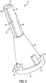
FIG. 3 is a side perspective view of the coupling member of the toothbrush head according to the embodiments inFIG. 1 . -
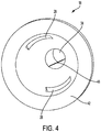
FIG. 4 is a bottom perspective view of the coupling member of the toothbrush head according to the embodiments inFIG. 1 . -
FIG. 5 is a bottom perspective view of the stem of the toothbrush head according to the embodiments inFIG. 1 . -
FIG. 6 is a wireframe of the stem of the toothbrush head according to the embodiments inFIG. 1 . -
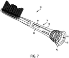
FIG. 7 is a transparent view of the toothbrush head with the stem therein according to the embodiments inFIG. 1 . - This disclosure is not limited to the particular systems, methodologies or protocols described, as these may vary. The terminology used in this description is for the purpose of describing the particular versions or embodiments only, and is not intended to limit the scope.
- In some embodiments, a
brush head 10 is couplable to a drive shaft of an electric toothbrush handle, as shown inFIG. 1 . Thebrush head 10 includes abrush section 12 that hasmultiple bristles 16 attached thereon. Thebrush head 10 also has astem 14, which extends from thebrush section 12. Thestem 14 has an opening therein (15 inFIG. 5 ) for receiving and mounting acoupling member 18. The attachment of thecoupling member 18 to thestem 14 is further described in detail with reference toFIG. 2 . - As shown in
FIG. 2 , according to the invention, thecoupling member 18 has abody 26, which has an opening 27 for receiving a drive shaft of the electric toothbrush handle. Thebody 26 has one or more mountingholes 28 that are positioned to engage with one or more mounting ridges (54 inFIG. 5 ) of the stem so that the coupling member can be mounted to the stem. Thecoupling member 18 also has ahandle coupling section 22, which has awall 24 with anaperture 34 inside the wall. Thewall 24 has at least twolongitudinal slits 36 that form aresilient wall 38 in between. Theresilient wall 38 is positioned to touch the drive shaft when the drive shaft is inserted into the aperture inside thewall 24 and exert a return force inward towards the drive shaft to achieve a tight coupling with the drive shaft. - In the illustrated embodiment, the cross-section of the
coupling section 22 may corresponds to the size of thestem 14 of thebrush head 10, for example, at about 3,18 mm (1/8 inch) in diameter measured from outside, with a length about 12,7 mm (1/2 inch). Thebody 26 may extend from the coupling section and flares outward to theopening 27 to form a cone shape. Theopening 27 may be of various sizes, for example, at 12,7 mm (1/2 inch) in diameter as measured from outside at its widest point. - In various embodiments, multiple engagements between various parts may additionally facilitate the tight coupling between the brush head and the coupling member. For example, in
FIG. 2 , thecoupling member 18 may have one ormore mounting blocks 30 extending from outside thebody 26 and that are positioned to engage with one or more mounting receptacles 56 (inFIG. 5 ) inside the opening 15 (FIG. 5 ) of the stem 14 (FIG. 5 ). This engagement between each mountingblock 30 and its corresponding mounting receptacles 56 (inFIG. 5 ) will further lock the coupling member into position to prevent the coupling member from being pushed in or rotating about the axis of the stem. - Alternatively, and/or additionally, to the mounting blocks as shown in
FIG. 3 , thecoupling member 18 may include ahead section 20, which extends from thehandle coupling section 22 and has alongitudinal ridge 46 on outside surface of the head section and thelongitudinal ridge 46 is positioned to engage with a longitudinal channel inside the stem (shown in 64 inFIG. 6 ). This engagement between thelongitudinal ridge 46 and thelongitudinal channel 64 inside the stem prevents the coupling member from rotational movement about the axis of the stem. It further provides a guide to facilitate the insertion of the coupling member into the stem. Optionally, as shown inFIG. 3 , thelongitudinal ridge 46 may also extend longitudinally from thehead section 20 along outside surface of thewall 24 of thehandle coupling section 22 of the coupling member to further enhance the engagement between the couplingmember 18 and the stem and prevent rotational movement or twisting of the coupling member relative to the stem. - Alternatively, and/or additionally, to the mounting blocks as shown in
FIG. 3 , thehead section 20 may also have a grooved mountingchannel 32, which is positioned to engage with a ridge block 60 (inFIG. 6 ) in the stem to further facilitate the coupling of the coupling member and the stem. Optionally, as shown inFIG. 6 , theridge block 60 inside thestem 14 may have a stoppingedge 62, which is positioned to touch theend 68 of mounting channel 32 (inFIG. 2 ) of the coupling member to prevent the coupling member from further being inserted into inside the stem. - Alternatively, and/or additionally, to the mounting blocks as shown in
FIGs. 2 and5 , theopening 15 of thestem 14 may have a base platform, and theopening 27 of thebody 26 of thecoupling member 18 may also have a base platform that is positioned to be flush with the base platform of the stem when the coupling member and the stem are fully engaged (as shown inFIG. 1 ). - Additionally the
coupling member 18 may have an engagement means for further coupling the brush head to the drive shaft of the toothbrush handle. This engagement means may include a raisedportion 40 that extends inward from theresilient wall 38 and is positioned to touch the drive shaft when the drive shaft is inserted into theaperture 34 of thehandle coupling section 22. The raisedportion 40, when touching the drive shaft, will also raise theresilient wall 38 outward, thus to increase the inward returning force of theresilient wall 38, whereby a tighter coupling between the coupling member and the drive shaft of the electric toothbrush handle can be achieved. - Additionally as shown in
FIG. 4 , the handle coupling section may have a flatengaging surface 48 inside theaperture 34 and is positioned to mate with a flat surface of the drive shaft so that the handle coupling section and the drive shaft can be fully coupled. - Additionally, as shown in
FIGs. 2 and5 , thestem 14 may have a sittingplatform 52 along a portion or all of the inside perimeter of theopening 15, whereas theopening 27 of thebody 26 of thecoupling member 18 has abase ring 44 around a portion or all of the outside perimeter of theopening 27 which is positioned to mate with the sittingplatform 52 of the stem. This mating arrangement will prevent the coupling member from further moving into the stem when it is fully coupled to the stem. This mating arrangement will also make it easier forbase platform 42 of thecoupling member 18 and thebase platform 50 of thestem 14 to flush when they are being assembled together. - Additionally, as shown in
FIG. 2 , theresilient wall 38 thehandle coupling section 22 may raise outward above outside surface of the rest of the wall, while the raisedresilient wall 38 forms a longitudinal guide that is positioned to engage with acoupling channel 66 inside the stem 14 (inFIG. 6 ), to further facilitate the coupling of the coupling member and the stem. In some embodiments, as shown inFIG. 2 , the raisedresilient wall 38 extends from theend 68 of the mountingchannel 32. Correspondingly, as shown inFIG. 6 , thecoupling channel 66 in the stem may extend from the stoppingedge 62 of theridge block 60 longitudinally outward towards the opening (15 inFIG. 5 ) to engage with the raisedresilient wall 38 of the coupling member. - To enable locking of the coupling member to the stem, as shown in
FIG. 3 , thecoupling member 18 may have a lockingridge 29 raising from outside surface of thebody 26 and positioned to engage with the one or more mounting ridges of the stem (54 inFIG. 5 ) so that the coupling member is locked to the stem and prevented from being pushed out of the stem along the axis of the stem. In some embodiments, the mountinghole 28 may have a horizontal edge that is substantially parallel to the plane formed by thebase platform 42. The horizontal edge of the mounting hole may also form a width of the opening of the mounting hole. In some embodiments, the lockingridge 29 may be curved or arched along the horizontal edge of the opening of the mountinghole 28. The length of the lockingridge 29 may also be of substantially the same as the width of the opening of the mounting hole. With reference to bothFIGs. 3 and5 , the mountingridge 54 may also have a horizontal edge that is substantially parallel to the plane formed by the basedplatform 50 of thestem 14. The horizontal edge of the mounting ridge may be positioned to engage with the lockingridge 29 of thecoupling member 18 when the coupling member is secured inside the stem. In such a way, the lockingridge 29 is positioned to prevent the mountingridge 54 from coming out of the mountinghole 28 due to vibration of the toothbrush when in operation, so that thecoupling member 18 can be secured inside thestem 14. - As shown in
FIGs. 2 and5 , at least a portion of thehead section 20 and/or thehandle coupling section 22 of thecoupling member 18 are in a cylindrical shape. Thebody 26 of thecoupling member 18 is in a cone shape near theopening 27 and a portion of the stem proximate to theopening 15 also has a cone shape that corresponds to the cone shape of thebody 26 of thecoupling member 18 so that the stem may receive the coupling member into itsopening 15. - The various embodiments disclosed in this patent document provide advantages over the prior art, whether standalone or combined. For example, the resilient wall of the handle coupling section of the coupling member that is positioned to engage with the drive shaft of the electric toothbrush handle may be made from the same wall of the handle coupling section of the coupling member, which requires no metal spring or other separate resilient member. This both achieves a tight coupling (because there is no separate part) and reduces the cost of making. Further, multiple engagements of various parts of the stem and the coupling member all facilitate a tight coupling between the coupling member and the stem, and thus improve the stability of the brush head as it is operating under the high speed vibrations of the motor inside the handle.
- Further, the toothbrush head may be easy to manufacture as all the parts can be made of plastic or polyester materials. The cone shaped opening of the stem may facilitate easy receiving and coupling of the coupling member into the stem, and multiple engagement means, such as, the longitudinal ridge of the coupling member and the corresponding longitudinal channel in the stem, the mounting channel of the coupling member and the corresponding ridge block in the stem, the raised resilient wall of the coupling member and the corresponding coupling channel in the stem, the mounting block of the coupling member and the corresponding mounting channel in the stem, the base ring of the coupling member and the mating sitting platform in the stem, the mounting holes of the coupling member and the mounting ridges in the stem, each may facilitate easy sliding and positioning of the coupling member into the stem and secure mounting of the coupling member to the stem.
Claims (8)
- A toothbrush head comprising:a brush section (12) having a plurality of bristles (16) attached thereon;a stem (14) extending from the brush section, wherein the stem defines an opening (15) therein and comprises one or more mounting ridges (54) on inside wall of the opening; anda coupling member (18) mountable to inside the opening (15) of the stem (14), wherein the coupling member (18) comprises:a cone body (26) having:an opening (27) configured proximate to an electric toothbrush handle, configured to receive a drive shaft of the electric toothbrush handle into the coupling member (18), andone or more mounting holes (28) that are positioned to engage with the one or more mounting ridges (54) of the stem (14) to secure the coupling member (18) to the stem (14) in position,wherein the coupling member (18) further comprises:a cylindrical handle coupling section (22) extending at one end from the cone body (26) opposite to the opening (27) and having a wall (24) and defining an aperture (34) within the wall (24) for receiving the drive shaft, wherein the wall (24) has at least two longitudinal slits (36) and a resilient wall (38) between the two slits, further wherein the resilient wall (38) is positioned to engage with the drive shaft when the drive shaft is inserted into the coupling member (18).
- The toothbrush head of claim 1, wherein:the stem (14) further comprises a ridge block (60) and a longitudinal channel (64) on the inside wall of the opening (15); andthe coupling member (18) further comprises a head section (20) extending from the cylindrical handle coupling section (22), wherein the head section (20) has a longitudinal ridge (46) that is positioned to engage with the longitudinal channel (64) of the stem (14), wherein the head section (20) also defines a mounting channel (32) that is positioned to engage with the ridge block (60) of the stem (14).
- The toothbrush head of any one of claims 1-2, wherein:the opening of the stem (14) has a base platform (60); andthe opening of the cone body (26) of the coupling member (18) has a base platform (42) that is positioned to be flush with the base platform (60) of the stem (14).
- The toothbrush head of any one of claims 1-3, wherein the resilient wall (38) of the cylindrical handle coupling section (22) has a raised portion (40) extending inward and positioned to touch the drive shaft so that the drive shaft is tightly coupled to the cylindrical handle coupling section (22) while received in the aperture (34) of the cylindrical handle coupling section (22).
- The toothbrush head of any one of claims 1-4, wherein the cylindrical handle coupling section (22) defines a flat engaging surface (48) inside the aperture (34) that is positioned to mate with a flat surface of the drive shaft.
- The toothbrush head of any one of claims 1-5, wherein:the stem (14) defines a sitting platform (52) along at least a portion of an inside perimeter of the opening (15) of the stem (14); andthe cone body (26) of the coupling member (18) has a base ring (44) around at least a portion of an outside perimeter of the opening (27) of the cone body (26) and positioned to mate with the sitting platform (52) of the stem (14).
- The toothbrush head of any one of claims 1-6, wherein:the stem (14) further comprises a coupling channel (66) on an inside surface; andthe resilient wall (38) of the cylindrical handle coupling section (22) raises outward from the cylindrical handle coupling section (22) and forms a guide that is positioned to engage with the coupling channel (66) of the stem (14).
- The toothbrush head of any one of claims 1-7, wherein the cone body (26) of the coupling member (18) has a locking ridge (29) raising from an outside surface of the cone body (26) along a horizontal edge of an opening of the one or more mounting holes (28) and positioned to engage with a horizontal edge of the one or more mounting ridges (54) of the stem (14) so that the coupling member (18) is locked unto the stem (14).
Priority Applications (1)
| Application Number | Priority Date | Filing Date | Title |
|---|---|---|---|
| EP21190823.1A EP3925571B1 (en) | 2017-01-06 | 2017-03-22 | Brush head for electric toothbrush |
Applications Claiming Priority (2)
| Application Number | Priority Date | Filing Date | Title |
|---|---|---|---|
| US15/400,369 US9724180B1 (en) | 2017-01-06 | 2017-01-06 | Brush head for electric toothbrush |
| PCT/IB2017/000377 WO2018127728A1 (en) | 2017-01-06 | 2017-03-22 | Brush head for electric toothbrush |
Related Child Applications (2)
| Application Number | Title | Priority Date | Filing Date |
|---|---|---|---|
| EP21190823.1A Division-Into EP3925571B1 (en) | 2017-01-06 | 2017-03-22 | Brush head for electric toothbrush |
| EP21190823.1A Division EP3925571B1 (en) | 2017-01-06 | 2017-03-22 | Brush head for electric toothbrush |
Publications (3)
| Publication Number | Publication Date |
|---|---|
| EP3565503A1 EP3565503A1 (en) | 2019-11-13 |
| EP3565503A4 EP3565503A4 (en) | 2020-09-23 |
| EP3565503B1 true EP3565503B1 (en) | 2021-11-10 |
Family
ID=59411347
Family Applications (2)
| Application Number | Title | Priority Date | Filing Date |
|---|---|---|---|
| EP17889959.7A Active EP3565503B1 (en) | 2017-01-06 | 2017-03-22 | Brush head for electric toothbrush |
| EP21190823.1A Active EP3925571B1 (en) | 2017-01-06 | 2017-03-22 | Brush head for electric toothbrush |
Family Applications After (1)
| Application Number | Title | Priority Date | Filing Date |
|---|---|---|---|
| EP21190823.1A Active EP3925571B1 (en) | 2017-01-06 | 2017-03-22 | Brush head for electric toothbrush |
Country Status (4)
| Country | Link |
|---|---|
| US (2) | US9724180B1 (en) |
| EP (2) | EP3565503B1 (en) |
| JP (1) | JP6670980B2 (en) |
| WO (1) | WO2018127728A1 (en) |
Families Citing this family (48)
| Publication number | Priority date | Publication date | Assignee | Title |
|---|---|---|---|---|
| EP3534830B1 (en) | 2016-11-03 | 2021-06-02 | Papazian, Mihran | Replacement toothbrush head assembly for toothbrushing systems |
| AU201712649S (en) | 2016-11-22 | 2017-05-22 | Braun Gmbh | Toothbrush Head |
| USD830699S1 (en) * | 2017-02-03 | 2018-10-16 | Harria Investment Group Ltd. | Brush head for an electric toothbrush |
| CN109223230B (en) * | 2017-07-11 | 2020-09-25 | Js控股股份有限公司 | Removable brush head for a power toothbrush |
| USD849408S1 (en) * | 2017-12-12 | 2019-05-28 | Colgate-Palmolive Company | Replacement head for an oral care implement |
| USD846883S1 (en) | 2017-12-12 | 2019-04-30 | Colgate-Palmolive Company | Handle of an oral care implement |
| US10709533B2 (en) | 2017-12-12 | 2020-07-14 | Colgate-Palmolive Company | Oral care implement and handle and refill head thereof |
| US10631964B2 (en) | 2017-12-12 | 2020-04-28 | Colgate-Palmolive Company | Oral care implement |
| USD851938S1 (en) * | 2017-12-12 | 2019-06-25 | Colgate-Palmolive Company | Replacement head for an oral care implement |
| USD912988S1 (en) * | 2018-02-09 | 2021-03-16 | The Gillette Company Llc | Toothbrush handle |
| USD960581S1 (en) * | 2018-02-09 | 2022-08-16 | The Gillette Company Llc | Toothbrush head |
| USD869855S1 (en) | 2018-07-24 | 2019-12-17 | Burst.USA Inc. | Toothbrush handle |
| USD931617S1 (en) | 2018-09-03 | 2021-09-28 | The Gillette Company Llc | Toothbrush head |
| USD891784S1 (en) | 2018-12-18 | 2020-08-04 | Colgate-Palmolive Company | Electric toothbrush handle |
| USD887145S1 (en) * | 2019-01-27 | 2020-06-16 | Shenzhen Ya Bei Kang Technology Co., Ltd. | Electric toothbrush head |
| CN110151348B (en) * | 2019-03-14 | 2024-04-19 | 胡斐凡 | Brush head assembly and electric toothbrush |
| USD901183S1 (en) | 2019-03-22 | 2020-11-10 | The Gillette Company Llc | Toothbrush |
| USD935192S1 (en) * | 2019-08-30 | 2021-11-09 | Shenzhen Baolijie Technology Co., Ltd. | Electric toothbrush head |
| USD935193S1 (en) * | 2019-08-30 | 2021-11-09 | Shenzhen Baolijie Technology Co., Ltd. | Electric toothbrush head |
| EP3865088B1 (en) | 2020-02-17 | 2023-07-26 | Trisa Holding AG | Push-on brush device |
| USD972302S1 (en) | 2020-03-13 | 2022-12-13 | Ranir, Llc | Toothbrush drive unit |
| US11311096B2 (en) * | 2020-03-18 | 2022-04-26 | Water Pik, Inc. | Brush head for an oral cleansing device |
| USD895977S1 (en) * | 2020-04-21 | 2020-09-15 | Juanyun Kuang | Toothbrush head |
| USD895976S1 (en) * | 2020-04-22 | 2020-09-15 | Xiufeng Li | Toothbrush head |
| USD957135S1 (en) | 2020-07-02 | 2022-07-12 | The Gillette Company Llc | Toothbrush head |
| USD1014095S1 (en) | 2020-07-02 | 2024-02-13 | The Gillette Company Llc. | Toothbrush |
| USD954441S1 (en) | 2020-07-20 | 2022-06-14 | Js Holding Inc. | Brush head for electric toothbrush |
| US12201493B2 (en) | 2020-07-20 | 2025-01-21 | Oralic Supplies Inc. | Structure for coupling toothbrush head to electric toothbrush handle |
| US11071612B1 (en) * | 2020-07-20 | 2021-07-27 | Js Holding Inc. | Structure for coupling toothbrush head to electric toothbrush handle |
| US11666137B2 (en) | 2020-08-07 | 2023-06-06 | Juan-Yun Kuang | Brushhead for power toothbrush |
| US11413126B2 (en) | 2020-08-07 | 2022-08-16 | Juan-Yun Kuang | Brushhead for power toothbrush |
| US10912377B1 (en) | 2020-08-07 | 2021-02-09 | Juan-Yun Kuang | Electric toothbrush brush head and electric toothbrush |
| US11439488B2 (en) * | 2020-08-07 | 2022-09-13 | Juan-Yun Kuang | Brushhead for power toothbrush |
| CA218833S (en) | 2020-11-06 | 2023-11-08 | Gillette Co Llc | Toothbrush head |
| USD960582S1 (en) | 2020-12-10 | 2022-08-16 | Colgate-Palmolive Company | Oral care refill head |
| US12458479B2 (en) | 2020-12-10 | 2025-11-04 | Colgate-Palmolive Company | Oral care implement and handle thereof |
| USD971611S1 (en) | 2020-12-17 | 2022-12-06 | Chunyang Liu | Toothbrush head |
| USD933965S1 (en) * | 2021-01-14 | 2021-10-26 | Guocheng Tang | Toothbrush head |
| USD1051608S1 (en) | 2021-05-04 | 2024-11-19 | The Gillette Company Llc | Handle for battery operated toothbrush |
| USD1033910S1 (en) | 2021-07-02 | 2024-07-09 | Braun Gmbh | Handle for electric toothbrush |
| BR102021018859B1 (en) * | 2021-09-22 | 2022-05-03 | Marli Sala | Oral hygiene brush, with bristle head replacement system |
| USD965301S1 (en) | 2022-04-07 | 2022-10-04 | Shengzhou Li | Toothbrush head |
| USD970895S1 (en) | 2022-04-07 | 2022-11-29 | Shengzhou Li | Toothbrush head |
| USD1041905S1 (en) | 2022-04-07 | 2024-09-17 | Ting Cao | Toothbrush head |
| USD1054704S1 (en) | 2022-04-07 | 2024-12-24 | Ting Cao | Brush head |
| US12514692B2 (en) * | 2022-04-20 | 2026-01-06 | Oralic Supplies, Inc. | Structure for coupling toothbrush head to electric toothbrush handle |
| USD977256S1 (en) * | 2022-08-24 | 2023-02-07 | Guangdong Meihong Dental Technology Co., Ltd. | Electric toothbrush |
| USD981721S1 (en) * | 2022-10-31 | 2023-03-28 | Xiangyu Huang | Toothbrush replacement head |
Citations (12)
| Publication number | Priority date | Publication date | Assignee | Title |
|---|---|---|---|---|
| DE2527130A1 (en) | 1974-06-27 | 1976-01-15 | Lpa Les Produits Associes | PLUG-ON DEVICE FOR THE INSTRUMENTS OF A BODY CARE DEVICE |
| DE3937853A1 (en) | 1989-11-14 | 1991-05-16 | Braun Ag | ELECTRIC TOOTHBRUSH WITH DETACHABLE BRUSH PART |
| US5617601A (en) | 1993-10-08 | 1997-04-08 | Mcdougall; Gregory J. | Brushes for personal hygiene purposes |
| JPH1052447A (en) | 1996-08-09 | 1998-02-24 | Eiji Okada | Mounting structure for brush body of electric tooth brush |
| DE10159395A1 (en) | 2001-12-04 | 2003-06-12 | Braun Gmbh | Device for cleaning teeth |
| WO2005046506A1 (en) | 2003-11-13 | 2005-05-26 | Braun Gmbh | Brush part for an electric toothbrush |
| EP2234561A1 (en) | 2007-12-18 | 2010-10-06 | Koninklijke Philips Electronics N.V. | A brushhead/handle interface for a power toothbrush |
| WO2013104020A1 (en) | 2012-01-13 | 2013-07-18 | Erskine Products Pty Ltd | A dental hygiene item |
| CN103764066A (en) | 2011-10-19 | 2014-04-30 | 松下电器产业株式会社 | Oral Hygiene Devices |
| US20150082560A1 (en) | 2013-09-24 | 2015-03-26 | M+C Schiffer Gmbh | Brush Head Attachment |
| WO2015147054A1 (en) | 2014-03-28 | 2015-10-01 | サンスター株式会社 | Electrically driven toothbrush |
| CN205698093U (en) | 2016-04-14 | 2016-11-23 | 爱芽(北京)科技有限公司 | Electric toothbrush drive shaft and electric toothbrush thereof |
Family Cites Families (26)
| Publication number | Priority date | Publication date | Assignee | Title |
|---|---|---|---|---|
| US3369265A (en) * | 1966-07-07 | 1968-02-20 | Vistron Corp | Universal toothbrush head |
| JPS5321650B2 (en) * | 1973-10-31 | 1978-07-04 | ||
| JPS5937082B2 (en) * | 1976-08-11 | 1984-09-07 | 松下電工株式会社 | electric toothbrush |
| DE3129435A1 (en) * | 1981-07-25 | 1983-02-10 | Braun Ag, 6000 Frankfurt | Attachable device for instruments of a body care appliance |
| BE1007374A3 (en) * | 1993-07-30 | 1995-05-30 | Philips Electronics Nv | Toothbrush. |
| DE19745876A1 (en) * | 1997-10-17 | 1999-04-22 | Braun Ag | Brush part for electric toothbrush |
| WO2000076420A1 (en) * | 1999-06-10 | 2000-12-21 | Gimelli Produktions Ag | Slip-on brush designed for a hand part of an electric toothbrush |
| JP3096312U (en) * | 2003-03-06 | 2003-09-12 | 正傑 江 | Electric toothbrush brush head |
| DE102005041459A1 (en) * | 2005-08-31 | 2007-03-01 | Braun Gmbh | Gum massage brush head for use in tooth brush, has massage units made of soft material and protruding from operating side of head, where units have hardness of less than fifty shores and shape that is stably movable with certain hertz |
| DE102006060134A1 (en) * | 2006-12-18 | 2008-06-19 | Braun Gmbh | Toothbrush and attachment for this purpose |
| USD563674S1 (en) | 2007-01-18 | 2008-03-11 | Koninklijke Philips Electronics N.V. | Toothbrush |
| DE102007022827A1 (en) * | 2007-05-15 | 2008-11-20 | Braun Gmbh | Toothbrush attachment and method for its production |
| USD569623S1 (en) | 2007-05-24 | 2008-05-27 | Koninklijke Philips Electroncis N. V. | Toothbrush |
| CN101642388A (en) * | 2008-01-29 | 2010-02-10 | 黄拔梓 | Electric toothbrush head device |
| US20110107536A1 (en) * | 2008-07-02 | 2011-05-12 | Koninklijke Philips Electronics N.V. | Brushhead assembly for a power toothbrush |
| USD653035S1 (en) | 2010-04-20 | 2012-01-31 | Koninklijke Philips Electronics N.V. | Brush head for electric toothbrush |
| JP2012005659A (en) * | 2010-06-24 | 2012-01-12 | Panasonic Electric Works Co Ltd | Tooth cleaning device |
| USD696517S1 (en) | 2010-11-30 | 2013-12-31 | Koninklijke Philips N.V. | Electric toothbrush |
| CA140611S (en) | 2010-11-30 | 2012-01-27 | Philips Electronics Ltd | Charger for electric toothbrush |
| CN103260465B (en) | 2010-12-20 | 2016-01-06 | 皇家飞利浦电子股份有限公司 | There is the oral hygiene appliance for effectively clean bristle feature |
| WO2012085752A1 (en) | 2010-12-20 | 2012-06-28 | Koninklijke Philips Electronics N.V. | Brushhead for a power toothbrush with a wedge and spring handle interface |
| WO2013061219A1 (en) * | 2011-10-25 | 2013-05-02 | Koninklijke Philips Electronics N.V. | Brushhead for a power toothbrush with a two position coupling assembly |
| TWD160374S (en) | 2012-10-31 | 2014-05-01 | Koninklijke Philips Electronics Nv | Electric toothbrush |
| JP6445550B2 (en) * | 2013-10-25 | 2019-01-09 | コーニンクレッカ フィリップス エヌ ヴェKoninklijke Philips N.V. | Attachment for electric toothbrush handle and method of attachment |
| EP2883516A1 (en) * | 2013-12-12 | 2015-06-17 | Braun GmbH | Electric toothbrush |
| US10376348B2 (en) * | 2014-07-02 | 2019-08-13 | Koninklijke Philips N.V. | Shaft for an automatic toothbrush |
-
2017
- 2017-01-06 US US15/400,369 patent/US9724180B1/en active Active
- 2017-01-10 US US15/402,298 patent/US9827079B1/en active Active
- 2017-03-22 EP EP17889959.7A patent/EP3565503B1/en active Active
- 2017-03-22 WO PCT/IB2017/000377 patent/WO2018127728A1/en not_active Ceased
- 2017-03-22 JP JP2019537087A patent/JP6670980B2/en active Active
- 2017-03-22 EP EP21190823.1A patent/EP3925571B1/en active Active
Patent Citations (12)
| Publication number | Priority date | Publication date | Assignee | Title |
|---|---|---|---|---|
| DE2527130A1 (en) | 1974-06-27 | 1976-01-15 | Lpa Les Produits Associes | PLUG-ON DEVICE FOR THE INSTRUMENTS OF A BODY CARE DEVICE |
| DE3937853A1 (en) | 1989-11-14 | 1991-05-16 | Braun Ag | ELECTRIC TOOTHBRUSH WITH DETACHABLE BRUSH PART |
| US5617601A (en) | 1993-10-08 | 1997-04-08 | Mcdougall; Gregory J. | Brushes for personal hygiene purposes |
| JPH1052447A (en) | 1996-08-09 | 1998-02-24 | Eiji Okada | Mounting structure for brush body of electric tooth brush |
| DE10159395A1 (en) | 2001-12-04 | 2003-06-12 | Braun Gmbh | Device for cleaning teeth |
| WO2005046506A1 (en) | 2003-11-13 | 2005-05-26 | Braun Gmbh | Brush part for an electric toothbrush |
| EP2234561A1 (en) | 2007-12-18 | 2010-10-06 | Koninklijke Philips Electronics N.V. | A brushhead/handle interface for a power toothbrush |
| CN103764066A (en) | 2011-10-19 | 2014-04-30 | 松下电器产业株式会社 | Oral Hygiene Devices |
| WO2013104020A1 (en) | 2012-01-13 | 2013-07-18 | Erskine Products Pty Ltd | A dental hygiene item |
| US20150082560A1 (en) | 2013-09-24 | 2015-03-26 | M+C Schiffer Gmbh | Brush Head Attachment |
| WO2015147054A1 (en) | 2014-03-28 | 2015-10-01 | サンスター株式会社 | Electrically driven toothbrush |
| CN205698093U (en) | 2016-04-14 | 2016-11-23 | 爱芽(北京)科技有限公司 | Electric toothbrush drive shaft and electric toothbrush thereof |
Non-Patent Citations (1)
| Title |
|---|
| ANNINA HAGE: "Untersuchungen zur Keimbesiedlung von elektrischen Zahnbürsten - ein Vergleich zwischen Schall- und rotierend-oszillierenden Zahnbürsten", DISSERTATION, 2010, Göttingen, XP055842367, Retrieved from the Internet <URL:https://ediss.uni- goettingen.de/bitstream/handle/11858/00-1735-0000-0006-B 1 0A-C/hage_a.pdf ?sequence=1> |
Also Published As
| Publication number | Publication date |
|---|---|
| EP3925571B1 (en) | 2023-07-26 |
| US9724180B1 (en) | 2017-08-08 |
| JP2020503150A (en) | 2020-01-30 |
| WO2018127728A1 (en) | 2018-07-12 |
| JP6670980B2 (en) | 2020-03-25 |
| EP3565503A4 (en) | 2020-09-23 |
| EP3925571C0 (en) | 2023-07-26 |
| US9827079B1 (en) | 2017-11-28 |
| EP3565503A1 (en) | 2019-11-13 |
| EP3925571A1 (en) | 2021-12-22 |
Similar Documents
| Publication | Publication Date | Title |
|---|---|---|
| EP3565503B1 (en) | Brush head for electric toothbrush | |
| JP7754520B2 (en) | Structure for connecting a toothbrush head to an electric toothbrush handle | |
| AU2021202083B2 (en) | Electric toothbrush | |
| JP7451692B2 (en) | Mounting part of replacement head for electric toothbrush | |
| US10869742B2 (en) | Coupling mechanism for electric toothbrush | |
| US9597169B2 (en) | Brushhead for a power toothbrush with a two position coupling assembly | |
| EP3644896A1 (en) | Refill for electric toothbrush | |
| US8484850B2 (en) | Hair remover | |
| EP3240499B1 (en) | Electric toothbrush | |
| KR200470899Y1 (en) | Improved Lipstick Middle Tube-assembling Structure | |
| US20250114180A1 (en) | Structure for Coupling Toothbrush Head to Electric Toothbrush Handle | |
| US12514692B2 (en) | Structure for coupling toothbrush head to electric toothbrush handle | |
| JP3184323U (en) | Primary ring removal jig for rotary pump | |
| IL206066A (en) | Poultry de-feathering apparatus | |
| KR20170091957A (en) | A hand blender comprising detachable blade |
Legal Events
| Date | Code | Title | Description |
|---|---|---|---|
| STAA | Information on the status of an ep patent application or granted ep patent |
Free format text: STATUS: THE INTERNATIONAL PUBLICATION HAS BEEN MADE |
|
| PUAI | Public reference made under article 153(3) epc to a published international application that has entered the european phase |
Free format text: ORIGINAL CODE: 0009012 |
|
| STAA | Information on the status of an ep patent application or granted ep patent |
Free format text: STATUS: REQUEST FOR EXAMINATION WAS MADE |
|
| 17P | Request for examination filed |
Effective date: 20190726 |
|
| AK | Designated contracting states |
Kind code of ref document: A1 Designated state(s): AL AT BE BG CH CY CZ DE DK EE ES FI FR GB GR HR HU IE IS IT LI LT LU LV MC MK MT NL NO PL PT RO RS SE SI SK SM TR |
|
| AX | Request for extension of the european patent |
Extension state: BA ME |
|
| RAP1 | Party data changed (applicant data changed or rights of an application transferred) |
Owner name: JS HOLDING INC. |
|
| DAV | Request for validation of the european patent (deleted) | ||
| DAX | Request for extension of the european patent (deleted) | ||
| A4 | Supplementary search report drawn up and despatched |
Effective date: 20200821 |
|
| RIC1 | Information provided on ipc code assigned before grant |
Ipc: A61C 17/34 20060101ALI20200817BHEP Ipc: A46B 13/02 20060101ALI20200817BHEP Ipc: A61C 17/22 20060101AFI20200817BHEP |
|
| TPAC | Observations filed by third parties |
Free format text: ORIGINAL CODE: EPIDOSNTIPA |
|
| GRAP | Despatch of communication of intention to grant a patent |
Free format text: ORIGINAL CODE: EPIDOSNIGR1 |
|
| STAA | Information on the status of an ep patent application or granted ep patent |
Free format text: STATUS: GRANT OF PATENT IS INTENDED |
|
| INTG | Intention to grant announced |
Effective date: 20210519 |
|
| TPAC | Observations filed by third parties |
Free format text: ORIGINAL CODE: EPIDOSNTIPA |
|
| TPAC | Observations filed by third parties |
Free format text: ORIGINAL CODE: EPIDOSNTIPA |
|
| TPAC | Observations filed by third parties |
Free format text: ORIGINAL CODE: EPIDOSNTIPA |
|
| TPAC | Observations filed by third parties |
Free format text: ORIGINAL CODE: EPIDOSNTIPA |
|
| GRAS | Grant fee paid |
Free format text: ORIGINAL CODE: EPIDOSNIGR3 |
|
| RIN1 | Information on inventor provided before grant (corrected) |
Inventor name: LIU, XINLAN |
|
| GRAA | (expected) grant |
Free format text: ORIGINAL CODE: 0009210 |
|
| STAA | Information on the status of an ep patent application or granted ep patent |
Free format text: STATUS: THE PATENT HAS BEEN GRANTED |
|
| AK | Designated contracting states |
Kind code of ref document: B1 Designated state(s): AL AT BE BG CH CY CZ DE DK EE ES FI FR GB GR HR HU IE IS IT LI LT LU LV MC MK MT NL NO PL PT RO RS SE SI SK SM TR |
|
| REG | Reference to a national code |
Ref country code: DE Ref legal event code: R026 Ref document number: 602017049278 Country of ref document: DE Ref country code: GB Ref legal event code: FG4D |
|
| REG | Reference to a national code |
Ref country code: AT Ref legal event code: REF Ref document number: 1445351 Country of ref document: AT Kind code of ref document: T Effective date: 20211115 Ref country code: CH Ref legal event code: EP |
|
| PLBI | Opposition filed |
Free format text: ORIGINAL CODE: 0009260 |
|
| REG | Reference to a national code |
Ref country code: DE Ref legal event code: R096 Ref document number: 602017049278 Country of ref document: DE |
|
| REG | Reference to a national code |
Ref country code: IE Ref legal event code: FG4D |
|
| REG | Reference to a national code |
Ref country code: FI Ref legal event code: MDE Opponent name: ZIEGLER, TIMO |
|
| 26 | Opposition filed |
Opponent name: ZIEGLER, TIMO Effective date: 20211110 |
|
| REG | Reference to a national code |
Ref country code: LT Ref legal event code: MG9D |
|
| REG | Reference to a national code |
Ref country code: NL Ref legal event code: MP Effective date: 20211110 |
|
| REG | Reference to a national code |
Ref country code: AT Ref legal event code: MK05 Ref document number: 1445351 Country of ref document: AT Kind code of ref document: T Effective date: 20211110 |
|
| PG25 | Lapsed in a contracting state [announced via postgrant information from national office to epo] |
Ref country code: RS Free format text: LAPSE BECAUSE OF FAILURE TO SUBMIT A TRANSLATION OF THE DESCRIPTION OR TO PAY THE FEE WITHIN THE PRESCRIBED TIME-LIMIT Effective date: 20211110 Ref country code: LT Free format text: LAPSE BECAUSE OF FAILURE TO SUBMIT A TRANSLATION OF THE DESCRIPTION OR TO PAY THE FEE WITHIN THE PRESCRIBED TIME-LIMIT Effective date: 20211110 Ref country code: FI Free format text: LAPSE BECAUSE OF FAILURE TO SUBMIT A TRANSLATION OF THE DESCRIPTION OR TO PAY THE FEE WITHIN THE PRESCRIBED TIME-LIMIT Effective date: 20211110 Ref country code: BG Free format text: LAPSE BECAUSE OF FAILURE TO SUBMIT A TRANSLATION OF THE DESCRIPTION OR TO PAY THE FEE WITHIN THE PRESCRIBED TIME-LIMIT Effective date: 20220210 Ref country code: AT Free format text: LAPSE BECAUSE OF FAILURE TO SUBMIT A TRANSLATION OF THE DESCRIPTION OR TO PAY THE FEE WITHIN THE PRESCRIBED TIME-LIMIT Effective date: 20211110 |
|
| PG25 | Lapsed in a contracting state [announced via postgrant information from national office to epo] |
Ref country code: IS Free format text: LAPSE BECAUSE OF FAILURE TO SUBMIT A TRANSLATION OF THE DESCRIPTION OR TO PAY THE FEE WITHIN THE PRESCRIBED TIME-LIMIT Effective date: 20220310 Ref country code: SE Free format text: LAPSE BECAUSE OF FAILURE TO SUBMIT A TRANSLATION OF THE DESCRIPTION OR TO PAY THE FEE WITHIN THE PRESCRIBED TIME-LIMIT Effective date: 20211110 Ref country code: PT Free format text: LAPSE BECAUSE OF FAILURE TO SUBMIT A TRANSLATION OF THE DESCRIPTION OR TO PAY THE FEE WITHIN THE PRESCRIBED TIME-LIMIT Effective date: 20220310 Ref country code: PL Free format text: LAPSE BECAUSE OF FAILURE TO SUBMIT A TRANSLATION OF THE DESCRIPTION OR TO PAY THE FEE WITHIN THE PRESCRIBED TIME-LIMIT Effective date: 20211110 Ref country code: NO Free format text: LAPSE BECAUSE OF FAILURE TO SUBMIT A TRANSLATION OF THE DESCRIPTION OR TO PAY THE FEE WITHIN THE PRESCRIBED TIME-LIMIT Effective date: 20220210 Ref country code: NL Free format text: LAPSE BECAUSE OF FAILURE TO SUBMIT A TRANSLATION OF THE DESCRIPTION OR TO PAY THE FEE WITHIN THE PRESCRIBED TIME-LIMIT Effective date: 20211110 Ref country code: LV Free format text: LAPSE BECAUSE OF FAILURE TO SUBMIT A TRANSLATION OF THE DESCRIPTION OR TO PAY THE FEE WITHIN THE PRESCRIBED TIME-LIMIT Effective date: 20211110 Ref country code: HR Free format text: LAPSE BECAUSE OF FAILURE TO SUBMIT A TRANSLATION OF THE DESCRIPTION OR TO PAY THE FEE WITHIN THE PRESCRIBED TIME-LIMIT Effective date: 20211110 Ref country code: GR Free format text: LAPSE BECAUSE OF FAILURE TO SUBMIT A TRANSLATION OF THE DESCRIPTION OR TO PAY THE FEE WITHIN THE PRESCRIBED TIME-LIMIT Effective date: 20220211 Ref country code: ES Free format text: LAPSE BECAUSE OF FAILURE TO SUBMIT A TRANSLATION OF THE DESCRIPTION OR TO PAY THE FEE WITHIN THE PRESCRIBED TIME-LIMIT Effective date: 20211110 |
|
| PG25 | Lapsed in a contracting state [announced via postgrant information from national office to epo] |
Ref country code: SM Free format text: LAPSE BECAUSE OF FAILURE TO SUBMIT A TRANSLATION OF THE DESCRIPTION OR TO PAY THE FEE WITHIN THE PRESCRIBED TIME-LIMIT Effective date: 20211110 Ref country code: SK Free format text: LAPSE BECAUSE OF FAILURE TO SUBMIT A TRANSLATION OF THE DESCRIPTION OR TO PAY THE FEE WITHIN THE PRESCRIBED TIME-LIMIT Effective date: 20211110 Ref country code: RO Free format text: LAPSE BECAUSE OF FAILURE TO SUBMIT A TRANSLATION OF THE DESCRIPTION OR TO PAY THE FEE WITHIN THE PRESCRIBED TIME-LIMIT Effective date: 20211110 Ref country code: EE Free format text: LAPSE BECAUSE OF FAILURE TO SUBMIT A TRANSLATION OF THE DESCRIPTION OR TO PAY THE FEE WITHIN THE PRESCRIBED TIME-LIMIT Effective date: 20211110 Ref country code: DK Free format text: LAPSE BECAUSE OF FAILURE TO SUBMIT A TRANSLATION OF THE DESCRIPTION OR TO PAY THE FEE WITHIN THE PRESCRIBED TIME-LIMIT Effective date: 20211110 Ref country code: CZ Free format text: LAPSE BECAUSE OF FAILURE TO SUBMIT A TRANSLATION OF THE DESCRIPTION OR TO PAY THE FEE WITHIN THE PRESCRIBED TIME-LIMIT Effective date: 20211110 |
|
| PLAX | Notice of opposition and request to file observation + time limit sent |
Free format text: ORIGINAL CODE: EPIDOSNOBS2 |
|
| PLAB | Opposition data, opponent's data or that of the opponent's representative modified |
Free format text: ORIGINAL CODE: 0009299OPPO |
|
| R26 | Opposition filed (corrected) |
Opponent name: ZIEGLER, TIMO Effective date: 20211110 |
|
| PG25 | Lapsed in a contracting state [announced via postgrant information from national office to epo] |
Ref country code: MC Free format text: LAPSE BECAUSE OF FAILURE TO SUBMIT A TRANSLATION OF THE DESCRIPTION OR TO PAY THE FEE WITHIN THE PRESCRIBED TIME-LIMIT Effective date: 20211110 Ref country code: AL Free format text: LAPSE BECAUSE OF FAILURE TO SUBMIT A TRANSLATION OF THE DESCRIPTION OR TO PAY THE FEE WITHIN THE PRESCRIBED TIME-LIMIT Effective date: 20211110 |
|
| REG | Reference to a national code |
Ref country code: CH Ref legal event code: PL |
|
| PG25 | Lapsed in a contracting state [announced via postgrant information from national office to epo] |
Ref country code: SI Free format text: LAPSE BECAUSE OF FAILURE TO SUBMIT A TRANSLATION OF THE DESCRIPTION OR TO PAY THE FEE WITHIN THE PRESCRIBED TIME-LIMIT Effective date: 20211110 |
|
| REG | Reference to a national code |
Ref country code: BE Ref legal event code: MM Effective date: 20220331 |
|
| PLBB | Reply of patent proprietor to notice(s) of opposition received |
Free format text: ORIGINAL CODE: EPIDOSNOBS3 |
|
| PG25 | Lapsed in a contracting state [announced via postgrant information from national office to epo] |
Ref country code: LU Free format text: LAPSE BECAUSE OF NON-PAYMENT OF DUE FEES Effective date: 20220322 Ref country code: LI Free format text: LAPSE BECAUSE OF NON-PAYMENT OF DUE FEES Effective date: 20220331 Ref country code: IE Free format text: LAPSE BECAUSE OF NON-PAYMENT OF DUE FEES Effective date: 20220322 Ref country code: CH Free format text: LAPSE BECAUSE OF NON-PAYMENT OF DUE FEES Effective date: 20220331 |
|
| PG25 | Lapsed in a contracting state [announced via postgrant information from national office to epo] |
Ref country code: BE Free format text: LAPSE BECAUSE OF NON-PAYMENT OF DUE FEES Effective date: 20220331 |
|
| PG25 | Lapsed in a contracting state [announced via postgrant information from national office to epo] |
Ref country code: IT Free format text: LAPSE BECAUSE OF FAILURE TO SUBMIT A TRANSLATION OF THE DESCRIPTION OR TO PAY THE FEE WITHIN THE PRESCRIBED TIME-LIMIT Effective date: 20211110 |
|
| P01 | Opt-out of the competence of the unified patent court (upc) registered |
Effective date: 20230523 |
|
| REG | Reference to a national code |
Ref country code: GB Ref legal event code: 732E Free format text: REGISTERED BETWEEN 20231116 AND 20231122 |
|
| REG | Reference to a national code |
Ref country code: DE Ref legal event code: R081 Ref document number: 602017049278 Country of ref document: DE Owner name: ORALIC SUPPLIES INC., DIAMOND BAR, US Free format text: FORMER OWNER: JS HOLDING INC., DOVER, DE, US Ref country code: DE Ref legal event code: R081 Ref document number: 602017049278 Country of ref document: DE Owner name: ORALIC SUPPLIES INC., CA Free format text: FORMER OWNER: JS HOLDING INC., DOVER, DE, US |
|
| REG | Reference to a national code |
Ref country code: DE Ref legal event code: R081 Ref document number: 602017049278 Country of ref document: DE Owner name: ORALIC SUPPLIES INC., DIAMOND BAR, US Free format text: FORMER OWNER: ORALIC SUPPLIES INC., DIAMOND BAR, CA |
|
| PG25 | Lapsed in a contracting state [announced via postgrant information from national office to epo] |
Ref country code: MK Free format text: LAPSE BECAUSE OF FAILURE TO SUBMIT A TRANSLATION OF THE DESCRIPTION OR TO PAY THE FEE WITHIN THE PRESCRIBED TIME-LIMIT Effective date: 20211110 Ref country code: CY Free format text: LAPSE BECAUSE OF FAILURE TO SUBMIT A TRANSLATION OF THE DESCRIPTION OR TO PAY THE FEE WITHIN THE PRESCRIBED TIME-LIMIT Effective date: 20211110 |
|
| PG25 | Lapsed in a contracting state [announced via postgrant information from national office to epo] |
Ref country code: HU Free format text: LAPSE BECAUSE OF FAILURE TO SUBMIT A TRANSLATION OF THE DESCRIPTION OR TO PAY THE FEE WITHIN THE PRESCRIBED TIME-LIMIT; INVALID AB INITIO Effective date: 20170322 |
|
| PLAB | Opposition data, opponent's data or that of the opponent's representative modified |
Free format text: ORIGINAL CODE: 0009299OPPO |
|
| R26 | Opposition filed (corrected) |
Opponent name: ZIEGLER, TIMO Effective date: 20211110 |
|
| PG25 | Lapsed in a contracting state [announced via postgrant information from national office to epo] |
Ref country code: MT Free format text: LAPSE BECAUSE OF FAILURE TO SUBMIT A TRANSLATION OF THE DESCRIPTION OR TO PAY THE FEE WITHIN THE PRESCRIBED TIME-LIMIT Effective date: 20211110 |
|
| REG | Reference to a national code |
Ref country code: DE Ref legal event code: R100 Ref document number: 602017049278 Country of ref document: DE |
|
| PLCK | Communication despatched that opposition was rejected |
Free format text: ORIGINAL CODE: EPIDOSNREJ1 |
|
| PLBN | Opposition rejected |
Free format text: ORIGINAL CODE: 0009273 |
|
| STAA | Information on the status of an ep patent application or granted ep patent |
Free format text: STATUS: OPPOSITION REJECTED |
|
| 27O | Opposition rejected |
Effective date: 20241010 |
|
| PGFP | Annual fee paid to national office [announced via postgrant information from national office to epo] |
Ref country code: DE Payment date: 20250221 Year of fee payment: 9 |
|
| PGFP | Annual fee paid to national office [announced via postgrant information from national office to epo] |
Ref country code: FR Payment date: 20250314 Year of fee payment: 9 |
|
| PGFP | Annual fee paid to national office [announced via postgrant information from national office to epo] |
Ref country code: GB Payment date: 20250326 Year of fee payment: 9 |
|
| PG25 | Lapsed in a contracting state [announced via postgrant information from national office to epo] |
Ref country code: TR Free format text: LAPSE BECAUSE OF FAILURE TO SUBMIT A TRANSLATION OF THE DESCRIPTION OR TO PAY THE FEE WITHIN THE PRESCRIBED TIME-LIMIT Effective date: 20211110 |