EP3565135A1 - System and method for inverting a radio channel for broadband signals - Google Patents
System and method for inverting a radio channel for broadband signals Download PDFInfo
- Publication number
- EP3565135A1 EP3565135A1 EP18170041.0A EP18170041A EP3565135A1 EP 3565135 A1 EP3565135 A1 EP 3565135A1 EP 18170041 A EP18170041 A EP 18170041A EP 3565135 A1 EP3565135 A1 EP 3565135A1
- Authority
- EP
- European Patent Office
- Prior art keywords
- measurement
- signals
- under test
- device under
- signal
- Prior art date
- Legal status (The legal status is an assumption and is not a legal conclusion. Google has not performed a legal analysis and makes no representation as to the accuracy of the status listed.)
- Granted
Links
Images



Classifications
-
- G—PHYSICS
- G01—MEASURING; TESTING
- G01R—MEASURING ELECTRIC VARIABLES; MEASURING MAGNETIC VARIABLES
- G01R29/00—Arrangements for measuring or indicating electric quantities not covered by groups G01R19/00 - G01R27/00
- G01R29/08—Measuring electromagnetic field characteristics
- G01R29/0864—Measuring electromagnetic field characteristics characterised by constructional or functional features
- G01R29/0871—Complete apparatus or systems; circuits, e.g. receivers or amplifiers
-
- H—ELECTRICITY
- H04—ELECTRIC COMMUNICATION TECHNIQUE
- H04B—TRANSMISSION
- H04B17/00—Monitoring; Testing
- H04B17/10—Monitoring; Testing of transmitters
- H04B17/15—Performance testing
- H04B17/16—Test equipment located at the transmitter
-
- H—ELECTRICITY
- H04—ELECTRIC COMMUNICATION TECHNIQUE
- H04B—TRANSMISSION
- H04B17/00—Monitoring; Testing
- H04B17/0082—Monitoring; Testing using service channels; using auxiliary channels
- H04B17/0087—Monitoring; Testing using service channels; using auxiliary channels using auxiliary channels or channel simulators
-
- H—ELECTRICITY
- H04—ELECTRIC COMMUNICATION TECHNIQUE
- H04B—TRANSMISSION
- H04B17/00—Monitoring; Testing
- H04B17/10—Monitoring; Testing of transmitters
- H04B17/101—Monitoring; Testing of transmitters for measurement of specific parameters of the transmitter or components thereof
- H04B17/104—Monitoring; Testing of transmitters for measurement of specific parameters of the transmitter or components thereof of other parameters, e.g. DC offset, delay or propagation times
-
- H—ELECTRICITY
- H04—ELECTRIC COMMUNICATION TECHNIQUE
- H04B—TRANSMISSION
- H04B17/00—Monitoring; Testing
- H04B17/10—Monitoring; Testing of transmitters
- H04B17/11—Monitoring; Testing of transmitters for calibration
- H04B17/12—Monitoring; Testing of transmitters for calibration of transmit antennas, e.g. of the amplitude or phase
-
- H—ELECTRICITY
- H04—ELECTRIC COMMUNICATION TECHNIQUE
- H04B—TRANSMISSION
- H04B17/00—Monitoring; Testing
- H04B17/30—Monitoring; Testing of propagation channels
- H04B17/309—Measuring or estimating channel quality parameters
- H04B17/364—Delay profiles
-
- H—ELECTRICITY
- H04—ELECTRIC COMMUNICATION TECHNIQUE
- H04B—TRANSMISSION
- H04B17/00—Monitoring; Testing
- H04B17/30—Monitoring; Testing of propagation channels
- H04B17/373—Predicting channel quality or other radio frequency [RF] parameters
-
- H—ELECTRICITY
- H04—ELECTRIC COMMUNICATION TECHNIQUE
- H04B—TRANSMISSION
- H04B17/00—Monitoring; Testing
- H04B17/30—Monitoring; Testing of propagation channels
- H04B17/391—Modelling the propagation channel
-
- H—ELECTRICITY
- H04—ELECTRIC COMMUNICATION TECHNIQUE
- H04B—TRANSMISSION
- H04B17/00—Monitoring; Testing
- H04B17/30—Monitoring; Testing of propagation channels
- H04B17/391—Modelling the propagation channel
- H04B17/3912—Simulation models, e.g. distribution of spectral power density or received signal strength indicator [RSSI] for a given geographic region
Definitions
- the invention relates to a measurement system adapted to invert a radio channel for a broadband signal.
- the system comprises a device under test with at least two antennas, and at least two measurement probes.
- the signals of the measurement probes each comprise a relative delay.
- MIMO multiple-input multiple-output
- OTA over-the-air
- DUT device under test
- R4-66AH-0012 presented at the 3GPP Meeting RAN4#66-AH-MIMO-OTA in Kunststoff, Germany, 12-13 March 2013, by Agilent Technologies , Tri-L Solutions with the title "Incorporating self-interference into the two-stage method" is related to an alternative two-stage method that supports over-the-air measurements.
- the document can be downloaded under the following link: http://www.3gpp.org/ftp/tsg ran/wg4 radio/TSGR4 AHs/TSGR4 66-AH-MIMO-OTA/Docs/.
- the cited document, hereinafter referred to as R4-66AH-0012 discloses that in a first stage the antenna pattern of the device under test (DUT) is measured.
- a calibrated radiated connection in an anechoic chamber is provided instead of using a cable connection as known from the original two-stage method.
- This replacement of the cable connection is achieved by measuring the MIMO propagation conditions in the anechoic chamber between the test system transmit antennas and the device under test (DUT) receive antennas.
- DUT device under test
- the inverse of this channel is then applied to the test signals in order to create a transmission channel representing an identity matrix, whereby a high degree of isolation (>20db) is achieved between the transmit and receive antenna pairs as was naturally the case when using cabled connections.
- the cited document discloses that due to precoding of the transmitted signals it is possible, by calculating the radiated channel matrix and by applying its inverse to the transmitted signals, to create an identity matrix allowing the transmitted signals to be received independently at each antenna, the document is silent regarding the signal properties of the signal to be transmitted, such as bandwidth.
- Document R4-66AH-0012 does not recognize that beside parameters such as amplitude and phase, additional parameters such as path-loss delay, delay/amplitude/phase of multipath components, frequency-dependency and so on have to be considered when performing channel inversion.
- the cited document is silent that with increasing bandwidth the isolation between the transmit- and receive antenna pairs is reduced to values below 20dB. Since bandwidth is anticipated to increase for future communication systems, it is critical to provide a measurement system and method that ensures acceptable isolation parameters even for signals with increasing bandwidths.
- the object of the invention is to provide a measurement system and measurement method, which allow radio channel inversion even for broadband signals.
- a measurement system is adapted to invert a radio channel for a broadband signal comprising a device under test with at least two antennas and comprising at least two measurement probes.
- Said measurement probes are configured to each emit signals shifted in phase and amplitude.
- the signals emitted by the measurement probes are configured such that each of the signals comprises a relative delay.
- the parameter of delay is used.
- the signals emitted by the measurement probes are shifted in phase and amplitude and are delayed such that the signal intended for a specific antenna of the device under test is only received at said specific antenna and cancelled out at the remaining antennas of the device under test.
- the use of the delay as additional parameter to phase and amplitude shifting allows increasing the destructive interference (i.e. isolation) significantly.
- the time delay is necessary to ensure that each antenna of the device under test only receives the desired signals and no other signals that negatively affect the measurement results.
- the additional time delay especially for broadband signals, allows a destructive interference of unwanted signals at each antenna and ensures only the desired signals are received, respectively measured at the specific antenna.
- the delay is determined based on the relative distance between the different antenna and measurement probe combinations.
- the channel inversion of a physical radio channel between antennas of a device under test that shall receive signals (DUT receive antennas) from a measurement probe (probe antennas) is possible even for high bandwidth signals by adding a relative time delay to each signal emitted by the probe antennas, wherein the time delay takes into account the various distances between the different antenna and probe combinations and is therefore suitable to be used for various test setups with different device under test antenna locations and different measurement probe locations.
- the delay is in the range of 0 to 0.5ns.
- At least the measurement probes and the device under test are located within an anechoic chamber.
- the anechoic chamber prevents disturbances from external influences and ensures reproducibility of measurements.
- the number of delayed signals of each one of the measurement probes can be varied.
- the number of delayed signals is increased until a predefined signal compensation is reached.
- increasing the number of delayed signals reduces the amplitude of an unwanted remaining signal. Said remaining signal is called a residual component.
- the amplitude of the residual component is reduced.
- a predefined signal compensation is determined by the defined allowable residual component. If the defined residual component is not small enough, a further delayed signal has to be emitted.
- the number of delayed signals depends on the spatial arrangement between the antennas of the device under test and the measurement probes.
- the measurement system comprises a base station emulator and/or a channel emulator, wherein the channel emulator configures the measurement probes each have a relative time delay.
- a base station and channel emulator which are frequently used in standard setups for performance testing of communication devices, especially for devices for multiple-input multiple-output (MIMO) applications, allows the channel inversion of the physical radio channel between the DUT receive antenna and the probe antennas for signals with higher bandwidth in an easy and cost-effective way. This is just by adapting the channel emulator to generate a relative time delay between signals of the measurement probes. It is also conceivable that the base station emulator triggers the time delay.
- the signals are generated by a signal generator connected to a splitter distributing the signal to the measurement probes.
- At least one measurement probe is connected to a phase shifting unit and an attenuator or amplifier unit and to a signal delay unit to configure the signals emitted by the measurement probe.
- a method for adapting a measurement system to invert a radio channel for a broadband signal comprises the step of configuring measurement probes of a measurement system to each emit signals shifted in phase and amplitude with the aid of a phase shifting and attenuation or amplification unit.
- the method further comprises the step of configuring the signals of the measurement probes such that each signal comprises a relative delay. It is also conceivable that the phase and amplitude shifting functionality and the time delay functionality are implemented within a base station emulation unit or within as channel emulator unit.
- the method further comprises the step of shifting the signals emitted by the measurement probes in phase and amplitude, and delaying the signals emitted by the measurement probes relative to each other such that the signal intended for a specific antenna of a device under test is only received at said specific antenna and cancelled out at the remaining antennas of the device under test.
- the method further comprises the step of determining the delay between each of the measurement probe signals based on the relative distance between the different antenna and measurement probe combinations.
- the relative time delay for each of the measurement probe signals is determined empirically by varying the delay time for each measurement probe signal based on the feedback of the measurement result at the antennas of the device under test.
- the determination of the relative delay time of the measurement probe signals is determined based on measurement results at each device under test antenna.
- Such measurement indicated for the delay time can be the measurement of the power of the signal that shall be received by the device under test antenna, a bit error rate (BER) measurement of the device under test or any other suitable measurement.
- BER bit error rate
- the method further comprises the step of determining a delay in the range of 0 to 0.5ns.
- the method further comprises the step of increasing the number of delayed signals until a predefined signal compensation is reached.
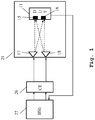
- Fig. 1 an embodiment of a radiated two-stage (RTS) test setup is shown.
- the radiated two-stage method (RTS) measures both, the patterns of the device under test (DUT) and the multiple-input multiple-output (MIMO) throughput performance.
- the setup includes two measurement probes 17, 18, hereinafter also named measurement antennas, probe antennas or measurement antenna probes.
- the setup further includes a user equipment (UE) 11 also named a device under test (DUT) 11 that is equipped with two antennas 15, 16.
- UE user equipment
- the device under test 11 and the measurement probes 17, 18 are located within an anechoic chamber 21.
- the two probe antennas 17, 18 with polarization V and H are co-located within said anechoic chamber 21. Due to the propagation channel between the measurement probes 17, 18 and the antennas 15, 16 of the device under test 11, signals transmitted from each probe antenna 17, 18 are received by each antenna 15, 16 of the user equipment 11.
- the measurement probes 17, 18 are connected to a channel emulator (CE) 26, which is further connected to a base station emulator (BSE) 27.
- the device under test 11 is additionally connected for example via a cable connection or a wireless connection to the base station emulator (BSE) 27.
- the signals generated by the base station emulator (BSE) 27 are modified by the channel emulator (CE) 26 according to a predefined channel model, in order to simulate real-word conditions.
- performance testing of the device under test 11 according to various test standards can be conducted.
- the connection from the device under tests 11 to the base station emulator 27 allows to modify the setting of the base station emulator 27 based on measurements performed by the device under test 11.
- the antenna pattern of the antennas of the device under test is measured with the test setup.
- the transmitted signals are precoded using spatial multiplexing techniques and using results of the antenna pattern measurement, which allows to calculate the radiated channel matrix and to apply the inverse of said radiated channel matrix to the transmitted signals. By doing so, an identity matrix is created allowing the transmitted signals to be received independently at each antenna.
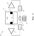
- Fig. 2 shows the device under test (DUT) 11 including two antennas 15, 16.
- the two antennas 15, 16 are located opposite to each other and have a distance d from each other.
- the distance d preferably for example is about 15cm.
- the embodiment further shows a signal generator 28 that is connected to a signal splitter 31 that equally splits the input signal from the signal generator 28 in two output signals.
- the outputs of the signal splitter 31, are each connected to a signal condition unit 29, 30.
- the expression signal condition unit means a unit that includes a phase shifting unit, an attenuator and/or an amplifier unit and further, a signal delay unit.
- the outputs of the signal condition units 29, 30 are each connected to a measurement probe 17 and a measurement probe 18.
- the measurement probes 17, 18 are also called measurement antennas or probe antennas and are preferably located on the opposite walls of an anechoic chamber (not shown).
- each signal condition unit 29, 30 is capable of shifting the amplitude and/or phase of a signal received at its input, and the signal condition unit 29, 30 is additionally capable of delaying the signal received at its input.
- the signal generator 28 preferably generates broadband signals, preferably higher than for example 100MHz.
- Fig. 3 the concept of delaying signals emitted by the measurement probes 17, 18 and the received signals at each antenna 15, 16 of the device under test (DUT) 11 is described based on Fig. 2 .
- Fig. 3 shows a data stream A, emitted by the measurement probe 17 and a data stream B, emitted by the measurement probe 18.
- Data stream A shall be received only by the antenna 15 of the device under test 11, in other words, data stream A shall only be measured at antenna 15.
- Data stream B shall be received only by the antenna 16 of the device under test 11, in other words, data stream B shall only be measured at antenna 16.
- antenna 16 receives a fraction of data stream A, named A', after a time delay ⁇ depending on the distance d between antennas 15 and 16 of the device under test 11, as depicted in Fig. 2 .
- antenna 15 of the device under test 11 receives a fraction of data stream B, named B', after a time delay ⁇ depending on the distance d as depicted in Fig. 2 .
- the fraction of data stream B received at antenna 15 is depicted by a block named B' and the fraction of data stream A received at antenna 16 is depicted by a block named A'.
- the fraction of data stream A, named A' and the fraction of data stream B, named B' are delayed with respect to their originating data streams A and B by a value ⁇ .
- antenna 15 would receive and measure a data stream A and additionally a fraction of a data stream B, named data stream B' having the same orientation as B, but with a reduced amplitude and a time delay ⁇ with respect to data stream B.
- antenna 16 which would receive and measure a data stream B and additionally a fraction of a data stream A, named data stream A' having the same orientation as A, but with a reduced amplitude and a time delay ⁇ with respect to data stream A.
- Data stream B' received at antenna 15 and data stream A' received at antenna 16 are called residual components in case no further data stream is emitted by measurement probe 17 and 18.
- one or more delayed signals are provided by measurement probes 17, 18.
- measurement probe 17 emits a data stream B1, having a time delay ⁇ with respect to data stream A. This is a first delayed signal emitted by measurement probe 17. Said delay depends on the distance d between antenna 15 and 16 of the device under test 11. Data stream B1 has the same amplitude than data stream B' but an opposite orientation, in other words the data stream B1 emitted by measurement probe 17 is phase shifted according to 180° or ⁇ .
- data stream B1 is delayed by ⁇ , data stream B1 and data stream B' are received by antenna 15 of the device under test 11 at the same time. Since said data stream B1 and data stream B' further have the same amplitude and opposite orientation destructive interference is taking place and B' and B1 are cancelled out at antenna 15. This analogously applies for antenna 16, where data stream A1 and data stream A' interfere with each other and any component of data stream A' and A1 is cancelled out at antenna 16.
- a fraction of data stream A1 emitted by measurement probe 18 to compensate for data stream A', is received at antenna 15 having a time delay ⁇ with respect to the data stream A1, having a reduced amplitude compared to A1 and having the same orientation as data stream A1.
- measurement probe 17 emits a data stream A2. This is a second delayed signal emitted by measurement probe 17.
- Said data stream A2 has opposite orientation with respect to A1', but the same amplitude than data stream A1'.
- data stream A2 has a delay ⁇ with respect to data stream B1.
- data stream A2 is delayed by ⁇ , data stream A1' and data stream A2 are received by antenna 15 of the device under test 11 at the same time. Since said data stream A2 and data stream A1' further have the same amplitude and opposite orientation, destructive interference is taking place and A1' and A2 are cancelled out at antenna 15. This analogously applies for antenna 16, where data stream B2 and data stream B1' interfere with each other and any component of data stream B1' and B2 is cancelled out at antenna 16.
- a fraction of data stream B2 emitted by measurement probe 18 is received at antenna 15 having a reduced amplitude compared to data stream B2 and having a delay ⁇ with respect to data stream B2. Since no further compensation signal is emitted by measurement probe 17, the remaining data stream is called residual component B2'.
- a fraction of data stream A2 is received at antenna 16 having a reduced amplitude compared to data stream A2 and having a delay ⁇ with respect to data stream A2. Since no further compensation signal is emitted by measurement probe 18, the remaining data stream is called residual component A2'.
- the number of delayed signals can be increased until a predetermined residual component value is achieved. In other words, the number of delayed signals is increased until a predefined signal compensation is reached.
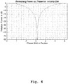
- Fig. 4 to 6 show an embodiment of a simulation of maximum achievable isolation by changing the phase of one probe antenna and for different signal bandwidths based on the measurement setup depicted in Fig. 2 .
- Figs. 4 to 6 show a simulation result for antenna 15 of device under test 11. Due to symmetry in the simulation setup according to Fig. 2 , the results for antenna 16 of device under test 11 are equivalent. In order to investigate maximum achievable isolation, the phase of probe antenna 18 is changed between 0 and 2 ⁇ (2pi). Since path loss is not simulated in this setup, the signals originating from probe 17 and 18 reach antenna 15 of the device under test 11 with the same power. The simulation results show the remaining power after summation of the two signals in relation to the relative phase shift of probe antenna 18. The distance d between the two antennas 15, 16 of the device under test 11 is 15cm in this example.
- the probe antennas 17, 18 are located on the opposite walls of an anechoic chamber (not shown).
- the setup according to Fig. 2 represents the worst case assumption (maximum delay). No reflections are simulated, thus a fully anechoic chamber is assumed. Furthermore, path loss between antenna 15 and 16 of the device under test 11 is ignored, i.e. probe 17 and probe 18 are far away from the device under test 11.
- Fig. 4 shows a simulation result for a small signal bandwidth of 1.4MHz.
- a phase shift of approx. 3,14 radian (Pi) which equals a phase shift of 180°, the remaining power is very small.
- the relative power in dB is -50dB.
- signals with a bandwidth up to 1.4MHz show a clear effect of destructive interference at a phase shift of 180° respectively 3,14 radian (Pi), which means that high isolation values are achievable for signals with such a bandwidth.
- Fig. 5 shows a simulation result for a medium signal bandwidth of 100MHz.
- a phase shift of approx. 3,14 radian (Pi) which equals a phase shift of 180°
- the remaining power is still small.
- the relative power in dB is -27dB.
- signals with a bandwidth up to 100MHz show a clear effect of destructive interference at a phase shift of 180° respectively 3,14 radian (Pi), which means that high isolation values are achievable for signals with such a bandwidth.
- Fig. 6 shows a simulation result for a relatively high signal bandwidth of 400Hz.
- a phase shift of approx. 3,14 radian (Pi) which equals a phase shift of 180°
- the remaining relative power in dB is -15dB, which clearly shows that the maximum achievable isolation is reduced.
- the simulation results of Figs. 4 to 6 show that increasing the bandwidth of the simulated signal results in a decreased maximum achievable isolation when only optimizing phase (and power).
- the simulations in Fig. 4 to 6 show that according to finding of the present invention there clearly is a need for a system and method that allows channel inversion for higher bandwidths. According to the simulation results, higher bandwidths are bandwidths above 100MHz.
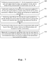
- Fig. 7 an embodiment of the method for adapting a measurement system according to the second aspect of the invention is shown.
- a first step 100 measurement probes 17, 18 of a measurement system are configured to each emit signals shifted in phase and amplitude with the aid of a phase shifting and attenuation or amplification unit 29, 30. It is also conceivable to perform the signal amplitude and phase shift with the aid of standard component of a measurement system such as a base station emulator or a channel emulator.
- each signal comprises a relative delay with the aid of a delay functionality within the phase shifting and attenuator or amplification unit 29, 30. It is also conceivable that said delay functionality is provided within the base station emulator or channel emulator.
- a third step 102 the steps 100 and 101 are performed such that the signal intended for a specific antenna 15, of a device under test 11 is only received at said specific antenna 15 and cancelled out at the remaining antennas 16 of the device under test 11.
- a fourth step 103 the relative delay between each of the measurement probe signals is determined based on the relative distance between the different antenna and measurement probe combinations.
- a fifth step 104 the relative time delay for each of the measurement probe signals is determined empirically by varying the delay time for each measurement probe signal based on the feedback of the measurement result at the antennas of the device under test 11.
- the invention is not limited to the examples and especially not to specific types of devices under test.
- the characteristics of the exemplary embodiments can be used in any advantageous combination.
Landscapes
- Physics & Mathematics (AREA)
- Engineering & Computer Science (AREA)
- Electromagnetism (AREA)
- Computer Networks & Wireless Communication (AREA)
- Signal Processing (AREA)
- Quality & Reliability (AREA)
- General Physics & Mathematics (AREA)
- Spectroscopy & Molecular Physics (AREA)
- Variable-Direction Aerials And Aerial Arrays (AREA)
Abstract
Description
- The invention relates to a measurement system adapted to invert a radio channel for a broadband signal. The system comprises a device under test with at least two antennas, and at least two measurement probes.
To enable the measurement system for measuring broadband signals, the signals of the measurement probes each comprise a relative delay. - In order to increase data throughput multiple-input multiple-output (MIMO) techniques have been developed over the past years. MIMO is a method for multiplying the capacity of a radio link using multiple transmit and receive antennas to exploit multipath propagation. MIMO has become an important element of wireless communication standards. Hence, MIMO over-the-air (OTA) measurement for terminal performance evaluation has become more and more important. MIMO test methods can be divided into two main groups: one based on anechoic chambers and the other based on reverberation chambers. Measurement methods related to anechoic chambers exemplarily include the ring of probes method, the multi-probe method, the two-channel method and the two-stage method. The two-stage method is one of the methods proposed for standard organizations. However, the original proposal for the two-stage method did not support over-the-air (OTA) measurements and thus, radiated interference entering the device under test (DUT) from its transmitter or other sources of noise was not measured.
- Document R4-66AH-0012 presented at the 3GPP Meeting RAN4#66-AH-MIMO-OTA in Munich, Germany, 12-13 March 2013, by Agilent Technologies, Tri-L Solutions with the title "Incorporating self-interference into the two-stage method" is related to an alternative two-stage method that supports over-the-air measurements. The document can be downloaded under the following link: http://www.3gpp.org/ftp/tsg ran/wg4 radio/TSGR4 AHs/TSGR4 66-AH-MIMO-OTA/Docs/. The cited document, hereinafter referred to as R4-66AH-0012 discloses that in a first stage the antenna pattern of the device under test (DUT) is measured. In a second stage, a calibrated radiated connection in an anechoic chamber is provided instead of using a cable connection as known from the original two-stage method. This replacement of the cable connection is achieved by measuring the MIMO propagation conditions in the anechoic chamber between the test system transmit antennas and the device under test (DUT) receive antennas. According to R4-66AH-0012, the inverse of this channel is then applied to the test signals in order to create a transmission channel representing an identity matrix, whereby a high degree of isolation (>20db) is achieved between the transmit and receive antenna pairs as was naturally the case when using cabled connections.
- Even though, the cited document discloses that due to precoding of the transmitted signals it is possible, by calculating the radiated channel matrix and by applying its inverse to the transmitted signals, to create an identity matrix allowing the transmitted signals to be received independently at each antenna, the document is silent regarding the signal properties of the signal to be transmitted, such as bandwidth. Document R4-66AH-0012 does not recognize that beside parameters such as amplitude and phase, additional parameters such as path-loss delay, delay/amplitude/phase of multipath components, frequency-dependency and so on have to be considered when performing channel inversion. Thus, the cited document is silent that with increasing bandwidth the isolation between the transmit- and receive antenna pairs is reduced to values below 20dB. Since bandwidth is anticipated to increase for future communication systems, it is critical to provide a measurement system and method that ensures acceptable isolation parameters even for signals with increasing bandwidths.
- The object of the invention is to provide a measurement system and measurement method, which allow radio channel inversion even for broadband signals.
- The object is solved by the features of the first independent claim for the system and by the features of the second independent claim for the method. Dependent claims contain further developments.
- According to a first aspect of the invention, a measurement system is adapted to invert a radio channel for a broadband signal comprising a device under test with at least two antennas and comprising at least two measurement probes is provided. Said measurement probes are configured to each emit signals shifted in phase and amplitude. The signals emitted by the measurement probes are configured such that each of the signals comprises a relative delay. Advantageously, additionally to the use of complex amplitude (i.e. amplitude and phase) in order to invert the radio channel (i.e. separate the signals determined for each device under test receive antenna) the parameter of delay is used.
- According to a first preferred implementation form of the first aspect, the signals emitted by the measurement probes are shifted in phase and amplitude and are delayed such that the signal intended for a specific antenna of the device under test is only received at said specific antenna and cancelled out at the remaining antennas of the device under test. Advantageously, the use of the delay as additional parameter to phase and amplitude shifting allows increasing the destructive interference (i.e. isolation) significantly. Especially for higher bandwidths the time delay is necessary to ensure that each antenna of the device under test only receives the desired signals and no other signals that negatively affect the measurement results. Thus, the additional time delay, especially for broadband signals, allows a destructive interference of unwanted signals at each antenna and ensures only the desired signals are received, respectively measured at the specific antenna.
- According to a second preferred implementation form of the first aspect, the delay is determined based on the relative distance between the different antenna and measurement probe combinations. Advantageously, the channel inversion of a physical radio channel between antennas of a device under test that shall receive signals (DUT receive antennas) from a measurement probe (probe antennas) is possible even for high bandwidth signals by adding a relative time delay to each signal emitted by the probe antennas, wherein the time delay takes into account the various distances between the different antenna and probe combinations and is therefore suitable to be used for various test setups with different device under test antenna locations and different measurement probe locations.
- According to a further preferred implementation form of the first aspect, the delay is in the range of 0 to 0.5ns.
- According to a further preferred implementation form of the first aspect, at least the measurement probes and the device under test are located within an anechoic chamber. Advantageously, the anechoic chamber prevents disturbances from external influences and ensures reproducibility of measurements.
- According to a further preferred implementation form of the first aspect, the number of delayed signals of each one of the measurement probes can be varied.
- According to a further preferred implementation form of the first aspect, the number of delayed signals is increased until a predefined signal compensation is reached. Advantageously, increasing the number of delayed signals reduces the amplitude of an unwanted remaining signal. Said remaining signal is called a residual component. With each further delayed signal, the amplitude of the residual component is reduced. A predefined signal compensation is determined by the defined allowable residual component. If the defined residual component is not small enough, a further delayed signal has to be emitted.
- According to a further preferred implementation form of the first aspect, the number of delayed signals depends on the spatial arrangement between the antennas of the device under test and the measurement probes.
- According to a further preferred implementation form of the first aspect, the measurement system comprises a base station emulator and/or a channel emulator, wherein the channel emulator configures the measurement probes each have a relative time delay. Advantageously, using a base station and channel emulator, which are frequently used in standard setups for performance testing of communication devices, especially for devices for multiple-input multiple-output (MIMO) applications, allows the channel inversion of the physical radio channel between the DUT receive antenna and the probe antennas for signals with higher bandwidth in an easy and cost-effective way. This is just by adapting the channel emulator to generate a relative time delay between signals of the measurement probes. It is also conceivable that the base station emulator triggers the time delay.
- According to a further preferred implementation form of the first aspect, the signals are generated by a signal generator connected to a splitter distributing the signal to the measurement probes. At least one measurement probe is connected to a phase shifting unit and an attenuator or amplifier unit and to a signal delay unit to configure the signals emitted by the measurement probe.
- According to a second aspect of the invention, a method for adapting a measurement system to invert a radio channel for a broadband signal is provided. The method comprises the step of configuring measurement probes of a measurement system to each emit signals shifted in phase and amplitude with the aid of a phase shifting and attenuation or amplification unit. The method further comprises the step of configuring the signals of the measurement probes such that each signal comprises a relative delay. It is also conceivable that the phase and amplitude shifting functionality and the time delay functionality are implemented within a base station emulation unit or within as channel emulator unit.
- According to a first preferred implementation form of the second aspect, the method further comprises the step of shifting the signals emitted by the measurement probes in phase and amplitude, and delaying the signals emitted by the measurement probes relative to each other such that the signal intended for a specific antenna of a device under test is only received at said specific antenna and cancelled out at the remaining antennas of the device under test.
- According to a further preferred implementation form of the second aspect, the method further comprises the step of determining the delay between each of the measurement probe signals based on the relative distance between the different antenna and measurement probe combinations.
- Alternatively or additionally, it is further conceivable that the relative time delay for each of the measurement probe signals is determined empirically by varying the delay time for each measurement probe signal based on the feedback of the measurement result at the antennas of the device under test. Advantageously, since in most cases the antenna configuration of a device under test is not exactly known, the determination of the relative delay time of the measurement probe signals is determined based on measurement results at each device under test antenna. Such measurement indicated for the delay time can be the measurement of the power of the signal that shall be received by the device under test antenna, a bit error rate (BER) measurement of the device under test or any other suitable measurement. When the measurement results are not acceptable, the time delay is varied and the measurement is repeated until a desired measurement result is achieved.
- According to a further preferred implementation form of the second aspect, the method further comprises the step of determining a delay in the range of 0 to 0.5ns.
- According to a further preferred implementation form of the second aspect, the method further comprises the step of increasing the number of delayed signals until a predefined signal compensation is reached.
- Exemplary embodiments of the invention are now further explained with regard to the drawings by way of example only and not for limitation. In the drawings
- Fig. 1
- shows an embodiment of a radiated-two-stage test setup;
- Fig. 2
- shows an embodiment of the measurement system according to the first aspect of the invention;
- Fig. 3
- shows an embodiment of time delayed signals emitted from measurement probes to reduce residual components at antennas of the device under test (DUT antennas);
- Fig. 4
- shows an embodiment of a simulation of maximum achievable isolation by changing the phase of one probe antenna and for a small signal bandwidth based on the measurement setup depicted in
Fig. 2 ; - Fig. 5
- shows an embodiment of a simulation of maximum achievable isolation by changing the phase of one probe antenna and for a medium signal bandwidth based on the measurement setup depicted in
Fig. 2 ; - Fig. 6
- shows an embodiment of a simulation of maximum achievable isolation by changing the phase of one probe antenna and for a large signal bandwidth based on the measurement setup depicted in
Fig. 2 ; and - Fig. 7
- shows an embodiment of the measurement method according to the second aspect of the invention.
- In
Fig. 1 , an embodiment of a radiated two-stage (RTS) test setup is shown. The radiated two-stage method (RTS) measures both, the patterns of the device under test (DUT) and the multiple-input multiple-output (MIMO) throughput performance. The setup includes twomeasurement probes antennas test 11 and the measurement probes 17, 18 are located within ananechoic chamber 21. The twoprobe antennas anechoic chamber 21. Due to the propagation channel between the measurement probes 17, 18 and theantennas test 11, signals transmitted from eachprobe antenna antenna user equipment 11. - The measurement probes 17, 18 are connected to a channel emulator (CE) 26, which is further connected to a base station emulator (BSE) 27. The device under
test 11 is additionally connected for example via a cable connection or a wireless connection to the base station emulator (BSE) 27. The signals generated by the base station emulator (BSE) 27 are modified by the channel emulator (CE) 26 according to a predefined channel model, in order to simulate real-word conditions. With the aid of the base station emulator (BSE) 27 and the channel emulator (CE) 26 performance testing of the device undertest 11 according to various test standards can be conducted. The connection from the device undertests 11 to thebase station emulator 27 allows to modify the setting of thebase station emulator 27 based on measurements performed by the device undertest 11. - Thus, it is critical to isolate the signals from each other in the second stage of the two-stage measurement to be able to perform an accurate measurement.
- In a first stage, the antenna pattern of the antennas of the device under test is measured with the test setup.
- In a second stage, the transmitted signals are precoded using spatial multiplexing techniques and using results of the antenna pattern measurement, which allows to calculate the radiated channel matrix and to apply the inverse of said radiated channel matrix to the transmitted signals. By doing so, an identity matrix is created allowing the transmitted signals to be received independently at each antenna.
- In
Fig. 2 , an embodiment of themeasurement system 20 according to the first aspect of the invention is shown.Fig. 2 shows the device under test (DUT) 11 including twoantennas Fig. 2 , the twoantennas signal generator 28 that is connected to asignal splitter 31 that equally splits the input signal from thesignal generator 28 in two output signals. The outputs of thesignal splitter 31, are each connected to asignal condition unit signal condition units measurement probe 17 and ameasurement probe 18. The measurement probes 17, 18 are also called measurement antennas or probe antennas and are preferably located on the opposite walls of an anechoic chamber (not shown). - Is also possible to just provide one
signal condition unit 29. However, in order to explain the signal delay concept inFig. 3 , twosignal condition units signal condition unit signal condition unit signal generator 28 preferably generates broadband signals, preferably higher than for example 100MHz. - In
Fig. 3 , the concept of delaying signals emitted by the measurement probes 17, 18 and the received signals at eachantenna Fig. 2 . -
Fig. 3 shows a data stream A, emitted by themeasurement probe 17 and a data stream B, emitted by themeasurement probe 18. Data stream A shall be received only by theantenna 15 of the device undertest 11, in other words, data stream A shall only be measured atantenna 15. Data stream B shall be received only by theantenna 16 of the device undertest 11, in other words, data stream B shall only be measured atantenna 16. - However, since data stream A travels across the device under test and also passes
antenna 16 of the device undertest 11,antenna 16 receives a fraction of data stream A, named A', after a time delay Δτ depending on the distance d betweenantennas test 11, as depicted inFig. 2 . Analogously,antenna 15 of the device undertest 11, receives a fraction of data stream B, named B', after a time delay Δτ depending on the distance d as depicted inFig. 2 . - The fraction of data stream B received at
antenna 15 is depicted by a block named B' and the fraction of data stream A received atantenna 16 is depicted by a block named A'. The fraction of data stream A, named A' and the fraction of data stream B, named B' are delayed with respect to their originating data streams A and B by a value Δτ. - Without any further compensation measures, in other words without any further delayed signal,
antenna 15 would receive and measure a data stream A and additionally a fraction of a data stream B, named data stream B' having the same orientation as B, but with a reduced amplitude and a time delay Δτ with respect to data stream B. - This analogously applies for
antenna 16, which would receive and measure a data stream B and additionally a fraction of a data stream A, named data stream A' having the same orientation as A, but with a reduced amplitude and a time delay Δτ with respect to data stream A. - Data stream B' received at
antenna 15 and data stream A' received atantenna 16 are called residual components in case no further data stream is emitted bymeasurement probe measurement probes - In this embodiment,
measurement probe 17 emits a data stream B1, having a time delay Δτ with respect to data stream A. This is a first delayed signal emitted bymeasurement probe 17. Said delay depends on the distance d betweenantenna test 11. Data stream B1 has the same amplitude than data stream B' but an opposite orientation, in other words the data stream B1 emitted bymeasurement probe 17 is phase shifted according to 180° or π. - Since data stream B1 is delayed by Δτ, data stream B1 and data stream B' are received by
antenna 15 of the device undertest 11 at the same time. Since said data stream B1 and data stream B' further have the same amplitude and opposite orientation destructive interference is taking place and B' and B1 are cancelled out atantenna 15. This analogously applies forantenna 16, where data stream A1 and data stream A' interfere with each other and any component of data stream A' and A1 is cancelled out atantenna 16. - However, a fraction of data stream A1, named A1', emitted by
measurement probe 18 to compensate for data stream A', is received atantenna 15 having a time delay Δτ with respect to the data stream A1, having a reduced amplitude compared to A1 and having the same orientation as data stream A1. In order to compensate for said data stream A1',measurement probe 17 emits a data stream A2. This is a second delayed signal emitted bymeasurement probe 17. Said data stream A2 has opposite orientation with respect to A1', but the same amplitude than data stream A1'. Furthermore, data stream A2 has a delay Δτ with respect to data stream B1. - Since data stream A2 is delayed by Δτ, data stream A1' and data stream A2 are received by
antenna 15 of the device undertest 11 at the same time. Since said data stream A2 and data stream A1' further have the same amplitude and opposite orientation, destructive interference is taking place and A1' and A2 are cancelled out atantenna 15. This analogously applies forantenna 16, where data stream B2 and data stream B1' interfere with each other and any component of data stream B1' and B2 is cancelled out atantenna 16. - Finally, according to the embodiment shown in
Fig. 3 , no additional data stream is emitted bymeasurement probe measurement probes Fig. 2 . - A fraction of data stream B2 emitted by
measurement probe 18 is received atantenna 15 having a reduced amplitude compared to data stream B2 and having a delay Δτ with respect to data stream B2. Since no further compensation signal is emitted bymeasurement probe 17, the remaining data stream is called residual component B2'. Analogously, a fraction of data stream A2 is received atantenna 16 having a reduced amplitude compared to data stream A2 and having a delay Δτ with respect to data stream A2. Since no further compensation signal is emitted bymeasurement probe 18, the remaining data stream is called residual component A2'. - It is obvious from
Fig. 3 that with each further delayed signal emitted bymeasurement probes -
Fig. 4 to 6 show an embodiment of a simulation of maximum achievable isolation by changing the phase of one probe antenna and for different signal bandwidths based on the measurement setup depicted inFig. 2 . -
Figs. 4 to 6 show a simulation result forantenna 15 of device undertest 11. Due to symmetry in the simulation setup according toFig. 2 , the results forantenna 16 of device undertest 11 are equivalent. In order to investigate maximum achievable isolation, the phase ofprobe antenna 18 is changed between 0 and 2π (2pi). Since path loss is not simulated in this setup, the signals originating fromprobe reach antenna 15 of the device undertest 11 with the same power. The simulation results show the remaining power after summation of the two signals in relation to the relative phase shift ofprobe antenna 18. The distance d between the twoantennas test 11 is 15cm in this example. - As shown in
Fig. 2 theprobe antennas Fig. 2 represents the worst case assumption (maximum delay). No reflections are simulated, thus a fully anechoic chamber is assumed. Furthermore, path loss betweenantenna test 11 is ignored, i.e.probe 17 andprobe 18 are far away from the device undertest 11. -
Fig. 4 shows a simulation result for a small signal bandwidth of 1.4MHz. At a phase shift of approx. 3,14 radian (Pi), which equals a phase shift of 180°, the remaining power is very small. As can be seen inFig. 4 the relative power in dB is -50dB. In other words signals with a bandwidth up to 1.4MHz show a clear effect of destructive interference at a phase shift of 180° respectively 3,14 radian (Pi), which means that high isolation values are achievable for signals with such a bandwidth. -
Fig. 5 shows a simulation result for a medium signal bandwidth of 100MHz. At a phase shift of approx. 3,14 radian (Pi), which equals a phase shift of 180°, the remaining power is still small. As can be seen inFig. 5 the relative power in dB is -27dB. In other words signals with a bandwidth up to 100MHz show a clear effect of destructive interference at a phase shift of 180° respectively 3,14 radian (Pi), which means that high isolation values are achievable for signals with such a bandwidth. -
Fig. 6 shows a simulation result for a relatively high signal bandwidth of 400Hz. At a phase shift of approx. 3,14 radian (Pi), which equals a phase shift of 180°, the remaining relative power in dB is -15dB, which clearly shows that the maximum achievable isolation is reduced. - The simulation results of
Figs. 4 to 6 show that increasing the bandwidth of the simulated signal results in a decreased maximum achievable isolation when only optimizing phase (and power). The simulations inFig. 4 to 6 show that according to finding of the present invention there clearly is a need for a system and method that allows channel inversion for higher bandwidths. According to the simulation results, higher bandwidths are bandwidths above 100MHz. - In
Fig. 7 , an embodiment of the method for adapting a measurement system according to the second aspect of the invention is shown. In afirst step 100 measurement probes 17, 18 of a measurement system are configured to each emit signals shifted in phase and amplitude with the aid of a phase shifting and attenuation oramplification unit - In a
second step 101 the signals of the measurement probes 17, 18, in other words the signals to be emitted by the measurement probes, are configured such that each signal comprises a relative delay with the aid of a delay functionality within the phase shifting and attenuator oramplification unit - In a
third step 102 thesteps specific antenna 15, of a device undertest 11 is only received at saidspecific antenna 15 and cancelled out at the remainingantennas 16 of the device undertest 11. - In a
fourth step 103 the relative delay between each of the measurement probe signals is determined based on the relative distance between the different antenna and measurement probe combinations. - Finally, in a
fifth step 104 the relative time delay for each of the measurement probe signals is determined empirically by varying the delay time for each measurement probe signal based on the feedback of the measurement result at the antennas of the device undertest 11. - The invention is not limited to the examples and especially not to specific types of devices under test. The characteristics of the exemplary embodiments can be used in any advantageous combination.
- While various embodiments of the present invention have been described above, it should be understood that they have been presented by way of example only, and not limitation. Numerous changes to the disclosed embodiments can be made in accordance with the disclosure herein without departing from the spirit or scope of the invention. Thus, the breadth and scope of the present invention should not be limited by any of the above described embodiments. Rather, the scope of the invention should be defined in accordance with the following claims and their equivalents.
- Although the invention has been illustrated and described with respect to one or more implementations, equivalent alterations and modifications will occur to others skilled in the art upon the reading and understanding of this specification and the annexed drawings. In addition, while a particular feature of the invention may have been disclosed with respect to only one of several implementations, such feature may be combined with one or more other features of the other implementations as may be desired and advantageous for any given or particular application.
Claims (15)
- A measurement system (20) adapted to invert a radio channel for a broadband signal, the system comprising:- a device under test (11) with at least two antennas (15, 16), and- at least two measurement probes (17, 18),wherein said measurement probes (17, 18) are configured to each emit signals shifted in phase and amplitude, and wherein the signals of the measurement probes (17, 18) each comprise a relative delay.
- The system according to claim 1,
wherein the signals emitted by the measurement probes (17, 18) are shifted in phase and amplitude and are delayed such that the signal intended for a specific antenna (15) of the device under test (11) is only received at said specific antenna (15) and cancelled out at the remaining antennas (16) of the device under test (11). - The system according to claim 1 or 2,
wherein the delay is determined based on the relative distance between the different antenna (15, 16) and measurement probe (17, 18) combinations. - The system according to any of claims 1 to 3,
wherein the delay is in the range of 0 to 0.5ns. - The system according to any of claims 1 to 4,
wherein at least the measurement probes (17, 18) and the device under test (11) are located within an anechoic chamber (21). - The system according to any of claims 1 to 5,
wherein the number of delayed signals of each one of the measurement probes (17, 18) can be varied. - The system according to claims 6,
wherein the number of delayed signals is increased until a predefined signal compensation is reached. - The system according to claim 6,
wherein the number of delayed signals depends on the spatial arrangement between the antennas (15, 16) of the device under test (11) and the measurement probes (17, 18) . - The system according to any of claims 1 to 8,
wherein the measurement system comprises a base station emulator (27) and/or a channel emulator (26), wherein the channel emulator (26) configures the measurement probes (17, 18) each having a relative time delay. - The system according to any of claims 1 to 8,
wherein the signals are generated by a signal generator (28) connected to a splitter (31) distributing the signal to the measurement probes (17, 18), and/or
wherein at least one measurement probe (17, 18) is connected to a phase shifting unit (29) and an attenuator or amplifier unit (29) and to a signal delay unit (29) to configure the signals emitted by the measurement probe (17, 18). - A method for adapting a measurement system to invert a radio channel for a broadband signal, the method comprising the steps of:configuring measurement probes (17, 18) of a measurement system to each emit signals shifted in phase and amplitude with the aid of a phase shifting and attenuation or amplification unit (29, 30), andconfiguring the signals of the measurement probes (17, 18) that each signal comprises a relative delay.
- The method according to claim 11,
wherein the method further comprises the step of shifting the signals emitted by the measurement probes (17, 18) in phase and amplitude, and
delaying the signals emitted by the measurement probes relative to each other such that the signal intended for a specific antenna of a device under test is only received at said specific antenna and cancelled out at the remaining antennas of the device under test. - The method according to claim 11 or 12,
wherein the method further comprises the step of determining the delay between each of the measurement probe signals based on the relative distance between the different antenna and measurement probe combinations. - The method according to any of claims 11 to 13, wherein the method further comprises the step of determining a delay in the range of 0 to 0.5ns.
- The method according to any of claims 11 to 14, wherein the method further comprises the step of increasing the number of delayed signals until a predefined signal compensation is reached.
Priority Applications (3)
| Application Number | Priority Date | Filing Date | Title |
|---|---|---|---|
| EP18170041.0A EP3565135B8 (en) | 2018-04-30 | 2018-04-30 | System and method for inverting a radio channel for broadband signals |
| US16/159,459 US20190334637A1 (en) | 2018-04-30 | 2018-10-12 | System and method for inverting a radio channel for broadband signals |
| CN201811624078.5A CN110430002B (en) | 2018-04-30 | 2018-12-28 | System and method for inverting radio channel for wideband signal |
Applications Claiming Priority (1)
| Application Number | Priority Date | Filing Date | Title |
|---|---|---|---|
| EP18170041.0A EP3565135B8 (en) | 2018-04-30 | 2018-04-30 | System and method for inverting a radio channel for broadband signals |
Publications (3)
| Publication Number | Publication Date |
|---|---|
| EP3565135A1 true EP3565135A1 (en) | 2019-11-06 |
| EP3565135B1 EP3565135B1 (en) | 2022-04-27 |
| EP3565135B8 EP3565135B8 (en) | 2022-06-22 |
Family
ID=62091737
Family Applications (1)
| Application Number | Title | Priority Date | Filing Date |
|---|---|---|---|
| EP18170041.0A Active EP3565135B8 (en) | 2018-04-30 | 2018-04-30 | System and method for inverting a radio channel for broadband signals |
Country Status (3)
| Country | Link |
|---|---|
| US (1) | US20190334637A1 (en) |
| EP (1) | EP3565135B8 (en) |
| CN (1) | CN110430002B (en) |
Cited By (1)
| Publication number | Priority date | Publication date | Assignee | Title |
|---|---|---|---|---|
| EP3993287A1 (en) | 2020-10-30 | 2022-05-04 | Rohde & Schwarz GmbH & Co. KG | Method for determining a pre-equalization matrix and test setup |
Families Citing this family (3)
| Publication number | Priority date | Publication date | Assignee | Title |
|---|---|---|---|---|
| US11381325B1 (en) * | 2021-01-21 | 2022-07-05 | Rohde & Schwarz Gmbh & Co. Kg | Method and system for determining an optimum position of a device under test |
| US12081460B2 (en) * | 2022-05-27 | 2024-09-03 | Corning Research & Development Corporation | Out-of-order data packet processing in a wireless communications system (WCS) |
| CN119483778A (en) * | 2023-08-11 | 2025-02-18 | 诺基亚技术有限公司 | Virtual Cable Calibration for Over-the-Air Conformance Testing |
Citations (8)
| Publication number | Priority date | Publication date | Assignee | Title |
|---|---|---|---|---|
| US20060009185A1 (en) * | 2004-07-08 | 2006-01-12 | Khosro Shamsaifar | Method and apparatus capable of interference cancellation |
| US20110200084A1 (en) * | 2010-02-18 | 2011-08-18 | John Robert Griesing | Testing performance of a wireless device |
| EP2432073A1 (en) * | 2009-05-12 | 2012-03-21 | Panasonic Corporation | Antenna evaluating apparatus and antenna evaluation method |
| US8526550B1 (en) * | 2009-03-18 | 2013-09-03 | Lockheed Martin Corporation | System and method for wideband interference suppression |
| US20140218240A1 (en) * | 2013-02-07 | 2014-08-07 | L-3 Communications Corporation | Interfeinterfence cancellation system for location and direction finding |
| WO2014197185A1 (en) * | 2013-06-07 | 2014-12-11 | Litepoint Corporation | System and method for testing radio frequency wireless signal transceivers using wireless test signals |
| EP3054743A1 (en) * | 2013-11-08 | 2016-08-10 | Huawei Technologies Co., Ltd. | Single board, wireless communication system and calibration method for channel inside/outside single board |
| EP3293897A1 (en) * | 2016-09-12 | 2018-03-14 | Rohde & Schwarz GmbH & Co. KG | System and method for characterization of multi-element antenna |
Family Cites Families (10)
| Publication number | Priority date | Publication date | Assignee | Title |
|---|---|---|---|---|
| DE4303355A1 (en) * | 1993-02-05 | 1994-08-11 | Philips Patentverwaltung | Radio system |
| US7702295B1 (en) * | 2006-12-22 | 2010-04-20 | Nortel Networks Limited | Frequency agile duplex filter |
| CN103078688B (en) * | 2012-12-28 | 2014-12-31 | 中国电子科技集团公司第五十四研究所 | Method for calibrating delay inconsistency of radio star signal and spacecraft signal in interferometry |
| WO2015042336A1 (en) * | 2013-09-19 | 2015-03-26 | Kannan Srinivasan | Radio with flexible degrees of freedom provision for transmit and receive rf chains |
| US9246607B2 (en) * | 2014-02-10 | 2016-01-26 | Spirent Communications, Inc. | Automatic phase calibration |
| WO2017144087A1 (en) * | 2016-02-23 | 2017-08-31 | Advantest Corporation | Method and device for calibrating an automated test equipment |
| US9705611B1 (en) * | 2016-03-24 | 2017-07-11 | Rockwell Collins, Inc. | Systems and methods for array antenna calibration |
| US10637590B2 (en) * | 2016-08-12 | 2020-04-28 | Apple Inc. | Millimeter wave test systems |
| CN108574539B (en) * | 2017-03-08 | 2021-01-15 | 深圳市通用测试系统有限公司 | Signal generation method and device based on MIMO wireless terminal test |
| CN107576944A (en) * | 2017-08-15 | 2018-01-12 | 成都普诺科技有限公司 | Change radiofrequency signal delay time remote analog system |
-
2018
- 2018-04-30 EP EP18170041.0A patent/EP3565135B8/en active Active
- 2018-10-12 US US16/159,459 patent/US20190334637A1/en not_active Abandoned
- 2018-12-28 CN CN201811624078.5A patent/CN110430002B/en active Active
Patent Citations (8)
| Publication number | Priority date | Publication date | Assignee | Title |
|---|---|---|---|---|
| US20060009185A1 (en) * | 2004-07-08 | 2006-01-12 | Khosro Shamsaifar | Method and apparatus capable of interference cancellation |
| US8526550B1 (en) * | 2009-03-18 | 2013-09-03 | Lockheed Martin Corporation | System and method for wideband interference suppression |
| EP2432073A1 (en) * | 2009-05-12 | 2012-03-21 | Panasonic Corporation | Antenna evaluating apparatus and antenna evaluation method |
| US20110200084A1 (en) * | 2010-02-18 | 2011-08-18 | John Robert Griesing | Testing performance of a wireless device |
| US20140218240A1 (en) * | 2013-02-07 | 2014-08-07 | L-3 Communications Corporation | Interfeinterfence cancellation system for location and direction finding |
| WO2014197185A1 (en) * | 2013-06-07 | 2014-12-11 | Litepoint Corporation | System and method for testing radio frequency wireless signal transceivers using wireless test signals |
| EP3054743A1 (en) * | 2013-11-08 | 2016-08-10 | Huawei Technologies Co., Ltd. | Single board, wireless communication system and calibration method for channel inside/outside single board |
| EP3293897A1 (en) * | 2016-09-12 | 2018-03-14 | Rohde & Schwarz GmbH & Co. KG | System and method for characterization of multi-element antenna |
Non-Patent Citations (2)
| Title |
|---|
| "3GPP Meeting RAN4#66-AH-MIMO-OTA", 12 March 2013, AGILENT TECHNOLOGIES |
| YA JING ET AL: "MIMO OTA Testing Based on Transmit Signal Processing", IEEE INSTRUMENTATION & MEASUREMENT MAGAZINE, 1 June 2016 (2016-06-01), pages 43 - 50, XP055521500, Retrieved from the Internet <URL:https://ieeexplore.ieee.org/stamp/stamp.jsp?tp=&arnumber=7477954> [retrieved on 20181106] * |
Cited By (3)
| Publication number | Priority date | Publication date | Assignee | Title |
|---|---|---|---|---|
| EP3993287A1 (en) | 2020-10-30 | 2022-05-04 | Rohde & Schwarz GmbH & Co. KG | Method for determining a pre-equalization matrix and test setup |
| CN114448480A (en) * | 2020-10-30 | 2022-05-06 | 罗德施瓦兹两合股份有限公司 | Method and test device for determining a pre-equalization matrix |
| US11996898B2 (en) | 2020-10-30 | 2024-05-28 | Rohde & Schwarz Gmbh & Co. Kg | Method for determining a pre-equalization matrix and test setup |
Also Published As
| Publication number | Publication date |
|---|---|
| US20190334637A1 (en) | 2019-10-31 |
| EP3565135B8 (en) | 2022-06-22 |
| CN110430002B (en) | 2022-09-02 |
| EP3565135B1 (en) | 2022-04-27 |
| CN110430002A (en) | 2019-11-08 |
Similar Documents
| Publication | Publication Date | Title |
|---|---|---|
| US11668740B2 (en) | Over the air calibration and testing of beamforming-based multi-antenna devices in anechoic and non-anechoic environments | |
| JP6886984B2 (en) | Wireless performance test method for MIMO wireless terminals | |
| US12013424B2 (en) | Antenna test system and a method for testing an antenna | |
| US10649023B2 (en) | Radio test system and method for testing a device under test | |
| JP5307249B2 (en) | Method and apparatus for inspecting mobile radio device by static channel simulation | |
| EP3565135B1 (en) | System and method for inverting a radio channel for broadband signals | |
| EP3993287B1 (en) | Method for determining a pre-equalization matrix and test setup | |
| Konishi et al. | Channel sounding technique using MIMO software radio architecture | |
| US20240348318A1 (en) | Method and apparatus for testing disaggregated components of a radio access network | |
| Zhang et al. | Dynamic sub-THZ radio channel emulation: Principle, challenges, and experimental validation | |
| US11451312B2 (en) | Mobile-assisted phase calibration method and system | |
| EP3631478A1 (en) | Apparatuses, methods and a measurement system for characterizing a wireless communication component usable in non-anechoic environments | |
| US11381325B1 (en) | Method and system for determining an optimum position of a device under test | |
| CN116112101B (en) | Air radiation test system, method and tester for wireless equipment | |
| Guo et al. | Over the air MIMO channel model validation | |
| Mei et al. | OTA throughput prediction of MIMO antennas for wireless devices by simulated realistic channel model | |
| US20240275501A1 (en) | A radio network distribution board | |
| Jing et al. | Radiated two-stage MIMO OTA test method progress for antenna performance evaluation | |
| Fielitz et al. | On how to measure the interference of multiple wireless transmission systems using a well defined environment | |
| US20260128803A1 (en) | Calibrating amplitude and phase of a transceiver array in a network test device | |
| Lorenz et al. | On modeling OTA channel emulation systems | |
| US20170093534A1 (en) | Circuit for introducing signal jitter | |
| Liu et al. | An improved relative channel reciprocity calibration method in TDD massive MIMO systems | |
| Yan et al. | A Novel Channel Reconstruction Method for Multiuser Over-the-Air Testing | |
| Fan et al. | Emulating Realistic Bidirectional Spatial Channels for MIMO OTA Testing |
Legal Events
| Date | Code | Title | Description |
|---|---|---|---|
| STAA | Information on the status of an ep patent application or granted ep patent |
Free format text: STATUS: EXAMINATION IS IN PROGRESS |
|
| PUAI | Public reference made under article 153(3) epc to a published international application that has entered the european phase |
Free format text: ORIGINAL CODE: 0009012 |
|
| 17P | Request for examination filed |
Effective date: 20181211 |
|
| AK | Designated contracting states |
Kind code of ref document: A1 Designated state(s): AL AT BE BG CH CY CZ DE DK EE ES FI FR GB GR HR HU IE IS IT LI LT LU LV MC MK MT NL NO PL PT RO RS SE SI SK SM TR |
|
| AX | Request for extension of the european patent |
Extension state: BA ME |
|
| GRAP | Despatch of communication of intention to grant a patent |
Free format text: ORIGINAL CODE: EPIDOSNIGR1 |
|
| STAA | Information on the status of an ep patent application or granted ep patent |
Free format text: STATUS: GRANT OF PATENT IS INTENDED |
|
| GRAS | Grant fee paid |
Free format text: ORIGINAL CODE: EPIDOSNIGR3 |
|
| INTG | Intention to grant announced |
Effective date: 20220218 |
|
| GRAA | (expected) grant |
Free format text: ORIGINAL CODE: 0009210 |
|
| STAA | Information on the status of an ep patent application or granted ep patent |
Free format text: STATUS: THE PATENT HAS BEEN GRANTED |
|
| AK | Designated contracting states |
Kind code of ref document: B1 Designated state(s): AL AT BE BG CH CY CZ DE DK EE ES FI FR GB GR HR HU IE IS IT LI LT LU LV MC MK MT NL NO PL PT RO RS SE SI SK SM TR |
|
| REG | Reference to a national code |
Ref country code: GB Ref legal event code: FG4D |
|
| REG | Reference to a national code |
Ref country code: CH Ref legal event code: EP |
|
| REG | Reference to a national code |
Ref country code: AT Ref legal event code: REF Ref document number: 1487779 Country of ref document: AT Kind code of ref document: T Effective date: 20220515 |
|
| RBV | Designated contracting states (corrected) |
Designated state(s): AL AT BE BG CY CZ DE DK EE ES FI FR GB GR HR HU IS IT LT LU LV MC MK MT NL NO PL PT RO RS SE SI SK SM TR |
|
| REG | Reference to a national code |
Ref country code: DE Ref legal event code: R096 Ref document number: 602018034397 Country of ref document: DE |
|
| REG | Reference to a national code |
Ref country code: IE Ref legal event code: FG4D |
|
| REG | Reference to a national code |
Ref country code: LT Ref legal event code: MG9D |
|
| REG | Reference to a national code |
Ref country code: NL Ref legal event code: MP Effective date: 20220427 |
|
| REG | Reference to a national code |
Ref country code: AT Ref legal event code: MK05 Ref document number: 1487779 Country of ref document: AT Kind code of ref document: T Effective date: 20220427 |
|
| PG25 | Lapsed in a contracting state [announced via postgrant information from national office to epo] |
Ref country code: NL Free format text: LAPSE BECAUSE OF FAILURE TO SUBMIT A TRANSLATION OF THE DESCRIPTION OR TO PAY THE FEE WITHIN THE PRESCRIBED TIME-LIMIT Effective date: 20220427 |
|
| PG25 | Lapsed in a contracting state [announced via postgrant information from national office to epo] |
Ref country code: SE Free format text: LAPSE BECAUSE OF FAILURE TO SUBMIT A TRANSLATION OF THE DESCRIPTION OR TO PAY THE FEE WITHIN THE PRESCRIBED TIME-LIMIT Effective date: 20220427 Ref country code: PT Free format text: LAPSE BECAUSE OF FAILURE TO SUBMIT A TRANSLATION OF THE DESCRIPTION OR TO PAY THE FEE WITHIN THE PRESCRIBED TIME-LIMIT Effective date: 20220829 Ref country code: NO Free format text: LAPSE BECAUSE OF FAILURE TO SUBMIT A TRANSLATION OF THE DESCRIPTION OR TO PAY THE FEE WITHIN THE PRESCRIBED TIME-LIMIT Effective date: 20220727 Ref country code: LT Free format text: LAPSE BECAUSE OF FAILURE TO SUBMIT A TRANSLATION OF THE DESCRIPTION OR TO PAY THE FEE WITHIN THE PRESCRIBED TIME-LIMIT Effective date: 20220427 Ref country code: HR Free format text: LAPSE BECAUSE OF FAILURE TO SUBMIT A TRANSLATION OF THE DESCRIPTION OR TO PAY THE FEE WITHIN THE PRESCRIBED TIME-LIMIT Effective date: 20220427 Ref country code: GR Free format text: LAPSE BECAUSE OF FAILURE TO SUBMIT A TRANSLATION OF THE DESCRIPTION OR TO PAY THE FEE WITHIN THE PRESCRIBED TIME-LIMIT Effective date: 20220728 Ref country code: FI Free format text: LAPSE BECAUSE OF FAILURE TO SUBMIT A TRANSLATION OF THE DESCRIPTION OR TO PAY THE FEE WITHIN THE PRESCRIBED TIME-LIMIT Effective date: 20220427 Ref country code: ES Free format text: LAPSE BECAUSE OF FAILURE TO SUBMIT A TRANSLATION OF THE DESCRIPTION OR TO PAY THE FEE WITHIN THE PRESCRIBED TIME-LIMIT Effective date: 20220427 Ref country code: BG Free format text: LAPSE BECAUSE OF FAILURE TO SUBMIT A TRANSLATION OF THE DESCRIPTION OR TO PAY THE FEE WITHIN THE PRESCRIBED TIME-LIMIT Effective date: 20220727 Ref country code: AT Free format text: LAPSE BECAUSE OF FAILURE TO SUBMIT A TRANSLATION OF THE DESCRIPTION OR TO PAY THE FEE WITHIN THE PRESCRIBED TIME-LIMIT Effective date: 20220427 |
|
| PG25 | Lapsed in a contracting state [announced via postgrant information from national office to epo] |
Ref country code: RS Free format text: LAPSE BECAUSE OF FAILURE TO SUBMIT A TRANSLATION OF THE DESCRIPTION OR TO PAY THE FEE WITHIN THE PRESCRIBED TIME-LIMIT Effective date: 20220427 Ref country code: PL Free format text: LAPSE BECAUSE OF FAILURE TO SUBMIT A TRANSLATION OF THE DESCRIPTION OR TO PAY THE FEE WITHIN THE PRESCRIBED TIME-LIMIT Effective date: 20220427 Ref country code: LV Free format text: LAPSE BECAUSE OF FAILURE TO SUBMIT A TRANSLATION OF THE DESCRIPTION OR TO PAY THE FEE WITHIN THE PRESCRIBED TIME-LIMIT Effective date: 20220427 Ref country code: IS Free format text: LAPSE BECAUSE OF FAILURE TO SUBMIT A TRANSLATION OF THE DESCRIPTION OR TO PAY THE FEE WITHIN THE PRESCRIBED TIME-LIMIT Effective date: 20220827 |
|
| REG | Reference to a national code |
Ref country code: CH Ref legal event code: PL |
|
| REG | Reference to a national code |
Ref country code: BE Ref legal event code: MM Effective date: 20220430 |
|
| REG | Reference to a national code |
Ref country code: DE Ref legal event code: R097 Ref document number: 602018034397 Country of ref document: DE |
|
| PG25 | Lapsed in a contracting state [announced via postgrant information from national office to epo] |
Ref country code: SM Free format text: LAPSE BECAUSE OF FAILURE TO SUBMIT A TRANSLATION OF THE DESCRIPTION OR TO PAY THE FEE WITHIN THE PRESCRIBED TIME-LIMIT Effective date: 20220427 Ref country code: SK Free format text: LAPSE BECAUSE OF FAILURE TO SUBMIT A TRANSLATION OF THE DESCRIPTION OR TO PAY THE FEE WITHIN THE PRESCRIBED TIME-LIMIT Effective date: 20220427 Ref country code: RO Free format text: LAPSE BECAUSE OF FAILURE TO SUBMIT A TRANSLATION OF THE DESCRIPTION OR TO PAY THE FEE WITHIN THE PRESCRIBED TIME-LIMIT Effective date: 20220427 Ref country code: MC Free format text: LAPSE BECAUSE OF FAILURE TO SUBMIT A TRANSLATION OF THE DESCRIPTION OR TO PAY THE FEE WITHIN THE PRESCRIBED TIME-LIMIT Effective date: 20220427 Ref country code: LU Free format text: LAPSE BECAUSE OF NON-PAYMENT OF DUE FEES Effective date: 20220430 Ref country code: EE Free format text: LAPSE BECAUSE OF FAILURE TO SUBMIT A TRANSLATION OF THE DESCRIPTION OR TO PAY THE FEE WITHIN THE PRESCRIBED TIME-LIMIT Effective date: 20220427 Ref country code: DK Free format text: LAPSE BECAUSE OF FAILURE TO SUBMIT A TRANSLATION OF THE DESCRIPTION OR TO PAY THE FEE WITHIN THE PRESCRIBED TIME-LIMIT Effective date: 20220427 Ref country code: CZ Free format text: LAPSE BECAUSE OF FAILURE TO SUBMIT A TRANSLATION OF THE DESCRIPTION OR TO PAY THE FEE WITHIN THE PRESCRIBED TIME-LIMIT Effective date: 20220427 |
|
| PG25 | Lapsed in a contracting state [announced via postgrant information from national office to epo] |
Ref country code: BE Free format text: LAPSE BECAUSE OF NON-PAYMENT OF DUE FEES Effective date: 20220430 |
|
| PLBE | No opposition filed within time limit |
Free format text: ORIGINAL CODE: 0009261 |
|
| STAA | Information on the status of an ep patent application or granted ep patent |
Free format text: STATUS: NO OPPOSITION FILED WITHIN TIME LIMIT |
|
| PG25 | Lapsed in a contracting state [announced via postgrant information from national office to epo] |
Ref country code: AL Free format text: LAPSE BECAUSE OF FAILURE TO SUBMIT A TRANSLATION OF THE DESCRIPTION OR TO PAY THE FEE WITHIN THE PRESCRIBED TIME-LIMIT Effective date: 20220427 |
|
| 26N | No opposition filed |
Effective date: 20230130 |
|
| PG25 | Lapsed in a contracting state [announced via postgrant information from national office to epo] |
Ref country code: SI Free format text: LAPSE BECAUSE OF FAILURE TO SUBMIT A TRANSLATION OF THE DESCRIPTION OR TO PAY THE FEE WITHIN THE PRESCRIBED TIME-LIMIT Effective date: 20220427 |
|
| PG25 | Lapsed in a contracting state [announced via postgrant information from national office to epo] |
Ref country code: IT Free format text: LAPSE BECAUSE OF FAILURE TO SUBMIT A TRANSLATION OF THE DESCRIPTION OR TO PAY THE FEE WITHIN THE PRESCRIBED TIME-LIMIT Effective date: 20220427 |
|
| PG25 | Lapsed in a contracting state [announced via postgrant information from national office to epo] |
Ref country code: HU Free format text: LAPSE BECAUSE OF FAILURE TO SUBMIT A TRANSLATION OF THE DESCRIPTION OR TO PAY THE FEE WITHIN THE PRESCRIBED TIME-LIMIT; INVALID AB INITIO Effective date: 20180430 |
|
| PG25 | Lapsed in a contracting state [announced via postgrant information from national office to epo] |
Ref country code: MK Free format text: LAPSE BECAUSE OF FAILURE TO SUBMIT A TRANSLATION OF THE DESCRIPTION OR TO PAY THE FEE WITHIN THE PRESCRIBED TIME-LIMIT Effective date: 20220427 Ref country code: CY Free format text: LAPSE BECAUSE OF FAILURE TO SUBMIT A TRANSLATION OF THE DESCRIPTION OR TO PAY THE FEE WITHIN THE PRESCRIBED TIME-LIMIT Effective date: 20220427 |
|
| PG25 | Lapsed in a contracting state [announced via postgrant information from national office to epo] |
Ref country code: MT Free format text: LAPSE BECAUSE OF FAILURE TO SUBMIT A TRANSLATION OF THE DESCRIPTION OR TO PAY THE FEE WITHIN THE PRESCRIBED TIME-LIMIT Effective date: 20220427 |
|
| PG25 | Lapsed in a contracting state [announced via postgrant information from national office to epo] |
Ref country code: BG Free format text: LAPSE BECAUSE OF FAILURE TO SUBMIT A TRANSLATION OF THE DESCRIPTION OR TO PAY THE FEE WITHIN THE PRESCRIBED TIME-LIMIT Effective date: 20220427 |
|
| PG25 | Lapsed in a contracting state [announced via postgrant information from national office to epo] |
Ref country code: BG Free format text: LAPSE BECAUSE OF FAILURE TO SUBMIT A TRANSLATION OF THE DESCRIPTION OR TO PAY THE FEE WITHIN THE PRESCRIBED TIME-LIMIT Effective date: 20220427 |
|
| PG25 | Lapsed in a contracting state [announced via postgrant information from national office to epo] |
Ref country code: CH Free format text: LAPSE BECAUSE OF NON-PAYMENT OF DUE FEES Effective date: 20221123 |
|
| PG25 | Lapsed in a contracting state [announced via postgrant information from national office to epo] |
Ref country code: TR Free format text: LAPSE BECAUSE OF FAILURE TO SUBMIT A TRANSLATION OF THE DESCRIPTION OR TO PAY THE FEE WITHIN THE PRESCRIBED TIME-LIMIT Effective date: 20220427 |
|
| PGFP | Annual fee paid to national office [announced via postgrant information from national office to epo] |
Ref country code: GB Payment date: 20260324 Year of fee payment: 9 |
|
| PG25 | Lapsed in a contracting state [announced via postgrant information from national office to epo] |
Ref country code: IE Free format text: LAPSE BECAUSE OF FAILURE TO SUBMIT A TRANSLATION OF THE DESCRIPTION OR TO PAY THE FEE WITHIN THE PRESCRIBED TIME-LIMIT Effective date: 20240430 |
|
| PGFP | Annual fee paid to national office [announced via postgrant information from national office to epo] |
Ref country code: DE Payment date: 20260420 Year of fee payment: 9 |
|
| PGFP | Annual fee paid to national office [announced via postgrant information from national office to epo] |
Ref country code: FR Payment date: 20260423 Year of fee payment: 9 |