EP3565066A1 - Shielded cable penetrable component with boundary contact - Google Patents
Shielded cable penetrable component with boundary contact Download PDFInfo
- Publication number
- EP3565066A1 EP3565066A1 EP16925803.5A EP16925803A EP3565066A1 EP 3565066 A1 EP3565066 A1 EP 3565066A1 EP 16925803 A EP16925803 A EP 16925803A EP 3565066 A1 EP3565066 A1 EP 3565066A1
- Authority
- EP
- European Patent Office
- Prior art keywords
- contact
- assembly
- shielded
- cable
- metallic
- Prior art date
- Legal status (The legal status is an assumption and is not a legal conclusion. Google has not performed a legal analysis and makes no representation as to the accuracy of the status listed.)
- Granted
Links
Images



Classifications
-
- H—ELECTRICITY
- H01—ELECTRIC ELEMENTS
- H01R—ELECTRICALLY-CONDUCTIVE CONNECTIONS; STRUCTURAL ASSOCIATIONS OF A PLURALITY OF MUTUALLY-INSULATED ELECTRICAL CONNECTING ELEMENTS; COUPLING DEVICES; CURRENT COLLECTORS
- H01R9/00—Structural associations of a plurality of mutually-insulated electrical connecting elements, e.g. terminal strips or terminal blocks; Terminals or binding posts mounted upon a base or in a case; Bases therefor
- H01R9/03—Connectors arranged to contact a plurality of the conductors of a multiconductor cable, e.g. tapping connections
- H01R9/05—Connectors arranged to contact a plurality of the conductors of a multiconductor cable, e.g. tapping connections for coaxial cables
- H01R9/0515—Connection to a rigid planar substrate, e.g. printed circuit board
-
- H—ELECTRICITY
- H01—ELECTRIC ELEMENTS
- H01R—ELECTRICALLY-CONDUCTIVE CONNECTIONS; STRUCTURAL ASSOCIATIONS OF A PLURALITY OF MUTUALLY-INSULATED ELECTRICAL CONNECTING ELEMENTS; COUPLING DEVICES; CURRENT COLLECTORS
- H01R13/00—Details of coupling devices of the kinds covered by groups H01R12/70 or H01R24/00 - H01R33/00
- H01R13/648—Protective earth or shield arrangements on coupling devices, e.g. anti-static shielding
- H01R13/658—High frequency shielding arrangements, e.g. against EMI [Electro-Magnetic Interference] or EMP [Electro-Magnetic Pulse]
- H01R13/6591—Specific features or arrangements of connection of shield to conductive members
- H01R13/6592—Specific features or arrangements of connection of shield to conductive members the conductive member being a shielded cable
- H01R13/6593—Specific features or arrangements of connection of shield to conductive members the conductive member being a shielded cable the shield being composed of different pieces
-
- H—ELECTRICITY
- H01—ELECTRIC ELEMENTS
- H01R—ELECTRICALLY-CONDUCTIVE CONNECTIONS; STRUCTURAL ASSOCIATIONS OF A PLURALITY OF MUTUALLY-INSULATED ELECTRICAL CONNECTING ELEMENTS; COUPLING DEVICES; CURRENT COLLECTORS
- H01R13/00—Details of coupling devices of the kinds covered by groups H01R12/70 or H01R24/00 - H01R33/00
- H01R13/46—Bases; Cases
- H01R13/502—Bases; Cases composed of different pieces
-
- H—ELECTRICITY
- H01—ELECTRIC ELEMENTS
- H01R—ELECTRICALLY-CONDUCTIVE CONNECTIONS; STRUCTURAL ASSOCIATIONS OF A PLURALITY OF MUTUALLY-INSULATED ELECTRICAL CONNECTING ELEMENTS; COUPLING DEVICES; CURRENT COLLECTORS
- H01R13/00—Details of coupling devices of the kinds covered by groups H01R12/70 or H01R24/00 - H01R33/00
- H01R13/648—Protective earth or shield arrangements on coupling devices, e.g. anti-static shielding
- H01R13/658—High frequency shielding arrangements, e.g. against EMI [Electro-Magnetic Interference] or EMP [Electro-Magnetic Pulse]
- H01R13/6591—Specific features or arrangements of connection of shield to conductive members
- H01R13/6596—Specific features or arrangements of connection of shield to conductive members the conductive member being a metal grounding panel
-
- H—ELECTRICITY
- H01—ELECTRIC ELEMENTS
- H01R—ELECTRICALLY-CONDUCTIVE CONNECTIONS; STRUCTURAL ASSOCIATIONS OF A PLURALITY OF MUTUALLY-INSULATED ELECTRICAL CONNECTING ELEMENTS; COUPLING DEVICES; CURRENT COLLECTORS
- H01R9/00—Structural associations of a plurality of mutually-insulated electrical connecting elements, e.g. terminal strips or terminal blocks; Terminals or binding posts mounted upon a base or in a case; Bases therefor
- H01R9/03—Connectors arranged to contact a plurality of the conductors of a multiconductor cable, e.g. tapping connections
- H01R9/05—Connectors arranged to contact a plurality of the conductors of a multiconductor cable, e.g. tapping connections for coaxial cables
- H01R9/0524—Connection to outer conductor by action of a clamping member, e.g. screw fastening means
Definitions
- This disclosure generally relates to a shielded-cable pass-through assembly, and more particularly relates to the interface between a metallic-sleeve that makes electrical contact with a shielding-layer of a shielded-cable and a contact-terminal that makes electrical contact with a boundary through which the shielded-cable passes.
- a shielded-cable pass-through assembly configured to provide electrical contact between a shielding-layer of a shielded-cable and a boundary through which the shielded-cable passes.
- the assembly includes a metallic-sleeve and a contact-terminal.
- the metallic-sleeve defines a shield-surface used to make electrical contact with a shielding-layer of a shielded-cable.
- the contact-terminal defines a contact-feature used to make electrical contact with the boundary through which the shielded-cable passes.
- the contact-terminal also defines a plurality of inner-contact-fingers extending from the contact-terminal in a longitudinal-direction parallel to a longitudinal-axis of the shielded-cable. The plurality of inner-contact-fingers is urged in a radial-direction to make electrical contact with a contact-surface of the metallic-sleeve after the assembly is assembled.
- Figs. 1 and 2 illustrate a non-limiting example of a shielded-cable pass-through assembly 10, hereafter referred to as the assembly 10, which is generally configured to provide electrical contact between a shielding-layer 12 of a shielded-cable 14 and a boundary 16 ( Fig. 2 ) through which the shielded-cable 14 passes.
- the shielded-cable 14 is illustrated as having a single-conductor 18 covered or wrapped by an insulation-layer 20, where the single-conductor 18 may be sized to be suitable for conducting current from a battery (not shown) in an electric-vehicle (not shown).
- the single-conductor 18 is not a requirement as it is contemplated that multiple-conductors may be covered by the insulation-layer 20 with the shielding-layer 12 providing electro-magnetic protection to the multiple-conductors. It is also contemplated that the features and parts of the assembly 10 could be duplicated in parallel to form a unitized 2-way, 3-way, or more-way assembly for multiple parallel instances of the single-conductor 18. For reliability and durability reasons it is preferred that the shielding-layer 12 be a braided wire type shielding. However, this is not a requirement as it is contemplated that the shielding-layer 12 could be formed of metallic-foil, with an optional single wire conductor, as will be recognized by those in the art.
- the boundary 16 may be a metal body panel of a vehicle or enclosure for electrical equipment.
- the boundary 16 may include an interface 70 such as the interface which is shown by Marsh et al. in United States Patent Number 8,585,415 issued Nov. 19, 2013 , or corresponding Chinese Patent Number 102341965 issued July 15, 2015 ; see reference number 118 in those documents.
- the interface 70 is preferably formed of metal and may be welded or otherwise attached to the boundary 16 in a manner that provides for an electrical connection between the interface 70 and the boundary 16.
- the assembly 10 may also include various seals, fixtures, and fasteners used to attach the assembly 10 to the interface or boundary 16.
- the assembly 10 includes a metallic-sleeve 22 that defines a shield-surface 24 used to make electrical contact with the shielding-layer 12 of a shielded-cable 14.
- the shielded-cable 14 may be prepared (i.e. stripped) as suggested in Fig. 1 by removing portions of the outer-cover 26, the shielding-layer 12, and the insulation-layer 20.
- the portion of the metallic-sleeve 22 that defines the shield-surface 24 is typically sized to slide over the insulation-layer 20 and underneath the shielding-layer 12.
- the metallic-sleeve 22 may be formed of brass, plated steel, or any other material suitable to make a reliable electrical connection with the shielding-layer 12.
- the assembly 10 may also include a ferrule 28 that is crimped over the shielding-layer 12 around where the shielding-layer 12 makes contact with the shield-surface 24 of the metallic-sleeve 22 to urge the shielding-layer 12 of the shielded-cable 14 into reliable electrical contact with the shield-surface 24.
- the ferrule 28 may be formed of brass, plated steel, or any other material suitable to crimp and thereby make a reliable electrical connection between with the shielding-layer 12 and the shield-surface 24.
- the assembly 10 includes a contact-terminal 30 that defines a contact-feature 32 ( Fig. 3A ) that may be used to make electrical contact with the boundary 16 when the assembly 10 is attached to the boundary 16.
- the contact-terminal 30 includes or defines a plurality of inner-contact-fingers 34 extending from the contact-terminal 30 in a longitudinal-direction 36 ( Fig. 3C ) parallel to a longitudinal-axis 38 ( Fig 1 ) of the shielded-cable 14.
- the material used to form the contact-terminal 30 e.g. beryllium-copper
- the shape of the inner-contact-fingers cooperate so that the plurality of inner-contact-fingers 34 are urged in a radial-direction 40 ( Fig.
- contact-surface 42 is shown in this non-limiting example as being on the inside of the metallic-sleeve 22 so that the radial-direction 40 is radially outward, this is not a requirement. It is contemplated that contact-surface 42 could be on the outside of the metallic-sleeve 22 and the plurality of inner-contact-fingers 34 could be configured to be urged or press against the metallic-sleeve 22 from the outside in a radially inward direction.
- the contact-feature 32 or the contact-terminal 30 may be further configured to define a plurality of outer-contact-fingers 66 that are urged in an other-radial-direction 68 ( Fig. 5 ) to make electrical contact with the interface 70 after the assembly 10 is assembled.
- the other-radial-direction 68 corresponds to the radial-direction 40.
- the other-radial-direction 68 is opposite to the radial-direction 40, either in a radially inward direction or a radially outward direction.
- the assembly 10 may include a retainer 44 that defines a tab or hook 46 that fits into an opening 48 defined by the metallic-sleeve 22.
- the hook 46 and the opening 48 are configured to cooperate with each other to retain the metallic-sleeve 22 on the retainer 44 and prevent rotation of the metallic-sleeve 22 relative to the retainer 44 after the assembly 10 is assembled.
- the retainer 44 may also define a plurality of passageways 50 through which the plurality of inner-contact-fingers 34 passes after the assembly 10 is assembled, or at least the contact-terminal 30 and the retainer 44 are assembled.
- the plurality of passageways 50 and the plurality of inner-contact-fingers 34 cooperate to prevent rotation of the contact-terminal 30 relative to the retainer 44 after the assembly is assembled.
- the prevention of rotation of the various parts is advantageous as it helps to reduce wear of the various points of electrical contact used to form the electrical connection between the shielding-layer 12 and the boundary 16.
- the assembly 10 may include a housing 52 that cooperates with a peripheral-seal 54 and a wire-seal 56 to cover and protect from moisture and other contaminates the parts inside the housing that form the electrical connection between the shielding-layer 12 and the boundary 16.
- the housing 52 may be further configure to support the shielded-cable 14 and provide the necessary features 60 so fasteners 58 can be used to fix or attach the assembly 10 to the boundary 16.
- the assembly 10 may include a lock-insert 62 that cooperates with a cover 64 to secure the wire-seal 56 and provide strain relief for the shielded-cable 14.
- a shielded-cable pass-through assembly (the assembly 10) is provided that provides a convenient, economical, and reliable way to make an electrical contact between a shielding-layer of a shielded-cable and a boundary through which the shielded-cable passes.
Landscapes
- Details Of Connecting Devices For Male And Female Coupling (AREA)
- Insulated Conductors (AREA)
- Cable Accessories (AREA)
Abstract
Description
- This disclosure generally relates to a shielded-cable pass-through assembly, and more particularly relates to the interface between a metallic-sleeve that makes electrical contact with a shielding-layer of a shielded-cable and a contact-terminal that makes electrical contact with a boundary through which the shielded-cable passes.
- It is sometimes desirable to provide electrical contact between a shielding-layer of a shielded-cable and a boundary through which the shielded-cable passes. However, many of the proposed solutions are undesirably expensive and/or complex and/or unreliable.
- In accordance with one embodiment, a shielded-cable pass-through assembly configured to provide electrical contact between a shielding-layer of a shielded-cable and a boundary through which the shielded-cable passes is provided. The assembly includes a metallic-sleeve and a contact-terminal. The metallic-sleeve defines a shield-surface used to make electrical contact with a shielding-layer of a shielded-cable. The contact-terminal defines a contact-feature used to make electrical contact with the boundary through which the shielded-cable passes. The contact-terminal also defines a plurality of inner-contact-fingers extending from the contact-terminal in a longitudinal-direction parallel to a longitudinal-axis of the shielded-cable. The plurality of inner-contact-fingers is urged in a radial-direction to make electrical contact with a contact-surface of the metallic-sleeve after the assembly is assembled.
- Further features and advantages will appear more clearly on a reading of the following detailed description of the preferred embodiment, which is given by way of non-limiting example only and with reference to the accompanying drawings.
- The present invention will now be described, by way of example with reference to the accompanying drawings, in which:
-
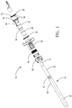
Fig. 1 is an exploded view of a shielded-cable pass-through assembly in accordance with one embodiment; -
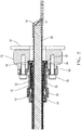
Fig. 2 is a sectional view of the shielded-cable pass-through assembly ofFig. 1 in accordance with one embodiment; -
Figs. 3A, 3B , and3C are views of parts used to form the shielded-cable pass-through assembly ofFigs. 1 and2 in accordance with one embodiment; -
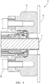
Fig. 4 is a close-up sectional side view of part of the assembly ofFig. 1 ; and -
Fig. 5 is a close-up sectional side view of part of the assembly ofFig. 4 . -
Figs. 1 and2 illustrate a non-limiting example of a shielded-cable pass-throughassembly 10, hereafter referred to as theassembly 10, which is generally configured to provide electrical contact between a shielding-layer 12 of a shielded-cable 14 and a boundary 16 (Fig. 2 ) through which the shielded-cable 14 passes. In this example the shielded-cable 14 is illustrated as having a single-conductor 18 covered or wrapped by an insulation-layer 20, where the single-conductor 18 may be sized to be suitable for conducting current from a battery (not shown) in an electric-vehicle (not shown). However, the single-conductor 18 is not a requirement as it is contemplated that multiple-conductors may be covered by the insulation-layer 20 with the shielding-layer 12 providing electro-magnetic protection to the multiple-conductors. It is also contemplated that the features and parts of theassembly 10 could be duplicated in parallel to form a unitized 2-way, 3-way, or more-way assembly for multiple parallel instances of the single-conductor 18. For reliability and durability reasons it is preferred that the shielding-layer 12 be a braided wire type shielding. However, this is not a requirement as it is contemplated that the shielding-layer 12 could be formed of metallic-foil, with an optional single wire conductor, as will be recognized by those in the art. - The
boundary 16 may be a metal body panel of a vehicle or enclosure for electrical equipment. Theboundary 16 may include aninterface 70 such as the interface which is shown by Marsh et al. in United States Patent Number8,585,415 issued Nov. 19, 2013 , or corresponding Chinese Patent Number102341965 issued July 15, 2015 ; see reference number 118 in those documents. Theinterface 70 is preferably formed of metal and may be welded or otherwise attached to theboundary 16 in a manner that provides for an electrical connection between theinterface 70 and theboundary 16. Theassembly 10 may also include various seals, fixtures, and fasteners used to attach theassembly 10 to the interface orboundary 16. - The
assembly 10 includes a metallic-sleeve 22 that defines a shield-surface 24 used to make electrical contact with the shielding-layer 12 of a shielded-cable 14. The shielded-cable 14 may be prepared (i.e. stripped) as suggested inFig. 1 by removing portions of the outer-cover 26, the shielding-layer 12, and the insulation-layer 20. The portion of the metallic-sleeve 22 that defines the shield-surface 24 is typically sized to slide over the insulation-layer 20 and underneath the shielding-layer 12. The metallic-sleeve 22 may be formed of brass, plated steel, or any other material suitable to make a reliable electrical connection with the shielding-layer 12. - The
assembly 10 may also include aferrule 28 that is crimped over the shielding-layer 12 around where the shielding-layer 12 makes contact with the shield-surface 24 of the metallic-sleeve 22 to urge the shielding-layer 12 of the shielded-cable 14 into reliable electrical contact with the shield-surface 24. Like the metallic-sleeve 22, theferrule 28 may be formed of brass, plated steel, or any other material suitable to crimp and thereby make a reliable electrical connection between with the shielding-layer 12 and the shield-surface 24. - The
assembly 10 includes a contact-terminal 30 that defines a contact-feature 32 (Fig. 3A ) that may be used to make electrical contact with theboundary 16 when theassembly 10 is attached to theboundary 16. The contact-terminal 30 includes or defines a plurality of inner-contact-fingers 34 extending from the contact-terminal 30 in a longitudinal-direction 36 (Fig. 3C ) parallel to a longitudinal-axis 38 (Fig 1 ) of the shielded-cable 14. The material used to form the contact-terminal 30 (e.g. beryllium-copper) and the shape of the inner-contact-fingers cooperate so that the plurality of inner-contact-fingers 34 are urged in a radial-direction 40 (Fig. 3C ) to make electrical contact with a contact-surface 42 of the metallic-sleeve 22 after theassembly 10 is assembled. That is, the plurality of inner-contact-fingers 34 maintains a spring-loaded contact with the contact-surface 42 once assembled. While the contact-surface 42 is shown in this non-limiting example as being on the inside of the metallic-sleeve 22 so that the radial-direction 40 is radially outward, this is not a requirement. It is contemplated that contact-surface 42 could be on the outside of the metallic-sleeve 22 and the plurality of inner-contact-fingers 34 could be configured to be urged or press against the metallic-sleeve 22 from the outside in a radially inward direction. - The contact-
feature 32 or the contact-terminal 30 may be further configured to define a plurality of outer-contact-fingers 66 that are urged in an other-radial-direction 68 (Fig. 5 ) to make electrical contact with theinterface 70 after theassembly 10 is assembled. In this example the other-radial-direction 68 corresponds to the radial-direction 40. However, similar to what was mentioned above, other configurations are envisioned where the other-radial-direction 68 is opposite to the radial-direction 40, either in a radially inward direction or a radially outward direction. - The
assembly 10 may include aretainer 44 that defines a tab orhook 46 that fits into anopening 48 defined by the metallic-sleeve 22. Thehook 46 and theopening 48 are configured to cooperate with each other to retain the metallic-sleeve 22 on theretainer 44 and prevent rotation of the metallic-sleeve 22 relative to theretainer 44 after theassembly 10 is assembled. Theretainer 44 may also define a plurality ofpassageways 50 through which the plurality of inner-contact-fingers 34 passes after theassembly 10 is assembled, or at least the contact-terminal 30 and theretainer 44 are assembled. The plurality ofpassageways 50 and the plurality of inner-contact-fingers 34 cooperate to prevent rotation of the contact-terminal 30 relative to theretainer 44 after the assembly is assembled. The prevention of rotation of the various parts is advantageous as it helps to reduce wear of the various points of electrical contact used to form the electrical connection between the shielding-layer 12 and theboundary 16. - The
assembly 10 may include ahousing 52 that cooperates with a peripheral-seal 54 and a wire-seal 56 to cover and protect from moisture and other contaminates the parts inside the housing that form the electrical connection between the shielding-layer 12 and theboundary 16. Thehousing 52 may be further configure to support the shielded-cable 14 and provide thenecessary features 60 sofasteners 58 can be used to fix or attach theassembly 10 to theboundary 16. Theassembly 10 may include a lock-insert 62 that cooperates with acover 64 to secure the wire-seal 56 and provide strain relief for the shielded-cable 14. - Accordingly, a shielded-cable pass-through assembly (the assembly 10) is provided that provides a convenient, economical, and reliable way to make an electrical contact between a shielding-layer of a shielded-cable and a boundary through which the shielded-cable passes.
- While this invention has been described in terms of the preferred embodiments thereof, it is not intended to be so limited, but rather only to the extent set forth in the claims that follow.
Claims (5)
- A shielded-cable pass-through assembly (10) configured to provide electrical contact between a shielding-layer (12) of a shielded-cable (14) and a boundary (16) through which the shielded-cable (14) passes, said assembly (10) comprising:a metallic-sleeve (22) that defines a shield-surface (24) used to make electrical contact with a shielding-layer (12) of a shielded-cable (14);a contact-terminal (30) that defines a contact-feature (32) used to make electrical contact with the boundary (16) through which the shielded-cable (14) passes, and defines a plurality of inner-contact-fingers (34) extending from the contact-terminal (30) in a longitudinal-direction (36) parallel to a longitudinal-axis (38) of the shielded-cable (14), wherein the plurality of inner-contact-fingers (34) is urged in a radial-direction (40) to make electrical contact with a contact-surface (42) of the metallic-sleeve (22) after the assembly (10) is assembled.
- The assembly (10) in accordance with claim 1, wherein the boundary (16) includes an interface (70) and the contact-terminal (30) defines a plurality of outer-contact-fingers (66) urged in another-radial-direction (40) to make electrical contact with an interface (70) after the assembly (10) is assembled.
- The assembly (10) in accordance with claim 1 or 2, wherein the assembly (10) includes a retainer (44) that defines a hook (46) that fits into an opening (48) defined by the metallic-sleeve (22), wherein the hook (46) and the opening (48) cooperate to retain the metallic-sleeve (22) on the retainer (44) and prevent rotation of the metallic-sleeve (22) relative to the retainer (44) after the assembly (10) is assembled.
- The assembly (10) in accordance with claim 3, wherein the retainer (44) defines a plurality of passageways (50) through which the plurality of inner-contact-fingers (34) passes after the assembly (10) is assembled, wherein the plurality of passageways (50) and the plurality of inner-contact-fingers (34) cooperate to prevent rotation of the contact-terminal (30) relative to the retainer (44) after the assembly (10) is assembled.
- The assembly (10) in accordance with any one of the preceding claims, wherein the assembly (10) includes a ferrule (28) that is crimped around the shield-surface (24) of the metallic-sleeve (22) to urge the shielding-layer (12) of the shielded-cable (14) into electrical contact with the shield-surface (24).
Applications Claiming Priority (1)
| Application Number | Priority Date | Filing Date | Title |
|---|---|---|---|
| PCT/CN2016/113566 WO2018120045A1 (en) | 2016-12-30 | 2016-12-30 | Shielded cable penetrable component with boundary contact |
Publications (3)
| Publication Number | Publication Date |
|---|---|
| EP3565066A1 true EP3565066A1 (en) | 2019-11-06 |
| EP3565066A4 EP3565066A4 (en) | 2020-08-12 |
| EP3565066B1 EP3565066B1 (en) | 2022-08-17 |
Family
ID=62707629
Family Applications (1)
| Application Number | Title | Priority Date | Filing Date |
|---|---|---|---|
| EP16925803.5A Active EP3565066B1 (en) | 2016-12-30 | 2016-12-30 | Shielded cable penetrable component with boundary contact |
Country Status (4)
| Country | Link |
|---|---|
| US (1) | US11114804B2 (en) |
| EP (1) | EP3565066B1 (en) |
| CN (1) | CN110168810B (en) |
| WO (1) | WO2018120045A1 (en) |
Families Citing this family (5)
| Publication number | Priority date | Publication date | Assignee | Title |
|---|---|---|---|---|
| CN208078201U (en) * | 2018-03-21 | 2018-11-09 | 精进电动科技股份有限公司 | A kind of joint structure of high voltage cable |
| CN117712752A (en) | 2022-09-13 | 2024-03-15 | 李尔公司 | Cap assembly for electrical pathway |
| CN117712732A (en) | 2022-09-13 | 2024-03-15 | 李尔公司 | Contact components for electrical pathways |
| CN117712753A (en) | 2022-09-13 | 2024-03-15 | 李尔公司 | Housing for an electrical path |
| DE102022129113A1 (en) * | 2022-11-03 | 2024-05-08 | Te Connectivity Germany Gmbh | Shielded electrical unit connector for a vehicle unit |
Family Cites Families (25)
| Publication number | Priority date | Publication date | Assignee | Title |
|---|---|---|---|---|
| US4183605A (en) * | 1976-07-26 | 1980-01-15 | Automation Industries, Inc. | Electrical connector with arcuate detent means |
| CA1070792A (en) * | 1976-07-26 | 1980-01-29 | Earl A. Cooper | Electrical connector and frequency shielding means therefor and method of making same |
| US4488765A (en) * | 1980-06-18 | 1984-12-18 | The United States Of America As Represented By The Secretary Of The Navy | Dead-faced electrical connector with electromagnetic vulnerability protection |
| US4377320A (en) * | 1980-11-26 | 1983-03-22 | Amp Incorporated | Coaxial connector |
| US4408816A (en) * | 1981-11-25 | 1983-10-11 | Midland-Ross Corporation | Terminator connector for shielded cables |
| JPS61201283U (en) * | 1985-06-07 | 1986-12-17 | ||
| US5180316A (en) * | 1991-03-25 | 1993-01-19 | Molex Incorporated | Shielded electrical connector |
| US6305963B1 (en) * | 1996-08-16 | 2001-10-23 | Agilent Technologies, Inc. | Push-lock BNC connector |
| US6042396A (en) * | 1997-10-03 | 2000-03-28 | Yazaki Corporation | Terminal treatment structure of a shield wire |
| JP3251540B2 (en) * | 1997-10-21 | 2002-01-28 | 矢崎総業株式会社 | Termination treatment structure and termination treatment method for shielded wires |
| JP3627209B2 (en) * | 1999-04-07 | 2005-03-09 | 矢崎総業株式会社 | Shield connector structure |
| JP4469704B2 (en) * | 2004-11-11 | 2010-05-26 | 株式会社オーディオテクニカ | Condenser microphone |
| US7654856B2 (en) * | 2008-05-27 | 2010-02-02 | Hon Hai Precision Ind. Co., Ltd | Cable connector assembly having strain relief member for cable |
| CN201303150Y (en) | 2008-11-06 | 2009-09-02 | 富士康(昆山)电脑接插件有限公司 | Cable connector |
| EP2343783A1 (en) | 2008-11-06 | 2011-07-13 | Hon Hai Precision Industry Co., Ltd. | Cable end connector assembly |
| EP2254199B1 (en) | 2009-03-02 | 2011-10-19 | Tyco Electronics UK Ltd. | Shielding braid termination for a shielded electrical connector |
| TWI549386B (en) * | 2010-04-13 | 2016-09-11 | 康寧吉伯特公司 | Coaxial connector with inhibited ingress and improved grounding |
| JP5622307B2 (en) * | 2010-07-05 | 2014-11-12 | 矢崎総業株式会社 | Shield connector |
| CN101950892A (en) | 2010-08-31 | 2011-01-19 | 苏州华旃航天电器有限公司 | Shielding tail accessory structure |
| JP6234034B2 (en) | 2013-02-20 | 2017-11-22 | 矢崎総業株式会社 | Shield connector structure |
| JP6033113B2 (en) | 2013-02-20 | 2016-11-30 | 矢崎総業株式会社 | Shield braided wire connection structure and shield connector |
| CN203690653U (en) | 2014-02-08 | 2014-07-02 | 太康精密股份有限公司 | Switching structure and cable connector with switching structure |
| US9653823B2 (en) * | 2014-05-19 | 2017-05-16 | Ppc Broadband, Inc. | Connector having installation-responsive compression |
| CN205231371U (en) | 2015-12-18 | 2016-05-11 | 德尔福中央电气(上海)有限公司 | Shield connection structure for cable fitting |
| CN205646199U (en) | 2016-04-17 | 2016-10-12 | 江苏赛洋机电科技有限公司 | Connector shell and reliable connection structure of cable shield layer |
-
2016
- 2016-12-30 CN CN201680091950.7A patent/CN110168810B/en active Active
- 2016-12-30 WO PCT/CN2016/113566 patent/WO2018120045A1/en not_active Ceased
- 2016-12-30 EP EP16925803.5A patent/EP3565066B1/en active Active
- 2016-12-30 US US16/473,387 patent/US11114804B2/en active Active
Also Published As
| Publication number | Publication date |
|---|---|
| US11114804B2 (en) | 2021-09-07 |
| EP3565066B1 (en) | 2022-08-17 |
| US20200144771A1 (en) | 2020-05-07 |
| CN110168810B (en) | 2021-05-28 |
| CN110168810A (en) | 2019-08-23 |
| EP3565066A4 (en) | 2020-08-12 |
| WO2018120045A1 (en) | 2018-07-05 |
Similar Documents
| Publication | Publication Date | Title |
|---|---|---|
| EP3565066B1 (en) | Shielded cable penetrable component with boundary contact | |
| US10574001B2 (en) | High power electrical connector | |
| EP2681808B1 (en) | Connector with housing having spacer including a pair of projections | |
| DE102013017108B4 (en) | Device connector and method of assembling same | |
| EP2500991B1 (en) | Mounting structure for shielding shell and mounting method therefor | |
| EP2698882B1 (en) | Shield connector | |
| US10490931B2 (en) | Seal member and electrical connector | |
| EP2715879B1 (en) | Connecting structure of shield braided part | |
| JP4909793B2 (en) | Shield connector | |
| EP3326245A1 (en) | Terminal fitting | |
| CN106663884B (en) | cable connection member | |
| DE112019004989T5 (en) | Plug connector and connector device | |
| EP2894722B1 (en) | Terminal | |
| DE102013220498A1 (en) | Shielded connector | |
| DE102018209129A1 (en) | Resin-containing seal and water-impermeable connection device | |
| JPH11127515A (en) | Terminal treatment structure and terminal treatment method of shielded electric wire | |
| DE102022000862A1 (en) | Connectors, wiring and assembly methods therefor | |
| US7044795B2 (en) | Miniature, shielded electrical connector with strain relief | |
| JP2001135419A (en) | Terminal processing method and terminal processing structure of shielded cable | |
| US20150303611A1 (en) | Shielded connector | |
| DE102012100149A1 (en) | Electric cable holder and method for connecting the same. | |
| DE112015002628T5 (en) | Interconnects | |
| DE102022119598A1 (en) | connector connection structure | |
| DE102012208207A1 (en) | Ground conductor connection system | |
| DE102023002670B3 (en) | Cable connectors |
Legal Events
| Date | Code | Title | Description |
|---|---|---|---|
| STAA | Information on the status of an ep patent application or granted ep patent |
Free format text: STATUS: THE INTERNATIONAL PUBLICATION HAS BEEN MADE |
|
| PUAI | Public reference made under article 153(3) epc to a published international application that has entered the european phase |
Free format text: ORIGINAL CODE: 0009012 |
|
| STAA | Information on the status of an ep patent application or granted ep patent |
Free format text: STATUS: REQUEST FOR EXAMINATION WAS MADE |
|
| 17P | Request for examination filed |
Effective date: 20190716 |
|
| AK | Designated contracting states |
Kind code of ref document: A1 Designated state(s): AL AT BE BG CH CY CZ DE DK EE ES FI FR GB GR HR HU IE IS IT LI LT LU LV MC MK MT NL NO PL PT RO RS SE SI SK SM TR |
|
| AX | Request for extension of the european patent |
Extension state: BA ME |
|
| DAV | Request for validation of the european patent (deleted) | ||
| DAX | Request for extension of the european patent (deleted) | ||
| A4 | Supplementary search report drawn up and despatched |
Effective date: 20200715 |
|
| RIC1 | Information provided on ipc code assigned before grant |
Ipc: H01R 13/658 20110101AFI20200709BHEP Ipc: H01R 9/05 20060101ALI20200709BHEP Ipc: H01R 13/502 20060101ALI20200709BHEP Ipc: H01R 13/6596 20110101ALI20200709BHEP Ipc: H01R 13/6593 20110101ALI20200709BHEP |
|
| GRAP | Despatch of communication of intention to grant a patent |
Free format text: ORIGINAL CODE: EPIDOSNIGR1 |
|
| STAA | Information on the status of an ep patent application or granted ep patent |
Free format text: STATUS: GRANT OF PATENT IS INTENDED |
|
| INTG | Intention to grant announced |
Effective date: 20211025 |
|
| GRAJ | Information related to disapproval of communication of intention to grant by the applicant or resumption of examination proceedings by the epo deleted |
Free format text: ORIGINAL CODE: EPIDOSDIGR1 |
|
| STAA | Information on the status of an ep patent application or granted ep patent |
Free format text: STATUS: REQUEST FOR EXAMINATION WAS MADE |
|
| GRAS | Grant fee paid |
Free format text: ORIGINAL CODE: EPIDOSNIGR3 |
|
| STAA | Information on the status of an ep patent application or granted ep patent |
Free format text: STATUS: GRANT OF PATENT IS INTENDED |
|
| GRAP | Despatch of communication of intention to grant a patent |
Free format text: ORIGINAL CODE: EPIDOSNIGR1 |
|
| INTC | Intention to grant announced (deleted) | ||
| RAP1 | Party data changed (applicant data changed or rights of an application transferred) |
Owner name: APTIV TECHNOLOGIES LIMITED |
|
| INTG | Intention to grant announced |
Effective date: 20220325 |
|
| GRAA | (expected) grant |
Free format text: ORIGINAL CODE: 0009210 |
|
| STAA | Information on the status of an ep patent application or granted ep patent |
Free format text: STATUS: THE PATENT HAS BEEN GRANTED |
|
| AK | Designated contracting states |
Kind code of ref document: B1 Designated state(s): AL AT BE BG CH CY CZ DE DK EE ES FI FR GB GR HR HU IE IS IT LI LT LU LV MC MK MT NL NO PL PT RO RS SE SI SK SM TR |
|
| REG | Reference to a national code |
Ref country code: CH Ref legal event code: EP |
|
| REG | Reference to a national code |
Ref country code: DE Ref legal event code: R096 Ref document number: 602016074426 Country of ref document: DE |
|
| REG | Reference to a national code |
Ref country code: IE Ref legal event code: FG4D |
|
| REG | Reference to a national code |
Ref country code: AT Ref legal event code: REF Ref document number: 1512783 Country of ref document: AT Kind code of ref document: T Effective date: 20220915 |
|
| REG | Reference to a national code |
Ref country code: NL Ref legal event code: MP Effective date: 20220817 |
|
| REG | Reference to a national code |
Ref country code: LT Ref legal event code: MG9D |
|
| PG25 | Lapsed in a contracting state [announced via postgrant information from national office to epo] |
Ref country code: SE Free format text: LAPSE BECAUSE OF FAILURE TO SUBMIT A TRANSLATION OF THE DESCRIPTION OR TO PAY THE FEE WITHIN THE PRESCRIBED TIME-LIMIT Effective date: 20220817 Ref country code: RS Free format text: LAPSE BECAUSE OF FAILURE TO SUBMIT A TRANSLATION OF THE DESCRIPTION OR TO PAY THE FEE WITHIN THE PRESCRIBED TIME-LIMIT Effective date: 20220817 Ref country code: PT Free format text: LAPSE BECAUSE OF FAILURE TO SUBMIT A TRANSLATION OF THE DESCRIPTION OR TO PAY THE FEE WITHIN THE PRESCRIBED TIME-LIMIT Effective date: 20221219 Ref country code: NO Free format text: LAPSE BECAUSE OF FAILURE TO SUBMIT A TRANSLATION OF THE DESCRIPTION OR TO PAY THE FEE WITHIN THE PRESCRIBED TIME-LIMIT Effective date: 20221117 Ref country code: NL Free format text: LAPSE BECAUSE OF FAILURE TO SUBMIT A TRANSLATION OF THE DESCRIPTION OR TO PAY THE FEE WITHIN THE PRESCRIBED TIME-LIMIT Effective date: 20220817 Ref country code: LV Free format text: LAPSE BECAUSE OF FAILURE TO SUBMIT A TRANSLATION OF THE DESCRIPTION OR TO PAY THE FEE WITHIN THE PRESCRIBED TIME-LIMIT Effective date: 20220817 Ref country code: LT Free format text: LAPSE BECAUSE OF FAILURE TO SUBMIT A TRANSLATION OF THE DESCRIPTION OR TO PAY THE FEE WITHIN THE PRESCRIBED TIME-LIMIT Effective date: 20220817 Ref country code: FI Free format text: LAPSE BECAUSE OF FAILURE TO SUBMIT A TRANSLATION OF THE DESCRIPTION OR TO PAY THE FEE WITHIN THE PRESCRIBED TIME-LIMIT Effective date: 20220817 |
|
| REG | Reference to a national code |
Ref country code: AT Ref legal event code: MK05 Ref document number: 1512783 Country of ref document: AT Kind code of ref document: T Effective date: 20220817 |
|
| PG25 | Lapsed in a contracting state [announced via postgrant information from national office to epo] |
Ref country code: PL Free format text: LAPSE BECAUSE OF FAILURE TO SUBMIT A TRANSLATION OF THE DESCRIPTION OR TO PAY THE FEE WITHIN THE PRESCRIBED TIME-LIMIT Effective date: 20220817 Ref country code: IS Free format text: LAPSE BECAUSE OF FAILURE TO SUBMIT A TRANSLATION OF THE DESCRIPTION OR TO PAY THE FEE WITHIN THE PRESCRIBED TIME-LIMIT Effective date: 20221217 Ref country code: HR Free format text: LAPSE BECAUSE OF FAILURE TO SUBMIT A TRANSLATION OF THE DESCRIPTION OR TO PAY THE FEE WITHIN THE PRESCRIBED TIME-LIMIT Effective date: 20220817 Ref country code: GR Free format text: LAPSE BECAUSE OF FAILURE TO SUBMIT A TRANSLATION OF THE DESCRIPTION OR TO PAY THE FEE WITHIN THE PRESCRIBED TIME-LIMIT Effective date: 20221118 |
|
| RAP4 | Party data changed (patent owner data changed or rights of a patent transferred) |
Owner name: APTIV TECHNOLOGIES LIMITED |
|
| PG25 | Lapsed in a contracting state [announced via postgrant information from national office to epo] |
Ref country code: SM Free format text: LAPSE BECAUSE OF FAILURE TO SUBMIT A TRANSLATION OF THE DESCRIPTION OR TO PAY THE FEE WITHIN THE PRESCRIBED TIME-LIMIT Effective date: 20220817 Ref country code: RO Free format text: LAPSE BECAUSE OF FAILURE TO SUBMIT A TRANSLATION OF THE DESCRIPTION OR TO PAY THE FEE WITHIN THE PRESCRIBED TIME-LIMIT Effective date: 20220817 Ref country code: ES Free format text: LAPSE BECAUSE OF FAILURE TO SUBMIT A TRANSLATION OF THE DESCRIPTION OR TO PAY THE FEE WITHIN THE PRESCRIBED TIME-LIMIT Effective date: 20220817 Ref country code: DK Free format text: LAPSE BECAUSE OF FAILURE TO SUBMIT A TRANSLATION OF THE DESCRIPTION OR TO PAY THE FEE WITHIN THE PRESCRIBED TIME-LIMIT Effective date: 20220817 Ref country code: CZ Free format text: LAPSE BECAUSE OF FAILURE TO SUBMIT A TRANSLATION OF THE DESCRIPTION OR TO PAY THE FEE WITHIN THE PRESCRIBED TIME-LIMIT Effective date: 20220817 Ref country code: AT Free format text: LAPSE BECAUSE OF FAILURE TO SUBMIT A TRANSLATION OF THE DESCRIPTION OR TO PAY THE FEE WITHIN THE PRESCRIBED TIME-LIMIT Effective date: 20220817 |
|
| REG | Reference to a national code |
Ref country code: DE Ref legal event code: R097 Ref document number: 602016074426 Country of ref document: DE |
|
| PG25 | Lapsed in a contracting state [announced via postgrant information from national office to epo] |
Ref country code: SK Free format text: LAPSE BECAUSE OF FAILURE TO SUBMIT A TRANSLATION OF THE DESCRIPTION OR TO PAY THE FEE WITHIN THE PRESCRIBED TIME-LIMIT Effective date: 20220817 Ref country code: EE Free format text: LAPSE BECAUSE OF FAILURE TO SUBMIT A TRANSLATION OF THE DESCRIPTION OR TO PAY THE FEE WITHIN THE PRESCRIBED TIME-LIMIT Effective date: 20220817 |
|
| P01 | Opt-out of the competence of the unified patent court (upc) registered |
Effective date: 20230424 |
|
| PLBE | No opposition filed within time limit |
Free format text: ORIGINAL CODE: 0009261 |
|
| STAA | Information on the status of an ep patent application or granted ep patent |
Free format text: STATUS: NO OPPOSITION FILED WITHIN TIME LIMIT |
|
| PG25 | Lapsed in a contracting state [announced via postgrant information from national office to epo] |
Ref country code: AL Free format text: LAPSE BECAUSE OF FAILURE TO SUBMIT A TRANSLATION OF THE DESCRIPTION OR TO PAY THE FEE WITHIN THE PRESCRIBED TIME-LIMIT Effective date: 20220817 |
|
| 26N | No opposition filed |
Effective date: 20230519 |
|
| REG | Reference to a national code |
Ref country code: CH Ref legal event code: PL |
|
| REG | Reference to a national code |
Ref country code: BE Ref legal event code: MM Effective date: 20221231 |
|
| PG25 | Lapsed in a contracting state [announced via postgrant information from national office to epo] |
Ref country code: SI Free format text: LAPSE BECAUSE OF FAILURE TO SUBMIT A TRANSLATION OF THE DESCRIPTION OR TO PAY THE FEE WITHIN THE PRESCRIBED TIME-LIMIT Effective date: 20220817 Ref country code: LU Free format text: LAPSE BECAUSE OF NON-PAYMENT OF DUE FEES Effective date: 20221230 |
|
| PG25 | Lapsed in a contracting state [announced via postgrant information from national office to epo] |
Ref country code: LI Free format text: LAPSE BECAUSE OF NON-PAYMENT OF DUE FEES Effective date: 20221231 Ref country code: IE Free format text: LAPSE BECAUSE OF NON-PAYMENT OF DUE FEES Effective date: 20221230 Ref country code: CH Free format text: LAPSE BECAUSE OF NON-PAYMENT OF DUE FEES Effective date: 20221231 |
|
| PG25 | Lapsed in a contracting state [announced via postgrant information from national office to epo] |
Ref country code: BE Free format text: LAPSE BECAUSE OF NON-PAYMENT OF DUE FEES Effective date: 20221231 |
|
| PG25 | Lapsed in a contracting state [announced via postgrant information from national office to epo] |
Ref country code: HU Free format text: LAPSE BECAUSE OF FAILURE TO SUBMIT A TRANSLATION OF THE DESCRIPTION OR TO PAY THE FEE WITHIN THE PRESCRIBED TIME-LIMIT; INVALID AB INITIO Effective date: 20161230 |
|
| PG25 | Lapsed in a contracting state [announced via postgrant information from national office to epo] |
Ref country code: CY Free format text: LAPSE BECAUSE OF FAILURE TO SUBMIT A TRANSLATION OF THE DESCRIPTION OR TO PAY THE FEE WITHIN THE PRESCRIBED TIME-LIMIT Effective date: 20220817 |
|
| PG25 | Lapsed in a contracting state [announced via postgrant information from national office to epo] |
Ref country code: MK Free format text: LAPSE BECAUSE OF FAILURE TO SUBMIT A TRANSLATION OF THE DESCRIPTION OR TO PAY THE FEE WITHIN THE PRESCRIBED TIME-LIMIT Effective date: 20220817 Ref country code: IT Free format text: LAPSE BECAUSE OF FAILURE TO SUBMIT A TRANSLATION OF THE DESCRIPTION OR TO PAY THE FEE WITHIN THE PRESCRIBED TIME-LIMIT Effective date: 20220817 |
|
| PG25 | Lapsed in a contracting state [announced via postgrant information from national office to epo] |
Ref country code: MC Free format text: LAPSE BECAUSE OF FAILURE TO SUBMIT A TRANSLATION OF THE DESCRIPTION OR TO PAY THE FEE WITHIN THE PRESCRIBED TIME-LIMIT Effective date: 20220817 |
|
| PG25 | Lapsed in a contracting state [announced via postgrant information from national office to epo] |
Ref country code: TR Free format text: LAPSE BECAUSE OF FAILURE TO SUBMIT A TRANSLATION OF THE DESCRIPTION OR TO PAY THE FEE WITHIN THE PRESCRIBED TIME-LIMIT Effective date: 20220817 Ref country code: MC Free format text: LAPSE BECAUSE OF FAILURE TO SUBMIT A TRANSLATION OF THE DESCRIPTION OR TO PAY THE FEE WITHIN THE PRESCRIBED TIME-LIMIT Effective date: 20220817 |
|
| PG25 | Lapsed in a contracting state [announced via postgrant information from national office to epo] |
Ref country code: BG Free format text: LAPSE BECAUSE OF FAILURE TO SUBMIT A TRANSLATION OF THE DESCRIPTION OR TO PAY THE FEE WITHIN THE PRESCRIBED TIME-LIMIT Effective date: 20220817 |
|
| PG25 | Lapsed in a contracting state [announced via postgrant information from national office to epo] |
Ref country code: MT Free format text: LAPSE BECAUSE OF FAILURE TO SUBMIT A TRANSLATION OF THE DESCRIPTION OR TO PAY THE FEE WITHIN THE PRESCRIBED TIME-LIMIT Effective date: 20220817 |
|
| REG | Reference to a national code |
Ref country code: DE Ref legal event code: R081 Ref document number: 602016074426 Country of ref document: DE Owner name: APTIV TECHNOLOGIES AG, CH Free format text: FORMER OWNER: APTIV TECHNOLOGIES LIMITED, ST. MICHAEL, BB |
|
| PGFP | Annual fee paid to national office [announced via postgrant information from national office to epo] |
Ref country code: DE Payment date: 20251117 Year of fee payment: 10 |
|
| PGFP | Annual fee paid to national office [announced via postgrant information from national office to epo] |
Ref country code: GB Payment date: 20251210 Year of fee payment: 10 |
|
| PGFP | Annual fee paid to national office [announced via postgrant information from national office to epo] |
Ref country code: FR Payment date: 20251202 Year of fee payment: 10 |