EP3565029A1 - Protection device used in battery pack, battery pack and vehicle - Google Patents
Protection device used in battery pack, battery pack and vehicle Download PDFInfo
- Publication number
- EP3565029A1 EP3565029A1 EP17888533.1A EP17888533A EP3565029A1 EP 3565029 A1 EP3565029 A1 EP 3565029A1 EP 17888533 A EP17888533 A EP 17888533A EP 3565029 A1 EP3565029 A1 EP 3565029A1
- Authority
- EP
- European Patent Office
- Prior art keywords
- connecting assembly
- battery
- protection device
- assembly
- battery pack
- Prior art date
- Legal status (The legal status is an assumption and is not a legal conclusion. Google has not performed a legal analysis and makes no representation as to the accuracy of the status listed.)
- Pending
Links
- 230000004913 activation Effects 0.000 claims description 23
- 239000002184 metal Substances 0.000 claims description 5
- 229910052751 metal Inorganic materials 0.000 claims description 5
- 229910001285 shape-memory alloy Inorganic materials 0.000 claims description 3
- 238000004880 explosion Methods 0.000 description 13
- 238000001816 cooling Methods 0.000 description 9
- 239000002360 explosive Substances 0.000 description 4
- 230000002708 enhancing effect Effects 0.000 description 3
- 238000007747 plating Methods 0.000 description 3
- PXHVJJICTQNCMI-UHFFFAOYSA-N Nickel Chemical compound [Ni] PXHVJJICTQNCMI-UHFFFAOYSA-N 0.000 description 2
- 230000009471 action Effects 0.000 description 2
- 238000004891 communication Methods 0.000 description 2
- 239000000463 material Substances 0.000 description 2
- 239000011159 matrix material Substances 0.000 description 2
- 239000000523 sample Substances 0.000 description 2
- RYGMFSIKBFXOCR-UHFFFAOYSA-N Copper Chemical compound [Cu] RYGMFSIKBFXOCR-UHFFFAOYSA-N 0.000 description 1
- BQCADISMDOOEFD-UHFFFAOYSA-N Silver Chemical compound [Ag] BQCADISMDOOEFD-UHFFFAOYSA-N 0.000 description 1
- 230000002159 abnormal effect Effects 0.000 description 1
- 230000008859 change Effects 0.000 description 1
- 238000010276 construction Methods 0.000 description 1
- 229910052802 copper Inorganic materials 0.000 description 1
- 239000010949 copper Substances 0.000 description 1
- PCHJSUWPFVWCPO-UHFFFAOYSA-N gold Chemical compound [Au] PCHJSUWPFVWCPO-UHFFFAOYSA-N 0.000 description 1
- 229910052737 gold Inorganic materials 0.000 description 1
- 239000010931 gold Substances 0.000 description 1
- 230000020169 heat generation Effects 0.000 description 1
- 230000010354 integration Effects 0.000 description 1
- 238000004519 manufacturing process Methods 0.000 description 1
- 238000012986 modification Methods 0.000 description 1
- 230000004048 modification Effects 0.000 description 1
- 229910052759 nickel Inorganic materials 0.000 description 1
- 238000013021 overheating Methods 0.000 description 1
- 230000003647 oxidation Effects 0.000 description 1
- 238000007254 oxidation reaction Methods 0.000 description 1
- 238000005192 partition Methods 0.000 description 1
- 229910052709 silver Inorganic materials 0.000 description 1
- 239000004332 silver Substances 0.000 description 1
Images



Classifications
-
- H—ELECTRICITY
- H01—ELECTRIC ELEMENTS
- H01M—PROCESSES OR MEANS, e.g. BATTERIES, FOR THE DIRECT CONVERSION OF CHEMICAL ENERGY INTO ELECTRICAL ENERGY
- H01M50/00—Constructional details or processes of manufacture of the non-active parts of electrochemical cells other than fuel cells, e.g. hybrid cells
- H01M50/20—Mountings; Secondary casings or frames; Racks, modules or packs; Suspension devices; Shock absorbers; Transport or carrying devices; Holders
- H01M50/204—Racks, modules or packs for multiple batteries or multiple cells
- H01M50/207—Racks, modules or packs for multiple batteries or multiple cells characterised by their shape
- H01M50/209—Racks, modules or packs for multiple batteries or multiple cells characterised by their shape adapted for prismatic or rectangular cells
-
- H—ELECTRICITY
- H01—ELECTRIC ELEMENTS
- H01M—PROCESSES OR MEANS, e.g. BATTERIES, FOR THE DIRECT CONVERSION OF CHEMICAL ENERGY INTO ELECTRICAL ENERGY
- H01M50/00—Constructional details or processes of manufacture of the non-active parts of electrochemical cells other than fuel cells, e.g. hybrid cells
- H01M50/50—Current conducting connections for cells or batteries
- H01M50/572—Means for preventing undesired use or discharge
- H01M50/574—Devices or arrangements for the interruption of current
-
- H—ELECTRICITY
- H01—ELECTRIC ELEMENTS
- H01M—PROCESSES OR MEANS, e.g. BATTERIES, FOR THE DIRECT CONVERSION OF CHEMICAL ENERGY INTO ELECTRICAL ENERGY
- H01M50/00—Constructional details or processes of manufacture of the non-active parts of electrochemical cells other than fuel cells, e.g. hybrid cells
- H01M50/50—Current conducting connections for cells or batteries
- H01M50/572—Means for preventing undesired use or discharge
- H01M50/574—Devices or arrangements for the interruption of current
- H01M50/578—Devices or arrangements for the interruption of current in response to pressure
-
- H—ELECTRICITY
- H01—ELECTRIC ELEMENTS
- H01M—PROCESSES OR MEANS, e.g. BATTERIES, FOR THE DIRECT CONVERSION OF CHEMICAL ENERGY INTO ELECTRICAL ENERGY
- H01M50/00—Constructional details or processes of manufacture of the non-active parts of electrochemical cells other than fuel cells, e.g. hybrid cells
- H01M50/50—Current conducting connections for cells or batteries
- H01M50/572—Means for preventing undesired use or discharge
- H01M50/574—Devices or arrangements for the interruption of current
- H01M50/581—Devices or arrangements for the interruption of current in response to temperature
-
- H—ELECTRICITY
- H01—ELECTRIC ELEMENTS
- H01M—PROCESSES OR MEANS, e.g. BATTERIES, FOR THE DIRECT CONVERSION OF CHEMICAL ENERGY INTO ELECTRICAL ENERGY
- H01M2200/00—Safety devices for primary or secondary batteries
- H01M2200/10—Temperature sensitive devices
- H01M2200/103—Fuse
-
- H—ELECTRICITY
- H01—ELECTRIC ELEMENTS
- H01M—PROCESSES OR MEANS, e.g. BATTERIES, FOR THE DIRECT CONVERSION OF CHEMICAL ENERGY INTO ELECTRICAL ENERGY
- H01M2220/00—Batteries for particular applications
- H01M2220/20—Batteries in motive systems, e.g. vehicle, ship, plane
-
- Y—GENERAL TAGGING OF NEW TECHNOLOGICAL DEVELOPMENTS; GENERAL TAGGING OF CROSS-SECTIONAL TECHNOLOGIES SPANNING OVER SEVERAL SECTIONS OF THE IPC; TECHNICAL SUBJECTS COVERED BY FORMER USPC CROSS-REFERENCE ART COLLECTIONS [XRACs] AND DIGESTS
- Y02—TECHNOLOGIES OR APPLICATIONS FOR MITIGATION OR ADAPTATION AGAINST CLIMATE CHANGE
- Y02E—REDUCTION OF GREENHOUSE GAS [GHG] EMISSIONS, RELATED TO ENERGY GENERATION, TRANSMISSION OR DISTRIBUTION
- Y02E60/00—Enabling technologies; Technologies with a potential or indirect contribution to GHG emissions mitigation
- Y02E60/10—Energy storage using batteries
Definitions
- the present disclosure relates to the technical fields of batteries, and in particular, to a protection device for a battery pack, a battery pack and a vehicle.
- a battery module is short-circuit protected and overcharge-protected by a battery management system (BMS) and a fuse (FUSE) system, but it not only is costly, but also cannot achieve short-circuit protection between battery cells.
- BMS battery management system
- FUSE fuse
- An objective of the present disclosure is to at least resolve one of the technical problems in the related art to some extent.
- the present disclosure provides a protection device for a battery pack.
- the protection device for a battery pack has the advantages of simple structure and good reliability.
- the present disclosure is also directed to a battery pack.
- the battery pack includes the above protection device.
- the present disclosure also provides a vehicle.
- the vehicle includes the above battery pack.
- Embodiments of the present disclosure provide a protection device for a battery pack.
- the battery pack includes a plurality of batteries.
- the protection device is disposed between two adjacent batteries and includes: a first connecting assembly, the first connecting assembly being opposite to a first battery in the two adjacent batteries, and the first connecting assembly being adapted to be electrically connected with a housing of the first battery; a second connecting assembly, the second connecting assembly being opposite to a second battery in the two adjacent batteries, the second connecting assembly being adapted to be electrically connected with a housing of the second battery, and the second connecting assembly being opposite to the first connecting assembly; and a conductive connecting assembly, the conductive connecting assembly being used for being electrically connected with terminals of the first battery and the second battery, and adapted to be electrically connected with the first connecting assembly and the second connecting assembly, respectively, to be configured as an overload protection circuit.
- the protection device has a normal state and an alarm state, when the protection device is in the normal state, the first connecting assembly and the second connecting assembly are spaced apart, and the overload protection circuit is open.
- the first connecting assembly is electrically connected with the housing of the first battery
- the second connecting assembly is electrically connected with the housing of the second battery
- at least one of the first connecting assembly and the second connecting assembly moves to be electrically connected with each other, and the overload protection circuit is short-circuited.
- the protection device for a battery pack by providing the protection device between two adjacent batteries, when the battery has a safety hazard such as over-charge, short circuit, or over-temperature, the first connecting assembly and the second connecting assembly are driven to be electrically connected with each other to close the overload protection circuit. After the overload protection circuit is closed, an internal circuit of the battery pack may be fused to prevent the battery pack from being exposed to fires and explosions, thereby improving the safety performance of the battery pack.
- the protection device has a simple structure, low cost and reliable operation.
- the protection device is passive protection, thereby improving the reliability of the protection device, overcoming the safety hazards of fires and explosions for the battery pack after the failure of a battery management system (BMS), and the protection device may be used as the second protection after the failure of the BMS.
- BMS battery management system
- the conductive connecting assembly includes: a connecting piece, the connecting piece having a weakened area that is fused when the protection device is in the alarm state.
- the weakened area has a plurality of through holes spaced apart from one another.
- the thickness of the weakened area on the connecting piece is less than the thickness of the remaining positions on the connecting piece.
- the first connecting assembly and the second connecting assembly each include: a mounting base, the mounting base being provided with a mounting hole; and a contact unit, the contact unit being received in the mounting hole of the mounting base, the contact unit of the first connecting assembly being adapted to be in contact with the contact unit of the second connecting assembly.
- the contact units of the first connecting assembly and the second connecting assembly each include: an elastic member, the elastic member fitting in the mounting hole of the mounting base, a through hole being defined in the elastic member; and a contact portion, the contact portion being movably disposed in the through hole of the elastic member, the contact portion comprising a first end facing the battery opposite to the contact portion and a second end facing away from the battery opposite to the contact portion.
- the first ends of the contact portions of the first connecting assembly and the second connecting assembly extend from the mounting hole of the mounting base respectively, and the second end of the contact portion of the first connecting assembly is spaced apart from the second end of the contact portion of the second connecting assembly; and when the protection device is in the alarm state, the contact portion of the first connecting assembly and the contact portion of the second connecting assembly move toward each other until the second end of the contact portion of the first connecting assembly is in contact with the second end of the contact portion of the second connecting assembly to close the overload protection circuit.
- the first connecting assembly and the second connecting assembly each further include: a temperature relay, the temperature relay being connected with the contact unit.
- the mounting base includes a mounting groove, the mounting groove being communicated with the mounting hole, and the temperature relay being received in the mounting groove.
- the temperature relay is a memory alloy elastic piece or a bi-metal elastic piece.
- the mounting base of the first connecting assembly includes a plurality of assembly holes spaced apart from each other along the circumferential direction of the mounting base;
- the mounting base of the second connecting assembly includes a plurality of assembly holes spaced apart from each other along the circumferential direction of the mounting base; and the plurality of assembly holes on the first connecting assembly and the plurality of assembly holes on the second connecting assembly are in one-to-one correspondence.
- the protection device further includes a plurality of connecting members, each connecting member respectively passing through and fitting in one assembly hole of the first connecting assembly and one assembly hole of the second connecting assembly corresponding to the assembly hole of the first connecting assembly.
- the battery pack according to embodiments of the present disclosure includes: a plurality of batteries; a separator, the separator being disposed between two adjacent batteries; and a protection device according to the above embodiments of the present disclosure, the protection device being embedded on the separator, a first connecting assembly of the protection device being opposite to a first battery in the two adjacent batteries and being adapted to be electrically connected with a housing of the first battery, a second connecting assembly of the protection device being opposite to a second battery in the two adjacent batteries and being adapted to be electrically connected with a housing of the second battery, and a conductive connecting assembly of the protection device being electrically connected with terminals of the first battery and the second battery.
- the protection device between two adjacent batteries, when the battery has a safety hazard such as over-charge, short circuit, or over-temperature, the first connecting assembly and the second connecting assembly are driven to be electrically connected with close the overload protection circuit. After the overload protection circuit is closed, an internal circuit of the battery pack may be fused to prevent the battery pack from being exposed to fires and explosions, thereby improving the safety performance of the battery pack.
- the protection device is passive protection, thereby improving the reliability of the protection device, overcoming the safety hazards of fires and explosions for the battery pack after the failure of a battery management system (BMS), and the protection device may be used as the second protection after the failure of the BMS.
- BMS battery management system
- the housing of each battery is provided with a pressure activation piece, the pressure activation piece being opposite to the first connecting assembly or the second connecting assembly, and the pressure activation piece being electrically connected with the housing of the battery.
- the pressure activation piece is adapted to push one of the first connecting assembly and the second connecting assembly to move toward the other one, such that the first connecting assembly and the second connecting assembly are electrically connected with each other.
- the vehicle according to an embodiment of the present disclosure includes the battery pack according to the above embodiments of the present disclosure.
- the first connecting assembly and the second connecting assembly are driven to be electrically connected with close the overload protection circuit.
- an internal circuit of the battery pack may be fused to prevent the battery pack from being exposed to fires and explosions, thereby improving the safety performance of the battery pack, and further improving the overall safety of the vehicle.
- orientations or position relationships indicated by terms such as “length”, “width”, “thickness”, “up”, “down”, “front”, “back”, “left”, “right”, “vertical”, “horizontal”, “top”, “bottom”, “inner”, “outer”, and “circumferential” are orientations or position relationship shown based on the accompanying drawings, and are merely used for describing the present disclosure and simplifying the description, rather than indicating or implying that the apparatus or element should have a particular orientation or be constructed and operated in a particular orientation, and therefore, should not be construed as a limitation on the present disclosure.
- first and second are used only for description purposes, and shall not be understood as indicating or suggesting relative importance or implicitly indicating a quantity of indicated technical features. Therefore, features defined by “first” and “second” may explicitly or implicitly include at least one feature. In the description of the present disclosure, unless otherwise specifically limited, “multiple” means at least two, for example, two or three.
- mount should be understood in a generalized manner, for example, may be understood as fixed connection, detachable connection, or integration; or may be understood as mechanical connection, electrical connection, or mutual communication; or may be understood as direct connection, or indirect connection by means of a medium, or internal communication of two elements or a mutual relationship between two elements, unless otherwise clearly specified.
- a person of ordinary skill in the art may understand specific meanings of the foregoing terms in this disclosure according to a specific situation.
- a protection device 100 for a battery pack 500, a battery pack 500 and a vehicle according to an embodiment of the present disclosure will be described below with reference to FIGS. 1-8 .
- the battery pack 500 includes a plurality of batteries 510, the protection device 100 being disposed between two adjacent batteries 510.
- the protection device 100 according to an embodiment of the present disclosure includes: a first connecting assembly 10, a second connecting assembly 20 and a conductive connecting assembly 30.
- the protection device 100 for the battery pack 500 may be applied to a vehicle.
- the first connecting assembly 10 is opposite to one of the two adjacent batteries 510
- the second connecting assembly 20 is opposite to the other one of the two adjacent batteries 510. That is, the first connecting assembly is opposite to a first battery in two adjacent batteries, and the second connecting assembly is opposite to a second battery in the two adjacent batteries.
- the second connecting assembly 20 is opposite to the first connecting assembly 10. In other words, the first connecting assembly 10 and the second connecting assembly 20 are disposed opposite to each other between two adjacent batteries 510.
- first connecting assembly 10 and the second connecting assembly 20 there is a certain gap between the first connecting assembly 10 and the second connecting assembly 20 (e.g., may be 1-1.2 mm), the first connecting assembly 10 and one battery 510 may have a gap (i.e., 0.5 mm) or abut against each other, and the second connecting assembly 20 and the other battery 510 may also have a gap (i.e., 0.5 mm) or abut against each other.
- the first connecting assembly is adapted to be electrically connected with a housing of the first battery
- the second connecting assembly is adapted to be electrically connected with a housing of the second battery
- the conductive connecting assembly 30 is used for being electrically connected with terminals of the first battery and the second battery, and adapted to be electrically connected with the first connecting assembly 10 and the second connecting assembly 20, respectively, to be configured as an overload protection circuit.
- the battery pack 500 has a housing 530, and a plurality of batteries 510 may be disposed inside the housing 530.
- the batteries 510 may be arranged in a regular matrix inside the housing 530 or in other forms. Since the mounting space for the battery pack 500 in the vehicle is limited, the batteries 510 in the battery pack 500 are arranged densely. When the battery pack 500 is operated under a heavy load, the battery 510 is prone to heat generation, thereby causing a risk of fire, explosion and the like.
- the protection device 100 for the battery pack 500 according to an embodiment of the present disclosure, is disposed between two adjacent batteries 510, and the first connecting assembly 10 and the second connecting assembly 10 may be disposed opposite to each other between the two adjacent batteries 510.
- the first connecting assembly 10 and the second connecting assembly 20 are adapted to be electrically connected with each other to close the overload protection circuit, and the closed overload protection circuit may protect the battery pack 500.
- the protection device 100 has a normal state and an alarm state.
- the batteries 510 of the battery pack 500 are connected with each other by the conductive connecting assembly 30 to form a charge or discharge loop.
- the first connecting assembly 10 and the second connecting assembly 20 are spaced apart from each other. That is, the first connecting assembly 10 and the second connecting assembly 20 are disconnected from each other, that is, the overload protection circuit is in a disconnected state. It will be appreciated that the protection device 100 in the normal state means that the battery pack 500 is in a stable and safe working state.
- the protection device 100 When the protection device 100 is in the alarm state, at least one of the first connecting assembly 10 and the second connecting assembly 20 moves to be electrically connected with each other. At this time, the overload protection circuit is closed. It will be appreciated that the protection device 100 in the alarm state means that the battery pack 500 is in an unsafe working state such as over-charge, short circuit and over-temperature.
- the battery 510 when the temperature of one of the batteries 510 in the battery pack 500 is too high, the battery 510 is thermally expanded, and the housing of the expanded battery 510 extrudes the protection device 100 between the battery 510 and a battery 510 adjacent thereto, so that the housing of the expanded battery 510 is electrically connected with the first connecting assembly 10 or the second connecting assembly 20, and the first connecting assembly 10 or the second connecting assembly 20 is allowed to move, whereby the first connecting assembly 10 is in contact with the second connecting assembly 20 to form an electrical connection therebetween. That is, the first connecting assembly 10 and the second connecting assembly 20 are electrically connected with the housing of one of the adjacent batteries respectively, and at least one of the first connecting assembly 10 and the second connecting assembly 20 moves to be electrically connected with each other.
- the adjacent batteries are electrically connected by the conductive connecting assembly 30, and the short circuit of cells is achieved by the polarity of the housings of the adjacent batteries.
- the housing of the battery has the same polarity as a negative electrode of the battery, and if the conductive connecting assembly 30 is connected with a positive terminal of the first battery and a negative terminal of the second battery in the adjacent batteries, so that the adjacent batteries are connected in series.
- the first connecting assembly 10 is electrically connected with the housing of the first battery
- the second connecting assembly 20 is electrically connected with the housing of the second battery
- the first connecting assembly 10 and the second connecting assembly 20 are electrically connected with each other. That is, when the protection device 100 is in the alarm state, the negative electrodes of the first battery and the second battery are directly electrically connected.
- the positive terminal of the first battery is electrically connected with a negative housing of the first battery through the conductive connecting assembly 30, the negative terminal of the second battery, and the second connecting assembly 20 (having the same polarity as the negative terminal of the second battery) and the first connecting assembly 10 sequentially, that is, a short circuit is formed between the positive and negative electrodes of the first battery, a large current is generated, and then the conductive connecting assembly 30 is fused.
- the overload protection circuit may be closed and an internal circuit of the battery pack 500 may be fused, and an abnormal battery (i.e., an expanded or bulged battery) is thus disconnected from a charge or discharge circuit to prevent the battery pack 500 from being exposed to fires and explosions, thereby improving the safety performance of the battery pack 500.
- the protection device 100 for the battery pack 500 by providing the protection device 100 between two adjacent batteries 510, when the battery 510 has a safety hazard such as over-charge, short circuit, or over-temperature, the first connecting assembly 10 and the second connecting assembly 20 are electrically connected with close the overload protection circuit. After the overload protection circuit is closed, the internal circuit of the battery pack 500 may be fused to prevent the battery pack 500 from being exposed to fires and explosions, thereby improving the safety performance of the battery pack 500. Moreover, the protection device 100 has a simple structure, low cost and reliable operation.
- the protection device 100 is passive protection, thereby improving the reliability of the protection device 100, overcoming the safety hazards of fires and explosions for the battery pack 500 after the failure of a battery management system (BMS), and the protection device 100 may be used as the second protection after the failure of the BMS.
- BMS battery management system
- the conductive connecting assembly 30 includes a connecting piece 310.
- the connecting piece 310 has a weakened area 311.
- the weakened area 311 may perform matching design according to different capacities and types of the battery 510.
- the weakened area 311 may be designed such that when a current of 600 A flows through the weakened area 311, the weakened area 311 is fused within 10S. After the weakened area 311 is fused, the internal circuit of the battery pack 500 is cut off, thus protecting the battery pack 500.
- the weakened area 311 may be provided with a plurality of through holes 312 spaced apart.
- the connecting piece 310 has a symmetrical structure, along the length direction of the connecting piece 310 (i.e., left-right direction in FIG. 4 ), the connecting piece 310 is provided with a weakened area 311 at a middle position thereof, the weakened area 311 protrudes upward to form a bridge portion, and the weakened area 311 is provided with a plurality of through holes 312 spaced apart.
- the thickness of the weakened area 311 i.e., dimension in an up-down direction shown in FIG.
- the width i.e., dimension in a front-rear direction shown in FIG. 4
- the weakened area 311 may be fused at a low current within a short time.
- the thickness of the weakened area 311 on the connecting piece 310 may be less than the thickness of the remaining positions on the connecting piece 310.
- the thickness (i.e., dimension in an up-down direction shown in FIG. 4 ) of the weakened area 311 at the middle of the connecting piece 310 is less than the thickness (i.e., dimension in an up-down direction shown in FIG. 4 ) of the remaining positions on the connecting piece 310.
- the weakened area 311 at the middle position of the connecting piece 310 protrudes upward, and the thickness of the weakened area 311 is small, so that when the battery pack 500 has a safety hazard, the weakened area 311 can be fused in time, the internal circuit of the battery pack 500 can be cut off, and the battery pack 500 can be protected.
- each end of the connecting piece 310 is provided with a clamping hole 313 and a connecting hole 314 to facilitate the fixed assembly of the connecting piece 310.
- the thickness of the left and right ends of the connecting piece 310 is large to ensure the structural strength of the connecting piece 310, and to prevent breakage when the connecting piece 310 is fixed, thereby enhancing the fixing reliability and stability of the connecting piece 310.
- the first connecting assembly 10 and the second connecting assembly 10 have the same structure, and thus the first connecting assembly 10 is taken as an example to describe the structure of the first connecting assembly 10 and the second connecting assembly 20.
- the first connecting assembly 10 is shown in an explosive manner, and the first connecting assembly 10 includes a mounting base 110 and a contact unit 120.
- the contact unit 120 is embedded into the mounting base 110, thereby facilitating assembly of the contact unit 120.
- the contact unit 120 of the first connecting assembly 10 is adapted to be in contact with the contact unit 120 of the second connecting assembly 20, such that the first connecting assembly 10 and the second connecting assembly 20 are electrically connected.
- the first connecting assembly 10 may be electrically connected with the second connecting assembly 20, thereby closing the overload protection circuit to protect the battery pack 500.
- the contact unit 120 includes: an elastic member 121 and a contact portion 122.
- the elastic member 121 is provided with a through hole.
- the contact portion 122 is movably disposed in the through hole of the elastic member 121.
- a mounting hole 115 is provided in the mounting base 110, and the elastic member 121 with the contact portion 122 may be received in the mounting hole 115 of the mounting base 110.
- the contact portion 122 may be made of metal having a low electrical resistivity, such as red copper. In order to improve the oxidation resistance of the contact portion 122 and reduce the contact resistance, the contact portion 122 may be subjected to treatment such as silver plating, gold plating, or nickel plating.
- the contact portion 122 includes a first end 1221 facing the battery 510 opposite to the contact portion 122 and a second end 1222 facing away from the battery 510 (i.e., facing another contact portion 122) opposite to the contact portion 122.
- the first end 1221 of the contact portion 122 extends from the mounting hole 115 of the mounting base 110 under the action of the elastic member 121, and the second end 1222 of the contact portion 122 is spaced apart from the second end 1222 of another contact portion 122, thereby preventing accidental contact of the two contact portions 120.
- the battery 510 opposite to the contact portion 122 applies an acting force to the first end 1221 of the contact portion 122 to push the contact portion 122 toward another contact portion 122 against the acting force of the elastic member 121 until the second ends 1222 of the two contact portions 122 are in contact with each other to close the overload protection circuit.
- a pressure activation piece 511 may be disposed at a middle position, corresponding to the protection device 100, of the battery 510.
- the pressure activation piece 511 is electrically connected with the housing of the battery 510.
- the pressure activation piece 511 and the mounting base 110 may abut against each other or have a small gap (e.g., 0.5 mm).
- the pressure activation piece 511 located on the battery 510 is changed from a concave state to a convex state, thereby being in electrical contact with the contact portion 122 of one connecting assembly to push the contact portion 122 of this connecting assembly to moved toward the contact portion 122 of another connecting assembly, and being in electrical contact with the contact portion 122 of this connecting assembly to close the overload protection circuit, so as to protect the battery pack 500.
- the first connecting assembly 10 may further include a temperature relay 114.
- the contact unit 120 is disposed on the temperature relay 114.
- the temperature relay 114 and the contact unit 120 are embedded together on the mounting base 110.
- the contact unit 120 may be disposed on a surface of the temperature relay 114 facing the mounting base 110.
- a mounting groove 117 may be defined on the mounting base 110 for receiving the temperature relay 114.
- the temperature relay 114 has a rectangular piece shape, and the mounting groove 117 has a rectangular shape and is provided on the surface of the mounting base 110 facing away from the battery 510 opposite thereto.
- the mounting groove 117 is provided on a rear surface of the mounting base 110 of the first connecting assembly 10.
- the mounting groove 117 is provided on a front surface of the mounting base 110 of the second connecting assembly 20.
- the depth (i.e., dimension in the front-rear direction shown in FIGS. 7 and 8 ) of the mounting groove 117 is greater than the thickness (i.e., dimension in the front-rear direction shown in FIGS. 7 and 8 ) of the temperature relay 114, such that when the first connecting assembly 10 and the second connecting assembly 20 are mounted in position, the distance between the contact unit 120 of the first connecting assembly 10 and the contact unit 120 of the second connecting assembly 20 is 1-1.2 mm.
- the mounting groove 117 is communicated with the mounting hole 115 such that the temperature relay 114 and the contact unit 120, assembled together, may be embedded together into the mounting base 110.
- the temperature relay 114 may be deformed according to a temperature change, so that the two contact units 120 opposite to each other may be driven to close the overload protection circuit.
- the temperature relay 114 is not deformed, the first end 1221 of the contact portion 122 extends from the mounting hole 115 of the mounting base 110 under the action of the elastic member 121, and the second end 1222 of the contact portion 122 is spaced apart from the second end 1222 of another contact portion 122, thereby preventing accidental contact of the two contact portions 120.
- the temperature relay 114 of the first connecting assembly 10 is bent toward the temperature relay 114 of the second connecting assembly 20 (i.e., backward as shown in FIG. 8 ) to resist the acting force of the elastic member 121 to urge the contact portion 122 of the first connecting assembly 10 to move toward the contact portion 122 of the second connecting assembly 20 (i.e., backward as shown in FIG. 8 ).
- the temperature relay 114 of the second connecting assembly 20 may also be bent toward the temperature relay 114 of the first connecting assembly 10 (i.e., forward as shown in FIG.
- the weakened area 311 of the connecting piece 310 is fused, thereby cutting off the internal circuit of the battery pack 500, achieving over-temperature protection of the battery pack 500, and making the battery pack 500 operate more stably and reliably.
- the temperature relay 114 may be fixed in the mounting groove 117 at the circumferential edge thereof, that is, the circumferential edge of the temperature relay 114 cannot move, while a central region of the temperature relay 114 may still be backward or may protrude backward, that is, the deformation occurs.
- the temperature relay 114 may be a memory alloy elastic piece or a bi-metal elastic piece. However, the present disclosure is not limited to this.
- the temperature relay 114 may also be other temperature relays. In actual production, the temperature relay 114 may be selected accordingly according to the temperature protection range of the battery pack 500 to accurately and reliably achieve over-temperature protection of the battery pack 500.
- the mounting base 110 may be in the shape of a disk and provided with a cylindrical mounting hole 115 at its center.
- the elastic member 121 and the contact portion 122 are both cylindrical, and the contact portion 122 is disposed in the cylindrical through hole on the elastic member 121.
- the mounting base 110 may also be provided with an assembly hole 116. As shown in FIG. 7 , a plurality of assembly holes 116 are spaced apart in the circumferential direction of the mounting base 110 of the first connecting assembly 10, and a plurality of assembly holes 116 are also spaced apart in the circumferential direction of the mounting base 110 of the second connecting assembly 20.
- the assembly holes 116 in the mounting base 110 of the first connecting assembly 10 are in one-to-one correspondence with the assembly holes 116 in the mounting base 110 of the second connecting assembly 20.
- the protection device 100 further includes connecting members 113. Each connecting member 113 respectively passes through and fits in the assembly hole 116 in the mounting base 110 of the first connecting assembly 10 and the corresponding assembly hole 116 in the mounting base 110 of the second connecting assembly 20, so as to achieve a stable assembly between the first connecting assembly 10 and the second connecting assembly 20.
- the connecting member 113 may be a columnar pin
- the assembly hole 116 may be a cylindrical through hole.
- the protection device 100 includes four columnar pins 113.
- four cylindrical through holes 116 are spaced apart in the circumferential direction of the mounting base 110 of the first connecting assembly 10
- four cylindrical through holes 116 are spaced apart in the circumferential direction of the mounting base 110 of the second connecting assembly 20.
- the protection device 100 for the battery pack 500 may further include a negative temperature coefficient (NTC) temperature sensor and a battery management system (BMS).
- NTC temperature sensor consists of an NTC thermistor and a probe, and the resistance value thereof drops rapidly as the temperature rises. Thus, the corresponding temperature can be determined by measuring the resistance value of the NTC temperature sensor, thereby achieving the purpose of detecting and controlling the temperature.
- the NTC temperature sensor is distributed on the connecting piece 310.
- the BMS may collect and analyze temperature data to start and stop a cooling system 540 of the battery pack 500.
- the protection device 100 for the battery pack 500 may perform the following triple protection in sequence.
- the battery pack 500 is protected by the NTC temperature sensor and the BMS.
- the BMS collects and analyzes temperature data of the battery 510 when the battery 510 has a safety hazard and generates heat.
- the BMS activates the cooling system 540, and the cooling system 540 cools the battery 510 to achieve temperature drop protection for the battery pack 500.
- the BMS or the cooling system 540 fails, the first protection fails and the temperature of the battery 510 continues to rise.
- Second protection when the first protection fails, the temperature of the battery 510 continues to rise; when the temperature of the battery 510 reaches an activation temperature of the temperature relay 114, the temperature relay 114 in the protection device 100 deforms and drives the first connecting assembly 10 to be electrically connected with the second connecting assembly 20 such that a short circuit is made between adjacent batteries 510, the connecting piece 310 is fused, and a main loop current of the battery pack 500 is cut off.
- Third protection when the first protection and the second protection fail, the temperature of the battery 510 continues to rise and the battery 510 is bulged and expanded; before an explosion-proof valve of the battery pack 500 is activated, the battery 510 is bulged to extrude the pressure activation piece 511, the pressure activation piece 511 drives the first connecting assembly 10 and the second connecting assembly 20 which are opposite to each other to be electrically connected such that a short circuit is made between adjacent batteries 510, the connecting piece 310 is fused, and a main loop current of the battery pack 500 is cut off.
- the battery pack 500 may be triple-protected by the protection device 100 for the battery pack 500.
- the second protection may be activated; when both the first protection and the second protection fail, the third protection may be activated, thereby further enhancing the safety of the battery pack 500.
- the protection device 100 for the battery pack 500 will be described in detail below with reference to FIGS. 1-8 in a specific embodiment. It will be appreciated that the following description is only illustrative and not specifically restrictive to the present disclosure.
- the battery pack 500 is externally provided with a housing 530.
- the battery pack 500 has a plurality of batteries 510.
- the plurality of batteries 510 are arranged in a regular matrix inside the housing 530, and a protection device 100 is disposed between two adjacent batteries 510.
- the protection device 100 includes: a first connecting assembly 10, a second connecting assembly 20 and a conductive connecting assembly 30.
- the first connecting assembly 10 and the second connecting assembly 20 are disposed opposite to each other between two adjacent batteries 510, and there is a certain gap between the first connecting assembly 10 and the second connecting assembly 20.
- the conductive connecting assembly 30 is electrically connected with the first connecting assembly 10 and the second connecting assembly 20, respectively, to form an overload protection circuit.
- the overload protection circuit may be closed.
- a pressure activation piece 511 is disposed at a middle position, corresponding to the protection device 100, of the battery 510.
- the protection device 100 has a normal state and an alarm state.
- the protection device 100 When the protection device 100 is in the normal state, the first connecting assembly 10 and the second connecting assembly 20 are spaced apart, and the overload protection circuit is disconnected.
- the protection device 100 When the protection device 100 is in the alarm state, at least one of the first connecting assembly 10 and the second connecting assembly 20 moves to be electrically connected with each other. The overload protection circuit is closed.
- the conductive connecting assembly 30 includes a connecting piece 310.
- the connecting piece 310 is located above the battery pack 500 (as shown in an up-down direction in FIG. 2 ).
- the connecting piece 310 has a symmetrical structure, and along a left-right direction of the connecting piece 310 (left-right direction as shown in FIG. 4 ), the connecting piece 310 is provided with a weakened area 311 at a middle position thereof.
- the weakened area 311 protrudes upward to form a bridge portion, and the weakened area 311 is provided with a plurality of through holes 312 spaced apart.
- the thickness of the weakened area 311 on the connecting piece 310 is less than the thickness of the remaining positions on the connecting piece 310.
- the weakened area 311 is fused.
- Each end of the connecting piece 310 is provided with a clamping hole 313 and a connecting hole 314 to facilitate the fixed assembly of the connecting piece 310.
- a left end of the connecting piece 310 is provided with a clamping hole 313 and a connecting hole 314, and a right end of the connecting piece 310 is also provided with a clamping hole 313 and a connecting hole 314.
- the clamping hole 313 at the left end of the connecting piece 310 and the clamping hole 313 at the right end of the connecting piece 310 are symmetrically arranged, and the connecting hole 314 at the left end of the connecting piece 310 and the connecting hole 314 at the right end of the connecting piece 310 are symmetrically arranged.
- the second connecting assembly 20 is identical in construction to the first connecting assembly 10.
- the first connecting assembly 10 includes: a mounting base 110 and a contact unit 120.
- the contact unit 120 includes an elastic member 121 and a contact portion 122.
- the elastic member 121 is provided with a through hole.
- the contact portion 122 is disposed in the through hole of the elastic member 121.
- the mounting base 110 is provided with a mounting hole 115 at the center thereof, and the contact unit 120 fits in the mounting hole 115.
- the first connecting assembly 10 further includes a temperature relay 114.
- the contact unit 120 is disposed on the temperature relay 114. As shown in FIGS.
- the contact unit 120 is disposed on a front surface of the temperature relay 114; and in the second connecting assembly 20, the contact unit 120 is disposed on a rear surface of the temperature relay 114.
- the temperature relay 114 is a rectangular sheet-shaped bi-metal elastic piece.
- the mounting base 110 defines a mounting groove 117.
- the mounting groove 117 is communicated with the mounting hole 115, and the shape of the mounting groove 117 matches the shape of the temperature relay 114, whereby the temperature relay 114 and the contact unit 120 assembled together may be received in the mounting groove 117 and the mounting hole 115 respectively.
- the mounting base 110 has a disk-shaped structure and is provided with four assembly holes 116 spaced apart from each other in the circumferential direction thereof.
- the protection device 100 further includes four connecting members 113 configured as columnar pins. The connecting member 113 passes through the assembly hole 116 in the mounting base 110 of the first connecting assembly 10 to fit in the assembly hole 116 in the mounting base 110 of the second connecting assembly 20, thereby efficiently assembling the first connecting assembly 10 and the second connecting assembly 20 together.
- the protection device 100 for the battery pack 500 further includes a negative temperature coefficient (NTC) temperature sensor and a battery management system (BMS).
- NTC temperature sensor consists of an NTC thermistor and a probe, and the resistance value thereof drops rapidly as the temperature rises. Thus, the corresponding temperature can be determined by measuring the resistance value of the NTC temperature sensor, thereby achieving the purpose of detecting and controlling the temperature.
- the NTC temperature sensor is distributed on the connecting piece 310.
- the BMS may collect and analyze temperature data to start and stop a cooling system 540.
- the protection device 100 for the battery pack 500 may perform the following triple protection in sequence.
- the battery pack 500 is protected by the NTC temperature sensor and the BMS.
- the BMS collects and analyzes temperature data of the battery 510 when the battery 510 has a safety hazard and generates heat.
- the BMS activates the cooling system 540, and the cooling system 540 cools the battery 510 to achieve temperature drop protection for the battery pack 500.
- the BMS or the cooling system 540 fails, the first protection fails and the temperature of the battery 510 continues to rise.
- Second protection when the first protection fails, the temperature of the battery 510 continues to rise; when the temperature of the battery 510 reaches an activation temperature of the temperature relay 114, the temperature relay 114 inside the protection device 100 deforms and drives the first connecting assembly 10 to be electrically connected with the second connecting assembly 20 such that a short circuit is made between adjacent batteries 510, the connecting piece 310 is fused, and a main loop current of the battery pack 500 is cut off.
- Third protection when the first protection and the second protection fail, the temperature of the battery 510 continues to rise and the battery 510 is bulged and expanded; before an explosion-proof valve of the battery pack 500 is activated, the battery 510 is bulged to extrude the pressure activation piece 511, the pressure activation piece 511 drives the first connecting assembly 10 and the second connecting assembly 20 which are opposite to each other to be electrically connected such that a short circuit is made between adjacent batteries 510, the connecting piece 310 is fused, and a main loop current of the battery pack 500 is cut off.
- the battery pack 500 may be triple-protected by the protection device 100 for the battery pack 500.
- the first protection fails, the second protection may be activated; when both the first protection and the second protection fail, the third protection may be activated, thereby further enhancing the safety of the battery pack 500.
- the protection device 100 is simple in structure, low in cost and reliable in operation.
- the protection device 100 overcomes the safety hazards of fires and explosions for the battery pack 500 after the failure of the BMS, and enhances the safety performance of the battery pack 500.
- the battery pack 500 includes: a plurality of batteries 210 spaced apart, a separator 520 and the above protection device 100.
- the separator 520 is disposed between two batteries 510 adjacent in a left-right direction, and the separator 520 is provided with two protection devices 100 in a front-rear direction.
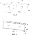
- the two batteries 510 may be placed in parallel in the front-rear direction on the left and right sides of the separator 520 shown in FIG. 6 .
- each battery 510 is provided with a pressure activation piece 511 at a middle position thereof, the pressure activation piece 511 being opposite to the protection device 100 on the separator 520.
- the pressure activation piece 511 and the mounting base 110 may abut against each other or may have a certain gap (e.g., 0.5 mm).
- the first connecting assembly 10 is opposite to one of the two batteries 510 adjacent in the left-right direction
- the second connecting assembly 20 is opposite to the other one of the two batteries 510 adjacent in the left-right direction.
- the protection device 100 between two adjacent batteries 510, when the battery 510 has a safety hazard such as over-charge, short circuit, or over-temperature, the first connecting assembly 10 and the second connecting assembly 20 are driven to be electrically connected with close the overload protection circuit. After the overload protection circuit is closed, the internal circuit of the battery pack 500 may be cut off to prevent the battery pack 500 from being exposed to fires and explosions, thereby improving the safety performance of the battery pack 500.
- a safety hazard such as over-charge, short circuit, or over-temperature
- the protection device 100 is passive protection, thereby improving the reliability of the protection device 100, overcoming the safety hazards of fires and explosions for the battery pack 500 after the failure of the BMS, and the protection device 100 may be used as the second protection after the failure of the BMS.
- the vehicle according to an embodiment of the present disclosure includes the above battery pack 500.
- the first connecting assembly 10 and the second connecting assembly 20 are driven to be electrically connected with close the overload protection circuit.
- an internal circuit of the battery pack 500 may be fused to prevent the battery pack 500 from being exposed to fires and explosions, thereby improving the safety performance of the battery pack 500, and further improving the overall safety of the vehicle.
- references such as reference terms “an embodiment”, “some embodiments”, “example”, “specific example”, or “some examples” intend to indicate that specific features, structures, materials, or characteristics described with reference to embodiments or examples are included in at least one embodiment or example of this disclosure.
- exemplary descriptions of the foregoing terms do not necessarily refer to a same embodiment or example.
- the described specific features, structures, materials, or characteristics may be combined in a proper manner in any one or more of the embodiments or examples.
- a person skilled in the art may integrate or combine different embodiments or examples and characteristics of different embodiments or examples described in the specification, as long as they do not conflict each other.
Landscapes
- Chemical & Material Sciences (AREA)
- Chemical Kinetics & Catalysis (AREA)
- Electrochemistry (AREA)
- General Chemical & Material Sciences (AREA)
- Connection Of Batteries Or Terminals (AREA)
- Battery Mounting, Suspending (AREA)
Abstract
Description
- The present disclosure relates to the technical fields of batteries, and in particular, to a protection device for a battery pack, a battery pack and a vehicle.
- Due to the limited internal space of a vehicle, batteries in a battery pack of the vehicle are densely arranged. When the battery pack of the vehicle is under a high load and works for a long time, it is easy to result in overheating of the batteries. In addition, in the case of over-charge, over-temperature and short circuit of the battery pack, there is also a problem of heat expansion, which may easily cause the battery pack to ignite or even explode. In the related art, a battery module is short-circuit protected and overcharge-protected by a battery management system (BMS) and a fuse (FUSE) system, but it not only is costly, but also cannot achieve short-circuit protection between battery cells. Moreover, the protection mode is active protection, which is low in reliability and relatively poor in versatility.
- An objective of the present disclosure is to at least resolve one of the technical problems in the related art to some extent. In view of this, the present disclosure provides a protection device for a battery pack. The protection device for a battery pack has the advantages of simple structure and good reliability.
- The present disclosure is also directed to a battery pack. The battery pack includes the above protection device.
- The present disclosure also provides a vehicle. The vehicle includes the above battery pack.
- Embodiments of the present disclosure provide a protection device for a battery pack. The battery pack includes a plurality of batteries. The protection device is disposed between two adjacent batteries and includes: a first connecting assembly, the first connecting assembly being opposite to a first battery in the two adjacent batteries, and the first connecting assembly being adapted to be electrically connected with a housing of the first battery; a second connecting assembly, the second connecting assembly being opposite to a second battery in the two adjacent batteries, the second connecting assembly being adapted to be electrically connected with a housing of the second battery, and the second connecting assembly being opposite to the first connecting assembly; and a conductive connecting assembly, the conductive connecting assembly being used for being electrically connected with terminals of the first battery and the second battery, and adapted to be electrically connected with the first connecting assembly and the second connecting assembly, respectively, to be configured as an overload protection circuit. The protection device has a normal state and an alarm state, when the protection device is in the normal state, the first connecting assembly and the second connecting assembly are spaced apart, and the overload protection circuit is open. When the protection device is in the alarm state, the first connecting assembly is electrically connected with the housing of the first battery, the second connecting assembly is electrically connected with the housing of the second battery, at least one of the first connecting assembly and the second connecting assembly moves to be electrically connected with each other, and the overload protection circuit is short-circuited.
- For the protection device for a battery pack according to the embodiments of the present disclosure, by providing the protection device between two adjacent batteries, when the battery has a safety hazard such as over-charge, short circuit, or over-temperature, the first connecting assembly and the second connecting assembly are driven to be electrically connected with each other to close the overload protection circuit. After the overload protection circuit is closed, an internal circuit of the battery pack may be fused to prevent the battery pack from being exposed to fires and explosions, thereby improving the safety performance of the battery pack. Moreover, the protection device has a simple structure, low cost and reliable operation. In addition, the protection device is passive protection, thereby improving the reliability of the protection device, overcoming the safety hazards of fires and explosions for the battery pack after the failure of a battery management system (BMS), and the protection device may be used as the second protection after the failure of the BMS.
- According to some embodiments of the present disclosure, the conductive connecting assembly includes: a connecting piece, the connecting piece having a weakened area that is fused when the protection device is in the alarm state.
- According to some embodiments of the present disclosure, the weakened area has a plurality of through holes spaced apart from one another.
- According to some embodiments of the present disclosure, the thickness of the weakened area on the connecting piece is less than the thickness of the remaining positions on the connecting piece.
- According to some embodiments of the present disclosure, the first connecting assembly and the second connecting assembly each include: a mounting base, the mounting base being provided with a mounting hole; and a contact unit, the contact unit being received in the mounting hole of the mounting base, the contact unit of the first connecting assembly being adapted to be in contact with the contact unit of the second connecting assembly.
- According to some embodiments of the present disclosure, the contact units of the first connecting assembly and the second connecting assembly each include: an elastic member, the elastic member fitting in the mounting hole of the mounting base, a through hole being defined in the elastic member; and a contact portion, the contact portion being movably disposed in the through hole of the elastic member, the contact portion comprising a first end facing the battery opposite to the contact portion and a second end facing away from the battery opposite to the contact portion.
- According to some embodiments of the present disclosure, when the protection device is in the normal state, the first ends of the contact portions of the first connecting assembly and the second connecting assembly extend from the mounting hole of the mounting base respectively, and the second end of the contact portion of the first connecting assembly is spaced apart from the second end of the contact portion of the second connecting assembly; and when the protection device is in the alarm state, the contact portion of the first connecting assembly and the contact portion of the second connecting assembly move toward each other until the second end of the contact portion of the first connecting assembly is in contact with the second end of the contact portion of the second connecting assembly to close the overload protection circuit.
- According to some embodiments of the present disclosure, the first connecting assembly and the second connecting assembly each further include: a temperature relay, the temperature relay being connected with the contact unit.
- According to some embodiments of the present disclosure, the mounting base includes a mounting groove, the mounting groove being communicated with the mounting hole, and the temperature relay being received in the mounting groove.
- According to some embodiments of the present disclosure, the temperature relay is a memory alloy elastic piece or a bi-metal elastic piece.
- According to some embodiments of the present disclosure, the mounting base of the first connecting assembly includes a plurality of assembly holes spaced apart from each other along the circumferential direction of the mounting base; the mounting base of the second connecting assembly includes a plurality of assembly holes spaced apart from each other along the circumferential direction of the mounting base; and the plurality of assembly holes on the first connecting assembly and the plurality of assembly holes on the second connecting assembly are in one-to-one correspondence.
- According to some embodiments of the present disclosure, the protection device further includes a plurality of connecting members, each connecting member respectively passing through and fitting in one assembly hole of the first connecting assembly and one assembly hole of the second connecting assembly corresponding to the assembly hole of the first connecting assembly.
- The battery pack according to embodiments of the present disclosure includes: a plurality of batteries; a separator, the separator being disposed between two adjacent batteries; and a protection device according to the above embodiments of the present disclosure, the protection device being embedded on the separator, a first connecting assembly of the protection device being opposite to a first battery in the two adjacent batteries and being adapted to be electrically connected with a housing of the first battery, a second connecting assembly of the protection device being opposite to a second battery in the two adjacent batteries and being adapted to be electrically connected with a housing of the second battery, and a conductive connecting assembly of the protection device being electrically connected with terminals of the first battery and the second battery.
- For the battery pack according to the embodiments of the present disclosure, by providing the protection device between two adjacent batteries, when the battery has a safety hazard such as over-charge, short circuit, or over-temperature, the first connecting assembly and the second connecting assembly are driven to be electrically connected with close the overload protection circuit. After the overload protection circuit is closed, an internal circuit of the battery pack may be fused to prevent the battery pack from being exposed to fires and explosions, thereby improving the safety performance of the battery pack. In addition, the protection device is passive protection, thereby improving the reliability of the protection device, overcoming the safety hazards of fires and explosions for the battery pack after the failure of a battery management system (BMS), and the protection device may be used as the second protection after the failure of the BMS.
- According to some embodiments of the present disclosure, the housing of each battery is provided with a pressure activation piece, the pressure activation piece being opposite to the first connecting assembly or the second connecting assembly, and the pressure activation piece being electrically connected with the housing of the battery. When the protection device is in an alarm state, the pressure activation piece is adapted to push one of the first connecting assembly and the second connecting assembly to move toward the other one, such that the first connecting assembly and the second connecting assembly are electrically connected with each other.
- The vehicle according to an embodiment of the present disclosure includes the battery pack according to the above embodiments of the present disclosure.
- For the vehicle according to the embodiments of the present disclosure, by assembling the above battery pack, when the battery has a safety hazard such as over-charge, short circuit, or over-temperature, the first connecting assembly and the second connecting assembly are driven to be electrically connected with close the overload protection circuit. After the overload protection circuit is closed, an internal circuit of the battery pack may be fused to prevent the battery pack from being exposed to fires and explosions, thereby improving the safety performance of the battery pack, and further improving the overall safety of the vehicle.
-
-
FIG. 1 is a schematic structural view of a battery pack according to an embodiment of the present disclosure; -
FIG. 2 is a schematic structural view of the battery pack shown inFIG. 1 , where a housing of the battery pack is removed; -
FIG. 3 is a partial enlarged view of Part B circled inFIG. 2 ; -
FIG. 4 is a schematic structural view of a connecting piece of a protection device for a battery pack according to an embodiment of the present disclosure; -
FIG. 5 is a partial exploded view of a battery pack in which two batteries arranged in a front-rear direction are shown in an explosive manner according to an embodiment of the present disclosure; -
FIG. 6 is a partial schematic structural view of a battery pack in which two protection devices arranged on a separator of the battery pack in a front-rear direction are shown according to an embodiment of the present disclosure; -
FIG. 7 is a schematic structural view of a protection device for a battery pack in which a first connecting assembly is shown in an explosive manner and a second connecting assembly is shown in a non-explosive manner according to an embodiment of the present disclosure; and -
FIG. 8 is a cross-sectional view of a protection device for a battery pack according to an embodiment of the present disclosure. - Reference numerals of the accompanying drawing:
-
protection device 100, - first connecting
assembly 10, - second connecting
assembly 20, -
mounting base 110, connectingmember 113,temperature relay 114,mounting hole 115,assembly hole 116,mounting groove 117, -
contact unit 120,elastic member 121,contact portion 122,first end 1221 ofcontact portion 122,second end 1222 ofcontact portion 122, - conductive connecting
assembly 30, connectingpiece 310, weakenedarea 311, throughhole 312,clamping hole 313, connectinghole 314, -
battery pack 500,battery 510,pressure activation piece 511,separator 520,housing 530, andcooling system 540. - The following describes embodiments of the present invention in detail. Examples of the embodiments are shown in the accompanying drawings. The embodiments described below with reference to the accompanying drawings are exemplary, aim to explain the disclosure, but cannot be understood as a limitation on the disclosure.
- In the description of the present disclosure, it should be understood that, orientations or position relationships indicated by terms such as "length", "width", "thickness", "up", "down", "front", "back", "left", "right", "vertical", "horizontal", "top", "bottom", "inner", "outer", and "circumferential" are orientations or position relationship shown based on the accompanying drawings, and are merely used for describing the present disclosure and simplifying the description, rather than indicating or implying that the apparatus or element should have a particular orientation or be constructed and operated in a particular orientation, and therefore, should not be construed as a limitation on the present disclosure.
- In addition, terms "first" and "second" are used only for description purposes, and shall not be understood as indicating or suggesting relative importance or implicitly indicating a quantity of indicated technical features. Therefore, features defined by "first" and "second" may explicitly or implicitly include at least one feature. In the description of the present disclosure, unless otherwise specifically limited, "multiple" means at least two, for example, two or three.
- In the present disclosure, unless otherwise clearly specified and limited, terms "mount", "connected", "connect", and "fix" should be understood in a generalized manner, for example, may be understood as fixed connection, detachable connection, or integration; or may be understood as mechanical connection, electrical connection, or mutual communication; or may be understood as direct connection, or indirect connection by means of a medium, or internal communication of two elements or a mutual relationship between two elements, unless otherwise clearly specified. A person of ordinary skill in the art may understand specific meanings of the foregoing terms in this disclosure according to a specific situation.
- A
protection device 100 for abattery pack 500, abattery pack 500 and a vehicle according to an embodiment of the present disclosure will be described below with reference toFIGS. 1-8 . - As shown in
FIGS. 1-8 , thebattery pack 500 according to an embodiment of the present disclosure includes a plurality ofbatteries 510, theprotection device 100 being disposed between twoadjacent batteries 510. Theprotection device 100 according to an embodiment of the present disclosure includes: a first connectingassembly 10, a second connectingassembly 20 and a conductive connectingassembly 30. Theprotection device 100 for thebattery pack 500 may be applied to a vehicle. - Specifically, as shown in
FIGS. 5-8 , the first connectingassembly 10 is opposite to one of the twoadjacent batteries 510, and the second connectingassembly 20 is opposite to the other one of the twoadjacent batteries 510. That is, the first connecting assembly is opposite to a first battery in two adjacent batteries, and the second connecting assembly is opposite to a second battery in the two adjacent batteries. The second connectingassembly 20 is opposite to the first connectingassembly 10. In other words, the first connectingassembly 10 and the second connectingassembly 20 are disposed opposite to each other between twoadjacent batteries 510. There is a certain gap between the first connectingassembly 10 and the second connecting assembly 20 (e.g., may be 1-1.2 mm), the first connectingassembly 10 and onebattery 510 may have a gap (i.e., 0.5 mm) or abut against each other, and the second connectingassembly 20 and theother battery 510 may also have a gap (i.e., 0.5 mm) or abut against each other. The first connecting assembly is adapted to be electrically connected with a housing of the first battery, the second connecting assembly is adapted to be electrically connected with a housing of the second battery, and the conductive connectingassembly 30 is used for being electrically connected with terminals of the first battery and the second battery, and adapted to be electrically connected with the first connectingassembly 10 and the second connectingassembly 20, respectively, to be configured as an overload protection circuit. - As shown in
FIG. 1 and FIG. 2 , thebattery pack 500 has ahousing 530, and a plurality ofbatteries 510 may be disposed inside thehousing 530. Thebatteries 510 may be arranged in a regular matrix inside thehousing 530 or in other forms. Since the mounting space for thebattery pack 500 in the vehicle is limited, thebatteries 510 in thebattery pack 500 are arranged densely. When thebattery pack 500 is operated under a heavy load, thebattery 510 is prone to heat generation, thereby causing a risk of fire, explosion and the like. However, for theprotection device 100 for thebattery pack 500 according to an embodiment of the present disclosure, theprotection device 100 is disposed between twoadjacent batteries 510, and the first connectingassembly 10 and the second connectingassembly 10 may be disposed opposite to each other between the twoadjacent batteries 510. When thebattery pack 500 has a safety hazard, the first connectingassembly 10 and the second connectingassembly 20 are adapted to be electrically connected with each other to close the overload protection circuit, and the closed overload protection circuit may protect thebattery pack 500. - The
protection device 100 has a normal state and an alarm state. When theprotection device 100 is in the normal state, thebatteries 510 of thebattery pack 500 according to an embodiment of the present disclosure are connected with each other by the conductive connectingassembly 30 to form a charge or discharge loop. The first connectingassembly 10 and the second connectingassembly 20 are spaced apart from each other. That is, the first connectingassembly 10 and the second connectingassembly 20 are disconnected from each other, that is, the overload protection circuit is in a disconnected state. It will be appreciated that theprotection device 100 in the normal state means that thebattery pack 500 is in a stable and safe working state. - When the
protection device 100 is in the alarm state, at least one of the first connectingassembly 10 and the second connectingassembly 20 moves to be electrically connected with each other. At this time, the overload protection circuit is closed. It will be appreciated that theprotection device 100 in the alarm state means that thebattery pack 500 is in an unsafe working state such as over-charge, short circuit and over-temperature. - For example, when the temperature of one of the
batteries 510 in thebattery pack 500 is too high, thebattery 510 is thermally expanded, and the housing of the expandedbattery 510 extrudes theprotection device 100 between thebattery 510 and abattery 510 adjacent thereto, so that the housing of the expandedbattery 510 is electrically connected with the first connectingassembly 10 or the second connectingassembly 20, and the first connectingassembly 10 or the second connectingassembly 20 is allowed to move, whereby the first connectingassembly 10 is in contact with the second connectingassembly 20 to form an electrical connection therebetween. That is, the first connectingassembly 10 and the second connectingassembly 20 are electrically connected with the housing of one of the adjacent batteries respectively, and at least one of the first connectingassembly 10 and the second connectingassembly 20 moves to be electrically connected with each other. The adjacent batteries are electrically connected by the conductive connectingassembly 30, and the short circuit of cells is achieved by the polarity of the housings of the adjacent batteries. - For example, in general, the housing of the battery has the same polarity as a negative electrode of the battery, and if the conductive connecting
assembly 30 is connected with a positive terminal of the first battery and a negative terminal of the second battery in the adjacent batteries, so that the adjacent batteries are connected in series. When theprotection device 100 is in the alarm state, the first connectingassembly 10 is electrically connected with the housing of the first battery, the second connectingassembly 20 is electrically connected with the housing of the second battery, and the first connectingassembly 10 and the second connectingassembly 20 are electrically connected with each other. That is, when theprotection device 100 is in the alarm state, the negative electrodes of the first battery and the second battery are directly electrically connected. At this time, the positive terminal of the first battery is electrically connected with a negative housing of the first battery through the conductive connectingassembly 30, the negative terminal of the second battery, and the second connecting assembly 20 (having the same polarity as the negative terminal of the second battery) and the first connectingassembly 10 sequentially, that is, a short circuit is formed between the positive and negative electrodes of the first battery, a large current is generated, and then the conductive connectingassembly 30 is fused. At this time, the overload protection circuit may be closed and an internal circuit of thebattery pack 500 may be fused, and an abnormal battery (i.e., an expanded or bulged battery) is thus disconnected from a charge or discharge circuit to prevent thebattery pack 500 from being exposed to fires and explosions, thereby improving the safety performance of thebattery pack 500. - For the
protection device 100 for thebattery pack 500 according to an embodiment of the present disclosure, by providing theprotection device 100 between twoadjacent batteries 510, when thebattery 510 has a safety hazard such as over-charge, short circuit, or over-temperature, the first connectingassembly 10 and the second connectingassembly 20 are electrically connected with close the overload protection circuit. After the overload protection circuit is closed, the internal circuit of thebattery pack 500 may be fused to prevent thebattery pack 500 from being exposed to fires and explosions, thereby improving the safety performance of thebattery pack 500. Moreover, theprotection device 100 has a simple structure, low cost and reliable operation. In addition, theprotection device 100 is passive protection, thereby improving the reliability of theprotection device 100, overcoming the safety hazards of fires and explosions for thebattery pack 500 after the failure of a battery management system (BMS), and theprotection device 100 may be used as the second protection after the failure of the BMS. - According to one embodiment of the present disclosure, as shown in
FIGS. 2-4 , the conductive connectingassembly 30 includes a connectingpiece 310. The connectingpiece 310 has a weakenedarea 311. When theprotection device 100 is in the alarm state, the weakenedarea 311 is fused. In some embodiments, the weakenedarea 311 may perform matching design according to different capacities and types of thebattery 510. For example, the weakenedarea 311 may be designed such that when a current of 600 A flows through the weakenedarea 311, the weakenedarea 311 is fused within 10S. After the weakenedarea 311 is fused, the internal circuit of thebattery pack 500 is cut off, thus protecting thebattery pack 500. - Further, the weakened
area 311 may be provided with a plurality of throughholes 312 spaced apart. For example, as shown in the example ofFIG. 4 , the connectingpiece 310 has a symmetrical structure, along the length direction of the connecting piece 310 (i.e., left-right direction inFIG. 4 ), the connectingpiece 310 is provided with a weakenedarea 311 at a middle position thereof, the weakenedarea 311 protrudes upward to form a bridge portion, and the weakenedarea 311 is provided with a plurality of throughholes 312 spaced apart. In some embodiments of the present disclosure, as the thickness of the weakened area 311 (i.e., dimension in an up-down direction shown inFIG. 4 ) is smaller, the width (i.e., dimension in a front-rear direction shown inFIG. 4 ) is smaller. As the capability of current carrying of the weakenedarea 311 is weaker, the weakenedarea 311 may be fused at a low current within a short time. Thus, according to the capacity and type of thebattery 510, by providing a plurality of throughholes 312 in the weakenedarea 311 and adjusting the size of the weakenedarea 311, the over-charge, over-temperature and short-circuit protection requirements for different battery packs 500 can be satisfied. - In some embodiments of the present disclosure, the thickness of the weakened
area 311 on the connectingpiece 310 may be less than the thickness of the remaining positions on the connectingpiece 310. As shown inFIG. 4 , the thickness (i.e., dimension in an up-down direction shown inFIG. 4 ) of the weakenedarea 311 at the middle of the connectingpiece 310 is less than the thickness (i.e., dimension in an up-down direction shown inFIG. 4 ) of the remaining positions on the connectingpiece 310. It will be appreciated that, as shown inFIG. 4 , the weakenedarea 311 at the middle position of the connectingpiece 310 protrudes upward, and the thickness of the weakenedarea 311 is small, so that when thebattery pack 500 has a safety hazard, the weakenedarea 311 can be fused in time, the internal circuit of thebattery pack 500 can be cut off, and thebattery pack 500 can be protected. Since the connectingpiece 310 needs to be fixed to thepartition 520, each end of the connectingpiece 310 is provided with aclamping hole 313 and a connectinghole 314 to facilitate the fixed assembly of the connectingpiece 310. The thickness of the left and right ends of the connectingpiece 310 is large to ensure the structural strength of the connectingpiece 310, and to prevent breakage when the connectingpiece 310 is fixed, thereby enhancing the fixing reliability and stability of the connectingpiece 310. - According to some embodiments of the present disclosure, as shown in
FIGS. 7 and 8 , the first connectingassembly 10 and the second connectingassembly 10 have the same structure, and thus the first connectingassembly 10 is taken as an example to describe the structure of the first connectingassembly 10 and the second connectingassembly 20. As shown inFIG. 7 , the first connectingassembly 10 is shown in an explosive manner, and the first connectingassembly 10 includes a mountingbase 110 and acontact unit 120. Thecontact unit 120 is embedded into the mountingbase 110, thereby facilitating assembly of thecontact unit 120. Thecontact unit 120 of the first connectingassembly 10 is adapted to be in contact with thecontact unit 120 of the second connectingassembly 20, such that the first connectingassembly 10 and the second connectingassembly 20 are electrically connected. Thus, when thebattery pack 500 has a safety hazard such as over-temperature, over-charge and short circuit, the first connectingassembly 10 may be electrically connected with the second connectingassembly 20, thereby closing the overload protection circuit to protect thebattery pack 500. - Further, as shown in
FIGS. 7 and 8 , thecontact unit 120 includes: anelastic member 121 and acontact portion 122. Theelastic member 121 is provided with a through hole. Thecontact portion 122 is movably disposed in the through hole of theelastic member 121. In addition, a mountinghole 115 is provided in the mountingbase 110, and theelastic member 121 with thecontact portion 122 may be received in the mountinghole 115 of the mountingbase 110. In some embodiments of the present disclosure, thecontact portion 122 may be made of metal having a low electrical resistivity, such as red copper. In order to improve the oxidation resistance of thecontact portion 122 and reduce the contact resistance, thecontact portion 122 may be subjected to treatment such as silver plating, gold plating, or nickel plating. - In some embodiments of the present disclosure, the
contact portion 122 includes afirst end 1221 facing thebattery 510 opposite to thecontact portion 122 and asecond end 1222 facing away from the battery 510 (i.e., facing another contact portion 122) opposite to thecontact portion 122. When theprotection device 100 is in the normal state, thefirst end 1221 of thecontact portion 122 extends from the mountinghole 115 of the mountingbase 110 under the action of theelastic member 121, and thesecond end 1222 of thecontact portion 122 is spaced apart from thesecond end 1222 of anothercontact portion 122, thereby preventing accidental contact of the twocontact portions 120. When theprotection device 100 is in the alarm state, thebattery 510 opposite to thecontact portion 122 applies an acting force to thefirst end 1221 of thecontact portion 122 to push thecontact portion 122 toward anothercontact portion 122 against the acting force of theelastic member 121 until the second ends 1222 of the twocontact portions 122 are in contact with each other to close the overload protection circuit. - In some embodiments of the present disclosure, as shown in
FIG. 5 , apressure activation piece 511 may be disposed at a middle position, corresponding to theprotection device 100, of thebattery 510. Thepressure activation piece 511 is electrically connected with the housing of thebattery 510. Thepressure activation piece 511 and the mounting base 110 (specifically, the contact portion 122) may abut against each other or have a small gap (e.g., 0.5 mm). When there is a safety hazard in thebattery pack 500, for example, when the temperature of thebattery 510 is too high, thepressure activation piece 511 located on thebattery 510 is changed from a concave state to a convex state, thereby being in electrical contact with thecontact portion 122 of one connecting assembly to push thecontact portion 122 of this connecting assembly to moved toward thecontact portion 122 of another connecting assembly, and being in electrical contact with thecontact portion 122 of this connecting assembly to close the overload protection circuit, so as to protect thebattery pack 500. - In some embodiments of the present disclosure, the first connecting
assembly 10 may further include atemperature relay 114. Thecontact unit 120 is disposed on thetemperature relay 114. Thetemperature relay 114 and thecontact unit 120 are embedded together on the mountingbase 110. As shown inFIG. 7 , thecontact unit 120 may be disposed on a surface of thetemperature relay 114 facing the mountingbase 110. Accordingly, a mountinggroove 117 may be defined on the mountingbase 110 for receiving thetemperature relay 114. As shown inFIGS. 7 and 8 , thetemperature relay 114 has a rectangular piece shape, and the mountinggroove 117 has a rectangular shape and is provided on the surface of the mountingbase 110 facing away from thebattery 510 opposite thereto. For the first connectingassembly 10, the mountinggroove 117 is provided on a rear surface of the mountingbase 110 of the first connectingassembly 10. For the second connectingassembly 20, the mountinggroove 117 is provided on a front surface of the mountingbase 110 of the second connectingassembly 20. In some embodiments of the present disclosure, the depth (i.e., dimension in the front-rear direction shown inFIGS. 7 and 8 ) of the mountinggroove 117 is greater than the thickness (i.e., dimension in the front-rear direction shown inFIGS. 7 and 8 ) of thetemperature relay 114, such that when the first connectingassembly 10 and the second connectingassembly 20 are mounted in position, the distance between thecontact unit 120 of the first connectingassembly 10 and thecontact unit 120 of the second connectingassembly 20 is 1-1.2 mm. In addition, the mountinggroove 117 is communicated with the mountinghole 115 such that thetemperature relay 114 and thecontact unit 120, assembled together, may be embedded together into the mountingbase 110. - The
temperature relay 114 may be deformed according to a temperature change, so that the twocontact units 120 opposite to each other may be driven to close the overload protection circuit. When theprotection device 100 is in the normal state, thetemperature relay 114 is not deformed, thefirst end 1221 of thecontact portion 122 extends from the mountinghole 115 of the mountingbase 110 under the action of theelastic member 121, and thesecond end 1222 of thecontact portion 122 is spaced apart from thesecond end 1222 of anothercontact portion 122, thereby preventing accidental contact of the twocontact portions 120. When theprotection device 100 is in the alarm state, for example, when the temperature of thebattery 510 is too high, exceeding a critical temperature (e.g., 80°C) of thetemperature relay 114, thetemperature relay 114 of the first connectingassembly 10 is bent toward thetemperature relay 114 of the second connecting assembly 20 (i.e., backward as shown inFIG. 8 ) to resist the acting force of theelastic member 121 to urge thecontact portion 122 of the first connectingassembly 10 to move toward thecontact portion 122 of the second connecting assembly 20 (i.e., backward as shown inFIG. 8 ). Meanwhile, thetemperature relay 114 of the second connectingassembly 20 may also be bent toward thetemperature relay 114 of the first connecting assembly 10 (i.e., forward as shown inFIG. 8 ) to resist the acting force of theelastic member 121 to urge thecontact portion 122 to move (i.e., forward as shown inFIG. 8 ), such that thecontact portion 122 of the first connectingassembly 10 is in contact with thecontact portion 122 of the second connectingassembly 20 to close the overload protection circuit. Thus, the weakenedarea 311 of the connectingpiece 310 is fused, thereby cutting off the internal circuit of thebattery pack 500, achieving over-temperature protection of thebattery pack 500, and making thebattery pack 500 operate more stably and reliably. To ensure the normal operation of thetemperature relay 114, thetemperature relay 114 may be fixed in the mountinggroove 117 at the circumferential edge thereof, that is, the circumferential edge of thetemperature relay 114 cannot move, while a central region of thetemperature relay 114 may still be backward or may protrude backward, that is, the deformation occurs. - In some embodiments of the present disclosure, the
temperature relay 114 may be a memory alloy elastic piece or a bi-metal elastic piece. However, the present disclosure is not limited to this. For example, thetemperature relay 114 may also be other temperature relays. In actual production, thetemperature relay 114 may be selected accordingly according to the temperature protection range of thebattery pack 500 to accurately and reliably achieve over-temperature protection of thebattery pack 500. - In a specific embodiment of the present disclosure, the mounting
base 110 may be in the shape of a disk and provided with a cylindrical mountinghole 115 at its center. Theelastic member 121 and thecontact portion 122 are both cylindrical, and thecontact portion 122 is disposed in the cylindrical through hole on theelastic member 121. The mountingbase 110 may also be provided with anassembly hole 116. As shown inFIG. 7 , a plurality of assembly holes 116 are spaced apart in the circumferential direction of the mountingbase 110 of the first connectingassembly 10, and a plurality of assembly holes 116 are also spaced apart in the circumferential direction of the mountingbase 110 of the second connectingassembly 20. The assembly holes 116 in the mountingbase 110 of the first connectingassembly 10 are in one-to-one correspondence with the assembly holes 116 in the mountingbase 110 of the second connectingassembly 20. Theprotection device 100 further includes connectingmembers 113. Each connectingmember 113 respectively passes through and fits in theassembly hole 116 in the mountingbase 110 of the first connectingassembly 10 and thecorresponding assembly hole 116 in the mountingbase 110 of the second connectingassembly 20, so as to achieve a stable assembly between the first connectingassembly 10 and the second connectingassembly 20. - In some embodiments of the present disclosure, the connecting
member 113 may be a columnar pin, and theassembly hole 116 may be a cylindrical through hole. As shown inFIG. 7 , theprotection device 100 includes fourcolumnar pins 113. Correspondingly, four cylindrical throughholes 116 are spaced apart in the circumferential direction of the mountingbase 110 of the first connectingassembly 10, and four cylindrical throughholes 116 are spaced apart in the circumferential direction of the mountingbase 110 of the second connectingassembly 20. Thus, the first connectingassembly 10 and the second connectingassembly 20 may be assembled together conveniently and efficiently by the fit between the columnar pins and the cylindrical through holes. - In some embodiments of the present disclosure, the
protection device 100 for thebattery pack 500 may further include a negative temperature coefficient (NTC) temperature sensor and a battery management system (BMS). The NTC temperature sensor consists of an NTC thermistor and a probe, and the resistance value thereof drops rapidly as the temperature rises. Thus, the corresponding temperature can be determined by measuring the resistance value of the NTC temperature sensor, thereby achieving the purpose of detecting and controlling the temperature. The NTC temperature sensor is distributed on the connectingpiece 310. The BMS may collect and analyze temperature data to start and stop acooling system 540 of thebattery pack 500. Thus, when thebattery pack 500 has a safety hazard during short circuit, over-charge, over-discharge, overload or collision, theprotection device 100 for thebattery pack 500 may perform the following triple protection in sequence. - First protection: the
battery pack 500 is protected by the NTC temperature sensor and the BMS. The BMS collects and analyzes temperature data of thebattery 510 when thebattery 510 has a safety hazard and generates heat. When the temperature of thebattery 510 reaches a certain set value, the BMS activates thecooling system 540, and thecooling system 540 cools thebattery 510 to achieve temperature drop protection for thebattery pack 500. When the BMS or thecooling system 540 fails, the first protection fails and the temperature of thebattery 510 continues to rise. - Second protection: when the first protection fails, the temperature of the
battery 510 continues to rise; when the temperature of thebattery 510 reaches an activation temperature of thetemperature relay 114, thetemperature relay 114 in theprotection device 100 deforms and drives the first connectingassembly 10 to be electrically connected with the second connectingassembly 20 such that a short circuit is made betweenadjacent batteries 510, the connectingpiece 310 is fused, and a main loop current of thebattery pack 500 is cut off. - Third protection: when the first protection and the second protection fail, the temperature of the
battery 510 continues to rise and thebattery 510 is bulged and expanded; before an explosion-proof valve of thebattery pack 500 is activated, thebattery 510 is bulged to extrude thepressure activation piece 511, thepressure activation piece 511 drives the first connectingassembly 10 and the second connectingassembly 20 which are opposite to each other to be electrically connected such that a short circuit is made betweenadjacent batteries 510, the connectingpiece 310 is fused, and a main loop current of thebattery pack 500 is cut off. - Thus, when the
battery pack 500 has a safety hazard, thebattery pack 500 may be triple-protected by theprotection device 100 for thebattery pack 500. When the first protection fails, the second protection may be activated; when both the first protection and the second protection fail, the third protection may be activated, thereby further enhancing the safety of thebattery pack 500. - The
protection device 100 for thebattery pack 500 according to an embodiment of the present disclosure will be described in detail below with reference toFIGS. 1-8 in a specific embodiment. It will be appreciated that the following description is only illustrative and not specifically restrictive to the present disclosure. - As shown in
FIG. 1 and FIG. 2 , thebattery pack 500 is externally provided with ahousing 530. Thebattery pack 500 has a plurality ofbatteries 510. The plurality ofbatteries 510 are arranged in a regular matrix inside thehousing 530, and aprotection device 100 is disposed between twoadjacent batteries 510. - As shown in
FIGS. 3-7 , theprotection device 100 includes: a first connectingassembly 10, a second connectingassembly 20 and a conductive connectingassembly 30. The first connectingassembly 10 and the second connectingassembly 20 are disposed opposite to each other between twoadjacent batteries 510, and there is a certain gap between the first connectingassembly 10 and the second connectingassembly 20. The conductive connectingassembly 30 is electrically connected with the first connectingassembly 10 and the second connectingassembly 20, respectively, to form an overload protection circuit. Thus, when the first connectingassembly 10 and the second connectingassembly 20 are electrically connected, the overload protection circuit may be closed. As shown inFIG. 5 , apressure activation piece 511 is disposed at a middle position, corresponding to theprotection device 100, of thebattery 510. - The
protection device 100 has a normal state and an alarm state. When theprotection device 100 is in the normal state, the first connectingassembly 10 and the second connectingassembly 20 are spaced apart, and the overload protection circuit is disconnected. When theprotection device 100 is in the alarm state, at least one of the first connectingassembly 10 and the second connectingassembly 20 moves to be electrically connected with each other. The overload protection circuit is closed. - As shown in
FIGS. 2-4 , the conductive connectingassembly 30 includes a connectingpiece 310. The connectingpiece 310 is located above the battery pack 500 (as shown in an up-down direction inFIG. 2 ). As shown inFIG. 4 , the connectingpiece 310 has a symmetrical structure, and along a left-right direction of the connecting piece 310 (left-right direction as shown inFIG. 4 ), the connectingpiece 310 is provided with a weakenedarea 311 at a middle position thereof. The weakenedarea 311 protrudes upward to form a bridge portion, and the weakenedarea 311 is provided with a plurality of throughholes 312 spaced apart. The thickness of the weakenedarea 311 on the connectingpiece 310 is less than the thickness of the remaining positions on the connectingpiece 310. When theprotection device 100 is in the alarm state, the weakenedarea 311 is fused. Each end of the connectingpiece 310 is provided with aclamping hole 313 and a connectinghole 314 to facilitate the fixed assembly of the connectingpiece 310. In other words, a left end of the connectingpiece 310 is provided with aclamping hole 313 and a connectinghole 314, and a right end of the connectingpiece 310 is also provided with aclamping hole 313 and a connectinghole 314. Theclamping hole 313 at the left end of the connectingpiece 310 and theclamping hole 313 at the right end of the connectingpiece 310 are symmetrically arranged, and the connectinghole 314 at the left end of the connectingpiece 310 and the connectinghole 314 at the right end of the connectingpiece 310 are symmetrically arranged. - As shown in
FIGS. 7 and 8 , the second connectingassembly 20 is identical in construction to the first connectingassembly 10. Specifically, as shown inFIG. 7 , the first connectingassembly 10 includes: a mountingbase 110 and acontact unit 120. Thecontact unit 120 includes anelastic member 121 and acontact portion 122. Theelastic member 121 is provided with a through hole. Thecontact portion 122 is disposed in the through hole of theelastic member 121. The mountingbase 110 is provided with a mountinghole 115 at the center thereof, and thecontact unit 120 fits in the mountinghole 115. The first connectingassembly 10 further includes atemperature relay 114. Thecontact unit 120 is disposed on thetemperature relay 114. As shown inFIGS. 7 and 8 , in the first connectingassembly 10, thecontact unit 120 is disposed on a front surface of thetemperature relay 114; and in the second connectingassembly 20, thecontact unit 120 is disposed on a rear surface of thetemperature relay 114. Thetemperature relay 114 is a rectangular sheet-shaped bi-metal elastic piece. The mountingbase 110 defines a mountinggroove 117. The mountinggroove 117 is communicated with the mountinghole 115, and the shape of the mountinggroove 117 matches the shape of thetemperature relay 114, whereby thetemperature relay 114 and thecontact unit 120 assembled together may be received in the mountinggroove 117 and the mountinghole 115 respectively. - In addition, the mounting
base 110 has a disk-shaped structure and is provided with fourassembly holes 116 spaced apart from each other in the circumferential direction thereof. Theprotection device 100 further includes four connectingmembers 113 configured as columnar pins. The connectingmember 113 passes through theassembly hole 116 in the mountingbase 110 of the first connectingassembly 10 to fit in theassembly hole 116 in the mountingbase 110 of the second connectingassembly 20, thereby efficiently assembling the first connectingassembly 10 and the second connectingassembly 20 together. - In addition, the
protection device 100 for thebattery pack 500 further includes a negative temperature coefficient (NTC) temperature sensor and a battery management system (BMS). The NTC temperature sensor consists of an NTC thermistor and a probe, and the resistance value thereof drops rapidly as the temperature rises. Thus, the corresponding temperature can be determined by measuring the resistance value of the NTC temperature sensor, thereby achieving the purpose of detecting and controlling the temperature. The NTC temperature sensor is distributed on the connectingpiece 310. The BMS may collect and analyze temperature data to start and stop acooling system 540. Thus, when thebattery pack 500 has a safety hazard during short circuit, over-charge, over-discharge, overload or collision, theprotection device 100 for thebattery pack 500 may perform the following triple protection in sequence. - First protection: the
battery pack 500 is protected by the NTC temperature sensor and the BMS. The BMS collects and analyzes temperature data of thebattery 510 when thebattery 510 has a safety hazard and generates heat. When the temperature of thebattery 510 reaches a certain set value, the BMS activates thecooling system 540, and thecooling system 540 cools thebattery 510 to achieve temperature drop protection for thebattery pack 500. When the BMS or thecooling system 540 fails, the first protection fails and the temperature of thebattery 510 continues to rise. - Second protection: when the first protection fails, the temperature of the
battery 510 continues to rise; when the temperature of thebattery 510 reaches an activation temperature of thetemperature relay 114, thetemperature relay 114 inside theprotection device 100 deforms and drives the first connectingassembly 10 to be electrically connected with the second connectingassembly 20 such that a short circuit is made betweenadjacent batteries 510, the connectingpiece 310 is fused, and a main loop current of thebattery pack 500 is cut off. - Third protection: when the first protection and the second protection fail, the temperature of the
battery 510 continues to rise and thebattery 510 is bulged and expanded; before an explosion-proof valve of thebattery pack 500 is activated, thebattery 510 is bulged to extrude thepressure activation piece 511, thepressure activation piece 511 drives the first connectingassembly 10 and the second connectingassembly 20 which are opposite to each other to be electrically connected such that a short circuit is made betweenadjacent batteries 510, the connectingpiece 310 is fused, and a main loop current of thebattery pack 500 is cut off. - Thus, when the
battery pack 500 has a safety hazard, thebattery pack 500 may be triple-protected by theprotection device 100 for thebattery pack 500. When the first protection fails, the second protection may be activated; when both the first protection and the second protection fail, the third protection may be activated, thereby further enhancing the safety of thebattery pack 500. Moreover, theprotection device 100 is simple in structure, low in cost and reliable in operation. In addition, theprotection device 100 overcomes the safety hazards of fires and explosions for thebattery pack 500 after the failure of the BMS, and enhances the safety performance of thebattery pack 500. - The
battery pack 500 according to an embodiment of the present disclosure, as shown inFIG. 1 and FIG. 2 , includes: a plurality of batteries 210 spaced apart, aseparator 520 and theabove protection device 100. - As shown in
FIG. 6 , theseparator 520 is disposed between twobatteries 510 adjacent in a left-right direction, and theseparator 520 is provided with twoprotection devices 100 in a front-rear direction. It should be noted that the twobatteries 510 may be placed in parallel in the front-rear direction on the left and right sides of theseparator 520 shown inFIG. 6 . Correspondingly, as shown inFIG. 5 , eachbattery 510 is provided with apressure activation piece 511 at a middle position thereof, thepressure activation piece 511 being opposite to theprotection device 100 on theseparator 520. Thepressure activation piece 511 and the mountingbase 110 may abut against each other or may have a certain gap (e.g., 0.5 mm). The first connectingassembly 10 is opposite to one of the twobatteries 510 adjacent in the left-right direction, and the second connectingassembly 20 is opposite to the other one of the twobatteries 510 adjacent in the left-right direction. - For the
battery pack 500 according to an embodiment of the present disclosure, by providing theprotection device 100 between twoadjacent batteries 510, when thebattery 510 has a safety hazard such as over-charge, short circuit, or over-temperature, the first connectingassembly 10 and the second connectingassembly 20 are driven to be electrically connected with close the overload protection circuit. After the overload protection circuit is closed, the internal circuit of thebattery pack 500 may be cut off to prevent thebattery pack 500 from being exposed to fires and explosions, thereby improving the safety performance of thebattery pack 500. In addition, theprotection device 100 is passive protection, thereby improving the reliability of theprotection device 100, overcoming the safety hazards of fires and explosions for thebattery pack 500 after the failure of the BMS, and theprotection device 100 may be used as the second protection after the failure of the BMS. - The vehicle according to an embodiment of the present disclosure includes the
above battery pack 500. - For the vehicle according to an embodiment of the present disclosure, by assembling the
above battery pack 500, when thebattery 510 has a safety hazard such as over-charge, short circuit, or over-temperature, the first connectingassembly 10 and the second connectingassembly 20 are driven to be electrically connected with close the overload protection circuit. After the overload protection circuit is closed, an internal circuit of thebattery pack 500 may be fused to prevent thebattery pack 500 from being exposed to fires and explosions, thereby improving the safety performance of thebattery pack 500, and further improving the overall safety of the vehicle. - In the descriptions of this specification, descriptions such as reference terms "an embodiment", "some embodiments", "example", "specific example", or "some examples" intend to indicate that specific features, structures, materials, or characteristics described with reference to embodiments or examples are included in at least one embodiment or example of this disclosure. In this specification, exemplary descriptions of the foregoing terms do not necessarily refer to a same embodiment or example. In addition, the described specific features, structures, materials, or characteristics may be combined in a proper manner in any one or more of the embodiments or examples. In addition, a person skilled in the art may integrate or combine different embodiments or examples and characteristics of different embodiments or examples described in the specification, as long as they do not conflict each other.
- Although the embodiments of the present disclosure are shown and described above, it can be understood that the foregoing embodiments are exemplary, and should not be construed as limitations to the present disclosure. A person of ordinary skill in the art can make changes, modifications, replacements, and variations to the foregoing embodiments within the scope of the present disclosure.
Claims (15)
- A protection device for a battery pack, the battery pack comprising a plurality of batteries, the protection device being disposed between two adjacent batteries and comprising:a first connecting assembly, the first connecting assembly being opposite to a first battery in the two adjacent batteries, and the first connecting assembly being adapted to be electrically connected with a housing of the first battery;a second connecting assembly, the second connecting assembly being opposite to a second battery in the two adjacent batteries, the second connecting assembly being adapted to be electrically connected with a housing of the second battery, and the second connecting assembly being opposite to the first connecting assembly; anda conductive connecting assembly, the conductive connecting assembly being used for being electrically connected with terminals of the first battery and the second battery, and adapted to be electrically connected with the first connecting assembly and the second connecting assembly, respectively, to be configured as an overload protection circuit, whereinthe protection device has a normal state and an alarm state, when the protection device is in the normal state, the first connecting assembly and the second connecting assembly are spaced apart, and the overload protection circuit is open; andwhen the protection device is in the alarm state, the first connecting assembly is electrically connected with the housing of the first battery, the second connecting assembly is electrically connected with the housing of the second battery, at least one of the first connecting assembly and the second connecting assembly moves to be electrically connected with each other, and the overload protection circuit is closed.
- The protection device according to claim 1, wherein the conductive connecting assembly comprises:
a connecting piece, the connecting piece having a weakened area which is fused when the protection device is in the alarm state. - The protection device according to claim 2, wherein the weakened area has a plurality of through holes spaced apart from one another.
- The protection device according to claim 2 or 3, wherein the thickness of the weakened area on the connecting piece is less than the thickness of the remaining positions on the connecting piece.
- The protection device according to any one of claims 1 to 4, wherein the first connecting assembly and the second connecting assembly each comprise:a mounting base, the mounting base being provided with a mounting hole; anda contact unit, the contact unit being received in the mounting hole of the mounting base,the contact unit of the first connecting assembly being adapted to be in contact with the contact unit of the second connecting assembly.
- The protection device according to claim 5, wherein the contact units of the first connecting assembly and the second connecting assembly each comprise:an elastic member, the elastic member fitting in the mounting hole of the mounting base, a through hole being defined in the elastic member; anda contact portion, the contact portion being movably disposed in the through hole of the elastic member, the contact portion comprising a first end facing the battery opposite to the contact portion and a second end facing away from the battery opposite to the contact portion.
- The protection device according to claim 6, whereinwhen the protection device is in the normal state, the first ends of the contact portions of the first connecting assembly and the second connecting assembly extend from the mounting hole of the mounting base respectively, and the second end of the contact portion of the first connecting assembly is spaced apart from the second end of the contact portion of the second connecting assembly; andwhen the protection device is in the alarm state, the contact portion of the first connecting assembly and the contact portion of the second connecting assembly move toward each other until the second end of the contact portion of the first connecting assembly is in contact with the second end of the contact portion of the second connecting assembly to close the overload protection circuit.
- The protection device according to any one of claims 5 to 7, wherein the first connecting assembly and the second connecting assembly each further comprise: a temperature relay, the temperature relay being connected with the contact unit.
- The protection device according to claim 8, wherein the mounting base comprises a mounting groove, the mounting groove being communicated with the mounting hole, and the temperature relay being received in the mounting groove.
- The protection device according to claim 8 or 9, wherein the temperature relay is a memory alloy elastic piece or a bi-metal elastic piece.
- The protection device according to any one of claims 5 to 10, wherein
the mounting base of the first connecting assembly comprises a plurality of assembly holes spaced apart from each other along the circumferential direction of the mounting base;
the mounting base of the second connecting assembly comprises a plurality of assembly holes spaced apart from each other along the circumferential direction of the mounting base; and
the plurality of assembly holes on the first connecting assembly and the plurality of assembly holes on the second connecting assembly are in one-to-one correspondence. - The protection device according to claim 11, further comprising a plurality of connecting members, each connecting member respectively passing through and fitting in one assembly hole of the first connecting assembly and one assembly hole of the second connecting assembly corresponding to the assembly hole of the first connecting assembly.
- A battery pack, comprising:a plurality of batteries;a separator, the separator being disposed between two adjacent batteries; anda protection device according to any one of claims 1 to 12, the protection device being embedded on the separator, a first connecting assembly of the protection device being opposite to a first battery in the two adjacent batteries and being adapted to be electrically connected with a housing of the first battery, a second connecting assembly of the protection device being opposite to a second battery in the two adjacent batteries and being adapted to be electrically connected with a housing of the second battery, and a conductive connecting assembly of the protection device being electrically connected with terminals of the first battery and the second battery.
- The battery pack according to claim 13, wherein the housing of each battery is provided with a pressure activation piece, the pressure activation piece being opposite to the first connecting assembly or the second connecting assembly, and the pressure activation piece being electrically connected with the housing of the battery; and
when the protection device is in an alarm state, the pressure activation piece is adapted to push one of the first connecting assembly and the second connecting assembly to move toward the other one, such that the first connecting assembly and the second connecting assembly are electrically connected with each other. - A vehicle, comprising a battery pack according to claim 13 or 14.
Applications Claiming Priority (2)
| Application Number | Priority Date | Filing Date | Title |
|---|---|---|---|
| CN201611260035 | 2016-12-30 | ||
| PCT/CN2017/091902 WO2018120732A1 (en) | 2016-12-30 | 2017-07-05 | Protection device used in battery pack, battery pack and vehicle |
Publications (2)
| Publication Number | Publication Date |
|---|---|
| EP3565029A1 true EP3565029A1 (en) | 2019-11-06 |
| EP3565029A4 EP3565029A4 (en) | 2020-11-25 |
Family
ID=60679540
Family Applications (1)
| Application Number | Title | Priority Date | Filing Date |
|---|---|---|---|
| EP17888533.1A Pending EP3565029A4 (en) | 2016-12-30 | 2017-07-05 | Protection device used in battery pack, battery pack and vehicle |
Country Status (4)
| Country | Link |
|---|---|
| US (1) | US11056748B2 (en) |
| EP (1) | EP3565029A4 (en) |
| CN (1) | CN107507952B (en) |
| WO (1) | WO2018120732A1 (en) |
Cited By (3)
| Publication number | Priority date | Publication date | Assignee | Title |
|---|---|---|---|---|
| EP4096012A4 (en) * | 2021-03-31 | 2022-11-30 | Contemporary Amperex Technology Co., Limited | BUS COMPONENT, BATTERY AND ELECTRICAL DEVICE |
| CN116799394A (en) * | 2023-08-29 | 2023-09-22 | 深圳海辰储能控制技术有限公司 | Energy storage devices and electrical equipment |
| EP4243189A4 (en) * | 2020-11-20 | 2024-08-14 | BYD Company Limited | SMART CONNECT SHEET, BATTERY PACK AND VEHICLE |
Families Citing this family (9)
| Publication number | Priority date | Publication date | Assignee | Title |
|---|---|---|---|---|
| CN209104250U (en) * | 2018-11-19 | 2019-07-12 | 宁德时代新能源科技股份有限公司 | battery module |
| CN110299574B (en) * | 2019-05-21 | 2021-11-12 | 重庆交通大学 | Battery overcharge protection device |
| CN113629359A (en) * | 2021-08-02 | 2021-11-09 | 陕西奥林波斯电力能源有限责任公司 | Large battery connecting structure |
| CN114188644A (en) * | 2021-11-16 | 2022-03-15 | 深圳市海洋王照明工程有限公司 | Battery holder and battery module |
| CN114388975B (en) * | 2021-12-16 | 2023-06-09 | 杭州申昊科技股份有限公司 | Battery pack for intelligent inspection robot |
| CN114545849B (en) * | 2022-04-25 | 2022-07-12 | 宝嘉智能科技(南通)有限公司 | Low-fault power supply protection type industrial automatic control system |
| CN116505181B (en) * | 2023-06-13 | 2023-10-31 | 江苏智泰新能源科技有限公司 | Sodium ion battery with protection device |
| CN117154349B (en) * | 2023-11-01 | 2024-01-19 | 成都大学 | New energy battery module convenient to change |
| CN117254220B (en) * | 2023-11-15 | 2024-01-30 | 河南锂动电源有限公司 | Overheat fusing type safe lithium battery pack |
Family Cites Families (18)
| Publication number | Priority date | Publication date | Assignee | Title |
|---|---|---|---|---|
| JPWO2002099922A1 (en) * | 2001-06-05 | 2004-09-24 | 日本電池株式会社 | Battery pack device and power supply device using the same |
| US7601460B2 (en) * | 2003-11-28 | 2009-10-13 | Panasonic Corporation | Prismatic battery and manufacturing method thereof |
| KR100903185B1 (en) * | 2005-05-02 | 2009-06-17 | 주식회사 엘지화학 | Improved medium and large battery packs with improved safety |
| KR101046192B1 (en) | 2007-10-30 | 2011-07-05 | 에스케이이노베이션 주식회사 | Overcharge safety device for secondary battery |
| KR101121757B1 (en) * | 2007-11-07 | 2012-03-23 | 에스케이이노베이션 주식회사 | Safety Apparatus and Protection Method of secondary Battery for Electric Vehicle Using Switch |
| KR101128423B1 (en) * | 2008-04-28 | 2012-03-23 | 에스케이이노베이션 주식회사 | Safety switch of secondary battery for electric vehicle and charge / discharge system of secondary battery for electric vehicle using same |
| KR101072955B1 (en) * | 2009-08-14 | 2011-10-12 | 에스비리모티브 주식회사 | Battery module |
| CN201936935U (en) * | 2010-05-31 | 2011-08-17 | 比亚迪股份有限公司 | Battery spacer, core protecting structure and power battery |
| KR101359310B1 (en) * | 2011-07-25 | 2014-02-07 | 주식회사 엘지화학 | Battery Pack of Improved Safety |
| KR101383167B1 (en) * | 2011-10-20 | 2014-04-10 | 주식회사 엘지화학 | Battery Pack of Improved Safety |
| KR101404712B1 (en) | 2012-01-26 | 2014-06-09 | 주식회사 엘지화학 | Battery Pack of Improved Safety |
| JP2015002113A (en) | 2013-06-17 | 2015-01-05 | 株式会社豊田自動織機 | Power storage module and power storage pack |
| KR20150045737A (en) | 2013-10-21 | 2015-04-29 | 삼성에스디아이 주식회사 | Battery Module |
| KR101735875B1 (en) | 2013-11-20 | 2017-05-15 | 삼성에스디아이 주식회사 | Secondary battery module |
| KR101601379B1 (en) * | 2013-12-24 | 2016-03-08 | 현대자동차주식회사 | Safety unit for overcharge of battery |
| KR101738215B1 (en) * | 2014-06-25 | 2017-05-19 | 에스케이이노베이션 주식회사 | Battery cell assembly and battery module for detecting swelling phenomenon thereof |
| CN204927218U (en) | 2015-08-20 | 2015-12-30 | 武汉标迪电子科技有限公司 | Electric vehicle battery pack aluminum case battery protection fuse |
| CN204946982U (en) | 2015-09-12 | 2016-01-06 | 宁德时代新能源科技有限公司 | Batteries in parallel connection module |
-
2017
- 2017-07-05 US US16/474,828 patent/US11056748B2/en active Active
- 2017-07-05 EP EP17888533.1A patent/EP3565029A4/en active Pending
- 2017-07-05 WO PCT/CN2017/091902 patent/WO2018120732A1/en not_active Ceased
- 2017-07-05 CN CN201710540195.2A patent/CN107507952B/en active Active
Cited By (5)
| Publication number | Priority date | Publication date | Assignee | Title |
|---|---|---|---|---|
| EP4243189A4 (en) * | 2020-11-20 | 2024-08-14 | BYD Company Limited | SMART CONNECT SHEET, BATTERY PACK AND VEHICLE |
| EP4096012A4 (en) * | 2021-03-31 | 2022-11-30 | Contemporary Amperex Technology Co., Limited | BUS COMPONENT, BATTERY AND ELECTRICAL DEVICE |
| US12206138B2 (en) | 2021-03-31 | 2025-01-21 | Contemporary Amperex Technology (Hong Kong) Limited | Bus member, battery and power consumption device |
| CN116799394A (en) * | 2023-08-29 | 2023-09-22 | 深圳海辰储能控制技术有限公司 | Energy storage devices and electrical equipment |
| CN116799394B (en) * | 2023-08-29 | 2023-12-22 | 深圳海辰储能控制技术有限公司 | Energy storage device and electric equipment |
Also Published As
| Publication number | Publication date |
|---|---|
| US20200127252A1 (en) | 2020-04-23 |
| WO2018120732A1 (en) | 2018-07-05 |
| CN107507952B (en) | 2018-11-09 |
| CN107507952A (en) | 2017-12-22 |
| EP3565029A4 (en) | 2020-11-25 |
| US11056748B2 (en) | 2021-07-06 |
Similar Documents
| Publication | Publication Date | Title |
|---|---|---|
| US11056748B2 (en) | Protection device used in battery pack, battery pack and vehicle | |
| US10050315B2 (en) | Battery module with fusible conductors | |
| JP7022349B2 (en) | Electromechanical circuit breaker and battery housing | |
| KR102357835B1 (en) | Battery pack | |
| CN108155429B (en) | Overcharge safety protection device | |
| EP2736092B1 (en) | Battery pack | |
| US6346796B1 (en) | Thermal shut-off device and battery pack | |
| EP3540822B1 (en) | Battery module, and battery pack and automobile including same | |
| CN109565024B (en) | Battery module | |
| KR20140032596A (en) | Battery pack | |
| KR20180091446A (en) | Battery pack and busbar applied for the same | |
| CN102113150A (en) | Middle or large-sized battery pack with improved safety | |
| KR101551036B1 (en) | Apparatus for preventing over charging of battery | |
| CN106068572A (en) | Battery pack | |
| CN216213971U (en) | End cover assembly, power battery and electric device | |
| EP3471172B1 (en) | Disconnectable bus bar for a battery system and battery system including the same | |
| EP4148433B1 (en) | Current measurement device | |
| KR20140116661A (en) | Battery pack | |
| JP2010027263A (en) | Battery module | |
| US11552378B2 (en) | Fusing apparatus | |
| CN111244339A (en) | Battery cover plate and battery with same | |
| KR102074308B1 (en) | Circuit-closing device | |
| JPH1154005A (en) | Current / temperature composite fuse and protection element for secondary battery using the same | |
| CN116417304A (en) | Mechanical controlled fuse | |
| KR20190114374A (en) | Battery module |
Legal Events
| Date | Code | Title | Description |
|---|---|---|---|
| STAA | Information on the status of an ep patent application or granted ep patent |
Free format text: STATUS: THE INTERNATIONAL PUBLICATION HAS BEEN MADE |
|
| PUAI | Public reference made under article 153(3) epc to a published international application that has entered the european phase |
Free format text: ORIGINAL CODE: 0009012 |
|
| STAA | Information on the status of an ep patent application or granted ep patent |
Free format text: STATUS: REQUEST FOR EXAMINATION WAS MADE |
|
| 17P | Request for examination filed |
Effective date: 20190729 |
|
| AK | Designated contracting states |
Kind code of ref document: A1 Designated state(s): AL AT BE BG CH CY CZ DE DK EE ES FI FR GB GR HR HU IE IS IT LI LT LU LV MC MK MT NL NO PL PT RO RS SE SI SK SM TR |
|
| AX | Request for extension of the european patent |
Extension state: BA ME |
|
| DAV | Request for validation of the european patent (deleted) | ||
| DAX | Request for extension of the european patent (deleted) | ||
| A4 | Supplementary search report drawn up and despatched |
Effective date: 20201028 |
|
| RIC1 | Information provided on ipc code assigned before grant |
Ipc: H01M 2/10 20060101ALI20201022BHEP Ipc: H01M 2/34 20060101AFI20201022BHEP |
|
| STAA | Information on the status of an ep patent application or granted ep patent |
Free format text: STATUS: EXAMINATION IS IN PROGRESS |
|
| 17Q | First examination report despatched |
Effective date: 20230511 |