EP3564725A1 - Optical system for curved-screen display - Google Patents
Optical system for curved-screen display Download PDFInfo
- Publication number
- EP3564725A1 EP3564725A1 EP16925918.1A EP16925918A EP3564725A1 EP 3564725 A1 EP3564725 A1 EP 3564725A1 EP 16925918 A EP16925918 A EP 16925918A EP 3564725 A1 EP3564725 A1 EP 3564725A1
- Authority
- EP
- European Patent Office
- Prior art keywords
- optical element
- convex surface
- optical
- surface facing
- optical system
- Prior art date
- Legal status (The legal status is an assumption and is not a legal conclusion. Google has not performed a legal analysis and makes no representation as to the accuracy of the status listed.)
- Withdrawn
Links
- 230000003287 optical effect Effects 0.000 title claims abstract description 189
- 239000000463 material Substances 0.000 claims description 17
- 229910052788 barium Inorganic materials 0.000 claims description 6
- DSAJWYNOEDNPEQ-UHFFFAOYSA-N barium atom Chemical compound [Ba] DSAJWYNOEDNPEQ-UHFFFAOYSA-N 0.000 claims description 6
- 239000005331 crown glasses (windows) Substances 0.000 claims description 4
- 239000005308 flint glass Substances 0.000 claims description 4
- 210000001747 pupil Anatomy 0.000 claims description 4
- 238000010586 diagram Methods 0.000 description 13
- 230000000694 effects Effects 0.000 description 12
- 238000013461 design Methods 0.000 description 6
- 238000012546 transfer Methods 0.000 description 4
- 238000012938 design process Methods 0.000 description 2
- 238000003384 imaging method Methods 0.000 description 2
- 238000012937 correction Methods 0.000 description 1
- 238000000034 method Methods 0.000 description 1
- 238000002156 mixing Methods 0.000 description 1
- 238000012986 modification Methods 0.000 description 1
- 230000004048 modification Effects 0.000 description 1
- 238000006467 substitution reaction Methods 0.000 description 1
Images

Classifications
-
- G—PHYSICS
- G02—OPTICS
- G02B—OPTICAL ELEMENTS, SYSTEMS OR APPARATUS
- G02B9/00—Optical objectives characterised both by the number of the components and their arrangements according to their sign, i.e. + or -
- G02B9/60—Optical objectives characterised both by the number of the components and their arrangements according to their sign, i.e. + or - having five components only
-
- G—PHYSICS
- G02—OPTICS
- G02B—OPTICAL ELEMENTS, SYSTEMS OR APPARATUS
- G02B1/00—Optical elements characterised by the material of which they are made; Optical coatings for optical elements
-
- G—PHYSICS
- G02—OPTICS
- G02B—OPTICAL ELEMENTS, SYSTEMS OR APPARATUS
- G02B13/00—Optical objectives specially designed for the purposes specified below
- G02B13/001—Miniaturised objectives for electronic devices, e.g. portable telephones, webcams, PDAs, small digital cameras
- G02B13/0015—Miniaturised objectives for electronic devices, e.g. portable telephones, webcams, PDAs, small digital cameras characterised by the lens design
- G02B13/002—Miniaturised objectives for electronic devices, e.g. portable telephones, webcams, PDAs, small digital cameras characterised by the lens design having at least one aspherical surface
- G02B13/0045—Miniaturised objectives for electronic devices, e.g. portable telephones, webcams, PDAs, small digital cameras characterised by the lens design having at least one aspherical surface having five or more lenses
-
- G—PHYSICS
- G02—OPTICS
- G02B—OPTICAL ELEMENTS, SYSTEMS OR APPARATUS
- G02B13/00—Optical objectives specially designed for the purposes specified below
- G02B13/001—Miniaturised objectives for electronic devices, e.g. portable telephones, webcams, PDAs, small digital cameras
- G02B13/0055—Miniaturised objectives for electronic devices, e.g. portable telephones, webcams, PDAs, small digital cameras employing a special optical element
- G02B13/006—Miniaturised objectives for electronic devices, e.g. portable telephones, webcams, PDAs, small digital cameras employing a special optical element at least one element being a compound optical element, e.g. cemented elements
-
- G—PHYSICS
- G02—OPTICS
- G02B—OPTICAL ELEMENTS, SYSTEMS OR APPARATUS
- G02B13/00—Optical objectives specially designed for the purposes specified below
- G02B13/08—Anamorphotic objectives
-
- G—PHYSICS
- G02—OPTICS
- G02B—OPTICAL ELEMENTS, SYSTEMS OR APPARATUS
- G02B27/00—Optical systems or apparatus not provided for by any of the groups G02B1/00 - G02B26/00, G02B30/00
- G02B27/01—Head-up displays
- G02B27/017—Head mounted
- G02B27/0172—Head mounted characterised by optical features
Definitions
- the present disclosure relates to a field of optical systems, and more particularly, to an optical system for arc screen display.
- Implementations of the present disclosure provide an optical system capable of presenting arc screen display effect.
- an optical system for arc screen display including:
- an head mounted display device including the optical system for arc screen display described in the first aspect.
- the object in the design is the image in actual application, and the image in the design is the object in actual application; and in the design process, the maximum field at the edge of the optical system is reserved for negative distortion (barrel shape), thus in actual use, it will present a picture with a certain positive distortion (cushion shape), and achieve curved planar imaging effect as well as the arc screen display effect.
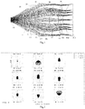
- FIG. 1 illustrates a schematic structure of an optical system for arc screen display according to an embodiment of the present disclosure.
- the optical system shown in Fig.1 was designed under a focal length of 19 nanometers, an entrance pupil diameter of 4 nanometers, and a field angle of 62 degrees.
- the optical system includes a first optical element 10, a second optical element 20, a third optical element 30, a fourth optical element 40, and a fifth optical element 50.
- the first optical element 10, the second optical element 20, the third optical element 30, the fourth optical element 40, and the fifth optical element 50 are all lenses.
- the first optical element 10 includes a first convex surface F1 facing to an object side and a first concave surface F2 facing to an image side.
- the second optical element 20 includes a second concave surface F3 facing to the object side and a second convex surface F4 facing to the image side.
- the third optical element 30 includes a third convex surface F5 facing to the object side and a fourth convex surface F6 facing to the image side.
- the fourth optical element 40 includes a fifth convex surface F7 facing to the object side and a third concave surface F8 facing to the image side.
- the fifth optical element 50 includes a sixth convex surface F9 facing to the object side and a seventh convex surface F10 facing to the image side.
- the first optical element 10, the second optical element 20, the third optical element 30, the fourth optical element 40, and the fifth optical element 50 are sequentially disposed from the object side along a linear optical axis.
- the F0 shown in Fig.1 is an object plane
- the F11 shown in Fig. 1 is an image plane.
- the first convex surface F1, the first concave surface F2, the second concave surface F3, the second convex surface F4, and the third convex surface F5 are all spherical surfaces.
- the fourth convex surface F6, the fifth convex surface F7, the third concave surface F8, the sixth convex surface F9 and the seventh convex surface F10 are all aspherical surfaces.
- the first optical element 10, the third optical element 30, and the fourth optical element 40 are made of barium crown glass (BaK1) materials.
- the second optical element 20 and the fifth optical element 50 are made of dense barium flint glass (ZBaF13) materials.
- Other parameters of the structure of Fig.1 are shown in table 1 and table 2.
- Fig. 2 is a spot diagram of the optical system shown in Fig.1 .
- Fig.3 is an optical transfer function diagram of the optical system shown in Fig.1 .
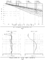
- Fig.4 is a field curvature and distortion diagram of the optical system shown in Fig.1 .
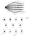
- FIG.5 illustrates a schematic structure of an optical system for arc screen display according to another embodiment of the present disclosure.
- the optical system shown in Fig.5 was designed under a focal length of 12 nanometers, an entrance pupil diameter of 4 nanometers, and a field angle of 66 degrees.
- the optical system includes a first optical element 10, a second optical element 20, a third optical element 30, a fourth optical element 40, and a fifth optical element 50.
- the first optical element 10, the second optical element 20, the third optical element 30, and the fifth optical element 50 are all lenses, and the fourth optical element 40 is a lens unit.
- the first optical element 10 includes a fifth concave surface F1 facing to an object side and an eighth convex surface F2 facing to an image side.
- the second optical element 20 includes a sixth concave surface F3 facing to the object side and a ninth convex surface F4 facing to the image side.
- the third optical element 30 includes a tenth convex surface F5 facing to the object side and an eleventh convex surface F6 facing to the image side.
- the fourth optical element 40 includes a twelfth convex surface F7 facing to the object side, a thirteenth convex surface F8 facing to the image side , a fourteen convex surface F9 facing to the object side, and a seventh concave surface F10 facing to the image side.
- the fifth optical element 50 includes a fifteenth convex surface F11 facing to the object side and an eighth concave surface F12 facing to the image side.
- the first optical element 10, the second optical element 20, the third optical element 30, the fourth optical element 40, and the fifth optical element 50 are sequentially disposed from the object side along an linear optical axis.
- the F0 shown in Fig.5 is an object plane
- the F13 shown in Fig. 5 is an image plane.
- the fifth concave surface F1, the eighth convex surface F2, the sixth concave surface F3, the ninth convex surface F4, the thirteenth convex surface F8, and the fourteenth convex surface F9 are all spherical surfaces.
- the tenth convex surface F5, the eleventh convex surface F6, and the twelfth convex surfaces F7, the seventh concave surface F10, the fifteenth convex surface F11, and the eighth concave surface F12 are all aspherical surfaces.
- the first optical element 10, the second optical element 20, and the third optical element 30 are made of BaK1 materials.
- the fourth optical element 40 is made of BaK1 materials, ZBaF13 materials, and light crown glass (QK3) materials.
- the fifth optical element 50 is made of barium flint glass (BaF3) materials.
- Fig. 6 is a spot diagram of the optical system shown in FIG. 5 .
- FIG. 7 is an optical transfer function diagram of the optical system shown in FIG. 5 .
- FIG. 8 is a field curvature and distortion diagram of the optical system shown in FIG.5 .
- the term "Radius” represents radius of curvature of the surface corresponding to the surface code n.
- the term “Thickness” represents thickness of the lens or interval between the lenses.
- the term “nd” represents refractive index at a line of d.
- the term “vd” represents Abbe number on the line of d.
- the term "surface type” indicates a surface type corresponding to the surface code n, such as spherical surface and aspherical surface.
- the aspherical parameters are shown in the table 2 and the table 4. Where the K, A2, A4, A6 , A8 , A10, A12 and A14 represents aspherical coefficients.
- the optical systems for arc screen display shown in Figs. 1 and 5 all satisfy a condition: -10% ⁇ d ⁇ -5%, and the d is the maximum edge distortion.
- a large screen effect of 18.8 meters multiply 25.9 meters is achieved at a distance of 25 meters, and the maximum edge distortion is -6.2%, which satisfies the above condition.
- a large screen effect of 17.7 meters multiply 24.3 meters is achieved at a distance of 25 meters, and the maximum edge distortion is -8.3%, which satisfies the above condition.
- the optical systems shown in FIG. 1 and FIG. 5 all achieve an arc screen effect, and an overall viewing effect of an arc screen IMAX is realized.
- the illustrated optical system shown in FIG. 1 and FIG. 5 are schematic diagrams in the design of the Zmax software.
- the optical system for arc screen display of the solution provided by the present disclosure reversely processes the actual relationship between an object and an image in the design, that is, the object in the design is the image in actual application, and the image in the design is the object in actual application.
- the maximum field at the edge of the optical system is reserved for negative distortion (barrel shape), thus in actual use, it will present a picture with a certain positive distortion (cushion shape), and achieve curved planar imaging effect as well as the arc screen display effect.
- the embodiment of the disclosure further provides a head mounted display device, where the head mounted display device includes the optical system shown in Figs. 1 and 5 .
Landscapes
- Physics & Mathematics (AREA)
- General Physics & Mathematics (AREA)
- Optics & Photonics (AREA)
- Lenses (AREA)
Abstract
An optical system for a arc-screen display, the system comprising: a first optical element (10), a second optical element (20), a third optical element (30), a fourth optical element (40), and a fifth optical element (50). The optical elements comprise a lens and/or a lens set. The first optical element (10), second optical element (20), third optical element (30), fourth optical element (40), and fifth optical element (50) are arranged in sequence from an object side along a straight optical axis. The optical system for a arc-screen display meets the condition: -10%≤d≤-5%, and d is a maximum edge distortion. The optical system for a arc-screen display of the present disclosure enables display on a arc screen.
Description
- The present disclosure relates to a field of optical systems, and more particularly, to an optical system for arc screen display.
- Traditional arc screen cinemas are perfect for arc screen displays through curtain materials and shapes, multiple projectors, and very complex systems, such as multichannel movie playback systems, and surface correction and edge blending systems. Users who want to watch movies with arc screen effect need to go to cinemas to watch. In order to facilitate the user to watch movies with arc screen effect, it is necessary to provide an optical system capable of presenting arc screen display effect.
- Implementations of the present disclosure provide an optical system capable of presenting arc screen display effect.
- In a first aspect, an optical system for arc screen display is provided in present disclosure, including:
- A first optical element, a second optical element, a third optical element, a fourth optical element, and a fifth optical element;
- Wherein each of the first optical element, the second optical element, the third optical element, the fourth optical element, and the fifth optical element comprises a lens and/or a lens unit;
- Wherein the first optical element, the second optical element, the third optical element, the fourth optical element, and the fifth optical element are sequentially disposed from the object side along a linear optical axis; and
- Wherein the optical system satisfies a condition: -10%≤d≤-5%, and the d is the maximum edge distortion.
- In a second aspect, an head mounted display device is provided in present disclosure, including the optical system for arc screen display described in the first aspect.
- In the optical system for arc screen display of the solution provided by the present disclosure, the object in the design is the image in actual application, and the image in the design is the object in actual application; and in the design process, the maximum field at the edge of the optical system is reserved for negative distortion (barrel shape), thus in actual use, it will present a picture with a certain positive distortion (cushion shape), and achieve curved planar imaging effect as well as the arc screen display effect.
- These aspects and other aspects of the present disclosure will be more clearly in the following description of embodiments.
- In order to more clearly explain the technical solutions in the embodiments of the present disclosure or in the prior art, drawings that need to be used in the embodiments or in the prior art will be briefly introduced below. Obviously, the drawings in the following description are only some embodiments of the present disclosure. For those skilled in the art, other drawings can be obtained without paying creative work.
-
Fig.1 is a schematic structure of an optical system for arc screen display according to an implementation of the present disclosure. -
Fig.2 is a spot diagram of the optical system inFig.1 . -
Fig.3 is an optical transfer function diagram of the optical system inFig.1 . -
Fig.4 is a field curvature and distortion diagram of the optical system inFig.1 . -
Fig.5 is a schematic structure of an optical system for arc screen display according to another implementation of the present disclosure. -
Fig.6 is a spot diagram of the optical system inFig.5 . -
Fig.7 is an optical transfer function diagram of the optical system inFig.5 . -
Fig.8 is a field curvature and distortion diagram of the optical system inFig.5 . - In order to enable those skilled in the art to better understand the solution of the present disclosure, the technical solution in the embodiment of the present disclosure will be described clearly and completely below with reference to the drawings in the embodiment of the present disclosure. Obviously, the described embodiment is only a part of the embodiment of the present disclosure, not all of the embodiments. Based on the embodiments of the present disclosure, all other embodiments obtained by those skilled in the art without creative work are within the scope of the present disclosure.
- The details are described below separately.
- The terms "first", "second", "third", and "fourth" and the like in the specification, claims and drawings of the present disclosure are used to distinguish different objects, and are not intended to describe a specific order.
- Referring to
FIG. 1, FIG. 1 illustrates a schematic structure of an optical system for arc screen display according to an embodiment of the present disclosure. The optical system shown inFig.1 was designed under a focal length of 19 nanometers, an entrance pupil diameter of 4 nanometers, and a field angle of 62 degrees. The optical system includes a firstoptical element 10, a secondoptical element 20, a thirdoptical element 30, a fourthoptical element 40, and a fifthoptical element 50. The firstoptical element 10, the secondoptical element 20, the thirdoptical element 30, the fourthoptical element 40, and the fifthoptical element 50 are all lenses. The firstoptical element 10 includes a first convex surface F1 facing to an object side and a first concave surface F2 facing to an image side. The secondoptical element 20 includes a second concave surface F3 facing to the object side and a second convex surface F4 facing to the image side. The thirdoptical element 30 includes a third convex surface F5 facing to the object side and a fourth convex surface F6 facing to the image side. The fourthoptical element 40 includes a fifth convex surface F7 facing to the object side and a third concave surface F8 facing to the image side. The fifthoptical element 50 includes a sixth convex surface F9 facing to the object side and a seventh convex surface F10 facing to the image side. The firstoptical element 10, the secondoptical element 20, the thirdoptical element 30, the fourthoptical element 40, and the fifthoptical element 50 are sequentially disposed from the object side along a linear optical axis. In addition, the F0 shown inFig.1 is an object plane, and the F11 shown inFig. 1 is an image plane. - The first convex surface F1, the first concave surface F2, the second concave surface F3, the second convex surface F4, and the third convex surface F5 are all spherical surfaces. The fourth convex surface F6, the fifth convex surface F7, the third concave surface F8, the sixth convex surface F9 and the seventh convex surface F10 are all aspherical surfaces.
- The first
optical element 10, the thirdoptical element 30, and the fourthoptical element 40 are made of barium crown glass (BaK1) materials. The secondoptical element 20 and the fifthoptical element 50 are made of dense barium flint glass (ZBaF13) materials. Other parameters of the structure ofFig.1 are shown in table 1 and table 2.Fig. 2 is a spot diagram of the optical system shown inFig.1 .Fig.3 is an optical transfer function diagram of the optical system shown inFig.1 .Fig.4 is a field curvature and distortion diagram of the optical system shown inFig.1 .table 1 Surface surface type Raduis(mm) Thickness(mm) Material nd vd F0 infinite 13∼15 F1 spheric 24.7 4.5 1.53 56 F2 spheric 683 6.1 F3 spheric -14.6 2.7 1.64 23 F4 spheric -57.3 0.2 F5 spheric 1.33E+02 10.5 1.53 56 F6 aspheric -31 0.1 F7 aspheric 10.5 8.5 1.53 56 F8 aspheric 51.2 1.9 F9 aspheric 20.3 2.5 1.64 23 F10 aspheric 20.4 9.6 F11 infinite table 2 Surface K A2 A4 A6 A8 A10 A12 A14 F6 -1.1E+00 0.0E+00 5.0E-04 5.8E-06 -3.6E-08 1.3E-10 -2.5E-13 2.0E-16 F7 -5.5E+00 0.0E+00 1.0E-04 -4.1E-06 5.1E-08 -3.1E-10 9.6E-13 -1.2E-15 F8 2.0E-01 0.0E+00 3.0E-04 -4.0E-06 -4.0E-09 2.9E-10 -1.6E-12 2.6E-15 F9 -4.5E+20 0.0E+00 5.0E-04 -5.5E-06 -1.6E-08 5.5E-10 -3.0E-12 5.3E-15 F10 1.0E-01 0.0E+00 1.0E-03 -2.4E-05 2.6E-07 -1.5E-09 4.4E-12 -5.1E-15 - Referring to
FIG.5, FIG.5 illustrates a schematic structure of an optical system for arc screen display according to another embodiment of the present disclosure. The optical system shown inFig.5 was designed under a focal length of 12 nanometers, an entrance pupil diameter of 4 nanometers, and a field angle of 66 degrees. The optical system includes a firstoptical element 10, a secondoptical element 20, a thirdoptical element 30, a fourthoptical element 40, and a fifthoptical element 50. The firstoptical element 10, the secondoptical element 20, the thirdoptical element 30, and the fifthoptical element 50 are all lenses, and the fourthoptical element 40 is a lens unit. The firstoptical element 10 includes a fifth concave surface F1 facing to an object side and an eighth convex surface F2 facing to an image side. The secondoptical element 20 includes a sixth concave surface F3 facing to the object side and a ninth convex surface F4 facing to the image side. The thirdoptical element 30 includes a tenth convex surface F5 facing to the object side and an eleventh convex surface F6 facing to the image side. The fourthoptical element 40 includes a twelfth convex surface F7 facing to the object side, a thirteenth convex surface F8 facing to the image side , a fourteen convex surface F9 facing to the object side, and a seventh concave surface F10 facing to the image side. The fifthoptical element 50 includes a fifteenth convex surface F11 facing to the object side and an eighth concave surface F12 facing to the image side. The firstoptical element 10, the secondoptical element 20, the thirdoptical element 30, the fourthoptical element 40, and the fifthoptical element 50 are sequentially disposed from the object side along an linear optical axis. In addition, the F0 shown inFig.5 is an object plane, and the F13 shown inFig. 5 is an image plane. - The fifth concave surface F1, the eighth convex surface F2, the sixth concave surface F3, the ninth convex surface F4, the thirteenth convex surface F8, and the fourteenth convex surface F9 are all spherical surfaces. The tenth convex surface F5, the eleventh convex surface F6, and the twelfth convex surfaces F7, the seventh concave surface F10, the fifteenth convex surface F11, and the eighth concave surface F12 are all aspherical surfaces.
- Where, the first
optical element 10, the secondoptical element 20, and the thirdoptical element 30 are made of BaK1 materials. The fourthoptical element 40 is made of BaK1 materials, ZBaF13 materials, and light crown glass (QK3) materials. The fifthoptical element 50 is made of barium flint glass (BaF3) materials. - Where, other parameters of the optical system in
FIG. 5 are shown in table 3 and table 4.Fig. 6 is a spot diagram of the optical system shown inFIG. 5 .FIG. 7 is an optical transfer function diagram of the optical system shown inFIG. 5 .FIG. 8 is a field curvature and distortion diagram of the optical system shown inFIG.5 .table 3 Surface surface type Raduis(mm) Thickness(mm) Material nd vd F0 infinite 13∼15 F1 spheric -10 3 1.53 56 F2 spheric -12 0.2 F3 spheric -14.5 5 1.53 56 F4 spheric -15.1 0.2 F5 aspheric 2.17E+01 11 1.53 56 F6 aspheric -95.7 0.2 F7 aspheric 32.8 8.8 1.53 56 F8 spheric -75.1 1.5 1.64 23 F9 spheric 14.5 7 1.49 57 F10 aspheric 103.5 2.1 F11 aspheric 7.9 4.8 1.58 30 F12 aspheric -8.1 5.9 F13 infinite table 4 Surface K A2 A4 A6 A8 A10 F5 -3.1E+00 0.0E+00 3.0E-05 -1.6E-07 6.4E-10 -8.0E-13 F6 8.8E+00 0.0E+00 -9.7E-05 6.7E-07 -1.5E-09 1.1E-12 F7 1.8E+00 1.0E-04 8.8E-07 2.0E-09 1.3E-12 F10 1.1E+00 0.0E+00 3.0E-05 2.7E-06 -3.2E-08 1.2E-10 F11 -1.6E+37 5.0E-04 -5.1E-06 1.6E-08 -8.6E-12 F12 -1.3E+39 0.0E+00 1.0E-03 -1.3E-05 6.5E-08 -1.1E-10 - In the table 1 and the table 3, the term "Radius" represents radius of curvature of the surface corresponding to the surface code n. The term "Thickness" represents thickness of the lens or interval between the lenses. The term "nd" represents refractive index at a line of d. The term "vd" represents Abbe number on the line of d. The term "surface type" indicates a surface type corresponding to the surface code n, such as spherical surface and aspherical surface. The aspherical parameters are shown in the table 2 and the table 4. Where the K, A2, A4, A6 , A8 , A10, A12 and A14 represents aspherical coefficients.
- The optical systems for arc screen display shown in
Figs. 1 and5 all satisfy a condition: -10%≤d≤-5%, and the d is the maximum edge distortion. Using the optical system shown inFig. 1 , a large screen effect of 18.8 meters multiply 25.9 meters is achieved at a distance of 25 meters, and the maximum edge distortion is -6.2%, which satisfies the above condition. Using the optical system shown inFig. 5 , a large screen effect of 17.7 meters multiply 24.3 meters is achieved at a distance of 25 meters, and the maximum edge distortion is -8.3%, which satisfies the above condition. It can be seen that the optical systems shown inFIG. 1 andFIG. 5 all achieve an arc screen effect, and an overall viewing effect of an arc screen IMAX is realized. It should be noted that the illustrated optical system shown inFIG. 1 andFIG. 5 are schematic diagrams in the design of the Zmax software. - It can be seen that the optical system for arc screen display of the solution provided by the present disclosure reversely processes the actual relationship between an object and an image in the design, that is, the object in the design is the image in actual application, and the image in the design is the object in actual application. In the design process, the maximum field at the edge of the optical system is reserved for negative distortion (barrel shape), thus in actual use, it will present a picture with a certain positive distortion (cushion shape), and achieve curved planar imaging effect as well as the arc screen display effect.
- The embodiment of the disclosure further provides a head mounted display device, where the head mounted display device includes the optical system shown in
Figs. 1 and5 . - The above embodiments are only used to illustrate the technical solutions of the present disclosure, and are not intended to be limiting. Although the present disclosure has been described in detail with reference to the above embodiments, those skilled in the art will understand that the technical solutions described in the embodiments can be modified, or some of the technical features can be replaced by equivalents. The modifications or substitutions do not deviate from the scope of the technical solutions of the embodiments of the present disclosure.
Claims (10)
- An optical system for arc screen display, comprising:a first optical element, a second optical element, a third optical element, a fourth optical element, and a fifth optical element;wherein each of the first optical element, the second optical element, the third optical element, the fourth optical element, and the fifth optical element comprises a lens and/or a lens unit;the first optical element, the second optical element, the third optical element, the fourth optical element, and the fifth optical element are sequentially disposed from the object side along a linear optical axis; andthe optical system satisfies a condition: -10%≤d≤-5%, and the d is a maximum edge distortion.
- The optical system of claim 1, wherein when a focal length of the optical system is 19 nanometers, an entrance pupil diameter of the optical system is 4 nanometers, and a field angle of the optical system is 62 degrees, the first optical element, the second optical element, the third optical element, the fourth optical element, and the fifth optical element are all lenses.
- The optical system of claim 2, wherein the first optical element comprises a first convex surface facing to an object side and a first concave surface facing to an image side;
the second optical element comprises a second concave surface facing to the object side and a second convex surface facing to the image side;
the third optical element comprises a third convex surface facing to the object side and a fourth convex surface facing to the image side;
the fourth optical element comprises a fifth convex surface facing to the object side and a third concave surface facing to the image side; and
the fifth optical element comprises a sixth convex surface facing to the object side and a seventh convex surface facing to the image side. - The optical system of claim 3, wherein the first convex surface, the first concave surface, the second concave surface, the second convex surface, and the third convex surface are all spherical surfaces; and
the fourth convex surface, the fifth convex surface, the third concave surface, the sixth convex surface and the seventh convex surface are all aspherical surfaces. - The optical system of any one of claim 2 to claim 4, wherein the first optical element, the third optical element, and the fourth optical element are made of barium crown glass (BaK1) materials; and
the second optical element and the fifth optical element are made of dense barium flint glass (ZBaF13) materials. - The optical system of claim 1, wherein when a focal length of the optical system is 12 nanometers, an entrance pupil diameter of the optical system is 4 nanometers, and a field angle of the optical system is 66 degrees, the first optical element, the second optical element, the third optical element, and the fifth optical element are all lenses, and the fourth optical element is a lens unit.
- The optical system of claim 6, wherein the first optical element comprises a fifth concave surface facing to an object side and an eighth convex surface facing to an image side;
the second optical element comprises a sixth concave surface facing to the object side and a ninth convex surface facing to the image side;
the third optical element comprises a tenth convex surface facing to the object side and an eleventh convex surface facing to the image side;
the fourth optical element comprises a twelfth convex surface facing to the object side, a thirteenth convex surface facing to the image side, a fourteen convex surface facing to the object side, and a seventh concave surface facing to the image side; and
the fifth optical element comprises a fifteenth convex surface facing to the object side and an eighth concave surface facing to the image side. - The optical system of claim 6, wherein the fifth concave surface, the eighth convex surface, the sixth concave surface, the ninth convex surface, the thirteenth convex surface, and the fourteenth convex surface are all spherical surfaces; and
the tenth convex surface, the eleventh convex surface, and the twelfth convex surfaces, the seventh concave surface, the fifteenth convex surface, and the eighth concave surface are all aspherical surfaces. - The optical system of any one of claim 6 to claim 8, wherein the first optical element, the second optical element, and the third optical element are made of BaK1 materials;
the fourth optical element is made of BaK1 materials, ZBaF13 materials, and light crown glass (QK3) materials; and
the fifth optical element is made of barium flint glass (BaF3) materials. - A head mounted display device, comprising the optical system of any one of claim 1 to claim 9.
Applications Claiming Priority (1)
| Application Number | Priority Date | Filing Date | Title |
|---|---|---|---|
| PCT/CN2016/113647 WO2018120080A1 (en) | 2016-12-30 | 2016-12-30 | Optical system for curved-screen display |
Publications (1)
| Publication Number | Publication Date |
|---|---|
| EP3564725A1 true EP3564725A1 (en) | 2019-11-06 |
Family
ID=62138138
Family Applications (1)
| Application Number | Title | Priority Date | Filing Date |
|---|---|---|---|
| EP16925918.1A Withdrawn EP3564725A1 (en) | 2016-12-30 | 2016-12-30 | Optical system for curved-screen display |
Country Status (6)
| Country | Link |
|---|---|
| US (1) | US20200103616A1 (en) |
| EP (1) | EP3564725A1 (en) |
| JP (1) | JP2020513594A (en) |
| KR (1) | KR20190095483A (en) |
| CN (1) | CN108064349A (en) |
| WO (1) | WO2018120080A1 (en) |
Families Citing this family (1)
| Publication number | Priority date | Publication date | Assignee | Title |
|---|---|---|---|---|
| CN118259424B (en) * | 2022-12-27 | 2026-03-10 | 宁波舜宇车载光学技术有限公司 | Optical lens and electronic device |
Family Cites Families (8)
| Publication number | Priority date | Publication date | Assignee | Title |
|---|---|---|---|---|
| JP2005215473A (en) * | 2004-01-30 | 2005-08-11 | Sekinosu Kk | Projection lens device |
| US7095569B2 (en) * | 2004-04-26 | 2006-08-22 | Delphi Technologies, Inc. | Lens system for a motor vehicle vision system |
| CN102109662A (en) * | 2009-12-25 | 2011-06-29 | 佛山普立华科技有限公司 | Imaging lens |
| JP5823258B2 (en) * | 2011-11-02 | 2015-11-25 | 日東光学株式会社 | Projection lens system and projection apparatus |
| CN103823289A (en) * | 2012-11-19 | 2014-05-28 | 上海三鑫科技发展有限公司 | Miniature projection lens |
| CN102998800B (en) * | 2012-12-12 | 2015-06-10 | 中国科学院长春光学精密机械与物理研究所 | Optical system with extra large view field for helmet mounted display (HMD) |
| CN103543515B (en) * | 2013-09-26 | 2015-09-30 | 宁波舜宇红外技术有限公司 | A kind of novel LONG WAVE INFRARED wide-angle lens |
| CN103984084A (en) * | 2014-05-22 | 2014-08-13 | 中山联合光电科技有限公司 | A small volume, small distortion, high pixel optical system |
-
2016
- 2016-12-30 WO PCT/CN2016/113647 patent/WO2018120080A1/en not_active Ceased
- 2016-12-30 KR KR1020197022073A patent/KR20190095483A/en not_active Ceased
- 2016-12-30 US US16/473,146 patent/US20200103616A1/en not_active Abandoned
- 2016-12-30 CN CN201680044939.5A patent/CN108064349A/en not_active Withdrawn
- 2016-12-30 JP JP2019532116A patent/JP2020513594A/en active Pending
- 2016-12-30 EP EP16925918.1A patent/EP3564725A1/en not_active Withdrawn
Also Published As
| Publication number | Publication date |
|---|---|
| US20200103616A1 (en) | 2020-04-02 |
| CN108064349A (en) | 2018-05-22 |
| KR20190095483A (en) | 2019-08-14 |
| JP2020513594A (en) | 2020-05-14 |
| WO2018120080A1 (en) | 2018-07-05 |
Similar Documents
| Publication | Publication Date | Title |
|---|---|---|
| TWI489133B (en) | Image capturing optical system, image capturing device, and portable device | |
| TWI548895B (en) | Image capturing lens system, image capturing apparatus and electronic device | |
| TWI547713B (en) | Imaging optical system, image capturing device, and electronic device | |
| EP2246736B1 (en) | Wide-angle projection lens and portable display device for gaming and other applications | |
| CN103901586B (en) | 3D interactive projection camera lens | |
| TWI585456B (en) | Imaging lens assembly, image capturing apparatus and electronic device | |
| TWI500959B (en) | Photographing optical lens, image capturing device and electronic device | |
| TWI413822B (en) | Lens | |
| CN109445073A (en) | Optical imaging system | |
| TWI443404B (en) | Fixed focus projection lens | |
| CN114859559A (en) | Optical lens | |
| CN107589529B (en) | Head-mounted display device adopting display screen and optical lens system thereof | |
| CN108333721B (en) | Reflection type wide-angle lens | |
| TW201326956A (en) | Image capturing lens system | |
| CN109874302B (en) | Optical system, image magnifying device, virtual reality glasses and augmented reality glasses | |
| CN104142565A (en) | Near-infrared interactive projection lens | |
| CN110824712A (en) | An eyepiece optical system and equipment with a large field of view and high image quality | |
| EP2687888A1 (en) | Anamorphic lens | |
| CN110618524B (en) | Fixed-focus lens and imaging system | |
| CN117761874A (en) | Fixed focus lens | |
| TW201621380A (en) | Imaging lens | |
| WO2021102685A1 (en) | Large-field-of-view high-image-quality eyepiece optical system and device | |
| US20200103616A1 (en) | Optical system for arc display screen | |
| KR101754604B1 (en) | Projection lens unit of projector | |
| CN209148946U (en) | Optical imaging system |
Legal Events
| Date | Code | Title | Description |
|---|---|---|---|
| PUAI | Public reference made under article 153(3) epc to a published international application that has entered the european phase |
Free format text: ORIGINAL CODE: 0009012 |
|
| 17P | Request for examination filed |
Effective date: 20190717 |
|
| AK | Designated contracting states |
Kind code of ref document: A1 Designated state(s): AL AT BE BG CH CY CZ DE DK EE ES FI FR GB GR HR HU IE IS IT LI LT LU LV MC MK MT NL NO PL PT RO RS SE SI SK SM TR |
|
| AX | Request for extension of the european patent |
Extension state: BA ME |
|
| STAA | Information on the status of an ep patent application or granted ep patent |
Free format text: STATUS: THE APPLICATION HAS BEEN WITHDRAWN |
|
| 18W | Application withdrawn |
Effective date: 20191213 |