EP3564698A1 - Method for classifying electromagnetic signals and analysing system - Google Patents
Method for classifying electromagnetic signals and analysing system Download PDFInfo
- Publication number
- EP3564698A1 EP3564698A1 EP18170394.3A EP18170394A EP3564698A1 EP 3564698 A1 EP3564698 A1 EP 3564698A1 EP 18170394 A EP18170394 A EP 18170394A EP 3564698 A1 EP3564698 A1 EP 3564698A1
- Authority
- EP
- European Patent Office
- Prior art keywords
- signal
- measurement signal
- neural network
- machine learning
- electromagnetic
- Prior art date
- Legal status (The legal status is an assumption and is not a legal conclusion. Google has not performed a legal analysis and makes no representation as to the accuracy of the status listed.)
- Granted
Links
Images

Classifications
-
- G—PHYSICS
- G01—MEASURING; TESTING
- G01S—RADIO DIRECTION-FINDING; RADIO NAVIGATION; DETERMINING DISTANCE OR VELOCITY BY USE OF RADIO WAVES; LOCATING OR PRESENCE-DETECTING BY USE OF THE REFLECTION OR RERADIATION OF RADIO WAVES; ANALOGOUS ARRANGEMENTS USING OTHER WAVES
- G01S7/00—Details of systems according to groups G01S13/00, G01S15/00, G01S17/00
- G01S7/02—Details of systems according to groups G01S13/00, G01S15/00, G01S17/00 of systems according to group G01S13/00
- G01S7/021—Auxiliary means for detecting or identifying radar signals or the like, e.g. radar jamming signals
-
- G—PHYSICS
- G01—MEASURING; TESTING
- G01S—RADIO DIRECTION-FINDING; RADIO NAVIGATION; DETERMINING DISTANCE OR VELOCITY BY USE OF RADIO WAVES; LOCATING OR PRESENCE-DETECTING BY USE OF THE REFLECTION OR RERADIATION OF RADIO WAVES; ANALOGOUS ARRANGEMENTS USING OTHER WAVES
- G01S3/00—Direction-finders for determining the direction from which infrasonic, sonic, ultrasonic or electromagnetic waves, or particle emission, not having a directional significance, are being received
- G01S3/02—Direction-finders for determining the direction from which infrasonic, sonic, ultrasonic or electromagnetic waves, or particle emission, not having a directional significance, are being received using radio waves
-
- G—PHYSICS
- G01—MEASURING; TESTING
- G01S—RADIO DIRECTION-FINDING; RADIO NAVIGATION; DETERMINING DISTANCE OR VELOCITY BY USE OF RADIO WAVES; LOCATING OR PRESENCE-DETECTING BY USE OF THE REFLECTION OR RERADIATION OF RADIO WAVES; ANALOGOUS ARRANGEMENTS USING OTHER WAVES
- G01S7/00—Details of systems according to groups G01S13/00, G01S15/00, G01S17/00
- G01S7/02—Details of systems according to groups G01S13/00, G01S15/00, G01S17/00 of systems according to group G01S13/00
- G01S7/41—Details of systems according to groups G01S13/00, G01S15/00, G01S17/00 of systems according to group G01S13/00 using analysis of echo signal for target characterisation; Target signature; Target cross-section
- G01S7/417—Details of systems according to groups G01S13/00, G01S15/00, G01S17/00 of systems according to group G01S13/00 using analysis of echo signal for target characterisation; Target signature; Target cross-section involving the use of neural networks
Definitions
- the invention relates to a method as well as an analysing system for classifying electromagnetic signals.
- the object of the invention therefore is to mitigate influences from error sources on the classification of electromagnetic signals
- the problem is solved by a method for classifying electromagnetic signals, comprising the following steps: an electromagnetic signal is received; a measurement signal is generated from the received electromagnetic signal; the measurement signal is complemented with information missing in the measurement signal and/or perturbations are removed from the measurement signal to provide a modified measurement signal by using at least one machine learning module; and the received electromagnetic signal is classified based on the modified measurement signal.
- the subsequent classification of the electromagnetic signal is greatly simplified and made more reliable.
- the influence of error sources on the classification is effectively mitigated or even eliminated.
- the classification may be done by a machine learning module, in particular by the same machine learning module that complements the measurement signal with the missing information and/or removes perturbations from the measurement signal.
- the electromagnetic signal is a radar-signal.
- the method is used for classifying electromagnetic signals with frequencies within the range suitable for radar applications.
- the information missing may relate to signal portions of the radar-signal.
- the measurement signal comprises one or more pieces of information selected from the group of radio frequency, pulse width, pulse repetition time and direction of arrival. These pieces of information are most suitable for classifying the electromagnetic signal.
- the measurement signal may further comprise information about a time evolution of one or more of these quantities.
- the information added to the measurement signal is selected from the group of radio frequency, pulse width, pulse repetition time and direction of arrival.
- information about two or more of these quantities may be added to the measurement signal.
- missing information with regard to one or more of these pieces of information may be added prior to the classification.
- the at least one machine learning module comprises an artificial neural network system that is used to complement the measurement signal and/or to remove the perturbations from the measurement signal.
- Artificial neural networks are particularly suitable for this kind of operation and enable a fast and reliable complementation of the missing information.
- the neural network system may comprise only one artificial neural network.
- the artificial neural network system may comprise several artificial neural networks.
- the neural network system may be configured to complement the measurement signal and/or to remove the perturbations from the measurement signal by applying pattern recognition techniques to the measurement signal.
- an artificial neural network system is used to classify the received electromagnetic signal.
- the artificial neural network is trained to classify the received electromagnetic signal via pattern recognition methods applied to the modified measurement signal.
- the artificial neural network used to classify the received electromagnetic signal may be the same artificial neural network that complements the measurement signal with the missing information and/or removes perturbations from the measurement signal.
- the artificial neural network system may comprise at least one of an autoencoder, a denoising autoencoder, a generative adversarial network and a recurrent neural network.
- Autoencoders have the advantage that they are suitable for unsupervised machine learning such that a customer may perform the training of the autoencoder on his own.
- Recurrent neural networks are especially suitable for classifying electromagnetic signals with discrete frequency bands that vary over time (“frequency hopper").
- the neural network system is trained with valid and complete signal patterns.
- the artificial neural network system is fed with training signals that resemble real measurement signals but without any information missing.
- the artificial neural network system is enabled to complement the measurement signal with the missing information and/or remove the perturbations from the measurement signal.
- the valid and complete signal patterns are selected from a predetermined set of patterns of electromagnetic signals to be measured.
- the artificial neural network system is fed with training data that corresponds to electromagnetic signals with desired characteristics. This way, the artificial neural network system is efficiently trained to (only) identify electromagnetic signals with specific, predetermined characteristics.
- the neural network system is trained with at least partially labelled data. This means that at least a part of the training data comprises additional information about what kind of measurement signal the training signal corresponds to. Training with at least partially labelled training data may also be referred to as "supervised learning”.
- the neural network system may be trained with unlabelled data.
- unlabelled data is sufficient if, for example, the artificial neural network system comprises an autoencoder or a denoising autoencoder.
- Training with unlabelled training data may also be referred to as "unsupervised learning", which may also be performed by a customer on his own, as no complex data base of electromagnetic signals is needed.
- Whether (partially) labelled or unlabelled training data is used depends on the kind of artificial neural network system and the machine learning method employed.
- an analysing system for classifying electromagnetic signals, in particular for classifying radar-signals.
- the analysing system comprises at least one antenna and at least one classification unit, wherein the antenna is configured to receive an electromagnetic signal to be measured and to forward the electromagnetic signal to the classification unit.
- the classification unit is configured to classify the received electromagnetic signal using a machine learning module, wherein the machine learning module is configured to complement and/or correct the received electromagnetic signal prior to classification of the received electromagnetic signal.
- the machine learning module comprises at least one of an autoencoder, a denoising autoencoder, a generative adversarial network and a recurrent neural network.
- the machine learning module may be trained with valid and complete signal patterns, in particular wherein at least one of the classification and the complementation of the received electromagnetic signal is based on pattern recognition.
- the analysing system is configured to perform the method mentioned above.
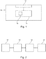
- Figure 1 shows a schematic view of an analysing system 10 for classifying electromagnetic signals, in particular radar signals.
- the analysing system 10 comprises at least one antenna 12 that is configured to receive electromagnetic waves. Accordingly, a receiver is provided.
- Additional antennas may be provided, in particular antennas with main receiving directions that are different from each other and/or adjustable.
- the antenna 12 may be configured to receive electromagnetic waves only in one or more predetermined frequency bands, in particular in frequency bands suitable for radar applications.
- the analysing system 10 further comprises a classification unit 14 that is connected to the antenna 12 in a signal transmitting manner so that signals received by the antenna 12 can be forwarded to the classification unit 14.
- the classification unit 14 is configured to classify the electromagnetic signal received via the at least one antenna 12.
- the classification unit 14 is configured to perform a method for classifying electromagnetic signals, which is described in more detail in the following.
- an electromagnetic signal is received via the antenna 12 and forwarded to the classification unit 14 (step S1).
- the electromagnetic signal may be a radar-signal.
- a measurement signal is generated from the electromagnetic signal (step S2), in particular by the classification unit 14.
- An example for such a measurement signal is depicted in Figure 3 , where the measurement signal is schematically plotted over frequency f and time t.
- the measurement signal comprises at least one of the following pieces of information about the electromagnetic signal: radio frequency (f), pulse width (PW), pulse repetition time (PRT) and direction of arrival.
- the direction of arrival as piece of information may be obtained by the respective main receiving direction of the antenna 12 measuring the respective electromagnetic signal.
- the measurement signal may further comprise information about a time evolution of one or more of these quantities.
- the measurement signal may be represented as a so-called waterfall-diagram as shown in Figure 3 .
- the measurement signal may be incomplete (depicted by the dashed square in Figure 3 ), such that a reliable classification of the electromagnetic signal with conventional methods may be impeded or even hindered.
- the measurement signal may at least partly lack one of the pieces of information mentioned above, i.e. radio frequency, pulse width, pulse repetition time and direction of arrival.
- the measurement signal may comprise perturbations that blanket or rather disturb the signal to be measured.
- perturbations may be interferences, background noise, glitches, or other kinds of distortions of the measurement signal.
- the measurement signal is now complemented with the missing information and/or perturbations are removed from the measurement signal by using at least one machine learning module 16 (step S3), thereby generating a modified measurement signal from the measurement signal.
- the machine learning module 16 may be a microcontroller comprised in the classification unit 14 (indicated by the dashed square in Figure 1 ) and/or a program code block of a program running on the classification unit 14.
- the machine learning module 16 comprises an artificial neural network system that is fed with the measurement signal.
- the artificial neural network system in turn is trained to complement the measurement signal with the missing information and/or to remove the perturbations from the measurement signal.
- the artificial neural network system may be trained to complement the measurement signal by recognising patterns in the measurement signal, in particular patterns with regard to radio frequency, pulse width, pulse repetition time, direction of arrival and/or a time evolution of these quantities.
- the artificial neural network system may comprise an autoencoder, a denoising autoencoder, a generative adversarial network and/or a recurrent neural network being trained to complement the measurement signal and/or remove the perturbations from the measurement signal in the way described above.
- step S3 More details of the procedure of step S3 are depicted in Figure 4 using the example of a (denoising) autoencoder comprising an encoder 18 as well as a decoder 20.
- the encoder 18 is fed with the measurement signal.
- the measurement signal is represented by a noisy input 22 of the number "2".
- the encoder 18 generates a compressed representation 24 from the noisy input 22.
- the compressed representation 24 is then fed to the decoder 20, which generates a denoised output 26 from the compressed representation 24.
- the denoised output 26 corresponds to the modified measurement signal.
- the autoencoder restores information that is missing or at least distorted in the measurement signal to generate the modified measurement signal.
- the electromagnetic signal is classified based on the modified measurement signal (step S4).
- the final classification may be performed via an artificial neural network system, preferably via the artificial neural network system used for generating the modified measurement signal.
- the artificial neural network system may be configured to classify the measurement signal by applying pattern recognition techniques to the modified measurement signal.
- the artificial neural network system is able to reliably complement the measurement signal with missing information, remove perturbations from the measurement signal and/or correctly classify the electromagnetic signal, it has to be trained before usage.
- the artificial neural network system is fed with training signals corresponding to valid and complete electromagnetic signals, in particular the respective signal patterns.
- the training signals correspond to electromagnetic signals that shall be measured and classified with the analysing system 10.
- the training signals may be selected from a predetermined set of signal patterns with regard to radio frequency, pulse width, pulse repetition time, direction of arrival and/or time evolution of these quantities, such that the training signals correspond to electromagnetic signals to be measured during use of the analysing system 10.
- the training signals may at least partially be labelled, i.e. at least a part of the training data comprises additional information about what kind of measurement signal the training signal corresponds to.
- Training with at least partially labelled training data may also be referred to as "supervised learning”.
- the training signals may be unlabelled.
- unlabelled data is sufficient if, for example, the artificial neural network system comprises an autoencoder or a denoising autoencoder.
- Training with unlabelled training data may also be referred to as "unsupervised learning”.
- weighting factors of the artificial neural network system may be adjusted according to any machine learning technique known from the state of the art that is suitable for the artificial neural network(s) comprised in the machine learning module 16.
Landscapes
- Engineering & Computer Science (AREA)
- Radar, Positioning & Navigation (AREA)
- Remote Sensing (AREA)
- Computer Networks & Wireless Communication (AREA)
- Physics & Mathematics (AREA)
- General Physics & Mathematics (AREA)
- Radar Systems Or Details Thereof (AREA)
Abstract
Description
- The invention relates to a method as well as an analysing system for classifying electromagnetic signals.
- In measurements of electromagnetic signals, there are several possible sources of errors. For instance, there are statistical measurement uncertainties that may alter the characteristics of the measured signal. Moreover, there may be methodical uncertainties, e.g. parts of the electromagnetic signal are missed and therefore not measured at all. Moreover, perturbations like background noise or other kinds of distortions may be present.
- All these error sources complicate a classification of the electromagnetic signals. Employing methods known from the state of the art, the classification may even be completely hindered by these error sources.
- The object of the invention therefore is to mitigate influences from error sources on the classification of electromagnetic signals
- According to the invention, the problem is solved by a method for classifying electromagnetic signals, comprising the following steps: an electromagnetic signal is received; a measurement signal is generated from the received electromagnetic signal; the measurement signal is complemented with information missing in the measurement signal and/or perturbations are removed from the measurement signal to provide a modified measurement signal by using at least one machine learning module; and the received electromagnetic signal is classified based on the modified measurement signal.
- The term "perturbations" is to be understood to include interferences, background noise, glitches, or any other kinds of distortions present in the measurement signal.
- The term "complement with information missing in the measurement signal" is to be understood such that information about the signal (e.g. certain characteristics) is added to the measurement signal and/or missing parts of the measurement signal are added.
- By first adding information missing in the measurement signal and/or removing perturbations from the measurement signal, the subsequent classification of the electromagnetic signal is greatly simplified and made more reliable. Thus, the influence of error sources on the classification is effectively mitigated or even eliminated.
- The classification may be done by a machine learning module, in particular by the same machine learning module that complements the measurement signal with the missing information and/or removes perturbations from the measurement signal.
- According to one aspect, the electromagnetic signal is a radar-signal. In other words, the method is used for classifying electromagnetic signals with frequencies within the range suitable for radar applications. The information missing may relate to signal portions of the radar-signal.
- According to another aspect, the measurement signal comprises one or more pieces of information selected from the group of radio frequency, pulse width, pulse repetition time and direction of arrival. These pieces of information are most suitable for classifying the electromagnetic signal.
- The measurement signal may further comprise information about a time evolution of one or more of these quantities.
- In a certain embodiment, the information added to the measurement signal is selected from the group of radio frequency, pulse width, pulse repetition time and direction of arrival. Of course, also information about two or more of these quantities may be added to the measurement signal. Thereby, information that is vital for a correct classification of the electromagnetic signal is added and the reliability of the subsequent classification is greatly enhanced.
- Since information missing may be added prior to the classification, missing information with regard to one or more of these pieces of information may be added prior to the classification.
- In another embodiment of the invention, the at least one machine learning module comprises an artificial neural network system that is used to complement the measurement signal and/or to remove the perturbations from the measurement signal. Artificial neural networks are particularly suitable for this kind of operation and enable a fast and reliable complementation of the missing information.
- Thereby, the neural network system may comprise only one artificial neural network. Alternatively, the artificial neural network system may comprise several artificial neural networks.
- The neural network system may be configured to complement the measurement signal and/or to remove the perturbations from the measurement signal by applying pattern recognition techniques to the measurement signal.
- In particular, an artificial neural network system is used to classify the received electromagnetic signal. Preferably, the artificial neural network is trained to classify the received electromagnetic signal via pattern recognition methods applied to the modified measurement signal.
- The artificial neural network used to classify the received electromagnetic signal may be the same artificial neural network that complements the measurement signal with the missing information and/or removes perturbations from the measurement signal.
- The artificial neural network system may comprise at least one of an autoencoder, a denoising autoencoder, a generative adversarial network and a recurrent neural network. Autoencoders have the advantage that they are suitable for unsupervised machine learning such that a customer may perform the training of the autoencoder on his own. Recurrent neural networks, on the other hand, are especially suitable for classifying electromagnetic signals with discrete frequency bands that vary over time ("frequency hopper").
- According to another aspect, the neural network system is trained with valid and complete signal patterns. In other words, the artificial neural network system is fed with training signals that resemble real measurement signals but without any information missing. In the training procedure, the artificial neural network system is enabled to complement the measurement signal with the missing information and/or remove the perturbations from the measurement signal.
- In another embodiment of the invention, the valid and complete signal patterns are selected from a predetermined set of patterns of electromagnetic signals to be measured. Put another way, the artificial neural network system is fed with training data that corresponds to electromagnetic signals with desired characteristics. This way, the artificial neural network system is efficiently trained to (only) identify electromagnetic signals with specific, predetermined characteristics.
- According to one aspect, the neural network system is trained with at least partially labelled data. This means that at least a part of the training data comprises additional information about what kind of measurement signal the training signal corresponds to. Training with at least partially labelled training data may also be referred to as "supervised learning".
- Alternatively, the neural network system may be trained with unlabelled data. Such unlabelled data is sufficient if, for example, the artificial neural network system comprises an autoencoder or a denoising autoencoder. Training with unlabelled training data may also be referred to as "unsupervised learning", which may also be performed by a customer on his own, as no complex data base of electromagnetic signals is needed.
- Whether (partially) labelled or unlabelled training data is used depends on the kind of artificial neural network system and the machine learning method employed.
- According to the invention, the problem is also solved by an analysing system for classifying electromagnetic signals, in particular for classifying radar-signals. The analysing system comprises at least one antenna and at least one classification unit, wherein the antenna is configured to receive an electromagnetic signal to be measured and to forward the electromagnetic signal to the classification unit. The classification unit is configured to classify the received electromagnetic signal using a machine learning module, wherein the machine learning module is configured to complement and/or correct the received electromagnetic signal prior to classification of the received electromagnetic signal.
- With regards to the advantages of the various embodiments of the analysing system according to the invention, reference is made to the explanations given above regarding the method according to the invention. The same features and advantages also apply for the analysing system.
- In one embodiment, the machine learning module comprises at least one of an autoencoder, a denoising autoencoder, a generative adversarial network and a recurrent neural network.
- The machine learning module may be trained with valid and complete signal patterns, in particular wherein at least one of the classification and the complementation of the received electromagnetic signal is based on pattern recognition.
- In particular, the analysing system is configured to perform the method mentioned above.
- The foregoing aspects and many of the attendant advantages of the claimed subject matter will become more readily appreciated as the same become better understood by reference to the following detailed description, when taken in conjunction with the accompanying drawings, wherein:
-
Figure 1 shows a schematic view of an analyzing system according to the invention; -
Figure 2 shows a schematic flow chart of a method according to the invention; -
Figure 3 shows a diagram of a measurement signal; and -
Figure 4 shows a detailed view of one step of the method ofFigure 2 . - The detailed description set forth below in connection with the appended drawings, where like numerals reference like elements, is intended as a description of various embodiments of the disclosed subject matter and is not intended to represent the only embodiments. Each embodiment described in this disclosure is provided merely as an example or illustration and should not be construed as preferred or advantageous over other embodiments. The illustrative examples provided herein are not intended to be exhaustive or to limit the claimed subject matter to the precise forms disclosed.
-
Figure 1 shows a schematic view of ananalysing system 10 for classifying electromagnetic signals, in particular radar signals. - The analysing
system 10 comprises at least oneantenna 12 that is configured to receive electromagnetic waves. Accordingly, a receiver is provided. - Additional antennas may be provided, in particular antennas with main receiving directions that are different from each other and/or adjustable.
- The
antenna 12 may be configured to receive electromagnetic waves only in one or more predetermined frequency bands, in particular in frequency bands suitable for radar applications. - The analysing
system 10 further comprises aclassification unit 14 that is connected to theantenna 12 in a signal transmitting manner so that signals received by theantenna 12 can be forwarded to theclassification unit 14. - The
classification unit 14 is configured to classify the electromagnetic signal received via the at least oneantenna 12. In particular, theclassification unit 14 is configured to perform a method for classifying electromagnetic signals, which is described in more detail in the following. - First, an electromagnetic signal is received via the
antenna 12 and forwarded to the classification unit 14 (step S1). - In a particular embodiment, the electromagnetic signal may be a radar-signal.
- As a next step, a measurement signal is generated from the electromagnetic signal (step S2), in particular by the
classification unit 14. An example for such a measurement signal is depicted inFigure 3 , where the measurement signal is schematically plotted over frequency f and time t. - The measurement signal comprises at least one of the following pieces of information about the electromagnetic signal: radio frequency (f), pulse width (PW), pulse repetition time (PRT) and direction of arrival.
- The direction of arrival as piece of information may be obtained by the respective main receiving direction of the
antenna 12 measuring the respective electromagnetic signal. - The measurement signal may further comprise information about a time evolution of one or more of these quantities. Thus, the measurement signal may be represented as a so-called waterfall-diagram as shown in
Figure 3 . - Due to measurement uncertainties, missed parts of the electromagnetic signal and/or perturbations during the measurement process, the measurement signal may be incomplete (depicted by the dashed square in
Figure 3 ), such that a reliable classification of the electromagnetic signal with conventional methods may be impeded or even hindered. - For example, the measurement signal may at least partly lack one of the pieces of information mentioned above, i.e. radio frequency, pulse width, pulse repetition time and direction of arrival.
- Moreover, the measurement signal may comprise perturbations that blanket or rather disturb the signal to be measured. Such perturbations may be interferences, background noise, glitches, or other kinds of distortions of the measurement signal.
- Therefore, the measurement signal is now complemented with the missing information and/or perturbations are removed from the measurement signal by using at least one machine learning module 16 (step S3), thereby generating a modified measurement signal from the measurement signal.
- The
machine learning module 16 may be a microcontroller comprised in the classification unit 14 (indicated by the dashed square inFigure 1 ) and/or a program code block of a program running on theclassification unit 14. - The
machine learning module 16 comprises an artificial neural network system that is fed with the measurement signal. - The artificial neural network system in turn is trained to complement the measurement signal with the missing information and/or to remove the perturbations from the measurement signal.
- The artificial neural network system may be trained to complement the measurement signal by recognising patterns in the measurement signal, in particular patterns with regard to radio frequency, pulse width, pulse repetition time, direction of arrival and/or a time evolution of these quantities.
- The artificial neural network system may comprise an autoencoder, a denoising autoencoder, a generative adversarial network and/or a recurrent neural network being trained to complement the measurement signal and/or remove the perturbations from the measurement signal in the way described above.
- More details of the procedure of step S3 are depicted in
Figure 4 using the example of a (denoising) autoencoder comprising an encoder 18 as well as adecoder 20. - The encoder 18 is fed with the measurement signal. For a better understanding of the underlying principle, the measurement signal is represented by a
noisy input 22 of the number "2". - The encoder 18 generates a
compressed representation 24 from thenoisy input 22. Thecompressed representation 24 is then fed to thedecoder 20, which generates adenoised output 26 from the compressedrepresentation 24. Thedenoised output 26 corresponds to the modified measurement signal. - As can be seen from this example, the autoencoder restores information that is missing or at least distorted in the measurement signal to generate the modified measurement signal.
- Subsequently to step S3, the electromagnetic signal is classified based on the modified measurement signal (step S4). In particular, the final classification may be performed via an artificial neural network system, preferably via the artificial neural network system used for generating the modified measurement signal.
- The artificial neural network system may be configured to classify the measurement signal by applying pattern recognition techniques to the modified measurement signal.
- So that the artificial neural network system is able to reliably complement the measurement signal with missing information, remove perturbations from the measurement signal and/or correctly classify the electromagnetic signal, it has to be trained before usage.
- For this purpose, the artificial neural network system is fed with training signals corresponding to valid and complete electromagnetic signals, in particular the respective signal patterns. In other words, the training signals correspond to electromagnetic signals that shall be measured and classified with the analysing
system 10. - The training signals may be selected from a predetermined set of signal patterns with regard to radio frequency, pulse width, pulse repetition time, direction of arrival and/or time evolution of these quantities, such that the training signals correspond to electromagnetic signals to be measured during use of the analysing
system 10. - The training signals may at least partially be labelled, i.e. at least a part of the training data comprises additional information about what kind of measurement signal the training signal corresponds to. Training with at least partially labelled training data may also be referred to as "supervised learning".
- Alternatively, the training signals may be unlabelled. Such unlabelled data is sufficient if, for example, the artificial neural network system comprises an autoencoder or a denoising autoencoder. Training with unlabelled training data may also be referred to as "unsupervised learning".
- During training, weighting factors of the artificial neural network system may be adjusted according to any machine learning technique known from the state of the art that is suitable for the artificial neural network(s) comprised in the
machine learning module 16.
Claims (15)
- A method for classifying electromagnetic signals, comprising the following steps:- receiving an electromagnetic signal;- generating a measurement signal from the received electromagnetic signal;- complementing the measurement signal with information missing in the measurement signal and/or removing perturbations from the measurement signal to provide a modified measurement signal by using at least one machine learning module (16); and- classifying the received electromagnetic signal based on the modified measurement signal.
- The method according to claim 1, characterized in that the electromagnetic signal is a radar-signal.
- The method according to claim 1 or 2, characterized in that the measurement signal comprises one or more pieces of information selected from the group of radio frequency, pulse width, pulse repetition time and direction of arrival.
- The method according to any one of the preceding claims, characterized in that the information added to the measurement signal is selected from the group of radio frequency, pulse width, pulse repetition time and direction of arrival.
- The method according to any one of the preceding claims, characterized in that the at least one machine learning module (16) comprises an artificial neural network system that is used to complement the measurement signal and/or to remove the perturbations from the measurement signal.
- The method according to any of the preceding claims, characterized in that an artificial neural network system is used to classify the received electromagnetic signal.
- The method according to claim 5 or 6, characterized in that the artificial neural network system comprises at least one of an autoencoder, a denoising autoencoder, a generative adversarial network and a recurrent neural network.
- The method according to any one of the claims 5 to 7, characterized in that the neural network system is trained with valid and complete signal patterns.
- The method according to claim 8, characterized in that the valid and complete signal patterns are selected from a predetermined set of patterns of electromagnetic signals to be measured.
- The method according to claim 8 or 9, characterized in that the neural network system is trained with at least partially labelled data.
- The method according to claim 8 or 9, characterized in that the neural network system is trained with unlabelled data.
- An analysing system (10) for classifying electromagnetic signals, in particular for classifying radar-signals, comprising at least one antenna (12) and at least one classification unit (14), wherein
the antenna (12) is configured to receive an electromagnetic signal to be measured and to forward the electromagnetic signal to the classification unit (14), wherein
the classification unit (14) is configured to classify the received electromagnetic signal using a machine learning module (16), and wherein
the machine learning module (16) is configured to complement and/or correct the received electromagnetic signal prior to classification of the received electromagnetic signal. - The analysing system (10) according to claim 12, characterized in that the machine learning module (16) comprises at least one of an autoencoder, a denoising autoencoder, a generative adversarial network and a recurrent neural network.
- The analysing system (10) according to claim 12 or 13, characterized in that the machine learning module (16) is trained with valid and complete signal patterns, in particular wherein at least one of the classification and the complementation of the received electromagnetic signal is based on pattern recognition.
- The analysing system (10) according to any one of the claims 12 to 14, characterized in that the analysing system (10) is configured to perform the method according to any one of the claims 1 to 11.
Priority Applications (1)
| Application Number | Priority Date | Filing Date | Title |
|---|---|---|---|
| EP18170394.3A EP3564698B1 (en) | 2018-05-02 | 2018-05-02 | Method for classifying electromagnetic signals and analysing system |
Applications Claiming Priority (1)
| Application Number | Priority Date | Filing Date | Title |
|---|---|---|---|
| EP18170394.3A EP3564698B1 (en) | 2018-05-02 | 2018-05-02 | Method for classifying electromagnetic signals and analysing system |
Publications (2)
| Publication Number | Publication Date |
|---|---|
| EP3564698A1 true EP3564698A1 (en) | 2019-11-06 |
| EP3564698B1 EP3564698B1 (en) | 2024-11-06 |
Family
ID=62110898
Family Applications (1)
| Application Number | Title | Priority Date | Filing Date |
|---|---|---|---|
| EP18170394.3A Active EP3564698B1 (en) | 2018-05-02 | 2018-05-02 | Method for classifying electromagnetic signals and analysing system |
Country Status (1)
| Country | Link |
|---|---|
| EP (1) | EP3564698B1 (en) |
Cited By (2)
| Publication number | Priority date | Publication date | Assignee | Title |
|---|---|---|---|---|
| CN111526053A (en) * | 2020-04-20 | 2020-08-11 | 电子科技大学 | A confidence-based network security alarm processing method |
| CN111709445A (en) * | 2020-05-14 | 2020-09-25 | 北京航空航天大学 | A spectral feature-based identification method for electromagnetic emission elements |
Citations (3)
| Publication number | Priority date | Publication date | Assignee | Title |
|---|---|---|---|---|
| US5276772A (en) * | 1991-01-31 | 1994-01-04 | Ail Systems, Inc. | Real time adaptive probabilistic neural network system and method for data sorting |
| US5812083A (en) * | 1996-02-23 | 1998-09-22 | Raytheon Ti Systems, Inc. | Non-cooperative target identification using antenna pattern shape |
| US20160034810A1 (en) * | 2014-07-30 | 2016-02-04 | Mitsubishi Electric Research Laboratories, Inc. | Neural Networks for Transforming Signals |
Family Cites Families (1)
| Publication number | Priority date | Publication date | Assignee | Title |
|---|---|---|---|---|
| US7519488B2 (en) * | 2004-05-28 | 2009-04-14 | Lawrence Livermore National Security, Llc | Signal processing method and system for noise removal and signal extraction |
-
2018
- 2018-05-02 EP EP18170394.3A patent/EP3564698B1/en active Active
Patent Citations (3)
| Publication number | Priority date | Publication date | Assignee | Title |
|---|---|---|---|---|
| US5276772A (en) * | 1991-01-31 | 1994-01-04 | Ail Systems, Inc. | Real time adaptive probabilistic neural network system and method for data sorting |
| US5812083A (en) * | 1996-02-23 | 1998-09-22 | Raytheon Ti Systems, Inc. | Non-cooperative target identification using antenna pattern shape |
| US20160034810A1 (en) * | 2014-07-30 | 2016-02-04 | Mitsubishi Electric Research Laboratories, Inc. | Neural Networks for Transforming Signals |
Non-Patent Citations (1)
| Title |
|---|
| GONDARA LOVEDEEP: "Medical Image Denoising Using Convolutional Denoising Autoencoders", 2016 IEEE 16TH INTERNATIONAL CONFERENCE ON DATA MINING WORKSHOPS (ICDMW), IEEE, 12 December 2016 (2016-12-12), pages 241 - 246, XP033055819, DOI: 10.1109/ICDMW.2016.0041 * |
Cited By (3)
| Publication number | Priority date | Publication date | Assignee | Title |
|---|---|---|---|---|
| CN111526053A (en) * | 2020-04-20 | 2020-08-11 | 电子科技大学 | A confidence-based network security alarm processing method |
| CN111526053B (en) * | 2020-04-20 | 2021-05-14 | 电子科技大学 | Network security alarm processing method based on confidence |
| CN111709445A (en) * | 2020-05-14 | 2020-09-25 | 北京航空航天大学 | A spectral feature-based identification method for electromagnetic emission elements |
Also Published As
| Publication number | Publication date |
|---|---|
| EP3564698B1 (en) | 2024-11-06 |
Similar Documents
| Publication | Publication Date | Title |
|---|---|---|
| FI3616198T3 (en) | Radio signal identification, identification system learning, and identifier deployment | |
| Mehr et al. | A deep neural network approach for classification of GNSS interference and jamming | |
| TWI775186B (en) | Rf fingerprint signal processing device and rf fingerprint signal processing method | |
| EP3014831B1 (en) | Double transmission detection | |
| US11150356B2 (en) | Method of testing a PNT configuration | |
| US20090267615A1 (en) | System and Method for Sorting Detection of Signal Egress from a Wired Communication System | |
| DE102010013637A1 (en) | Method for classifying signals according to the type of modulation used | |
| CN115166453B (en) | Partial discharge continuous monitoring method and device based on edge real-time radio frequency pulse classification | |
| EP3564698B1 (en) | Method for classifying electromagnetic signals and analysing system | |
| US5812083A (en) | Non-cooperative target identification using antenna pattern shape | |
| CN110554364B (en) | A test system and method for measuring accuracy of radar signal pulse arrival time | |
| KR101207779B1 (en) | A signal processing apparatus for an equipment for electronic warfare and a signal processing method thereof | |
| Fuchs et al. | Multiantenna radar signal interference mitigation using complex-valued convolutional neural networks | |
| CN104820213B (en) | A kind of search and track radar directional diagram method of estimation rejected based on dynamic | |
| CN119416125B (en) | A radio signal recognition method and system based on machine learning | |
| CN116559857A (en) | A method and device for wideband radar network cooperative identification of active false targets | |
| CN118244220A (en) | Radar parameter adjustment method, device, radar and storage medium | |
| US20220065989A1 (en) | Augmentation and processing of radar data with machine learning | |
| CN114358044A (en) | Harmonic radar target classification method and system based on machine learning | |
| CN117898695B (en) | Respiration detection method, device and equipment based on millimeter wave radar | |
| US12282049B2 (en) | Method and system for detecting and/or classifying a wanted signal | |
| CN112433558B (en) | Clock source conversion distribution method and system | |
| CN105259538B (en) | One kind is based on the convergent signal quality evaluating method of signal characteristic and device | |
| Bae et al. | Automatic target recognition with unknown orientation and adaptive waveforms | |
| JP7643596B2 (en) | Teacher data generation device, teacher data generation method, and program |
Legal Events
| Date | Code | Title | Description |
|---|---|---|---|
| PUAI | Public reference made under article 153(3) epc to a published international application that has entered the european phase |
Free format text: ORIGINAL CODE: 0009012 |
|
| STAA | Information on the status of an ep patent application or granted ep patent |
Free format text: STATUS: THE APPLICATION HAS BEEN PUBLISHED |
|
| AK | Designated contracting states |
Kind code of ref document: A1 Designated state(s): AL AT BE BG CH CY CZ DE DK EE ES FI FR GB GR HR HU IE IS IT LI LT LU LV MC MK MT NL NO PL PT RO RS SE SI SK SM TR |
|
| AX | Request for extension of the european patent |
Extension state: BA ME |
|
| STAA | Information on the status of an ep patent application or granted ep patent |
Free format text: STATUS: REQUEST FOR EXAMINATION WAS MADE |
|
| 17P | Request for examination filed |
Effective date: 20200310 |
|
| RBV | Designated contracting states (corrected) |
Designated state(s): AL AT BE BG CH CY CZ DE DK EE ES FI FR GB GR HR HU IE IS IT LI LT LU LV MC MK MT NL NO PL PT RO RS SE SI SK SM TR |
|
| STAA | Information on the status of an ep patent application or granted ep patent |
Free format text: STATUS: EXAMINATION IS IN PROGRESS |
|
| 17Q | First examination report despatched |
Effective date: 20211014 |
|
| P01 | Opt-out of the competence of the unified patent court (upc) registered |
Effective date: 20230525 |
|
| GRAP | Despatch of communication of intention to grant a patent |
Free format text: ORIGINAL CODE: EPIDOSNIGR1 |
|
| STAA | Information on the status of an ep patent application or granted ep patent |
Free format text: STATUS: GRANT OF PATENT IS INTENDED |
|
| RIC1 | Information provided on ipc code assigned before grant |
Ipc: G01S 7/41 20060101ALN20240528BHEP Ipc: G01S 3/02 20060101ALN20240528BHEP Ipc: G01S 7/02 20060101AFI20240528BHEP |
|
| RIC1 | Information provided on ipc code assigned before grant |
Ipc: G01S 7/41 20060101ALN20240607BHEP Ipc: G01S 3/02 20060101ALN20240607BHEP Ipc: G01S 7/02 20060101AFI20240607BHEP |
|
| INTG | Intention to grant announced |
Effective date: 20240627 |
|
| GRAS | Grant fee paid |
Free format text: ORIGINAL CODE: EPIDOSNIGR3 |
|
| GRAA | (expected) grant |
Free format text: ORIGINAL CODE: 0009210 |
|
| STAA | Information on the status of an ep patent application or granted ep patent |
Free format text: STATUS: THE PATENT HAS BEEN GRANTED |
|
| AK | Designated contracting states |
Kind code of ref document: B1 Designated state(s): AL AT BE BG CY CZ DE DK EE ES FI FR GB GR HR HU IS IT LT LU LV MC MK MT NL NO PL PT RO RS SE SI SK SM TR |
|
| RBV | Designated contracting states (corrected) |
Designated state(s): AL AT BE BG CY CZ DE DK EE ES FI FR GB GR HR HU IS IT LT LU LV MC MK MT NL NO PL PT RO RS SE SI SK SM TR |
|
| REG | Reference to a national code |
Ref country code: GB Ref legal event code: FG4D |
|
| REG | Reference to a national code |
Ref country code: DE Ref legal event code: R096 Ref document number: 602018076192 Country of ref document: DE |
|
| REG | Reference to a national code |
Ref country code: LT Ref legal event code: MG9D |
|
| REG | Reference to a national code |
Ref country code: NL Ref legal event code: MP Effective date: 20241106 |
|
| PG25 | Lapsed in a contracting state [announced via postgrant information from national office to epo] |
Ref country code: HR Free format text: LAPSE BECAUSE OF FAILURE TO SUBMIT A TRANSLATION OF THE DESCRIPTION OR TO PAY THE FEE WITHIN THE PRESCRIBED TIME-LIMIT Effective date: 20241106 Ref country code: PT Free format text: LAPSE BECAUSE OF FAILURE TO SUBMIT A TRANSLATION OF THE DESCRIPTION OR TO PAY THE FEE WITHIN THE PRESCRIBED TIME-LIMIT Effective date: 20250306 Ref country code: IS Free format text: LAPSE BECAUSE OF FAILURE TO SUBMIT A TRANSLATION OF THE DESCRIPTION OR TO PAY THE FEE WITHIN THE PRESCRIBED TIME-LIMIT Effective date: 20250306 |
|
| PG25 | Lapsed in a contracting state [announced via postgrant information from national office to epo] |
Ref country code: FI Free format text: LAPSE BECAUSE OF FAILURE TO SUBMIT A TRANSLATION OF THE DESCRIPTION OR TO PAY THE FEE WITHIN THE PRESCRIBED TIME-LIMIT Effective date: 20241106 Ref country code: NL Free format text: LAPSE BECAUSE OF FAILURE TO SUBMIT A TRANSLATION OF THE DESCRIPTION OR TO PAY THE FEE WITHIN THE PRESCRIBED TIME-LIMIT Effective date: 20241106 |
|
| REG | Reference to a national code |
Ref country code: AT Ref legal event code: MK05 Ref document number: 1739926 Country of ref document: AT Kind code of ref document: T Effective date: 20241106 |
|
| PG25 | Lapsed in a contracting state [announced via postgrant information from national office to epo] |
Ref country code: BG Free format text: LAPSE BECAUSE OF FAILURE TO SUBMIT A TRANSLATION OF THE DESCRIPTION OR TO PAY THE FEE WITHIN THE PRESCRIBED TIME-LIMIT Effective date: 20241106 |
|
| PG25 | Lapsed in a contracting state [announced via postgrant information from national office to epo] |
Ref country code: ES Free format text: LAPSE BECAUSE OF FAILURE TO SUBMIT A TRANSLATION OF THE DESCRIPTION OR TO PAY THE FEE WITHIN THE PRESCRIBED TIME-LIMIT Effective date: 20241106 |
|
| PG25 | Lapsed in a contracting state [announced via postgrant information from national office to epo] |
Ref country code: NO Free format text: LAPSE BECAUSE OF FAILURE TO SUBMIT A TRANSLATION OF THE DESCRIPTION OR TO PAY THE FEE WITHIN THE PRESCRIBED TIME-LIMIT Effective date: 20250206 |
|
| PG25 | Lapsed in a contracting state [announced via postgrant information from national office to epo] |
Ref country code: AT Free format text: LAPSE BECAUSE OF FAILURE TO SUBMIT A TRANSLATION OF THE DESCRIPTION OR TO PAY THE FEE WITHIN THE PRESCRIBED TIME-LIMIT Effective date: 20241106 Ref country code: LV Free format text: LAPSE BECAUSE OF FAILURE TO SUBMIT A TRANSLATION OF THE DESCRIPTION OR TO PAY THE FEE WITHIN THE PRESCRIBED TIME-LIMIT Effective date: 20241106 Ref country code: GR Free format text: LAPSE BECAUSE OF FAILURE TO SUBMIT A TRANSLATION OF THE DESCRIPTION OR TO PAY THE FEE WITHIN THE PRESCRIBED TIME-LIMIT Effective date: 20250207 |
|
| PG25 | Lapsed in a contracting state [announced via postgrant information from national office to epo] |
Ref country code: PL Free format text: LAPSE BECAUSE OF FAILURE TO SUBMIT A TRANSLATION OF THE DESCRIPTION OR TO PAY THE FEE WITHIN THE PRESCRIBED TIME-LIMIT Effective date: 20241106 |
|
| PG25 | Lapsed in a contracting state [announced via postgrant information from national office to epo] |
Ref country code: RS Free format text: LAPSE BECAUSE OF FAILURE TO SUBMIT A TRANSLATION OF THE DESCRIPTION OR TO PAY THE FEE WITHIN THE PRESCRIBED TIME-LIMIT Effective date: 20250206 |
|
| PG25 | Lapsed in a contracting state [announced via postgrant information from national office to epo] |
Ref country code: SM Free format text: LAPSE BECAUSE OF FAILURE TO SUBMIT A TRANSLATION OF THE DESCRIPTION OR TO PAY THE FEE WITHIN THE PRESCRIBED TIME-LIMIT Effective date: 20241106 |
|
| PG25 | Lapsed in a contracting state [announced via postgrant information from national office to epo] |
Ref country code: DK Free format text: LAPSE BECAUSE OF FAILURE TO SUBMIT A TRANSLATION OF THE DESCRIPTION OR TO PAY THE FEE WITHIN THE PRESCRIBED TIME-LIMIT Effective date: 20241106 |
|
| PG25 | Lapsed in a contracting state [announced via postgrant information from national office to epo] |
Ref country code: EE Free format text: LAPSE BECAUSE OF FAILURE TO SUBMIT A TRANSLATION OF THE DESCRIPTION OR TO PAY THE FEE WITHIN THE PRESCRIBED TIME-LIMIT Effective date: 20241106 |
|
| PG25 | Lapsed in a contracting state [announced via postgrant information from national office to epo] |
Ref country code: RO Free format text: LAPSE BECAUSE OF FAILURE TO SUBMIT A TRANSLATION OF THE DESCRIPTION OR TO PAY THE FEE WITHIN THE PRESCRIBED TIME-LIMIT Effective date: 20241106 |
|
| PG25 | Lapsed in a contracting state [announced via postgrant information from national office to epo] |
Ref country code: SK Free format text: LAPSE BECAUSE OF FAILURE TO SUBMIT A TRANSLATION OF THE DESCRIPTION OR TO PAY THE FEE WITHIN THE PRESCRIBED TIME-LIMIT Effective date: 20241106 |
|
| PG25 | Lapsed in a contracting state [announced via postgrant information from national office to epo] |
Ref country code: CZ Free format text: LAPSE BECAUSE OF FAILURE TO SUBMIT A TRANSLATION OF THE DESCRIPTION OR TO PAY THE FEE WITHIN THE PRESCRIBED TIME-LIMIT Effective date: 20241106 |
|
| PG25 | Lapsed in a contracting state [announced via postgrant information from national office to epo] |
Ref country code: IT Free format text: LAPSE BECAUSE OF FAILURE TO SUBMIT A TRANSLATION OF THE DESCRIPTION OR TO PAY THE FEE WITHIN THE PRESCRIBED TIME-LIMIT Effective date: 20241106 |
|
| REG | Reference to a national code |
Ref country code: DE Ref legal event code: R097 Ref document number: 602018076192 Country of ref document: DE |
|
| PG25 | Lapsed in a contracting state [announced via postgrant information from national office to epo] |
Ref country code: SE Free format text: LAPSE BECAUSE OF FAILURE TO SUBMIT A TRANSLATION OF THE DESCRIPTION OR TO PAY THE FEE WITHIN THE PRESCRIBED TIME-LIMIT Effective date: 20241106 |
|
| PLBE | No opposition filed within time limit |
Free format text: ORIGINAL CODE: 0009261 |
|
| STAA | Information on the status of an ep patent application or granted ep patent |
Free format text: STATUS: NO OPPOSITION FILED WITHIN TIME LIMIT |
|
| 26N | No opposition filed |
Effective date: 20250807 |
|
| PG25 | Lapsed in a contracting state [announced via postgrant information from national office to epo] |
Ref country code: LU Free format text: LAPSE BECAUSE OF NON-PAYMENT OF DUE FEES Effective date: 20250502 |
|
| REG | Reference to a national code |
Ref country code: BE Ref legal event code: MM Effective date: 20250531 |
|
| PG25 | Lapsed in a contracting state [announced via postgrant information from national office to epo] |
Ref country code: MC Free format text: LAPSE BECAUSE OF FAILURE TO SUBMIT A TRANSLATION OF THE DESCRIPTION OR TO PAY THE FEE WITHIN THE PRESCRIBED TIME-LIMIT Effective date: 20241106 |
|
| PGFP | Annual fee paid to national office [announced via postgrant information from national office to epo] |
Ref country code: GB Payment date: 20260324 Year of fee payment: 9 |
|
| PG25 | Lapsed in a contracting state [announced via postgrant information from national office to epo] |
Ref country code: BE Free format text: LAPSE BECAUSE OF NON-PAYMENT OF DUE FEES Effective date: 20250531 |
|
| PG25 | Lapsed in a contracting state [announced via postgrant information from national office to epo] |
Ref country code: LT Free format text: LAPSE BECAUSE OF FAILURE TO SUBMIT A TRANSLATION OF THE DESCRIPTION OR TO PAY THE FEE WITHIN THE PRESCRIBED TIME-LIMIT Effective date: 20241106 |
|
| PGFP | Annual fee paid to national office [announced via postgrant information from national office to epo] |
Ref country code: DE Payment date: 20260520 Year of fee payment: 9 |
|
| PGFP | Annual fee paid to national office [announced via postgrant information from national office to epo] |
Ref country code: FR Payment date: 20260522 Year of fee payment: 9 |
|
| PG25 | Lapsed in a contracting state [announced via postgrant information from national office to epo] |
Ref country code: CY Free format text: LAPSE BECAUSE OF FAILURE TO SUBMIT A TRANSLATION OF THE DESCRIPTION OR TO PAY THE FEE WITHIN THE PRESCRIBED TIME-LIMIT Effective date: 20241106 |