EP3564634A1 - Procede d'insensibilisation a la defocalisation par masque de phase d'un spectrometre pour instruments d'observation embarques - Google Patents
Procede d'insensibilisation a la defocalisation par masque de phase d'un spectrometre pour instruments d'observation embarques Download PDFInfo
- Publication number
- EP3564634A1 EP3564634A1 EP19169729.1A EP19169729A EP3564634A1 EP 3564634 A1 EP3564634 A1 EP 3564634A1 EP 19169729 A EP19169729 A EP 19169729A EP 3564634 A1 EP3564634 A1 EP 3564634A1
- Authority
- EP
- European Patent Office
- Prior art keywords
- phase mask
- spectrometer
- optical
- instrument
- fwhm
- Prior art date
- Legal status (The legal status is an assumption and is not a legal conclusion. Google has not performed a legal analysis and makes no representation as to the accuracy of the status listed.)
- Granted
Links
Images
Classifications
-
- G—PHYSICS
- G01—MEASURING; TESTING
- G01J—MEASUREMENT OF INTENSITY, VELOCITY, SPECTRAL CONTENT, POLARISATION, PHASE OR PULSE CHARACTERISTICS OF INFRARED, VISIBLE OR ULTRAVIOLET LIGHT; COLORIMETRY; RADIATION PYROMETRY
- G01J3/00—Spectrometry; Spectrophotometry; Monochromators; Measuring colours
- G01J3/12—Generating the spectrum; Monochromators
- G01J3/18—Generating the spectrum; Monochromators using diffraction elements, e.g. grating
-
- G—PHYSICS
- G01—MEASURING; TESTING
- G01J—MEASUREMENT OF INTENSITY, VELOCITY, SPECTRAL CONTENT, POLARISATION, PHASE OR PULSE CHARACTERISTICS OF INFRARED, VISIBLE OR ULTRAVIOLET LIGHT; COLORIMETRY; RADIATION PYROMETRY
- G01J3/00—Spectrometry; Spectrophotometry; Monochromators; Measuring colours
- G01J3/02—Details
- G01J3/0205—Optical elements not provided otherwise, e.g. optical manifolds, diffusers, windows
- G01J3/0229—Optical elements not provided otherwise, e.g. optical manifolds, diffusers, windows using masks, aperture plates, spatial light modulators or spatial filters, e.g. reflective filters
-
- G—PHYSICS
- G02—OPTICS
- G02B—OPTICAL ELEMENTS, SYSTEMS OR APPARATUS
- G02B27/00—Optical systems or apparatus not provided for by any of the groups G02B1/00 - G02B26/00, G02B30/00
- G02B27/0075—Optical systems or apparatus not provided for by any of the groups G02B1/00 - G02B26/00, G02B30/00 with means for altering, e.g. increasing, the depth of field or depth of focus
Definitions
- the field of the invention is that of spectrometry and, in particular, that of on-board satellite spectrometry, in particular making it possible to perform spectral analysis of the earth from the Earth's orbit.
- ISRF Information Spectral Response Function
- the stability of the ISRF is currently ensured by limiting as much as possible the appearance of disrupters having an impact on the latter.
- One of the main disruptive factors is defocus or "defocus".
- the latter characterized by a shift of one or more optical elements of the instrument or the detector along the optical axis, has a substantial impact on the shape of the ISRF. This defocusing may, for example, be the result of mechanical deformations or thermal variations.
- the spectrometers are today designed with strong optical, mechanical and thermal constraints in order to ensure the stability of the various elements of the optical chain, thus allowing to maintain in the instrument a variation of optical defects weak, inducing a deformation of the ISRF compatible technical specifications.
- the technical solution according to the invention is to search for the wavefront shape or "WFE", an acronym for "Wave".
- WFE wavefront shape
- Front Error which, once introduced into the spectrometer, allows to minimize, for example, its sensitivity to the defocus.
- this new approach is based on the search for the shape of wavefront minimizing the deformation of the ISRF of the instrument in question for different amplitudes of defocus.
- this wavefront shape is introduced into the pupil of the spectrometer, for example by means of a phase mask. This method can be applied, for the same purpose, to other optical aberrations.
- the subject of the invention is a method for calculating an optical architecture of an observation instrument comprising a slit spectrometer, said instrument being subjected to a known disturbance modifying its optical architecture, said spectrometer comprising an input slot, an optical system, a phase mask, a spectral dispersion network and a photosensitive matrix detector, the phase mask being defined by at least one parameter ( ⁇ ), the optical system, the mask with the spectral dispersion network being arranged so that the spectrally dispersed image of the input slot is located in the plane of the photosensitive matrix detector,
- FWHM M optical resolution of the phase mask spectrometer without phase mask
- FWHM M optical resolution of the phase mask spectrometer
- ⁇ FWHM M maximum deviation
- the calculation method then comprises an optimization step in which the minimum of the shape error ( ⁇ SHAPE ) is determined by varying the parameter ( ⁇ ), the parameter ( ⁇ MIN ) corresponding to the optimum of this problem. Optimization is retained for the development of the phase mask.
- the shape of the ISRF is insensitive to the presence of a determined defocusing of the spectrally dispersed image of the input slot in the plane of the photosensitive matrix detector.
- the optical system comprises a first optical assembly collimating the image of the slot at infinity and a second optical assembly focusing the image of this source in the plane of the photosensitive matrix detector, the spectral dispersion network being arranged between the first set and the second set.
- phase mask is written as a linear combination of a vector of parameters and a polynomial or trigonometric base.
- the design of the optical architecture of the observation instrument is performed according to a calculation method as defined above.
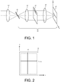
- the figure 1 represents the synoptic of an observation instrument according to the invention.
- the components are represented in bold lines, the propagation of light rays in fine lines.
- the instrument has two main parts.
- the front part is a telescope symbolized by the optical 10.
- the rear part is a spectrometer 20.
- This instrument is intended to be on board a satellite. More generally, it can operate on board any mobile carrier.
- the telescope 10 has several mirrors.
- This type of optical architecture is well known to those skilled in the art.
- the image coming from the earth is focused by the telescope in an intermediate focal plane containing a slot 21, which, projected on the earth's surface, makes it possible to delimit the zone whose spectrum is to be measured.
- This slot delimiting the area of the Earth observed, is re-imagined by the spectrometer 20.
- the latter consists of a collimator 22 making it possible to send the image of the slit after collimation to a dispersion grating 23 which disperses the different wavelengths of the spectral band considered in different directions which are then focused by an imager 24 on the photodetector 25 of the spectrometer.
- the realization of the collimator 22, the dispersion grating 23, the imager 24 and the detector 25 are well known to those skilled in the art.
- the optics chosen are catadioptric type.
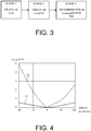
- the photodetector 25 is arranged in a plane (x, y). It comprises a matrix composed of columns Ci of lines Lj of photoreceptors as seen on FIG. figure 2 .
- the dispersion of the network is along the y axis corresponding to lines Lj of the detector.
- Each wavelength ⁇ j is therefore associated with a particular position on the lines Lj of the detector 25.
- the image of the slot is made along the y-axis of the detector. Therefore, each line Lj corresponds to an image of the slot at a known length ⁇ j, each column Ci corresponds to the spectral decomposition of a point of the image on a spectral band which depends on the dispersion properties of the network and its implementation.
- the performance of a spectrometer is, among others, quantified by its ISRF, which represents the response of the instrument to a given wavelength.
- the performance of the spectrometers is thus guaranteed by a maximum level of variation of this error.
- the optical architecture of the spectrometer comprises a phase mask.
- This phase mask introduces a particular variation in the pupil of the spectrometer of the shape of the wavefront or "WFE", acronym for "Wave Front Error”.
- This is arranged near the pupil of the spectrometer. There are different techniques to make this type of mask. They are known to those skilled in the art.
- wavefront coding The method of introducing a WFE into the pupil is called wavefront coding or "wavefront coding” and was originally published in a publication of Edward R. Dowski and W. Thomas Cathey entitled “Extended depth of field through wave-front coding,” Appl. Opt. 34, 1859-1866 (1995) ).
- This technique has nevertheless been proposed initially for imaging and requires the addition of a digital postprocessing in order to reduce the impact of the WFE of the inserted mask, which greatly degrades the image quality at the output of the instrument.
- the geometry of the phase masks can be more or less complex depending on the desired phase error.
- the phase mask depends at least on a parameter ⁇ which may be, for example, the maximum phase variation over the entire mask.
- the parameter ⁇ can also be a geometrical parameter.
- the phase profile can be cubic or "CPP" for "Constant Profile Path” or trigonometric or annular or polynomial.
- the annular masks are composed of concentric rings, each ring introducing a constant and different phase according to the ring.
- the polynomial masks are referenced in a (x, y) frame, the phase variation of the phase filter is a polynomial in x and y.
- the phase variation of the phase filter is a polynomial in r, where r represents the distance at the center of the filter.
- spectral resolution of a spectrometer is defined by its "FWHM", an acronym for "Full Width at Half Maximum".
- FWHM Full Width at Half Maximum
- the introduction of a phase mask does not require a dedicated digital postprocessing to restore the degraded image quality by its introduction. This is an essential advantage of the process according to the invention.
- the process according to the invention is represented on the figure 3 .
- the method is described with a phase mask dependent on a single parameter a. It is easily generalized to several parameters.
- FWHM M optical resolution of the phase mask spectrometer without a phase mask
- FWHM M optical resolution of the phase mask spectrometer
- ⁇ FWHM maximum deviation
- phase mask does not introduce significant variations that are incompatible with the other specifications of the instrument.
- the minimum of the shape error ⁇ SHAPE is calculated by varying the parameter ⁇ under the constraint that the maximum deviation ⁇ FWHM remains below a threshold given by the system specifications.
- the parameter ⁇ MIN corresponding to the optimum of this optimization problem is retained for the development of the phase mask.
- the parameters calculated at the end of this last step then define the WFE making it possible to make the instrument insensitive to the variation range of the aberrations considered.
- the introduction of this WFE in the spectrometer is carried out by inserting in the optical chain of the latter one or more surfaces specifically designed to allow the introduction into the pupil of the optical system phase mask profile determined at the end of the process optimization. Such an operation can for example be performed by modifying the surface on which is inscribed the network located in a pupil plane.
- the figure 4 represents the percentage shape error as a function of defocusing expressed in microns for a spectrometer optical system.
- the dashed curve C1 represents the shape error in the absence of a phase mask and the curve C2 in solid lines the shape error in the presence of an optimized phase mask according to the method according to the invention.
- the shape error becomes in this case much less sensitive to the lack of focus.
- the gain is, for a maximum defocus of 10 microns, a factor of 10.
- the main advantage of the process according to the invention is that it makes it possible to minimize the modifications of the optical chain of the spectrometer, the main optical components of the spectrometer not being modified.
Landscapes
- Physics & Mathematics (AREA)
- Spectroscopy & Molecular Physics (AREA)
- General Physics & Mathematics (AREA)
- Optics & Photonics (AREA)
- Spectrometry And Color Measurement (AREA)
Abstract
Description
- Le domaine de l'invention est celui de la spectrométrie et, tout particulièrement, celui de la spectrométrie embarquée sur satellite, permettant notamment de réaliser de l'analyse spectrale de la terre depuis l'orbite terrestre.
- La qualité d'un instrument comportant un spectromètre optique est caractérisée en particulier par une fonction dite « ISRF », acronyme de « Instrument Spectral Response Function » qui représente la réponse de l'instrument en fonction de la longueur d'onde. Lorsque cet instrument est embarqué sur un satellite et qu'il est soumis à l'environnement spatial, il est nécessaire de limiter toute évolution de son ISRF de façon à conserver une réponse stable de l'instrument.
- La stabilité de l'ISRF est à ce jour assurée en limitant autant que possible l'apparition de perturbateurs ayant un impact sur cette dernière. On citera, notamment, comme principal perturbateur, la défocalisation ou « défocus ». Ce dernier, caractérisé par un décalage d'un ou de plusieurs éléments optiques de l'instrument ou encore du détecteur le long de l'axe optique, a un impact substantiel sur la forme de l'ISRF. Cette défocalisation peut, par exemple, être le fait de déformations mécaniques ou de variations thermiques.
- Aussi, les spectromètres sont aujourd'hui conçus avec des contraintes optiques, mécaniques et thermiques fortes de manière à assurer la stabilité des différents éléments de la chaine optique, permettant ainsi de maintenir dans l'instrument une variation de défauts optiques faible, induisant une déformation de l'ISRF compatible des spécifications techniques.
- Cette stabilité est obtenue au prix de contraintes spécifiques fortes sur le design de l'instrument et qui ne sont pas sans conséquences sur la complexité de ce dernier. La structure mécanique soutenant la chaine optique doit ainsi être suffisamment stable pour garantir la performance requise. Par ailleurs, les variations thermiques de l'ensemble doivent être particulièrement bien maîtrisées pour assurer un niveau de stabilité suffisant au niveau de l'instrument. De telles contraintes impliquent la mise en place de stratégies de régulations thermiques potentiellement couteuses et contraignantes dans la conception et la réalisation de l'instrument.
- Contrairement aux approches techniques de l'art antérieur qui reposent sur la limitation de la quantité de défocus présente dans le spectromètre, la solution technique selon l'invention consiste à rechercher la forme de front d'onde ou « WFE », acronyme de « Wave Front Error » qui, une fois introduite dans le spectromètre, permet de minimiser, par exemple, sa sensibilité au défocus. Autrement dit, cette nouvelle approche repose sur la recherche de la forme de front d'onde minimisant la déformation de l'ISRF de l'instrument considéré pour différentes amplitudes de défocus. Une fois déterminée, cette forme de front d'onde est introduite dans la pupille du spectromètre, par exemple au moyen d'un masque de phase. Ce procédé peut être appliqué, dans le même but, à d'autres aberrations optiques.
- L'augmentation de la tolérance de l'instrument au défocus ou à d'autres aberrations optiques induite par cette modification de l'architecture optique et par l'introduction du masque de phase permet alors d'assouplir les contraintes optiques, mécaniques et thermiques associées à la réalisation de l'instrument. Ce procédé permet donc de simplifier significativement la conception de l'instrument.
- Plus précisément, l'invention a pour objet un procédé de calcul d'une architecture optique d'un instrument d'observation comportant un spectromètre à fente, ledit instrument étant soumis à une perturbation connue modifiant son architecture optique,
ledit spectromètre comportant une fente d'entrée, un système optique, un masque de phase, un réseau de dispersion spectrale et un détecteur matriciel photosensible, le masque de phase étant défini par au moins un paramètre (α), le système optique, le masque de phase et le réseau de dispersion spectrale étant agencés de façon que l'image spectralement dispersée de la fente d'entrée soit située dans le plan du détecteur matriciel photosensible, - La résolution optique du spectromètre sans masque de phase étant notée FWHM, la résolution optique du spectromètre avec masque de phase étant notée FWHMM, un écart maximal (εFWHM) est défini tel que, pour tout paramètre (α), le masque de phase doit vérifier :
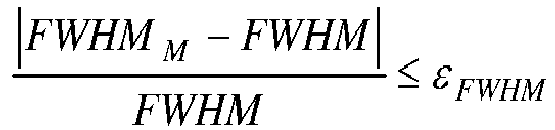
- La résolution minimale en fonction d'une longueur d'onde du spectromètre comportant le masque de phase étant notée ISRF0 et la résolution dégradée à la même longueur d'onde en fonction de la valeur de la perturbation connue étant notée ISFRt, l'erreur de forme est évaluée. Elle vaut pour l'ensemble des valeurs de la perturbation :

- Le procédé de calcul comporte alors une étape d'optimisation dans laquelle le minimum de l'erreur de forme (εFORME) est déterminé en faisant varier le paramètre (α), le paramètre (αMIN) correspondant à l'optimum de ce problème d'optimisation étant retenu pour l'élaboration du masque de phase.
- Avantageusement, la forme de l'ISRF est insensible à la présence d'une défocalisation déterminée de l'image spectralement dispersée de la fente d'entrée dans le plan du détecteur matriciel photosensible.
- Avantageusement, le système optique comporte un premier ensemble optique collimatant l'image de la fente à l'infini et un second ensemble optique focalisant l'image de cette source dans le plan du détecteur matriciel photosensible, le réseau de dispersion spectrale étant disposé entre le premier ensemble et le second ensemble.
- Avantageusement, le masque de phase s'écrit comme une combinaison linéaire d'un vecteur de paramètres et d'une base polynomiale ou trigonométrique.
- Avantageusement, la conception de l'architecture optique de l'instrument d'observation est réalisée suivant un procédé de calcul tel que défini ci-dessus.
- L'invention sera mieux comprise et d'autres avantages apparaîtront à la lecture de la description qui va suivre donnée à titre non limitatif et grâce aux figures annexées parmi lesquelles :
- La
figure 1 représente un instrument d'observation comportant un spectromètre à fente ; - La
figure 2 représente l'image dans le plan focal du spectromètre à fente ; - La
figure 3 représente les différentes étapes du procédé de calcul d'une architecture optique selon l'invention ; - La
figure 4 représente la variation de l'erreur de forme dans le plan focal du spectromètre dans le cas où le spectromètre ne comporte pas de masque de phase et dans le cas où le spectromètre comporte un masque de phase optimisé selon l'invention. - La
figure 1 représente le synoptique d'un instrument d'observation selon l'invention. Sur cette figure, les composants sont représentés en traits gras, la propagation des rayons lumineux en traits fins. L'instrument comporte deux parties principales. La partie avant est un télescope symbolisé par l'optique 10. La partie arrière est un spectromètre 20. Cet instrument est destiné à être embarqué à bord d'un satellite. Plus généralement, il peut fonctionner à bord de tout porteur mobile. - Généralement, le télescope 10 comporte plusieurs miroirs. Ce type d'architecture optique est bien connu de l'homme du métier. L'image en provenance de la terre est focalisée par le télescope dans un plan focal intermédiaire contenant une fente 21, qui, projetée sur la surface terrestre, permet de délimiter la zone dont on souhaite mesurer le spectre. Cette fente, délimitant la zone de la Terre observée, est ré-imagée par le spectromètre 20. Ce dernier est constitué d'un collimateur 22 permettant d'envoyer l'image de la fente après collimation vers un réseau de dispersion 23 qui disperse les différentes longueurs d'ondes de la bande spectrale considérée dans différentes directions qui sont ensuite focalisés par un imageur 24 sur le photo-détecteur 25 du spectromètre. Là encore, la réalisation du collimateur 22, du réseau de dispersion 23, de l'imageur 24 et du détecteur 25 sont bien connus de l'homme du métier. Généralement, les optiques choisies sont de type catadioptrique.
- Le photo-détecteur 25 est disposé dans un plan (x, y). Il comporte une matrice composée de colonnes Ci de lignes Lj de photorécepteurs comme on le voit sur la
figure 2 . La dispersion du réseau se fait selon l'axe y correspondant aux lignes Lj du détecteur. Chaque longueur d'onde λj, est donc associée à une position particulière sur les lignes Lj du détecteur 25. L'image de la fente est réalisée selon l'axe y du détecteur. Par conséquent, chaque ligne Lj correspond à une image de la fente à une longueur λj connue, chaque colonne Ci correspond à la décomposition spectrale d'un point de l'image sur une bande spectrale qui dépend des propriétés de dispersion du réseau et de son implémentation. - Comme il a été dit, la performance d'un spectromètre est, entre autres, quantifiée par son ISRF, qui représente la réponse de l'instrument à une longueur d'onde donnée. La déformation de cette dernière est l'objet de plusieurs spécifications liées à sa stabilité, dont l'une porte sur l'erreur de forme εforme définie comme suit :

- Dans le procédé selon l'invention, l'architecture optique du spectromètre comporte un masque de phase. Ce masque de phase introduit une variation particulière dans la pupille du spectromètre de la forme du front d'onde ou « WFE », acronyme de « Wave Front Error ».
- Celui-ci est disposé au voisinage de la pupille du spectromètre. Il existe différentes techniques pour réaliser ce type de masque. Elles sont connues de l'homme du métier.
- La méthode consistant à introduire une WFE dans la pupille est appelée codage de front d'onde ou en anglais « wavefront coding » et a été initialement publiée dans une publication de Edward R. Dowski and W. Thomas Cathey intitulée "Extended depth of field through wave-front coding," Appl. Opt. 34, 1859-1866 (1995). Cette technique a néanmoins été proposée initialement pour de l'imagerie et nécessite l'ajout d'un post-traitement numérique afin de réduire l'impact de la WFE du masque inséré, qui dégrade fortement la qualité image en sortie d'instrument. A titre d'exemples, ce problème est traité dans les brevets
US 5 748 371 intitulé "Extended depth of field optical systems" -US 6 842 297 intitulé "Wavefront coding optics" -FR 2 923 028 - La géométrie des masques de phase peut être plus ou moins complexe selon l'erreur de phase souhaitée. Dans tous les cas, le masque de phase dépend au moins d'un paramètre α qui peut être, par exemple, la variation maximale de phase sur l'ensemble du masque. Le paramètre α peut également être un paramètre géométrique. A titre d'exemples, le profil de phase peut être de type cubique ou « CPP » pour « Constant profil Path » ou trigonométrique ou annulaire ou polynomial. Les masques annulaires sont composés d'anneaux concentriques, chaque anneau introduisant une phase constante et différente selon l'anneau. Les masques polynomiaux sont référencés dans un repère (x, y), la variation de phase du filtre de phase est un polynôme en x et en y. Lorsque le masque est à symétrie radiale, la variation de phase du filtre de phase est un polynôme en r, r représentant la distance au centre du filtre.
- La résolution spectrale d'un spectromètre est définie par sa « FWHM », acronyme de « Full Width at Half Maximum ». Pour les instruments d'observation comportant un spectromètre à fente, une image de très bonne qualité n'est pas un prérequis dans la mesure où une des limitations de la résolution est liée à la largeur de la fente d'entrée qui ne peut pas être infiniment étroite. Par conséquent, l'introduction d'un masque de phase ne nécessite pas un post-traitement numérique dédié à restaurer la qualité image dégradée par son introduction. C'est un avantage essentiel du procédé selon l'invention.
- Le procédé selon l'invention est représenté sur la
figure 3 . Pour des raisons de clarté, le procédé est décrit avec un masque de phase dépendant d'un seul paramètre a. Il se généralise facilement à plusieurs paramètres. - La résolution optique du spectromètre sans masque de phase étant notée FWHM, la résolution optique du spectromètre avec masque de phase étant noté FWHMM, un écart maximal εFWHM est défini tel que, pour tout paramètre α, le masque de phase doit vérifier :

- Ainsi, on s'assure que le masque de phase n'introduit pas de variations importantes, incompatibles des autres spécifications de l'instrument.
- La résolution minimale en fonction d'une longueur d'onde du spectromètre comportant le masque de phase étant notée ISRF0 et la résolution dégradée à la même longueur d'onde en fonction de la valeur de la perturbation connue étant notée ISFRt, l'erreur de forme est définie par :

- Dans une étape d'optimisation, on calcule le minimum de l'erreur de forme εFORME en faisant varier le paramètre α, sous la contrainte que l'écart maximal εFWHM reste inférieur à un seuil donné par les spécifications du système. Le paramètre αMIN correspondant à l'optimum de ce problème d'optimisation est retenu pour l'élaboration du masque de phase.
- Les paramètres calculés à l'issue de cette dernière étape définissent alors la WFE permettant de rendre l'instrument insensible à la plage de variation des aberrations considérées. L'introduction de cette WFE dans le spectromètre est réalisée en insérant dans la chaine optique de ce dernier une ou plusieurs surfaces spécifiquement conçues pour permettre d'introduire dans la pupille du système optique le profil du masque de phase déterminé à l'issue du processus d'optimisation. Une telle opération peut par exemple être réalisée en modifiant la surface sur laquelle est inscrit le réseau situé dans un plan pupille.
- A titre d'exemple, la
figure 4 représente l'erreur de forme en pourcentage en fonction de la défocalisation exprimée en microns pour un système optique de spectromètre. La courbe C1 en pointillés représente l'erreur de forme en l'absence de masque de phase et la courbe C2 en trait plein l'erreur de forme en présence d'un masque de phase optimisé selon le procédé selon l'invention. Comme on le voit, l'erreur de forme devient dans ce cas beaucoup moins sensible au défaut de focalisation. Le gain est, pour une défocalisation maximale de 10 microns, d'un facteur 10. - L'avantage principal du procédé selon l'invention est qu'il permet de minimiser les modifications de la chaine optique du spectromètre, les principaux composants optiques du spectromètre n'étant pas modifiés.
Claims (5)
- Procédé de calcul d'une architecture optique d'un instrument d'observation comportant un spectromètre (20) à fente (21), ledit instrument étant soumis à une perturbation connue modifiant son architecture optique,
ledit spectromètre comportant une fente d'entrée (21), un système optique (22, 24), un masque de phase, un réseau de dispersion spectrale (23) et un détecteur matriciel photosensible (24), le masque de phase étant défini par au moins un paramètre (a), le système optique, le masque de phase et le réseau de dispersion spectrale étant agencés de façon que l'image spectralement dispersée de la fente d'entrée soit située dans le plan du détecteur matriciel photosensible,
La résolution spectrale du spectromètre sans masque de phase étant notée FWHM, la résolution optique du spectromètre avec masque de phase étant notée FWHMM, un écart maximal (εFWHM) étant défini tel que, pour tout paramètre (α), le masque de phase vérifiant :

- Procédé de calcul d'une architecture optique d'un instrument d'observation comportant un spectromètre à fente selon la revendication 1, caractérisé en ce que la forme de l'ISRF est insensible à une défocalisation déterminée de l'image spectralement dispersée de la fente d'entrée dans le plan du détecteur matriciel photosensible.
- Procédé de calcul d'une architecture optique d'un instrument d'observation comportant un spectromètre à fente selon l'une des revendications précédentes, caractérisé en ce que le système optique comporte un premier ensemble optique (22) collimatant l'image de la fente (21) à l'infini et un second ensemble optique (24) focalisant l'image de cette source dans le plan du détecteur matriciel photosensible, le réseau de dispersion spectrale (23) étant disposé entre le premier ensemble optique et le second ensemble optique.
- Procédé de calcul d'une architecture optique d'un instrument d'observation comportant un spectromètre à fente selon l'une des revendications précédentes, caractérisé en ce que le masque de phase est cubique ou polynomial.
- Instrument d'observation comportant un spectromètre à fente destiné à être embarqué sur satellite, caractérisé en ce que la conception de l'architecture optique de l'instrument est réalisée suivant un procédé de calcul selon l'une des revendications précédentes.
Applications Claiming Priority (1)
| Application Number | Priority Date | Filing Date | Title |
|---|---|---|---|
| FR1800425A FR3080933B1 (fr) | 2018-05-03 | 2018-05-03 | Procede d'insensibilisation a la defocalisation par masque de phase d'un spectrometre pour instruments d'observation embarques |
Publications (2)
| Publication Number | Publication Date |
|---|---|
| EP3564634A1 true EP3564634A1 (fr) | 2019-11-06 |
| EP3564634B1 EP3564634B1 (fr) | 2021-02-17 |
Family
ID=63490508
Family Applications (1)
| Application Number | Title | Priority Date | Filing Date |
|---|---|---|---|
| EP19169729.1A Active EP3564634B1 (fr) | 2018-05-03 | 2019-04-17 | Procede d'insensibilisation a la defocalisation par masque de phase d'un spectrometre pour instruments d'observation embarques |
Country Status (3)
| Country | Link |
|---|---|
| EP (1) | EP3564634B1 (fr) |
| CA (1) | CA3041691A1 (fr) |
| FR (1) | FR3080933B1 (fr) |
Cited By (1)
| Publication number | Priority date | Publication date | Assignee | Title |
|---|---|---|---|---|
| CN113203477A (zh) * | 2020-02-03 | 2021-08-03 | 唯亚威通讯技术有限公司 | 光学传感器设备 |
Citations (3)
| Publication number | Priority date | Publication date | Assignee | Title |
|---|---|---|---|---|
| FR2923028A1 (fr) * | 2007-10-26 | 2009-05-01 | Thales Sa | Dispositif d'imagerie a codage de pupille sub-longueur d'onde |
| US20120307133A1 (en) * | 2011-05-31 | 2012-12-06 | Lu Gao | System And Method For Extending Depth Of Field In A Lens System By Use Of Color-Dependent Wavefront Coding |
| US20170322077A1 (en) * | 2016-05-04 | 2017-11-09 | Spectro Analytical Instruments Gmbh | Optomechanically compensated spectrometer |
-
2018
- 2018-05-03 FR FR1800425A patent/FR3080933B1/fr not_active Expired - Fee Related
-
2019
- 2019-04-17 EP EP19169729.1A patent/EP3564634B1/fr active Active
- 2019-04-30 CA CA3041691A patent/CA3041691A1/fr active Pending
Patent Citations (3)
| Publication number | Priority date | Publication date | Assignee | Title |
|---|---|---|---|---|
| FR2923028A1 (fr) * | 2007-10-26 | 2009-05-01 | Thales Sa | Dispositif d'imagerie a codage de pupille sub-longueur d'onde |
| US20120307133A1 (en) * | 2011-05-31 | 2012-12-06 | Lu Gao | System And Method For Extending Depth Of Field In A Lens System By Use Of Color-Dependent Wavefront Coding |
| US20170322077A1 (en) * | 2016-05-04 | 2017-11-09 | Spectro Analytical Instruments Gmbh | Optomechanically compensated spectrometer |
Non-Patent Citations (1)
| Title |
|---|
| FRÉDÉRIC DIAZ: "Systeme d'imagerie hybride par codage de pupille", 6 May 2011 (2011-05-06), XP055213287, Retrieved from the Internet <URL:http://tel.archives-ouvertes.fr/tel-00624387/en/> * |
Cited By (1)
| Publication number | Priority date | Publication date | Assignee | Title |
|---|---|---|---|---|
| CN113203477A (zh) * | 2020-02-03 | 2021-08-03 | 唯亚威通讯技术有限公司 | 光学传感器设备 |
Also Published As
| Publication number | Publication date |
|---|---|
| CA3041691A1 (fr) | 2019-11-03 |
| FR3080933A1 (fr) | 2019-11-08 |
| EP3564634B1 (fr) | 2021-02-17 |
| FR3080933B1 (fr) | 2021-04-23 |
Similar Documents
| Publication | Publication Date | Title |
|---|---|---|
| EP4012453B1 (fr) | Système imageur lidar à détection hétérodyne de type fmcw comportant un dispositif de correction de phase du signal de référence | |
| EP3100095B1 (fr) | Dispositif de traitement d'un rayonnement lumineux/optique, procede et systeme de conception d'un tel dispositif | |
| EP2368098B1 (fr) | Spectrometre imageur de type dyson de qualite image amelioree et a faible distorsion | |
| EP2734884B1 (fr) | Dispositif optique d'éclairage conoscopique a cone creux pour microscope optique et procédé de microscopie optique en conoscopie | |
| EP3404463B1 (fr) | Télescope anastigmate bifocal à cinq miroirs | |
| EP2755072B1 (fr) | Dispositif de contrôle optique d'un système d'imagerie | |
| EP3336595B1 (fr) | Telescope compact presentant une pluralite de focales compense par un miroir deformable | |
| FR3060135A1 (fr) | Telescope compact presentant une pluralite de focales compense par des composants optiques aspheriques | |
| EP3564634B1 (fr) | Procede d'insensibilisation a la defocalisation par masque de phase d'un spectrometre pour instruments d'observation embarques | |
| FR3012603A1 (fr) | Spectrometre a grand champ telecentrique, notamment a matrice de mems | |
| FR2942036A1 (fr) | Dispositif autocorrelateur a biprisme pour la mesure temporelle d'impulsions de lumiere ultrabreves. | |
| EP3644032A1 (fr) | Spectromètre imageur et dispositif autocorrélateur optique monocoup comprenant un tel spectromètre imageur | |
| EP2520916A1 (fr) | Télescope multispectral à balayage comportant des moyens d'analyse de front d'onde | |
| WO2020016259A1 (fr) | Méthode et dispositif de caractérisation de filtres optiques | |
| EP2767860A1 (fr) | Dispositif de dépolarisation amelioré | |
| EP2708862B1 (fr) | Instrument d'optique à analyseur de front d'onde | |
| EP2309236B1 (fr) | Téléscope concentrateur de champ destiné à des missions de sondage atmosphérique | |
| EP4544287B1 (fr) | Système de détermination de l'atténuation d'une onde lumineuse traversant un volume d'échantillonnage | |
| FR3059156B1 (fr) | Module de detection optique | |
| EP1079215A1 (fr) | Instrument de spectrométrie infrarouge à haute résolution | |
| WO2026068506A1 (fr) | Capteur à interférogrammes partiels multispectraux pour imageur à interférogrammes partiels multispectraux | |
| Platt et al. | The Design of DOAS Instruments | |
| FR3163448A1 (fr) | Dispositif de mesure d’une image spatio-spectrale à haute résolution utilisant plusieurs détecteurs et une fente inclinée | |
| WO2025141268A1 (fr) | Procédé de génération holographique d'un réseau de points de focalisation | |
| EP3798710A1 (fr) | Telescope de type cassegrain a plan de focal segmente |
Legal Events
| Date | Code | Title | Description |
|---|---|---|---|
| PUAI | Public reference made under article 153(3) epc to a published international application that has entered the european phase |
Free format text: ORIGINAL CODE: 0009012 |
|
| STAA | Information on the status of an ep patent application or granted ep patent |
Free format text: STATUS: THE APPLICATION HAS BEEN PUBLISHED |
|
| AK | Designated contracting states |
Kind code of ref document: A1 Designated state(s): AL AT BE BG CH CY CZ DE DK EE ES FI FR GB GR HR HU IE IS IT LI LT LU LV MC MK MT NL NO PL PT RO RS SE SI SK SM TR |
|
| AX | Request for extension of the european patent |
Extension state: BA ME |
|
| STAA | Information on the status of an ep patent application or granted ep patent |
Free format text: STATUS: REQUEST FOR EXAMINATION WAS MADE |
|
| 17P | Request for examination filed |
Effective date: 20200421 |
|
| RBV | Designated contracting states (corrected) |
Designated state(s): AL AT BE BG CH CY CZ DE DK EE ES FI FR GB GR HR HU IE IS IT LI LT LU LV MC MK MT NL NO PL PT RO RS SE SI SK SM TR |
|
| GRAP | Despatch of communication of intention to grant a patent |
Free format text: ORIGINAL CODE: EPIDOSNIGR1 |
|
| STAA | Information on the status of an ep patent application or granted ep patent |
Free format text: STATUS: GRANT OF PATENT IS INTENDED |
|
| INTG | Intention to grant announced |
Effective date: 20201022 |
|
| GRAS | Grant fee paid |
Free format text: ORIGINAL CODE: EPIDOSNIGR3 |
|
| GRAA | (expected) grant |
Free format text: ORIGINAL CODE: 0009210 |
|
| STAA | Information on the status of an ep patent application or granted ep patent |
Free format text: STATUS: THE PATENT HAS BEEN GRANTED |
|
| AK | Designated contracting states |
Kind code of ref document: B1 Designated state(s): AL AT BE BG CH CY CZ DE DK EE ES FI FR GB GR HR HU IE IS IT LI LT LU LV MC MK MT NL NO PL PT RO RS SE SI SK SM TR |
|
| REG | Reference to a national code |
Ref country code: GB Ref legal event code: FG4D Free format text: NOT ENGLISH |
|
| REG | Reference to a national code |
Ref country code: CH Ref legal event code: EP |
|
| REG | Reference to a national code |
Ref country code: DE Ref legal event code: R096 Ref document number: 602019002498 Country of ref document: DE |
|
| REG | Reference to a national code |
Ref country code: AT Ref legal event code: REF Ref document number: 1362048 Country of ref document: AT Kind code of ref document: T Effective date: 20210315 |
|
| REG | Reference to a national code |
Ref country code: IE Ref legal event code: FG4D Free format text: LANGUAGE OF EP DOCUMENT: FRENCH |
|
| REG | Reference to a national code |
Ref country code: LT Ref legal event code: MG9D |
|
| REG | Reference to a national code |
Ref country code: NL Ref legal event code: MP Effective date: 20210217 |
|
| PG25 | Lapsed in a contracting state [announced via postgrant information from national office to epo] |
Ref country code: NO Free format text: LAPSE BECAUSE OF FAILURE TO SUBMIT A TRANSLATION OF THE DESCRIPTION OR TO PAY THE FEE WITHIN THE PRESCRIBED TIME-LIMIT Effective date: 20210517 Ref country code: PT Free format text: LAPSE BECAUSE OF FAILURE TO SUBMIT A TRANSLATION OF THE DESCRIPTION OR TO PAY THE FEE WITHIN THE PRESCRIBED TIME-LIMIT Effective date: 20210617 Ref country code: LT Free format text: LAPSE BECAUSE OF FAILURE TO SUBMIT A TRANSLATION OF THE DESCRIPTION OR TO PAY THE FEE WITHIN THE PRESCRIBED TIME-LIMIT Effective date: 20210217 Ref country code: BG Free format text: LAPSE BECAUSE OF FAILURE TO SUBMIT A TRANSLATION OF THE DESCRIPTION OR TO PAY THE FEE WITHIN THE PRESCRIBED TIME-LIMIT Effective date: 20210517 Ref country code: HR Free format text: LAPSE BECAUSE OF FAILURE TO SUBMIT A TRANSLATION OF THE DESCRIPTION OR TO PAY THE FEE WITHIN THE PRESCRIBED TIME-LIMIT Effective date: 20210217 Ref country code: FI Free format text: LAPSE BECAUSE OF FAILURE TO SUBMIT A TRANSLATION OF THE DESCRIPTION OR TO PAY THE FEE WITHIN THE PRESCRIBED TIME-LIMIT Effective date: 20210217 Ref country code: GR Free format text: LAPSE BECAUSE OF FAILURE TO SUBMIT A TRANSLATION OF THE DESCRIPTION OR TO PAY THE FEE WITHIN THE PRESCRIBED TIME-LIMIT Effective date: 20210518 |
|
| REG | Reference to a national code |
Ref country code: AT Ref legal event code: MK05 Ref document number: 1362048 Country of ref document: AT Kind code of ref document: T Effective date: 20210217 |
|
| PG25 | Lapsed in a contracting state [announced via postgrant information from national office to epo] |
Ref country code: NL Free format text: LAPSE BECAUSE OF FAILURE TO SUBMIT A TRANSLATION OF THE DESCRIPTION OR TO PAY THE FEE WITHIN THE PRESCRIBED TIME-LIMIT Effective date: 20210217 Ref country code: RS Free format text: LAPSE BECAUSE OF FAILURE TO SUBMIT A TRANSLATION OF THE DESCRIPTION OR TO PAY THE FEE WITHIN THE PRESCRIBED TIME-LIMIT Effective date: 20210217 Ref country code: LV Free format text: LAPSE BECAUSE OF FAILURE TO SUBMIT A TRANSLATION OF THE DESCRIPTION OR TO PAY THE FEE WITHIN THE PRESCRIBED TIME-LIMIT Effective date: 20210217 Ref country code: PL Free format text: LAPSE BECAUSE OF FAILURE TO SUBMIT A TRANSLATION OF THE DESCRIPTION OR TO PAY THE FEE WITHIN THE PRESCRIBED TIME-LIMIT Effective date: 20210217 Ref country code: SE Free format text: LAPSE BECAUSE OF FAILURE TO SUBMIT A TRANSLATION OF THE DESCRIPTION OR TO PAY THE FEE WITHIN THE PRESCRIBED TIME-LIMIT Effective date: 20210217 |
|
| PG25 | Lapsed in a contracting state [announced via postgrant information from national office to epo] |
Ref country code: IS Free format text: LAPSE BECAUSE OF FAILURE TO SUBMIT A TRANSLATION OF THE DESCRIPTION OR TO PAY THE FEE WITHIN THE PRESCRIBED TIME-LIMIT Effective date: 20210617 |
|
| PG25 | Lapsed in a contracting state [announced via postgrant information from national office to epo] |
Ref country code: AT Free format text: LAPSE BECAUSE OF FAILURE TO SUBMIT A TRANSLATION OF THE DESCRIPTION OR TO PAY THE FEE WITHIN THE PRESCRIBED TIME-LIMIT Effective date: 20210217 Ref country code: SM Free format text: LAPSE BECAUSE OF FAILURE TO SUBMIT A TRANSLATION OF THE DESCRIPTION OR TO PAY THE FEE WITHIN THE PRESCRIBED TIME-LIMIT Effective date: 20210217 Ref country code: CZ Free format text: LAPSE BECAUSE OF FAILURE TO SUBMIT A TRANSLATION OF THE DESCRIPTION OR TO PAY THE FEE WITHIN THE PRESCRIBED TIME-LIMIT Effective date: 20210217 Ref country code: EE Free format text: LAPSE BECAUSE OF FAILURE TO SUBMIT A TRANSLATION OF THE DESCRIPTION OR TO PAY THE FEE WITHIN THE PRESCRIBED TIME-LIMIT Effective date: 20210217 |
|
| REG | Reference to a national code |
Ref country code: DE Ref legal event code: R097 Ref document number: 602019002498 Country of ref document: DE |
|
| PG25 | Lapsed in a contracting state [announced via postgrant information from national office to epo] |
Ref country code: RO Free format text: LAPSE BECAUSE OF FAILURE TO SUBMIT A TRANSLATION OF THE DESCRIPTION OR TO PAY THE FEE WITHIN THE PRESCRIBED TIME-LIMIT Effective date: 20210217 Ref country code: SK Free format text: LAPSE BECAUSE OF FAILURE TO SUBMIT A TRANSLATION OF THE DESCRIPTION OR TO PAY THE FEE WITHIN THE PRESCRIBED TIME-LIMIT Effective date: 20210217 Ref country code: DK Free format text: LAPSE BECAUSE OF FAILURE TO SUBMIT A TRANSLATION OF THE DESCRIPTION OR TO PAY THE FEE WITHIN THE PRESCRIBED TIME-LIMIT Effective date: 20210217 Ref country code: MC Free format text: LAPSE BECAUSE OF FAILURE TO SUBMIT A TRANSLATION OF THE DESCRIPTION OR TO PAY THE FEE WITHIN THE PRESCRIBED TIME-LIMIT Effective date: 20210217 |
|
| PLBE | No opposition filed within time limit |
Free format text: ORIGINAL CODE: 0009261 |
|
| STAA | Information on the status of an ep patent application or granted ep patent |
Free format text: STATUS: NO OPPOSITION FILED WITHIN TIME LIMIT |
|
| PG25 | Lapsed in a contracting state [announced via postgrant information from national office to epo] |
Ref country code: LU Free format text: LAPSE BECAUSE OF NON-PAYMENT OF DUE FEES Effective date: 20210417 |
|
| 26N | No opposition filed |
Effective date: 20211118 |
|
| PG25 | Lapsed in a contracting state [announced via postgrant information from national office to epo] |
Ref country code: AL Free format text: LAPSE BECAUSE OF FAILURE TO SUBMIT A TRANSLATION OF THE DESCRIPTION OR TO PAY THE FEE WITHIN THE PRESCRIBED TIME-LIMIT Effective date: 20210217 Ref country code: ES Free format text: LAPSE BECAUSE OF FAILURE TO SUBMIT A TRANSLATION OF THE DESCRIPTION OR TO PAY THE FEE WITHIN THE PRESCRIBED TIME-LIMIT Effective date: 20210217 |
|
| PG25 | Lapsed in a contracting state [announced via postgrant information from national office to epo] |
Ref country code: SI Free format text: LAPSE BECAUSE OF FAILURE TO SUBMIT A TRANSLATION OF THE DESCRIPTION OR TO PAY THE FEE WITHIN THE PRESCRIBED TIME-LIMIT Effective date: 20210217 |
|
| PG25 | Lapsed in a contracting state [announced via postgrant information from national office to epo] |
Ref country code: IE Free format text: LAPSE BECAUSE OF NON-PAYMENT OF DUE FEES Effective date: 20210417 |
|
| PG25 | Lapsed in a contracting state [announced via postgrant information from national office to epo] |
Ref country code: IS Free format text: LAPSE BECAUSE OF FAILURE TO SUBMIT A TRANSLATION OF THE DESCRIPTION OR TO PAY THE FEE WITHIN THE PRESCRIBED TIME-LIMIT Effective date: 20210617 |
|
| REG | Reference to a national code |
Ref country code: CH Ref legal event code: PL |
|
| PG25 | Lapsed in a contracting state [announced via postgrant information from national office to epo] |
Ref country code: LI Free format text: LAPSE BECAUSE OF NON-PAYMENT OF DUE FEES Effective date: 20220430 Ref country code: CH Free format text: LAPSE BECAUSE OF NON-PAYMENT OF DUE FEES Effective date: 20220430 |
|
| PG25 | Lapsed in a contracting state [announced via postgrant information from national office to epo] |
Ref country code: CY Free format text: LAPSE BECAUSE OF FAILURE TO SUBMIT A TRANSLATION OF THE DESCRIPTION OR TO PAY THE FEE WITHIN THE PRESCRIBED TIME-LIMIT Effective date: 20210217 |
|
| PG25 | Lapsed in a contracting state [announced via postgrant information from national office to epo] |
Ref country code: HU Free format text: LAPSE BECAUSE OF FAILURE TO SUBMIT A TRANSLATION OF THE DESCRIPTION OR TO PAY THE FEE WITHIN THE PRESCRIBED TIME-LIMIT; INVALID AB INITIO Effective date: 20190417 |
|
| GBPC | Gb: european patent ceased through non-payment of renewal fee |
Effective date: 20230417 |
|
| PG25 | Lapsed in a contracting state [announced via postgrant information from national office to epo] |
Ref country code: GB Free format text: LAPSE BECAUSE OF NON-PAYMENT OF DUE FEES Effective date: 20230417 |
|
| PG25 | Lapsed in a contracting state [announced via postgrant information from national office to epo] |
Ref country code: GB Free format text: LAPSE BECAUSE OF NON-PAYMENT OF DUE FEES Effective date: 20230417 |
|
| PG25 | Lapsed in a contracting state [announced via postgrant information from national office to epo] |
Ref country code: MK Free format text: LAPSE BECAUSE OF FAILURE TO SUBMIT A TRANSLATION OF THE DESCRIPTION OR TO PAY THE FEE WITHIN THE PRESCRIBED TIME-LIMIT Effective date: 20210217 |
|
| PG25 | Lapsed in a contracting state [announced via postgrant information from national office to epo] |
Ref country code: TR Free format text: LAPSE BECAUSE OF FAILURE TO SUBMIT A TRANSLATION OF THE DESCRIPTION OR TO PAY THE FEE WITHIN THE PRESCRIBED TIME-LIMIT Effective date: 20210217 |
|
| PG25 | Lapsed in a contracting state [announced via postgrant information from national office to epo] |
Ref country code: MT Free format text: LAPSE BECAUSE OF FAILURE TO SUBMIT A TRANSLATION OF THE DESCRIPTION OR TO PAY THE FEE WITHIN THE PRESCRIBED TIME-LIMIT Effective date: 20210217 |
|
| PGFP | Annual fee paid to national office [announced via postgrant information from national office to epo] |
Ref country code: DE Payment date: 20250319 Year of fee payment: 7 |
|
| PGFP | Annual fee paid to national office [announced via postgrant information from national office to epo] |
Ref country code: IT Payment date: 20250326 Year of fee payment: 7 |
|
| PGFP | Annual fee paid to national office [announced via postgrant information from national office to epo] |
Ref country code: BE Payment date: 20260317 Year of fee payment: 8 |
|
| PGFP | Annual fee paid to national office [announced via postgrant information from national office to epo] |
Ref country code: FR Payment date: 20260323 Year of fee payment: 8 |