EP3564521A1 - Internal combustion engine start assistance mechanism - Google Patents
Internal combustion engine start assistance mechanism Download PDFInfo
- Publication number
- EP3564521A1 EP3564521A1 EP18747509.0A EP18747509A EP3564521A1 EP 3564521 A1 EP3564521 A1 EP 3564521A1 EP 18747509 A EP18747509 A EP 18747509A EP 3564521 A1 EP3564521 A1 EP 3564521A1
- Authority
- EP
- European Patent Office
- Prior art keywords
- internal combustion
- combustion engine
- side member
- rotation direction
- starting apparatus
- Prior art date
- Legal status (The legal status is an assumption and is not a legal conclusion. Google has not performed a legal analysis and makes no representation as to the accuracy of the status listed.)
- Withdrawn
Links
Images



Classifications
-
- F—MECHANICAL ENGINEERING; LIGHTING; HEATING; WEAPONS; BLASTING
- F02—COMBUSTION ENGINES; HOT-GAS OR COMBUSTION-PRODUCT ENGINE PLANTS
- F02N—STARTING OF COMBUSTION ENGINES; STARTING AIDS FOR SUCH ENGINES, NOT OTHERWISE PROVIDED FOR
- F02N15/00—Other power-operated starting apparatus; Component parts, details, or accessories, not provided for in, or of interest apart from groups F02N5/00 - F02N13/00
- F02N15/02—Gearing between starting-engines and started engines; Engagement or disengagement thereof
- F02N15/022—Gearing between starting-engines and started engines; Engagement or disengagement thereof the starter comprising an intermediate clutch
-
- F—MECHANICAL ENGINEERING; LIGHTING; HEATING; WEAPONS; BLASTING
- F02—COMBUSTION ENGINES; HOT-GAS OR COMBUSTION-PRODUCT ENGINE PLANTS
- F02N—STARTING OF COMBUSTION ENGINES; STARTING AIDS FOR SUCH ENGINES, NOT OTHERWISE PROVIDED FOR
- F02N5/00—Starting apparatus having mechanical power storage
- F02N5/02—Starting apparatus having mechanical power storage of spring type
-
- B—PERFORMING OPERATIONS; TRANSPORTING
- B60—VEHICLES IN GENERAL
- B60K—ARRANGEMENT OR MOUNTING OF PROPULSION UNITS OR OF TRANSMISSIONS IN VEHICLES; ARRANGEMENT OR MOUNTING OF PLURAL DIVERSE PRIME-MOVERS IN VEHICLES; AUXILIARY DRIVES FOR VEHICLES; INSTRUMENTATION OR DASHBOARDS FOR VEHICLES; ARRANGEMENTS IN CONNECTION WITH COOLING, AIR INTAKE, GAS EXHAUST OR FUEL SUPPLY OF PROPULSION UNITS IN VEHICLES
- B60K6/00—Arrangement or mounting of plural diverse prime-movers for mutual or common propulsion, e.g. hybrid propulsion systems comprising electric motors and internal combustion engines
- B60K6/20—Arrangement or mounting of plural diverse prime-movers for mutual or common propulsion, e.g. hybrid propulsion systems comprising electric motors and internal combustion engines the prime-movers consisting of electric motors and internal combustion engines, e.g. HEVs
- B60K6/22—Arrangement or mounting of plural diverse prime-movers for mutual or common propulsion, e.g. hybrid propulsion systems comprising electric motors and internal combustion engines the prime-movers consisting of electric motors and internal combustion engines, e.g. HEVs characterised by apparatus, components or means specially adapted for HEVs
- B60K6/36—Arrangement or mounting of plural diverse prime-movers for mutual or common propulsion, e.g. hybrid propulsion systems comprising electric motors and internal combustion engines the prime-movers consisting of electric motors and internal combustion engines, e.g. HEVs characterised by apparatus, components or means specially adapted for HEVs characterised by the transmission gearings
-
- B—PERFORMING OPERATIONS; TRANSPORTING
- B60—VEHICLES IN GENERAL
- B60K—ARRANGEMENT OR MOUNTING OF PROPULSION UNITS OR OF TRANSMISSIONS IN VEHICLES; ARRANGEMENT OR MOUNTING OF PLURAL DIVERSE PRIME-MOVERS IN VEHICLES; AUXILIARY DRIVES FOR VEHICLES; INSTRUMENTATION OR DASHBOARDS FOR VEHICLES; ARRANGEMENTS IN CONNECTION WITH COOLING, AIR INTAKE, GAS EXHAUST OR FUEL SUPPLY OF PROPULSION UNITS IN VEHICLES
- B60K6/00—Arrangement or mounting of plural diverse prime-movers for mutual or common propulsion, e.g. hybrid propulsion systems comprising electric motors and internal combustion engines
- B60K6/20—Arrangement or mounting of plural diverse prime-movers for mutual or common propulsion, e.g. hybrid propulsion systems comprising electric motors and internal combustion engines the prime-movers consisting of electric motors and internal combustion engines, e.g. HEVs
- B60K6/22—Arrangement or mounting of plural diverse prime-movers for mutual or common propulsion, e.g. hybrid propulsion systems comprising electric motors and internal combustion engines the prime-movers consisting of electric motors and internal combustion engines, e.g. HEVs characterised by apparatus, components or means specially adapted for HEVs
- B60K6/40—Arrangement or mounting of plural diverse prime-movers for mutual or common propulsion, e.g. hybrid propulsion systems comprising electric motors and internal combustion engines the prime-movers consisting of electric motors and internal combustion engines, e.g. HEVs characterised by apparatus, components or means specially adapted for HEVs characterised by the assembly or relative disposition of components
-
- B—PERFORMING OPERATIONS; TRANSPORTING
- B60—VEHICLES IN GENERAL
- B60K—ARRANGEMENT OR MOUNTING OF PROPULSION UNITS OR OF TRANSMISSIONS IN VEHICLES; ARRANGEMENT OR MOUNTING OF PLURAL DIVERSE PRIME-MOVERS IN VEHICLES; AUXILIARY DRIVES FOR VEHICLES; INSTRUMENTATION OR DASHBOARDS FOR VEHICLES; ARRANGEMENTS IN CONNECTION WITH COOLING, AIR INTAKE, GAS EXHAUST OR FUEL SUPPLY OF PROPULSION UNITS IN VEHICLES
- B60K6/00—Arrangement or mounting of plural diverse prime-movers for mutual or common propulsion, e.g. hybrid propulsion systems comprising electric motors and internal combustion engines
- B60K6/20—Arrangement or mounting of plural diverse prime-movers for mutual or common propulsion, e.g. hybrid propulsion systems comprising electric motors and internal combustion engines the prime-movers consisting of electric motors and internal combustion engines, e.g. HEVs
- B60K6/42—Arrangement or mounting of plural diverse prime-movers for mutual or common propulsion, e.g. hybrid propulsion systems comprising electric motors and internal combustion engines the prime-movers consisting of electric motors and internal combustion engines, e.g. HEVs characterised by the architecture of the hybrid electric vehicle
- B60K6/48—Parallel type
- B60K6/485—Motor-assist type
-
- B—PERFORMING OPERATIONS; TRANSPORTING
- B60—VEHICLES IN GENERAL
- B60K—ARRANGEMENT OR MOUNTING OF PROPULSION UNITS OR OF TRANSMISSIONS IN VEHICLES; ARRANGEMENT OR MOUNTING OF PLURAL DIVERSE PRIME-MOVERS IN VEHICLES; AUXILIARY DRIVES FOR VEHICLES; INSTRUMENTATION OR DASHBOARDS FOR VEHICLES; ARRANGEMENTS IN CONNECTION WITH COOLING, AIR INTAKE, GAS EXHAUST OR FUEL SUPPLY OF PROPULSION UNITS IN VEHICLES
- B60K6/00—Arrangement or mounting of plural diverse prime-movers for mutual or common propulsion, e.g. hybrid propulsion systems comprising electric motors and internal combustion engines
- B60K6/20—Arrangement or mounting of plural diverse prime-movers for mutual or common propulsion, e.g. hybrid propulsion systems comprising electric motors and internal combustion engines the prime-movers consisting of electric motors and internal combustion engines, e.g. HEVs
- B60K6/50—Architecture of the driveline characterised by arrangement or kind of transmission units
- B60K6/54—Transmission for changing ratio
-
- F—MECHANICAL ENGINEERING; LIGHTING; HEATING; WEAPONS; BLASTING
- F02—COMBUSTION ENGINES; HOT-GAS OR COMBUSTION-PRODUCT ENGINE PLANTS
- F02N—STARTING OF COMBUSTION ENGINES; STARTING AIDS FOR SUCH ENGINES, NOT OTHERWISE PROVIDED FOR
- F02N11/00—Starting of engines by means of electric motors
-
- F—MECHANICAL ENGINEERING; LIGHTING; HEATING; WEAPONS; BLASTING
- F02—COMBUSTION ENGINES; HOT-GAS OR COMBUSTION-PRODUCT ENGINE PLANTS
- F02N—STARTING OF COMBUSTION ENGINES; STARTING AIDS FOR SUCH ENGINES, NOT OTHERWISE PROVIDED FOR
- F02N15/00—Other power-operated starting apparatus; Component parts, details, or accessories, not provided for in, or of interest apart from groups F02N5/00 - F02N13/00
- F02N15/02—Gearing between starting-engines and started engines; Engagement or disengagement thereof
-
- F—MECHANICAL ENGINEERING; LIGHTING; HEATING; WEAPONS; BLASTING
- F02—COMBUSTION ENGINES; HOT-GAS OR COMBUSTION-PRODUCT ENGINE PLANTS
- F02N—STARTING OF COMBUSTION ENGINES; STARTING AIDS FOR SUCH ENGINES, NOT OTHERWISE PROVIDED FOR
- F02N19/00—Starting aids for combustion engines, not otherwise provided for
- F02N19/005—Aiding engine start by starting from a predetermined position, e.g. pre-positioning or reverse rotation
-
- F—MECHANICAL ENGINEERING; LIGHTING; HEATING; WEAPONS; BLASTING
- F16—ENGINEERING ELEMENTS AND UNITS; GENERAL MEASURES FOR PRODUCING AND MAINTAINING EFFECTIVE FUNCTIONING OF MACHINES OR INSTALLATIONS; THERMAL INSULATION IN GENERAL
- F16F—SPRINGS; SHOCK-ABSORBERS; MEANS FOR DAMPING VIBRATION
- F16F15/00—Suppression of vibrations in systems; Means or arrangements for avoiding or reducing out-of-balance forces, e.g. due to motion
- F16F15/10—Suppression of vibrations in rotating systems by making use of members moving with the system
- F16F15/12—Suppression of vibrations in rotating systems by making use of members moving with the system using elastic members or friction-damping members, e.g. between a rotating shaft and a gyratory mass mounted thereon
- F16F15/121—Suppression of vibrations in rotating systems by making use of members moving with the system using elastic members or friction-damping members, e.g. between a rotating shaft and a gyratory mass mounted thereon using springs as elastic members, e.g. metallic springs
- F16F15/124—Elastomeric springs
- F16F15/1245—Elastic elements arranged between substantially-radial walls of two parts rotatable with respect to each other, e.g. between engaging teeth
-
- F—MECHANICAL ENGINEERING; LIGHTING; HEATING; WEAPONS; BLASTING
- F02—COMBUSTION ENGINES; HOT-GAS OR COMBUSTION-PRODUCT ENGINE PLANTS
- F02N—STARTING OF COMBUSTION ENGINES; STARTING AIDS FOR SUCH ENGINES, NOT OTHERWISE PROVIDED FOR
- F02N11/00—Starting of engines by means of electric motors
- F02N11/04—Starting of engines by means of electric motors the motors being associated with current generators
-
- F—MECHANICAL ENGINEERING; LIGHTING; HEATING; WEAPONS; BLASTING
- F02—COMBUSTION ENGINES; HOT-GAS OR COMBUSTION-PRODUCT ENGINE PLANTS
- F02N—STARTING OF COMBUSTION ENGINES; STARTING AIDS FOR SUCH ENGINES, NOT OTHERWISE PROVIDED FOR
- F02N19/00—Starting aids for combustion engines, not otherwise provided for
- F02N19/005—Aiding engine start by starting from a predetermined position, e.g. pre-positioning or reverse rotation
- F02N2019/007—Aiding engine start by starting from a predetermined position, e.g. pre-positioning or reverse rotation using inertial reverse rotation
Definitions
- the present invention relates to an internal combustion engine start assist mechanism applicable to, for example, a power transmitting apparatus with rotary electrical machine that integrates a power generating function and an engine start function of a vehicle's alternator and a vehicle's starter motor.
- an alternator 105 connected to a pulley 103 provided at a crankshaft end 102 of an internal combustion engine 101 via a V-belt 104 is known.
- an apparatus in which the alternator 105 is additionally provided with a driving function to be capable of starting an internal combustion engine in a warm state (after a warm-up) (refer to integrated starter generators (ISGs) disclosed in PTLs 1 to 3) and further performing a driving force assist while a vehicle is travelling, or the like is known.
- a driving function to be capable of starting an internal combustion engine in a warm state (after a warm-up) (refer to integrated starter generators (ISGs) disclosed in PTLs 1 to 3) and further performing a driving force assist while a vehicle is travelling, or the like is known.
- the method for starting an internal combustion engine described above may fail to start the engine in a cold state. This is because in the cold state, for example, a decrease in temperature of a lubricating oil in the internal combustion engine causes increases in viscosity of the lubricating oil and in agitating resistance during startup, and a decrease in friction coefficient between the V-belt 104 and the pulley 103 causes slippage to occur between the V-belt 104 and the pulley 103, thereby preventing a rotational driving force of the alternator 105 from being transmitted to the internal combustion engine 101.
- a vehicle equipped with such an apparatus includes, without exception, a starter motor 106 in addition to the alternator 105 for the cold start of an internal combustion engine.
- a starter motor 106 in addition to the alternator 105 for the cold start of an internal combustion engine.
- a ring gear is denoted by 107
- a starting apparatus such as a torque converter is denoted by 108
- a transmission is denoted by 109.
- an object of the present invention having been conceived to solve the problem, is to provide an internal combustion engine start assist mechanism in which an internal combustion engine and a starting apparatus are coupled with each other without a V-belt and a pulley to enable a reliable start even in a cold state, specifically, under a condition such as at an extremely low temperature ranging from, for example, -20°C to -30°C.
- an internal combustion engine start assist mechanism comprising:
- the relative gap and the elastic member are arranged between the starting apparatus side member connected to a starting apparatus and the internal combustion engine side member connected to the internal combustion engine along the rotation direction, and after rotation of the starting apparatus side member in a direction opposite to a start rotation direction forms a gap between the starting apparatus side member and the internal combustion engine side member to temporally contract the elastic member, rotation of the starting apparatus side member in the start rotation direction generates torque equal to or greater than static torque of the starting apparatus by using torque generated by the biasing force of the elastic member to enable the internal combustion engine to start.
- an internal combustion engine start assist mechanism 20 is configured to obtain a torque and engine start.
- the torque is equal to or greater than static torque of the rotary electrical machine 16 using a gap 12 provided between the rotary electrical machine 16 and the engine 13, the gap 12 in which rotation directions are relative to each other, and a bias applied by an elastic member 3.
- the engine start means to start the engine under a condition such as at an extremely low temperature ranging from, for example, -20°C to -30°C where required torque increases and the start of the engine accordingly becomes difficult.
- a target to which such the internal combustion engine start assist mechanism 20 is applied includes a power transmitting apparatus with rotary electrical machine.
- An example of the power transmitting apparatus with rotary electrical machine has a configuration in which a power transmitting apparatus 17 such as a clutch or a torque converter is combined with the rotary electrical machine 16 to integrate respective functions of an integrated starter generator (ISG) and a starter motor, thereby bringing about advantages in terms of cost and space.
- ISG integrated starter generator
- Incorporating the internal combustion engine start assist mechanism 20 into the configuration enables a rotational driving force of the rotary electrical machine 16 to be reliably transmitted to the engine 13 even in a cold state, and thus enables a reliable start of the engine 13 in the cold state.
- a power generating function of an alternator and an engine start function of a starter motor are integrated to enable only the rotary electrical machine 16 to perform both the functions, resulting in reducing the cost and space.
- the internal combustion engine start assist mechanism 20 includes elastic members 3, stopper portions 2c of an internal combustion engine side member 2, and contact portions 1c of a starting apparatus side member 1.
- the starting apparatus side member 1 is connected to a starting apparatus, i.e., the rotary electrical machine 16 and transmits torque at startup from the starting apparatus toward the internal combustion engine.
- the internal combustion engine side member 2 is a member that is connected to an output shaft 15 of the internal combustion engine, i.e., the engine 13 and rotates integrally with the output shaft 15 of the engine 13.
- Examples of the internal combustion engine side member 2 may include a member disposed on an engine side or an outer shell of a torque converter as an example of the power transmitting apparatus 17.
- the elastic member 3 is, for example, a coil spring, and at least two elastic members 3 are arranged. It is preferable that at least two elastic members 3 is arranged point-symmetrically about a center in an internal combustion engine rotation direction 10 from the viewpoint of balancing their respective biasing forces. As an example, four elastic members 3 are arranged at intervals of 90 degrees as shown in Fig. 1A .
- the elastic member 3 is attached to between a first support portion 1b having a recessed shape of the starting apparatus side member 1 and a second support portion 2b having a recessed shape of the internal combustion engine side member 2 to have a biasing force for applying a bias in the internal combustion engine rotation direction 10 (for example, in a counterclockwise direction in Figs. 1A , 2 , and the like).
- the first support portion 1b and the second support portion 2b are positioned facing each other along the internal combustion engine rotation direction 10.
- the internal combustion engine side member 2 is provided with the stopper portions 2c.
- the contact portion 1c of the starting apparatus side member 1 is disposed behind the stopper portion 2c of the internal combustion engine side member 2 in the internal combustion engine rotation direction 10 and is capable of forming the gap 12 relative to the stopper portion 2c of the internal combustion engine side member 2 when the starting apparatus side member 1 rotates in a direction opposite to the internal combustion engine rotation direction 10 and coming into contact with the stopper portion 2c of the internal combustion engine side member 2 when the starting apparatus side member 1 rotates in the internal combustion engine rotation direction 10.
- An interval dimension of the gap 12 is determined in advance by design considering the biasing force applied to the internal combustion engine side member 2 and a mechanical strength at the time of contraction of the elastic member 3, and the like.
- the starting apparatus side member 1 has a plurality of first protrusions 1a having an L-shape protruding at certain angular intervals (for example, 90° intervals) from a first outer circumferential frame portion 1d that is an annular member toward a center in a radial direction.
- a tip of each of the first protrusions 1a having an L-shape corresponds to the contact portion 1c.
- a first depression 1b as the first support portion is provided on a rear side of each of the first protrusions 1a having an L-shape in the internal combustion engine rotation direction 10, and supports a front end of the elastic member 3 in the internal combustion engine rotation direction 10.
- the internal combustion engine side member 2 is disposed inside the starting apparatus side member 1 to be rotatable relative to the starting apparatus side member 1, and has a plurality of second protrusions 2a having an L-shape protruding at certain angular intervals (for example, 90° intervals) outward from a second outer circumferential frame portion 2d that is an annular member in the radial direction.
- An outer circumferential surface in the radial direction of a tip of each of the second protrusions 2a having an L-shape is slidable on an inner circumferential surface in the radial direction of the first outer circumferential frame portion 1d to allow the second protrusion 2a to move relative to the first outer circumferential frame portion 1d.
- a second depression 2b as the second support portion is provided on a front side of each of the second protrusions 2a having an L-shape in the internal combustion engine rotation direction 10, and supports a rear end of the elastic member 3 in the internal combustion engine rotation direction 10.
- the stopper portion 2c protruding outward in the radial direction is formed on the second outer circumferential frame portion 2d ahead of each of the second protrusions 2a in the internal combustion engine rotation direction 10.
- the contact portion 1c having an inner surface in the radial direction slidable on the outer circumferential surface of the second outer circumferential frame portion 2d allows the contact portion 1c to guide to move relative to the second outer circumferential frame portion 2d.
- At least two contact portions 1c of the starting apparatus side member 1 and at least two stopper portions 2c of the internal combustion engine side member 2 are arranged, and it is preferable that these portions are arranged point-symmetrically about the center of the internal combustion engine rotation direction 10 from the viewpoint of a balance.
- an angle range for the reverse rotation is determined in advance by design considering the biasing force applied to the internal combustion engine side member 2 and the mechanical strength at the time of contraction of the elastic member 3, and the like. Macroscopically, the internal combustion engine side member 2 does not rotate due to large resistance torque, allowing the gap 12 and a contraction angle of the elastic member 3 to be approximately identical to each other.
- the use of the configuration of the first embodiment makes it possible to additionally apply dynamic torque to the engine 13 and thus increase starting performance of the engine 13.
- Fig. 6 is a schematic operation time chart.
- the internal combustion engine side member 2 and the starting apparatus side member 1 shown in Figs. 3 to 5 are rotatable relative to each other by the gap 12 that can be relatively formed between the stopper portion 2c and the contact portion 1c, that is, within a certain angle range in a circumferential direction, with their respective protrusions, that is, the first protrusion 1a and the second protrusion 2a, prevented from moving in the radial direction between an inner circumferential surface of the starting apparatus side member 1 and an outer circumferential surface of the internal combustion engine side member 2.
- the starting apparatus is temporally rotated by a certain angle range in a direction (reverse rotation direction) opposite to a normal rotation direction 10 of the engine 13 (refer to A in Fig. 6 ) in the order shown in Figs. 3, 4 , and 5 .
- the contact portions 1c of the starting apparatus side member 1 come into contact with the stopper portions 2c of the internal combustion engine side member 2 that is not moving, and the rotation of the starting apparatus side member 1 is rapidly decelerated. At this time, each of the contact portions 1c comes into contact with each of the stopper portions 2c to make the gap 12 therebetween disappear, and the starting apparatus side member 1 and the internal combustion engine side member 2 start to rotate integrally.
- the torque generated by the starting apparatus itself drives the internal combustion engine side member 2 in the normal rotation direction 10 with the contact portions 1c of the starting apparatus side member 1 and the stopper portions 2c of the internal combustion engine side member 2 kept in contact with each other.
- the relative gaps 12 and the coil springs 3 are arranged between the starting apparatus side member 1 connected to the rotary electrical machine 16 and the internal combustion engine side member 2 connected to the engine 13 along the rotation direction.
- the starting apparatus side member rotates in a direction opposite to the internal combustion engine rotation direction 10 by a predetermined angle to temporally form the gaps 12 and contract the elastic members 3 and then rotates in the internal combustion engine rotation direction 10
- the contact portions 1c of the starting apparatus side member 1 are brought into contact with the stopper portions 2c of the internal combustion engine side member 2
- a combination of the rotation of the starting apparatus side member 1 in the internal combustion engine rotation direction 10 with the rotation in the internal combustion engine rotation direction 10 caused by the biasing force of the elastic members 3 causes the starting apparatus side member 1 to rotate integrally with the internal combustion engine side member 2 in the internal combustion engine rotation direction 10.
- the use of the torque generated by the biasing force of the coil springs 3 makes it possible to obtain torque equal to or greater than the static torque of the rotary electrical machine 16 and start the engine.
- a dynamic torque of an internal combustion engine starting apparatus and compared with a case where only the static torque is used, it is possible to reliably transmit, without a V-belt and a pulley, a rotational driving force of the rotary electrical machine 16 to the engine 13 even in a cold state, specifically, at an extremely low temperature ranging from, for example, -20°C to -30°C and thus reliably start the engine 13.
- the elastic member 3 is not limited to the coil spring and may have the following configuration.
- the elastic members 3 may be constructed as a plurality of leaf springs 31 that are stacked and disposed between a first inner circumferential side support portion 1e and a second outer circumferential side support portion 2e along the radial direction.
- the first inner circumferential side support portion 1e and the second outer circumferential side support portion 2e are provided on the inner circumferential side of the first outer circumferential frame portion 1d of the starting apparatus side member 1 and on the outer circumferential side of the second outer circumferential frame portion 2d of the internal combustion engine side member 2, respectively.
- contracting the elastic members 3 described above corresponds to bending the leaf springs 31 by twist.
- This example acts in the same way as in the first embodiment.
- This example brings about an advantage that a twist angle is smaller than a twist angle of the coil spring, but in a case where a small twist angle is allowed in terms of design, an occupied volume as the elastic members 3 can be made smaller.
- the elastic member 3 may be constructed as a cylinder 32 in which a compressive fluid is sealed, and a piston 33 that moves forward and backward in the cylinder 32.
- the cylinder 32 and the piston 33 are supported between the first depression 1b and the second depression 2b.
- a seal is applied to between the cylinder 32 and the piston 33 to prevent the fluid from leaking.
- Figs. 8A and 8B show states in which the compressive fluid is sealed in.
- Fig. 8A shows a case where the compressive fluid is sealed in, and an internal pressure is low in a stretched state.
- Fig. 8B shows a case where the compressive fluid is sealed in, and the internal pressure is increased in a contracted state.
- This example acts in the same way as in the first embodiment. Further, this example allows an elastic modulus to be freely changed in accordance with a filling amount of the compressive fluid, which brings about an advantage that application design is easy.
- the elastic member 3 may be constructed as an accordion spring 34 supported between the first depression 1b and the second depression 2b. This example acts in the same way as in the first embodiment.
- the elastic member 3 may be constructed as a tension spring 35 supported between the first depression 1b and the second depression 2b.
- the stopper portion 2c is disposed at an outer end in the radial direction of each of the plurality of second protrusions 2a having an L-shape
- the contact portion 1c is disposed at an inner end in the radial direction of each of the plurality of first protrusions 1a having an L-shape.
- the tension spring 35 is attached to between the first support portion 1b having a recessed shape of the starting apparatus side member 1 and the second support portion 2b having a recessed shape of the internal combustion engine side member 2 to have a biasing force for applying a bias in the internal combustion engine rotation direction 10 (for example, in a counterclockwise direction in Fig. 10 ).
- the first support portion 1b and the second support portion 2b are positioned, on a front side and a rear side, respectively, facing each other along the internal combustion engine rotation direction 10. This example acts in the same way as in the first embodiment. This example makes it possible to prevent the spring member from becoming friction-wear due to a centrifugal force.
- the elastic member 3 may be constructed as a columnar rubber elastic body.
- the internal combustion engine start assist mechanism is capable of reliably transmitting, without a V-belt and a pulley, a rotational driving force of the starting apparatus to the internal combustion engine even in a cold state, specifically, under a condition such as at an extremely low temperature ranging from, for example, -20°C to -30°C and thus reliably starting the internal combustion engine in the cold state, and is applicable to, for example, a power transmitting apparatus with rotary electrical machine that integrates a power generating function and an engine start function of a vehicle's alternator and a vehicle's starter motor.
Landscapes
- Engineering & Computer Science (AREA)
- Mechanical Engineering (AREA)
- Chemical & Material Sciences (AREA)
- Combustion & Propulsion (AREA)
- General Engineering & Computer Science (AREA)
- Transportation (AREA)
- Physics & Mathematics (AREA)
- Acoustics & Sound (AREA)
- Aviation & Aerospace Engineering (AREA)
- Hybrid Electric Vehicles (AREA)
- Connection Of Motors, Electrical Generators, Mechanical Devices, And The Like (AREA)
- Devices For Conveying Motion By Means Of Endless Flexible Members (AREA)
Abstract
Description
- The present invention relates to an internal combustion engine start assist mechanism applicable to, for example, a power transmitting apparatus with rotary electrical machine that integrates a power generating function and an engine start function of a vehicle's alternator and a vehicle's starter motor.
- Conventionally, as a power generating apparatus for a vehicle, as shown in
Fig. 11 , analternator 105 connected to apulley 103 provided at acrankshaft end 102 of aninternal combustion engine 101 via a V-belt 104 is known. - Further, an apparatus in which the
alternator 105 is additionally provided with a driving function to be capable of starting an internal combustion engine in a warm state (after a warm-up) (refer to integrated starter generators (ISGs) disclosed inPTLs 1 to 3) and further performing a driving force assist while a vehicle is travelling, or the like is known. -
- PTL 1:
JP 4782348 B2 - PTL 2:
JP 4787242 B2 - PTL 3:
JP 2009-508464 A - However, the method for starting an internal combustion engine described above may fail to start the engine in a cold state. This is because in the cold state, for example, a decrease in temperature of a lubricating oil in the internal combustion engine causes increases in viscosity of the lubricating oil and in agitating resistance during startup, and a decrease in friction coefficient between the V-
belt 104 and thepulley 103 causes slippage to occur between the V-belt 104 and thepulley 103, thereby preventing a rotational driving force of thealternator 105 from being transmitted to theinternal combustion engine 101. - To address such a problem, a vehicle equipped with such an apparatus includes, without exception, a
starter motor 106 in addition to thealternator 105 for the cold start of an internal combustion engine. Note that, inFig. 11 , a ring gear is denoted by 107, a starting apparatus such as a torque converter is denoted by 108, and a transmission is denoted by 109. - Accordingly, an object of the present invention, having been conceived to solve the problem, is to provide an internal combustion engine start assist mechanism in which an internal combustion engine and a starting apparatus are coupled with each other without a V-belt and a pulley to enable a reliable start even in a cold state, specifically, under a condition such as at an extremely low temperature ranging from, for example, -20°C to -30°C.
- According to one aspect of the present invention, there is provided an internal combustion engine start assist mechanism comprising:
- an elastic member that is attached to between a first support portion of a starting apparatus side member and a second support portion of an internal combustion engine side member respectively positioned along an internal combustion engine rotation direction and has a biasing force for applying a bias in the internal combustion engine rotation direction;
- a stopper portion disposed on the internal combustion engine side member that rotates integrally with an output shaft of an internal combustion engine; and
- a contact portion of the starting apparatus side member disposed behind the stopper portion of the internal combustion engine side member in the internal combustion engine rotation direction, the contact portion being capable of forming a gap relative to the stopper portion of the internal combustion engine side member when the starting apparatus side member rotates in a direction opposite to the internal combustion engine rotation direction, and the contact portion coming into contact with the stopper portion of the internal combustion engine side member when the starting apparatus side member rotates in the internal combustion engine rotation direction,
- when the starting apparatus side member rotates in the direction opposite to the internal combustion engine rotation direction by a predetermined angle to temporally contract the elastic member and then rotating in the internal combustion engine rotation direction, the contact portion of the starting apparatus side member being brought into contact with the stopper portion of the internal combustion engine side member, and a combination of the rotation of the starting apparatus side member in the internal combustion engine rotation direction with rotation in the internal combustion engine rotation direction caused by the biasing force of the elastic member causing the starting apparatus side member to rotate integrally with the internal combustion engine side member in the internal combustion engine rotation direction.
- According to the aspect of the present invention, the relative gap and the elastic member are arranged between the starting apparatus side member connected to a starting apparatus and the internal combustion engine side member connected to the internal combustion engine along the rotation direction, and after rotation of the starting apparatus side member in a direction opposite to a start rotation direction forms a gap between the starting apparatus side member and the internal combustion engine side member to temporally contract the elastic member, rotation of the starting apparatus side member in the start rotation direction generates torque equal to or greater than static torque of the starting apparatus by using torque generated by the biasing force of the elastic member to enable the internal combustion engine to start. As a result, it is possible to reliably transmit, without a V-belt and a pulley, a rotational driving force of the starting apparatus to the internal combustion engine even in a cold state, specifically, under a condition such as at an extremely low temperature ranging from, for example, -20°C to -30°C, and reliably start the internal combustion engine in the cold state.
-
-
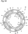
Fig. 1A is a front view showing an entire circumference of an internal combustion engine start assist mechanism according to a first embodiment of the present invention; -
Fig. 1B is an explanatory diagram showing a layout of the internal combustion engine start assist mechanism according to the first embodiment and is a cross-sectional view of the internal combustion engine start assist mechanism that results from rotating the front view ofFig. 1A by 45°; -
Fig. 2 is a partially enlarged front view of the internal combustion engine start assist mechanism; -
Fig. 3 is a partial state explanatory diagram of the internal combustion engine start assist mechanism in an initial position state; -
Fig. 4 is a partial state explanatory diagram of the internal combustion engine start assist mechanism in a state where a twist starts; -
Fig. 5 is a partial state explanatory diagram of the internal combustion engine start assist mechanism in a state where the twist has been further made from the state showing inFig. 4 ; -
Fig. 6 is a schematic operation time chart of the internal combustion engine start assist mechanism; -
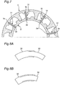
Fig. 7 is an explanatory diagram of a modification of the first embodiment configured with a leaf spring; -
Fig. 8A is an explanatory diagram of a modification of the first embodiment configured with a cylinder and a piston, showing a state where a compressive fluid is sealed in, and an internal pressure is low in a stretched state; -
Fig. 8B is an explanatory diagram of the modification that is the same as that in shown inFig. 8A , showing a state where the compressive fluid is sealed in, and the internal pressure is increased in a contracted state; -
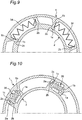
Fig. 9 is an explanatory diagram of a modification of the first embodiment configured with an accordion spring; -
Fig. 10 is an explanatory diagram of a modification of the first embodiment configured with a tension spring; and -
Fig. 11 is an explanatory diagram showing a relation among a conventional internal combustion engine, starter motor, and alternator. - Hereinafter, a first embodiment of the present invention will be described in detail with reference to the drawings. Note that, in description of each embodiment, the same components or portions are denoted by the same reference numeral, and redundant description will be omitted.
- As shown in
Figs. 1A and1B , an internal combustion engine start assistmechanism 20 according to the first embodiment of the present invention is configured to obtain a torque and engine start. In a system for starting an internal combustion engine, i.e., anengine 13, using a rotaryelectrical machine 16 as an example of a starting apparatus, the torque is equal to or greater than static torque of the rotaryelectrical machine 16 using agap 12 provided between the rotaryelectrical machine 16 and theengine 13, thegap 12 in which rotation directions are relative to each other, and a bias applied by anelastic member 3. The engine start means to start the engine under a condition such as at an extremely low temperature ranging from, for example, -20°C to -30°C where required torque increases and the start of the engine accordingly becomes difficult. - A target to which such the internal combustion engine start assist
mechanism 20 is applied includes a power transmitting apparatus with rotary electrical machine. - An example of the power transmitting apparatus with rotary electrical machine has a configuration in which a
power transmitting apparatus 17 such as a clutch or a torque converter is combined with the rotaryelectrical machine 16 to integrate respective functions of an integrated starter generator (ISG) and a starter motor, thereby bringing about advantages in terms of cost and space. Incorporating the internal combustion engine start assistmechanism 20 into the configuration enables a rotational driving force of the rotaryelectrical machine 16 to be reliably transmitted to theengine 13 even in a cold state, and thus enables a reliable start of theengine 13 in the cold state. - Furthermore, in the embodiment of the present invention, when the rotary
electrical machine 16 is disposed in combination with thepower transmitting apparatus 17, a power generating function of an alternator and an engine start function of a starter motor are integrated to enable only the rotaryelectrical machine 16 to perform both the functions, resulting in reducing the cost and space. - Hereinafter, the internal combustion engine start assist
mechanism 20 applicable to such a configuration will be described in detail. - The internal combustion engine start assist
mechanism 20 includeselastic members 3,stopper portions 2c of an internal combustionengine side member 2, andcontact portions 1c of a startingapparatus side member 1. - The starting
apparatus side member 1 is connected to a starting apparatus, i.e., the rotaryelectrical machine 16 and transmits torque at startup from the starting apparatus toward the internal combustion engine. - The internal combustion
engine side member 2 is a member that is connected to anoutput shaft 15 of the internal combustion engine, i.e., theengine 13 and rotates integrally with theoutput shaft 15 of theengine 13. Examples of the internal combustionengine side member 2 may include a member disposed on an engine side or an outer shell of a torque converter as an example of thepower transmitting apparatus 17. - The
elastic member 3 is, for example, a coil spring, and at least twoelastic members 3 are arranged. It is preferable that at least twoelastic members 3 is arranged point-symmetrically about a center in an internal combustion engine rotation direction 10 from the viewpoint of balancing their respective biasing forces. As an example, fourelastic members 3 are arranged at intervals of 90 degrees as shown inFig. 1A . Theelastic member 3 is attached to between afirst support portion 1b having a recessed shape of the startingapparatus side member 1 and asecond support portion 2b having a recessed shape of the internal combustionengine side member 2 to have a biasing force for applying a bias in the internal combustion engine rotation direction 10 (for example, in a counterclockwise direction inFigs. 1A ,2 , and the like). Thefirst support portion 1b and thesecond support portion 2b are positioned facing each other along the internal combustion engine rotation direction 10. - The internal combustion
engine side member 2 is provided with thestopper portions 2c. - The
contact portion 1c of the startingapparatus side member 1 is disposed behind thestopper portion 2c of the internal combustionengine side member 2 in the internal combustion engine rotation direction 10 and is capable of forming thegap 12 relative to thestopper portion 2c of the internal combustionengine side member 2 when the startingapparatus side member 1 rotates in a direction opposite to the internal combustion engine rotation direction 10 and coming into contact with thestopper portion 2c of the internal combustionengine side member 2 when the startingapparatus side member 1 rotates in the internal combustion engine rotation direction 10. An interval dimension of thegap 12 is determined in advance by design considering the biasing force applied to the internal combustionengine side member 2 and a mechanical strength at the time of contraction of theelastic member 3, and the like. - More specifically, the following structure has been adopted.
- The starting
apparatus side member 1 has a plurality offirst protrusions 1a having an L-shape protruding at certain angular intervals (for example, 90° intervals) from a first outercircumferential frame portion 1d that is an annular member toward a center in a radial direction. A tip of each of thefirst protrusions 1a having an L-shape corresponds to thecontact portion 1c. Afirst depression 1b as the first support portion is provided on a rear side of each of thefirst protrusions 1a having an L-shape in the internal combustion engine rotation direction 10, and supports a front end of theelastic member 3 in the internal combustion engine rotation direction 10. - The internal combustion
engine side member 2 is disposed inside the startingapparatus side member 1 to be rotatable relative to the startingapparatus side member 1, and has a plurality ofsecond protrusions 2a having an L-shape protruding at certain angular intervals (for example, 90° intervals) outward from a second outercircumferential frame portion 2d that is an annular member in the radial direction. An outer circumferential surface in the radial direction of a tip of each of thesecond protrusions 2a having an L-shape is slidable on an inner circumferential surface in the radial direction of the first outercircumferential frame portion 1d to allow thesecond protrusion 2a to move relative to the first outercircumferential frame portion 1d. Asecond depression 2b as the second support portion is provided on a front side of each of thesecond protrusions 2a having an L-shape in the internal combustion engine rotation direction 10, and supports a rear end of theelastic member 3 in the internal combustion engine rotation direction 10. - The
stopper portion 2c protruding outward in the radial direction is formed on the second outercircumferential frame portion 2d ahead of each of thesecond protrusions 2a in the internal combustion engine rotation direction 10. When each of thestopper portions 2c allows thecontact portion 1c of the startingapparatus side member 1 to come into contact and engage therewith, and thecontact portion 1c engages with thestopper portion 2c, the startingapparatus side member 1 and the internal combustionengine side member 2 integrally rotate in the internal combustion engine rotation direction 10. On the other hand, rotation in a direction opposite to the internal combustion engine rotation direction 10 against the biasing force of theelastic member 3 allows thecontact portion 1c to separate from thestopper portion 2c to form therelative gap 12. At this time, thecontact portion 1c having an inner surface in the radial direction slidable on the outer circumferential surface of the second outercircumferential frame portion 2d allows thecontact portion 1c to guide to move relative to the second outercircumferential frame portion 2d. - Note that it is preferable that at least two
contact portions 1c of the startingapparatus side member 1 and at least twostopper portions 2c of the internal combustionengine side member 2 are arranged, and it is preferable that these portions are arranged point-symmetrically about the center of the internal combustion engine rotation direction 10 from the viewpoint of a balance. - In such a configuration, when the starting
apparatus side member 1 rotates in a direction opposite to the internal combustion engine rotation direction 10 by a predetermined angle to temporally contract all theelastic members 3 to increase the biasing force, and then rotates in the internal combustion engine rotation direction 10, a combination of the rotation of the startingapparatus side member 1 in the internal combustion engine rotation direction 10 with rotation in the internal combustion engine rotation direction 10 caused by the biasing force of theelastic members 3 brings thecontact portions 1c of the startingapparatus side member 1 into contact with thestopper portions 2c of the internal combustionengine side member 2 to cause the startingapparatus side member 1 to rotate integrally with the internal combustionengine side member 2 in the internal combustion engine rotation direction 10. As an example, an angle range for the reverse rotation is determined in advance by design considering the biasing force applied to the internal combustionengine side member 2 and the mechanical strength at the time of contraction of theelastic member 3, and the like. Macroscopically, the internal combustionengine side member 2 does not rotate due to large resistance torque, allowing thegap 12 and a contraction angle of theelastic member 3 to be approximately identical to each other. - Therefore, for example, under a condition such as at an extremely low temperature ranging from, for example, -20°C to -30°C where torque required for starting the
engine 13 increases, when static torque that the starting apparatus of theengine 13 can generate is below the torque required for starting theengine 13, the use of the configuration of the first embodiment makes it possible to additionally apply dynamic torque to theengine 13 and thus increase starting performance of theengine 13. - A more specific effect will be described below with reference to
Figs. 3 to 5 .Fig. 6 is a schematic operation time chart. - The internal combustion
engine side member 2 and the startingapparatus side member 1 shown inFigs. 3 to 5 are rotatable relative to each other by thegap 12 that can be relatively formed between thestopper portion 2c and thecontact portion 1c, that is, within a certain angle range in a circumferential direction, with their respective protrusions, that is, thefirst protrusion 1a and thesecond protrusion 2a, prevented from moving in the radial direction between an inner circumferential surface of the startingapparatus side member 1 and an outer circumferential surface of the internal combustionengine side member 2. - This rotation in the circumferential direction is restricted by the biasing force of each of the
elastic members 3 and the contact of each of thecontact portions 1c with each of thestopper portions 2c. - As described above, under the condition such as in a cold state where the torque required for starting the
engine 13 increases, firstly, the starting apparatus is temporally rotated by a certain angle range in a direction (reverse rotation direction) opposite to a normal rotation direction 10 of the engine 13 (refer to A inFig. 6 ) in the order shown inFigs. 3, 4 , and5 . - At this time, since large resistance torque acts on the
engine 13 in the reverse rotation direction similar to the normal rotation direction (internal combustion engine rotation direction) 10, the internal combustionengine side member 2 hardly rotates from a macroscopic viewpoint. Therefore, the relative rotation between the startingapparatus side member 1 and the internal combustionengine side member 2 compresses theelastic members 3 to store energy. At this time, each of thecontact portions 1c is separated from each of thestopper portions 2c in the circumferential direction, and thegap 12 is formed therebetween. - Next, when the starting apparatus is shifted from the rotation in the reverse rotation direction to the rotation in the normal rotation direction 10 (see B in
Fig. 6 ), the rotation of the startingapparatus side member 1 in the normal rotation direction 10 is accelerated with total torque that results from adding up torque in the normal rotation direction 10 generated by the starting apparatus and torque generated by release of the energy stored in the elastic member 3 (seeFig. 6C ). - Furthermore, when the starting
apparatus side member 1 continues to rotate in the normal rotation direction 10, thecontact portions 1c of the startingapparatus side member 1 come into contact with thestopper portions 2c of the internal combustionengine side member 2 that is not moving, and the rotation of the startingapparatus side member 1 is rapidly decelerated. At this time, each of thecontact portions 1c comes into contact with each of thestopper portions 2c to make thegap 12 therebetween disappear, and the startingapparatus side member 1 and the internal combustionengine side member 2 start to rotate integrally. - In this rapid deceleration, the torque in the normal rotation direction 10 equivalent to all inertia moments of members that rotates integrally with the starting
apparatus side member 1 acts on the internal combustionengine side member 2. - Here, the following relational expression is satisfied.

[Expression 2] - T: torque acting on internal combustion
engine side member 2 - I: all inertia moments of members that rotates integrally with starting
apparatus side member 1 - w: deceleration of starting
apparatus side member 1 - After the rapid deceleration, the torque generated by the starting apparatus itself drives the internal combustion
engine side member 2 in the normal rotation direction 10 with thecontact portions 1c of the startingapparatus side member 1 and thestopper portions 2c of the internal combustionengine side member 2 kept in contact with each other. - As described above, in the first embodiment, the
relative gaps 12 and thecoil springs 3 are arranged between the startingapparatus side member 1 connected to the rotaryelectrical machine 16 and the internal combustionengine side member 2 connected to theengine 13 along the rotation direction. When the starting apparatus side member rotates in a direction opposite to the internal combustion engine rotation direction 10 by a predetermined angle to temporally form thegaps 12 and contract theelastic members 3 and then rotates in the internal combustion engine rotation direction 10, thecontact portions 1c of the startingapparatus side member 1 are brought into contact with thestopper portions 2c of the internal combustionengine side member 2, and a combination of the rotation of the startingapparatus side member 1 in the internal combustion engine rotation direction 10 with the rotation in the internal combustion engine rotation direction 10 caused by the biasing force of theelastic members 3 causes the startingapparatus side member 1 to rotate integrally with the internal combustionengine side member 2 in the internal combustion engine rotation direction 10. As described above, the use of the torque generated by the biasing force of the coil springs 3 makes it possible to obtain torque equal to or greater than the static torque of the rotaryelectrical machine 16 and start the engine. As a result, it is possible to use a dynamic torque of an internal combustion engine starting apparatus, and compared with a case where only the static torque is used, it is possible to reliably transmit, without a V-belt and a pulley, a rotational driving force of the rotaryelectrical machine 16 to theengine 13 even in a cold state, specifically, at an extremely low temperature ranging from, for example, -20°C to -30°C and thus reliably start theengine 13. - This makes it possible to reduce the size of the starting apparatus and to ensure a reliable start even under a condition such as at an extremely low temperature where the torque required for the start increases, which eliminates the need for both an ISG and a starter that are necessary in conventional arts because of concern about slippage of a V-belt, and thus makes it possible to bring about advantages in terms of a cost reduction and an increase in space efficiency due to a reduction in the number of parts.
- Note that the present invention is not limited to the embodiment and may be implemented in various other modes. For example, the
elastic member 3 is not limited to the coil spring and may have the following configuration. - As shown in
Fig. 7 , as a modification, theelastic members 3 may be constructed as a plurality ofleaf springs 31 that are stacked and disposed between a first inner circumferentialside support portion 1e and a second outer circumferentialside support portion 2e along the radial direction. The first inner circumferentialside support portion 1e and the second outer circumferentialside support portion 2e are provided on the inner circumferential side of the first outercircumferential frame portion 1d of the startingapparatus side member 1 and on the outer circumferential side of the second outercircumferential frame portion 2d of the internal combustionengine side member 2, respectively. In this example, contracting theelastic members 3 described above corresponds to bending theleaf springs 31 by twist. This example acts in the same way as in the first embodiment. This example brings about an advantage that a twist angle is smaller than a twist angle of the coil spring, but in a case where a small twist angle is allowed in terms of design, an occupied volume as theelastic members 3 can be made smaller. - As shown in
Figs. 8A and 8B , theelastic member 3 may be constructed as acylinder 32 in which a compressive fluid is sealed, and apiston 33 that moves forward and backward in thecylinder 32. Thecylinder 32 and thepiston 33 are supported between thefirst depression 1b and thesecond depression 2b. A seal is applied to between thecylinder 32 and thepiston 33 to prevent the fluid from leaking.Figs. 8A and 8B show states in which the compressive fluid is sealed in.Fig. 8A shows a case where the compressive fluid is sealed in, and an internal pressure is low in a stretched state.Fig. 8B shows a case where the compressive fluid is sealed in, and the internal pressure is increased in a contracted state. This example acts in the same way as in the first embodiment. Further, this example allows an elastic modulus to be freely changed in accordance with a filling amount of the compressive fluid, which brings about an advantage that application design is easy. - As shown in
Fig. 9 , theelastic member 3 may be constructed as anaccordion spring 34 supported between thefirst depression 1b and thesecond depression 2b. This example acts in the same way as in the first embodiment. - As shown in
Fig. 10 , theelastic member 3 may be constructed as atension spring 35 supported between thefirst depression 1b and thesecond depression 2b. Thestopper portion 2c is disposed at an outer end in the radial direction of each of the plurality ofsecond protrusions 2a having an L-shape, and thecontact portion 1c is disposed at an inner end in the radial direction of each of the plurality offirst protrusions 1a having an L-shape. Thetension spring 35 is attached to between thefirst support portion 1b having a recessed shape of the startingapparatus side member 1 and thesecond support portion 2b having a recessed shape of the internal combustionengine side member 2 to have a biasing force for applying a bias in the internal combustion engine rotation direction 10 (for example, in a counterclockwise direction inFig. 10 ). Thefirst support portion 1b and thesecond support portion 2b are positioned, on a front side and a rear side, respectively, facing each other along the internal combustion engine rotation direction 10. This example acts in the same way as in the first embodiment. This example makes it possible to prevent the spring member from becoming friction-wear due to a centrifugal force. - Further, similar to
Fig. 1A , theelastic member 3 may be constructed as a columnar rubber elastic body. - By appropriately combining arbitrary embodiments or modifications of the above various embodiments or modifications, respective effects can be produced. Additionally, combination between embodiments, combination between working examples, or combination between an embodiment(s) and a working example(s) is possible, and combination between characteristics in different embodiments or working examples is possible as well.
- Although the present invention has been fully described in connection with the embodiments thereof with reference to the accompanying drawings, it is to be noted that various changes and modifications are apparent to those skilled in the art. Such changes and modifications are to be understood as included within the scope of the present invention as defined by the appended claims unless they depart therefrom.
- The internal combustion engine start assist mechanism according to the present invention is capable of reliably transmitting, without a V-belt and a pulley, a rotational driving force of the starting apparatus to the internal combustion engine even in a cold state, specifically, under a condition such as at an extremely low temperature ranging from, for example, -20°C to -30°C and thus reliably starting the internal combustion engine in the cold state, and is applicable to, for example, a power transmitting apparatus with rotary electrical machine that integrates a power generating function and an engine start function of a vehicle's alternator and a vehicle's starter motor.
-
- 1. starting apparatus side member
- 1a. first protrusion
- 1b. first depression (an example of first support portion)
- 1c. contact portion
- 1d. first outer circumferential frame portion
- 1e. first inner circumferential side support portion
- 2. internal combustion engine side member
- 2a. second protrusion
- 2b. second depression (an example of second support portion)
- 2c. stopper portion
- 2d. second outer circumferential frame portion
- 2e. second outer circumferential side support portion
- 3. elastic member
- 10. internal combustion engine rotation direction
- 12. gap
- 13. engine
- 14. transmission
- 15. output shaft
- 16. rotary electrical machine
- 17. power transmitting apparatus
- 20. internal combustion engine start assist mechanism
- 31. leaf spring
- 32. cylinder
- 33. piston
- 34. accordion spring
- 35. tension spring
Claims (7)
- An internal combustion engine start assist mechanism comprising:an elastic member that is attached to between a first support portion of a starting apparatus side member and a second support portion of an internal combustion engine side member respectively positioned along an internal combustion engine rotation direction and has a biasing force for applying a bias in the internal combustion engine rotation direction;a stopper portion disposed on the internal combustion engine side member that rotates integrally with an output shaft of an internal combustion engine; anda contact portion of the starting apparatus side member disposed behind the stopper portion of the internal combustion engine side member in the internal combustion engine rotation direction, the contact portion being capable of forming a gap relative to the stopper portion of the internal combustion engine side member when the starting apparatus side member rotates in a direction opposite to the internal combustion engine rotation direction, and the contact portion coming into contact with the stopper portion of the internal combustion engine side member when the starting apparatus side member rotates in the internal combustion engine rotation direction,when the starting apparatus side member rotates in the direction opposite to the internal combustion engine rotation direction by a predetermined angle to temporally contract the elastic member and then rotating in the internal combustion engine rotation direction, the contact portion of the starting apparatus side member being brought into contact with the stopper portion of the internal combustion engine side member, and a combination of the rotation of the starting apparatus side member in the internal combustion engine rotation direction with rotation in the internal combustion engine rotation direction caused by the biasing force of the elastic member causing the starting apparatus side member to rotate integrally with the internal combustion engine side member in the internal combustion engine rotation direction.
- The internal combustion engine start assist mechanism according to claim 1,
the elastic member being a coil spring. - The internal combustion engine start assist mechanism according to claim 1,
the elastic member being a leaf spring, and contracting the elastic member corresponding to bending the leaf spring by twist. - The internal combustion engine start assist mechanism according to claim 1,
the elastic member being a columnar rubber elastic body. - The internal combustion engine start assist mechanism according to claim 1,
the elastic member including a cylinder in which a compressive fluid is sealed and a piston that moves forward and backward in the cylinder. - The internal combustion engine start assist mechanism according to claim 1,
the elastic member being an accordion spring. - An internal combustion engine start assist mechanism comprising:a tension spring that is attached to between a first support portion of a starting apparatus side member and a second support portion of an internal combustion engine side member respectively positioned along an internal combustion engine rotation direction and has a biasing force for applying a bias in the internal combustion engine rotation direction;a stopper portion disposed on the internal combustion engine side member that rotates integrally with an output shaft of an internal combustion engine; anda contact portion of the starting apparatus side member disposed behind the stopper portion of the internal combustion engine side member in the internal combustion engine rotation direction, the contact portion being capable of forming a gap relative to the stopper portion of the internal combustion engine side member when the starting apparatus side member rotates in a direction opposite to the internal combustion engine rotation direction, and the contact portion coming into contact with the stopper portion of the internal combustion engine side member when the starting apparatus side member rotates in the internal combustion engine rotation direction,when the starting apparatus side member rotates in the direction opposite to the internal combustion engine rotation direction by a predetermined angle to temporally stretch the tension spring and then rotating in the internal combustion engine rotation direction, the contact portion of the starting apparatus side member being brought into contact with the stopper portion of the internal combustion engine side member, and a combination of the rotation of the starting apparatus side member in the internal combustion engine rotation direction with rotation in the internal combustion engine rotation direction caused by the biasing force of the tension spring causing the starting apparatus side member to rotate integrally with the internal combustion engine side member in the internal combustion engine rotation direction.
Applications Claiming Priority (2)
| Application Number | Priority Date | Filing Date | Title |
|---|---|---|---|
| JP2017019795A JP6715786B2 (en) | 2017-02-06 | 2017-02-06 | Internal combustion engine start assist mechanism |
| PCT/JP2018/003143 WO2018143247A1 (en) | 2017-02-06 | 2018-01-31 | Internal combustion engine start assistance mechanism |
Publications (2)
| Publication Number | Publication Date |
|---|---|
| EP3564521A1 true EP3564521A1 (en) | 2019-11-06 |
| EP3564521A4 EP3564521A4 (en) | 2020-09-02 |
Family
ID=63040706
Family Applications (1)
| Application Number | Title | Priority Date | Filing Date |
|---|---|---|---|
| EP18747509.0A Withdrawn EP3564521A4 (en) | 2017-02-06 | 2018-01-31 | Internal combustion engine start assistance mechanism |
Country Status (5)
| Country | Link |
|---|---|
| US (1) | US20200018278A1 (en) |
| EP (1) | EP3564521A4 (en) |
| JP (1) | JP6715786B2 (en) |
| CN (1) | CN110249124A (en) |
| WO (1) | WO2018143247A1 (en) |
Families Citing this family (1)
| Publication number | Priority date | Publication date | Assignee | Title |
|---|---|---|---|---|
| CN114649987B (en) * | 2020-12-21 | 2026-02-27 | 台达电子工业股份有限公司 | Generator control device and generator starting method |
Family Cites Families (20)
| Publication number | Priority date | Publication date | Assignee | Title |
|---|---|---|---|---|
| JPS506906B2 (en) * | 1971-09-30 | 1975-03-19 | ||
| JP3158514B2 (en) * | 1991-08-22 | 2001-04-23 | 株式会社デンソー | Starter |
| DE4302854C1 (en) * | 1993-02-02 | 1994-06-09 | Bosch Gmbh Robert | Starting device for IC engine - has starter motor and free run coupling with spring accumulator for damping thrust-form torque variations |
| US5452622A (en) * | 1993-02-09 | 1995-09-26 | Magi, L.P. | Stress dissipation gear |
| DE19609041C2 (en) * | 1996-03-08 | 1998-10-15 | Mannesmann Sachs Ag | Torsional vibration damper |
| FR2803345B1 (en) * | 1999-12-30 | 2002-03-01 | Valeo Equip Electr Moteur | STARTER EQUIPPED WITH A SHOCK ABSORBER AND TORQUE LIMITER |
| FR2806223B1 (en) | 2000-03-10 | 2003-10-03 | Valeo Equip Electr Moteur | POLYPHASE ROTATING ELECTRIC MACHINE |
| US6993989B2 (en) * | 2002-04-26 | 2006-02-07 | Denso Corporation | Starting apparatus |
| JP2005299581A (en) * | 2004-04-15 | 2005-10-27 | Kyosho Corp | Gear with shock absorbing mechanism |
| FR2870055B1 (en) | 2004-04-30 | 2013-07-05 | Valeo Equip Electr Moteur | POLYPHASE ELECTRIC ROTATING ELECTRIC MACHINE FOR A MOTOR VEHICLE EQUIPPED WITH MAGNETIC MEANS FOR MONITORING THE ROTATION OF THE ROTOR OF IMPROVED MECHANICAL RESISTANCE |
| US7654238B2 (en) * | 2004-11-08 | 2010-02-02 | Ford Global Technologies, Llc | Systems and methods for controlled shutdown and direct start for internal combustion engine |
| FR2890798A1 (en) | 2005-09-13 | 2007-03-16 | Valeo Equip Electr Moteur | STATOR FOR AN ALTERNATOR OR ALTERNO-STARTER TYPE POLYPHASE ELECTRICAL ROTATING MACHINE |
| US7107960B1 (en) * | 2005-12-22 | 2006-09-19 | Daimlerchrysler Corporation | Starter assist device for an engine |
| JP5056869B2 (en) * | 2010-02-25 | 2012-10-24 | アイシン精機株式会社 | Engine starting method and apparatus |
| CN102400828A (en) * | 2010-09-14 | 2012-04-04 | 邓先登 | Two-way force transmission device |
| DE112012000738A5 (en) * | 2011-02-09 | 2013-11-14 | Schaeffler Technologies AG & Co. KG | Method and device for starting an internal combustion engine |
| BRMU9100610U2 (en) * | 2011-03-18 | 2014-03-25 | Zen S A Ind Metalurgica | PROVISION APPLIED ON A STARTING UNIT THAT WORKS CONSTANTLY GEARED TO THE MAIN ENGINE |
| TWI441992B (en) * | 2011-09-27 | 2014-06-21 | Hon Hai Prec Ind Co Ltd | Gear transmission |
| CN102386716B (en) * | 2011-12-01 | 2014-03-19 | 卧龙电气集团股份有限公司 | starter motor |
| DE102016004031A1 (en) * | 2016-04-02 | 2017-10-05 | Borgwarner Inc. | Freewheel and method for producing such a freewheel |
-
2017
- 2017-02-06 JP JP2017019795A patent/JP6715786B2/en active Active
-
2018
- 2018-01-31 WO PCT/JP2018/003143 patent/WO2018143247A1/en not_active Ceased
- 2018-01-31 EP EP18747509.0A patent/EP3564521A4/en not_active Withdrawn
- 2018-01-31 US US16/483,484 patent/US20200018278A1/en not_active Abandoned
- 2018-01-31 CN CN201880010317.XA patent/CN110249124A/en active Pending
Also Published As
| Publication number | Publication date |
|---|---|
| WO2018143247A1 (en) | 2018-08-09 |
| EP3564521A4 (en) | 2020-09-02 |
| JP6715786B2 (en) | 2020-07-01 |
| JP2018127908A (en) | 2018-08-16 |
| CN110249124A (en) | 2019-09-17 |
| US20200018278A1 (en) | 2020-01-16 |
Similar Documents
| Publication | Publication Date | Title |
|---|---|---|
| US10634196B2 (en) | Double clutch apparatus for hybrid electric vehicle | |
| US7992661B2 (en) | Hybrid vehicle drive device | |
| EP2631506B1 (en) | Dynamic damper device | |
| US9834082B2 (en) | Hybrid drive module and powertrain | |
| EP3561291A1 (en) | Power transmitting device with dynamo-electric machine | |
| US10578167B2 (en) | Vehicle clutch apparatus | |
| CN104553734B (en) | Double drive plate damper for hybrid vehicle | |
| US9080542B2 (en) | Engine cranking torque referenced to an engine stop position | |
| CN107429784B (en) | Isolator comprising series connected first and second isolation spring means | |
| WO2009128288A1 (en) | Hybrid vehicle drive unit | |
| CN108790778A (en) | The driving device of hybrid vehicle | |
| JP2015511686A (en) | Isolator decoupler with torque limiter | |
| US20170254385A1 (en) | Torsional vibration damper with planetary gear enhanced by inertial mass | |
| JP2004166490A (en) | Drive system especially for automobile | |
| CN103939587B (en) | Vehicle starter and its overload protection and vibration absorber | |
| EP3564521A1 (en) | Internal combustion engine start assistance mechanism | |
| US10316903B2 (en) | Double clutch apparatus for a transmission | |
| US20190186453A1 (en) | Device for increasing torque of crankshaft pulley | |
| WO2015155137A1 (en) | Drive arrangement with integrated damper and clutch | |
| US20130029803A1 (en) | Assembly with a combustion engine, an electric machine and a planetary gear train arranged therebetween, as well as a method for changing an operating mode of such assembly | |
| EP2028365A2 (en) | Starting device for engines | |
| WO2011074514A1 (en) | Vibration reduction device for engine | |
| JP2018017277A (en) | Pulley unit | |
| GB2433972A (en) | A torsional isolation device for isolating torque fluctuations | |
| US12006997B2 (en) | Damper device |
Legal Events
| Date | Code | Title | Description |
|---|---|---|---|
| PUAI | Public reference made under article 153(3) epc to a published international application that has entered the european phase |
Free format text: ORIGINAL CODE: 0009012 |
|
| 17P | Request for examination filed |
Effective date: 20190730 |
|
| AK | Designated contracting states |
Kind code of ref document: A1 Designated state(s): AL AT BE BG CH CY CZ DE DK EE ES FI FR GB GR HR HU IE IS IT LI LT LU LV MC MK MT NL NO PL PT RO RS SE SI SK SM TR |
|
| AX | Request for extension of the european patent |
Extension state: BA ME |
|
| DAV | Request for validation of the european patent (deleted) | ||
| DAX | Request for extension of the european patent (deleted) | ||
| A4 | Supplementary search report drawn up and despatched |
Effective date: 20200804 |
|
| RIC1 | Information provided on ipc code assigned before grant |
Ipc: B60K 6/36 20071001ALI20200729BHEP Ipc: F02N 5/02 20060101ALI20200729BHEP Ipc: F02N 11/00 20060101AFI20200729BHEP Ipc: F16F 15/023 20060101ALI20200729BHEP Ipc: F16F 15/00 20060101ALI20200729BHEP Ipc: B60K 6/485 20071001ALI20200729BHEP Ipc: F02N 11/04 20060101ALN20200729BHEP Ipc: B60K 6/54 20071001ALI20200729BHEP Ipc: B60K 6/40 20071001ALI20200729BHEP Ipc: F02N 19/00 20100101ALI20200729BHEP Ipc: F02N 15/02 20060101ALI20200729BHEP |
|
| STAA | Information on the status of an ep patent application or granted ep patent |
Free format text: STATUS: THE APPLICATION HAS BEEN WITHDRAWN |
|
| 18W | Application withdrawn |
Effective date: 20201007 |