EP3564510A1 - Oil tank including a de-aerator - Google Patents
Oil tank including a de-aerator Download PDFInfo
- Publication number
- EP3564510A1 EP3564510A1 EP19167055.3A EP19167055A EP3564510A1 EP 3564510 A1 EP3564510 A1 EP 3564510A1 EP 19167055 A EP19167055 A EP 19167055A EP 3564510 A1 EP3564510 A1 EP 3564510A1
- Authority
- EP
- European Patent Office
- Prior art keywords
- oil
- oil tank
- coiled portion
- gas turbine
- tank
- Prior art date
- Legal status (The legal status is an assumption and is not a legal conclusion. Google has not performed a legal analysis and makes no representation as to the accuracy of the status listed.)
- Withdrawn
Links
- 238000005276 aerator Methods 0.000 title description 8
- 238000004891 communication Methods 0.000 claims description 9
- 238000011144 upstream manufacturing Methods 0.000 claims description 6
- 238000013022 venting Methods 0.000 claims description 3
- 230000001133 acceleration Effects 0.000 claims description 2
- 238000005273 aeration Methods 0.000 description 5
- 239000000203 mixture Substances 0.000 description 5
- 238000002485 combustion reaction Methods 0.000 description 3
- 239000000463 material Substances 0.000 description 3
- 238000000034 method Methods 0.000 description 3
- 230000001141 propulsive effect Effects 0.000 description 3
- 230000009467 reduction Effects 0.000 description 3
- 238000013019 agitation Methods 0.000 description 2
- 238000005452 bending Methods 0.000 description 2
- 230000006835 compression Effects 0.000 description 2
- 238000007906 compression Methods 0.000 description 2
- 230000002708 enhancing effect Effects 0.000 description 2
- 230000008569 process Effects 0.000 description 2
- 238000003860 storage Methods 0.000 description 2
- 230000035502 ADME Effects 0.000 description 1
- 238000010521 absorption reaction Methods 0.000 description 1
- 230000009471 action Effects 0.000 description 1
- 230000009286 beneficial effect Effects 0.000 description 1
- 230000008901 benefit Effects 0.000 description 1
- 230000005540 biological transmission Effects 0.000 description 1
- 230000015572 biosynthetic process Effects 0.000 description 1
- 230000008878 coupling Effects 0.000 description 1
- 238000010168 coupling process Methods 0.000 description 1
- 238000005859 coupling reaction Methods 0.000 description 1
- 239000000446 fuel Substances 0.000 description 1
- 230000001976 improved effect Effects 0.000 description 1
- 238000011065 in-situ storage Methods 0.000 description 1
- 230000001939 inductive effect Effects 0.000 description 1
- 230000001788 irregular Effects 0.000 description 1
- 230000007246 mechanism Effects 0.000 description 1
- 238000012986 modification Methods 0.000 description 1
- 230000004048 modification Effects 0.000 description 1
- 238000012544 monitoring process Methods 0.000 description 1
- 239000011148 porous material Substances 0.000 description 1
- 230000000630 rising effect Effects 0.000 description 1
- 230000008093 supporting effect Effects 0.000 description 1
Images



Classifications
-
- F—MECHANICAL ENGINEERING; LIGHTING; HEATING; WEAPONS; BLASTING
- F01—MACHINES OR ENGINES IN GENERAL; ENGINE PLANTS IN GENERAL; STEAM ENGINES
- F01M—LUBRICATING OF MACHINES OR ENGINES IN GENERAL; LUBRICATING INTERNAL COMBUSTION ENGINES; CRANKCASE VENTILATING
- F01M11/00—Component parts, details or accessories, not provided for in, or of interest apart from, groups F01M1/00 - F01M9/00
- F01M11/0004—Oilsumps
-
- F—MECHANICAL ENGINEERING; LIGHTING; HEATING; WEAPONS; BLASTING
- F02—COMBUSTION ENGINES; HOT-GAS OR COMBUSTION-PRODUCT ENGINE PLANTS
- F02C—GAS-TURBINE PLANTS; AIR INTAKES FOR JET-PROPULSION PLANTS; CONTROLLING FUEL SUPPLY IN AIR-BREATHING JET-PROPULSION PLANTS
- F02C7/00—Features, components parts, details or accessories, not provided for in, or of interest apart form groups F02C1/00 - F02C6/00; Air intakes for jet-propulsion plants
- F02C7/06—Arrangements of bearings; Lubricating
-
- B—PERFORMING OPERATIONS; TRANSPORTING
- B64—AIRCRAFT; AVIATION; COSMONAUTICS
- B64D—EQUIPMENT FOR FITTING IN OR TO AIRCRAFT; FLIGHT SUITS; PARACHUTES; ARRANGEMENT OR MOUNTING OF POWER PLANTS OR PROPULSION TRANSMISSIONS IN AIRCRAFT
- B64D27/00—Arrangement or mounting of power plants in aircraft; Aircraft characterised by the type or position of power plants
- B64D27/02—Aircraft characterised by the type or position of power plants
- B64D27/10—Aircraft characterised by the type or position of power plants of gas-turbine type
-
- B—PERFORMING OPERATIONS; TRANSPORTING
- B64—AIRCRAFT; AVIATION; COSMONAUTICS
- B64D—EQUIPMENT FOR FITTING IN OR TO AIRCRAFT; FLIGHT SUITS; PARACHUTES; ARRANGEMENT OR MOUNTING OF POWER PLANTS OR PROPULSION TRANSMISSIONS IN AIRCRAFT
- B64D37/00—Arrangements in connection with fuel supply for power plant
- B64D37/02—Tanks
- B64D37/06—Constructional adaptations thereof
-
- B—PERFORMING OPERATIONS; TRANSPORTING
- B64—AIRCRAFT; AVIATION; COSMONAUTICS
- B64D—EQUIPMENT FOR FITTING IN OR TO AIRCRAFT; FLIGHT SUITS; PARACHUTES; ARRANGEMENT OR MOUNTING OF POWER PLANTS OR PROPULSION TRANSMISSIONS IN AIRCRAFT
- B64D37/00—Arrangements in connection with fuel supply for power plant
- B64D37/32—Safety measures not otherwise provided for, e.g. preventing explosive conditions
-
- F—MECHANICAL ENGINEERING; LIGHTING; HEATING; WEAPONS; BLASTING
- F01—MACHINES OR ENGINES IN GENERAL; ENGINE PLANTS IN GENERAL; STEAM ENGINES
- F01D—NON-POSITIVE DISPLACEMENT MACHINES OR ENGINES, e.g. STEAM TURBINES
- F01D25/00—Component parts, details, or accessories, not provided for in, or of interest apart from, other groups
- F01D25/18—Lubricating arrangements
-
- F—MECHANICAL ENGINEERING; LIGHTING; HEATING; WEAPONS; BLASTING
- F01—MACHINES OR ENGINES IN GENERAL; ENGINE PLANTS IN GENERAL; STEAM ENGINES
- F01M—LUBRICATING OF MACHINES OR ENGINES IN GENERAL; LUBRICATING INTERNAL COMBUSTION ENGINES; CRANKCASE VENTILATING
- F01M11/00—Component parts, details or accessories, not provided for in, or of interest apart from, groups F01M1/00 - F01M9/00
- F01M11/08—Separating lubricant from air or fuel-air mixture before entry into cylinder
-
- F—MECHANICAL ENGINEERING; LIGHTING; HEATING; WEAPONS; BLASTING
- F02—COMBUSTION ENGINES; HOT-GAS OR COMBUSTION-PRODUCT ENGINE PLANTS
- F02C—GAS-TURBINE PLANTS; AIR INTAKES FOR JET-PROPULSION PLANTS; CONTROLLING FUEL SUPPLY IN AIR-BREATHING JET-PROPULSION PLANTS
- F02C7/00—Features, components parts, details or accessories, not provided for in, or of interest apart form groups F02C1/00 - F02C6/00; Air intakes for jet-propulsion plants
- F02C7/32—Arrangement, mounting, or driving, of auxiliaries
-
- F—MECHANICAL ENGINEERING; LIGHTING; HEATING; WEAPONS; BLASTING
- F16—ENGINEERING ELEMENTS AND UNITS; GENERAL MEASURES FOR PRODUCING AND MAINTAINING EFFECTIVE FUNCTIONING OF MACHINES OR INSTALLATIONS; THERMAL INSULATION IN GENERAL
- F16N—LUBRICATING
- F16N19/00—Lubricant containers for use in lubricators or lubrication systems
-
- F—MECHANICAL ENGINEERING; LIGHTING; HEATING; WEAPONS; BLASTING
- F16—ENGINEERING ELEMENTS AND UNITS; GENERAL MEASURES FOR PRODUCING AND MAINTAINING EFFECTIVE FUNCTIONING OF MACHINES OR INSTALLATIONS; THERMAL INSULATION IN GENERAL
- F16N—LUBRICATING
- F16N39/00—Arrangements for conditioning of lubricants in the lubricating system
- F16N39/002—Arrangements for conditioning of lubricants in the lubricating system by deaeration
-
- F—MECHANICAL ENGINEERING; LIGHTING; HEATING; WEAPONS; BLASTING
- F01—MACHINES OR ENGINES IN GENERAL; ENGINE PLANTS IN GENERAL; STEAM ENGINES
- F01M—LUBRICATING OF MACHINES OR ENGINES IN GENERAL; LUBRICATING INTERNAL COMBUSTION ENGINES; CRANKCASE VENTILATING
- F01M1/00—Pressure lubrication
- F01M1/10—Lubricating systems characterised by the provision therein of lubricant venting or purifying means, e.g. of filters
-
- F—MECHANICAL ENGINEERING; LIGHTING; HEATING; WEAPONS; BLASTING
- F01—MACHINES OR ENGINES IN GENERAL; ENGINE PLANTS IN GENERAL; STEAM ENGINES
- F01M—LUBRICATING OF MACHINES OR ENGINES IN GENERAL; LUBRICATING INTERNAL COMBUSTION ENGINES; CRANKCASE VENTILATING
- F01M1/00—Pressure lubrication
- F01M1/10—Lubricating systems characterised by the provision therein of lubricant venting or purifying means, e.g. of filters
- F01M2001/105—Lubricating systems characterised by the provision therein of lubricant venting or purifying means, e.g. of filters characterised by the layout of the purification arrangements
- F01M2001/1071—Lubricating systems characterised by the provision therein of lubricant venting or purifying means, e.g. of filters characterised by the layout of the purification arrangements comprising oil tanks
-
- F—MECHANICAL ENGINEERING; LIGHTING; HEATING; WEAPONS; BLASTING
- F01—MACHINES OR ENGINES IN GENERAL; ENGINE PLANTS IN GENERAL; STEAM ENGINES
- F01M—LUBRICATING OF MACHINES OR ENGINES IN GENERAL; LUBRICATING INTERNAL COMBUSTION ENGINES; CRANKCASE VENTILATING
- F01M11/00—Component parts, details or accessories, not provided for in, or of interest apart from, groups F01M1/00 - F01M9/00
- F01M11/0004—Oilsumps
- F01M2011/0037—Oilsumps with different oil compartments
-
- F—MECHANICAL ENGINEERING; LIGHTING; HEATING; WEAPONS; BLASTING
- F05—INDEXING SCHEMES RELATING TO ENGINES OR PUMPS IN VARIOUS SUBCLASSES OF CLASSES F01-F04
- F05D—INDEXING SCHEME FOR ASPECTS RELATING TO NON-POSITIVE-DISPLACEMENT MACHINES OR ENGINES, GAS-TURBINES OR JET-PROPULSION PLANTS
- F05D2250/00—Geometry
- F05D2250/20—Three-dimensional
- F05D2250/25—Three-dimensional helical
-
- F—MECHANICAL ENGINEERING; LIGHTING; HEATING; WEAPONS; BLASTING
- F05—INDEXING SCHEMES RELATING TO ENGINES OR PUMPS IN VARIOUS SUBCLASSES OF CLASSES F01-F04
- F05D—INDEXING SCHEME FOR ASPECTS RELATING TO NON-POSITIVE-DISPLACEMENT MACHINES OR ENGINES, GAS-TURBINES OR JET-PROPULSION PLANTS
- F05D2260/00—Function
- F05D2260/60—Fluid transfer
- F05D2260/608—Aeration, ventilation, dehumidification or moisture removal of closed spaces
-
- F—MECHANICAL ENGINEERING; LIGHTING; HEATING; WEAPONS; BLASTING
- F05—INDEXING SCHEMES RELATING TO ENGINES OR PUMPS IN VARIOUS SUBCLASSES OF CLASSES F01-F04
- F05D—INDEXING SCHEME FOR ASPECTS RELATING TO NON-POSITIVE-DISPLACEMENT MACHINES OR ENGINES, GAS-TURBINES OR JET-PROPULSION PLANTS
- F05D2260/00—Function
- F05D2260/98—Lubrication
-
- F—MECHANICAL ENGINEERING; LIGHTING; HEATING; WEAPONS; BLASTING
- F16—ENGINEERING ELEMENTS AND UNITS; GENERAL MEASURES FOR PRODUCING AND MAINTAINING EFFECTIVE FUNCTIONING OF MACHINES OR INSTALLATIONS; THERMAL INSULATION IN GENERAL
- F16N—LUBRICATING
- F16N2210/00—Applications
- F16N2210/02—Turbines
Definitions
- the present disclosure relates to an oil tank for a gas turbine engine, and more particularly but not necessarily exclusively for a gas turbine engine comprising a gearbox.
- the present disclosure also relates to a gas turbine engine including an oil tank and an aircraft including a gas turbine engine including an oil tank.
- Oil tank systems are used to store oil from a part of an oil system such that the oil may be recirculated throughout the system.
- Scavenge pumps are used to extract the oil, but this often results in a mixture of air and oil, being extracted by the scavenge pump and being fed to the oil tank system.
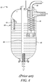
- a known oil tank system 42 is shown in Figure 4 .
- the known oil tank system 42 includes a de-aerator 44, which receives scavenged oil, which is aerated, and submits it to a de-aeration process in order to separate a majority of the air from the oil. This process may be achieved by inducing a vortex within the oil flow, the air that separates during the vortex then being released from the oil tank system 42 by a venting pipe 46. The deaerated oil can then pass out of the de-aerator 44 into an oil tank 48, from which it can be stored and then pumped out for use throughout an oil system (not shown).
- An oil level indicator 50 may be provided on the side of the oil tank 48, and may take the form of an indicator window 54, allowing an operator to view the level of oil within the oil tank 48.
- An electronic oil level sensor 56 is also provided, which provides an electronic measure of the oil level to an external device (not shown).
- oil tank with a larger capacity than known oil tanks.
- this larger capacity results in a significantly extended vertical extent of the oil tank, it has been noted that oil leaving the de-aerator and being deposited in the oil tank may fall a substantial distance from the de-aerator, depending on the oil level within the oil tank, resulting in agitation of the oil surface, partial reaeration of the oil, and an unrepresentative indicated oil level, which is undesirable.
- the present disclosure provides an oil tank, a gas turbine engine, and an aircraft as set out in the appended claims.
- an oil tank for a gas turbine engine comprising;
- the coiled portion may be configured to remove air from the oil, the body further comprising an air outlet for venting the air from the oil tank.
- the coiled portion may, in use, provide de-aeration of the oil entering the tank through the oil inlet.
- the air outlet may be located on an uppermost coil of the coiled portion.
- the coiled portion may be configured to impart angular acceleration to the oil received from the scavenge supply line.
- the coiled portion may be configured to receive oil directly from the scavenge supply line.
- the coiled portion may extend directly from the oil inlet.
- the coiled portion may extend directly to the oil outlet.
- the coiled portion may be formed as a helix or as a part-helix.
- the coiled portion may have coil axis that is oriented vertically or substantially vertically.
- coil axis it is meant the direction of extension of a non-planar coil, or the direction perpendicular to the plane of a planar coil. The orientation of the coil axis may be measured whilst the oil tank is in its standard position, by which we mean, for example, the position it is in when installed in a gas turbine engine or aircraft.
- a surface of the coiled portion may be configured to enhance oil adhesion.
- the surface of the coiled portion may comprise surface features for enhancing mechanical adhesion of oil to the surface.
- Such surface features may include micro-voids, channels, ridges, protrusions, or any other feature that is capable of increasing the adhesion of oil, in particular aviation oil.
- the size and shape of the surface features may be chosen to increase adhesion with a particular composition of oil.
- the surface of the coiled portion may comprise a material for enhancing dispersive adhesion of oil to the surface.
- the particular material chosen may be chosen to increase adhesion with a particular composition of oil.
- the oil tank may further comprise an air communication line between a first part of the oil tank and a second part of the oil tank.
- the first part of the oil tank and second part of the oil tank may each be a part of the coiled portion.
- the oil tank may further comprise an oil level sensor and/or an oil temperature sensor.
- the oil level sensor and/or the oil temperature sensor may be provided as a single unit within the oil tank.
- the oil level sensor and/or the oil temperature sensor may be provided on the air communication line.
- the oil tank for example the coiled portion, may be formed from standard piping.
- the size of the piping may correspond to British standards, American standards, International standards, or any standard known to those skilled in the art: ADME, ANSI, ASTM, AGA, API, AWWA, BC, ISO, DIN, etc.
- the coiled portion may be formed by coiling or bending pipe, for example standard piping, around a former. Other methods of bending may also be used.
- the coiled portion may have a slight freedom of movement in order to enhance absorption of vibration.
- This freedom may be provided by a flexible coupling of the coiled portion to the oil inlet, oil outlet, or another part of the oil tank.
- the freedom of movement may also be provided by providing spacing between adjacent coils of the coiled portion, such that they may move relative to one another.
- the freedom of movement may also be provided by non-rigid fixing of adjacent coils, for example allowing sliding movement between coils.
- oiled portion denotes a portion that is generally coil shaped or otherwise resembles a coil.
- a coiled portion of a body can be a part of the body that is wound into a shape that resembles a coil, for example a wound spiral so that oil passing through that part of the body follows a spiral course.
- a gas turbine engine for an aircraft comprising:
- the gas turbine engine may further comprise a gearbox that receives an input from the core shaft and outputs drive to the fan so as to drive the fan at a lower rotational speed than the core shaft.
- the oil tank may deliver oil to and/or scavenge oil, directly or indirectly, from the gearbox.
- the turbine may be a first turbine
- the compressor may be a first compressor
- the core shaft may be a first core shaft.
- the engine core may further comprise a second turbine, a second compressor, and a second core shaft connecting the second turbine to the second compressor.
- the second turbine, second compressor, and second core shaft may be arranged to rotate at a higher rotational speed than the first core shaft.
- an aircraft including a gas turbine engine according to the second aspect.
- Such a gas turbine engine may comprise an engine core comprising a turbine, a combustor, a compressor, and a core shaft connecting the turbine to the compressor.
- a gas turbine engine may comprise a fan (having fan blades) located upstream of the engine core.
- the gas turbine engine may comprise a gearbox that receives an input from the core shaft and outputs drive to the fan so as to drive the fan at a lower rotational speed than the core shaft.
- the input to the gearbox may be directly from the core shaft, or indirectly from the core shaft, for example via a spur shaft and/or gear.
- the core shaft may rigidly connect the turbine and the compressor, such that the turbine and compressor rotate at the same speed (with the fan rotating at a lower speed).
- the gas turbine engine as described and/or claimed herein may have any suitable general architecture.
- the gas turbine engine may have any desired number of shafts that connect turbines and compressors, for example one, two or three shafts.
- the turbine connected to the core shaft may be a first turbine
- the compressor connected to the core shaft may be a first compressor
- the core shaft may be a first core shaft.
- the engine core may further comprise a second turbine, a second compressor, and a second core shaft connecting the second turbine to the second compressor.
- the second turbine, second compressor, and second core shaft may be arranged to rotate at a higher rotational speed than the first core shaft.
- the second compressor may be positioned axially downstream of the first compressor.
- the second compressor may be arranged to receive (for example directly receive, for example via a generally annular duct) flow from the first compressor.
- the gearbox may be arranged to be driven by the core shaft that is configured to rotate (for example in use) at the lowest rotational speed (for example the first core shaft in the example above).
- the gearbox may be arranged to be driven only by the core shaft that is configured to rotate (for example in use) at the lowest rotational speed (for example only be the first core shaft, and not the second core shaft, in the example above).
- the gearbox may be arranged to be driven by any one or more shafts, for example the first and/or second shafts in the example above.
- the gearbox may be a reduction gearbox (in that the output to the fan is a lower rotational rate than the input from the core shaft). Any type of gearbox may be used.
- the gearbox may be a "planetary” or “star” gearbox, as described in more detail elsewhere herein.
- the gearbox may have any desired reduction ratio (defined as the rotational speed of the input shaft divided by the rotational speed of the output shaft), for example greater than 2.5, for example in the range of from 3 to 4.2, or 3.2 to 3.8, for example on the order of or at least 3, 3.1, 3.2, 3.3, 3.4, 3.5, 3.6, 3.7, 3.8, 3.9, 4, 4.1 or 4.2.
- the gear ratio may be, for example, between any two of the values in the previous sentence.
- the gearbox may be a "star” gearbox having a ratio in the range of from 3.1 or 3.2 to 3.8. In some arrangements, the gear ratio may be outside these ranges.
- a combustor may be provided axially downstream of the fan and compressor(s).
- the combustor may be directly downstream of (for example at the exit of) the second compressor, where a second compressor is provided.
- the flow at the exit to the combustor may be provided to the inlet of the second turbine, where a second turbine is provided.
- the combustor may be provided upstream of the turbine(s).
- each compressor may comprise any number of stages, for example multiple stages.
- Each stage may comprise a row of rotor blades and a row of stator vanes, which may be variable stator vanes (in that their angle of incidence may be variable).
- the row of rotor blades and the row of stator vanes may be axially offset from each other.
- each turbine may comprise any number of stages, for example multiple stages.
- Each stage may comprise a row of rotor blades and a row of stator vanes.
- the row of rotor blades and the row of stator vanes may be axially offset from each other.
- FIG. 1 illustrates a gas turbine engine 10 having a principal rotational axis 9.
- the engine 10 comprises an air intake 12 and a propulsive fan 23 that generates two airflows: a core airflow A and a bypass airflow B.
- the gas turbine engine 10 comprises a core 11 that receives the core airflow A.
- the engine core 11 comprises, in axial flow series, a low pressure compressor 14, a high-pressure compressor 15, combustion equipment 16, a high-pressure turbine 17, a low pressure turbine 19 and a core exhaust nozzle 20.
- a nacelle 21 surrounds the gas turbine engine 10 and defines a bypass duct 22 and a bypass exhaust nozzle 18.
- the bypass airflow B flows through the bypass duct 22.
- the fan 23 is attached to and driven by the low pressure turbine 19 via a shaft 26 and an epicyclic gearbox 30.
- the core airflow A is accelerated and compressed by the low pressure compressor 14 and directed into the high pressure compressor 15 where further compression takes place.
- the compressed air exhausted from the high pressure compressor 15 is directed into the combustion equipment 16 where it is mixed with fuel and the mixture is combusted.
- the resultant hot combustion products then expand through and thereby drive the high pressure and low pressure turbines 17, 19 before being exhausted through the nozzle 20 to provide some propulsive thrust.
- the high pressure turbine 17 drives the high pressure compressor 15 by a suitable interconnecting shaft 27.
- the fan 23 generally provides the majority of the propulsive thrust.
- the epicyclic gearbox 30 is a reduction gearbox.
- FIG. 2 An exemplary arrangement for a geared fan gas turbine engine 10 is shown in Figure 2 .
- the low pressure turbine 19 (see Figure 1 ) drives the shaft 26, which is coupled to a sun wheel, or sun gear, 28 of the epicyclic gear arrangement 30.
- a sun wheel, or sun gear, 28 of the epicyclic gear arrangement 30 Radially outwardly of the sun gear 28 and intermeshing therewith is a plurality of planet gears 32 that are coupled together by a planet carrier 34.
- the planet carrier 34 constrains the planet gears 32 to precess around the sun gear 28 in synchronicity whilst enabling each planet gear 32 to rotate about its own axis.
- the planet carrier 34 is coupled via linkages 36 to the fan 23 in order to drive its rotation about the engine axis 9.
- an annulus or ring gear 38 Radially outwardly of the planet gears 32 and intermeshing therewith is an annulus or ring gear 38 that is coupled, via linkages 40, to a stationary supporting structure 24.
- low pressure turbine and “low pressure compressor” as used herein may be taken to mean the lowest pressure turbine stages and lowest pressure compressor stages (i.e. not including the fan 23) respectively and/or the turbine and compressor stages that are connected together by the interconnecting shaft 26 with the lowest rotational speed in the engine (i.e. not including the gearbox output shaft that drives the fan 23).
- the "low pressure turbine” and “low pressure compressor” referred to herein may alternatively be known as the "intermediate pressure turbine” and “intermediate pressure compressor”. Where such alternative nomenclature is used, the fan 23 may be referred to as a first, or lowest pressure, compression stage.
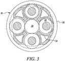
- the epicyclic gearbox 30 is shown by way of example in greater detail in Figure 3 .
- Each of the sun gear 28, planet gears 32 and ring gear 38 comprise teeth about their periphery to intermesh with the other gears. However, for clarity only exemplary portions of the teeth are illustrated in Figure 3 .
- Practical applications of a planetary epicyclic gearbox 30 generally comprise at least three planet gears 32.
- the epicyclic gearbox 30 illustrated by way of example in Figures 2 and 3 is of the planetary type, in that the planet carrier 34 is coupled to an output shaft via linkages 36, with the ring gear 38 fixed.
- the epicyclic gearbox 30 may be a star arrangement, in which the planet carrier 34 is held fixed, with the ring (or annulus) gear 38 allowed to rotate. In such an arrangement the fan 23 is driven by the ring gear 38.
- the gearbox 30 may be a differential gearbox in which the ring gear 38 and the planet carrier 34 are both allowed to rotate.
- any suitable arrangement may be used for locating the gearbox 30 in the engine 10 and/or for connecting the gearbox 30 to the engine 10.
- the connections (such as the linkages 36, 40 in the Figure 2 example) between the gearbox 30 and other parts of the engine 10 (such as the input shaft 26, the output shaft and the fixed structure 24) may have any desired degree of stiffness or flexibility.
- any suitable arrangement of the bearings between rotating and stationary parts of the engine may be used, and the disclosure is not limited to the exemplary arrangement of Figure 2 .
- the gearbox 30 has a star arrangement (described above)
- the skilled person would readily understand that the arrangement of output and support linkages and bearing locations would typically be different to that shown by way of example in Figure 2 .
- the present disclosure extends to a gas turbine engine having any arrangement of gearbox styles (for example star or planetary), support structures, input and output shaft arrangement, and bearing locations.
- gearbox styles for example star or planetary
- support structures for example star or planetary
- input and output shaft arrangement for example star or planetary
- bearing locations for example star or planetary
- the gearbox may drive additional and/or alternative components (e.g. the intermediate pressure compressor and/or a booster compressor).
- additional and/or alternative components e.g. the intermediate pressure compressor and/or a booster compressor.
- gas turbine engines to which the present disclosure may be applied may have alternative configurations.
- such engines may have an alternative number of compressors and/or turbines and/or an alternative number of interconnecting shafts.
- the gas turbine engine shown in Figure 1 has a split flow nozzle 18, 20 meaning that the flow through the bypass duct 22 has its own nozzle 18 that is separate to and radially outside the core engine nozzle 20.
- this is not limiting, and any aspect of the present disclosure may also apply to engines in which the flow through the bypass duct 22 and the flow through the core 11 are mixed, or combined, before (or upstream of) a single nozzle, which may be referred to as a mixed flow nozzle.
- One or both nozzles may have a fixed or variable area.
- the described example relates to a turbofan engine, the disclosure may apply, for example, to any type of gas turbine engine, such as an open rotor (in which the fan stage is not surrounded by a nacelle) or turboprop engine, for example.
- the gas turbine engine 10 may not comprise a gearbox 30.
- the geometry of the gas turbine engine 10, and components thereof, is defined by a conventional axis system, comprising an axial direction (which is aligned with the rotational axis 9), a radial direction (in the bottom-to-top direction in Figure 1 ), and a circumferential direction (perpendicular to the page in the Figure 1 view).
- the axial, radial and circumferential directions are mutually perpendicular.
- oil tank of the present disclosure that may be used in such a gas turbine engine.
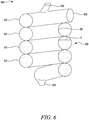
- FIG. 5 and Figure 6 show an embodiment of an oil tank 100 in accordance with the disclosure.
- the oil tank 100 receives scavenged oil from an oil system (not shown) via a scavenged oil supply inlet 102.
- the oil tank 100 includes an oil outlet 104 for delivery of oil back to the oil system, for example via an oil pump.
- the oil tank 100 is also shown in situ within the gas turbine engine in Figure 2 .
- the oil tank 100 comprises a body including a coiled portion 106 in the form of a helix that extends between the oil inlet 102 and the oil outlet 104.
- the coiled portion 106 therefore transfers oil from the oil inlet 102 to the level of the oil already held within the oil tank 100.
- the body therefore forms a flow path between the oil inlet and the oil outlet, the coiled portion 106 forming a part of the flow path.
- the coiled shape need not be perfectly helical and may vary in radius or curvature along its length.
- the scavenged oil may have a relatively large length of the oil tank 100 to travel in order to arrive at the oil level.
- the depicted coiled portion 106 provides a continuous gradient for the transmission of oil through the length of the oil tank 100.
- Other examples of oil tank may have a varying gradient along their length.
- the vertical drop of any oil in the oil tank 100 is therefore limited to the height of the cross-section of the coiled portion 106.
- due to the pressure of the oil entering from the scavenge line it is far more likely that oil will form a film on the interior walls of the coiled portion 106 and then drain in a controlled manner to the oil level within the oil tank 100.
- Air released from the oil during its passage through the oil tank 100 is able to rise due to its own buoyancy and exit the tank 100 via an air outlet 108 situated at the top of the oil tank 100.
- the air outlet 108 is depicted as being a channel leading off the uppermost coil of the coiled portion 106, but may also extend from a sidewall or from a lower coil, for example.
- the surface 110 of the interior of the oil tank 100 may be configured so as to enhance adhesion of oil. This configuration further helps to prevent aeration and ensuring that oil joining the oil level within the oil tank 100 does not act to overly agitate the surface.
- adhesion is considered to include all types of adhesion such as mechanical adhesion and dispersive adhesion, as well as any other mechanism by which oil can be encouraged to remain in contact with the surface of the oil tank 100.
- Mechanical adhesion may be enhanced through the use of particular surface features, patterns, etc.
- mechanical adhesion may be enhanced by the provision of channels, pores, ridges, protrusions, or undulations, either on the micro- or macro-scale, which act to keep the oil in adherence with the surface.
- the surface 110 may include materials that act to increase a dispersive adhesion with the particular composition of oil used within the oil tank and system.
- the coiled portion 106 of the oil tank 100 can act to limit movement of oil during short-term negative-G conditions.
- the coils 112 slow the movement of oil, delaying the onset of oil rising to the top of the oil tank 100. This will prolong the delivery of oil to the oil pump (not shown) situated in the oil system after the oil outlet 104 of the oil tank 100.
- the large surface area of the coiled portion 106 along with the large residence time granted by its shape, allows the coiled portion 106 to act as a de-aerator, removing the requirement for a separate de-aerator within the oil system. Despite this, an additional de-aerator may also be included within the oil system, if required.
- a benefit of the coiled portion 106 may be that loads incident on the oil tank 100, for example those resulting from a fan-blade off situation, can be absorbed to at least some extent by the natural spring action of the coiled portion 106. As well as absorbing one-time, irregular, or intermittent forces, the coiled portion 106 may also act to absorb more regular forces, such as those produced by vibrations within the engine and by other parts of the aircraft.
- a second embodiment of an oil tank 200 is shown in Figure 7 . Where features of the oil tank 200 are identical to those of the first oil tank 100, identical reference numerals are used.
- the oil tank 200 comprises a body including a coiled portion 206 and a lower tank portion 214.
- the lower tank portion 214 is, in the depicted example, the shape of a standard tank, acting as a storage container for the oil.
- the coiled portion 206 can carry out the de-aeration of oil and limit fall of the oil within the oil tank 200, whilst the lower tank portion 214 maximises the storage volume of the oil tank 200 below the coiled portion 206.
- the coiled portion 206 therefore feeds oil to the lower tank portion 214.
- the oil tank 200 of the second embodiment also includes two air communication lines 216.
- the air communication lines 216 interlink an upper part 218 of the coiled portion 206 with each of a lower part 220 of the coiled portion 206 and the lower tank portion 214. These act to provide an additional interconnection between the portions of the oil tank 200 and thus prevent the formation of air pockets within the oil tank 200.
- the air communication lines 216 therefore support the changes in oil level that may occur during changing engine operating conditions and changing oil consumption during a flight.
- sensors 222 such as oil level sensors and/or oil temperature sensors are included with the air communication lines 216 in order to allow monitoring of the oil level or oil temperature.
- the air communication lines 216 may run remotely from the oil tank 200 in order to provide easier access for a user to monitor temperatures or levels.
- Oil tanks within the scope of the disclosure may include multiple coiled portions, or may include coiled portions that are not directly connected to the oil inlet, i.e. there may be intervening oil tank parts, for example, but not limited to, filters or other oil tank portions.
Landscapes
- Engineering & Computer Science (AREA)
- General Engineering & Computer Science (AREA)
- Mechanical Engineering (AREA)
- Chemical & Material Sciences (AREA)
- Combustion & Propulsion (AREA)
- Aviation & Aerospace Engineering (AREA)
- Structures Of Non-Positive Displacement Pumps (AREA)
- General Details Of Gearings (AREA)
Abstract
An oil tank (100) for a gas turbine engine is provided. The oil tank (100) comprises an oil inlet (102), an oil outlet (104), and a body including a coiled portion (106) interposed between the oil inlet (102) and the oil outlet (104). Oil is received by the coiled portion (106). The coiled portion (106) acts to at least partially de-aerate oil received from the oil inlet (104).
Description
- The present disclosure relates to an oil tank for a gas turbine engine, and more particularly but not necessarily exclusively for a gas turbine engine comprising a gearbox. The present disclosure also relates to a gas turbine engine including an oil tank and an aircraft including a gas turbine engine including an oil tank.
- Oil tank systems, particularly those in aircraft, are used to store oil from a part of an oil system such that the oil may be recirculated throughout the system. Scavenge pumps are used to extract the oil, but this often results in a mixture of air and oil, being extracted by the scavenge pump and being fed to the oil tank system. A known
oil tank system 42 is shown inFigure 4 . - The known
oil tank system 42 includes ade-aerator 44, which receives scavenged oil, which is aerated, and submits it to a de-aeration process in order to separate a majority of the air from the oil. This process may be achieved by inducing a vortex within the oil flow, the air that separates during the vortex then being released from theoil tank system 42 by aventing pipe 46. The deaerated oil can then pass out of thede-aerator 44 into anoil tank 48, from which it can be stored and then pumped out for use throughout an oil system (not shown). Anoil level indicator 50 may be provided on the side of theoil tank 48, and may take the form of anindicator window 54, allowing an operator to view the level of oil within theoil tank 48. An electronicoil level sensor 56 is also provided, which provides an electronic measure of the oil level to an external device (not shown). - For various reasons, it may be required to provide an oil tank with a larger capacity than known oil tanks. Where this larger capacity results in a significantly extended vertical extent of the oil tank, it has been noted that oil leaving the de-aerator and being deposited in the oil tank may fall a substantial distance from the de-aerator, depending on the oil level within the oil tank, resulting in agitation of the oil surface, partial reaeration of the oil, and an unrepresentative indicated oil level, which is undesirable.
- It is therefore an object of the present invention to provide an improved oil tank in view of the above or at least to provide a useful alternative.
- The present disclosure provides an oil tank, a gas turbine engine, and an aircraft as set out in the appended claims.
- According to a first aspect, there is provided an oil tank for a gas turbine engine, the oil tank comprising;
- an oil inlet for receiving oil from a scavenge supply line;
- an oil outlet; and
- a body for transmitting and storing oil, the body defining a flow path between the oil inlet and the oil outlet;
- wherein the body includes a coiled portion that forms a part of the flow path and forms an outer wall of the oil tank.
- The coiled portion may be configured to remove air from the oil, the body further comprising an air outlet for venting the air from the oil tank.
- The coiled portion may, in use, provide de-aeration of the oil entering the tank through the oil inlet.
- The air outlet may be located on an uppermost coil of the coiled portion.
- The coiled portion may be configured to impart angular acceleration to the oil received from the scavenge supply line.
- The coiled portion may be configured to receive oil directly from the scavenge supply line.
- The coiled portion may extend directly from the oil inlet.
- The coiled portion may extend directly to the oil outlet.
- The coiled portion may be formed as a helix or as a part-helix.
- The coiled portion may have coil axis that is oriented vertically or substantially vertically. By "coil axis", it is meant the direction of extension of a non-planar coil, or the direction perpendicular to the plane of a planar coil. The orientation of the coil axis may be measured whilst the oil tank is in its standard position, by which we mean, for example, the position it is in when installed in a gas turbine engine or aircraft.
- A surface of the coiled portion may be configured to enhance oil adhesion.
- The surface of the coiled portion may comprise surface features for enhancing mechanical adhesion of oil to the surface. Such surface features may include micro-voids, channels, ridges, protrusions, or any other feature that is capable of increasing the adhesion of oil, in particular aviation oil. The size and shape of the surface features may be chosen to increase adhesion with a particular composition of oil.
- The surface of the coiled portion may comprise a material for enhancing dispersive adhesion of oil to the surface. The particular material chosen may be chosen to increase adhesion with a particular composition of oil.
- The oil tank may further comprise an air communication line between a first part of the oil tank and a second part of the oil tank.
- The first part of the oil tank and second part of the oil tank may each be a part of the coiled portion.
- The oil tank may further comprise an oil level sensor and/or an oil temperature sensor.
- The oil level sensor and/or the oil temperature sensor may be provided as a single unit within the oil tank.
- The oil level sensor and/or the oil temperature sensor may be provided on the air communication line.
- The oil tank, for example the coiled portion, may be formed from standard piping. For example, the size of the piping may correspond to British standards, American standards, International standards, or any standard known to those skilled in the art: ADME, ANSI, ASTM, AGA, API, AWWA, BC, ISO, DIN, etc.
- The coiled portion may be formed by coiling or bending pipe, for example standard piping, around a former. Other methods of bending may also be used.
- The coiled portion may have a slight freedom of movement in order to enhance absorption of vibration. This freedom may be provided by a flexible coupling of the coiled portion to the oil inlet, oil outlet, or another part of the oil tank. The freedom of movement may also be provided by providing spacing between adjacent coils of the coiled portion, such that they may move relative to one another. The freedom of movement may also be provided by non-rigid fixing of adjacent coils, for example allowing sliding movement between coils.
- "Coiled portion" as used herein denotes a portion that is generally coil shaped or otherwise resembles a coil. For example a coiled portion of a body can be a part of the body that is wound into a shape that resembles a coil, for example a wound spiral so that oil passing through that part of the body follows a spiral course.
- According to a second aspect, there is provided a gas turbine engine for an aircraft, the gas turbine engine comprising:
- an engine core comprising a turbine, a compressor, and a core shaft connecting the turbine to the compressor;
- a fan located upstream of the engine core, the fan comprising a plurality of fan blades; and
- an oil tank according to the first aspect.
- The gas turbine engine may further comprise a gearbox that receives an input from the core shaft and outputs drive to the fan so as to drive the fan at a lower rotational speed than the core shaft.
- The oil tank may deliver oil to and/or scavenge oil, directly or indirectly, from the gearbox.
- The turbine may be a first turbine, the compressor may be a first compressor, and the core shaft may be a first core shaft.
- The engine core may further comprise a second turbine, a second compressor, and a second core shaft connecting the second turbine to the second compressor.
- The second turbine, second compressor, and second core shaft may be arranged to rotate at a higher rotational speed than the first core shaft.
- According to a third aspect, there is provided an aircraft including a gas turbine engine according to the second aspect.
- Embodiments will now be described by way of example only, with reference to the Figures, in which:
-
Figure 1 is a sectional side view of a gas turbine engine; -
Figure 2 is a close up sectional side view of an upstream portion of a gas turbine engine; -
Figure 3 is a partially cut-away view of a gearbox for a gas turbine engine; -
Figure 4 is a sectional view of a known oil tank; -
Figure 5 is an embodiment of an oil tank in accordance with the disclosure; -
Figure 6 is a cross-sectional view of the oil tank ofFigure 5 , showing the oil level; and -
Figure 7 is a second embodiment of an oil tank in accordance with the disclosure. - As noted elsewhere herein, the present disclosure may relate to a gas turbine engine. Such a gas turbine engine may comprise an engine core comprising a turbine, a combustor, a compressor, and a core shaft connecting the turbine to the compressor. Such a gas turbine engine may comprise a fan (having fan blades) located upstream of the engine core.
- Arrangements of the present disclosure may be particularly, although not exclusively, beneficial for fans that are driven via a gearbox. Accordingly, the gas turbine engine may comprise a gearbox that receives an input from the core shaft and outputs drive to the fan so as to drive the fan at a lower rotational speed than the core shaft. The input to the gearbox may be directly from the core shaft, or indirectly from the core shaft, for example via a spur shaft and/or gear. The core shaft may rigidly connect the turbine and the compressor, such that the turbine and compressor rotate at the same speed (with the fan rotating at a lower speed).
- The gas turbine engine as described and/or claimed herein may have any suitable general architecture. For example, the gas turbine engine may have any desired number of shafts that connect turbines and compressors, for example one, two or three shafts. Purely by way of example, the turbine connected to the core shaft may be a first turbine, the compressor connected to the core shaft may be a first compressor, and the core shaft may be a first core shaft. The engine core may further comprise a second turbine, a second compressor, and a second core shaft connecting the second turbine to the second compressor. The second turbine, second compressor, and second core shaft may be arranged to rotate at a higher rotational speed than the first core shaft.
- In such an arrangement, the second compressor may be positioned axially downstream of the first compressor. The second compressor may be arranged to receive (for example directly receive, for example via a generally annular duct) flow from the first compressor.
- The gearbox may be arranged to be driven by the core shaft that is configured to rotate (for example in use) at the lowest rotational speed (for example the first core shaft in the example above). For example, the gearbox may be arranged to be driven only by the core shaft that is configured to rotate (for example in use) at the lowest rotational speed (for example only be the first core shaft, and not the second core shaft, in the example above). Alternatively, the gearbox may be arranged to be driven by any one or more shafts, for example the first and/or second shafts in the example above.
- The gearbox may be a reduction gearbox (in that the output to the fan is a lower rotational rate than the input from the core shaft). Any type of gearbox may be used. For example, the gearbox may be a "planetary" or "star" gearbox, as described in more detail elsewhere herein. The gearbox may have any desired reduction ratio (defined as the rotational speed of the input shaft divided by the rotational speed of the output shaft), for example greater than 2.5, for example in the range of from 3 to 4.2, or 3.2 to 3.8, for example on the order of or at least 3, 3.1, 3.2, 3.3, 3.4, 3.5, 3.6, 3.7, 3.8, 3.9, 4, 4.1 or 4.2. The gear ratio may be, for example, between any two of the values in the previous sentence. Purely by way of example, the gearbox may be a "star" gearbox having a ratio in the range of from 3.1 or 3.2 to 3.8. In some arrangements, the gear ratio may be outside these ranges.
- In any gas turbine engine as described and/or claimed herein, a combustor may be provided axially downstream of the fan and compressor(s). For example, the combustor may be directly downstream of (for example at the exit of) the second compressor, where a second compressor is provided. By way of further example, the flow at the exit to the combustor may be provided to the inlet of the second turbine, where a second turbine is provided. The combustor may be provided upstream of the turbine(s).
- The or each compressor (for example the first compressor and second compressor as described above) may comprise any number of stages, for example multiple stages. Each stage may comprise a row of rotor blades and a row of stator vanes, which may be variable stator vanes (in that their angle of incidence may be variable). The row of rotor blades and the row of stator vanes may be axially offset from each other.
- The or each turbine (for example the first turbine and second turbine as described above) may comprise any number of stages, for example multiple stages. Each stage may comprise a row of rotor blades and a row of stator vanes. The row of rotor blades and the row of stator vanes may be axially offset from each other.
- The skilled person will appreciate that except where mutually exclusive, a feature or parameter described in relation to any one of the above aspects may be applied to any other aspect. Furthermore, except where mutually exclusive, any feature or parameter described herein may be applied to any aspect and/or combined with any other feature or parameter described herein.
- Embodiments will now be described by way of example only, with reference to the Figures.
-
Figure 1 illustrates agas turbine engine 10 having a principalrotational axis 9. Theengine 10 comprises anair intake 12 and apropulsive fan 23 that generates two airflows: a core airflow A and a bypass airflow B. Thegas turbine engine 10 comprises a core 11 that receives the core airflow A. Theengine core 11 comprises, in axial flow series, alow pressure compressor 14, a high-pressure compressor 15,combustion equipment 16, a high-pressure turbine 17, alow pressure turbine 19 and acore exhaust nozzle 20. Anacelle 21 surrounds thegas turbine engine 10 and defines abypass duct 22 and abypass exhaust nozzle 18. The bypass airflow B flows through thebypass duct 22. Thefan 23 is attached to and driven by thelow pressure turbine 19 via ashaft 26 and anepicyclic gearbox 30. - In use, the core airflow A is accelerated and compressed by the
low pressure compressor 14 and directed into thehigh pressure compressor 15 where further compression takes place. The compressed air exhausted from thehigh pressure compressor 15 is directed into thecombustion equipment 16 where it is mixed with fuel and the mixture is combusted. The resultant hot combustion products then expand through and thereby drive the high pressure andlow pressure turbines nozzle 20 to provide some propulsive thrust. Thehigh pressure turbine 17 drives thehigh pressure compressor 15 by a suitable interconnectingshaft 27. Thefan 23 generally provides the majority of the propulsive thrust. Theepicyclic gearbox 30 is a reduction gearbox. - An exemplary arrangement for a geared fan
gas turbine engine 10 is shown inFigure 2 . The low pressure turbine 19 (seeFigure 1 ) drives theshaft 26, which is coupled to a sun wheel, or sun gear, 28 of theepicyclic gear arrangement 30. Radially outwardly of thesun gear 28 and intermeshing therewith is a plurality of planet gears 32 that are coupled together by aplanet carrier 34. Theplanet carrier 34 constrains the planet gears 32 to precess around thesun gear 28 in synchronicity whilst enabling eachplanet gear 32 to rotate about its own axis. Theplanet carrier 34 is coupled vialinkages 36 to thefan 23 in order to drive its rotation about theengine axis 9. Radially outwardly of the planet gears 32 and intermeshing therewith is an annulus orring gear 38 that is coupled, vialinkages 40, to a stationary supportingstructure 24. - Note that the terms "low pressure turbine" and "low pressure compressor" as used herein may be taken to mean the lowest pressure turbine stages and lowest pressure compressor stages (i.e. not including the fan 23) respectively and/or the turbine and compressor stages that are connected together by the interconnecting
shaft 26 with the lowest rotational speed in the engine (i.e. not including the gearbox output shaft that drives the fan 23). In some literature, the "low pressure turbine" and "low pressure compressor" referred to herein may alternatively be known as the "intermediate pressure turbine" and "intermediate pressure compressor". Where such alternative nomenclature is used, thefan 23 may be referred to as a first, or lowest pressure, compression stage. - The
epicyclic gearbox 30 is shown by way of example in greater detail inFigure 3 . Each of thesun gear 28, planet gears 32 andring gear 38 comprise teeth about their periphery to intermesh with the other gears. However, for clarity only exemplary portions of the teeth are illustrated inFigure 3 . There are fourplanet gears 32 illustrated, although it will be apparent to the skilled reader that more or fewer planet gears 32 may be provided within the scope of the claimed invention. Practical applications of a planetaryepicyclic gearbox 30 generally comprise at least three planet gears 32. - The
epicyclic gearbox 30 illustrated by way of example inFigures 2 and3 is of the planetary type, in that theplanet carrier 34 is coupled to an output shaft vialinkages 36, with thering gear 38 fixed. However, any other suitable type ofepicyclic gearbox 30 may be used. By way of further example, theepicyclic gearbox 30 may be a star arrangement, in which theplanet carrier 34 is held fixed, with the ring (or annulus)gear 38 allowed to rotate. In such an arrangement thefan 23 is driven by thering gear 38. By way of further alternative example, thegearbox 30 may be a differential gearbox in which thering gear 38 and theplanet carrier 34 are both allowed to rotate. - It will be appreciated that the arrangement shown in
Figures 2 and3 is by way of example only, and various alternatives are within the scope of the present disclosure. Purely by way of example, any suitable arrangement may be used for locating thegearbox 30 in theengine 10 and/or for connecting thegearbox 30 to theengine 10. By way of further example, the connections (such as thelinkages Figure 2 example) between thegearbox 30 and other parts of the engine 10 (such as theinput shaft 26, the output shaft and the fixed structure 24) may have any desired degree of stiffness or flexibility. By way of further example, any suitable arrangement of the bearings between rotating and stationary parts of the engine (for example between the input and output shafts from the gearbox and the fixed structures, such as the gearbox casing) may be used, and the disclosure is not limited to the exemplary arrangement ofFigure 2 . For example, where thegearbox 30 has a star arrangement (described above), the skilled person would readily understand that the arrangement of output and support linkages and bearing locations would typically be different to that shown by way of example inFigure 2 . - Accordingly, the present disclosure extends to a gas turbine engine having any arrangement of gearbox styles (for example star or planetary), support structures, input and output shaft arrangement, and bearing locations.
- Optionally, the gearbox may drive additional and/or alternative components (e.g. the intermediate pressure compressor and/or a booster compressor).
- Other gas turbine engines to which the present disclosure may be applied may have alternative configurations. For example, such engines may have an alternative number of compressors and/or turbines and/or an alternative number of interconnecting shafts. By way of further example, the gas turbine engine shown in
Figure 1 has asplit flow nozzle bypass duct 22 has itsown nozzle 18 that is separate to and radially outside thecore engine nozzle 20. However, this is not limiting, and any aspect of the present disclosure may also apply to engines in which the flow through thebypass duct 22 and the flow through the core 11 are mixed, or combined, before (or upstream of) a single nozzle, which may be referred to as a mixed flow nozzle. One or both nozzles (whether mixed or split flow) may have a fixed or variable area. Whilst the described example relates to a turbofan engine, the disclosure may apply, for example, to any type of gas turbine engine, such as an open rotor (in which the fan stage is not surrounded by a nacelle) or turboprop engine, for example. In some arrangements, thegas turbine engine 10 may not comprise agearbox 30. - The geometry of the
gas turbine engine 10, and components thereof, is defined by a conventional axis system, comprising an axial direction (which is aligned with the rotational axis 9), a radial direction (in the bottom-to-top direction inFigure 1 ), and a circumferential direction (perpendicular to the page in theFigure 1 view). The axial, radial and circumferential directions are mutually perpendicular. - Turning now more specifically to the oil tank of the present disclosure that may be used in such a gas turbine engine.
-
Figure 5 andFigure 6 show an embodiment of anoil tank 100 in accordance with the disclosure. Theoil tank 100 receives scavenged oil from an oil system (not shown) via a scavengedoil supply inlet 102. Theoil tank 100 includes anoil outlet 104 for delivery of oil back to the oil system, for example via an oil pump. Theoil tank 100 is also shown in situ within the gas turbine engine inFigure 2 . - The
oil tank 100 comprises a body including a coiledportion 106 in the form of a helix that extends between theoil inlet 102 and theoil outlet 104. The coiledportion 106 therefore transfers oil from theoil inlet 102 to the level of the oil already held within theoil tank 100. The body therefore forms a flow path between the oil inlet and the oil outlet, the coiledportion 106 forming a part of the flow path. Although described in relation to the depicted embodiment as a helix, the coiled shape need not be perfectly helical and may vary in radius or curvature along its length. - As the
oil tank 100 is elongate, having a large vertical extent compared to its horizontal extent, if the oil level, L, is relatively low, the scavenged oil may have a relatively large length of theoil tank 100 to travel in order to arrive at the oil level. In order to limit oil surface agitation and aeration of the oil during this travel - or an even longer travel if the level of the oil is within the oil tank 100 - the depictedcoiled portion 106 provides a continuous gradient for the transmission of oil through the length of theoil tank 100. Other examples of oil tank may have a varying gradient along their length. - The vertical drop of any oil in the
oil tank 100 is therefore limited to the height of the cross-section of the coiledportion 106. However, due to the pressure of the oil entering from the scavenge line, it is far more likely that oil will form a film on the interior walls of the coiledportion 106 and then drain in a controlled manner to the oil level within theoil tank 100. Air released from the oil during its passage through theoil tank 100 is able to rise due to its own buoyancy and exit thetank 100 via anair outlet 108 situated at the top of theoil tank 100. Theair outlet 108 is depicted as being a channel leading off the uppermost coil of the coiledportion 106, but may also extend from a sidewall or from a lower coil, for example. - The
surface 110 of the interior of theoil tank 100, including the coiledportion 106, may be configured so as to enhance adhesion of oil. This configuration further helps to prevent aeration and ensuring that oil joining the oil level within theoil tank 100 does not act to overly agitate the surface. - The term adhesion is considered to include all types of adhesion such as mechanical adhesion and dispersive adhesion, as well as any other mechanism by which oil can be encouraged to remain in contact with the surface of the
oil tank 100. - Mechanical adhesion may be enhanced through the use of particular surface features, patterns, etc. For example, mechanical adhesion may be enhanced by the provision of channels, pores, ridges, protrusions, or undulations, either on the micro- or macro-scale, which act to keep the oil in adherence with the surface.
- Alternatively or additionally, the
surface 110 may include materials that act to increase a dispersive adhesion with the particular composition of oil used within the oil tank and system. - In addition, the coiled
portion 106 of theoil tank 100 can act to limit movement of oil during short-term negative-G conditions. Thecoils 112 slow the movement of oil, delaying the onset of oil rising to the top of theoil tank 100. This will prolong the delivery of oil to the oil pump (not shown) situated in the oil system after theoil outlet 104 of theoil tank 100. - The large surface area of the coiled
portion 106, along with the large residence time granted by its shape, allows the coiledportion 106 to act as a de-aerator, removing the requirement for a separate de-aerator within the oil system. Despite this, an additional de-aerator may also be included within the oil system, if required. - A benefit of the coiled
portion 106 may be that loads incident on theoil tank 100, for example those resulting from a fan-blade off situation, can be absorbed to at least some extent by the natural spring action of the coiledportion 106. As well as absorbing one-time, irregular, or intermittent forces, the coiledportion 106 may also act to absorb more regular forces, such as those produced by vibrations within the engine and by other parts of the aircraft. - A second embodiment of an
oil tank 200 is shown inFigure 7 . Where features of theoil tank 200 are identical to those of thefirst oil tank 100, identical reference numerals are used. - The
oil tank 200 comprises a body including a coiledportion 206 and alower tank portion 214. Thelower tank portion 214 is, in the depicted example, the shape of a standard tank, acting as a storage container for the oil. By providing theoil tank 200 in this manner, the coiledportion 206 can carry out the de-aeration of oil and limit fall of the oil within theoil tank 200, whilst thelower tank portion 214 maximises the storage volume of theoil tank 200 below the coiledportion 206. The coiledportion 206 therefore feeds oil to thelower tank portion 214. - The
oil tank 200 of the second embodiment also includes two air communication lines 216. Theair communication lines 216 interlink anupper part 218 of the coiledportion 206 with each of alower part 220 of the coiledportion 206 and thelower tank portion 214. These act to provide an additional interconnection between the portions of theoil tank 200 and thus prevent the formation of air pockets within theoil tank 200. Theair communication lines 216 therefore support the changes in oil level that may occur during changing engine operating conditions and changing oil consumption during a flight. - Moreover,
sensors 222 such as oil level sensors and/or oil temperature sensors are included with theair communication lines 216 in order to allow monitoring of the oil level or oil temperature. Theair communication lines 216 may run remotely from theoil tank 200 in order to provide easier access for a user to monitor temperatures or levels. - Oil tanks within the scope of the disclosure may include multiple coiled portions, or may include coiled portions that are not directly connected to the oil inlet, i.e. there may be intervening oil tank parts, for example, but not limited to, filters or other oil tank portions.
- It will be understood that the invention is not limited to the embodiments above-described and various modifications and improvements can be made without departing from the concepts described herein. Except where mutually exclusive, any of the features may be employed separately or in combination with any other features and the disclosure extends to and includes all combinations and sub-combinations of one or more features described herein within the scope of the appended claims.
Claims (15)
- An oil tank (100; 200) for a gas turbine engine, the oil tank (100; 200) comprising:an oil inlet (102) for receiving oil from a scavenge supply line;an oil outlet (104); anda body for transmitting and storing oil, the body defining a flow path between the oil inlet (102) and the oil outlet (104);wherein the body includes a coiled portion (106; 206) that forms a part of the flow path and an outer wall of the oil tank (100; 200).
- An oil tank (100; 200) according to claim 1, wherein the coiled portion (106; 206) is configured to remove air from the oil, the body further comprising an air outlet (108) for venting the air from the oil tank (100; 200).
- An oil tank (100; 200) according to claim 2, wherein the air outlet (108) is located on an uppermost coil of the coiled portion (106; 206).
- An oil tank (100; 200) according to any preceding claim, wherein the coiled portion (106; 206) is configured to impart angular acceleration to the oil received from the scavenge supply line.
- An oil tank (100; 200) according to any preceding claim, wherein the coiled portion (106; 206) is configured to receive oil directly from the scavenge supply line.
- An oil tank (100; 200) according to any preceding claim, wherein the coiled portion (106; 206) extends directly from the oil inlet (102) and/or directly to the oil outlet (104).
- An oil tank (100; 200) according to any preceding claim, wherein the coiled portion (106; 206) is formed as a helix or part-helix.
- An oil tank (100; 200) according to any preceding claim, wherein the coiled portion (106; 206) has a coil axis that is oriented vertically or substantially vertically.
- An oil tank (200) according to any preceding claim, further comprising an air communication line (216) between a first part (218) of the oil tank (200) and a second part (214, 220) of the oil tank (200).
- An oil tank (200) according to claim 9, wherein the first part (218) of the oil tank (200) and the second part (220) of the oil tank (200) are each a part of the coiled portion (206).
- An oil tank (200) according to any preceding claim, further comprising an oil level sensor and/or an oil temperature sensor, and the oil level sensor and/or oil temperature sensor are/is provided on the air communication line (216).
- A gas turbine engine (10) for an aircraft, the gas turbine engine (10) comprising:an engine core (11) comprising a turbine (19), a compressor (14), and a core shaft (26) connecting the turbine to the compressor;a fan (23) located upstream of the engine core, the fan comprising a plurality of fan blades; andan oil tank (100; 200) according to any preceding claim.
- A gas turbine engine (10) according to claim 12, further comprising a gearbox (30) that receives an input from the core shaft (26) and outputs drive to the fan so as to drive the fan at a lower rotational speed than the core shaft.
- A gas turbine engine (10) according to claim 12 or claim 13, wherein the oil tank (100; 200) is configured to deliver oil to and/or scavenge oil, directly or indirectly, from the gearbox (30).
- An aircraft including a gas turbine engine according to any one of claims 12 to 14.
Applications Claiming Priority (1)
| Application Number | Priority Date | Filing Date | Title |
|---|---|---|---|
| GBGB1807266.0A GB201807266D0 (en) | 2018-05-03 | 2018-05-03 | Oil tank |
Publications (1)
| Publication Number | Publication Date |
|---|---|
| EP3564510A1 true EP3564510A1 (en) | 2019-11-06 |
Family
ID=62598266
Family Applications (1)
| Application Number | Title | Priority Date | Filing Date |
|---|---|---|---|
| EP19167055.3A Withdrawn EP3564510A1 (en) | 2018-05-03 | 2019-04-03 | Oil tank including a de-aerator |
Country Status (4)
| Country | Link |
|---|---|
| US (1) | US11174787B2 (en) |
| EP (1) | EP3564510A1 (en) |
| CN (1) | CN110435904A (en) |
| GB (1) | GB201807266D0 (en) |
Families Citing this family (10)
| Publication number | Priority date | Publication date | Assignee | Title |
|---|---|---|---|---|
| GB201805930D0 (en) * | 2018-04-10 | 2018-05-23 | Rolls Royce Plc | Tank Assembly |
| US11174916B2 (en) | 2019-03-21 | 2021-11-16 | Pratt & Whitney Canada Corp. | Aircraft engine reduction gearbox |
| US11530617B2 (en) * | 2020-10-26 | 2022-12-20 | Antheon Research, Inc. | Gas turbine propulsion system |
| IT202100003647A1 (en) * | 2021-02-17 | 2022-08-17 | Nuovo Pignone Tecnologie Srl | FLOODING CONTAINMENT TANK |
| US11268453B1 (en) | 2021-03-17 | 2022-03-08 | Pratt & Whitney Canada Corp. | Lubrication system for aircraft engine reduction gearbox |
| US11674406B2 (en) | 2021-08-06 | 2023-06-13 | Pratt & Whitney Canada Corp. | Variable gap between impeller rotor and static structure |
| US11719243B2 (en) | 2021-08-06 | 2023-08-08 | Pratt & Whitney Canada Corp. | Impeller rotor configured with wear resistant seal land |
| US12448919B2 (en) * | 2023-06-08 | 2025-10-21 | Pratt & Whitney Canada Corp. | Aircraft engine oil distribution system |
| US12590551B1 (en) * | 2024-09-25 | 2026-03-31 | Pratt & Whitney Canada Corp. | Oil tank return for an aircraft engine oil system |
| US12510082B1 (en) * | 2024-11-01 | 2025-12-30 | Pratt & Whitney Canada Corp. | Impeller rotor seal runner with divergent guide surface |
Citations (3)
| Publication number | Priority date | Publication date | Assignee | Title |
|---|---|---|---|---|
| GB642621A (en) * | 1945-06-02 | 1950-09-06 | Lockheed Aircraft Corp | Improvements in or relating to an internal combustion turbine |
| EP2166196A2 (en) * | 2008-09-18 | 2010-03-24 | United Technologies Corporation | Continuous supply oil tank for zero and negative G operation |
| CA2861179A1 (en) * | 2013-12-20 | 2015-06-20 | Pratt & Whitney Canada Corp. | Oil tank and scavenge pipe assembly of a gas turbine engine and method of delivering an oil and air mixture to same |
Family Cites Families (4)
| Publication number | Priority date | Publication date | Assignee | Title |
|---|---|---|---|---|
| US6279555B1 (en) | 2000-08-31 | 2001-08-28 | Caterpillar Inc. | Blow-by gas evacuation and oil reclamation |
| US7677228B2 (en) | 2007-11-16 | 2010-03-16 | Manookian Jr Arman | Crankcase vapor purification device |
| FR2980238B1 (en) * | 2011-09-20 | 2013-09-20 | Snecma | METHOD AND DEVICE FOR DETECTION OF CONTAMINATION OF THE OIL CIRCUIT OF A TURBOJET ENGINE BY FUEL |
| US10578020B2 (en) * | 2015-07-21 | 2020-03-03 | Unison Industries, Llc | Integral oil tank heat exchanger |
-
2018
- 2018-05-03 GB GBGB1807266.0A patent/GB201807266D0/en not_active Ceased
-
2019
- 2019-04-03 EP EP19167055.3A patent/EP3564510A1/en not_active Withdrawn
- 2019-04-19 US US16/389,190 patent/US11174787B2/en active Active
- 2019-04-29 CN CN201910354554.4A patent/CN110435904A/en active Pending
Patent Citations (3)
| Publication number | Priority date | Publication date | Assignee | Title |
|---|---|---|---|---|
| GB642621A (en) * | 1945-06-02 | 1950-09-06 | Lockheed Aircraft Corp | Improvements in or relating to an internal combustion turbine |
| EP2166196A2 (en) * | 2008-09-18 | 2010-03-24 | United Technologies Corporation | Continuous supply oil tank for zero and negative G operation |
| CA2861179A1 (en) * | 2013-12-20 | 2015-06-20 | Pratt & Whitney Canada Corp. | Oil tank and scavenge pipe assembly of a gas turbine engine and method of delivering an oil and air mixture to same |
Also Published As
| Publication number | Publication date |
|---|---|
| CN110435904A (en) | 2019-11-12 |
| US11174787B2 (en) | 2021-11-16 |
| US20190338705A1 (en) | 2019-11-07 |
| GB201807266D0 (en) | 2018-06-20 |
Similar Documents
| Publication | Publication Date | Title |
|---|---|---|
| US11174787B2 (en) | Oil tank | |
| US11492927B2 (en) | Oil tank system | |
| CN111120101B (en) | gas turbine engine | |
| EP3564498B1 (en) | Turbofan engine with oil tank filling system | |
| CN110295999B (en) | Gas turbine engine and oil system thereof | |
| EP3933181A1 (en) | High thrust geared gas turbine engine | |
| US11156124B2 (en) | Oil tank filling system | |
| EP3034850A1 (en) | Planetary gear system for turbomachine | |
| US12421898B2 (en) | Gearbox assembly with lubricant extraction volume ratio | |
| EP4224002B1 (en) | Power takeoff transmission | |
| WO2014197075A2 (en) | Thrust efficient turbofan engine | |
| US11174755B2 (en) | Oil tank filling system | |
| US20200232343A1 (en) | Oil scavenge system | |
| US20250361821A1 (en) | Integrated in-line emergency lube pump assembly for planetary gearbox configurations | |
| CN110486167A (en) | Gas-turbine engines | |
| CN110435903B (en) | Oil tank filling system | |
| CN110388336A (en) | Gas-turbine engines inner cylinder | |
| US20230203992A1 (en) | Gas turbine engine of an aircraft comprising a transmission | |
| EP3696379A1 (en) | A thermal management system and a gas turbine engine | |
| EP3677751A1 (en) | Gas turbine engine bifurcation | |
| EP3553359A1 (en) | Joint | |
| EP3163033A1 (en) | Gas turbine engine with high speed low pressure turbine section and bearing support features | |
| EP3163062A1 (en) | Gas turbine engine with high speed low pressure turbine section and bearing support features |
Legal Events
| Date | Code | Title | Description |
|---|---|---|---|
| PUAI | Public reference made under article 153(3) epc to a published international application that has entered the european phase |
Free format text: ORIGINAL CODE: 0009012 |
|
| STAA | Information on the status of an ep patent application or granted ep patent |
Free format text: STATUS: THE APPLICATION HAS BEEN PUBLISHED |
|
| AK | Designated contracting states |
Kind code of ref document: A1 Designated state(s): AL AT BE BG CH CY CZ DE DK EE ES FI FR GB GR HR HU IE IS IT LI LT LU LV MC MK MT NL NO PL PT RO RS SE SI SK SM TR |
|
| AX | Request for extension of the european patent |
Extension state: BA ME |
|
| RAP1 | Party data changed (applicant data changed or rights of an application transferred) |
Owner name: ROLLS-ROYCE PLC |
|
| STAA | Information on the status of an ep patent application or granted ep patent |
Free format text: STATUS: THE APPLICATION IS DEEMED TO BE WITHDRAWN |
|
| 18D | Application deemed to be withdrawn |
Effective date: 20200603 |