EP3564485A1 - Airfoils, cores, and methods of manufacture for forming airfoils having fluidly connected platform cooling circuits - Google Patents
Airfoils, cores, and methods of manufacture for forming airfoils having fluidly connected platform cooling circuits Download PDFInfo
- Publication number
- EP3564485A1 EP3564485A1 EP19169644.2A EP19169644A EP3564485A1 EP 3564485 A1 EP3564485 A1 EP 3564485A1 EP 19169644 A EP19169644 A EP 19169644A EP 3564485 A1 EP3564485 A1 EP 3564485A1
- Authority
- EP
- European Patent Office
- Prior art keywords
- platform
- core
- airfoil
- main body
- feed cavity
- Prior art date
- Legal status (The legal status is an assumption and is not a legal conclusion. Google has not performed a legal analysis and makes no representation as to the accuracy of the status listed.)
- Granted
Links
Images







Classifications
-
- F—MECHANICAL ENGINEERING; LIGHTING; HEATING; WEAPONS; BLASTING
- F01—MACHINES OR ENGINES IN GENERAL; ENGINE PLANTS IN GENERAL; STEAM ENGINES
- F01D—NON-POSITIVE DISPLACEMENT MACHINES OR ENGINES, e.g. STEAM TURBINES
- F01D5/00—Blades; Blade-carrying members; Heating, heat-insulating, cooling or antivibration means on the blades or the members
- F01D5/12—Blades
- F01D5/14—Form or construction
- F01D5/18—Hollow blades, i.e. blades with cooling or heating channels or cavities; Heating, heat-insulating or cooling means on blades
- F01D5/186—Film cooling
-
- B—PERFORMING OPERATIONS; TRANSPORTING
- B22—CASTING; POWDER METALLURGY
- B22C—FOUNDRY MOULDING
- B22C9/00—Moulds or cores; Moulding processes
- B22C9/10—Cores; Manufacture or installation of cores
-
- B—PERFORMING OPERATIONS; TRANSPORTING
- B22—CASTING; POWDER METALLURGY
- B22C—FOUNDRY MOULDING
- B22C9/00—Moulds or cores; Moulding processes
- B22C9/10—Cores; Manufacture or installation of cores
- B22C9/103—Multipart cores
-
- B—PERFORMING OPERATIONS; TRANSPORTING
- B22—CASTING; POWDER METALLURGY
- B22C—FOUNDRY MOULDING
- B22C9/00—Moulds or cores; Moulding processes
- B22C9/22—Moulds for peculiarly-shaped castings
- B22C9/24—Moulds for peculiarly-shaped castings for hollow articles
-
- B—PERFORMING OPERATIONS; TRANSPORTING
- B22—CASTING; POWDER METALLURGY
- B22D—CASTING OF METALS; CASTING OF OTHER SUBSTANCES BY THE SAME PROCESSES OR DEVICES
- B22D25/00—Special casting characterised by the nature of the product
- B22D25/02—Special casting characterised by the nature of the product by its peculiarity of shape; of works of art
-
- F—MECHANICAL ENGINEERING; LIGHTING; HEATING; WEAPONS; BLASTING
- F01—MACHINES OR ENGINES IN GENERAL; ENGINE PLANTS IN GENERAL; STEAM ENGINES
- F01D—NON-POSITIVE DISPLACEMENT MACHINES OR ENGINES, e.g. STEAM TURBINES
- F01D5/00—Blades; Blade-carrying members; Heating, heat-insulating, cooling or antivibration means on the blades or the members
- F01D5/12—Blades
- F01D5/14—Form or construction
- F01D5/141—Shape, i.e. outer, aerodynamic form
-
- F—MECHANICAL ENGINEERING; LIGHTING; HEATING; WEAPONS; BLASTING
- F01—MACHINES OR ENGINES IN GENERAL; ENGINE PLANTS IN GENERAL; STEAM ENGINES
- F01D—NON-POSITIVE DISPLACEMENT MACHINES OR ENGINES, e.g. STEAM TURBINES
- F01D5/00—Blades; Blade-carrying members; Heating, heat-insulating, cooling or antivibration means on the blades or the members
- F01D5/12—Blades
- F01D5/14—Form or construction
- F01D5/147—Construction, i.e. structural features, e.g. of weight-saving hollow blades
-
- F—MECHANICAL ENGINEERING; LIGHTING; HEATING; WEAPONS; BLASTING
- F01—MACHINES OR ENGINES IN GENERAL; ENGINE PLANTS IN GENERAL; STEAM ENGINES
- F01D—NON-POSITIVE DISPLACEMENT MACHINES OR ENGINES, e.g. STEAM TURBINES
- F01D5/00—Blades; Blade-carrying members; Heating, heat-insulating, cooling or antivibration means on the blades or the members
- F01D5/12—Blades
- F01D5/14—Form or construction
- F01D5/18—Hollow blades, i.e. blades with cooling or heating channels or cavities; Heating, heat-insulating or cooling means on blades
- F01D5/187—Convection cooling
-
- F—MECHANICAL ENGINEERING; LIGHTING; HEATING; WEAPONS; BLASTING
- F01—MACHINES OR ENGINES IN GENERAL; ENGINE PLANTS IN GENERAL; STEAM ENGINES
- F01D—NON-POSITIVE DISPLACEMENT MACHINES OR ENGINES, e.g. STEAM TURBINES
- F01D9/00—Stators
- F01D9/02—Nozzles; Nozzle boxes; Stator blades; Guide conduits, e.g. individual nozzles
-
- F—MECHANICAL ENGINEERING; LIGHTING; HEATING; WEAPONS; BLASTING
- F05—INDEXING SCHEMES RELATING TO ENGINES OR PUMPS IN VARIOUS SUBCLASSES OF CLASSES F01-F04
- F05D—INDEXING SCHEME FOR ASPECTS RELATING TO NON-POSITIVE-DISPLACEMENT MACHINES OR ENGINES, GAS-TURBINES OR JET-PROPULSION PLANTS
- F05D2230/00—Manufacture
- F05D2230/20—Manufacture essentially without removing material
- F05D2230/21—Manufacture essentially without removing material by casting
-
- F—MECHANICAL ENGINEERING; LIGHTING; HEATING; WEAPONS; BLASTING
- F05—INDEXING SCHEMES RELATING TO ENGINES OR PUMPS IN VARIOUS SUBCLASSES OF CLASSES F01-F04
- F05D—INDEXING SCHEME FOR ASPECTS RELATING TO NON-POSITIVE-DISPLACEMENT MACHINES OR ENGINES, GAS-TURBINES OR JET-PROPULSION PLANTS
- F05D2240/00—Components
- F05D2240/80—Platforms for stationary or moving blades
- F05D2240/81—Cooled platforms
-
- F—MECHANICAL ENGINEERING; LIGHTING; HEATING; WEAPONS; BLASTING
- F05—INDEXING SCHEMES RELATING TO ENGINES OR PUMPS IN VARIOUS SUBCLASSES OF CLASSES F01-F04
- F05D—INDEXING SCHEME FOR ASPECTS RELATING TO NON-POSITIVE-DISPLACEMENT MACHINES OR ENGINES, GAS-TURBINES OR JET-PROPULSION PLANTS
- F05D2260/00—Function
- F05D2260/20—Heat transfer, e.g. cooling
- F05D2260/202—Heat transfer, e.g. cooling by film cooling
-
- Y—GENERAL TAGGING OF NEW TECHNOLOGICAL DEVELOPMENTS; GENERAL TAGGING OF CROSS-SECTIONAL TECHNOLOGIES SPANNING OVER SEVERAL SECTIONS OF THE IPC; TECHNICAL SUBJECTS COVERED BY FORMER USPC CROSS-REFERENCE ART COLLECTIONS [XRACs] AND DIGESTS
- Y02—TECHNOLOGIES OR APPLICATIONS FOR MITIGATION OR ADAPTATION AGAINST CLIMATE CHANGE
- Y02T—CLIMATE CHANGE MITIGATION TECHNOLOGIES RELATED TO TRANSPORTATION
- Y02T50/00—Aeronautics or air transport
- Y02T50/60—Efficient propulsion technologies, e.g. for aircraft
Definitions
- a machining process may be used to remove the platform core extension element 444.
- the main body feed cavity 438 can now supply cooling air to both the main body cavities 440 and the platform cooling circuit 442. That is, with the removal of the platform core extension element 444, a platform cooling circuit bypass 446 is formed along the main body feed cavity 438 to bleed or extract a portion of the cooling air and divert it into and through the platform cooling circuit 442. The cooling air will then be expelled out through the one or more platform cooling holes 436.
- FIG. 5F which illustrates the same sectional as FIG. 5E
- the platform core extension element 544 has been removed, such as by machining, and the platform cooling circuit 542 is now fluidly connected to one of the main body feed cavities 538 through a platform cooling circuit bypass 546.
- a single cooling source can be used to supply cooling air to both the main body cavities 540 of an airfoil and also to the platform cooling circuit 542.
- the platform circuit core 654 includes a platform core extension 660.
- the platform core extension 660 is arranged to fit within a notch 662 of the feed cavity core portion 658 of the main body core 652. That is, the feed cavity core portion 658 of the main body core 652 is formed with the notch 662 therein, with the notch 662 positioned to form platform cooling circuit bypass in a formed airfoil.
- a main body core is formed, with the main body core being configured to enable casting of an airfoil body having internal cavities and main body feed cavities formed within and/or through a platform and an attachment element of the airfoil. At least one feed cavity core portion of the main body core is formed with a notch, such as shown and described above.
Landscapes
- Engineering & Computer Science (AREA)
- Mechanical Engineering (AREA)
- General Engineering & Computer Science (AREA)
- Physics & Mathematics (AREA)
- Fluid Mechanics (AREA)
- Architecture (AREA)
- Turbine Rotor Nozzle Sealing (AREA)
Abstract
Description
- Illustrative embodiments pertain to the art of turbomachinery, and specifically to turbine rotor components.
- Gas turbine engines are rotary-type combustion turbine engines built around a power core made up of a compressor, combustor and turbine, arranged in flow series with an upstream inlet and downstream exhaust. The compressor compresses air from the inlet, which is mixed with fuel in the combustor and ignited to generate hot combustion gas. The turbine extracts energy from the expanding combustion gas, and drives the compressor via a common shaft. Energy is delivered in the form of rotational energy in the shaft, reactive thrust from the exhaust, or both.
- The individual compressor and turbine sections in each spool are subdivided into a number of stages, which are formed of alternating rows of rotor blade and stator vane airfoils. The airfoils are shaped to turn, accelerate and compress the working fluid flow, or to generate lift for conversion to rotational energy in the turbine.
- Airfoils may incorporate various cooling cavities located within the airfoil body and located in other features or parts of the airfoil (e.g., platform, attachment elements, etc.). Manufacturing such airfoils may be difficult due to various constraints on the processes thereof, and thus airfoil designs may be impacted by the manufacturing constraints. Thus, improved processes for forming airfoils may be advantageous.
- According to some embodiments, methods for manufacturing airfoils of gas turbine engines are provided. The methods include forming a main body core, the main body core including a feed cavity core portion, the main body core configured to form at least a part of an airfoil including an airfoil body, a platform, and an attachment element, forming a platform circuit core having a platform core extension, wherein the platform circuit core is configured to form a cooling circuit in the platform, wherein at least one of the feed cavity core portion and the platform core extension comprises a notch, assembling the platform circuit core to the main body core such that the platform core extension engages with the feed cavity core portion at the notch, casting an airfoil using the assembled platform circuit core and main body core, and removing a platform core extension element that is formed at the location of the notch.
- In addition to one or more of the features described above, or as an alternative, further embodiments of the methods may include that a gap is formed between the platform core extension and the feed cavity core portion when engaged.
- In addition to one or more of the features described above, or as an alternative, further embodiments of the methods may include that the platform core extension element is formed by material of the casting located within the gap.
- In addition to one or more of the features described above, or as an alternative, further embodiments of the methods may include that the gap is between 0.015 inches (0.38 mm) and 0.050 inches (1.27 mm).
- In addition to one or more of the features described above, or as an alternative, further embodiments of the methods may include that the removal of the platform core extension element comprises a machining process.
- In addition to one or more of the features described above, or as an alternative, further embodiments of the methods may include that removal of the platform core extension element fluidly connects a formed main body feed cavity and a formed platform cooling circuit.
- In addition to one or more of the features described above, or as an alternative, further embodiments of the methods may include that the notch is formed in the feed cavity core portion and the platform core extension engages within the notch of the feed cavity core portion.
- In addition to one or more of the features described above, or as an alternative, further embodiments of the methods may include that the notch is formed within the platform core extension and the feed cavity core portion engages within the notch of the platform core extension.
- In addition to one or more of the features described above, or as an alternative, further embodiments of the methods may include that the feed cavity core portion comprises a reduced width portion that engages with the notch of the platform core extension.
- According to some embodiments, core assemblies for forming airfoils of gas turbine engines are provided. The core assemblies include a main body core, the main body core including at least one feed cavity core portion, the main body core configured to form an airfoil including an airfoil body, a platform, and an attachment element and a platform circuit core having a platform core extension (platform circuit core extension), wherein at least one of the feed cavity core portion and the platform core extension (platform circuit core extension) comprises a notch. The platform core extension (platform circuit core extension) is engageable with the feed cavity core portion at the notch and a gap is formed between the platform core extension (platform circuit core extension) and a surface of the feed cavity core portion at the notch.
- In addition to one or more of the features described above, or as an alternative, further embodiments of the core assemblies may include that the gap is between 0.015 inches (0.38 mm) and 0.050 inches (1.27 mm).
- In addition to one or more of the features described above, or as an alternative, further embodiments of the core assemblies may include that the notch is formed in the feed cavity core portion and the platform core extension engages within the notch of the feed cavity core portion.
- In addition to one or more of the features described above, or as an alternative, further embodiments of the core assemblies may include that the notch is formed within the platform core extension and the feed cavity core portion engages within the notch of the platform core extension.
- In addition to one or more of the features described above, or as an alternative, further embodiments of the core assemblies may include that the feed cavity core portion comprises a reduced width portion that engages with the notch of the platform core extension.
- According to some embodiments, airfoils of gas turbine engines are provided. The airfoils include an airfoil body extending from a platform and an attachment element, wherein at least one of the platform and the attachment element include at least one feed cavity and a platform cooling circuit formed within the platform, wherein the platform cooling circuit is fluidly connected to the at least one feed cavity at a platform cooling circuit bypass.
- In addition to one or more of the features described above, or as an alternative, further embodiments of the airfoils may include that the platform cooling circuit comprises at least one platform cooling hole formed in the platform such that cooling air flows from the at least one feed cavity, through the platform cooling circuit bypass, through the platform cooling circuit, and out through the at least one platform cooling hole.
- In addition to one or more of the features described above, or as an alternative, further embodiments of the airfoils may include that the airfoil body defines at least one main body cavity, wherein the main body cavity is fluidly connected to the at least one feed cavity.
- The foregoing features and elements may be combined in various combinations without exclusivity, unless expressly indicated otherwise. These features and elements as well as the operation thereof will become more apparent in light of the following description and the accompanying drawings. It should be understood, however, the following description and drawings are intended to be illustrative and explanatory in nature and non-limiting.
- The following descriptions should not be considered limiting in any way. The subject matter is particularly pointed out and distinctly claimed at the conclusion of the specification. The foregoing and other features, and advantages of the present disclosure are apparent from the following detailed description taken in conjunction with the accompanying drawings in which like elements may be numbered alike and:
-
FIG. 1 is a schematic cross-sectional illustration of a gas turbine engine; -
FIG. 2 is a schematic illustration of a portion of a turbine section of the gas turbine engine ofFIG. 1 ; -
FIG. 3A is a perspective view of an airfoil, as viewing a leading edge thereof; -
FIG. 3B is a partial cross-sectional view of the airfoil ofFIG. 3A as viewed along the line B-B shown inFIG. 3A ; -
FIG. 3C is a perspective view of the airfoil ofFIG. 3A , as viewing a trailing edge thereof; -
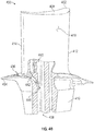
FIG. 4A is a partial cutaway, schematic illustration of an airfoil formed in accordance with an embodiment of the present disclosure, after casting, but prior to a machining process; -
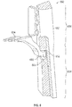
FIG. 4B is a schematic illustration of the airfoil ofFIG. 4A after a machining process in accordance with an embodiment of the present disclosure; -
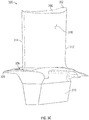
FIG. 5A is an isometric illustration of an airfoil in accordance with an embodiment of the present disclosure; -
FIG. 5B is a sectional of the airfoil ofFIG. 5A as viewed at the line B-B; -
FIG. 5C is a sectional of the airfoil ofFIG. 5A as viewed at the line C-C; -
FIG. 5D is a sectional of the airfoil ofFIG. 5A as viewed at the line D-D; -
FIG. 5E is a sectional of the airfoil ofFIG. 5A as viewed at the line E-E prior to a machining process of the present disclosure; -
FIG. 5F is a sectional of the airfoil ofFIG. 5A as viewed at the line E-E after a machining process of the present disclosure; -
FIG. 6 is a schematic illustration of a core assembly in accordance with an embodiment of the present disclosure; -
FIG. 7 is a flow process for manufacturing an airfoil in accordance with an embodiment of the present disclosure; -
FIG. 8 is a schematic illustration of a core assembly in accordance with an embodiment of the present disclosure; -
FIG. 9A is a partial-sectional view of an airfoil in accordance with an embodiment of the present disclosure prior to a machining process; and -
FIG. 9B is a partial-sectional view of the airfoil ofFIG. 9A after a machining process in accordance with an embodiment of the present disclosure. - Detailed descriptions of one or more embodiments of the disclosed apparatus and/or methods are presented herein by way of exemplification and not limitation with reference to the Figures.
-
FIG. 1 schematically illustrates agas turbine engine 20. Thegas turbine engine 20 is disclosed herein as a two-spool turbofan that generally incorporates afan section 22, acompressor section 24, acombustor section 26 and aturbine section 28. Thefan section 22 drives air along a bypass flow path B in a bypass duct, while thecompressor section 24 drives air along a core flow path C for compression and communication into thecombustor section 26 then expansion through theturbine section 28. Although depicted as a two-spool turbofan gas turbine engine in the disclosed non-limiting embodiment, it should be understood that the concepts described herein are not limited to use with two-spool turbofans as the teachings may be applied to other types of turbine engines. - The
exemplary engine 20 generally includes alow speed spool 30 and ahigh speed spool 32 mounted for rotation about an engine central longitudinal axis A relative to an enginestatic structure 36 viaseveral bearing systems 38. It should be understood that various bearingsystems 38 at various locations may alternatively or additionally be provided, and the location of bearingsystems 38 may be varied as appropriate to the application. - The
low speed spool 30 generally includes aninner shaft 40 that interconnects afan 42, alow pressure compressor 44 and alow pressure turbine 46. Theinner shaft 40 can be connected to thefan 42 through a speed change mechanism, which in exemplarygas turbine engine 20 is illustrated as agear system 48 to drive thefan 42 at a lower speed than thelow speed spool 30. Thehigh speed spool 32 includes anouter shaft 50 that interconnects ahigh pressure compressor 52 andhigh pressure turbine 54. Acombustor 56 is arranged inexemplary gas turbine 20 between thehigh pressure compressor 52 and thehigh pressure turbine 54. An enginestatic structure 36 is arranged generally between thehigh pressure turbine 54 and thelow pressure turbine 46. The enginestatic structure 36 furthersupports bearing systems 38 in theturbine section 28. Theinner shaft 40 and theouter shaft 50 are concentric and rotate via bearingsystems 38 about the engine central longitudinal axis A which is collinear with their longitudinal axes. - The core airflow is compressed by the
low pressure compressor 44 then thehigh pressure compressor 52, mixed and burned with fuel in thecombustor 56, then expanded over thehigh pressure turbine 54 andlow pressure turbine 46. Theturbines low speed spool 30 andhigh speed spool 32 in response to the expansion. It will be appreciated that each of the positions of thefan section 22,compressor section 24,combustor section 26,turbine section 28, and fandrive gear system 48 may be varied. For example,gear system 48 may be located aft ofcombustor section 26 or even aft ofturbine section 28, andfan section 22 may be positioned forward or aft of the location ofgear system 48. - The
engine 20 in one example is a high-bypass geared aircraft engine. In a further example, theengine 20 bypass ratio is greater than about six (6), with an example embodiment being greater than about ten (10), thegear system 48 is an epicyclic gear train, such as a planetary gear system or other gear system, with a gear reduction ratio of greater than about 2.3 and thelow pressure turbine 46 has a pressure ratio that is greater than about five (5:1). In one disclosed embodiment, theengine 20 bypass ratio is greater than about ten (10:1), the fan diameter is significantly larger than that of thelow pressure compressor 44, and thelow pressure turbine 46 has a pressure ratio that is greater than about five (5:1).Low pressure turbine 46 pressure ratio is pressure measured prior to inlet oflow pressure turbine 46 as related to the pressure at the outlet of thelow pressure turbine 46 prior to an exhaust nozzle. Thegear system 48 may be an epicyclic gear train, such as a planetary gear system or other gear system, with a gear reduction ratio of greater than about 2.3:1. It should be understood, however, that the above parameters are only exemplary of one embodiment of a geared architecture engine and that the present disclosure is applicable to other gas turbine engines including direct drive turbofans. - A significant amount of thrust is provided by the bypass flow B due to the high bypass ratio. The
fan section 22 of theengine 20 is designed for a particular flight condition--typically cruise at about 0.8 Mach and about 35,000 feet (10,668 meters). The flight condition of 0.8 Mach and 35,000 ft (10,668 meters), with the engine at its best fuel consumption--also known as "bucket cruise Thrust Specific Fuel Consumption ('TSFC')"--is the industry standard parameter of lbm of fuel being burned divided by lbf of thrust the engine produces at that minimum point. "Low fan pressure ratio" is the pressure ratio across the fan blade alone, without a Fan Exit Guide Vane ("FEGV") system. The low fan pressure ratio as disclosed herein according to one non-limiting embodiment is less than about 1.45. "Low corrected fan tip speed" is the actual fan tip speed in ft/sec divided by an industry standard temperature correction of [(Tram °R)/(514.7 °R)]0.5. The "Low corrected fan tip speed" as disclosed herein according to one non-limiting embodiment is less than about 1150 ft/second (350.5 m/sec). - Although the
gas turbine engine 20 is depicted as a turbofan, it should be understood that the concepts described herein are not limited to use with the described configuration, as the teachings may be applied to other types of engines such as, but not limited to, turbojets, turboshafts, and turbofans wherein an intermediate spool includes an intermediate pressure compressor ("IPC") between a low pressure compressor ("LPC") and a high pressure compressor ("HPC"), and an intermediate pressure turbine ("IPT") between the high pressure turbine ("HPT") and the low pressure turbine ("LPT"). -
FIG. 2 is a schematic view of a turbine section that may employ various embodiments disclosed herein.Turbine 200 includes a plurality of airfoils, including, for example, one ormore blades 201 and vanes 202 (collectively "airfoils airfoils inner diameter 206 to anouter diameter 208, or vice-versa. The airfoil cavities may be separated by partitions or internal walls or structures within theairfoils inner diameter 206 or theouter diameter 208 of theairfoils airfoils airfoils respective airfoils blades 201 and thevanes 202, as shown, are airfoils that extend fromplatforms 210 located proximal to the inner diameter thereof. Located below theplatforms 210 may be airflow ports and/or bleed orifices that enable air to bleed from the internal cavities of theairfoils platform 210. Such roots may enable connection to a turbine disc, as will be appreciated by those of skill in the art. - The
turbine 200 is housed within acase 212, which may have multiple parts (e.g., turbine case, diffuser case, etc.). In various locations, components, such as seals, may be positioned between theairfoils case 212. For example, as shown inFIG. 2 , blade outer air seals 214 (hereafter "BOAS") are located radially outward from theblades 201. As will be appreciated by those of skill in the art, theBOAS 214 can include BOAS supports that are configured to fixedly connect or attach theBOAS 214 to the case 212 (e.g., the BOAS supports can be located between the BOAS and the case). As shown inFIG. 2 , thecase 212 includes a plurality ofhooks 218 that engage with thehooks 216 to secure theBOAS 214 between thecase 212 and a tip of theblade 201. - As shown and labeled in
FIG. 2 , a radial direction R is upward on the page (e.g., radial with respect to an engine axis) and an axial direction A is to the right on the page (e.g., along an engine axis). Thus, radial cooling flows will travel up or down on the page and axial flows will travel left-to-right (or vice versa). A circumferential direction C is a direction into and out of the page about the engine axis. - Typically, airfoil cooling includes impingement cavities for cooling various hot surfaces of the airfoils. For example, it may be desirable to position a leading edge impingement cavity immediately adjacent to the external leading edge of the airfoil (e.g., left side edge of the
airfoils 201, 202). The leading edge impingement cavity is typically supplied cooling airflow from impingement apertures which serve as conduits for cooling air that originates within the leading edge cooling cavities of the airfoil. Once in the leading edge impingement cavity, the cooling air flow is expelled through an array of shower head holes, thus providing increased convective cooling and a protective film to mitigate the locally high external heat flux along the leading edge airfoil surface. - Turning now to
FIGS. 3A-3C , schematic illustrations of anairfoil 300 are shown.FIG. 3A is an isometric illustration of a leading edge of theairfoil 300.FIG. 3B is a cross-sectional illustration of theairfoil 300 as viewed along the line B-B shown inFIG. 3A .FIG. 3C is an isometric illustration of a trailing edge of theairfoil 300. Theairfoil 300, as shown, is arranged as a blade having anairfoil body 302 that extends from aplatform 304 from aroot 306 to atip 308. Theplatform 304 may be integrally formed with or attached to anattachment element 310, theattachment element 310 being configured to attach to or engage with a rotor disc for installation of theairfoil body 302 thereto. Theairfoil body 302 extends in an axial direction A from aleading edge 312 to a trailingedge 314, and in a radial direction R from theroot 306 to thetip 308. In the circumferential direction C, theairfoil body 302 extends between apressure side 316 and asuction side 318. - As shown in
FIG. 3B , illustrating a cross-sectional view of theairfoil 300, as viewed along the line B-B shown inFIG. 3A , theairfoil body 302 defines or includes a plurality of internal cavities to enable cooling of theairfoil 300. For example, as shown, theairfoil 300 includes a plurality of forward and side coolingcavities leading edge cavity 320 is located along theleading edge 312 of theairfoil body 302,pressure side cavities 322 are arranged along thepressure side 316 and proximate theleading edge 312, and asuction side cavity 324 is arranged along thesuction side 318 and proximate theleading edge 312. In the relative middle of theairfoil body 302, theairfoil 300 includes variousmain body cavities edge 314, a trailingedge slot 334. Some of the main body cavities may form a serpentine flow path through theairfoil 300, (e.g.,cavities cavities cavity 326 may be referred to as a leading edge feed cavity. Although shown with a specific internal cooling cavity arrangement, airfoils in accordance with the present disclosure may include additional and/or alternative cavities, flow paths, channels, etc. as will be appreciated by those of skill in the art, including, but not limited to, tip cavities, serpentine cavities, trailing edge cavities, etc. - Some or all of the
internal cavities attachment element 310 and through theplatform 304. Cooling is also provided to theplatform 304, and particularly to the hot gaspath surfaces of theplatform 304, as will be appreciated by those of skill in the art. For example, as shown inFIG. 3C , theplatform 304 may include one or more platform cooling holes 336. The platform cooling holes 336 may be arranged as film cooling holes that expel cool air from within theplatform 304 out onto a hot gaspath surface. Further, in some embodiments, as will be appreciated by those of skill in the art, theplatform 304 may include one or more platform cooling holes that are arranged on side facing surfaces, e.g., between adjacent blades. The platform cooling holes 336 may be fed from a cool air source within or below theplatform 304 and/or theattachment element 310. - Providing a common cooling source for both the airfoil cavities and the platform may be difficult due to limitations of manufacturing processes. For example, a core for forming a platform cooling circuit may have different thermal expansion characteristics than a core for forming a main body of an airfoil, and thus during the manufacturing process, consistent and/or efficient means for forming a complete airfoil and platform may be difficult to achieve. Accordingly, embodiments provided herein are directed to core assemblies and airfoils that enable improved manufacturing techniques and improved cooling schemes for airfoils and platforms of airfoils.
- Turning now to
FIGS. 4A-4B , schematic illustrations of anairfoil 400 in accordance with an embodiment of the present disclosure are shown.FIG. 4A illustrates a formedairfoil 400 after casting, but prior to a machining process in accordance with the present disclosure, andFIG. 4B illustrates theairfoil 400 after the machining process. - The
airfoil 400 is substantially similar to theairfoil 300 shown and described with respect toFIG. 3 . As such, theairfoil 400 is arranged as a blade having anairfoil body 402 that extends from aplatform 404 from aroot 406 to atip 408. Theplatform 404 may be integrally formed with or attached to anattachment element 410, theattachment element 410 being configured to attach to or engage with a rotor disc for installation of theairfoil body 402 thereto. Theairfoil body 402 extends in an axial direction from aleading edge 412 to a trailingedge 414, and in a radial direction from theroot 406 to thetip 408. In a circumferential direction, theairfoil body 402 extends between a pressure side (not shown in this view) and asuction side 418. Theplatform 404 includes one or more platform cooling holes 436, as described above. -
FIGS. 4A-4B are partial cut-away views, illustrating an internal structure of a portion of theairfoil body 402, theplatform 404, and theattachment element 410. As shown, theattachment element 410 includes at least one mainbody feed cavity 438 that is arranged to supply cooling air into theairfoil body 402, e.g., into one or more main body cavities 440. For example, themain body cavities 440 may include, but are not limited to, one or more of theinternal cavities FIG. 3B . Also shown is aplatform cooling circuit 442 that can supply cooling air into and through theplatform 404 and out through the one or more platform cooling holes 436. - In the interim manufacturing step shown in
FIG. 4A , theairfoil 400 is formed with a platformcore extension element 444. The platformcore extension element 444 is formed during the manufacturing process of the present disclosure to enable and/or ensure proper mating and formation of cores. - As shown in
FIG. 4B , a machining process may be used to remove the platformcore extension element 444. With the platformcore extension element 444 removed, the mainbody feed cavity 438 can now supply cooling air to both themain body cavities 440 and theplatform cooling circuit 442. That is, with the removal of the platformcore extension element 444, a platformcooling circuit bypass 446 is formed along the mainbody feed cavity 438 to bleed or extract a portion of the cooling air and divert it into and through theplatform cooling circuit 442. The cooling air will then be expelled out through the one or more platform cooling holes 436. - Turning now to
FIGS. 5A-5F , schematic illustrations of anairfoil 500 in accordance with an embodiment of the present disclosure are shown.FIG. 5A is an isometric illustration of theairfoil 500 as viewed toward the trailing edge thereof,FIG. 5B is a sectional of theairfoil 500 at the line B-B,FIG. 5C is a sectional of theairfoil 500 at the line C-C,FIG. 5D is a sectional of theairfoil 500 at the line D-D,FIG. 5E is a sectional of theairfoil 500 at the line E-E, andFIG. 5F is a sectional of theairfoil 500 at the line E-E after a machining process of the present disclosure. - The
airfoil 500 is substantially similar to the airfoils shown and described above. Theairfoil 500 is arranged as a blade having anairfoil body 502 that extends from aplatform 504 extending between a root and a tip. Theplatform 504 may be integrally formed with or attached to anattachment element 510, theattachment element 510 being configured to attach to or engage with a rotor disc for installation of theairfoil body 502 thereto. Theairfoil body 502 extends in an axial direction between a leading edge and a trailing edge, and in a radial direction from the root to the tip. In a circumferential direction, the airfoil body extends between a pressure side and a suction side. Theplatform 504 includes one or more platform cooling holes 536, as described above, that fluidly connect to a platform cooling circuit. The airfoil contains one or more internal main body cavities therein. - With reference to
FIG. 5B , the sectional illustrates theplatform 504 with a plurality ofmain body cavities 540 and aplatform cooling circuit 542 formed therein. Theplatform cooling circuit 542 includes one or more platform cooling holes 536, as described above and as will be appreciated by those of skill in the art. As shown inFIG. 5B , theplatform cooling circuit 542 and themain body cavities 540 are separated. As theplatform cooling circuit 542 and themain body cavities 540 extend radially inward through theattachment element 510, the geometries thereof change, as shown inFIGS. 5C-5D . - Referring now to
FIG. 5E , mainbody feed cavities 538 are shown which fluidly connected to the main body cavities 540. The mainbody feed cavities 538 may continue radially inward to a source of cooling air when installed within a turbine section of a gas turbine engine.FIG. 5E illustrates theattachment element 510 pre-machining, but post-casting. That is, a platformcore extension element 444 separates theplatform cooling circuit 542 from one of the main body feed cavities 538. - As shown in
FIG. 5F , which illustrates the same sectional asFIG. 5E , the platformcore extension element 544 has been removed, such as by machining, and theplatform cooling circuit 542 is now fluidly connected to one of the mainbody feed cavities 538 through a platformcooling circuit bypass 546. Advantageously, in accordance with embodiments of the present disclosure, a single cooling source can be used to supply cooling air to both themain body cavities 540 of an airfoil and also to theplatform cooling circuit 542. - Turning now to
FIG. 6 , a schematic illustration of acore assembly 650 in accordance with an embodiment of the present disclosure is shown. Thecore assembly 650 may be used to form an airfoil in accordance with the present disclosure, such as the airfoils shown and described above. - The core assembly includes a
main body core 652 and aplatform circuit core 654. Themain body core 652 includes an airfoilcavity core portion 656 and a feedcavity core portion 658. The airfoilcavity core portion 656 can include one or more cores that are arranged and positioned to enable the formation of one or more cavities within a formed airfoil body. The feedcavity core portion 658 is arranged to aid in the formation of a platform and attachment element and form feed cavities therein and/or therethrough. Theplatform circuit core 654 is arranged to form a platform cooling circuit within a platform of the formed airfoil, and can include various features as will be appreciated by those of skill in the art (e.g., features to form one or more platform cooling holes). - As shown, the
platform circuit core 654 includes aplatform core extension 660. Theplatform core extension 660 is arranged to fit within anotch 662 of the feedcavity core portion 658 of themain body core 652. That is, the feedcavity core portion 658 of themain body core 652 is formed with thenotch 662 therein, with thenotch 662 positioned to form platform cooling circuit bypass in a formed airfoil. - The dimensions of the
platform core extension 660 and thenotch 662 are selected to allow for agap 664 to be present when theplatform core extension 660 is inserted into thenotch 662 when casting an airfoil. Thegap 664 allows for different thermal expansion coefficients of theplatform circuit core 654 and themain body core 652 during the casting process. Thus, failure and/or damage may be avoided during the formation of the airfoil at the location of the joining of theplatform circuit core 654 and themain body core 652. Thegap 664 allows for some amount of casting material to enter therein, thus forming a platform core extension element (e.g., as shown inFIGS. 4A and5E ) which may be subsequently removed by machining or other process, as will be appreciated by those of skill in the art. In accordance with an example embodiment, the gap is between about 0.015 inches (0.38 mm) and about 0.050 inches (1.27 mm). - Although the
platform core extension 660 inFIG. 6 is shown with a substantially squared cross-section, such geometry is not to be limiting. For example, a cylindrical or conical shape may be employed without departing from the scope of the present disclosure. The geometric shape of the platform core extension may be arranged to achieve specific design considerations or may be selected for other reasons. For example, a conical shape may result in a more smooth transition in the formed cooling cavities (e.g., decreased inlet losses). Other geometries may provide for improved structure, such as ovals, smooth, filleted shapes, etc. Accordingly, the geometry of the connection and engagement at the notch is not to be limiting. - Further, the shape of the formed opening, by removal of the platform core extension element, may take any desired geometric shapes, and may be defined, in part, by the shape of the notch and the extension that engages therewith. Moreover, the machining process may be selected or performed to achieve a desired transition at the junction between the main body feed cavity and the platform cooling circuit. Thus, the illustrative embodiments shown and described herein are merely for example and are not to be limiting.
- Turning now to
FIG. 7 , aflow process 700 for forming an airfoil in accordance with an embodiment of the present disclosure is shown. The flow process may be used to form an airfoil having a platform cooling circuit that is fluidly connected to a main body feed cavity, as shown and described above. - At
block 702, a main body core is formed, with the main body core being configured to enable casting of an airfoil body having internal cavities and main body feed cavities formed within and/or through a platform and an attachment element of the airfoil. At least one feed cavity core portion of the main body core is formed with a notch, such as shown and described above. - At
block 704, a platform circuit core is formed for forming a platform cooling circuit within the platform of the formed airfoil. The platform circuit core is formed with a platform core extension to enable engagement and assembly with the main body core. - At
block 706, the platform circuit core is assembled to the main body core with the platform core extension inserted in or engaged with the notch of the notch of the main body core. When assembled, a gap is formed between the platform core extension and the surfaces of the main body core defining the notch. The gap is provided to allow for changes in shape/size of the main body core and/or the platform core extension due to thermal influences during a casting process. - At
block 708, an airfoil is cast using the assembled platform circuit core and main body core. During the casting process, a platform core extension element is formed within the gap between the platform core extension and the surfaces of the main body core defining the notch. - At
block 710, the platform core extension element is removed to form a platform cooling circuit bypass. That is, the platform core extension element is removed to fluidly connect a main body feed cavity to a formed platform cooling circuit. - Turning now to
FIG. 8 , a schematic illustration of acore assembly 870 in accordance with an embodiment of the present disclosure is shown. Thecore assembly 870 may be used to form airfoils having features as shown and described above. In this arrangement, thecore assembly 870 includes aplatform circuit core 871 and amain body core 872. Theplatform circuit core 871 includes aplatform core extension 873 defining anotch 874 to receive aportion 875 of themain body core 872 therein. The end result of such configuration is an airfoil similar to that shown and described above. A gap may be present between thenotch 874 and theportion 875 of themain body core 872, as described above. As shown, theportion 875 of themain body core 872 may be a reduced thickness portion of themain body core 872 such that the resulting joinedmain body core 872 andplatform circuit core 871 do not occupy additional space or volume as compared to the embodiments shown and described above. - It is noted that
FIG. 8 illustrates an alternative configuration to the prior described embodiments. Those of skill in the art will appreciate that further arrangements may be possible without departing from the scope of the present disclosure. For example, in some embodiments, the platform circuit core may define a notch at an end thereof, with a core extension extending from a side of the main body core (i.e., the opposite of the arrangement shown inFIG. 6 ). - Turning now to
FIGS. 9A-9B , schematic illustrations of anairfoil 980 in accordance with an embodiment of the present disclosure are shown.FIG. 9A is a partial-sectional view of theairfoil 980, prior to a machining process.FIG. 9B is a partial-sectional view of theairfoil 980, after a machining process. Theairfoil 980 may be formed using a core assembly similar to that shown inFIG. 8 . The illustration inFIGS. 9A-9B may be of a portion of an attachment element of theairfoil 980, similar to that shown and described above. - As shown, a main
body feed cavity 981 is formed within theairfoil 980 and my fluidly connect to one or more main body cavities of theairfoil 980. The mainbody feed cavity 981 may extend, downward on the page, to a source of cooling air when installed within a turbine section of a gas turbine engine.FIG. 9A illustrates theairfoil 980 pre-machining, but post-casting. In this illustration, a platformcore extension element 982 separates aplatform cooling circuit 983 from the mainbody feed cavity 981. -
FIG. 9B illustrates the same sectional asFIG. 9A , but the platformcore extension element 982 has been removed, such as by machining, and theplatform cooling circuit 983 is now fluidly connected to the mainbody feed cavity 981 through a platformcooling circuit bypass 984. Advantageously, in accordance with embodiments of the present disclosure, a single cooling source can be used to supply cooling air to both the main body cavities of an airfoil and also to theplatform cooling circuit 983. - As used herein, the term "about" is intended to include the degree of error associated with measurement of the particular quantity based upon the equipment available at the time of filing the application. For example, "about" may include a range of ± 8%, or 5%, or 2% of a given value or other percentage change as will be appreciated by those of skill in the art for the particular measurement and/or dimensions referred to herein.
- The terminology used herein is for the purpose of describing particular embodiments only and is not intended to be limiting of the present disclosure. As used herein, the singular forms "a," "an," and "the" are intended to include the plural forms as well, unless the context clearly indicates otherwise. It will be further understood that the terms "comprises" and/or "comprising," when used in this specification, specify the presence of stated features, integers, steps, operations, elements, and/or components, but do not preclude the presence or addition of one or more other features, integers, steps, operations, element components, and/or groups thereof. It should be appreciated that relative positional terms such as "forward," "aft," "upper," "lower," "above," "below," "radial," "axial," "circumferential," and the like are with reference to normal operational attitude and should not be considered otherwise limiting.
- While the present disclosure has been described with reference to an illustrative embodiment or embodiments, it will be understood by those skilled in the art that various changes may be made and equivalents may be substituted for elements thereof without departing from the scope of the present disclosure. In addition, many modifications may be made to adapt a particular situation or material to the teachings of the present disclosure without departing from the essential scope thereof. Therefore, it is intended that the present disclosure not be limited to the particular embodiment disclosed as the best mode contemplated for carrying out this present disclosure, but that the present disclosure will include all embodiments falling within the scope of the claims.
Claims (15)
- A method (700) for manufacturing an airfoil (400; 500; 980) of a gas turbine engine (20), the method comprising:forming (702) a main body core (652; 872), the main body core including a feed cavity core portion (658), the main body core configured to form at least a part of an airfoil including an airfoil body (402; 502), a platform (404; 504), and an attachment element (410; 510);forming (704) a platform circuit core (654; 871) having a platform core extension (660; 873), wherein the platform circuit core is configured to form a cooling circuit (442; 542; 983) in the platform, wherein at least one of the feed cavity core portion and the platform core extension comprises a notch (662; 874);assembling (706) the platform circuit core to the main body core such that the platform core extension engages with the feed cavity core portion at the notch;casting (708) the airfoil using the assembled platform circuit core and main body core; andremoving (710) a platform core extension element (444; 544; 982) that is formed at the location of the notch.
- The method of claim 1, wherein a gap (664) is formed between the platform core extension (660; 873) and the feed cavity core portion (658) when engaged.
- The method of claim 2, wherein the platform core extension element (444; 544; 982) is formed by material of the casting located within the gap (664).
- The method of claim 2 or claim 3, wherein the gap (664) is between 0.015 inches (0.38 mm) and 0.050 inches (1.27 mm).
- The method of any preceding claim, wherein the removal of the platform core extension element (444; 544; 982) comprises a machining process.
- The method of any preceding claim, wherein removal of the platform core extension element (444; 544; 982) fluidly connects a formed main body feed cavity (438; 538; 981) and a formed platform cooling circuit (442; 542; 983).
- The method of any preceding claim, wherein the notch (662) is formed in the feed cavity core portion (658) and the platform core extension (660) engages within the notch of the feed cavity core portion.
- The method of any of claims 1 to 6, wherein the notch (874) is formed within the platform core extension (873) and the feed cavity core portion engages within the notch of the platform core extension; optionally wherein the feed cavity core portion comprises a reduced width portion (875) that engages with the notch of the platform core extension.
- A core assembly (650; 870) for forming an airfoil (400; 500; 980) of a gas turbine engine, the core assembly comprising:a main body core (652; 872), the main body core including at least one feed cavity core portion (658), the main body core configured to form an airfoil including an airfoil body (402; 502), a platform (404; 504), and an attachment element (410; 510); anda platform circuit core (654; 871) having a platform core extension (660; 873), wherein at least one of the feed cavity core portion and the platform core extension comprises a notch (662; 874);wherein the platform core extension is engageable with the feed cavity core portion at the notch and a gap (664) is formed between the platform circuit core extension and a surface of the feed cavity core portion at the notch.
- The core assembly of claim 9, wherein the gap (664) is between 0.015 inches (0.38 mm) and 0.050 inches (1.27 mm).
- The core assembly of claim 9 or claim 10, wherein the notch (662) is formed in the feed cavity core portion (658) and the platform core extension (660) engages within the notch of the feed cavity core portion.
- The core assembly of claim 9 or claim 10, wherein the notch (874) is formed within the platform core extension (873) and the feed cavity core portion engages within the notch of the platform core extension; optionally wherein the feed cavity core portion comprises a reduced width portion (875) that engages with the notch of the platform core extension.
- An airfoil (400; 500; 980) of a gas turbine engine (20) comprising:an airfoil body (402; 502) extending from a platform (404; 504) and an attachment element (410; 510), wherein at least one of the platform and the attachment element include at least one feed cavity (438; 538; 981); anda platform cooling circuit (442; 542; 983) formed within the platform, wherein the platform cooling circuit is fluidly connected to the at least one feed cavity at a platform cooling circuit bypass (446; 546; 984).
- The airfoil of claim 13, wherein the platform cooling circuit (442; 542; 983) comprises at least one platform cooling hole (336; 536) formed in the platform such that cooling air flows from the at least one feed cavity (438; 538; 981), through the platform cooling circuit bypass (446; 546; 984), through the platform cooling circuit, and out through the at least one platform cooling hole.
- The airfoil of claim 13 or claim 14, wherein the airfoil body (402; 502) defines at least one main body cavity (440; 540), wherein the main body cavity is fluidly connected to the at least one feed cavity (438; 538; 981).
Applications Claiming Priority (1)
| Application Number | Priority Date | Filing Date | Title |
|---|---|---|---|
| US15/954,857 US10801333B2 (en) | 2018-04-17 | 2018-04-17 | Airfoils, cores, and methods of manufacture for forming airfoils having fluidly connected platform cooling circuits |
Publications (2)
| Publication Number | Publication Date |
|---|---|
| EP3564485A1 true EP3564485A1 (en) | 2019-11-06 |
| EP3564485B1 EP3564485B1 (en) | 2021-06-23 |
Family
ID=66217834
Family Applications (1)
| Application Number | Title | Priority Date | Filing Date |
|---|---|---|---|
| EP19169644.2A Active EP3564485B1 (en) | 2018-04-17 | 2019-04-16 | Airfoils, cores, and methods of manufacture for forming airfoils having fluidly connected platform cooling circuits |
Country Status (2)
| Country | Link |
|---|---|
| US (1) | US10801333B2 (en) |
| EP (1) | EP3564485B1 (en) |
Families Citing this family (2)
| Publication number | Priority date | Publication date | Assignee | Title |
|---|---|---|---|---|
| US11021966B2 (en) * | 2019-04-24 | 2021-06-01 | Raytheon Technologies Corporation | Vane core assemblies and methods |
| FR3114838B1 (en) * | 2020-10-01 | 2023-06-16 | Safran Aircraft Engines | Turbine blade for an aircraft turbomachine, comprising a platform provided with a primary flow rejection channel towards a purge cavity |
Citations (5)
| Publication number | Priority date | Publication date | Assignee | Title |
|---|---|---|---|---|
| EP1216785A2 (en) * | 2000-12-22 | 2002-06-26 | ALSTOM Power N.V. | Method for the rapid manufacturing of hollow components of turbomachines for the development of the fabrication |
| EP1621727A1 (en) * | 2004-07-30 | 2006-02-01 | General Electric Company | Turbine rotor blade and gas turbine engine rotor assembly comprising such blades |
| US20110142684A1 (en) * | 2009-12-15 | 2011-06-16 | Campbell Christian X | Turbine Engine Airfoil and Platform Assembly |
| WO2014150301A1 (en) * | 2013-03-15 | 2014-09-25 | United Technologies Corporation | Article with sections having different microstructures and method therefor |
| WO2015057310A2 (en) * | 2013-09-17 | 2015-04-23 | United Technologies Corporation | Platform cooling core for a gas turbine engine rotor blade |
Family Cites Families (9)
| Publication number | Priority date | Publication date | Assignee | Title |
|---|---|---|---|---|
| US5634767A (en) | 1996-03-29 | 1997-06-03 | General Electric Company | Turbine frame having spindle mounted liner |
| US8517666B2 (en) | 2005-09-12 | 2013-08-27 | United Technologies Corporation | Turbine cooling air sealing |
| US7303375B2 (en) | 2005-11-23 | 2007-12-04 | United Technologies Corporation | Refractory metal core cooling technologies for curved leading edge slots |
| US20130025123A1 (en) | 2011-07-29 | 2013-01-31 | United Technologies Corporation | Working a vane assembly for a gas turbine engine |
| US9702252B2 (en) | 2012-12-19 | 2017-07-11 | Honeywell International Inc. | Turbine nozzles with slip joints and methods for the production thereof |
| US9957813B2 (en) | 2013-02-19 | 2018-05-01 | United Technologies Corporation | Gas turbine engine airfoil platform cooling passage and core |
| US9611748B2 (en) | 2013-12-06 | 2017-04-04 | Honeywell International Inc. | Stationary airfoils configured to form improved slip joints in bi-cast turbine engine components and the turbine engine components including the same |
| US10041374B2 (en) * | 2014-04-04 | 2018-08-07 | United Technologies Corporation | Gas turbine engine component with platform cooling circuit |
| US9885245B2 (en) | 2014-05-20 | 2018-02-06 | Honeywell International Inc. | Turbine nozzles and cooling systems for cooling slip joints therein |
-
2018
- 2018-04-17 US US15/954,857 patent/US10801333B2/en active Active
-
2019
- 2019-04-16 EP EP19169644.2A patent/EP3564485B1/en active Active
Patent Citations (5)
| Publication number | Priority date | Publication date | Assignee | Title |
|---|---|---|---|---|
| EP1216785A2 (en) * | 2000-12-22 | 2002-06-26 | ALSTOM Power N.V. | Method for the rapid manufacturing of hollow components of turbomachines for the development of the fabrication |
| EP1621727A1 (en) * | 2004-07-30 | 2006-02-01 | General Electric Company | Turbine rotor blade and gas turbine engine rotor assembly comprising such blades |
| US20110142684A1 (en) * | 2009-12-15 | 2011-06-16 | Campbell Christian X | Turbine Engine Airfoil and Platform Assembly |
| WO2014150301A1 (en) * | 2013-03-15 | 2014-09-25 | United Technologies Corporation | Article with sections having different microstructures and method therefor |
| WO2015057310A2 (en) * | 2013-09-17 | 2015-04-23 | United Technologies Corporation | Platform cooling core for a gas turbine engine rotor blade |
Also Published As
| Publication number | Publication date |
|---|---|
| US10801333B2 (en) | 2020-10-13 |
| US20190316471A1 (en) | 2019-10-17 |
| EP3564485B1 (en) | 2021-06-23 |
Similar Documents
| Publication | Publication Date | Title |
|---|---|---|
| EP3757352B1 (en) | Method for forming an airfoil with internal cavities | |
| EP3453832B1 (en) | Hot section engine components having segment gap discharge holes | |
| EP3054094B1 (en) | Gas turbine engine turbine vane baffle and serpentine cooling passage | |
| EP3444435B1 (en) | Expansion seal for airfoil for gas turbine engine | |
| EP3564485B1 (en) | Airfoils, cores, and methods of manufacture for forming airfoils having fluidly connected platform cooling circuits | |
| EP3757351B1 (en) | Method for manufacturing an airfoil | |
| EP3567219B1 (en) | Airfoil for a gas turbine engine | |
| EP3567218B1 (en) | Airfoil having improved leading edge cooling scheme and damage resistance | |
| EP3477054A2 (en) | Airfoil having impingement leading edge | |
| US11168571B2 (en) | Airfoil having dead-end tip flag cavity | |
| EP3663517B1 (en) | Component for a gas turbine engine and corresponding gas turbine engine | |
| EP3564486B1 (en) | Airfoil having improved cooling scheme | |
| EP3708776A1 (en) | Gasturbine airfoils having tapered tip flag cavity and cores for forming the same | |
| EP3550110B1 (en) | Airfoil having leading edge cooling scheme with backstrike compensation | |
| EP3613949B1 (en) | Airfoil having improved throughflow cooling scheme and damage resistance | |
| EP4417790A1 (en) | Air foil with staggered cooling hole configuration | |
| EP3431711B1 (en) | Airfoil having serpentine core resupply flow control | |
| EP3382152B1 (en) | Blade tip cooling design |
Legal Events
| Date | Code | Title | Description |
|---|---|---|---|
| PUAI | Public reference made under article 153(3) epc to a published international application that has entered the european phase |
Free format text: ORIGINAL CODE: 0009012 |
|
| STAA | Information on the status of an ep patent application or granted ep patent |
Free format text: STATUS: THE APPLICATION HAS BEEN PUBLISHED |
|
| AK | Designated contracting states |
Kind code of ref document: A1 Designated state(s): AL AT BE BG CH CY CZ DE DK EE ES FI FR GB GR HR HU IE IS IT LI LT LU LV MC MK MT NL NO PL PT RO RS SE SI SK SM TR |
|
| AX | Request for extension of the european patent |
Extension state: BA ME |
|
| STAA | Information on the status of an ep patent application or granted ep patent |
Free format text: STATUS: REQUEST FOR EXAMINATION WAS MADE |
|
| 17P | Request for examination filed |
Effective date: 20200505 |
|
| RBV | Designated contracting states (corrected) |
Designated state(s): AL AT BE BG CH CY CZ DE DK EE ES FI FR GB GR HR HU IE IS IT LI LT LU LV MC MK MT NL NO PL PT RO RS SE SI SK SM TR |
|
| GRAP | Despatch of communication of intention to grant a patent |
Free format text: ORIGINAL CODE: EPIDOSNIGR1 |
|
| STAA | Information on the status of an ep patent application or granted ep patent |
Free format text: STATUS: GRANT OF PATENT IS INTENDED |
|
| INTG | Intention to grant announced |
Effective date: 20200713 |
|
| GRAJ | Information related to disapproval of communication of intention to grant by the applicant or resumption of examination proceedings by the epo deleted |
Free format text: ORIGINAL CODE: EPIDOSDIGR1 |
|
| STAA | Information on the status of an ep patent application or granted ep patent |
Free format text: STATUS: REQUEST FOR EXAMINATION WAS MADE |
|
| INTC | Intention to grant announced (deleted) | ||
| GRAP | Despatch of communication of intention to grant a patent |
Free format text: ORIGINAL CODE: EPIDOSNIGR1 |
|
| STAA | Information on the status of an ep patent application or granted ep patent |
Free format text: STATUS: GRANT OF PATENT IS INTENDED |
|
| INTG | Intention to grant announced |
Effective date: 20210115 |
|
| RAP1 | Party data changed (applicant data changed or rights of an application transferred) |
Owner name: RAYTHEON TECHNOLOGIES CORPORATION |
|
| GRAS | Grant fee paid |
Free format text: ORIGINAL CODE: EPIDOSNIGR3 |
|
| GRAA | (expected) grant |
Free format text: ORIGINAL CODE: 0009210 |
|
| STAA | Information on the status of an ep patent application or granted ep patent |
Free format text: STATUS: THE PATENT HAS BEEN GRANTED |
|
| AK | Designated contracting states |
Kind code of ref document: B1 Designated state(s): AL AT BE BG CH CY CZ DE DK EE ES FI FR GB GR HR HU IE IS IT LI LT LU LV MC MK MT NL NO PL PT RO RS SE SI SK SM TR |
|
| REG | Reference to a national code |
Ref country code: GB Ref legal event code: FG4D |
|
| REG | Reference to a national code |
Ref country code: CH Ref legal event code: EP |
|
| REG | Reference to a national code |
Ref country code: DE Ref legal event code: R096 Ref document number: 602019005486 Country of ref document: DE Ref country code: AT Ref legal event code: REF Ref document number: 1404484 Country of ref document: AT Kind code of ref document: T Effective date: 20210715 |
|
| REG | Reference to a national code |
Ref country code: IE Ref legal event code: FG4D |
|
| REG | Reference to a national code |
Ref country code: LT Ref legal event code: MG9D |
|
| PG25 | Lapsed in a contracting state [announced via postgrant information from national office to epo] |
Ref country code: HR Free format text: LAPSE BECAUSE OF FAILURE TO SUBMIT A TRANSLATION OF THE DESCRIPTION OR TO PAY THE FEE WITHIN THE PRESCRIBED TIME-LIMIT Effective date: 20210623 Ref country code: LT Free format text: LAPSE BECAUSE OF FAILURE TO SUBMIT A TRANSLATION OF THE DESCRIPTION OR TO PAY THE FEE WITHIN THE PRESCRIBED TIME-LIMIT Effective date: 20210623 Ref country code: FI Free format text: LAPSE BECAUSE OF FAILURE TO SUBMIT A TRANSLATION OF THE DESCRIPTION OR TO PAY THE FEE WITHIN THE PRESCRIBED TIME-LIMIT Effective date: 20210623 Ref country code: BG Free format text: LAPSE BECAUSE OF FAILURE TO SUBMIT A TRANSLATION OF THE DESCRIPTION OR TO PAY THE FEE WITHIN THE PRESCRIBED TIME-LIMIT Effective date: 20210923 |
|
| REG | Reference to a national code |
Ref country code: AT Ref legal event code: MK05 Ref document number: 1404484 Country of ref document: AT Kind code of ref document: T Effective date: 20210623 |
|
| PG25 | Lapsed in a contracting state [announced via postgrant information from national office to epo] |
Ref country code: GR Free format text: LAPSE BECAUSE OF FAILURE TO SUBMIT A TRANSLATION OF THE DESCRIPTION OR TO PAY THE FEE WITHIN THE PRESCRIBED TIME-LIMIT Effective date: 20210924 Ref country code: SE Free format text: LAPSE BECAUSE OF FAILURE TO SUBMIT A TRANSLATION OF THE DESCRIPTION OR TO PAY THE FEE WITHIN THE PRESCRIBED TIME-LIMIT Effective date: 20210623 Ref country code: RS Free format text: LAPSE BECAUSE OF FAILURE TO SUBMIT A TRANSLATION OF THE DESCRIPTION OR TO PAY THE FEE WITHIN THE PRESCRIBED TIME-LIMIT Effective date: 20210623 Ref country code: NO Free format text: LAPSE BECAUSE OF FAILURE TO SUBMIT A TRANSLATION OF THE DESCRIPTION OR TO PAY THE FEE WITHIN THE PRESCRIBED TIME-LIMIT Effective date: 20210923 Ref country code: LV Free format text: LAPSE BECAUSE OF FAILURE TO SUBMIT A TRANSLATION OF THE DESCRIPTION OR TO PAY THE FEE WITHIN THE PRESCRIBED TIME-LIMIT Effective date: 20210623 |
|
| REG | Reference to a national code |
Ref country code: NL Ref legal event code: MP Effective date: 20210623 |
|
| PG25 | Lapsed in a contracting state [announced via postgrant information from national office to epo] |
Ref country code: SM Free format text: LAPSE BECAUSE OF FAILURE TO SUBMIT A TRANSLATION OF THE DESCRIPTION OR TO PAY THE FEE WITHIN THE PRESCRIBED TIME-LIMIT Effective date: 20210623 Ref country code: RO Free format text: LAPSE BECAUSE OF FAILURE TO SUBMIT A TRANSLATION OF THE DESCRIPTION OR TO PAY THE FEE WITHIN THE PRESCRIBED TIME-LIMIT Effective date: 20210623 Ref country code: NL Free format text: LAPSE BECAUSE OF FAILURE TO SUBMIT A TRANSLATION OF THE DESCRIPTION OR TO PAY THE FEE WITHIN THE PRESCRIBED TIME-LIMIT Effective date: 20210623 Ref country code: PT Free format text: LAPSE BECAUSE OF FAILURE TO SUBMIT A TRANSLATION OF THE DESCRIPTION OR TO PAY THE FEE WITHIN THE PRESCRIBED TIME-LIMIT Effective date: 20211025 Ref country code: CZ Free format text: LAPSE BECAUSE OF FAILURE TO SUBMIT A TRANSLATION OF THE DESCRIPTION OR TO PAY THE FEE WITHIN THE PRESCRIBED TIME-LIMIT Effective date: 20210623 Ref country code: AT Free format text: LAPSE BECAUSE OF FAILURE TO SUBMIT A TRANSLATION OF THE DESCRIPTION OR TO PAY THE FEE WITHIN THE PRESCRIBED TIME-LIMIT Effective date: 20210623 Ref country code: SK Free format text: LAPSE BECAUSE OF FAILURE TO SUBMIT A TRANSLATION OF THE DESCRIPTION OR TO PAY THE FEE WITHIN THE PRESCRIBED TIME-LIMIT Effective date: 20210623 Ref country code: EE Free format text: LAPSE BECAUSE OF FAILURE TO SUBMIT A TRANSLATION OF THE DESCRIPTION OR TO PAY THE FEE WITHIN THE PRESCRIBED TIME-LIMIT Effective date: 20210623 Ref country code: ES Free format text: LAPSE BECAUSE OF FAILURE TO SUBMIT A TRANSLATION OF THE DESCRIPTION OR TO PAY THE FEE WITHIN THE PRESCRIBED TIME-LIMIT Effective date: 20210623 |
|
| PG25 | Lapsed in a contracting state [announced via postgrant information from national office to epo] |
Ref country code: PL Free format text: LAPSE BECAUSE OF FAILURE TO SUBMIT A TRANSLATION OF THE DESCRIPTION OR TO PAY THE FEE WITHIN THE PRESCRIBED TIME-LIMIT Effective date: 20210623 |
|
| REG | Reference to a national code |
Ref country code: DE Ref legal event code: R097 Ref document number: 602019005486 Country of ref document: DE |
|
| PG25 | Lapsed in a contracting state [announced via postgrant information from national office to epo] |
Ref country code: DK Free format text: LAPSE BECAUSE OF FAILURE TO SUBMIT A TRANSLATION OF THE DESCRIPTION OR TO PAY THE FEE WITHIN THE PRESCRIBED TIME-LIMIT Effective date: 20210623 |
|
| PLBE | No opposition filed within time limit |
Free format text: ORIGINAL CODE: 0009261 |
|
| STAA | Information on the status of an ep patent application or granted ep patent |
Free format text: STATUS: NO OPPOSITION FILED WITHIN TIME LIMIT |
|
| 26N | No opposition filed |
Effective date: 20220324 |
|
| PG25 | Lapsed in a contracting state [announced via postgrant information from national office to epo] |
Ref country code: AL Free format text: LAPSE BECAUSE OF FAILURE TO SUBMIT A TRANSLATION OF THE DESCRIPTION OR TO PAY THE FEE WITHIN THE PRESCRIBED TIME-LIMIT Effective date: 20210623 |
|
| PG25 | Lapsed in a contracting state [announced via postgrant information from national office to epo] |
Ref country code: IT Free format text: LAPSE BECAUSE OF FAILURE TO SUBMIT A TRANSLATION OF THE DESCRIPTION OR TO PAY THE FEE WITHIN THE PRESCRIBED TIME-LIMIT Effective date: 20210623 |
|
| REG | Reference to a national code |
Ref country code: CH Ref legal event code: PL |
|
| REG | Reference to a national code |
Ref country code: BE Ref legal event code: MM Effective date: 20220430 |
|
| PG25 | Lapsed in a contracting state [announced via postgrant information from national office to epo] |
Ref country code: MC Free format text: LAPSE BECAUSE OF FAILURE TO SUBMIT A TRANSLATION OF THE DESCRIPTION OR TO PAY THE FEE WITHIN THE PRESCRIBED TIME-LIMIT Effective date: 20210623 Ref country code: LU Free format text: LAPSE BECAUSE OF NON-PAYMENT OF DUE FEES Effective date: 20220416 Ref country code: LI Free format text: LAPSE BECAUSE OF NON-PAYMENT OF DUE FEES Effective date: 20220430 Ref country code: CH Free format text: LAPSE BECAUSE OF NON-PAYMENT OF DUE FEES Effective date: 20220430 |
|
| PG25 | Lapsed in a contracting state [announced via postgrant information from national office to epo] |
Ref country code: BE Free format text: LAPSE BECAUSE OF NON-PAYMENT OF DUE FEES Effective date: 20220430 |
|
| PG25 | Lapsed in a contracting state [announced via postgrant information from national office to epo] |
Ref country code: IE Free format text: LAPSE BECAUSE OF NON-PAYMENT OF DUE FEES Effective date: 20220416 |
|
| P01 | Opt-out of the competence of the unified patent court (upc) registered |
Effective date: 20230521 |
|
| PG25 | Lapsed in a contracting state [announced via postgrant information from national office to epo] |
Ref country code: HU Free format text: LAPSE BECAUSE OF FAILURE TO SUBMIT A TRANSLATION OF THE DESCRIPTION OR TO PAY THE FEE WITHIN THE PRESCRIBED TIME-LIMIT; INVALID AB INITIO Effective date: 20190416 |
|
| PG25 | Lapsed in a contracting state [announced via postgrant information from national office to epo] |
Ref country code: MK Free format text: LAPSE BECAUSE OF FAILURE TO SUBMIT A TRANSLATION OF THE DESCRIPTION OR TO PAY THE FEE WITHIN THE PRESCRIBED TIME-LIMIT Effective date: 20210623 Ref country code: CY Free format text: LAPSE BECAUSE OF FAILURE TO SUBMIT A TRANSLATION OF THE DESCRIPTION OR TO PAY THE FEE WITHIN THE PRESCRIBED TIME-LIMIT Effective date: 20210623 |
|
| PG25 | Lapsed in a contracting state [announced via postgrant information from national office to epo] |
Ref country code: TR Free format text: LAPSE BECAUSE OF FAILURE TO SUBMIT A TRANSLATION OF THE DESCRIPTION OR TO PAY THE FEE WITHIN THE PRESCRIBED TIME-LIMIT Effective date: 20210623 |
|
| PG25 | Lapsed in a contracting state [announced via postgrant information from national office to epo] |
Ref country code: MT Free format text: LAPSE BECAUSE OF FAILURE TO SUBMIT A TRANSLATION OF THE DESCRIPTION OR TO PAY THE FEE WITHIN THE PRESCRIBED TIME-LIMIT Effective date: 20210623 |
|
| PGFP | Annual fee paid to national office [announced via postgrant information from national office to epo] |
Ref country code: DE Payment date: 20250319 Year of fee payment: 7 |
|
| REG | Reference to a national code |
Ref country code: DE Ref legal event code: R081 Ref document number: 602019005486 Country of ref document: DE Owner name: RTX CORPORATION (N.D.GES.D. STAATES DELAWARE),, US Free format text: FORMER OWNER: RAYTHEON TECHNOLOGIES CORPORATION, FARMINGTON, CT, US |
|
| PGFP | Annual fee paid to national office [announced via postgrant information from national office to epo] |
Ref country code: GB Payment date: 20260319 Year of fee payment: 8 |
|
| PGFP | Annual fee paid to national office [announced via postgrant information from national office to epo] |
Ref country code: FR Payment date: 20260320 Year of fee payment: 8 |