EP3564470A1 - Holding device for holding a door leaf in an open configuration releasable through a further opening of the door leaf - Google Patents
Holding device for holding a door leaf in an open configuration releasable through a further opening of the door leaf Download PDFInfo
- Publication number
- EP3564470A1 EP3564470A1 EP18290040.7A EP18290040A EP3564470A1 EP 3564470 A1 EP3564470 A1 EP 3564470A1 EP 18290040 A EP18290040 A EP 18290040A EP 3564470 A1 EP3564470 A1 EP 3564470A1
- Authority
- EP
- European Patent Office
- Prior art keywords
- rod
- door leaf
- blocking notch
- holding device
- blocking
- Prior art date
- Legal status (The legal status is an assumption and is not a legal conclusion. Google has not performed a legal analysis and makes no representation as to the accuracy of the status listed.)
- Granted
Links
Images

Classifications
-
- E—FIXED CONSTRUCTIONS
- E05—LOCKS; KEYS; WINDOW OR DOOR FITTINGS; SAFES
- E05C—BOLTS OR FASTENING DEVICES FOR WINGS, SPECIALLY FOR DOORS OR WINDOWS
- E05C17/00—Devices for holding wings open; Devices for limiting opening of wings or for holding wings open by a movable member extending between frame and wing; Braking devices, stops or buffers, combined therewith
- E05C17/02—Devices for holding wings open; Devices for limiting opening of wings or for holding wings open by a movable member extending between frame and wing; Braking devices, stops or buffers, combined therewith by mechanical means
- E05C17/04—Devices for holding wings open; Devices for limiting opening of wings or for holding wings open by a movable member extending between frame and wing; Braking devices, stops or buffers, combined therewith by mechanical means with a movable bar or equivalent member extending between frame and wing
- E05C17/08—Devices for holding wings open; Devices for limiting opening of wings or for holding wings open by a movable member extending between frame and wing; Braking devices, stops or buffers, combined therewith by mechanical means with a movable bar or equivalent member extending between frame and wing with special means for release, e.g. automatic release by further opening
- E05C17/085—Devices for holding wings open; Devices for limiting opening of wings or for holding wings open by a movable member extending between frame and wing; Braking devices, stops or buffers, combined therewith by mechanical means with a movable bar or equivalent member extending between frame and wing with special means for release, e.g. automatic release by further opening automatic release by further opening
-
- E—FIXED CONSTRUCTIONS
- E05—LOCKS; KEYS; WINDOW OR DOOR FITTINGS; SAFES
- E05C—BOLTS OR FASTENING DEVICES FOR WINGS, SPECIALLY FOR DOORS OR WINDOWS
- E05C17/00—Devices for holding wings open; Devices for limiting opening of wings or for holding wings open by a movable member extending between frame and wing; Braking devices, stops or buffers, combined therewith
- E05C17/02—Devices for holding wings open; Devices for limiting opening of wings or for holding wings open by a movable member extending between frame and wing; Braking devices, stops or buffers, combined therewith by mechanical means
- E05C17/04—Devices for holding wings open; Devices for limiting opening of wings or for holding wings open by a movable member extending between frame and wing; Braking devices, stops or buffers, combined therewith by mechanical means with a movable bar or equivalent member extending between frame and wing
- E05C17/30—Devices for holding wings open; Devices for limiting opening of wings or for holding wings open by a movable member extending between frame and wing; Braking devices, stops or buffers, combined therewith by mechanical means with a movable bar or equivalent member extending between frame and wing of extensible, e.g. telescopic, construction
Definitions
- the present invention concerns a holding device for a door leaf, capable of holding a door leaf pivotally movable relative to a support in an open configuration
- the holding device comprising a tubular body delimiting an internal passage area and delimiting a first fastening member for pivotally fastening the body on an element selected among the door leaf and the support, and a rod slidably mounted within the internal passage area along a longitudinal direction and delimiting a second fastening member for pivotally fastening the rod on the other element selected among the door leaf and the support, the rod being capable of occupying a first retracted position corresponding to a closed configuration of the door leaf with respect to the support and a second partially extended position corresponding to the open configuration of the door leaf with respect to the support.
- the field of the invention is limited to a holding device capable of holding the door leaf in an open configuration with specific blocking means whose release is automatically performed by continuing opening the door leaf beyond the open configuration previously held by the holding device.
- the invention also concerns an arrangement comprising a support, a door leaf pivotally movable relative to the support so as to switch between at least a closed configuration and an open configuration and at least one such holding device whose first fastening member delimited by the body is pivotally fastened on an element selected among the door leaf and the support and whose second fastening member delimited by the rod is fastened on the other element selected among the door leaf and the support.
- the invention finds application in particular in the motor vehicles field where the door leaf is a front hood or a rear hatchback and the support is an element of the body of the vehicle. Nonetheless, it may be considered to apply the holding device described in this document to other technical fields such as for example furniture, household appliances or door- and window-frames.
- the document US2566182A describes a holding device with a body and a rod on which blocking elements are attached and assembled. These blocking elements allow holding the rod in an extended configuration with respect to the body so as to hold the rear hatchback of a vehicle in an open configuration. The release of the blocking elements is achieved by continuing opening the rear hatchback beyond the open configuration previously held by the blocking elements.
- the present invention aims at providing a holding device for a door leaf, configured so as to hold in an open configuration a door leaf pivotally movable relative to a support, which addresses all or part of the aforementioned problems.
- the aim of the invention is to provide a holding device of the aforementioned type, that is to say whose release is automatically performed by continuing opening the door leaf beyond the open configuration, which is simple to manufacture and to use, which is economical and reliable
- a holding device for a door leaf capable of holding a door leaf pivotally movable relative to a support in an open configuration
- the holding device comprising a tubular body delimiting an internal passage area and delimiting a first fastening member for pivotally fastening the body on either one of the door leaf and the support, and a rod slidably mounted within the internal passage area along a longitudinal direction and delimiting a second fastening member for pivotally fastening the rod on the other one of the door leaf and the support, the rod being capable of occupying a first retracted position corresponding to a closed configuration of the door leaf with respect to the support and a second partially extended position corresponding to the open configuration of the door leaf with respect to the support, the body internally delimiting at least one longitudinal stop abutment and the rod delimiting at least one blocking notch capable of switching between a laterally retracted configuration and a laterally deployed configuration, the longitudinal sliding of the rod from the first position to the second position automatically placing the blocking notch in its deployed
- the holding device may also present the following advantageous features, considered separately or in combination.
- the body delimits at least one opening formed throughout one of its faces, into which the blocking notch is set when the rod occupies its second position in which the blocking notch, occupying its laterally deployed configuration, bears longitudinally against the corresponding stop abutment delimited by the body.
- the body delimits at least one inner constriction protrusion arranged adjacent to a longitudinal edge of said at least one opening along the longitudinal direction and cooperating with an upper face of the blocking notch so as to cause a progressive displacement of the blocking notch to its retracted configuration when the rod is displaced from the first position to the second position, until achieving a longitudinal bearing of the blocking notch against the stop abutment, resulting from an elastic lateral return of the blocking notch back to its deployed configuration after the inner constriction protrusion so as to be set into said at least one opening.
- Said at least one stop abutment is constituted by a junction area between said at least one inner constriction protrusion and said at least one opening.
- the longitudinal edge of said at least one opening which is opposite to the inner constriction protrusion constitutes a bearing cooperating with the upper face of the blocking notch so as to automatically cause, through the sliding of the rod from the second position to the third position, a progressive displacement of the blocking notch from its deployed configuration to a partially retracted configuration intermediate between the deployed configuration and the retracted configuration.
- the rod comprises at least one stop arranged so as to abut longitudinally against said at least one inner constriction protrusion delimited by the body when the rod occupies its third position and to block the sliding movement of the rod unidirectionally in a direction opposite to the direction allowing sliding toward the second position.
- Said at least one blocking notch is integral with the rod and is linked to the rest of the rod thanks to an area forming a hinge for the blocking notch with respect to the rest of the rod.
- the rod delimits two independent blocking notches arranged on two opposite lateral faces of the rod and said at least one linear stop system comprises two linear stops formed in projection toward the inside of the internal passage area so as to delimit two distinct bearing edges extending substantially parallel to each other along the longitudinal direction and facing each other laterally with a gap interposed therebetween, the cooperation between the lateral bearing shoulder of each of the two blocking notches and said at least one linear stop system resulting from a lateral contact between the lateral bearing shoulder of this blocking notch positioned in the gap and the corresponding one of the two bearing edges.
- Each of the two bearing edges presents a profile progressively converging toward the other one of the two bearing edges by getting close to the first fastening member of the body so that the gap delimited between the two bearing edges presents a lateral width progressively decreasing over at least one portion of the longitudinal length of the bearing edges by getting close to the first fastening member of the body until reaching a minimum value, the variation of the lateral width of the gap to the minimum value being adapted to control the progressive passage and holding of each of the two blocking notches to its retracted configuration during the passage of the rod from the third position to the fourth position.
- the invention also relates to an arrangement comprising a support, a door leaf pivotally movable relative to the support so as to switch between at least a closed configuration and an open configuration and at least one such holding device whose first fastening member delimited by the body is pivotally fastened on either one of the door leaf and the support and whose second fastening member delimited by the rod is fastened on the other one of the door leaf and the support.
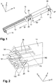
- the appended figures 1 to 7E briefly reviewed hereinbefore, present an example of a holding device 10 for a door leaf.
- the holding device 10 is essentially composed by a body 11 and a rod 12, described in more details hereinafter.
- the holding device 10 is configured so as to be able to hold a movable door leaf (not represented), pivotally mounted relative to a support (not represented), in an open configuration.
- the door leaf can switch, by pivoting relative to the support, between at least one closed configuration with respect to the support on the one hand and, on the other hand, one open configuration in which it is held in position thanks to the holding device 10.
- the door leaf also presents the capability of being open, always by pivoting relative to the support, beyond the aforementioned open configuration, up to a maximum open configuration. The passage from the open configuration to the maximum open configuration is intended to control the release of the holding device 10 in order to enable a return of the door leaf back to the closed configuration, this return being otherwise prevented.
- the holding device 10 finds application in particular in the motor vehicles field where the door leaf may be a front hood or a rear hatchback of the vehicle whereas the support on which the door leaf is pivotally mounted is for example an element of the body of the vehicle.
- the holding device described in this document may be used in association with a movable door leaf used in the furniture field such as for example in the manufacture of a coffer, in the household appliances field such as for example in the manufacture of a freezer or a washing machine, or still in the door- and window-frames field such as for example in the manufacture of certain windows, typically for the production of certain travel trailers.
- the body 11 presents a general tubular shape delimiting an internal passage area 13.
- the rod 12 is slidably mounted within the internal passage area 13 delimited by the body 11 so as to be able to slide along a longitudinal direction denoted X, orientated along the axis of the tubular shape of the body 11.
- the sliding of the rod 12 may take place either in a first direction S1 corresponding to a direction tending to extend the rod 12 out of the body 11, or in a second direction S2 corresponding to a direction tending to retract the rod 12 into the body 11.
- an orthogonal spatial system is associated to the holding device 10, including, in addition to the longitudinal direction X, a lateral direction Y perpendicular to the longitudinal direction X and a transverse direction Z perpendicular to the longitudinal direction X and to the lateral direction Y.
- the section of the body 11 is provided for example so as to present over at least one portion of its length, a shape matching with the external shape of the section of the rod 12, for example with generally rectangular shapes as represented in the figures, in order to avoid a relative rotation of the rod 12 and the body 11 around the longitudinal direction X.
- the body 11 may also be provided to be formed as an integral part made in one piece, in the same manner as the rod 12.
- the body 11 and the rod 12 may be obtained through a molding operation or through a 3D-printing operation, for example using a polyamide, polyester or polyoxymethylene type plastic material.
- the body 11 delimits a first fastening member 14 for pivotally fastening the body 11 either on the door leaf, or on the support.
- the first fastening member 14 has the advantage of not requiring any assembly operation with respect to the rest of the body 11.
- the rod 12 delimits a second fastening member 15 for pivotally fastening the rod 12 either on the support in the case where the body 11 is mounted on the door leaf thanks to the first fastening member 14, or on the door leaf in the case where the body 11 is mounted on the support thanks to the first fastening member 14.
- the second fastening member 15, which is integral with the rest of the rod 12, extends for example externally in projection along the lateral direction Y at the level of a distal longitudinal end of the rod 12, that is to say the longitudinal end opposite to the proximal longitudinal end which is inserted into the body 11.
- the second fastening member 15 has the advantage of not requiring any assembly operation with respect to the rest of the rod 12.
- each of the first fastening member 14 and the second fastening member 15 may be in the form of a substantially cylindrical tubular pin, provided with two transverse slots 27 to delimit two deformable portions 28.
- Each deformable portion 28 may be shaped so as to delimit a shoulder which is intended to hook on a rear face of a pierced wall of the support or of the door leaf.
- the invention also concerns the arrangement comprising the support, the door leaf pivotally movable relative to the support so as to switch between at least a closed configuration and an open configuration and at least one such holding device 10 whose first fastening member 14 delimited by the body 11 is pivotally fastened on an element selected among the door leaf and the support and whose second fastening member 15 delimited by the rod 12 is fastened on the other element selected among the door leaf and the support.
- the rod 12 When sliding relative to the body 11, the rod 12 may occupy at least one first retracted position (not represented) corresponding to the situation where the door leaf adopts the closed configuration with respect to the support and a second partially extended position corresponding to the situation where the door leaf adopts the open configuration with respect to the support.
- the rod 12 occupies the second position in Figure 1 and in Figure 7B .
- the holding device 10 allows holding the door leaf in the open configuration with specific blocking means whose release is automatically performed through a displacement of the door leaf from the open configuration to the aforementioned maximum open configuration.
- the rod 12 is slidably driven from the second partially extended position up to a third fully extended position which will be detailed later on.
- the release of the specific blocking means results from the displacement of the rod 12 in the first direction S1 from the second position to the third position.
- the rod 12 is capable of occupying the third fully extended position through a longitudinal sliding along the direction X from the second position in the first direction S1 which is opposite to the second direction S2 leading to the first position.
- the body 11 internally delimits at least one stop abutment 16 intended to longitudinally stop the rod 12 only in the second direction S2 and the rod 12 delimits at least one blocking notch 17 capable of switching between a laterally retracted configuration toward the inside of the rod 12 and a laterally deployed configuration toward the outside of the rod 12.
- the concerned blocking notch 17 In the retracted configuration, the concerned blocking notch 17 is stowed into the rod 12 along the lateral direction Y whereas in the deployed configuration, the blocking notch 17 projects laterally with respect to the rest of the rod 12.
- the longitudinal sliding of the rod 12 from the first position to the second position according to the first direction S1 allows placing said at least one blocking notch 17 automatically in its deployed configuration, adopted in the second position of the rod 12, and in which this blocking notch 17 bears longitudinally against the stop abutment 16 so as to block unidirectionally (in the second direction S2) the rod 12 along the longitudinal direction X in its second position and to prevent the sliding of the rod 12 in the direction of the first position.
- the number of blocking notches 17 can be equal to two as represented, or equal to a number greater than or equal to three.
- the two blocking notches 17 independent of each other are formed on two lateral faces of the rod 12 opposite to each other along the lateral direction Y.
- each blocking notch 17 delimits a lateral bearing shoulder 18 engaging with at least one linear stop system 19 delimited by the body 11 in the internal passage area 13 during a longitudinal sliding of the rod 12 according to the second direction S2 so as to switch from the third position to a fourth position longitudinally located between the first position and the second position ( Figure 7A ).
- Each lateral bearing shoulder 18 extends in projection along the lateral direction Y in the direction of the inside of the rod 12.
- the body 11 delimits two distinct linear stop systems 19, arranged facing each other in the transverse direction Z while being formed in walls of the body 11 transversely opposite to each other.
- the holding device 10 is arranged so that each of the lateral bearing shoulders 18 engages simultaneously into the two linear stop systems 19 during the sliding of the rod 12 from the third position to the fourth position. Nonetheless, the number of linear stop systems 19 still may be strictly equal to one.
- the simultaneous cooperation of the two lateral bearing shoulders 18 with the two linear stop systems 19 is illustrated by Figure 6 .
- Each linear stop system 19 is configured so as to control, by driving the blocking notch 17 at the level of its engaged lateral bearing shoulder 18, the passage and the holding of the blocking notch 17 in its retracted configuration during the longitudinal sliding of the rod 12 from the third position to the fourth position. This results in that, during this displacement of the rod 12 according to the second direction S2 from the third position to the fourth position, the blocking notches 17, which are placed and held in their laterally retracted configuration by the effect of the action imparted by each linear stop system 19, do not abut longitudinally against the longitudinal stop abutments 16 delimited by the body 11.
- the body 11 delimits two openings 20 formed throughout its two lateral faces.
- Each of the two blocking notches 17 is set in a corresponding one of these two openings 20 when the rod 12 occupies its second position, that is to say when the door leaf adopts its open configuration.
- each blocking notch 17 adopts its deployed configuration and bears longitudinally against the corresponding stop abutment 16 delimited by the body 11 (situation of Figure 7B and Figure 1 ).
- the door leaf being attached to the body 11 or to the rod 12, the weight of the door leaf guarantees the blocking of the blocking notches 17 with respect to the body 11.
- each blocking notch 17 is integral with the rod 12 and is linked to the rest of the rod 12 thanks to an area forming a hinge 24 for the blocking notch 17 with respect to the rest of the rod 12.
- the body 11 delimits an inner constriction protrusion 21 arranged adjacent to a longitudinal edge of each opening 20 along the longitudinal direction X and cooperating with an upper face of the blocking notch 17 so as to cause a progressive displacement of the blocking notch 17 to its retracted configuration when the rod 12 is displaced from the first position to the second position.
- the inner constriction protrusion 21 is configured so as to place the blocking notch 17 in its retracted configuration until the rod 12 reaches the second position, the blocking notch 17 being then released by the inner constriction protrusion as soon as the rod 12 reaches the second position during a displacement in the first direction S1.
- the rod 12 is displaced in the first direction S1 by the effect of a force F1 resulting, in turn, from an opening movement of the door leaf so as to displace it from the closed configuration to the open configuration.
- the stop abutment 16 may be constituted in particular by the connection area between the inner constriction protrusion 21 and the immediately adjacent opening 20.
- each opening 20 which is opposite to the longitudinal edge adjacent to the inner constriction protrusion 21 constitutes a bearing 22 cooperating with the upper face of the blocking notch 17 so as to automatically cause, through the sliding of the rod 12 in the first direction S1 from the second position to the third position, a progressive lateral displacement of the blocking notch 17 from its deployed configuration to a partially retracted configuration intermediate between the deployed configuration and the retracted configuration.
- This partially retracted configuration is held during the displacement of the rod 12 in the first direction S1 when switching from the second position to the third position.
- the rod 12 is displaced in the first direction by the effect of a force F2 resulting, in turn, from the opening movement of the door leaf so as to displace it from the open configuration to the already mentioned maximum open configuration.
- each blocking notch 17 adopts its retracted configuration as has been already described before because of the presence of the lateral bearing shoulders 18 and the linear stop systems 19.
- each blocking notch 17 adopts its partially retracted configuration when the rod 12 is positioned between the fourth position and the first position, regardless of the sliding direction S1, S2 of the rod 12.
- the partially retracted configuration adopted by each blocking notch 17 results from its natural tendency to be elastically biased toward its deployed configuration because of the presence of the area forming a hinge 24, without being able to reach the deployed configuration because of internal contact of the upper face of the blocking notch 17 against one of the lateral faces of the body 11.
- each blocking notch 17 may advantageously present an inclined profile in the same manner as a cutaway, orientated so as to get close to the inside of the rod 12 along the lateral direction Y by getting close to the distal end of the rod 12.
- the inner constriction protrusion 21 presents a matching cutaway.
- the rod 12 comprises at least one stop 23 arranged so as to abut longitudinally against the inner constriction protrusions 21 when the rod 12 occupies its third position in order to block the sliding movement of the rod 12 unidirectionally in the first direction S1.
- each of the two linear stop systems 19 comprises two linear stops formed in projection toward the inside of the internal passage area 13 so as to delimit two distinct bearing edges 191, 192 extending substantially parallel to each other along the longitudinal direction X and facing each other along the lateral direction Y with a gap 26 interposed therebetween.
- the cooperation between the lateral bearing shoulder 18 of each of the two blocking notches 17 and each linear stop system 19 results from a lateral contact between this lateral bearing shoulder 18, then positioned in the gap 26, and the corresponding one of the two bearing edges 191, 192.
- each linear stop system 19 are in the form of two non-straight walls obtained by cutting and then folding inwardly the internal passage area 13; this is the reason of the presence of the openings 25 in the embodiment of Figures 1 to 7E .
- each of the two bearing edges 191, 192 of each linear stop system 19 presents a profile progressively converging toward the other one of the two bearing edges 191, 192 of this system by getting dose to the first fastening member 14 of the body 11 so that the gap 26 delimited between the two bearing edges 191, 192 presents a width considered laterally which progressively decreases over at least one portion of the longitudinal length of the bearing edges 191, 192 by getting close to the first fastening member 14 of the body 11 until reaching a minimum value denoted E2.
- the variation of the lateral width of the gap 26 to pass from the maximum value denoted E1 (at the inlet of the linear stop system 19 when the rod slides in the second direction S2 so as to switch from the third position to the fourth position) down to the minimum value E2 is adapted to control the progressive passage and holding of each of the two blocking notches 17 to its retracted configuration during the passage of the rod 12 from the third position to the fourth position.
- the previously-described holding device 10, whose release is automatically performed by continuing opening the door leaf beyond the open configuration previously held by the holding device 10 itself, is advantageously simple to manufacture and use, is economical and reliable.
- the blocking means capable of holding the door leaf in the open configuration and their automatic unlocking means are all integrated into the body 11 and into the rod 12, which allows getting rid of assembly operations and reduces the costs.
- the operation of these blocking means and of their unlocking means is very reliable, freeing from any possible inadvertent jamming.
Landscapes
- Engineering & Computer Science (AREA)
- Mechanical Engineering (AREA)
- Lock And Its Accessories (AREA)
- Power-Operated Mechanisms For Wings (AREA)
Abstract
Description
- The present invention concerns a holding device for a door leaf, capable of holding a door leaf pivotally movable relative to a support in an open configuration, the holding device comprising a tubular body delimiting an internal passage area and delimiting a first fastening member for pivotally fastening the body on an element selected among the door leaf and the support, and a rod slidably mounted within the internal passage area along a longitudinal direction and delimiting a second fastening member for pivotally fastening the rod on the other element selected among the door leaf and the support, the rod being capable of occupying a first retracted position corresponding to a closed configuration of the door leaf with respect to the support and a second partially extended position corresponding to the open configuration of the door leaf with respect to the support.
- The field of the invention is limited to a holding device capable of holding the door leaf in an open configuration with specific blocking means whose release is automatically performed by continuing opening the door leaf beyond the open configuration previously held by the holding device.
- The invention also concerns an arrangement comprising a support, a door leaf pivotally movable relative to the support so as to switch between at least a closed configuration and an open configuration and at least one such holding device whose first fastening member delimited by the body is pivotally fastened on an element selected among the door leaf and the support and whose second fastening member delimited by the rod is fastened on the other element selected among the door leaf and the support.
- The invention finds application in particular in the motor vehicles field where the door leaf is a front hood or a rear hatchback and the support is an element of the body of the vehicle. Nonetheless, it may be considered to apply the holding device described in this document to other technical fields such as for example furniture, household appliances or door- and window-frames.
- There are numerous solutions for holding a door leaf pivotally movable relative to a support in an open configuration. Among these solutions, there are some ones whose release is automatically performed simply by continuing opening the door leaf beyond the open configuration held by the holding device.
- But the known solutions are complex, require numerous and sometimes tricky assembly operations, which increase their manufacturing and prime costs, and sometimes exhibit still perfectible reliability and ergonomics.
- For example, the document
US2566182A describes a holding device with a body and a rod on which blocking elements are attached and assembled. These blocking elements allow holding the rod in an extended configuration with respect to the body so as to hold the rear hatchback of a vehicle in an open configuration. The release of the blocking elements is achieved by continuing opening the rear hatchback beyond the open configuration previously held by the blocking elements. - In addition to the drawbacks already listed hereinabove, as a result of the necessity of having to assemble the parts constitutive of the blocking elements on the body and on the rod, a main drawback of this solution lies in the rotating kinematics of the blocking elements which, unfortunately, may inadvertently jam during this rotation. This jamming may result in blocking the hatchback in an open configuration and make it impossible for the user to replace the hatchback in the closed configuration, which is obviously not satisfactory in use.
- The present invention aims at providing a holding device for a door leaf, configured so as to hold in an open configuration a door leaf pivotally movable relative to a support, which addresses all or part of the aforementioned problems.
- In particular, the aim of the invention is to provide a holding device of the aforementioned type, that is to say whose release is automatically performed by continuing opening the door leaf beyond the open configuration, which is simple to manufacture and to use, which is economical and reliable
- This aim may be reached by providing a holding device for a door leaf, capable of holding a door leaf pivotally movable relative to a support in an open configuration, the holding device comprising a tubular body delimiting an internal passage area and delimiting a first fastening member for pivotally fastening the body on either one of the door leaf and the support, and a rod slidably mounted within the internal passage area along a longitudinal direction and delimiting a second fastening member for pivotally fastening the rod on the other one of the door leaf and the support, the rod being capable of occupying a first retracted position corresponding to a closed configuration of the door leaf with respect to the support and a second partially extended position corresponding to the open configuration of the door leaf with respect to the support, the body internally delimiting at least one longitudinal stop abutment and the rod delimiting at least one blocking notch capable of switching between a laterally retracted configuration and a laterally deployed configuration, the longitudinal sliding of the rod from the first position to the second position automatically placing the blocking notch in its deployed configuration in which the blocking notch bears longitudinally against the stop abutment so as to unidirectionally block the rod longitudinally in its second position and to prevent the sliding of the rod in the direction of its first position, the rod being capable of occupying a third fully extended position through a longitudinal sliding from the second position in a direction opposite to the first position, the blocking notch delimiting a lateral bearing shoulder engaging with at least one linear stop system delimited by the body in the internal passage area during a longitudinal sliding of the rod from the third position to a fourth position longitudinally located between the first position and the second position, the linear stop system being configured so as to control, by driving the blocking notch at the level of its lateral bearing shoulder, the passage and the holding of the blocking notch in its retracted configuration during said longitudinal sliding of the rod from the third position to the fourth position.
- The holding device may also present the following advantageous features, considered separately or in combination.
- The body delimits at least one opening formed throughout one of its faces, into which the blocking notch is set when the rod occupies its second position in which the blocking notch, occupying its laterally deployed configuration, bears longitudinally against the corresponding stop abutment delimited by the body.
- The body delimits at least one inner constriction protrusion arranged adjacent to a longitudinal edge of said at least one opening along the longitudinal direction and cooperating with an upper face of the blocking notch so as to cause a progressive displacement of the blocking notch to its retracted configuration when the rod is displaced from the first position to the second position, until achieving a longitudinal bearing of the blocking notch against the stop abutment, resulting from an elastic lateral return of the blocking notch back to its deployed configuration after the inner constriction protrusion so as to be set into said at least one opening.
- Said at least one stop abutment is constituted by a junction area between said at least one inner constriction protrusion and said at least one opening.
- The longitudinal edge of said at least one opening which is opposite to the inner constriction protrusion constitutes a bearing cooperating with the upper face of the blocking notch so as to automatically cause, through the sliding of the rod from the second position to the third position, a progressive displacement of the blocking notch from its deployed configuration to a partially retracted configuration intermediate between the deployed configuration and the retracted configuration.
- The rod comprises at least one stop arranged so as to abut longitudinally against said at least one inner constriction protrusion delimited by the body when the rod occupies its third position and to block the sliding movement of the rod unidirectionally in a direction opposite to the direction allowing sliding toward the second position.
- Said at least one blocking notch is integral with the rod and is linked to the rest of the rod thanks to an area forming a hinge for the blocking notch with respect to the rest of the rod.
- The rod delimits two independent blocking notches arranged on two opposite lateral faces of the rod and said at least one linear stop system comprises two linear stops formed in projection toward the inside of the internal passage area so as to delimit two distinct bearing edges extending substantially parallel to each other along the longitudinal direction and facing each other laterally with a gap interposed therebetween, the cooperation between the lateral bearing shoulder of each of the two blocking notches and said at least one linear stop system resulting from a lateral contact between the lateral bearing shoulder of this blocking notch positioned in the gap and the corresponding one of the two bearing edges.
- Each of the two bearing edges presents a profile progressively converging toward the other one of the two bearing edges by getting close to the first fastening member of the body so that the gap delimited between the two bearing edges presents a lateral width progressively decreasing over at least one portion of the longitudinal length of the bearing edges by getting close to the first fastening member of the body until reaching a minimum value, the variation of the lateral width of the gap to the minimum value being adapted to control the progressive passage and holding of each of the two blocking notches to its retracted configuration during the passage of the rod from the third position to the fourth position.
- The invention also relates to an arrangement comprising a support, a door leaf pivotally movable relative to the support so as to switch between at least a closed configuration and an open configuration and at least one such holding device whose first fastening member delimited by the body is pivotally fastened on either one of the door leaf and the support and whose second fastening member delimited by the rod is fastened on the other one of the door leaf and the support.
- Other aspects, aims, advantages and features of the invention will appear better upon reading the following detailed description of preferred embodiments thereof, given as a non-limiting example, and made with reference to the appended drawings in which:
-
Figure 1 is a perspective view of an example of a holding device according to the invention, -
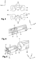
Figures 2 and3 show a portion of the body used in the holding device ofFigure 1 , at the level of a sectional plane denoted P1 inFigure 2 , respectively in perspective view and according to the longitudinal direction X, -
Figure 4 partially represents the rod used in the holding device ofFigure 1 , at the level of a proximal end of the rod intended to be inserted into the body shown in the previous figures, -
Figures 5 and6 show a portion of the rod, at the level of a sectional plane denoted P2 inFigure 5 , respectively in perspective view and according to the longitudinal direction X, -
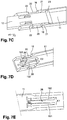
Figures 7A to 7C partially represent the holding device in section according to a sectional plane P3 shown inFigure 2 , for different positions occupied by the rod, -
Figures 7D and 7E partially illustrate the body in section according to the sectional plane P3, at the level of the proximal end into which the rod is intended to be inserted. - The appended
figures 1 to 7E , briefly reviewed hereinbefore, present an example of aholding device 10 for a door leaf. - The
holding device 10 is essentially composed by abody 11 and arod 12, described in more details hereinafter. - In particular, the
holding device 10 is configured so as to be able to hold a movable door leaf (not represented), pivotally mounted relative to a support (not represented), in an open configuration. In other words, the door leaf can switch, by pivoting relative to the support, between at least one closed configuration with respect to the support on the one hand and, on the other hand, one open configuration in which it is held in position thanks to theholding device 10. The door leaf also presents the capability of being open, always by pivoting relative to the support, beyond the aforementioned open configuration, up to a maximum open configuration. The passage from the open configuration to the maximum open configuration is intended to control the release of theholding device 10 in order to enable a return of the door leaf back to the closed configuration, this return being otherwise prevented. - The
holding device 10 finds application in particular in the motor vehicles field where the door leaf may be a front hood or a rear hatchback of the vehicle whereas the support on which the door leaf is pivotally mounted is for example an element of the body of the vehicle. Alternatively, the holding device described in this document may be used in association with a movable door leaf used in the furniture field such as for example in the manufacture of a coffer, in the household appliances field such as for example in the manufacture of a freezer or a washing machine, or still in the door- and window-frames field such as for example in the manufacture of certain windows, typically for the production of certain travel trailers. - The
body 11 presents a general tubular shape delimiting aninternal passage area 13. Therod 12 is slidably mounted within theinternal passage area 13 delimited by thebody 11 so as to be able to slide along a longitudinal direction denoted X, orientated along the axis of the tubular shape of thebody 11. The sliding of therod 12 may take place either in a first direction S1 corresponding to a direction tending to extend therod 12 out of thebody 11, or in a second direction S2 corresponding to a direction tending to retract therod 12 into thebody 11. - For a better understanding of the general layout of the
body 11 and therod 12, an orthogonal spatial system is associated to theholding device 10, including, in addition to the longitudinal direction X, a lateral direction Y perpendicular to the longitudinal direction X and a transverse direction Z perpendicular to the longitudinal direction X and to the lateral direction Y. - In order to ensure the sliding guidance of the
rod 12 relative to thebody 11, the section of thebody 11, as viewed in a sectional plane (Y, Z), is provided for example so as to present over at least one portion of its length, a shape matching with the external shape of the section of therod 12, for example with generally rectangular shapes as represented in the figures, in order to avoid a relative rotation of therod 12 and thebody 11 around the longitudinal direction X. - For reasons relating to manufacturing simplicity and costs, the
body 11 may also be provided to be formed as an integral part made in one piece, in the same manner as therod 12. Typically, thebody 11 and therod 12 may be obtained through a molding operation or through a 3D-printing operation, for example using a polyamide, polyester or polyoxymethylene type plastic material. - The
body 11 delimits afirst fastening member 14 for pivotally fastening thebody 11 either on the door leaf, or on the support. Thefirst fastening member 14, which is integral with the rest of thebody 11, extends for example externally in projection along the lateral direction Y at the level of a distal longitudinal end of thebody 11, that is to say the longitudinal end opposite to the proximal longitudinal end into which therod 12 is inserted. Thefirst fastening member 14 has the advantage of not requiring any assembly operation with respect to the rest of thebody 11. - The
rod 12 delimits asecond fastening member 15 for pivotally fastening therod 12 either on the support in the case where thebody 11 is mounted on the door leaf thanks to the first fasteningmember 14, or on the door leaf in the case where thebody 11 is mounted on the support thanks to thefirst fastening member 14. Thesecond fastening member 15, which is integral with the rest of therod 12, extends for example externally in projection along the lateral direction Y at the level of a distal longitudinal end of therod 12, that is to say the longitudinal end opposite to the proximal longitudinal end which is inserted into thebody 11. Thesecond fastening member 15 has the advantage of not requiring any assembly operation with respect to the rest of therod 12. - In order to obtain a setting and a fastening of the
holding device 10 which are effective and at a low cost, each of thefirst fastening member 14 and thesecond fastening member 15 may be in the form of a substantially cylindrical tubular pin, provided with twotransverse slots 27 to delimit two deformable portions 28. Each deformable portion 28 may be shaped so as to delimit a shoulder which is intended to hook on a rear face of a pierced wall of the support or of the door leaf. - The invention also concerns the arrangement comprising the support, the door leaf pivotally movable relative to the support so as to switch between at least a closed configuration and an open configuration and at least one
such holding device 10 whosefirst fastening member 14 delimited by thebody 11 is pivotally fastened on an element selected among the door leaf and the support and whosesecond fastening member 15 delimited by therod 12 is fastened on the other element selected among the door leaf and the support. - When sliding relative to the
body 11, therod 12 may occupy at least one first retracted position (not represented) corresponding to the situation where the door leaf adopts the closed configuration with respect to the support and a second partially extended position corresponding to the situation where the door leaf adopts the open configuration with respect to the support. Therod 12 occupies the second position inFigure 1 and inFigure 7B . - The
holding device 10 allows holding the door leaf in the open configuration with specific blocking means whose release is automatically performed through a displacement of the door leaf from the open configuration to the aforementioned maximum open configuration. During this displacement of the door leaf, therod 12 is slidably driven from the second partially extended position up to a third fully extended position which will be detailed later on. In concrete terms, the release of the specific blocking means results from the displacement of therod 12 in the first direction S1 from the second position to the third position. In order to ensure such an operation, therod 12 is capable of occupying the third fully extended position through a longitudinal sliding along the direction X from the second position in the first direction S1 which is opposite to the second direction S2 leading to the first position. - To this end, the
body 11 internally delimits at least onestop abutment 16 intended to longitudinally stop therod 12 only in the second direction S2 and therod 12 delimits at least one blockingnotch 17 capable of switching between a laterally retracted configuration toward the inside of therod 12 and a laterally deployed configuration toward the outside of therod 12. In the retracted configuration, the concerned blockingnotch 17 is stowed into therod 12 along the lateral direction Y whereas in the deployed configuration, the blockingnotch 17 projects laterally with respect to the rest of therod 12. - The longitudinal sliding of the
rod 12 from the first position to the second position according to the first direction S1 allows placing said at least one blockingnotch 17 automatically in its deployed configuration, adopted in the second position of therod 12, and in which this blockingnotch 17 bears longitudinally against thestop abutment 16 so as to block unidirectionally (in the second direction S2) therod 12 along the longitudinal direction X in its second position and to prevent the sliding of therod 12 in the direction of the first position. The number of blockingnotches 17 can be equal to two as represented, or equal to a number greater than or equal to three. For example, the twoblocking notches 17 independent of each other are formed on two lateral faces of therod 12 opposite to each other along the lateral direction Y. - Advantageously, each blocking
notch 17 delimits alateral bearing shoulder 18 engaging with at least onelinear stop system 19 delimited by thebody 11 in theinternal passage area 13 during a longitudinal sliding of therod 12 according to the second direction S2 so as to switch from the third position to a fourth position longitudinally located between the first position and the second position (Figure 7A ). Eachlateral bearing shoulder 18 extends in projection along the lateral direction Y in the direction of the inside of therod 12. - According to a non limiting embodiment as illustrated in
Figure 3 , promoting an effective and reliable operation of the holdingdevice 10, thebody 11 delimits two distinctlinear stop systems 19, arranged facing each other in the transverse direction Z while being formed in walls of thebody 11 transversely opposite to each other. The holdingdevice 10 is arranged so that each of the lateral bearing shoulders 18 engages simultaneously into the twolinear stop systems 19 during the sliding of therod 12 from the third position to the fourth position. Nonetheless, the number oflinear stop systems 19 still may be strictly equal to one. The simultaneous cooperation of the two lateral bearing shoulders 18 with the twolinear stop systems 19 is illustrated byFigure 6 . - Each
linear stop system 19 is configured so as to control, by driving the blockingnotch 17 at the level of its engagedlateral bearing shoulder 18, the passage and the holding of the blockingnotch 17 in its retracted configuration during the longitudinal sliding of therod 12 from the third position to the fourth position. This results in that, during this displacement of therod 12 according to the second direction S2 from the third position to the fourth position, the blockingnotches 17, which are placed and held in their laterally retracted configuration by the effect of the action imparted by eachlinear stop system 19, do not abut longitudinally against thelongitudinal stop abutments 16 delimited by thebody 11. - According to a particular embodiment, the
body 11 delimits twoopenings 20 formed throughout its two lateral faces. Each of the twoblocking notches 17 is set in a corresponding one of these twoopenings 20 when therod 12 occupies its second position, that is to say when the door leaf adopts its open configuration. When therod 12 occupies the second position, each blockingnotch 17 adopts its deployed configuration and bears longitudinally against thecorresponding stop abutment 16 delimited by the body 11 (situation ofFigure 7B andFigure 1 ). The door leaf being attached to thebody 11 or to therod 12, the weight of the door leaf guarantees the blocking of the blockingnotches 17 with respect to thebody 11. - According to a particular embodiment, each blocking
notch 17 is integral with therod 12 and is linked to the rest of therod 12 thanks to an area forming ahinge 24 for the blockingnotch 17 with respect to the rest of therod 12. - As shown in
Figures 7A to 7C , thebody 11 delimits aninner constriction protrusion 21 arranged adjacent to a longitudinal edge of eachopening 20 along the longitudinal direction X and cooperating with an upper face of the blockingnotch 17 so as to cause a progressive displacement of the blockingnotch 17 to its retracted configuration when therod 12 is displaced from the first position to the second position. Theinner constriction protrusion 21 is configured so as to place the blockingnotch 17 in its retracted configuration until therod 12 reaches the second position, the blockingnotch 17 being then released by the inner constriction protrusion as soon as therod 12 reaches the second position during a displacement in the first direction S1. InFigure 7A , therod 12 is displaced in the first direction S1 by the effect of a force F1 resulting, in turn, from an opening movement of the door leaf so as to displace it from the closed configuration to the open configuration. - When the second position is reached (
Figure 7B ), a longitudinal bearing of the blockingnotch 17 against thestop abutment 16, resulting from an elastic lateral return of the blockingnotch 17 back to its deployed configuration, is obtained after having longitudinally overpassed theinner constriction protrusion 21. By adopting its deployed configuration after having been released by theinner constriction protrusion 21, the blockingnotch 17 is set in thecorresponding opening 20. - In practice, the
stop abutment 16 may be constituted in particular by the connection area between theinner constriction protrusion 21 and the immediatelyadjacent opening 20. - Referring to
Figure 7C , the longitudinal edge of each opening 20 which is opposite to the longitudinal edge adjacent to theinner constriction protrusion 21 constitutes abearing 22 cooperating with the upper face of the blockingnotch 17 so as to automatically cause, through the sliding of therod 12 in the first direction S1 from the second position to the third position, a progressive lateral displacement of the blockingnotch 17 from its deployed configuration to a partially retracted configuration intermediate between the deployed configuration and the retracted configuration. This partially retracted configuration is held during the displacement of therod 12 in the first direction S1 when switching from the second position to the third position. InFigure 7C , therod 12 is displaced in the first direction by the effect of a force F2 resulting, in turn, from the opening movement of the door leaf so as to displace it from the open configuration to the already mentioned maximum open configuration. - Conversely, when the
rod 12 is displaced in the second direction S2 so as to switch from the third position to the second position, and even to the fourth position, each blockingnotch 17 adopts its retracted configuration as has been already described before because of the presence of the lateral bearing shoulders 18 and thelinear stop systems 19. - It is also specified that each blocking
notch 17 adopts its partially retracted configuration when therod 12 is positioned between the fourth position and the first position, regardless of the sliding direction S1, S2 of therod 12. In practice, the partially retracted configuration adopted by each blockingnotch 17 results from its natural tendency to be elastically biased toward its deployed configuration because of the presence of the area forming ahinge 24, without being able to reach the deployed configuration because of internal contact of the upper face of the blockingnotch 17 against one of the lateral faces of thebody 11. - For an effective and progressive operation of each blocking
notch 17 on the one hand with theinner constriction protrusion 21 and on the other hand with thebearing 22, the upper face of each blockingnotch 17 may advantageously present an inclined profile in the same manner as a cutaway, orientated so as to get close to the inside of therod 12 along the lateral direction Y by getting close to the distal end of therod 12. Theinner constriction protrusion 21 presents a matching cutaway. - As shown for example in
Figures 4 and 5 , therod 12 comprises at least onestop 23 arranged so as to abut longitudinally against theinner constriction protrusions 21 when therod 12 occupies its third position in order to block the sliding movement of therod 12 unidirectionally in the first direction S1. - Referring now to
Figures 2 ,3 ,7D and 7E , each of the twolinear stop systems 19 comprises two linear stops formed in projection toward the inside of theinternal passage area 13 so as to delimit two distinct bearing edges 191, 192 extending substantially parallel to each other along the longitudinal direction X and facing each other along the lateral direction Y with agap 26 interposed therebetween. The cooperation between thelateral bearing shoulder 18 of each of the twoblocking notches 17 and eachlinear stop system 19 results from a lateral contact between thislateral bearing shoulder 18, then positioned in thegap 26, and the corresponding one of the two bearingedges - For example, the two linear stops constitutive of each
linear stop system 19 are in the form of two non-straight walls obtained by cutting and then folding inwardly theinternal passage area 13; this is the reason of the presence of theopenings 25 in the embodiment ofFigures 1 to 7E . - According to a particular embodiment, each of the two bearing
edges linear stop system 19 presents a profile progressively converging toward the other one of the two bearingedges first fastening member 14 of thebody 11 so that thegap 26 delimited between the two bearingedges first fastening member 14 of thebody 11 until reaching a minimum value denoted E2. The variation of the lateral width of thegap 26 to pass from the maximum value denoted E1 (at the inlet of thelinear stop system 19 when the rod slides in the second direction S2 so as to switch from the third position to the fourth position) down to the minimum value E2 is adapted to control the progressive passage and holding of each of the twoblocking notches 17 to its retracted configuration during the passage of therod 12 from the third position to the fourth position. - The previously-described
holding device 10, whose release is automatically performed by continuing opening the door leaf beyond the open configuration previously held by the holdingdevice 10 itself, is advantageously simple to manufacture and use, is economical and reliable. The blocking means capable of holding the door leaf in the open configuration and their automatic unlocking means are all integrated into thebody 11 and into therod 12, which allows getting rid of assembly operations and reduces the costs. The operation of these blocking means and of their unlocking means is very reliable, freeing from any possible inadvertent jamming.
Claims (10)
- A holding device (10) for a door leaf, capable of holding a door leaf pivotally movable relative to a support in an open configuration, the holding device (10) comprising a tubular body (11) delimiting an internal passage area (13) and delimiting a first fastening member (14) for pivotally fastening the body (11) on either one of the door leaf and the support, and a rod (12) slidably mounted within the internal passage area (13) along a longitudinal direction (X) and delimiting a second fastening member (15) for pivotally fastening the rod (12) on the other one of the door leaf and the support, the rod (12) being capable of occupying a first retracted position corresponding to a closed configuration of the door leaf with respect to the support and a second partially extended position corresponding to the open configuration of the door leaf with respect to the support, the body (11) internally delimiting at least one longitudinal stop abutment (16) and the rod (12) delimiting at least one blocking notch (17) capable of switching between a laterally retracted configuration and a laterally deployed configuration, the longitudinal sliding of the rod (12) from the first position to the second position automatically placing the blocking notch (17) in its deployed configuration in which the blocking notch (17) bears longitudinally against the stop abutment (16) so as to block unidirectionally the rod (12) longitudinally in its second position and to prevent the sliding of the rod (12) in the direction of its first position, the rod (12) being capable of occupying a third fully extended position through a longitudinal sliding from the second position in a direction (S1) opposite to the first position, the blocking notch (17) delimiting a lateral bearing shoulder (18) engaging with at least one linear stop system (19) delimited by the body (11) in the internal passage area (13) during a longitudinal sliding of the rod (12) from the third position to a fourth position longitudinally located between the first position and the second position, the linear stop system (19) being configured so as to control, by driving the blocking notch (17) at the level of its lateral bearing shoulder (18), the passage and the holding of the blocking notch (17) in its retracted configuration during said longitudinal sliding of the rod (12) from the third position to the fourth position.
- The holding device (10) according to claim 1, characterized in that the body (11) delimits at least one opening (20) formed throughout one of its faces, into which the blocking notch (17) is set when the rod (12) occupies its second position in which the blocking notch (17), occupying its laterally deployed configuration, bears longitudinally against the corresponding stop abutment (16) delimited by the body (11).
- The holding device (10) according to claim 2, characterized in that the body (11) delimits at least one inner constriction protrusion (21) arranged adjacent to a longitudinal edge of said at least one opening (20) along the longitudinal direction (X) and cooperating with an upper face of the blocking notch (17) so as to cause a progressive displacement of the blocking notch (17) to its retracted configuration when the rod (12), is displaced from the first position to the second position.
- The holding device (10) according to claim 3, characterized in that said at least one stop abutment (16) is constituted by a junction area between said at least one inner constriction protrusion (21) and said at least one opening (20).
- The holding device (10) according to any one of claims 3 or 4, characterized in that the longitudinal edge of said at least one opening (20) which is opposite to the inner constriction protrusion (21) constitutes a bearing (22) cooperating with the upper face of the blocking notch (17) so as to automatically cause, through the sliding of the rod (12) from the second position to the third position, a progressive displacement of the blocking notch (17) from its deployed configuration to a partially retracted configuration intermediate between the deployed configuration and the retracted configuration.
- The holding device (10) according to any one of claims 3 to 5, characterized in that the rod (12) comprises at least one stop (23) arranged so as to abut longitudinally against said at least one inner constriction protrusion (21) delimited by the body (11) when the rod (12) occupies its third position and to block the sliding movement of the rod (12) unidirectionally in a direction (S1) opposite to the direction (S2) allowing sliding to the second position.
- The holding device (10) according to any one of claims 1 to 6, characterized in that said at least one blocking notch (17) is integral with the rod (12) and is linked to the rest of the rod (12) thanks to an area forming a hinge (24) for the blocking notch (17) with respect to the rest of the rod (12).
- The holding device (10) according to any one of claims 1 to 7, characterized in that the rod (12) delimits two independent blocking notches (17) arranged on two opposite lateral faces of the rod (12) and in that said at least one linear stop system (19) comprises two linear stops formed in projection toward the inside of the internal passage area (13) so as to delimit two distinct bearing edges (191, 192) extending substantially parallel to each other along the longitudinal direction (X) and facing each other laterally with a gap (26) interposed therebetween, the cooperation between the lateral bearing shoulder (18) of each of the two blocking notches (17) and said at least one linear stop system (19) resulting from a lateral contact between the lateral bearing shoulder (18) of this blocking notch positioned in the gap (26) and the corresponding one of the two bearing edges (191, 192).
- The holding device (10) according to claim 8, characterized in that each of the two bearing edges (191, 192) presents a profile progressively converging toward the other one of the two bearing edges (191, 192) by getting close to the first fastening member (14) of the body (11) so that the gap (26) delimited between the two bearing edges (191, 192) presents a lateral width progressively decreasing over at least one portion of the longitudinal length of the bearing edges (191, 192) by getting close to the first fastening member (14) of the body (11) until reaching a minimum value (E2), the variation of the lateral width of the gap (26) to the minimum value (E2) being adapted to control the progressive passage and holding of each of the two blocking notches (17) to its retracted configuration during the passage of the rod (12) from the third position to the fourth position.
- An arrangement comprising a support, a door leaf pivotally movable relative to the support so as to switch between at least a closed configuration and an open configuration and at least one holding device (10) according to any one of the preceding claims whose first fastening member (14) delimited by the body (11) is pivotally fastened on either one of the door leaf and the support and whose second fastening member (15) delimited by the rod (12) is fastened on the other one of the door leaf and the support.
Priority Applications (1)
| Application Number | Priority Date | Filing Date | Title |
|---|---|---|---|
| EP18290040.7A EP3564470B1 (en) | 2018-04-30 | 2018-04-30 | Holding device for holding a door leaf in an open configuration releasable through a further opening of the door leaf |
Applications Claiming Priority (1)
| Application Number | Priority Date | Filing Date | Title |
|---|---|---|---|
| EP18290040.7A EP3564470B1 (en) | 2018-04-30 | 2018-04-30 | Holding device for holding a door leaf in an open configuration releasable through a further opening of the door leaf |
Publications (2)
| Publication Number | Publication Date |
|---|---|
| EP3564470A1 true EP3564470A1 (en) | 2019-11-06 |
| EP3564470B1 EP3564470B1 (en) | 2020-12-16 |
Family
ID=62386301
Family Applications (1)
| Application Number | Title | Priority Date | Filing Date |
|---|---|---|---|
| EP18290040.7A Active EP3564470B1 (en) | 2018-04-30 | 2018-04-30 | Holding device for holding a door leaf in an open configuration releasable through a further opening of the door leaf |
Country Status (1)
| Country | Link |
|---|---|
| EP (1) | EP3564470B1 (en) |
Citations (5)
| Publication number | Priority date | Publication date | Assignee | Title |
|---|---|---|---|---|
| US2566182A (en) | 1948-05-14 | 1951-08-28 | Gen Motors Corp | Automobile rear deck lid prop |
| DE2340912A1 (en) * | 1972-08-15 | 1974-02-28 | Michael Firth Robertshaw | DEVICE FOR RELEASABLE DETERMINATION OF SLIDING PARTS |
| DE2702615A1 (en) * | 1977-01-22 | 1978-07-27 | Mekuwa Metall Kunststoff | Telescopic stay for window or furniture flap - has internal catch loaded by spring and projecting ratchet |
| US4984331A (en) * | 1985-12-18 | 1991-01-15 | Richard Hucknall | Door holder including a removable cam |
| DE29500929U1 (en) * | 1995-01-21 | 1995-03-16 | Geiß, Peter, 66352 Großrosseln | Device for locking and unlocking a movable, elongated object with a fixed, elongated object |
-
2018
- 2018-04-30 EP EP18290040.7A patent/EP3564470B1/en active Active
Patent Citations (5)
| Publication number | Priority date | Publication date | Assignee | Title |
|---|---|---|---|---|
| US2566182A (en) | 1948-05-14 | 1951-08-28 | Gen Motors Corp | Automobile rear deck lid prop |
| DE2340912A1 (en) * | 1972-08-15 | 1974-02-28 | Michael Firth Robertshaw | DEVICE FOR RELEASABLE DETERMINATION OF SLIDING PARTS |
| DE2702615A1 (en) * | 1977-01-22 | 1978-07-27 | Mekuwa Metall Kunststoff | Telescopic stay for window or furniture flap - has internal catch loaded by spring and projecting ratchet |
| US4984331A (en) * | 1985-12-18 | 1991-01-15 | Richard Hucknall | Door holder including a removable cam |
| DE29500929U1 (en) * | 1995-01-21 | 1995-03-16 | Geiß, Peter, 66352 Großrosseln | Device for locking and unlocking a movable, elongated object with a fixed, elongated object |
Also Published As
| Publication number | Publication date |
|---|---|
| EP3564470B1 (en) | 2020-12-16 |
Similar Documents
| Publication | Publication Date | Title |
|---|---|---|
| KR102154721B1 (en) | Locking device | |
| CN105696880B (en) | Motor vehicle door handle arrangement with handle guide element | |
| US6988752B2 (en) | Pinless inside door handle assembly | |
| US10550610B2 (en) | Inside override emergency handle for door release | |
| US9347246B2 (en) | Opening and/or closing mechanism on doors, gates/flaps or the like, in particular on motor vehicles | |
| US10259295B2 (en) | Winding device | |
| WO2011120723A1 (en) | Connection device for the articulated connection of a wiper arm to a wiper blade | |
| US7303216B2 (en) | Latch assembly | |
| KR101662518B1 (en) | Latch struture of tail-gate | |
| US5703339A (en) | Safety switch | |
| EA014869B1 (en) | Armature system for a window, door or similar | |
| WO2000051149A1 (en) | Device for receiving and holding an identification provider, such as an electronic key, especially for an ignition-starter switch | |
| WO2014113213A1 (en) | An article for blind fastening to a support | |
| EP3564470B1 (en) | Holding device for holding a door leaf in an open configuration releasable through a further opening of the door leaf | |
| DE3336952A1 (en) | PUSH BUTTON LOCK, ESPECIALLY FOR LOCKING CAPS OF GLOVE COMPARTMENTS IN MOTOR VEHICLES | |
| CN102016205A (en) | Lock mechanism blocking device | |
| US5826709A (en) | Self-adjusting plunger switch | |
| EP2297417B1 (en) | Mechanism for locking a door of an electric household appliance | |
| EP2726690B1 (en) | Door locking device, particularly for electric household appliances | |
| DE102006047715A1 (en) | Locking device for locking the interior of a device and device with locking device | |
| CN216300939U (en) | Fixing device and vehicle decoration assembly | |
| US7607704B2 (en) | Push-pull latch bolt mechanism | |
| EP2543798B1 (en) | Automatically actuating lock | |
| MXPA06010168A (en) | One-piece cam and bolt housing for a deadbolt assembly. | |
| US1249176A (en) | Bolt. |
Legal Events
| Date | Code | Title | Description |
|---|---|---|---|
| STAA | Information on the status of an ep patent application or granted ep patent |
Free format text: STATUS: UNKNOWN |
|
| PUAI | Public reference made under article 153(3) epc to a published international application that has entered the european phase |
Free format text: ORIGINAL CODE: 0009012 |
|
| STAA | Information on the status of an ep patent application or granted ep patent |
Free format text: STATUS: THE APPLICATION HAS BEEN PUBLISHED |
|
| AK | Designated contracting states |
Kind code of ref document: A1 Designated state(s): AL AT BE BG CH CY CZ DE DK EE ES FI FR GB GR HR HU IE IS IT LI LT LU LV MC MK MT NL NO PL PT RO RS SE SI SK SM TR |
|
| AX | Request for extension of the european patent |
Extension state: BA ME |
|
| STAA | Information on the status of an ep patent application or granted ep patent |
Free format text: STATUS: REQUEST FOR EXAMINATION WAS MADE |
|
| 17P | Request for examination filed |
Effective date: 20200127 |
|
| RBV | Designated contracting states (corrected) |
Designated state(s): AL AT BE BG CH CY CZ DE DK EE ES FI FR GB GR HR HU IE IS IT LI LT LU LV MC MK MT NL NO PL PT RO RS SE SI SK SM TR |
|
| GRAP | Despatch of communication of intention to grant a patent |
Free format text: ORIGINAL CODE: EPIDOSNIGR1 |
|
| STAA | Information on the status of an ep patent application or granted ep patent |
Free format text: STATUS: GRANT OF PATENT IS INTENDED |
|
| INTG | Intention to grant announced |
Effective date: 20200721 |
|
| GRAS | Grant fee paid |
Free format text: ORIGINAL CODE: EPIDOSNIGR3 |
|
| GRAA | (expected) grant |
Free format text: ORIGINAL CODE: 0009210 |
|
| STAA | Information on the status of an ep patent application or granted ep patent |
Free format text: STATUS: THE PATENT HAS BEEN GRANTED |
|
| AK | Designated contracting states |
Kind code of ref document: B1 Designated state(s): AL AT BE BG CH CY CZ DE DK EE ES FI FR GB GR HR HU IE IS IT LI LT LU LV MC MK MT NL NO PL PT RO RS SE SI SK SM TR |
|
| REG | Reference to a national code |
Ref country code: GB Ref legal event code: FG4D |
|
| REG | Reference to a national code |
Ref country code: IE Ref legal event code: FG4D |
|
| REG | Reference to a national code |
Ref country code: DE Ref legal event code: R096 Ref document number: 602018010847 Country of ref document: DE |
|
| REG | Reference to a national code |
Ref country code: AT Ref legal event code: REF Ref document number: 1345747 Country of ref document: AT Kind code of ref document: T Effective date: 20210115 |
|
| PG25 | Lapsed in a contracting state [announced via postgrant information from national office to epo] |
Ref country code: NO Free format text: LAPSE BECAUSE OF FAILURE TO SUBMIT A TRANSLATION OF THE DESCRIPTION OR TO PAY THE FEE WITHIN THE PRESCRIBED TIME-LIMIT Effective date: 20210316 Ref country code: GR Free format text: LAPSE BECAUSE OF FAILURE TO SUBMIT A TRANSLATION OF THE DESCRIPTION OR TO PAY THE FEE WITHIN THE PRESCRIBED TIME-LIMIT Effective date: 20210317 Ref country code: RS Free format text: LAPSE BECAUSE OF FAILURE TO SUBMIT A TRANSLATION OF THE DESCRIPTION OR TO PAY THE FEE WITHIN THE PRESCRIBED TIME-LIMIT Effective date: 20201216 Ref country code: FI Free format text: LAPSE BECAUSE OF FAILURE TO SUBMIT A TRANSLATION OF THE DESCRIPTION OR TO PAY THE FEE WITHIN THE PRESCRIBED TIME-LIMIT Effective date: 20201216 |
|
| REG | Reference to a national code |
Ref country code: AT Ref legal event code: MK05 Ref document number: 1345747 Country of ref document: AT Kind code of ref document: T Effective date: 20201216 |
|
| REG | Reference to a national code |
Ref country code: NL Ref legal event code: MP Effective date: 20201216 |
|
| PG25 | Lapsed in a contracting state [announced via postgrant information from national office to epo] |
Ref country code: BG Free format text: LAPSE BECAUSE OF FAILURE TO SUBMIT A TRANSLATION OF THE DESCRIPTION OR TO PAY THE FEE WITHIN THE PRESCRIBED TIME-LIMIT Effective date: 20210316 Ref country code: LV Free format text: LAPSE BECAUSE OF FAILURE TO SUBMIT A TRANSLATION OF THE DESCRIPTION OR TO PAY THE FEE WITHIN THE PRESCRIBED TIME-LIMIT Effective date: 20201216 Ref country code: SE Free format text: LAPSE BECAUSE OF FAILURE TO SUBMIT A TRANSLATION OF THE DESCRIPTION OR TO PAY THE FEE WITHIN THE PRESCRIBED TIME-LIMIT Effective date: 20201216 |
|
| PG25 | Lapsed in a contracting state [announced via postgrant information from national office to epo] |
Ref country code: NL Free format text: LAPSE BECAUSE OF FAILURE TO SUBMIT A TRANSLATION OF THE DESCRIPTION OR TO PAY THE FEE WITHIN THE PRESCRIBED TIME-LIMIT Effective date: 20201216 Ref country code: HR Free format text: LAPSE BECAUSE OF FAILURE TO SUBMIT A TRANSLATION OF THE DESCRIPTION OR TO PAY THE FEE WITHIN THE PRESCRIBED TIME-LIMIT Effective date: 20201216 |
|
| REG | Reference to a national code |
Ref country code: LT Ref legal event code: MG9D |
|
| PG25 | Lapsed in a contracting state [announced via postgrant information from national office to epo] |
Ref country code: SM Free format text: LAPSE BECAUSE OF FAILURE TO SUBMIT A TRANSLATION OF THE DESCRIPTION OR TO PAY THE FEE WITHIN THE PRESCRIBED TIME-LIMIT Effective date: 20201216 Ref country code: SK Free format text: LAPSE BECAUSE OF FAILURE TO SUBMIT A TRANSLATION OF THE DESCRIPTION OR TO PAY THE FEE WITHIN THE PRESCRIBED TIME-LIMIT Effective date: 20201216 Ref country code: EE Free format text: LAPSE BECAUSE OF FAILURE TO SUBMIT A TRANSLATION OF THE DESCRIPTION OR TO PAY THE FEE WITHIN THE PRESCRIBED TIME-LIMIT Effective date: 20201216 Ref country code: LT Free format text: LAPSE BECAUSE OF FAILURE TO SUBMIT A TRANSLATION OF THE DESCRIPTION OR TO PAY THE FEE WITHIN THE PRESCRIBED TIME-LIMIT Effective date: 20201216 Ref country code: RO Free format text: LAPSE BECAUSE OF FAILURE TO SUBMIT A TRANSLATION OF THE DESCRIPTION OR TO PAY THE FEE WITHIN THE PRESCRIBED TIME-LIMIT Effective date: 20201216 Ref country code: PT Free format text: LAPSE BECAUSE OF FAILURE TO SUBMIT A TRANSLATION OF THE DESCRIPTION OR TO PAY THE FEE WITHIN THE PRESCRIBED TIME-LIMIT Effective date: 20210416 |
|
| PG25 | Lapsed in a contracting state [announced via postgrant information from national office to epo] |
Ref country code: AT Free format text: LAPSE BECAUSE OF FAILURE TO SUBMIT A TRANSLATION OF THE DESCRIPTION OR TO PAY THE FEE WITHIN THE PRESCRIBED TIME-LIMIT Effective date: 20201216 Ref country code: PL Free format text: LAPSE BECAUSE OF FAILURE TO SUBMIT A TRANSLATION OF THE DESCRIPTION OR TO PAY THE FEE WITHIN THE PRESCRIBED TIME-LIMIT Effective date: 20201216 |
|
| REG | Reference to a national code |
Ref country code: DE Ref legal event code: R097 Ref document number: 602018010847 Country of ref document: DE |
|
| PG25 | Lapsed in a contracting state [announced via postgrant information from national office to epo] |
Ref country code: IS Free format text: LAPSE BECAUSE OF FAILURE TO SUBMIT A TRANSLATION OF THE DESCRIPTION OR TO PAY THE FEE WITHIN THE PRESCRIBED TIME-LIMIT Effective date: 20210416 |
|
| PLBE | No opposition filed within time limit |
Free format text: ORIGINAL CODE: 0009261 |
|
| STAA | Information on the status of an ep patent application or granted ep patent |
Free format text: STATUS: NO OPPOSITION FILED WITHIN TIME LIMIT |
|
| PG25 | Lapsed in a contracting state [announced via postgrant information from national office to epo] |
Ref country code: AL Free format text: LAPSE BECAUSE OF FAILURE TO SUBMIT A TRANSLATION OF THE DESCRIPTION OR TO PAY THE FEE WITHIN THE PRESCRIBED TIME-LIMIT Effective date: 20201216 Ref country code: IT Free format text: LAPSE BECAUSE OF FAILURE TO SUBMIT A TRANSLATION OF THE DESCRIPTION OR TO PAY THE FEE WITHIN THE PRESCRIBED TIME-LIMIT Effective date: 20201216 |
|
| 26N | No opposition filed |
Effective date: 20210917 |
|
| PG25 | Lapsed in a contracting state [announced via postgrant information from national office to epo] |
Ref country code: DK Free format text: LAPSE BECAUSE OF FAILURE TO SUBMIT A TRANSLATION OF THE DESCRIPTION OR TO PAY THE FEE WITHIN THE PRESCRIBED TIME-LIMIT Effective date: 20201216 Ref country code: MC Free format text: LAPSE BECAUSE OF FAILURE TO SUBMIT A TRANSLATION OF THE DESCRIPTION OR TO PAY THE FEE WITHIN THE PRESCRIBED TIME-LIMIT Effective date: 20201216 |
|
| PG25 | Lapsed in a contracting state [announced via postgrant information from national office to epo] |
Ref country code: LU Free format text: LAPSE BECAUSE OF NON-PAYMENT OF DUE FEES Effective date: 20210430 |
|
| REG | Reference to a national code |
Ref country code: BE Ref legal event code: MM Effective date: 20210430 |
|
| PG25 | Lapsed in a contracting state [announced via postgrant information from national office to epo] |
Ref country code: ES Free format text: LAPSE BECAUSE OF FAILURE TO SUBMIT A TRANSLATION OF THE DESCRIPTION OR TO PAY THE FEE WITHIN THE PRESCRIBED TIME-LIMIT Effective date: 20201216 Ref country code: CH Free format text: LAPSE BECAUSE OF NON-PAYMENT OF DUE FEES Effective date: 20210430 Ref country code: LI Free format text: LAPSE BECAUSE OF NON-PAYMENT OF DUE FEES Effective date: 20210430 |
|
| PG25 | Lapsed in a contracting state [announced via postgrant information from national office to epo] |
Ref country code: SI Free format text: LAPSE BECAUSE OF FAILURE TO SUBMIT A TRANSLATION OF THE DESCRIPTION OR TO PAY THE FEE WITHIN THE PRESCRIBED TIME-LIMIT Effective date: 20201216 |
|
| PG25 | Lapsed in a contracting state [announced via postgrant information from national office to epo] |
Ref country code: IE Free format text: LAPSE BECAUSE OF NON-PAYMENT OF DUE FEES Effective date: 20210430 |
|
| PG25 | Lapsed in a contracting state [announced via postgrant information from national office to epo] |
Ref country code: IS Free format text: LAPSE BECAUSE OF FAILURE TO SUBMIT A TRANSLATION OF THE DESCRIPTION OR TO PAY THE FEE WITHIN THE PRESCRIBED TIME-LIMIT Effective date: 20210416 |
|
| PG25 | Lapsed in a contracting state [announced via postgrant information from national office to epo] |
Ref country code: BE Free format text: LAPSE BECAUSE OF NON-PAYMENT OF DUE FEES Effective date: 20210430 |
|
| PG25 | Lapsed in a contracting state [announced via postgrant information from national office to epo] |
Ref country code: CY Free format text: LAPSE BECAUSE OF FAILURE TO SUBMIT A TRANSLATION OF THE DESCRIPTION OR TO PAY THE FEE WITHIN THE PRESCRIBED TIME-LIMIT Effective date: 20201216 |
|
| P01 | Opt-out of the competence of the unified patent court (upc) registered |
Effective date: 20230526 |
|
| PG25 | Lapsed in a contracting state [announced via postgrant information from national office to epo] |
Ref country code: HU Free format text: LAPSE BECAUSE OF FAILURE TO SUBMIT A TRANSLATION OF THE DESCRIPTION OR TO PAY THE FEE WITHIN THE PRESCRIBED TIME-LIMIT; INVALID AB INITIO Effective date: 20180430 |
|
| PG25 | Lapsed in a contracting state [announced via postgrant information from national office to epo] |
Ref country code: MK Free format text: LAPSE BECAUSE OF FAILURE TO SUBMIT A TRANSLATION OF THE DESCRIPTION OR TO PAY THE FEE WITHIN THE PRESCRIBED TIME-LIMIT Effective date: 20201216 |
|
| PG25 | Lapsed in a contracting state [announced via postgrant information from national office to epo] |
Ref country code: MT Free format text: LAPSE BECAUSE OF FAILURE TO SUBMIT A TRANSLATION OF THE DESCRIPTION OR TO PAY THE FEE WITHIN THE PRESCRIBED TIME-LIMIT Effective date: 20201216 |
|
| PGFP | Annual fee paid to national office [announced via postgrant information from national office to epo] |
Ref country code: DE Payment date: 20250422 Year of fee payment: 8 |
|
| PGFP | Annual fee paid to national office [announced via postgrant information from national office to epo] |
Ref country code: GB Payment date: 20250423 Year of fee payment: 8 |
|
| PGFP | Annual fee paid to national office [announced via postgrant information from national office to epo] |
Ref country code: FR Payment date: 20250425 Year of fee payment: 8 |
|
| PGFP | Annual fee paid to national office [announced via postgrant information from national office to epo] |
Ref country code: CZ Payment date: 20250423 Year of fee payment: 8 |
|
| PG25 | Lapsed in a contracting state [announced via postgrant information from national office to epo] |
Ref country code: TR Free format text: LAPSE BECAUSE OF FAILURE TO SUBMIT A TRANSLATION OF THE DESCRIPTION OR TO PAY THE FEE WITHIN THE PRESCRIBED TIME-LIMIT Effective date: 20201216 |