EP3564452A1 - Three-dimensional structure for installation for filling an underground pool for retaining rainwater - Google Patents
Three-dimensional structure for installation for filling an underground pool for retaining rainwater Download PDFInfo
- Publication number
- EP3564452A1 EP3564452A1 EP19164875.7A EP19164875A EP3564452A1 EP 3564452 A1 EP3564452 A1 EP 3564452A1 EP 19164875 A EP19164875 A EP 19164875A EP 3564452 A1 EP3564452 A1 EP 3564452A1
- Authority
- EP
- European Patent Office
- Prior art keywords
- dimensional structure
- vertical tube
- intended
- base
- ground
- Prior art date
- Legal status (The legal status is an assumption and is not a legal conclusion. Google has not performed a legal analysis and makes no representation as to the accuracy of the status listed.)
- Withdrawn
Links
Images


Classifications
-
- E—FIXED CONSTRUCTIONS
- E03—WATER SUPPLY; SEWERAGE
- E03B—INSTALLATIONS OR METHODS FOR OBTAINING, COLLECTING, OR DISTRIBUTING WATER
- E03B3/00—Methods or installations for obtaining or collecting drinking water or tap water
- E03B3/02—Methods or installations for obtaining or collecting drinking water or tap water from rain-water
- E03B3/03—Special vessels for collecting or storing rain-water for use in the household, e.g. water-butts
-
- E—FIXED CONSTRUCTIONS
- E03—WATER SUPPLY; SEWERAGE
- E03F—SEWERS; CESSPOOLS
- E03F1/00—Methods, systems, or installations for draining-off sewage or storm water
- E03F1/002—Methods, systems, or installations for draining-off sewage or storm water with disposal into the ground, e.g. via dry wells
-
- E—FIXED CONSTRUCTIONS
- E02—HYDRAULIC ENGINEERING; FOUNDATIONS; SOIL SHIFTING
- E02D—FOUNDATIONS; EXCAVATIONS; EMBANKMENTS; UNDERGROUND OR UNDERWATER STRUCTURES
- E02D29/00—Independent underground or underwater structures; Retaining walls
- E02D29/045—Underground structures, e.g. tunnels or galleries, built in the open air or by methods involving disturbance of the ground surface all along the location line; Methods of making them
-
- E—FIXED CONSTRUCTIONS
- E03—WATER SUPPLY; SEWERAGE
- E03F—SEWERS; CESSPOOLS
- E03F5/00—Sewerage structures
- E03F5/10—Collecting-tanks; Equalising-tanks for regulating the run-off; Laying-up basins
- E03F5/101—Dedicated additional structures, interposed or parallel to the sewer system
-
- Y—GENERAL TAGGING OF NEW TECHNOLOGICAL DEVELOPMENTS; GENERAL TAGGING OF CROSS-SECTIONAL TECHNOLOGIES SPANNING OVER SEVERAL SECTIONS OF THE IPC; TECHNICAL SUBJECTS COVERED BY FORMER USPC CROSS-REFERENCE ART COLLECTIONS [XRACs] AND DIGESTS
- Y02—TECHNOLOGIES OR APPLICATIONS FOR MITIGATION OR ADAPTATION AGAINST CLIMATE CHANGE
- Y02A—TECHNOLOGIES FOR ADAPTATION TO CLIMATE CHANGE
- Y02A20/00—Water conservation; Efficient water supply; Efficient water use
- Y02A20/108—Rainwater harvesting
Definitions
- the present invention relates to a three-dimensional structure intended to fill a buried basin infiltration, retention and / or storage of rainwater.
- the invention more particularly relates to such a three-dimensional structure formed of plastic elements and composite materials that can be preassembled at the factory or assembled on site.
- This solution consists of using plastic platforms stackable for their transport, and which are assembled together to form a volume with many cavities. It is advantageously a system that can be implemented flexibly and perennially in all conceivable configurations. These self-fixing modules make it possible to respond to all site constraints: high modularity, high mechanical strength and easy operation of the system.
- the known plastic platforms are very bulky for their transport, despite their stackability. The assembly time required to assemble these platforms is also not very advantageous.
- a unitary structure is known to form a three-dimensional structure by the vertical superposition of several unitary structures and by assembling in a horizontal plane several unitary structures by means of horizontal arms.
- Each unitary structure has four legs interconnected by sleepers.
- Each leg has two integrally formed engagement pieces on the lateral flanks of said leg, these engagement pieces serving in pairs to receive a horizontal arm.
- the legs, crosspieces and engagement parts of each unitary structure are in one piece and are not in the form of elements to be assembled.
- the legs of a unitary structure therefore have a fixed height that can not be modified. This type of unitary structure is therefore not suitable, because it is too expensive, in the case of assembling a three-dimensional structure of great height, but remains limited in use to a three-dimensional structure formed of a stack of two or three unitary structures maximum.
- the object of the present invention is therefore to overcome the disadvantages of the prior art by proposing a new three-dimensional structure to be mounted to fill a rainwater retention basin.
- a vertical tube comprises at least one bracket for fixing the stand at its lower end and / or at least one bracket fixing bracket at its upper half.
- At least one support bearing bracket is secured to a vertical tube by welding or gluing.
- At least one oblique stiffening leg comprises a bolt fastening end secured to at least one of its ends and adapted to cooperate with a receiving form provided in a fixing bearing. crutch.
- At least one horizontal beam comprises a beam attachment end secured to at least one of its ends and adapted to cooperate with a beam fixing bearing of an end piece. end.
- the base equipping the lower part of each unit module intended to be placed directly on the ground has a recess and comprises a receiving housing in its face. higher.
- the base equipping the lower part of each unitary module intended to be placed directly on the ground comprises a soleplate having a lower surface flat and horizontal support mounted under said base and secured to it.
- the sole is provided at the receiving housing shaped in the base to be placed on the ground.
- the sole comprises a male part in its upper part, intended to be introduced into a complementary female part formed in the lower part of the receiving housing to be housed and immobilized.
- the base equipping the lower part of each unit module intended to be placed directly on the ground is in the form of a generally rectangular frame and preferably square.
- the base equipping the lower part of each unit module intended to be placed directly on the ground comprises clipping structures, interlocking structures or any other type of attachment structures , these attachment structures being provided for assembling the bases of two adjacent unit modules when they are mutually associated.
- the base equipping the lower part of each unit module intended to be placed directly on the ground comprises a single receiving housing for receiving the single vertical tube unit module intended to be installed on the ground.
- the grid is generally rectangular in shape and preferably square, and is in one piece or in several parts juxtaposed.
- the three-dimensional structure comprises at least one vertical tube, at least one stand and / or at least one beam of composite material, preferably obtained by pultrusion of glass fibers. continuous and resin.
- the three-dimensional structure comprises at least one end piece, at least one base, at least one sole, at least one support leg support, at least one attachment end piece. beam and / or at least one plastic grid injected.
- each end piece comprises four beam attachment bearings regularly distributed at an angle of 90 ° to each other around the periphery of said end piece.
- each unit module With a height of about 1m60 for vertical tubes and dimensions of about 1m x 1m for the base to be laid horizontally, each unit module can occupy a very large volume. In addition, since each unitary module has only one vertical tube, for the same volume or the same weight to be transported before assembly, the unitary modules of the invention make it possible to create a much larger buried infiltration basin. than previous solutions.
- the unit modules of the invention also have far fewer parts to assemble than previous solutions to create a buried infiltration basin of equivalent volume.
- the invention is easy and quick to assemble.
- the oblique stiffening crutches make it possible in particular to reinforce the overall strength of the three-dimensional structure, particularly in the peripheral parts thereof or it undergoes a thrust exerted by the mass of earth that surrounds it.
- the fact that a unitary module is provided to be able to include or not oblique stiffening crutches allows a great freedom of design for the three-dimensional structure, and allows to provide oblique stiffening crutches only where it is necessary within the three-dimensional structure.
- the oblique stiffening legs and / or the horizontal beams may comprise a fastening tip provided to cooperate with a receiving form provided respectively in the support leg mounting bearings and / or in the end caps makes it possible to assemble the oblique stiffening crutches and / or horizontal beams with vertical tubes in a fast, easy and safe way.
- the tubes, crutches and beams of composite material preferably obtained by pultrusion of continuous glass fibers and resin, offer a very high mechanical strength to the three-dimensional structure, for a space, a cost and a reduced weight.
- These tubular elements are advantageously light and have a very good resistance in compression and flexion.
- end caps, bases, soles, bearings, end caps and grids injected plastic have sufficient mechanical strength for their role, with reduced cost and weight. Reinforcement and stiffening ribs are advantageously provided to reinforce the mechanical strength of these injected plastic parts.
- the vertical tubes have a certain flexibility, which allows some mutual play between the unit modules during the assembly of the three-dimensional structure.
- Clipping structures, interlocking or other attachment structures of the bases make it possible to quickly and easily connect the adjacent unit modules which are placed on the ground, while all the adjacent unit modules are connected and joined together by the horizontal beams.
- each unit module has a general parallelepiped shape, which facilitates in particular the mounting of the three-dimensional structure, and allows to study it and to conceive it easily.
- the grids advantageously allow to circulate on the lower unit modules during assembly of the upper unit modules. They let in the water and also offer a certain rigidity to the entire three-dimensional structure.
- Each base allows a stable support on the ground for the three-dimensional structure and prevents it from sinking into the ground, this advantage being further increased when the bases are each in the form of a generally rectangular frame and / or when the bases are equipped with a sole.
- the recess of the bases preferably central, makes it possible to lighten them and to let the water pass.
- the three-dimensional structure (1) according to the invention is intended to fill a buried basin infiltration, retention and / or storage of rainwater.
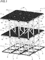
- the three-dimensional structure (1) of the invention comprises unitary modules (2) which are mutually assembled in juxtaposition to form a first level to be placed on the ground, and then superimposed to form the upper levels.
- the three-dimensional structure (1) of the invention comprises bases (3) intended to equip the underside of the unitary modules (2) and intended to be laid on the floor. soil substantially horizontally in the bottom of the dug basin where the three-dimensional structure (1) is to be assembled.
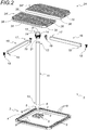
- Such a base (3) is represented in the unitary state on the figure 2 .
- It comprises at least one recess (4) for passing water and is preferably in the form of a generally rectangular frame and preferentially square.
- Each base (3) and also comprises at least one receiving housing (5), preferably only one, in its upper face.
- the receiving housing (5) is provided in a corner of said frame.
- This receiving housing (5) is preferably in the form of a cylindrical housing adapted to receive a vertical tube in its upper part.
- Each base (3) preferably comprises lateral attachment structures, for example clipping or interlocking structures, provided to allow mutual lateral assembly of the bases (3) with each other.
- each base (3) thus comprises hooking ramps on two consecutive lateral faces, while the two other consecutive lateral faces have complementary hooking ramps. provided so that bases (3) located side by side can be mutually assembled and immobilized by the engagement of the hooking ramp of a base (3) with the complementary hooking ramp of the base (3) neighbor.
- each base (3) is preferably equipped with a sole (6) having a lower flat and horizontal support surface mounted under said base (3) and secured thereto.
- the sole (6) is preferably provided at the receiving housing (5) shaped in the base (3).
- the receiving housing (5) preferably has a male piece (7) in its upper part, intended to be introduced into a complementary female part (8) formed in the lower part of the receiving housing (5) to be housed and immobilized.
- the receiving housing (5) is in the form of a cylindrical housing
- the lower part of said housing acts as a female part (8)
- the male part (7) of the sole (6) is preferably in the form of a cylindrical piece.
- the base (3) and the sole (6) are preferably made of injected plastic material and they comprise ribs (9) of reinforcement and stiffening.
- each base (3) is provided for housing and immobilizing the lower end (10) of a vertical tube (11).
- each unit module (2) comprises a single vertical tube (11), preferably of cylindrical shape.
- Each single vertical tube (11) is preferably in the form of a hollow tube with a round section of composite material, for example obtained by pultrusion of continuous glass fibers and resin.
- Each unitary module (2) also includes an end cap (12) adapted to be attached at the top end (13) of the vertical tube (11), the end cap (12) having a top receiver housing (5 ') shaped in its upper part and a lower receiving housing (5 ") shaped in its lower part, these receiving housing (5', 5") being substantially identical in shape to the receiving housing (5) of each base (3) ).
- each base (3) and the upper receiving housing (5 ') of each end fitting (12) are of complementary shape to that of the lower end (10) of the vertical tube (11). to receive the lower end (10) of a vertical tube (11) in a snug fit.
- each end nozzle (12) is of complementary shape to that of the upper end (13) of the vertical tube (11) to be mounted in the upper part of the vertical tube ( 11).
- each end piece (12) is preferably in the form of a cylindrical piece, and its receiving receptacles (5 ', 5 ") as well as the receiving receptacle (5) ) of each base (3) are also preferably cylindrical.
- each end cap (12) has at least two beam mounting bearings (14) which extend radially outwardly from said end cap (12).
- Each end piece (12) preferably comprises four beam mounting bearings (14) evenly distributed in a cross at an angle of 90 ° to each other on the periphery of said end piece (12).
- Each end piece (12) is preferably obtained by plastic injection. It preferably comprises ribs (15) of reinforcement and stiffening. These reinforcing ribs (15) and stiffening are preferably located around each support bearing (14) beam to strengthen them.
- Each unitary module (2) further comprises at least two horizontal beams (16) whose first end (17) is fixed to a beam mounting bearing (14) of the vertical tube (11), while its other end (18) ) is intended to be fixed to a beam mounting bearing (14) of a vertical tube (11) of another adjacent unitary module (2), said beam (16) being positioned horizontally between the two vertical tubes (11). ) thus connected.
- each horizontal beam (16) preferably comprises a beam attachment end (19) secured to each of its ends (17, 18) and adapted to cooperate with a beam mounting bearing (14) of an end piece (12).
- Each horizontal beam (16) thus makes it possible to connect two vertical tubes (11) at their respective end-piece (12) as shown in the drawings.
- Figures 16a and 16b In these figures, each beam mounting bearing (14) has an opening (20) in its upper part, in which is introduced a projecting portion (21) provided in each of the attachment pieces (19) beam.
- Each horizontal beam (16) is preferably in the form of a hollow tube of rectangular section of composite material, for example obtained by pultrusion of continuous glass fibers and resin.
- each beam attachment piece (19) is preferably made of an injected plastics material and has reinforcement and stiffening ribs (22). It has a receiving hollow portion (23) for mounting in tight fit and / or welding on the free end of a beam (16).
- Each unit module (2) finally comprises at least one grid (24) positioned on the horizontal beams (16) located to form a circulation floor.
- the grid (24) is generally rectangular in shape and preferably square. It may be in one piece, or in several parts (24 ', 24 ") juxtaposed
- the grid (24) is preferably made of injected plastic material.
- the grid (24) is preferably in the form of a honeycomb structure designed to pass water and having a planar upper face to serve as a circulation floor for those responsible for assembling the three-dimensional structure (1) of the invention.
- Each grid (24) to include one or more inserts (25) for reinforcement and stiffening, each designed to be introduced into a receiving housing (26) shaped in the body of the grid (24).
- the main role of these inserts (25) is to strengthen the flexural strength of the grids (24).
- each reinforcing and stiffening insert (25) is preferably in the form of a hollow tube of rectangular section of composite material, for example obtained by pultrusion of continuous glass fibers and resin.
- certain unitary modules (2) may also comprise one or more oblique crutches (27) for stiffening. These oblique crutches (27) are preferably provided at the level of the unit modules (2) located at the periphery of the three-dimensional structure (1) to reinforce its mechanical strength, especially with respect to the lateral thrust exerted by the earth mass which surround it when the pit where the three-dimensional structure (1) is filled with earth.
- each oblique stand (27) is preferably in the form of a hollow tube of round section of composite material, for example obtained by pultrusion of continuous glass fibers and resin.
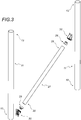
- Each oblique crutch (27) is provided to be fixed in a manner inclined on two vertical tubes (11) to connect and immobilize each other.
- each oblique leg (27) comprises a fixing piece (29) of stand provided to cooperate in fixing and immobilization with a bearing (30) of support provided on each two vertical tubes (11) to be connected.
- An oblique crutch (27) equipped with a fixing piece (29) of crutch at each of its ends (28) is illustrated on the figure 13 .
- Each oblique crutch (27) is preferably symmetrical and its two ends (28) are identical.
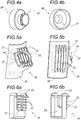
- each attachment piece (29) of stand is preferably made of injected plastic material. It has a receiving hollow portion (31) for mounting in close fit and / or welding on the free end (28) of an oblique stand (27), and a projecting portion (32) to be received immobilized in a receiving member (33) provided in each support bearing (30) of stand, this receiving member (33) preferably have a lateral opening (34) for receiving the projecting portion (32) of a mouthpiece fixing (29) crutch (see Figures 15a and 15b ) and clipping means (37) thereof.
- each support bearing (30) for stand is preferably made of injected plastic material. It has reinforcement and stiffening ribs (35), a receiving part (33) oriented preferably inclined at the same angle of inclination of the oblique legs (27), and a base (36) intended to be secured to the outer periphery.
- the base (36) preferably has a complementary concavity of the external shape of the vertical tube (11).
- a first support bearing (30) of support is preferably provided in the lower part of a first vertical tube (11), while a second support bearing (30) of crutches is preferably provided in the upper half of a second vertical tube (11) adjacent.
- each oblique crutch (27) is preferably approximately 45 °.
- the same vertical tube (11) can be equipped with one or more support bearings (30) of stand as required for the three-dimensional structure (1).
- the gate (24) of the unitary module (2) of the invention is preferably of substantially square shape, with a width and a length of about 1 meter, which provides sufficient mechanical strength for a large area.
- the grid (24) preferably has a width and a length of between 50 centimeters and 150 centimeters.
- each vertical tube (11) of the unitary module (2) of the invention may be variable, as adapted to the height of the buried basin infiltration, retention and / or storage of rainwater provided.
- these tubes can be up to 2 meters high without presenting a risk of excessive bending. They preferably have a length of between 1.5 and 2 meters, and more preferably a height of about 1.6 meters, which allows operators to circulate under the grids (24).
- the three-dimensional structure (1) may comprise a closing geogrid (not shown) which surrounds its periphery and whose mesh is dimensioned so as to prevent the earth from penetrating laterally inside the three-dimensional structure ( 1).
- an engineer or a technician dimensions the three-dimensional structure (1) and determines the number, the position and the orientation of the different oblique stiffening crutches (27) required for the buried basin. infiltration, retention and / or storage of rainwater. It thus provides a specific assembly plan for this three-dimensional structure (1) to the assemblers responsible for assembling the three-dimensional structure (1) on site.
- vertical tubes are equipped bearings (30) for fixing the stand.
- the different end pieces (12, 19, 29) can be pre-mounted on their respective tubular element (11, 16, 27).
- the inserts (25) for reinforcement and stiffening can be introduced at the factory into each grid (24), and the flanges (6) can be mounted on the underside of each base (3).
- the assemblers After transportation and unloading on site of the various means constituting the three-dimensional structure (1), whereas the receiving pit for this three-dimensional structure (1) has already been dug and flattened, the assemblers begin by positioning the bases (3) on the ground, each being preferably equipped with a sole (6). These bases (3) are mutually assembled and immobilized by assembling their hooking ramps and their respective complementary hooking ramps. They then form a kind of flat and water permeable pavement provided in the bottom of the basin which will serve as a base for the unit modules (2) to be assembled on it.
- a vertical tube (11) is then housed and immobilized by its lower end (10) in the receiving housing (5) of each base (3), and an end piece (12) engaged at the upper end. (13) of each vertical tube (11) if this had not been done in the factory (see figure 7 ).
- the assemblers then fix the oblique stiffening legs (27) by clipping between the vertical tubes (11) where necessary.
- Securing by securing an oblique stiffening stand (27) on a vertical tube (11) is represented on the Figures 15a and 15b .
- An oblique stiffening stand (27) immobilized between two vertical tubes (11) is also shown in profile on the Figures 10 and 11 .
- the assemblers also fix the horizontal beams (16), with one beam (16) between each pair of adjacent vertical tubes (11) so as to form a horizontal support frame for the grids (24), this frame being preferentially similar in shape to that of the base (3) located below and located in the same vertical volume.
- Securing by clipping of a beam (16) on the end piece (12) of a vertical tube (11) is represented on the Figures 16a and 16b .
- the grids (24) equipped with inserts (25) are then placed on these frames.
- Each grid (24) is preferably immobilized in wedging between four horizontal beams (16) forming a frame by the support of a groove (38) on the upper edge of the beams (16), this groove (38) being shaped in the lower part of the perimeter of each grid (24) (see figure 8 ).
- the grids (24) of the already assembled unitary modules (2) form a floor on which the assemblers can freely move to assemble the unit modules ( 2) in order to add an additional level of unit modules (2) in height for the three-dimensional structure (1).
- This assembly is very similar to the previous one. The only difference lies in the fact that a vertical tube (11) is not mounted in the receiver housing (5) of the bases (3), but that a vertical tube (11) is housed and immobilized in the receiving housing bottom (5 ") of each end piece (12) of the vertical tubes (11) below.
- the three-dimensional structure (1) according to the invention may comprise several stages.
- the end caps (12) in the upper part of the vertical tubes (11) allow to insert the vertical tubes (11) of the next stage.
- figure 1 illustrates a three-dimensional structure (1) comprising only two levels of unitary modules (2), it may comprise any number, or possibly a single level.
- each unitary module (2) the vertical tube (11), the end piece (12), each beam (16), each grid (24), each fixing bearing (30) crutch and each stiffening stand (27) are preferentially dissociated means, that is to say separate means which are provided to be mutually assembled for mounting the three-dimensional structure (1).
- none of these means is formed in one piece with another of these means.
Abstract
La structure tridimensionnelle (1) est formée de modules unitaires (2) mutuellement assemblés en juxtaposition et/ou superposition, comportant chacun un unique tube vertical (11) au niveau de l'extrémité supérieure duquel est monté un embout d'extrémité (12) pour la réception du tube vertical (11) d'un autre module unitaire (2) situé au-dessus. Cet embout d'extrémité (12) comporte des paliers de fixation de poutrelle pour la fixation de poutrelles (16) horizontales formant un cadre de support pour une grille (24) prévue en partie supérieure de chaque module unitaire (2). Les modules unitaires (2) posés au sol comportent une base (3) servant d'embase d'appui au sol. Chaque tube vertical (11) peut comporter un ou plusieurs paliers de fixation de béquille pour le montage incliné de béquilles obliques (27) de rigidification qui relient chacune le tube vertical (11) de deux modules unitaires (2) adjacents.The three-dimensional structure (1) is formed of unitary modules (2) mutually assembled in juxtaposition and / or superposition, each having a single vertical tube (11) at the upper end of which is mounted an end cap (12) for receiving the vertical tube (11) from another unitary module (2) above. This end cap (12) comprises beam mounting bearings for fixing horizontal beams (16) forming a support frame for a grid (24) provided in the upper part of each unit module (2). The unit modules (2) placed on the ground comprise a base (3) serving as a ground support base. Each vertical tube (11) may comprise one or more stand mounting bearings for the inclined mounting oblique legs (27) of stiffening which each connect the vertical tube (11) of two adjacent unit modules (2).
Description
La présente invention se rapporte à une structure tridimensionnelle prévue pour combler un bassin enterré d'infiltration, de rétention et/ou de stockage des eaux de pluie.The present invention relates to a three-dimensional structure intended to fill a buried basin infiltration, retention and / or storage of rainwater.
L'invention concerne plus particulièrement une telle structure tridimensionnelle formée d'éléments en matière plastique et en matériaux composites qui peuvent être préassemblés en usine ou assemblés sur site.The invention more particularly relates to such a three-dimensional structure formed of plastic elements and composite materials that can be preassembled at the factory or assembled on site.
Lors de la construction d'ouvrages tels que des parkings ou des zones industrielles, certaines réglementations imposent la construction d'un bassin enterré d'infiltration, de rétention et/ou de stockage des eaux de pluie dans le sol où sont prévus lesdits ouvrages.When building structures such as car parks or industrial zones, certain regulations require the construction of an underground basin for infiltration, retention and / or storage of rainwater in the soil where these structures are provided.
Ces bassins sont habituellement sous la forme d'installations alvéolaires prévues dans une fosse creusée sous l'ouvrage et comportant un grand volume vide prévu pour l'infiltration, la rétention et le stockage des eaux de pluie. Ces installations alvéolaires sont suffisamment robustes mécaniquement pour supporter le poids de la masse de terre située au-dessus d'elles ainsi que pour supporter le poids de l'ouvrage qui est prévu en surface.These basins are usually in the form of alveolar facilities provided in a pit dug under the structure and having a large empty volume provided for infiltration, retention and storage of rainwater. These cellular installations are mechanically strong enough to support the weight of the earth mass above them as well as to support the weight of the structure which is provided on the surface.
Le déposant commercialise déjà une structure tridimensionnelle intitulée RAUSIKKO Box prévue pour la rétention et la restitution des eaux de pluie soit par infiltration ou débit limité ou régulé. Cette solution consiste à utiliser des plateformes en matière plastique empilables pour leur transport, et qui sont assemblées entres elles afin de former un volume comportant de nombreux espaces creux. Il s'agit avantageusement d'un système qui peut être mis en oeuvre de façon flexible et pérenne dans toutes les configurations imaginables. Ces modules auto-fixants permettent de répondre à toutes les contraintes de chantier : grande modularité, résistance mécanique élevée et exploitation facilitée du système. Les plateformes connues en matière plastique sont très encombrantes pour leur transport, et ce malgré leur caractère empilable. Le temps de montage nécessaire pour assembler ces plateformes est également peu avantageux.The applicant already markets a three-dimensional structure entitled RAUSIKKO Box intended for the retention and return of rainwater either by infiltration or limited or regulated flow. This solution consists of using plastic platforms stackable for their transport, and which are assembled together to form a volume with many cavities. It is advantageously a system that can be implemented flexibly and perennially in all conceivable configurations. These self-fixing modules make it possible to respond to all site constraints: high modularity, high mechanical strength and easy operation of the system. The known plastic platforms are very bulky for their transport, despite their stackability. The assembly time required to assemble these platforms is also not very advantageous.
Par la demande
L'objet de la présente invention vise par conséquent à pallier les inconvénients de l'art antérieur en proposant une nouvelle structure tridimensionnelle à monter pour combler un bassin de rétention des eaux de pluie.The object of the present invention is therefore to overcome the disadvantages of the prior art by proposing a new three-dimensional structure to be mounted to fill a rainwater retention basin.
Les objets assignés à l'invention sont atteints à l'aide d'une structure tridimensionnelle comprenant des modules unitaires mutuellement assemblés en juxtaposition et/ou superposition afin de former une masse poreuse en vue de constituer un bassin d'infiltration, de rétention et/ou de stockage des eaux de pluie, caractérisée en ce qu'elle comprend des bases destinées à être posées au sol sensiblement horizontalement, une base équipant la partie inférieure de chaque module unitaire prévu pour être posé directement au sol afin de servir d'embase d'appui au sol pour celui-ci, et en ce que chaque module unitaire comporte les moyens dissociés suivants, qui sont prévus pour être assemblés mutuellement pour le montage de la structure tridimensionnelle :
- un unique tube vertical dont l'extrémité inférieure est prévue pour être logée et immobilisée dans la partie supérieure d'un logement récepteur, ce logement récepteur étant :
- soit conformé dans une base d'un module unitaire lorsque celui-ci est destiné à être directement posé au sol,
- soit conformé dans un embout d'extrémité prévu au niveau de l'extrémité supérieure du tube vertical d'un autre module unitaire situé en-dessous lorsque le module unitaire est destiné à être monté au-dessus d'un autre module unitaire ;
- un embout d'extrémité prévu pour être monté sur l'extrémité supérieure du tube vertical et comportant au moins deux paliers de fixation de poutrelle qui s'étendent radialement vers l'extérieur à partir dudit embout d'extrémité ;
- au moins deux poutrelles horizontales dont une première extrémité est fixée à un palier de fixation de poutrelle du tube vertical, tandis que son autre extrémité est destinée à être fixée à un palier de fixation de poutrelle d'un tube vertical d'un autre module unitaire adjacent, ladite poutrelle étant positionnée horizontale entre les deux tubes verticaux ainsi reliés ;
- au moins une grille positionnée sur les au moins deux poutrelles horizontales afin de constituer un plancher de circulation.
- a single vertical tube whose lower end is intended to be housed and immobilized in the upper part of a receiving housing, this receiving housing being:
- is shaped in a base of a unitary module when it is intended to be directly placed on the ground,
- is formed in an end piece provided at the upper end of the vertical tube of another unitary module located below when the unitary module is intended to be mounted above another unitary module;
- an end piece intended to be mounted on the upper end of the vertical tube and having at least two beam mounting bearings which extend radially outwardly from said end cap;
- at least two horizontal beams, one end of which is fixed to a beam fixing bearing of the vertical tube, while its other end is intended to be fixed to a beam fixing bearing of a vertical tube of another unitary module adjacent, said beam being positioned horizontally between the two vertical tubes thus connected;
- at least one grid positioned on the at least two horizontal beams to form a circulation floor.
Selon un exemple de mise en oeuvre de l'invention, chaque module unitaire comporte en outre les moyens dissociés suivants prévus pour être assemblés mutuellement pour le montage de la structure tridimensionnelle :
- au moins un palier de fixation de béquille solidarisé sur le pourtour externe du tube vertical ;
- au moins une béquille oblique de rigidification dont une première extrémité est fixée à un palier de fixation de béquille du tube vertical, tandis que son autre extrémité est destinée à être fixée à un palier de fixation de béquille du tube vertical d'un autre module unitaire adjacent, ladite béquille oblique étant positionnée inclinée entre les deux tubes verticaux ainsi reliés.
- at least one support bearing fixed on the outer periphery of the vertical tube;
- at least one oblique stiffening leg, one end of which is fixed to a support for fixing the stand of the vertical tube, while its other end is intended to be fixed to a support for fixing the stand of the vertical tube of another unitary module adjacent, said oblique crutch being positioned inclined between the two vertical tubes thus connected.
Selon un autre exemple de mise en oeuvre de l'invention, un tube vertical comprend au moins un palier de fixation de béquille au niveau de son extrémité inférieure et/ou au moins un palier de fixation de béquille au niveau de sa moitié supérieure.According to another example of implementation of the invention, a vertical tube comprises at least one bracket for fixing the stand at its lower end and / or at least one bracket fixing bracket at its upper half.
Selon un exemple supplémentaire de mise en oeuvre de l'invention, au moins un palier de fixation de béquille est solidarisé sur un tube vertical par soudage ou par collage.According to a further example of implementation of the invention, at least one support bearing bracket is secured to a vertical tube by welding or gluing.
Selon un autre exemple de mise en oeuvre de l'invention, au moins une béquille oblique de rigidification comporte un embout de fixation de béquille solidarisé à au moins une de ses extrémités et prévu pour coopérer avec une forme réceptrice prévue dans un palier de fixation de béquille.According to another example of implementation of the invention, at least one oblique stiffening leg comprises a bolt fastening end secured to at least one of its ends and adapted to cooperate with a receiving form provided in a fixing bearing. crutch.
Selon un exemple de mise en oeuvre supplémentaire de l'invention, au moins une poutrelle horizontale comporte un embout de fixation de poutrelle solidarisé à au moins une de ses extrémités et prévu pour coopérer avec un palier de fixation de poutrelle d'un embout d'extrémité.According to an additional embodiment of the invention, at least one horizontal beam comprises a beam attachment end secured to at least one of its ends and adapted to cooperate with a beam fixing bearing of an end piece. end.
Selon un exemple de mise en oeuvre de l'invention, la base équipant la partie inférieure de chaque module unitaire prévu pour être posé directement au sol présente un évidement et comporte un logement récepteur dans sa face supérieure.According to an exemplary implementation of the invention, the base equipping the lower part of each unit module intended to be placed directly on the ground has a recess and comprises a receiving housing in its face. higher.
Selon un autre exemple de mise en oeuvre de l'invention, la base équipant la partie inférieure de chaque module unitaire prévu pour être posé directement au sol comporte une semelle présentant une surface inférieure d'appui plane et horizontale montée sous ladite base et solidarisée à celle-ci.According to another example of implementation of the invention, the base equipping the lower part of each unitary module intended to be placed directly on the ground comprises a soleplate having a lower surface flat and horizontal support mounted under said base and secured to it.
Selon un exemple supplémentaire de mise en oeuvre de l'invention, la semelle est prévue au niveau du logement récepteur conformé dans la base destinée à être posée au sol.According to a further example of implementation of the invention, the sole is provided at the receiving housing shaped in the base to be placed on the ground.
Selon un exemple de mise en oeuvre de l'invention, la semelle comporte une pièce mâle dans sa partie supérieure, prévue pour être introduite dans une pièce femelle complémentaire conformée dans la partie inférieure du logement récepteur afin d'y être logée et immobilisée.According to an exemplary implementation of the invention, the sole comprises a male part in its upper part, intended to be introduced into a complementary female part formed in the lower part of the receiving housing to be housed and immobilized.
Selon un autre exemple de mise en oeuvre de l'invention, la base équipant la partie inférieure de chaque module unitaire prévu pour être posé directement au sol est sous la forme d'un cadre de forme générale rectangulaire et préférentiellement carrée.According to another example of implementation of the invention, the base equipping the lower part of each unit module intended to be placed directly on the ground is in the form of a generally rectangular frame and preferably square.
Selon un exemple supplémentaire de mise en oeuvre de l'invention, la base équipant la partie inférieure de chaque module unitaire prévu pour être posé directement au sol comporte des structures de clipsage, des structures d'emboîtement ou tout autre type de structures d'accrochage, ces structures d'accrochage étant prévues pour assembler les bases de deux modules unitaires adjacents lorsqu'elles sont mutuellement associées.According to a further example of implementation of the invention, the base equipping the lower part of each unit module intended to be placed directly on the ground comprises clipping structures, interlocking structures or any other type of attachment structures , these attachment structures being provided for assembling the bases of two adjacent unit modules when they are mutually associated.
Selon un exemple de mise en oeuvre de l'invention, la base équipant la partie inférieure de chaque module unitaire prévu pour être posé directement au sol comporte un unique logement récepteur pour la réception de l'unique tube vertical du module unitaire prévu pour être posé au sol.According to an exemplary implementation of the invention, the base equipping the lower part of each unit module intended to be placed directly on the ground comprises a single receiving housing for receiving the single vertical tube unit module intended to be installed on the ground.
Selon un autre exemple de mise en oeuvre de l'invention, la grille est de forme générale rectangulaire et préférentiellement carrée, et est d'une seule pièce ou en plusieurs parties juxtaposées.According to another example of implementation of the invention, the grid is generally rectangular in shape and preferably square, and is in one piece or in several parts juxtaposed.
Selon un exemple supplémentaire de mise en oeuvre de l'invention, la structure tridimensionnelle comprend au moins un tube vertical, au moins une béquille et/ou au moins une poutrelle en matériau composite, de préférence obtenu(e) par pultrusion de fibres de verre continues et de résine.According to a further example of implementation of the invention, the three-dimensional structure comprises at least one vertical tube, at least one stand and / or at least one beam of composite material, preferably obtained by pultrusion of glass fibers. continuous and resin.
Selon un exemple de mise en oeuvre de l'invention, la structure tridimensionnelle comprend au moins un embout d'extrémité, au moins une base, au moins une semelle, au moins un palier de fixation de béquille, au moins un embout de fixation de poutrelle et/ou au moins une grille en matière plastique injectée.According to an exemplary implementation of the invention, the three-dimensional structure comprises at least one end piece, at least one base, at least one sole, at least one support leg support, at least one attachment end piece. beam and / or at least one plastic grid injected.
Selon un autre exemple de mise en oeuvre de l'invention, chaque embout d'extrémité comporte quatre paliers de fixation de poutrelle régulièrement répartis à un angle de 90° les uns des autres sur le pourtour dudit embout d'extrémité.According to another exemplary embodiment of the invention, each end piece comprises four beam attachment bearings regularly distributed at an angle of 90 ° to each other around the periphery of said end piece.
Les avantages de la présente invention sont particulièrement nombreux.The advantages of the present invention are particularly numerous.
Avec une hauteur d'environ 1m60 pour les tubes verticaux et des dimensions d'environ 1m x 1m pour la base destinée à être posée horizontalement, chaque module unitaire permet d'occuper un très grand volume. En outre, du fait que chaque module unitaire ne comporte qu'un seul tube vertical, pour un même volume ou un même poids à transporter avant assemblage, les modules unitaires de l'invention permettent de créer un bassin enterré d'infiltration bien plus grand que les solutions antérieures.With a height of about 1m60 for vertical tubes and dimensions of about 1m x 1m for the base to be laid horizontally, each unit module can occupy a very large volume. In addition, since each unitary module has only one vertical tube, for the same volume or the same weight to be transported before assembly, the unitary modules of the invention make it possible to create a much larger buried infiltration basin. than previous solutions.
Les modules unitaires de l'invention présentent également bien moins de pièces à assembler que les solutions antérieures pour créer un bassin enterré d'infiltration de volume équivalent.The unit modules of the invention also have far fewer parts to assemble than previous solutions to create a buried infiltration basin of equivalent volume.
Par la fourniture des différents paliers de fixation, l'invention est facile et rapide à assembler.By providing the various mounting bearings, the invention is easy and quick to assemble.
Les béquilles obliques de rigidification permettent notamment de renforcer la solidité globale de la structure tridimensionnelle, notamment dans les parties périphériques de celle-ci ou elle subit une poussée exercée par la masse de terre qui l'entoure. Le fait qu'un module unitaire soit prévu pour pouvoir comporter ou non des béquilles obliques de rigidification permet une grande liberté de conception pour la structure tridimensionnelle, et permet de prévoir des béquilles obliques de rigidification uniquement là où c'est nécessaire au sein de la structure tridimensionnelle.The oblique stiffening crutches make it possible in particular to reinforce the overall strength of the three-dimensional structure, particularly in the peripheral parts thereof or it undergoes a thrust exerted by the mass of earth that surrounds it. The fact that a unitary module is provided to be able to include or not oblique stiffening crutches allows a great freedom of design for the three-dimensional structure, and allows to provide oblique stiffening crutches only where it is necessary within the three-dimensional structure.
Le fait que les béquilles obliques de rigidification et/ou les poutrelles horizontales puissent comporter un embout de fixation prévu pour coopérer avec une forme réceptrice prévue respectivement dans les paliers de fixation de béquille et/ou dans les embouts d'extrémité permet d'assembler les béquilles obliques de rigidification et/ou les poutrelles horizontales avec les tubes verticaux de manière rapide, aisée et sécuritaire.The fact that the oblique stiffening legs and / or the horizontal beams may comprise a fastening tip provided to cooperate with a receiving form provided respectively in the support leg mounting bearings and / or in the end caps makes it possible to assemble the oblique stiffening crutches and / or horizontal beams with vertical tubes in a fast, easy and safe way.
Les tubes, béquilles et poutrelles en matériau composite, de préférence obtenu(e)s par pultrusion de fibres de verre continues et de résine, offrent une très grande résistance mécanique à la structure tridimensionnelle, pour un encombrement, un coût et un poids réduit. Ces éléments tubulaires sont avantageusement légers et ont une très bonne résistance en compression et en flexion.The tubes, crutches and beams of composite material, preferably obtained by pultrusion of continuous glass fibers and resin, offer a very high mechanical strength to the three-dimensional structure, for a space, a cost and a reduced weight. These tubular elements are advantageously light and have a very good resistance in compression and flexion.
De même, les embouts d'extrémité, les bases, les semelles, les paliers, les embouts de fixation et les grilles en matière plastique injectée présentent une résistance mécanique suffisante pour leur rôle, avec un coût et un poids réduit. Des nervures de renfort et de rigidification sont avantageusement prévues pour renforcer la résistance mécanique de ces pièces en plastique injecté.Similarly, the end caps, bases, soles, bearings, end caps and grids injected plastic have sufficient mechanical strength for their role, with reduced cost and weight. Reinforcement and stiffening ribs are advantageously provided to reinforce the mechanical strength of these injected plastic parts.
Malgré leur grande solidité, notamment s'ils sont obtenus par pultrusion de fibres de verre et de résine, les tubes verticaux présentent une certaine flexibilité, ce qui autorise un certain jeu mutuel entre les modules unitaires lors de l'assemblage de la structure tridimensionnelle.Despite their great strength, especially if they are obtained by pultrusion of glass fibers and resin, the vertical tubes have a certain flexibility, which allows some mutual play between the unit modules during the assembly of the three-dimensional structure.
Les structures de clipsage, d'emboîtement ou autres structures d'accrochage des bases permettent de raccorder rapidement et facilement les modules unitaires adjacents qui sont posés au sol, tandis que tous les modules unitaires adjacents sont reliés et solidarisés entre eux par les poutrelles horizontales.Clipping structures, interlocking or other attachment structures of the bases make it possible to quickly and easily connect the adjacent unit modules which are placed on the ground, while all the adjacent unit modules are connected and joined together by the horizontal beams.
Selon un mode de réalisation préféré de l'invention, les moyens constitutifs de chaque module unitaire sont prévus de sorte que chaque module présente une forme générale de parallélépipède, ce qui facilite notamment le montage de la structure tridimensionnelle, et permet de l'étudier et de la concevoir de manière aisée.According to a preferred embodiment of the invention, the constituent means of each unit module are provided so that each module has a general parallelepiped shape, which facilitates in particular the mounting of the three-dimensional structure, and allows to study it and to conceive it easily.
Les grilles permettent avantageusement de circuler sur les modules unitaires inférieurs lors de l'assemblage des modules unitaire supérieurs. Elles laissent passer l'eau et offrent également une certaine rigidité à l'ensemble de la structure tridimensionnelle.The grids advantageously allow to circulate on the lower unit modules during assembly of the upper unit modules. They let in the water and also offer a certain rigidity to the entire three-dimensional structure.
Chaque base permet un appui stable sur le sol pour la structure tridimensionnelle et l'empêche de s'enfoncer dans le sol, cet avantage étant encore accru lorsque les bases sont chacune sous la forme d'un cadre de forme générale rectangulaire et/ou lorsque les bases sont équipées d'une semelle. L'évidement des bases, préférentiellement central, permet de les alléger et de laisser passer l'eau.Each base allows a stable support on the ground for the three-dimensional structure and prevents it from sinking into the ground, this advantage being further increased when the bases are each in the form of a generally rectangular frame and / or when the bases are equipped with a sole. The recess of the bases, preferably central, makes it possible to lighten them and to let the water pass.
D'autres caractéristiques et avantages de la présente invention apparaîtront plus clairement à la lecture de la description qui va suivre, faite en référence aux dessins annexés, donnés à titre d'exemples non limitatifs, dans lesquels :
- la
figure 1 est une vue en perspective d'une structure tridimensionnelle selon l'invention formée de neuf modules unitaires équipés chacun de bases et prévus pour être posés directement au sol, lesquels modules unitaires sont mutuellement assemblés et supportent chacun un autre module unitaire monté au-dessus, pour un total de dix-huit modules unitaires ; - la
figure 2 est une vue en perspective à l'état dissocié d'un module unitaire et d'une base selon l'invention prévus pour être posés directement au sol ; - la
figure 3 est une vue en perspective à l'état dissocié de deux tubes verticaux reliés par une béquille oblique de rigidification au niveau d'un palier de fixation prévu pour être soudé sur chacun des tubes; - les
figures 4a et 4b sont respectivement des vues en perspective trois-quarts de face et de dos d'un embout de fixation de béquille selon l'invention à solidariser au niveau d'une extrémité libre d'une béquille oblique de rigidification ; - les
figures 5a et 5b sont respectivement des vues en perspective trois-quarts de face et de dos d'un palier de fixation de béquille selon l'invention à solidariser sur le pourtour externe d'un tube vertical selon l'invention ; - les
figures 6a et 6b sont respectivement des vues en perspective trois-quarts de face et de dos d'un palier de fixation de poutrelle selon l'invention à solidariser au niveau d'une extrémité libre d'une poutrelle horizontale selon l'invention ; - les
figures 7 à 9 sont des vues en perspective qui illustrent des étapes successives de l'assemblage de modules unitaires selon l'invention ; - la
figure 10 est une vue de profil d'un module unitaire selon l'invention partiellement assemblé; - la
figure 11 est une vue de détail de la partie entouré sur lafigure 10 ; - la
figure 12 est une vue en perspective d'un embout d'extrémité à monter au niveau de l'extrémité supérieure d'un tube vertical selon l'invention ; - la
figure 13 est une vue en perspective d'une béquille oblique de rigidification comportant un embout de fixation de béquille à chacun de ses extrémités, lesdits embouts étant chacun engagé dans une forme réceptrice prévue dans un palier de fixation de béquille ; - la
figure 14 est une vue en perspective d'une poutrelle horizontale comportant un embout de fixation de poutrelle à chacune de ses extrémités ; - la
figure 15a est une vue en perspective illustrant l'assemblage d'une béquille oblique de rigidification équipée d'un embout de fixation de béquille dans une forme réceptrice prévue dans un palier de fixation de béquille soudé sur un tube vertical ; - la
figure 15b est une vue en perspective de la béquille oblique de rigidification selon lafigure 15a fixée au palier de fixation de béquille du tube vertical ; - la
figure 16a est une vue en perspective illustrant l'assemblage d'une poutrelle horizontale équipée d'un embout de fixation de poutrelle dans une forme réceptrice prévue dans un palier de fixation de poutrelle conformé dans un embout d'extrémité ; et - la
figure 16b est une vue en perspective de la poutrelle horizontale selon lafigure 16a fixée à l'embout d'extrémité d'un tube vertical.
- the
figure 1 is a perspective view of a three-dimensional structure according to the invention formed of nine unit modules each equipped with bases and provided to be placed directly on the ground, which unit modules are mutually assembled and each support another unit module mounted above, for a total of eighteen unit modules; - the
figure 2 is a perspective view in the dissociated state of a unitary module and a base according to the invention intended to be placed directly on the ground; - the
figure 3 is a perspective view in the dissociated state of two vertical tubes connected by an oblique stiffening stand at a fixing bearing intended to be welded to each of the tubes; - the
Figures 4a and 4b are respectively three-quarter perspective views of front and back of a stand attachment piece according to the invention to be secured at a free end of an oblique stiffening crutch; - the
Figures 5a and 5b are respectively three-quarter perspective views of the front and back of a stand fixing bracket according to the invention to be secured on the outer periphery of a vertical tube according to the invention; - the
Figures 6a and 6b are respectively three-quarter perspective views of front and back of a beam mounting bearing according to the invention to be secured at a free end of a horizontal beam according to the invention; - the
Figures 7 to 9 are perspective views illustrating successive steps of assembling unit modules according to the invention; - the
figure 10 is a profile view of a unitary module according to the invention partially assembled; - the
figure 11 is a detail view of the part surrounded on thefigure 10 ; - the
figure 12 is a perspective view of an end piece to be mounted at the upper end of a vertical tube according to the invention; - the
figure 13 is a perspective view of an oblique stiffening jack with a jack attachment at each of its ends, said tips being each engaged in a receiving form provided in a support bearing bracket; - the
figure 14 is a perspective view of a horizontal beam having a beam attachment end at each of its ends; - the
figure 15a is a perspective view illustrating the assembly of an oblique stiffening stand equipped with a support leg attachment in a receiving shape provided in a landing bracket bearing welded to a vertical tube; - the
figure 15b is a perspective view of the oblique stiffening stand according to thefigure 15a attached to the landing gear bracket of the vertical tube; - the
figure 16a is a perspective view illustrating the assembly of a beam horizontal beam equipped with a beam attachment end in a receiving shape provided in a beam mounting bearing shaped in an end piece; and - the
figure 16b is a perspective view of the horizontal beam according to thefigure 16a attached to the end cap of a vertical tube.
Les éléments structurellement et fonctionnellement identiques présents sur plusieurs figures distinctes, sont affectés d'une même référence numérique ou alphanumérique.The structurally and functionally identical elements present in several separate figures are assigned a same numerical or alphanumeric reference.
Les localisations supérieures et inférieures des différents moyens constitutifs de l'invention sont données en fonction la position adoptée par ces moyens au sein d'une structure tridimensionnelle assemblée.The upper and lower locations of the various means constituting the invention are given according to the position adopted by these means within an assembled three-dimensional structure.
La structure tridimensionnelle (1) selon l'invention est prévue pour combler un bassin enterré d'infiltration, de rétention et/ou de stockage des eaux de pluie.The three-dimensional structure (1) according to the invention is intended to fill a buried basin infiltration, retention and / or storage of rainwater.
La structure tridimensionnelle (1) de l'invention comprend des modules unitaires (2) qui sont mutuellement assemblés en juxtaposition pour former un premier niveau destiné à être posé au sol, puis superposés afin de former les niveaux supérieurs.The three-dimensional structure (1) of the invention comprises unitary modules (2) which are mutually assembled in juxtaposition to form a first level to be placed on the ground, and then superimposed to form the upper levels.
Pour les modules unitaires (2) qui sont destinés à être posés au sol la structure tridimensionnelle (1) de l'invention comprend des bases (3) prévues pour équiper la face du dessous des modules unitaires (2) et destinées à être posées au sol sensiblement horizontalement dans le fond du bassin creusé où la structure tridimensionnelle (1) doit être assemblée.For the unitary modules (2) which are intended to be placed on the ground, the three-dimensional structure (1) of the invention comprises bases (3) intended to equip the underside of the unitary modules (2) and intended to be laid on the floor. soil substantially horizontally in the bottom of the dug basin where the three-dimensional structure (1) is to be assembled.
Une telle base (3) est représentée à l'état unitaire sur la
Elle comporte au moins un évidement (4) pour laisser passer l'eau et est préférentiellement sous la forme d'un cadre de forme générale rectangulaire et préférentiellement carrée.It comprises at least one recess (4) for passing water and is preferably in the form of a generally rectangular frame and preferentially square.
Chaque base (3) et comporte également au moins un logement récepteur (5), préférentiellement un seul, dans sa face supérieure. Dans le cas préféré où la base (3) est sous la forme d'un cadre, le logement récepteur (5) est prévu dans un coin dudit cadre.Each base (3) and also comprises at least one receiving housing (5), preferably only one, in its upper face. In the preferred case where the base (3) is in the form of a frame, the receiving housing (5) is provided in a corner of said frame.
Ce logement récepteur (5) est préférentiellement sous la forme d'un logement cylindrique prévu pour recevoir un tube vertical dans sa partie supérieure.This receiving housing (5) is preferably in the form of a cylindrical housing adapted to receive a vertical tube in its upper part.
Chaque base (3) comprend préférentiellement des structures latérales d'accrochage, par exemple des structures de clipsage ou d'emboîtement, prévues pour permettre l'assemblage latéral mutuel des bases (3) les unes avec les autres. Selon un mode de réalisation préféré de l'invention, non représenté sur les figures, chaque base (3) comprend ainsi des rampes d'accrochage sur deux faces latérales consécutives, tandis que les deux autres faces latérales consécutives présentent des rampes d'accrochage complémentaires prévues pour que des bases (3) situés côte-à-côte puissent être mutuellement assemblées et immobilisées par l'engagement de la rampe d'accrochage d'une base (3) avec la rampe d'accrochage complémentaire de la base (3) voisine.Each base (3) preferably comprises lateral attachment structures, for example clipping or interlocking structures, provided to allow mutual lateral assembly of the bases (3) with each other. According to a preferred embodiment of the invention, not shown in the figures, each base (3) thus comprises hooking ramps on two consecutive lateral faces, while the two other consecutive lateral faces have complementary hooking ramps. provided so that bases (3) located side by side can be mutually assembled and immobilized by the engagement of the hooking ramp of a base (3) with the complementary hooking ramp of the base (3) neighbor.
Afin d'offrir un meilleur appui au sol pour les modules unitaires (2) qui sont destinés à être posés au sol chaque base (3) est préférentiellement équipée d'une semelle (6) présentant une surface inférieure d'appui plane et horizontale montée sous ladite base (3) et solidarisée à celle-ci.In order to provide better ground support for the unitary modules (2) which are intended to be placed on the ground, each base (3) is preferably equipped with a sole (6) having a lower flat and horizontal support surface mounted under said base (3) and secured thereto.
La semelle (6) est préférentiellement prévue au niveau du logement récepteur (5) conformé dans la base (3).The sole (6) is preferably provided at the receiving housing (5) shaped in the base (3).
Elle présente préférentiellement une pièce mâle (7) dans sa partie supérieure, prévue pour être introduite dans une pièce femelle (8) complémentaire conformée dans la partie inférieure du logement récepteur (5) afin d'y être logée et immobilisée. Lorsque le logement récepteur (5) est sous la forme d'un logement cylindrique, la partie inférieure dudit logement fait office de pièce femelle (8) et la pièce mâle (7) de la semelle (6) est préférentiellement sous la forme d'une pièce cylindrique.It preferably has a male piece (7) in its upper part, intended to be introduced into a complementary female part (8) formed in the lower part of the receiving housing (5) to be housed and immobilized. When the receiving housing (5) is in the form of a cylindrical housing, the lower part of said housing acts as a female part (8) and the male part (7) of the sole (6) is preferably in the form of a cylindrical piece.
La base (3) et la semelle (6) sont préférentiellement fabriquées en matière plastique injectée et elles comportent des nervures (9) de renfort et de rigidification.The base (3) and the sole (6) are preferably made of injected plastic material and they comprise ribs (9) of reinforcement and stiffening.
Le logement récepteur (5) de chaque base (3) est prévu pour loger et immobiliser l'extrémité inférieure (10) d'un tube vertical (11).The receiving housing (5) of each base (3) is provided for housing and immobilizing the lower end (10) of a vertical tube (11).
En effet, chaque module unitaire (2) comprend un unique tube vertical (11), préférentiellement de forme cylindrique.Indeed, each unit module (2) comprises a single vertical tube (11), preferably of cylindrical shape.
Chaque unique tube vertical (11) est de préférence sous la forme d'un tube creux à section ronde en matière composite, par exemple obtenu par pultrusion de fibres de verre continues et de résine.Each single vertical tube (11) is preferably in the form of a hollow tube with a round section of composite material, for example obtained by pultrusion of continuous glass fibers and resin.
Chaque module unitaire (2) comprend également un embout d'extrémité (12) prévu pour être fixé au niveau de l'extrémité supérieure (13) du tube vertical (11), cet embout d'extrémité (12) comportant un logement récepteur supérieur (5') conformé dans sa partie supérieure et un logement récepteur inférieur (5") conformé dans sa partie inférieure, ces logements récepteurs (5', 5") étant de forme sensiblement identique au logement récepteur (5) de chaque base (3).Each unitary module (2) also includes an end cap (12) adapted to be attached at the top end (13) of the vertical tube (11), the end cap (12) having a top receiver housing (5 ') shaped in its upper part and a lower receiving housing (5 ") shaped in its lower part, these receiving housing (5', 5") being substantially identical in shape to the receiving housing (5) of each base (3) ).
Le logement récepteur (5) de chaque base (3) et le logement récepteur supérieur (5') de chaque embout d'extrémité (12) sont de forme complémentaire à celle de l'extrémité inférieure (10) du tube vertical (11) afin de recevoir l'extrémité inférieure (10) d'un tube vertical (11) en ajustement serré.The receiving housing (5) of each base (3) and the upper receiving housing (5 ') of each end fitting (12) are of complementary shape to that of the lower end (10) of the vertical tube (11). to receive the lower end (10) of a vertical tube (11) in a snug fit.
De même, le logement récepteur inférieur (5") de chaque embout d'extrémité (12) est de forme complémentaire à celle de l'extrémité supérieure (13) du tube vertical (11) pour être monté en partie supérieure du tube vertical (11).Similarly, the lower receiver housing (5 ") of each end nozzle (12) is of complementary shape to that of the upper end (13) of the vertical tube (11) to be mounted in the upper part of the vertical tube ( 11).
Ainsi, lorsque chaque tube vertical (11) est de forme cylindrique chaque embout d'extrémité (12) est préférentiellement sous la forme d'une pièce cylindrique, et ses logements récepteurs (5', 5") ainsi que le logement récepteur (5) de chaque base (3) sont également préférentiellement cylindriques.Thus, when each vertical tube (11) is cylindrical in shape, each end piece (12) is preferably in the form of a cylindrical piece, and its receiving receptacles (5 ', 5 ") as well as the receiving receptacle (5) ) of each base (3) are also preferably cylindrical.
En se référant à la
Chaque embout d'extrémité (12) est préférentiellement obtenu par injection de matière plastique. Il comporte de préférence des nervures (15) de renfort et de rigidification. Ces nervures (15) de renfort et de rigidification sont préférentiellement situées autour de chaque palier de fixation (14) de poutrelle afin de les renforcer.Each end piece (12) is preferably obtained by plastic injection. It preferably comprises ribs (15) of reinforcement and stiffening. These reinforcing ribs (15) and stiffening are preferably located around each support bearing (14) beam to strengthen them.
Chaque module unitaire (2) comprend en outre au moins deux poutrelles (16) horizontales dont une première extrémité (17) est fixée à un palier de fixation (14) de poutrelle du tube vertical (11), tandis que son autre extrémité (18) est destinée à être fixée à un palier de fixation (14) de poutrelle d'un tube vertical (11) d'un autre module unitaire (2) adjacent, ladite poutrelle (16) étant positionnée horizontale entre les deux tubes verticaux (11) ainsi reliés.Each unitary module (2) further comprises at least two horizontal beams (16) whose first end (17) is fixed to a beam mounting bearing (14) of the vertical tube (11), while its other end (18) ) is intended to be fixed to a beam mounting bearing (14) of a vertical tube (11) of another adjacent unitary module (2), said beam (16) being positioned horizontally between the two vertical tubes (11). ) thus connected.
En se référant à la
Chaque poutrelle (16) horizontale est de préférence sous la forme d'un tube creux à section rectangulaire en matière composite, par exemple obtenu par pultrusion de fibres de verre continues et de résine.Each horizontal beam (16) is preferably in the form of a hollow tube of rectangular section of composite material, for example obtained by pultrusion of continuous glass fibers and resin.
En se référant aux
Chaque module unitaire (2) comprend enfin au moins une grille (24) positionnée sur les poutrelles (16) horizontales situées afin de constituer un plancher de circulation. La grille (24) est de forme générale rectangulaire et préférentiellement carrée. Elle peut être d'une seule pièce, ou en plusieurs parties (24', 24") juxtaposées. La grille (24) est préférentiellement fabriquée en matière plastique injectée.Each unit module (2) finally comprises at least one grid (24) positioned on the horizontal beams (16) located to form a circulation floor. The grid (24) is generally rectangular in shape and preferably square. It may be in one piece, or in several parts (24 ', 24 ") juxtaposed The grid (24) is preferably made of injected plastic material.
La grille (24) est de préférence sous la forme d'une structure alvéolaire prévue pour laisser passer l'eau et comportant une face supérieure plane afin de servir de plancher de circulation pour les personnes chargées d'assembler la structure tridimensionnelle (1) de l'invention.The grid (24) is preferably in the form of a honeycomb structure designed to pass water and having a planar upper face to serve as a circulation floor for those responsible for assembling the three-dimensional structure (1) of the invention.
Chaque grille (24) pour comporter un ou plusieurs inserts (25) de renfort et de rigidification, prévus pour être introduits chacun dans un logement récepteur (26) conformé dans le corps de la grille (24). Le rôle principal de ces inserts (25) est de renforcer la résistance en flexion des grilles (24).Each grid (24) to include one or more inserts (25) for reinforcement and stiffening, each designed to be introduced into a receiving housing (26) shaped in the body of the grid (24). The main role of these inserts (25) is to strengthen the flexural strength of the grids (24).
En se référant à la
Selon une variante préférée de l'invention certains modules unitaires (2) peuvent aussi comprendre une ou plusieurs béquilles obliques (27) de rigidification. Ces béquilles obliques (27) sont préférentiellement prévues au niveau des modules unitaires (2) situés en périphérie de la structure tridimensionnelle (1) pour renforcer sa résistance mécanique, notamment vis-à-vis de la poussée latérale exercée par la masse de terre qui l'entoure lorsque fosse où se trouve la structure tridimensionnelle (1) est comblée avec de la terre.According to a preferred variant of the invention, certain unitary modules (2) may also comprise one or more oblique crutches (27) for stiffening. These oblique crutches (27) are preferably provided at the level of the unit modules (2) located at the periphery of the three-dimensional structure (1) to reinforce its mechanical strength, especially with respect to the lateral thrust exerted by the earth mass which surround it when the pit where the three-dimensional structure (1) is filled with earth.
En se référant à la
Chaque béquille oblique (27) est prévue pour être fixée de manière inclinée sur deux tubes verticaux (11) afin de les relier et les immobiliser mutuellement.Each oblique crutch (27) is provided to be fixed in a manner inclined on two vertical tubes (11) to connect and immobilize each other.
Dans ce but, au niveau de chacune de ses extrémités (28) chaque béquille oblique (27) comporte un embout de fixation (29) de béquille prévu pour coopérer en fixation et immobilisation avec un palier de fixation (30) de béquille prévu sur chacun des deux tubes verticaux (11) qu'elle doit relier. Une béquille oblique (27) équipée d'un embout de fixation (29) de béquille à chacun de ses extrémités (28) est illustrée sur la
Chaque béquille oblique (27) est préférentiellement symétrique et ses deux extrémités (28) sont identiques.Each oblique crutch (27) is preferably symmetrical and its two ends (28) are identical.
En se référant aux
En se référant aux
Comme cela apparaît sur la
L'angle d'inclinaison de chaque béquille oblique (27) est préférentiellement d'environ 45°.The angle of inclination of each oblique crutch (27) is preferably approximately 45 °.
Un même tube vertical (11) peut être équipé d'aucun ou de plusieurs paliers de fixation (30) de béquille selon les besoins pour la structure tridimensionnelle (1).The same vertical tube (11) can be equipped with one or more support bearings (30) of stand as required for the three-dimensional structure (1).
La grille (24) du module unitaire (2) de l'invention est préférentiellement de forme sensiblement carrée, avec une largeur et une longueur d'environ 1 mètre, ce qui offre une résistance mécanique suffisante pour une grande surface. De manière générale, la grille (24) présente préférentiellement une largeur et une longueur comprises entre 50 centimètres et 150 centimètres.The gate (24) of the unitary module (2) of the invention is preferably of substantially square shape, with a width and a length of about 1 meter, which provides sufficient mechanical strength for a large area. In general, the grid (24) preferably has a width and a length of between 50 centimeters and 150 centimeters.
La hauteur de chaque tube vertical (11) du module unitaire (2) de l'invention peut être variable, car adaptée à la hauteur du bassin enterré d'infiltration, de rétention et/ou de stockage des eaux de pluie prévu. De manière générale, ces tubes peuvent faire jusqu'à 2 mètres de haut sans présenter un risque de flexion excessif. Ils présentent préférentiellement une longueur comprise entre 1,5 et 2 mètres, et plus préférentiellement une hauteur d'environ 1,6 mètre, ce qui permet aux opérateurs de circuler sous les grilles (24).The height of each vertical tube (11) of the unitary module (2) of the invention may be variable, as adapted to the height of the buried basin infiltration, retention and / or storage of rainwater provided. In general, these tubes can be up to 2 meters high without presenting a risk of excessive bending. They preferably have a length of between 1.5 and 2 meters, and more preferably a height of about 1.6 meters, which allows operators to circulate under the grids (24).
Ces dimensions permettent avantageusement de créer une structure tridimensionnelle (1) de grandes dimensions avec peu de modules unitaires (2), pour un coût et un temps de pose réduits, tout en offrant une résistance mécanique suffisante en déformation et en compression pour l'ensemble.These dimensions advantageously make it possible to create a three-dimensional structure (1) of large dimensions with few unitary modules (2), for a reduced cost and installation time, while offering sufficient mechanical strength in deformation and compression for the assembly. .
De manière connue, la structure tridimensionnelle (1) peut comprendre comprend une géogrille de fermeture (non représentée) qui entoure sa périphérie et dont le maillage est dimensionné de sorte d'empêcher la terre de pénétrer latéralement à l'intérieur de la structure tridimensionnelle (1).In known manner, the three-dimensional structure (1) may comprise a closing geogrid (not shown) which surrounds its periphery and whose mesh is dimensioned so as to prevent the earth from penetrating laterally inside the three-dimensional structure ( 1).
En se référant notamment aux
Dans un premier temps, au cours d'un travail préparatoire, un ingénieur ou un technicien dimensionne la structure tridimensionnelle (1) et détermine le nombre, la position et l'orientation des différentes béquilles obliques de rigidification (27) nécessaires pour le bassin enterré d'infiltration, de rétention et/ou de stockage des eaux de pluie. Il fournit ainsi un plan de montage spécifique à cette structure tridimensionnelle (1) aux monteurs chargés d'assembler la structure tridimensionnelle (1) sur site.Firstly, during a preparatory work, an engineer or a technician dimensions the three-dimensional structure (1) and determines the number, the position and the orientation of the different oblique stiffening crutches (27) required for the buried basin. infiltration, retention and / or storage of rainwater. It thus provides a specific assembly plan for this three-dimensional structure (1) to the assemblers responsible for assembling the three-dimensional structure (1) on site.
En usine, en fonction de ces plans, des tubes verticaux sont équipés de paliers de fixation (30) de béquille. Les différents embouts (12, 19, 29) peuvent être pré-montés sur leur élément tubulaire respectif (11, 16, 27). De même, les inserts (25) de renfort et de rigidification peuvent être introduits en usine dans chaque grille (24), et les semelles (6) peuvent être montées en sous-face de chaque base (3).In the factory, according to these plans, vertical tubes are equipped bearings (30) for fixing the stand. The different end pieces (12, 19, 29) can be pre-mounted on their respective tubular element (11, 16, 27). Similarly, the inserts (25) for reinforcement and stiffening can be introduced at the factory into each grid (24), and the flanges (6) can be mounted on the underside of each base (3).
Ces étapes sont préférentiellement réalisées en usine afin de gagner du temps de montage sur site.These steps are preferably performed in the factory in order to save on-site assembly time.
Après transport et déchargement sur site des différents moyens constitutifs de la structure tridimensionnelle (1), alors que la fosse réceptrice pour cette structure tridimensionnelle (1) a déjà été creusée et aplanie, les monteurs commencent par positionner les bases (3) au sol, chacune étant préférentiellement équipée d'une semelle (6). Ces bases (3) sont mutuellement assemblées et immobilisées par assemblage de leurs rampes d'accrochage et de leurs rampes d'accrochage complémentaires respectives. Elles forment alors une sorte de dallage plat et perméable à l'eau prévu dans le fond du bassin qui servira d'embase pour les modules unitaires (2) qui seront assemblés dessus.After transportation and unloading on site of the various means constituting the three-dimensional structure (1), whereas the receiving pit for this three-dimensional structure (1) has already been dug and flattened, the assemblers begin by positioning the bases (3) on the ground, each being preferably equipped with a sole (6). These bases (3) are mutually assembled and immobilized by assembling their hooking ramps and their respective complementary hooking ramps. They then form a kind of flat and water permeable pavement provided in the bottom of the basin which will serve as a base for the unit modules (2) to be assembled on it.
Un tube vertical (11) est alors logé et immobilisé par son extrémité inférieure (10) dans le logement récepteur (5) de chaque base (3), et un embout d'extrémité (12) en engagé au niveau de l'extrémité supérieure (13) de chaque tube vertical (11) si cela n'avait pas été fait préalablement en usine (voir
Les monteurs fixent ensuite les béquilles obliques de rigidification (27) par clipsage entre les tubes verticaux (11) où cela est nécessaire. La sécurisation par clipsage d'une béquille oblique de rigidification (27) sur un tube vertical (11) est représentée sur les
Les monteurs fixent aussi les poutrelles (16) horizontales, à raison d'une poutrelle (16) entre chaque paire de tubes verticaux (11) adjacents de manière à former un cadre horizontal de support pour les grilles (24), ce cadre étant préférentiellement de forme similaire à celui de la base (3) située en dessous et situé dans un même volume vertical. La sécurisation par clipsage d'une poutrelle (16) sur l'embout d'extrémité (12) d'un tube vertical (11) est représentée sur les
Lorsque les modules unitaires (2) qui sont destinés à être posés au sol ont été assemblés, les grilles (24) des modules unitaires (2) déjà assemblés forment un plancher sur lequel les monteurs peuvent librement circuler pour d'assembler les modules unitaires (2) suivant afin d'ajouter un niveau de modules unitaires (2) supplémentaire en hauteur pour la structure tridimensionnelle (1).When the unit modules (2) which are intended to be placed on the ground have been assembled, the grids (24) of the already assembled unitary modules (2) form a floor on which the assemblers can freely move to assemble the unit modules ( 2) in order to add an additional level of unit modules (2) in height for the three-dimensional structure (1).
Cet assemblage est très similaire au précédent. La seule différence réside dans le fait qu'un tube vertical (11) n'est pas monté dans le logement récepteur (5) des bases (3), mais qu'un tube vertical (11) est logé et immobilisé dans le logement récepteur inférieur (5") de chaque embout d'extrémité (12) des tubes verticaux (11) situés en dessous.This assembly is very similar to the previous one. The only difference lies in the fact that a vertical tube (11) is not mounted in the receiver housing (5) of the bases (3), but that a vertical tube (11) is housed and immobilized in the receiving housing bottom (5 ") of each end piece (12) of the vertical tubes (11) below.
La structure tridimensionnelle (1) selon l'invention peut comporter plusieurs étages. Les embouts d'extrémité (12) en partie supérieur des tubes verticaux (11) permettent d'insérer les tubes verticaux (11) de l'étage suivant.The three-dimensional structure (1) according to the invention may comprise several stages. The end caps (12) in the upper part of the vertical tubes (11) allow to insert the vertical tubes (11) of the next stage.
Ainsi, bien que la
Afin d'adapter la hauteur de la structure tridimensionnelle (1), avantageusement seule la hauteur des tubes verticaux (11) doit être adaptée en conséquence.In order to adapt the height of the three-dimensional structure (1), advantageously only the height of the vertical tubes (11) must be adapted accordingly.
Une fois la structure tridimensionnelle (1) assemblée, sa conformité au plan de montage spécifique peut être vérifiée et validée avant qu'une géogrille de fermeture (non représentée) soit mise en place sur sa périphérie.Once the three-dimensional structure (1) assembled, its compliance with the specific assembly plan can be verified and validated before a closing geogrid (not shown) is placed on its periphery.
On notera qu'au sein de chaque module unitaire (2), le tube vertical (11), l'embout d'extrémité (12), chaque poutrelle (16), chaque grille (24), chaque palier de fixation (30) de béquille et chaque béquille oblique (27) de rigidification sont des moyens préférentiellement dissociés, c'est-à-dire des moyens distincts qui sont prévus pour être mutuellement assemblés pour le montage de la structure tridimensionnelle (1). Ainsi, préférentiellement, aucun de ces moyens n'est conformé d'une seule pièce avec un autre de ces moyens.It will be noted that within each unitary module (2), the vertical tube (11), the end piece (12), each beam (16), each grid (24), each fixing bearing (30) crutch and each stiffening stand (27) are preferentially dissociated means, that is to say separate means which are provided to be mutually assembled for mounting the three-dimensional structure (1). Thus, preferably, none of these means is formed in one piece with another of these means.
Il est évident que la présente description ne se limite pas aux exemples explicitement décrits, mais comprend également d'autres modes de réalisation et/ou de mise en oeuvre. Ainsi, une caractéristique technique décrite peut être remplacée par une caractéristique technique équivalente sans sortir du cadre de la présente invention tel que défini par les revendications annexées et une étape décrite de mise en oeuvre du procédé peut être remplacée par une étape équivalente sans sortir du cadre de l'invention tel que défini par les revendications.It is obvious that the present description is not limited to the examples explicitly described, but also includes other embodiments and / or implementation. Thus, a described technical feature may be replaced by an equivalent technical characteristic without departing from the scope of the present invention as defined by the appended claims and a described step of implementation of the method may be replaced by an equivalent step without departing from the scope of the invention as defined by the claims.
Claims (17)
Applications Claiming Priority (1)
| Application Number | Priority Date | Filing Date | Title |
|---|---|---|---|
| FR1853801A FR3080867B1 (en) | 2018-05-03 | 2018-05-03 | THREE-DIMENSIONAL STRUCTURE TO BE MOUNTED TO FILL AN UNDERGROUND RAINWATER RETENTION BASIN |
Publications (1)
| Publication Number | Publication Date |
|---|---|
| EP3564452A1 true EP3564452A1 (en) | 2019-11-06 |
Family
ID=62751148
Family Applications (1)
| Application Number | Title | Priority Date | Filing Date |
|---|---|---|---|
| EP19164875.7A Withdrawn EP3564452A1 (en) | 2018-05-03 | 2019-03-25 | Three-dimensional structure for installation for filling an underground pool for retaining rainwater |
Country Status (2)
| Country | Link |
|---|---|
| EP (1) | EP3564452A1 (en) |
| FR (1) | FR3080867B1 (en) |
Citations (8)
| Publication number | Priority date | Publication date | Assignee | Title |
|---|---|---|---|---|
| JPH10195937A (en) * | 1996-12-28 | 1998-07-28 | Takiron Co Ltd | Filling member for underground water storage tank, and the like |
| JP2003278193A (en) * | 2002-03-22 | 2003-10-02 | Takiron Co Ltd | Underground water storage tank |
| WO2006038602A1 (en) * | 2004-10-04 | 2006-04-13 | Toyo Tire & Rubber Co., Ltd. | Member for rainwater containing structure and rainwater containing structure body using the same |
| WO2011017766A1 (en) * | 2009-08-14 | 2011-02-17 | Gooden, Rebecca | A modulated structural cell for supporting a tree root network |
| KR20110078111A (en) * | 2009-12-30 | 2011-07-07 | 주식회사 한설그린 | Assembling rainwater - storage - block having function of water purification |
| US20130152499A1 (en) * | 2011-12-19 | 2013-06-20 | John E. Kriekemeier | Water retention/detention structure formed from identical panels |
| WO2014161039A1 (en) * | 2013-04-04 | 2014-10-09 | Strata Innovations Pty Limited | A modular cell and matrix for supporting a load bearing feature |
| WO2017217846A1 (en) * | 2016-06-17 | 2017-12-21 | Pipelife Nederland B.V. | Interlocking panels for drainage structures |
-
2018
- 2018-05-03 FR FR1853801A patent/FR3080867B1/en active Active
-
2019
- 2019-03-25 EP EP19164875.7A patent/EP3564452A1/en not_active Withdrawn
Patent Citations (8)
| Publication number | Priority date | Publication date | Assignee | Title |
|---|---|---|---|---|
| JPH10195937A (en) * | 1996-12-28 | 1998-07-28 | Takiron Co Ltd | Filling member for underground water storage tank, and the like |
| JP2003278193A (en) * | 2002-03-22 | 2003-10-02 | Takiron Co Ltd | Underground water storage tank |
| WO2006038602A1 (en) * | 2004-10-04 | 2006-04-13 | Toyo Tire & Rubber Co., Ltd. | Member for rainwater containing structure and rainwater containing structure body using the same |
| WO2011017766A1 (en) * | 2009-08-14 | 2011-02-17 | Gooden, Rebecca | A modulated structural cell for supporting a tree root network |
| KR20110078111A (en) * | 2009-12-30 | 2011-07-07 | 주식회사 한설그린 | Assembling rainwater - storage - block having function of water purification |
| US20130152499A1 (en) * | 2011-12-19 | 2013-06-20 | John E. Kriekemeier | Water retention/detention structure formed from identical panels |
| WO2014161039A1 (en) * | 2013-04-04 | 2014-10-09 | Strata Innovations Pty Limited | A modular cell and matrix for supporting a load bearing feature |
| WO2017217846A1 (en) * | 2016-06-17 | 2017-12-21 | Pipelife Nederland B.V. | Interlocking panels for drainage structures |
Also Published As
| Publication number | Publication date |
|---|---|
| FR3080867A1 (en) | 2019-11-08 |
| FR3080867B1 (en) | 2020-10-23 |
Similar Documents
| Publication | Publication Date | Title |
|---|---|---|
| FR3058432B1 (en) | IMPROVEMENT TO SHOOTING TOWERS. | |
| CA1287724C (en) | Modular building system for wide section covered structure, and related construction process | |
| EP1112425B1 (en) | Method and device for assembling components for water retention tanks, such as swimming pools for example | |
| EP3564452A1 (en) | Three-dimensional structure for installation for filling an underground pool for retaining rainwater | |
| FR2668029A3 (en) | Device for covering over ditches in which trees are planted in thoroughfares | |
| FR2743832A1 (en) | Reinforced concrete posts for building support structure | |
| FR2760482A1 (en) | Shuttering for the formation of concrete slabs or floors using a modular, load bearing system | |
| EP3351706B1 (en) | Swimming pool structure | |
| EP1371785B1 (en) | Prefabricated element for manhole and manhole | |
| WO2015186103A1 (en) | Metal structure for a building and building, for example intended for livestock farming, provided with such a structure | |
| EP3619379A1 (en) | Set of structural elements intended for forming a multi-storey above-ground car park, and corresponding multi-storey above-ground car park | |
| EP1705314A2 (en) | Shelter with support structure made from profiled elements | |
| EP1705317A2 (en) | Shelter with support structure made from profiled elements | |
| FR3080868A1 (en) | THREE-DIMENSIONAL UNITARY ELEMENT FOR FILLING A BOWL BIRD OF RETENTION OF RAIN WATER | |
| FR2900672A1 (en) | Dwelling module for forming e.g. prefabricated single-family house, has base constituted of reinforced concrete slab, where slab has lower surface including connection beams extending from one side to another side of retaining beam | |
| FR2735806A1 (en) | Formwork to support walls of swimming pools | |
| FR2565278A1 (en) | ASSEMBLY OF BUILDING ELEMENTS FOR POST-STRENGTH WALL BUILDING | |
| FR2743100A1 (en) | Retaining/storage wall for bulk product | |
| FR2746124A1 (en) | Structural system e.g. for foundation near growing tree roots | |
| WO2004079131A1 (en) | Panel for civil engineering works, particularly swimming pools, and construction method using such panels | |
| CH694702A5 (en) | Modular construction with at least four vertical posts and braces. | |
| FR2648197A1 (en) | Device for joining wooden elements together to produce a modifiable structure such as, in particular, a shelter against the weather | |
| EP0005575A1 (en) | Prefabricated chimney | |
| FR3133400A1 (en) | ABOVE GROUND POOL STRUCTURE AND ITS ASSEMBLY METHOD | |
| FR2689167A1 (en) | Prefabricated modules intended in particular for constructions exposed to abnormal external conditions, assembly process and constructions obtained. |
Legal Events
| Date | Code | Title | Description |
|---|---|---|---|
| PUAI | Public reference made under article 153(3) epc to a published international application that has entered the european phase |
Free format text: ORIGINAL CODE: 0009012 |
|
| AK | Designated contracting states |
Kind code of ref document: A1 Designated state(s): AL AT BE BG CH CY CZ DE DK EE ES FI FR GB GR HR HU IE IS IT LI LT LU LV MC MK MT NL NO PL PT RO RS SE SI SK SM TR |
|
| AX | Request for extension of the european patent |
Extension state: BA ME |
|
| STAA | Information on the status of an ep patent application or granted ep patent |
Free format text: STATUS: THE APPLICATION IS DEEMED TO BE WITHDRAWN |
|
| 18D | Application deemed to be withdrawn |
Effective date: 20200603 |