EP3564189A1 - Method for preparing nitrogen-doped titanium dioxide and air treatment method - Google Patents
Method for preparing nitrogen-doped titanium dioxide and air treatment method Download PDFInfo
- Publication number
- EP3564189A1 EP3564189A1 EP19172141.4A EP19172141A EP3564189A1 EP 3564189 A1 EP3564189 A1 EP 3564189A1 EP 19172141 A EP19172141 A EP 19172141A EP 3564189 A1 EP3564189 A1 EP 3564189A1
- Authority
- EP
- European Patent Office
- Prior art keywords
- particles
- gas
- titanium dioxide
- nitrogen
- fluidized bed
- Prior art date
- Legal status (The legal status is an assumption and is not a legal conclusion. Google has not performed a legal analysis and makes no representation as to the accuracy of the status listed.)
- Pending
Links
Images



Classifications
-
- B—PERFORMING OPERATIONS; TRANSPORTING
- B01—PHYSICAL OR CHEMICAL PROCESSES OR APPARATUS IN GENERAL
- B01J—CHEMICAL OR PHYSICAL PROCESSES, e.g. CATALYSIS OR COLLOID CHEMISTRY; THEIR RELEVANT APPARATUS
- B01J21/00—Catalysts comprising the elements, oxides, or hydroxides of magnesium, boron, aluminium, carbon, silicon, titanium, zirconium, or hafnium
- B01J21/06—Silicon, titanium, zirconium or hafnium; Oxides or hydroxides thereof
- B01J21/063—Titanium; Oxides or hydroxides thereof
-
- C—CHEMISTRY; METALLURGY
- C01—INORGANIC CHEMISTRY
- C01G—COMPOUNDS CONTAINING METALS NOT COVERED BY SUBCLASSES C01D OR C01F
- C01G23/00—Compounds of titanium
- C01G23/04—Oxides; Hydroxides
- C01G23/047—Titanium dioxide
- C01G23/08—Drying; Calcining ; After treatment of titanium oxide
-
- A—HUMAN NECESSITIES
- A61—MEDICAL OR VETERINARY SCIENCE; HYGIENE
- A61L—METHODS OR APPARATUS FOR STERILISING MATERIALS OR OBJECTS IN GENERAL; DISINFECTION, STERILISATION OR DEODORISATION OF AIR; CHEMICAL ASPECTS OF BANDAGES, DRESSINGS, ABSORBENT PADS OR SURGICAL ARTICLES; MATERIALS FOR BANDAGES, DRESSINGS, ABSORBENT PADS OR SURGICAL ARTICLES
- A61L9/00—Disinfection, sterilisation or deodorisation of air
- A61L9/16—Disinfection, sterilisation or deodorisation of air using physical phenomena
- A61L9/18—Radiation
- A61L9/20—Ultraviolet radiation
- A61L9/205—Ultraviolet radiation using a photocatalyst or photosensitiser
-
- B—PERFORMING OPERATIONS; TRANSPORTING
- B01—PHYSICAL OR CHEMICAL PROCESSES OR APPARATUS IN GENERAL
- B01D—SEPARATION
- B01D53/00—Separation of gases or vapours; Recovering vapours of volatile solvents from gases; Chemical or biological purification of waste gases, e.g. engine exhaust gases, smoke, fumes, flue gases, aerosols
- B01D53/007—Separation of gases or vapours; Recovering vapours of volatile solvents from gases; Chemical or biological purification of waste gases, e.g. engine exhaust gases, smoke, fumes, flue gases, aerosols by irradiation
-
- B—PERFORMING OPERATIONS; TRANSPORTING
- B01—PHYSICAL OR CHEMICAL PROCESSES OR APPARATUS IN GENERAL
- B01D—SEPARATION
- B01D53/00—Separation of gases or vapours; Recovering vapours of volatile solvents from gases; Chemical or biological purification of waste gases, e.g. engine exhaust gases, smoke, fumes, flue gases, aerosols
- B01D53/34—Chemical or biological purification of waste gases
- B01D53/74—General processes for purification of waste gases; Apparatus or devices specially adapted therefor
- B01D53/86—Catalytic processes
- B01D53/8678—Removing components of undefined structure
- B01D53/8687—Organic components
-
- B—PERFORMING OPERATIONS; TRANSPORTING
- B01—PHYSICAL OR CHEMICAL PROCESSES OR APPARATUS IN GENERAL
- B01J—CHEMICAL OR PHYSICAL PROCESSES, e.g. CATALYSIS OR COLLOID CHEMISTRY; THEIR RELEVANT APPARATUS
- B01J27/00—Catalysts comprising the elements or compounds of halogens, sulfur, selenium, tellurium, phosphorus or nitrogen; Catalysts comprising carbon compounds
- B01J27/24—Nitrogen compounds
-
- B—PERFORMING OPERATIONS; TRANSPORTING
- B01—PHYSICAL OR CHEMICAL PROCESSES OR APPARATUS IN GENERAL
- B01J—CHEMICAL OR PHYSICAL PROCESSES, e.g. CATALYSIS OR COLLOID CHEMISTRY; THEIR RELEVANT APPARATUS
- B01J35/00—Catalysts, in general, characterised by their form or physical properties
- B01J35/30—Catalysts, in general, characterised by their form or physical properties characterised by their physical properties
- B01J35/39—Photocatalytic properties
-
- B—PERFORMING OPERATIONS; TRANSPORTING
- B01—PHYSICAL OR CHEMICAL PROCESSES OR APPARATUS IN GENERAL
- B01J—CHEMICAL OR PHYSICAL PROCESSES, e.g. CATALYSIS OR COLLOID CHEMISTRY; THEIR RELEVANT APPARATUS
- B01J37/00—Processes, in general, for preparing catalysts; Processes, in general, for activation of catalysts
- B01J37/02—Impregnation, coating or precipitation
- B01J37/0201—Impregnation
- B01J37/0209—Impregnation involving a reaction between the support and a fluid
-
- B—PERFORMING OPERATIONS; TRANSPORTING
- B01—PHYSICAL OR CHEMICAL PROCESSES OR APPARATUS IN GENERAL
- B01J—CHEMICAL OR PHYSICAL PROCESSES, e.g. CATALYSIS OR COLLOID CHEMISTRY; THEIR RELEVANT APPARATUS
- B01J8/00—Chemical or physical processes in general, conducted in the presence of fluids and solid particles; Apparatus for such processes
- B01J8/18—Chemical or physical processes in general, conducted in the presence of fluids and solid particles; Apparatus for such processes with fluidised particles
- B01J8/1818—Feeding of the fluidising gas
- B01J8/1827—Feeding of the fluidising gas the fluidising gas being a reactant
-
- A—HUMAN NECESSITIES
- A61—MEDICAL OR VETERINARY SCIENCE; HYGIENE
- A61L—METHODS OR APPARATUS FOR STERILISING MATERIALS OR OBJECTS IN GENERAL; DISINFECTION, STERILISATION OR DEODORISATION OF AIR; CHEMICAL ASPECTS OF BANDAGES, DRESSINGS, ABSORBENT PADS OR SURGICAL ARTICLES; MATERIALS FOR BANDAGES, DRESSINGS, ABSORBENT PADS OR SURGICAL ARTICLES
- A61L2209/00—Aspects relating to disinfection, sterilisation or deodorisation of air
- A61L2209/10—Apparatus features
- A61L2209/14—Filtering means
-
- A—HUMAN NECESSITIES
- A61—MEDICAL OR VETERINARY SCIENCE; HYGIENE
- A61L—METHODS OR APPARATUS FOR STERILISING MATERIALS OR OBJECTS IN GENERAL; DISINFECTION, STERILISATION OR DEODORISATION OF AIR; CHEMICAL ASPECTS OF BANDAGES, DRESSINGS, ABSORBENT PADS OR SURGICAL ARTICLES; MATERIALS FOR BANDAGES, DRESSINGS, ABSORBENT PADS OR SURGICAL ARTICLES
- A61L2209/00—Aspects relating to disinfection, sterilisation or deodorisation of air
- A61L2209/10—Apparatus features
- A61L2209/16—Connections to a HVAC unit
-
- B—PERFORMING OPERATIONS; TRANSPORTING
- B01—PHYSICAL OR CHEMICAL PROCESSES OR APPARATUS IN GENERAL
- B01D—SEPARATION
- B01D2255/00—Catalysts
- B01D2255/20—Metals or compounds thereof
- B01D2255/207—Transition metals
- B01D2255/20707—Titanium
-
- B—PERFORMING OPERATIONS; TRANSPORTING
- B01—PHYSICAL OR CHEMICAL PROCESSES OR APPARATUS IN GENERAL
- B01D—SEPARATION
- B01D2255/00—Catalysts
- B01D2255/70—Non-metallic catalysts, additives or dopants
- B01D2255/707—Additives or dopants
-
- B—PERFORMING OPERATIONS; TRANSPORTING
- B01—PHYSICAL OR CHEMICAL PROCESSES OR APPARATUS IN GENERAL
- B01D—SEPARATION
- B01D2255/00—Catalysts
- B01D2255/80—Type of catalytic reaction
- B01D2255/802—Photocatalytic
-
- B—PERFORMING OPERATIONS; TRANSPORTING
- B01—PHYSICAL OR CHEMICAL PROCESSES OR APPARATUS IN GENERAL
- B01D—SEPARATION
- B01D2255/00—Catalysts
- B01D2255/90—Physical characteristics of catalysts
- B01D2255/906—Catalyst dispersed in the gas
-
- B—PERFORMING OPERATIONS; TRANSPORTING
- B01—PHYSICAL OR CHEMICAL PROCESSES OR APPARATUS IN GENERAL
- B01D—SEPARATION
- B01D2258/00—Sources of waste gases
- B01D2258/06—Polluted air
-
- B—PERFORMING OPERATIONS; TRANSPORTING
- B01—PHYSICAL OR CHEMICAL PROCESSES OR APPARATUS IN GENERAL
- B01J—CHEMICAL OR PHYSICAL PROCESSES, e.g. CATALYSIS OR COLLOID CHEMISTRY; THEIR RELEVANT APPARATUS
- B01J2235/00—Indexing scheme associated with group B01J35/00, related to the analysis techniques used to determine the catalysts form or properties
-
- B—PERFORMING OPERATIONS; TRANSPORTING
- B01—PHYSICAL OR CHEMICAL PROCESSES OR APPARATUS IN GENERAL
- B01J—CHEMICAL OR PHYSICAL PROCESSES, e.g. CATALYSIS OR COLLOID CHEMISTRY; THEIR RELEVANT APPARATUS
- B01J35/00—Catalysts, in general, characterised by their form or physical properties
- B01J35/50—Catalysts, in general, characterised by their form or physical properties characterised by their shape or configuration
-
- C—CHEMISTRY; METALLURGY
- C01—INORGANIC CHEMISTRY
- C01P—INDEXING SCHEME RELATING TO STRUCTURAL AND PHYSICAL ASPECTS OF SOLID INORGANIC COMPOUNDS
- C01P2002/00—Crystal-structural characteristics
- C01P2002/50—Solid solutions
- C01P2002/52—Solid solutions containing elements as dopants
- C01P2002/54—Solid solutions containing elements as dopants one element only
-
- C—CHEMISTRY; METALLURGY
- C01—INORGANIC CHEMISTRY
- C01P—INDEXING SCHEME RELATING TO STRUCTURAL AND PHYSICAL ASPECTS OF SOLID INORGANIC COMPOUNDS
- C01P2004/00—Particle morphology
- C01P2004/60—Particles characterised by their size
- C01P2004/61—Micrometer sized, i.e. from 1-100 micrometer
-
- C—CHEMISTRY; METALLURGY
- C01—INORGANIC CHEMISTRY
- C01P—INDEXING SCHEME RELATING TO STRUCTURAL AND PHYSICAL ASPECTS OF SOLID INORGANIC COMPOUNDS
- C01P2004/00—Particle morphology
- C01P2004/60—Particles characterised by their size
- C01P2004/62—Submicrometer sized, i.e. from 0.1-1 micrometer
Definitions
- This disclosure relates to air treatment, and in particular to photocatalytic materials for air treatment.
- Conditioned spaces such as building interiors and aircraft cabins can utilize air purification systems to remove airborne substances such as benzene, formaldehyde, and other contaminants from the air supply.
- Some of these purification systems include photocatalytic reactors that utilize a substrate or cartridge containing a photocatalyst oxide. When placed under an appropriate light source, typically a UV light source, the photocatalyst oxide interacts with airborne water molecules to form hydroxyl radicals or other active species. The hydroxyl radicals react with the contaminants and initiate an oxidation reaction that converts the contaminants into less harmful compounds, such as water and carbon dioxide.
- An air treatment method is disclosed. According to the method, a gas comprising hydrogen and nitrogen, or comprising hydrogen and ammonia, or comprising hydrogen, nitrogen, and ammonia, is introduced to a fluidized bed.
- the gas flows through the fluidized bed, and particles comprising titanium dioxide are introduced to the fluidized bed to form a fluid mixture of the particles and gas in the fluidized bed.
- the particles are reacted with the gas in the fluid mixture to form particles comprising titanium dioxide and nitrogen.
- the particles comprising titanium dioxide and nitrogen are disposed along an air flow path in operative communication with a light source. The light source is activated and the particles are contacted with air to be treated.
- the air to be treated is onboard an aircraft, and contacting the particles with the air to be treated comprises compressing outside low pressure air and contacting the compressed air with the particles.
- the method further includes delivering the air that has contacted the particles or is to be treated to a conditioned interior airspace, e.g. onboard an aircraft.
- a method of making nitrogen-doped titanium dioxide (e.g. for use in the air treatment method, system or device disclosed herein) is disclosed.
- a gas comprising hydrogen and nitrogen, or comprising hydrogen and ammonia, or comprising hydrogen, nitrogen, and ammonia is introduced to a fluidized bed.
- the gas flows through the fluidized bed and through particles comprising titanium dioxide to form a fluid mixture of the particles and gas in the fluidized bed.
- the particles are reacted with the gas in the fluid mixture to form particles comprising titanium dioxide and nitrogen.
- a system for making nitrogen-doped titanium dioxide includes a gas source comprising hydrogen and nitrogen, or comprising hydrogen and ammonia, or comprising hydrogen, nitrogen, and ammonia; a source of titanium dioxide particles; and a fluidized bed arranged to receive gas from the gas source and titanium dioxide particles from the source of titanium dioxide particles and form a fluid mixture of the particles in the gas.
- the gas may include nitrogen and/or ammonia.
- the air treatment system or device includes an air source and a catalytic reactor.
- the catalytic reactor comprises an inlet in operative fluid communication with the air source, an outlet, catalyst particles comprising titanium dioxide and nitrogen made by the above-described method disposed on a fluid flow path between the inlet and the outlet, and a light source in operative communication with the catalyst particles.
- a method of making an air treatment device (e.g. as disclosed herein) is disclosed.
- a gas comprising hydrogen and nitrogen, or comprising hydrogen and ammonia, or comprising hydrogen, nitrogen, and ammonia is introduced to a fluidized bed.
- the gas flows through the fluidized bed, and particles comprising titanium dioxide are introduced to the fluidized bed to form a fluid mixture of the particles and gas in the fluidized bed.
- the particles are reacted with the gas in the fluid mixture to form particles comprising titanium dioxide and nitrogen.
- the particles comprising titanium dioxide and nitrogen are disposed along an air flow path in operative communication with a light source.
- the gas can comprise hydrogen and nitrogen.
- the gas can comprise hydrogen and ammonia.
- the gas can comprise hydrogen, nitrogen, and ammonia.
- the particles can have a diameter of 100 nm to 50 ⁇ m.
- the titanium dioxide can comprise at least 99 wt.% anatase titanium dioxide.
- the titanium dioxide can comprise anatase and rutile titanium dioxide with an anatase:rutile weight ratio of 99:1 to 1:99.
- the titanium dioxide can comprise anatase and rutile titanium dioxide with an anatase:rutile weight ratio of 90:10 to 10:90.
- the method can include flowing the gas through the fluidized bed at a velocity of 6 x 10 -8 m/s to 0.2 m/s.
- the method can include introducing the gas to an outer chamber of the fluidized bed, flowing the gas to an inner chamber positioned within the outer chamber, and introducing the particles comprising titanium dioxide to the inner chamber to form the fluid mixture of the particles and the gas in the inner chamber.
- FIG. 1 An exemplary fluidized bed assembly for treating titanium dioxide particles is shown in FIG. 1 .
- the assembly includes a fluidized bed 12 having inlet openings 14 disposed at one end of the fluidized bed 12 and an outlet opening 16 disposed at the opposite end of the fluidized bed 12.
- the fluidized bed 12 is disposed inside of an outer tubing 18, with outlet 16 extending to the outside of outer tubing 18.
- the fluidized bed assembly is disposed in a furnace (not shown) to provide heat.
- Thermocouples 17 and 19 are disposed to monitor temperature in the fluidized bed 12 and outer tubing 18, respectively.
- An inlet 20 is connected to a gas feed line 22.
- a gas source 24 such as a storage tank or a gas-generating reactor is connected to gas feed line 22 to supply a gas feed to the fluidized bed 12.
- Other components such as mass flow controller 26, pressure regulating valve 28, pressure sensor 30, and shut-off valves 32 and 34 are also disposed in the gas feed line 22 for monitoring and controlling the flow rate and pressure of the gas delivered to the fluidized bed 12.
- Fluidized bed outlet 16 is connected to outlet line 36 that includes a check valve 37, and is connected to a water or other liquid bubbler 38.
- a bleed line 40 with shut-off valve 42 also connects feed line 22 to the bubbler 38, which is vented to atmosphere through exhaust port 44.
- a gas mixture comprising nitrogen and hydrogen, or a gas comprising ammonia and hydrogen, or a gas comprising nitrogen, hydrogen, and ammonia, or a gas of pure ammonia or consisting essentially of ammonia, from gas source(s) 24 is fed through feed line 22, with the flow rate and gas pressure controlled by mass flow controller 26 and pressure regulating valve 28.
- the gas comprises an amount of hydrogen in a range having a low end of 5 mol%, or 10 mol%, or 30 mol%, or 40 mol%, or 60 mol%, and an upper end of 90 mol%, or 80 mol%, or 85 mol%, or 90 mol%, or 95 mol%, based on the total mole percentage of nitrogen, hydrogen, and/or ammonia, in the gas.
- This approach can also be taken with NH 3 / H 2 mixtures which can also be used in controlled nitriding processes. Therefore, this technique can be applied with NH 3 concentrations ranging from 5 - 95% and respective H 2 concentrations between 95 and 5%.
- the above upper and lower range endpoints can be independently combined to disclose a variety of different ranges, and each possible combination of endpoints to form a range is hereby expressly disclosed.
- Other gases e.g., helium, argon
- the gas can in some embodiments comprise an amount of nitrogen in a range having a low end of 5 mol%, or 10 mol%, or 15 mol%, or 20 mol%, and an upper end of 40 mol%, or 60 mol%, or 70 mol%, based on the total moles of gas.
- the above upper and lower range endpoints can be independently combined to disclose a variety of different ranges, and each possible combination of endpoints to form a range is hereby expressly disclosed.
- the nitrogen- and hydrogen-containing gas enters the furnace 18 through inlet 20.
- the gas can be heated, for example, as it passes through the space between fluidized bed 12 and outer tubing 18 to enter the fluidized bed 12 through inlet 14.
- the fluidized bed 12 has TiO2 particles 46 disposed therein, and the upward gas flow rate through the fluidized bed applies sufficient upward force to the particles 46 to counteract the force of gravity acting on the particles so that they are suspended in a fluid configuration in the fluidized bed space.
- the gas flow is generally maintained below levels that would carry entrained particles out of the fluidized bed through outlet 16, and outlet 16 can also be fitted with a filter or screen to further assist in keeping metal powder particles 46 from exiting the fluidized bed 12.
- Nitrogen-containing gas exits the fluidized bed 12 through outlet 16 and flows via outlet line 36 to the bubbler 38, from which it is exhausted to the atmosphere through exhaust port 44.
- treatment of the TiO2 particles is continued for a duration and/or under conditions to provide a target nitrogen content integrated into the atomic lattice structure of the metal oxide of the particles.
- a target nitrogen content can provide enhanced photocatalytic activity.
- treatment of the particles in the fluidized bed imparts a nitrogen content to the particles in a range having a lower limit of 0.25 at.%, 1.25 at.%, or 5 at.%, and an upper limit of 10 at.%, 25 at.%, or 50 at. %.
- the reaction temperature in the fluidized bed 12 can be in a range having a lower limit of 200°C, 300°C, or 500°C, and an upper limit of 600°C, 700°C, or 800°C. These range limits can be independently combined to form different ranges, and each range represented by a possible combination of the above range limits is hereby expressly disclosed.
- the gas can flow at a velocity sufficient to create a fluid mixture with the particles.
- the gas can flow through the fluidized bed at a velocity of 6 x 10 -8 m/s (meters per second) (e.g., 0.003 ml/min for 1" OD reactor) to 0.2 m/s (e.g., 3745 ml/min for 1" OD reactor).
- the TiO2 particles can be treated in the fluidized bed for periods (i.e., contact time with the nitrogen-containing gas) for a duration in a range having a lower limit of 0.50 hours, 1.00 hours, or 3.00 hours, and an upper limit of 5.00 hours, 10.00 hours, or 20.00 hours.
- These range limits can be independently combined to form different ranges, and each range represented by a possible combination of the above range limits is hereby expressly disclosed.
- the fluidized bed In batch mode, such as depicted in the treatment scheme shown in FIG. 1 , the fluidized bed is operated for the specified amount of time to achieve the desired contact time. In a continuous mode, throughput of the particles through the fluidized bed can be adjusted to achieve an average residence time equal to the desired contact time.
- the particle size of the TiO2 particles can vary depending on factors such as the desired final particle size, fluidized bed parameters such as velocity of gas flow in the fluidized bed, etc.
- particle size is in a range having a lower limit of 100 nm, 300 nm, or 700 nm, and an upper limit of 0.25 ⁇ m, 10 ⁇ m, or 50 ⁇ m. These range limits can be independently combined to form different ranges, and each range represented by a possible combination of the above range limits is hereby expressly disclosed.
- the TiO 2 can be in anatase form, e.g., ⁇ 99 wt.% anatase form.
- the TiO2 can be in a mixed anatase/rutile form, e.g., with an anatase:rutile weight ratio of 99:1 to 1:99.
- the fluidized bed can provide various technical benefits (e.g., compared to the fixed beds that are conventionally used with ammonia to make metal nitrides such as vanadium nitride), including but not limited to providing uniform reaction conditions for the population of TiO2 particles, avoiding localized hot spots that can occur in fixed beds.
- the gas mixture can comprise hydrogen and nitrogen, or ammonia, or a mixture of hydrogen, nitrogen, and ammonia.
- the use of a gas mixture comprising nitrogen and hydrogen can in some embodiments help to avoid heat transfer problems associated with the endothermic decomposition of ammonia, and also allow for recycling of essentially all of the gas fed to the fluidized bed.
- the gas fed to the fluidized bed is free of ammonia.
- the gas mixture comprises nitrogen and hydrogen, and also comprises ammonia in an amount less than or equal to 5 mol %. In some embodiments, the gas mixture comprises nitrogen and hydrogen, and also comprises ammonia in an amount less than or equal to 10 mol %. In some embodiments, the gas mixture comprises nitrogen and hydrogen, and also comprises ammonia in an amount of from 5 mol % to less than 100 mol % ammonia. In some embodiments, the gas mixture comprises ammonia without a nitrogen/hydrogen mixture.
- the TiO 2 particles 46 can in some embodiments be subjected to further processing before integration into an air treatment device or system.
- the TiO2 powder can be separated into different particle size ranges that can be targeted toward different applications.
- FIG. 2 the Figure schematically depicts an example embodiment of a gas treatment system 50.
- a gas 52 to be treated is introduced to a photocatalytic treatment module 54.
- the photocatalytic module 54 includes photocatalytic TiO2 particles 46 taken from the fluidized bed 12 ( FIG. 1 ).
- the TiO 2 particles can be disposed on a substrate such as a porous substrate, for example a carbon or ceramic substrate.
- a substrate configurations can be utilized such as a honeycomb, corrugated sheet, fiber or other monolith structure.
- Ceramics for substrates can include but are not limited to sillimanite, petalite, cordierite, mullite, Zircon, Zircon mullite, spodumene, alumina, or alumina-titanate.
- the photocatalytic particles can be deposited onto the substrate by dispersing in a fluid medium and applying to the substrate.
- Application techniques can include, but are not limited to, wash-coating, dip-coating, spraying, rolling, brushing, and other manual or automated application techniques.
- a light source such as a UV light source 56 is directed onto the photocatalytic TiO2 particles 46 to induce photocatalytic formation of reactive species, for example formation of hydroxyl ions from water molecules in the gas 52, that can react with other species in the gas 52 such as organic contaminants.
- Treated gas 59 exits from an outlet of the photocatalytic treatment module 54.
- an aircraft can include an aircraft body 101, which can include one or more bays 103 beneath a center wing box.
- the bay 103 can contain and/or support one or more components of the aircraft 101.
- the aircraft can include environmental control systems and/or fuel inerting systems within the bay 103.
- the bay 103 includes bay doors 105 that enable installation and access to one or more components (e.g., environmental control systems, fuel inerting systems, etc.).
- air that is external to the aircraft can flow into one or more ram air inlets 107.
- the outside air may then be directed to various system components (e.g., environmental conditioning system (ECS) heat exchangers) within the aircraft.
- ECS environmental conditioning system
- Some air may be exhausted through one or more ram air exhaust outlets 109.
- the aircraft includes one or more engines 111.
- the engines 111 are typically mounted on wings of the aircraft and are connected to fuel tanks (not shown) in the wings, but may be located at other locations depending on the specific aircraft configuration. In some aircraft configurations, air can be bled from the engines 111 and supplied to environmental control systems and/or fuel inerting systems, as will be appreciated by those of skill in the art.
- aircraft cabin air system 60 receives outside ambient air 62 and directs it to a compressor 64.
- the compressor 64 can be a compressor section of a turbo-compressor aircraft engine, or can be an electrically-powered compressor.
- the compressor 64 compresses the air to a pressure of at least 15 psia, and typically to a greater pressure, which is then reduced by an aircraft environmental control system (ECS) pack 68.
- ECS aircraft environmental control system
- a turbo-compressor aircraft engine can provide bleed flow at 40-60 psi, whereas an electrically-powered compressor on a bleed-less or low-bleed aircraft architecture may provide compressed air at lower pressures (e.g., about 20 psi).
- the compressor 64 produces compressed air 66, which is directed to the ECS pack 68.
- the ECS pack 68 includes multiple modules in addition to the photocatalytic module 54, any of which can optionally be used individually in combination with the photocatalytic module 54 or can be combined in groups with the photocatalytic module 54. As shown in FIG.
- the air 66 enters a filter module 72 such as a HEPA (high efficiency particulate absorber) filter, and is directed to a VOC (volatile organic content) absorber 74 such as an activated carbon filter that can adsorb VOC carbon and later discharge it during regeneration, and then to the photocatalytic module 54.
- a filter module 72 such as a HEPA (high efficiency particulate absorber) filter
- VOC (volatile organic content) absorber 74 such as an activated carbon filter that can adsorb VOC carbon and later discharge it during regeneration
- the air flow is directed through an ozone removal module 78, such as a noble metal catalytic module.
- Noble metal catalysts for the removal of ozone can include a metal selected from ruthenium, rhodium, palladium, iridium, platinum, gold, or combinations comprising any of the foregoing.
- the noble metal is selected from palladium or platinum and their alloys.
- Noble metal catalysts can provide significant catalytic
- the ECS pack can also include other customary components for air cycle cooling systems, including heat exchangers, compressors (e.g., turbine-blade compressors), turbines, and heat exchanger/water removal units.
- Air cycle cooling systems can be based on three-wheel architecture (a fan, a compressor, and a turbine) or four-wheel architecture (a fan, a compressor, and two turbines).
- the ECS pack cools bleed air in a ram air heat exchanger, partially recompresses it in a turbine-powered compressor, cools the partially re-compressed air in a second pass through the ram air heat exchanger, expands and further cools the air flow and removes water with a turbine in a flow loop with a heat exchanger water removal unit, and, in the case of a four-wheel architecture further expands and cools the air in a second turbine.
- the location of the photocatalytic module 54 and the other modules in flow paths through the ECS pack can vary depending on the system operating parameters of the ECS pack, and the temperature and other environmental requirements for effective adsorptive and catalytic effect. FIG.
- the modules shown in FIG. 4 do not have to be disposed in the order shown in FIG. 4 , and can instead be disposed in different orders with respect to the direction of air flow. Also, the modules do not have to be lined up consecutively, but can instead be disposed at different paths along the air cycle process flow, with other ECS components disposed along the air flow path between any or all of the modules shown in FIG. 4 .
Landscapes
- Chemical & Material Sciences (AREA)
- Engineering & Computer Science (AREA)
- Chemical Kinetics & Catalysis (AREA)
- Organic Chemistry (AREA)
- Materials Engineering (AREA)
- Health & Medical Sciences (AREA)
- Environmental & Geological Engineering (AREA)
- Oil, Petroleum & Natural Gas (AREA)
- Analytical Chemistry (AREA)
- General Chemical & Material Sciences (AREA)
- Life Sciences & Earth Sciences (AREA)
- Toxicology (AREA)
- Biomedical Technology (AREA)
- Combustion & Propulsion (AREA)
- Epidemiology (AREA)
- Animal Behavior & Ethology (AREA)
- General Health & Medical Sciences (AREA)
- Public Health (AREA)
- Veterinary Medicine (AREA)
- General Life Sciences & Earth Sciences (AREA)
- Geology (AREA)
- Inorganic Chemistry (AREA)
- Catalysts (AREA)
- Exhaust Gas Treatment By Means Of Catalyst (AREA)
Abstract
Description
- This disclosure relates to air treatment, and in particular to photocatalytic materials for air treatment.
- Conditioned spaces such as building interiors and aircraft cabins can utilize air purification systems to remove airborne substances such as benzene, formaldehyde, and other contaminants from the air supply. Some of these purification systems include photocatalytic reactors that utilize a substrate or cartridge containing a photocatalyst oxide. When placed under an appropriate light source, typically a UV light source, the photocatalyst oxide interacts with airborne water molecules to form hydroxyl radicals or other active species. The hydroxyl radicals react with the contaminants and initiate an oxidation reaction that converts the contaminants into less harmful compounds, such as water and carbon dioxide. It is further believed that the combination of water vapor, suitably energetic photons, and a photocatalyst also generates an active oxygen agent like hydrogen peroxide as suggested by W. Kubo and T. Tatsuma, 20 Analytical Sciences 591-93 (2004). A commonly used UV photocatalyst is titanium dioxide (TiO2), otherwise referred to as titania.
- An air treatment method is disclosed. According to the method, a gas comprising hydrogen and nitrogen, or comprising hydrogen and ammonia, or comprising hydrogen, nitrogen, and ammonia, is introduced to a fluidized bed. The gas flows through the fluidized bed, and particles comprising titanium dioxide are introduced to the fluidized bed to form a fluid mixture of the particles and gas in the fluidized bed. The particles are reacted with the gas in the fluid mixture to form particles comprising titanium dioxide and nitrogen. The particles comprising titanium dioxide and nitrogen are disposed along an air flow path in operative communication with a light source. The light source is activated and the particles are contacted with air to be treated.
- In some embodiments, the air to be treated is onboard an aircraft, and contacting the particles with the air to be treated comprises compressing outside low pressure air and contacting the compressed air with the particles.
- In any one or combination of the foregoing embodiments, the method further includes delivering the air that has contacted the particles or is to be treated to a conditioned interior airspace, e.g. onboard an aircraft.
- A method of making nitrogen-doped titanium dioxide (e.g. for use in the air treatment method, system or device disclosed herein) is disclosed. According to the method, a gas comprising hydrogen and nitrogen, or comprising hydrogen and ammonia, or comprising hydrogen, nitrogen, and ammonia, is introduced to a fluidized bed. The gas flows through the fluidized bed and through particles comprising titanium dioxide to form a fluid mixture of the particles and gas in the fluidized bed. The particles are reacted with the gas in the fluid mixture to form particles comprising titanium dioxide and nitrogen.
- A system for making nitrogen-doped titanium dioxide is disclosed. The system includes a gas source comprising hydrogen and nitrogen, or comprising hydrogen and ammonia, or comprising hydrogen, nitrogen, and ammonia; a source of titanium dioxide particles; and a fluidized bed arranged to receive gas from the gas source and titanium dioxide particles from the source of titanium dioxide particles and form a fluid mixture of the particles in the gas. The gas may include nitrogen and/or ammonia.
- An air treatment system or device (e.g. for use in the air treatment method disclosed herein) is disclosed. The air treatment system or device includes an air source and a catalytic reactor. The catalytic reactor comprises an inlet in operative fluid communication with the air source, an outlet, catalyst particles comprising titanium dioxide and nitrogen made by the above-described method disposed on a fluid flow path between the inlet and the outlet, and a light source in operative communication with the catalyst particles.
- A method of making an air treatment device (e.g. as disclosed herein) is disclosed. According to the method, a gas comprising hydrogen and nitrogen, or comprising hydrogen and ammonia, or comprising hydrogen, nitrogen, and ammonia, is introduced to a fluidized bed. The gas flows through the fluidized bed, and particles comprising titanium dioxide are introduced to the fluidized bed to form a fluid mixture of the particles and gas in the fluidized bed. The particles are reacted with the gas in the fluid mixture to form particles comprising titanium dioxide and nitrogen. The particles comprising titanium dioxide and nitrogen are disposed along an air flow path in operative communication with a light source.
- In any one or combination of the foregoing embodiments, the gas can comprise hydrogen and nitrogen.
- In any one or combination of the foregoing embodiments, the gas can comprise hydrogen and ammonia.
- In any one or combination of the foregoing embodiments, the gas can comprise hydrogen, nitrogen, and ammonia.
- In any one or combination of the foregoing embodiments, the particles can have a diameter of 100 nm to 50 µm.
- In any one or combination of the foregoing embodiments, the titanium dioxide can comprise at least 99 wt.% anatase titanium dioxide.
- In any one or combination of the foregoing embodiments, the titanium dioxide can comprise anatase and rutile titanium dioxide with an anatase:rutile weight ratio of 99:1 to 1:99.
- In any one or combination of the foregoing embodiments, the titanium dioxide can comprise anatase and rutile titanium dioxide with an anatase:rutile weight ratio of 90:10 to 10:90.
- In any one or combination of the foregoing embodiments, the method can include flowing the gas through the fluidized bed at a velocity of 6 x 10⁻⁸ m/s to 0.2 m/s.
- In any one or combination of the foregoing embodiments, the method can include introducing the gas to an outer chamber of the fluidized bed, flowing the gas to an inner chamber positioned within the outer chamber, and introducing the particles comprising titanium dioxide to the inner chamber to form the fluid mixture of the particles and the gas in the inner chamber.
- Subject matter of this disclosure is particularly pointed out and distinctly claimed in the claims at the conclusion of the specification. The foregoing and other features, and advantages of the present disclosure are apparent from the following detailed description taken in conjunction with the accompanying drawings in which:
-
FIG. 1 is a schematic depiction of an example embodiment of a fluidized bed assembly; -
FIG. 2 is a schematic depiction of an example embodiment of a gas treatment system; -
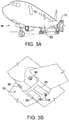
FIG. 3A is a schematic illustration of an aircraft that can incorporate various embodiments of the present disclosure; -
FIG. 3B is a schematic illustration of a bay section of the aircraft ofFIG. 3A ; -
FIG. 4 is a schematic depiction of an example embodiment of an aircraft air treatment system. - An exemplary fluidized bed assembly for treating titanium dioxide particles is shown in
FIG. 1 . As shown inFIG. 1 , the assembly includes a fluidizedbed 12 havinginlet openings 14 disposed at one end of the fluidizedbed 12 and an outlet opening 16 disposed at the opposite end of the fluidizedbed 12. The fluidizedbed 12 is disposed inside of anouter tubing 18, withoutlet 16 extending to the outside ofouter tubing 18. During operation, the fluidized bed assembly is disposed in a furnace (not shown) to provide heat.Thermocouples bed 12 andouter tubing 18, respectively. Aninlet 20 is connected to agas feed line 22. Agas source 24 such as a storage tank or a gas-generating reactor is connected togas feed line 22 to supply a gas feed to the fluidizedbed 12. Other components, such asmass flow controller 26,pressure regulating valve 28,pressure sensor 30, and shut-offvalves gas feed line 22 for monitoring and controlling the flow rate and pressure of the gas delivered to the fluidizedbed 12. Fluidizedbed outlet 16 is connected tooutlet line 36 that includes acheck valve 37, and is connected to a water or otherliquid bubbler 38. Ableed line 40 with shut-offvalve 42 also connectsfeed line 22 to thebubbler 38, which is vented to atmosphere throughexhaust port 44. - In operation, a gas mixture comprising nitrogen and hydrogen, or a gas comprising ammonia and hydrogen, or a gas comprising nitrogen, hydrogen, and ammonia, or a gas of pure ammonia or consisting essentially of ammonia, from gas source(s) 24 is fed through
feed line 22, with the flow rate and gas pressure controlled bymass flow controller 26 andpressure regulating valve 28. In some embodiments, the gas comprises an amount of hydrogen in a range having a low end of 5 mol%, or 10 mol%, or 30 mol%, or 40 mol%, or 60 mol%, and an upper end of 90 mol%, or 80 mol%, or 85 mol%, or 90 mol%, or 95 mol%, based on the total mole percentage of nitrogen, hydrogen, and/or ammonia, in the gas. This approach can also be taken with NH3 / H2 mixtures which can also be used in controlled nitriding processes. Therefore, this technique can be applied with NH3 concentrations ranging from 5 - 95% and respective H2 concentrations between 95 and 5%. The above upper and lower range endpoints can be independently combined to disclose a variety of different ranges, and each possible combination of endpoints to form a range is hereby expressly disclosed. Other gases (e.g., helium, argon) can be included as well, and the gas can in some embodiments comprise an amount of nitrogen in a range having a low end of 5 mol%, or 10 mol%, or 15 mol%, or 20 mol%, and an upper end of 40 mol%, or 60 mol%, or 70 mol%, based on the total moles of gas. The above upper and lower range endpoints can be independently combined to disclose a variety of different ranges, and each possible combination of endpoints to form a range is hereby expressly disclosed. The nitrogen- and hydrogen-containing gas enters thefurnace 18 throughinlet 20. The gas can be heated, for example, as it passes through the space betweenfluidized bed 12 andouter tubing 18 to enter thefluidized bed 12 throughinlet 14. Thefluidized bed 12 hasTiO2 particles 46 disposed therein, and the upward gas flow rate through the fluidized bed applies sufficient upward force to theparticles 46 to counteract the force of gravity acting on the particles so that they are suspended in a fluid configuration in the fluidized bed space. The gas flow is generally maintained below levels that would carry entrained particles out of the fluidized bed throughoutlet 16, andoutlet 16 can also be fitted with a filter or screen to further assist in keepingmetal powder particles 46 from exiting thefluidized bed 12. Nitrogen-containing gas exits thefluidized bed 12 throughoutlet 16 and flows viaoutlet line 36 to thebubbler 38, from which it is exhausted to the atmosphere throughexhaust port 44. - In some embodiments, treatment of the TiO2 particles is continued for a duration and/or under conditions to provide a target nitrogen content integrated into the atomic lattice structure of the metal oxide of the particles. Although the disclosure is not bound by any particular theory or mode of operation, it is believed that a target nitrogen content can provide enhanced photocatalytic activity. In some embodiments, treatment of the particles in the fluidized bed imparts a nitrogen content to the particles in a range having a lower limit of 0.25 at.%, 1.25 at.%, or 5 at.%, and an upper limit of 10 at.%, 25 at.%, or 50 at. %. These range limits can be independently combined to form different ranges, and each range represented by a possible combination of the above range limits is hereby expressly disclosed. In some embodiments, the reaction temperature in the
fluidized bed 12 can be in a range having a lower limit of 200°C, 300°C, or 500°C, and an upper limit of 600°C, 700°C, or 800°C. These range limits can be independently combined to form different ranges, and each range represented by a possible combination of the above range limits is hereby expressly disclosed. The gas can flow at a velocity sufficient to create a fluid mixture with the particles. In some embodiments, the gas can flow through the fluidized bed at a velocity of 6 x 10⁻⁸ m/s (meters per second) (e.g., 0.003 ml/min for 1" OD reactor) to 0.2 m/s (e.g., 3745 ml/min for 1" OD reactor). The TiO2 particles can be treated in the fluidized bed for periods (i.e., contact time with the nitrogen-containing gas) for a duration in a range having a lower limit of 0.50 hours, 1.00 hours, or 3.00 hours, and an upper limit of 5.00 hours, 10.00 hours, or 20.00 hours. These range limits can be independently combined to form different ranges, and each range represented by a possible combination of the above range limits is hereby expressly disclosed. In batch mode, such as depicted in the treatment scheme shown inFIG. 1 , the fluidized bed is operated for the specified amount of time to achieve the desired contact time. In a continuous mode, throughput of the particles through the fluidized bed can be adjusted to achieve an average residence time equal to the desired contact time. - The particle size of the TiO2 particles can vary depending on factors such as the desired final particle size, fluidized bed parameters such as velocity of gas flow in the fluidized bed, etc. In some embodiments, particle size is in a range having a lower limit of 100 nm, 300 nm, or 700 nm, and an upper limit of 0.25 µm, 10 µm, or 50 µm. These range limits can be independently combined to form different ranges, and each range represented by a possible combination of the above range limits is hereby expressly disclosed. In some embodiments, the TiO2 can be in anatase form, e.g., ≥ 99 wt.% anatase form. In some embodiments, the TiO2 can be in a mixed anatase/rutile form, e.g., with an anatase:rutile weight ratio of 99:1 to 1:99.
- In some embodiments, the fluidized bed can provide various technical benefits (e.g., compared to the fixed beds that are conventionally used with ammonia to make metal nitrides such as vanadium nitride), including but not limited to providing uniform reaction conditions for the population of TiO2 particles, avoiding localized hot spots that can occur in fixed beds. The gas mixture can comprise hydrogen and nitrogen, or ammonia, or a mixture of hydrogen, nitrogen, and ammonia. The use of a gas mixture comprising nitrogen and hydrogen can in some embodiments help to avoid heat transfer problems associated with the endothermic decomposition of ammonia, and also allow for recycling of essentially all of the gas fed to the fluidized bed. In some embodiments, the gas fed to the fluidized bed is free of ammonia. In some embodiments, the gas mixture comprises nitrogen and hydrogen, and also comprises ammonia in an amount less than or equal to 5 mol %. In some embodiments, the gas mixture comprises nitrogen and hydrogen, and also comprises ammonia in an amount less than or equal to 10 mol %. In some embodiments, the gas mixture comprises nitrogen and hydrogen, and also comprises ammonia in an amount of from 5 mol % to less than 100 mol % ammonia. In some embodiments, the gas mixture comprises ammonia without a nitrogen/hydrogen mixture.
- After emergence from the fluidized bed, the TiO2 particles 46 can in some embodiments be subjected to further processing before integration into an air treatment device or system. For example, in some embodiments, the TiO2 powder can be separated into different particle size ranges that can be targeted toward different applications.
- With reference now to
FIG. 2 , the Figure schematically depicts an example embodiment of agas treatment system 50. As shown inFIG. 2 , agas 52 to be treated is introduced to aphotocatalytic treatment module 54. Thephotocatalytic module 54 includes photocatalyticTiO2 particles 46 taken from the fluidized bed 12 (FIG. 1 ). The TiO2 particles can be disposed on a substrate such as a porous substrate, for example a carbon or ceramic substrate. Various substrate configurations can be utilized such as a honeycomb, corrugated sheet, fiber or other monolith structure. Ceramics for substrates can include but are not limited to sillimanite, petalite, cordierite, mullite, Zircon, Zircon mullite, spodumene, alumina, or alumina-titanate. The photocatalytic particles can be deposited onto the substrate by dispersing in a fluid medium and applying to the substrate. Application techniques can include, but are not limited to, wash-coating, dip-coating, spraying, rolling, brushing, and other manual or automated application techniques. A light source such as aUV light source 56 is directed onto the photocatalyticTiO2 particles 46 to induce photocatalytic formation of reactive species, for example formation of hydroxyl ions from water molecules in thegas 52, that can react with other species in thegas 52 such as organic contaminants.Treated gas 59 exits from an outlet of thephotocatalytic treatment module 54. - A notable application is for photocatalytic treatment of cabin air onboard pressurized aircraft. As shown in
FIGS. 3A-3B , an aircraft can include anaircraft body 101, which can include one ormore bays 103 beneath a center wing box. Thebay 103 can contain and/or support one or more components of theaircraft 101. For example, in some configurations, the aircraft can include environmental control systems and/or fuel inerting systems within thebay 103. As shown inFIG. 1B , thebay 103 includesbay doors 105 that enable installation and access to one or more components (e.g., environmental control systems, fuel inerting systems, etc.). During operation of environmental control systems and/or fuel inerting systems of the aircraft, air that is external to the aircraft can flow into one or moreram air inlets 107. The outside air may then be directed to various system components (e.g., environmental conditioning system (ECS) heat exchangers) within the aircraft. Some air may be exhausted through one or more ramair exhaust outlets 109. Also shown inFIG. 3A , the aircraft includes one ormore engines 111. Theengines 111 are typically mounted on wings of the aircraft and are connected to fuel tanks (not shown) in the wings, but may be located at other locations depending on the specific aircraft configuration. In some aircraft configurations, air can be bled from theengines 111 and supplied to environmental control systems and/or fuel inerting systems, as will be appreciated by those of skill in the art. - An example embodiment of an aircraft cabin air ozone removal system is schematically depicted in
FIG. 4 . As shown inFIG. 4 , aircraftcabin air system 60 receives outsideambient air 62 and directs it to acompressor 64. Thecompressor 64 can be a compressor section of a turbo-compressor aircraft engine, or can be an electrically-powered compressor. Thecompressor 64 compresses the air to a pressure of at least 15 psia, and typically to a greater pressure, which is then reduced by an aircraft environmental control system (ECS)pack 68. In some embodiments, a turbo-compressor aircraft engine can provide bleed flow at 40-60 psi, whereas an electrically-powered compressor on a bleed-less or low-bleed aircraft architecture may provide compressed air at lower pressures (e.g., about 20 psi). Thecompressor 64 produces compressedair 66, which is directed to theECS pack 68. As depicted in the example embodiment ofFIG. 4 , theECS pack 68 includes multiple modules in addition to thephotocatalytic module 54, any of which can optionally be used individually in combination with thephotocatalytic module 54 or can be combined in groups with thephotocatalytic module 54. As shown inFIG. 4 , theair 66 enters afilter module 72 such as a HEPA (high efficiency particulate absorber) filter, and is directed to a VOC (volatile organic content)absorber 74 such as an activated carbon filter that can adsorb VOC carbon and later discharge it during regeneration, and then to thephotocatalytic module 54. Lastly, the air flow is directed through anozone removal module 78, such as a noble metal catalytic module. Noble metal catalysts for the removal of ozone can include a metal selected from ruthenium, rhodium, palladium, iridium, platinum, gold, or combinations comprising any of the foregoing. In some embodiments, the noble metal is selected from palladium or platinum and their alloys. Noble metal catalysts can provide significant catalytic activity in the temperature range of 50-350°C, and in some embodiments the noble metal catalyst is disposed in an airflow path in that temperature range. - The ECS pack can also include other customary components for air cycle cooling systems, including heat exchangers, compressors (e.g., turbine-blade compressors), turbines, and heat exchanger/water removal units. Air cycle cooling systems can be based on three-wheel architecture (a fan, a compressor, and a turbine) or four-wheel architecture (a fan, a compressor, and two turbines). In some embodiments, the ECS pack cools bleed air in a ram air heat exchanger, partially recompresses it in a turbine-powered compressor, cools the partially re-compressed air in a second pass through the ram air heat exchanger, expands and further cools the air flow and removes water with a turbine in a flow loop with a heat exchanger water removal unit, and, in the case of a four-wheel architecture further expands and cools the air in a second turbine. The location of the
photocatalytic module 54 and the other modules in flow paths through the ECS pack can vary depending on the system operating parameters of the ECS pack, and the temperature and other environmental requirements for effective adsorptive and catalytic effect.FIG. 4 depicts an example embodiment, and modifications are contemplated. For example, the modules shown inFIG. 4 do not have to be disposed in the order shown inFIG. 4 , and can instead be disposed in different orders with respect to the direction of air flow. Also, the modules do not have to be lined up consecutively, but can instead be disposed at different paths along the air cycle process flow, with other ECS components disposed along the air flow path between any or all of the modules shown inFIG. 4 . - While the present disclosure has been described in detail in connection with only a limited number of embodiments, it should be readily understood that the present disclosure is not limited to such disclosed embodiments. Rather, the present disclosure can be modified to incorporate any number of variations, alterations, substitutions or equivalent arrangements not heretofore described, but which are commensurate with the spirit and scope of the present disclosure. Additionally, while various embodiments of the present disclosure have been described, it is to be understood that aspects of the present disclosure may include only some of the described embodiments. Accordingly, the present disclosure is not to be seen as limited by the foregoing description, but is only limited by the scope of the appended claims.
Claims (15)
- A method of making nitrogen-doped titanium dioxide, comprising:introducing a gas comprising hydrogen and nitrogen, or comprising hydrogen and ammonia, or comprising hydrogen, nitrogen, and ammonia to a fluidized bed;flowing the gas through the fluidized bed, and through particles comprising titanium dioxide in the fluidized bed to form a fluid mixture of the particles and the gas in the fluidized bed; andreacting the particles with the gas to form particles comprising titanium dioxide and nitrogen.
- The method of claim 1, wherein the gas comprises hydrogen and nitrogen.
- The method of claim 1, wherein the gas comprises hydrogen and ammonia.
- The method of claim 1, wherein the gas comprises hydrogen, nitrogen, and ammonia.
- The method of any preceding claim, wherein the particles have a diameter of 100 nm to 50 µm.
- The method of any preceding claim, wherein the titanium dioxide comprises at least 99 wt.% anatase titanium dioxide.
- The method of any of claims 1-5, wherein the titanium dioxide comprises anatase and rutile titanium dioxide with an anatase:rutile weight ratio of 99:1 to 1:99.
- The method of any preceding claim, comprising flowing the gas through the fluidized bed at a velocity of 6 x 10⁻⁸ m/s to 0.2 m/s.
- The method of any preceding claim, comprising introducing the gas to an outer chamber of the fluidized bed, flowing the gas to an inner chamber positioned within the outer chamber, and introducing the particles comprising titanium dioxide to the inner chamber to form the fluid mixture of the particles and the gas in the inner chamber.
- A method of making an air treatment device, comprising:making particles comprising titanium dioxide and nitrogen according to the method of any preceding claim; anddisposing the particles along an air flow path in operative communication with a light source.
- An air treatment method, comprising:making particles comprising titanium dioxide and nitrogen according to the method of any of claims 1-9;disposing the particles along an air flow path in operative communication with a light source; andactivating the light source and contacting the particles with air to be treated.
- The method of claim 11, wherein the air to be treated is delivered to a conditioned interior airspace onboard an aircraft, and wherein contacting the particles with the air to be treated comprises compressing outside low pressure air and contacting the compressed air with the particles.
- A system for making nitrogen-doped titanium dioxide, comprising:a gas source comprising hydrogen and nitrogen, or comprising hydrogen and ammonia, or comprising hydrogen, nitrogen, and ammonia;a source of titanium dioxide particles;a fluidized bed arranged to receive gas from the gas source and titanium dioxide particles from the source of titanium dioxide particles and form a fluid mixture of the particles in the gas.
- The system of claim 13, wherein the gas includes nitrogen.
- The system of claims 13 or 14, wherein the gas includes ammonia.
Applications Claiming Priority (1)
| Application Number | Priority Date | Filing Date | Title |
|---|---|---|---|
| US15/968,691 US11577224B2 (en) | 2018-05-01 | 2018-05-01 | Gas treatment method and materials |
Publications (1)
| Publication Number | Publication Date |
|---|---|
| EP3564189A1 true EP3564189A1 (en) | 2019-11-06 |
Family
ID=66630070
Family Applications (1)
| Application Number | Title | Priority Date | Filing Date |
|---|---|---|---|
| EP19172141.4A Pending EP3564189A1 (en) | 2018-05-01 | 2019-05-01 | Method for preparing nitrogen-doped titanium dioxide and air treatment method |
Country Status (2)
| Country | Link |
|---|---|
| US (2) | US11577224B2 (en) |
| EP (1) | EP3564189A1 (en) |
Families Citing this family (3)
| Publication number | Priority date | Publication date | Assignee | Title |
|---|---|---|---|---|
| US11577224B2 (en) | 2018-05-01 | 2023-02-14 | Hamilton Sundstrand Corporation | Gas treatment method and materials |
| US11835494B2 (en) | 2020-04-27 | 2023-12-05 | Saudi Arabian Oil Company | Fluidized bed for industrial hygiene applications |
| GB202007696D0 (en) * | 2020-05-22 | 2020-07-08 | Apollo Air Uk Ltd | An air purifying device |
Citations (5)
| Publication number | Priority date | Publication date | Assignee | Title |
|---|---|---|---|---|
| CN1557550A (en) * | 2004-02-06 | 2004-12-29 | 华东理工大学 | Method for preparing nanometer TiO(2-x)N(x) photocatalyst and fluidized bed reactor |
| JP2005047786A (en) * | 2002-09-18 | 2005-02-24 | Toshiba Ceramics Co Ltd | Titanium dioxide fine particles, method for producing the same, and method for producing visible light active photocatalyst |
| WO2012052624A1 (en) * | 2010-10-21 | 2012-04-26 | Oulun Yliopisto | Photocatalytic material |
| US20120121470A1 (en) * | 2010-08-05 | 2012-05-17 | Morito Yuko | Air purification system |
| US20120171079A1 (en) * | 2010-01-26 | 2012-07-05 | Morito Yuko | Photocatalyst element structure, ultraviolet radiation air purification system, photocatalyst sheet, and method of manufacturing photocatalyst sheet |
Family Cites Families (21)
| Publication number | Priority date | Publication date | Assignee | Title |
|---|---|---|---|---|
| SE429898B (en) * | 1980-01-16 | 1983-10-03 | Stora Kopparbergs Bergslags Ab | WASTE TO PREVENT PACKAGING BY REDUCTION IN FLOAT BED OF FINDED METAL OXIDE CONTENT |
| US4287156A (en) * | 1980-05-19 | 1981-09-01 | Curtiss-Wright Corporation | Fluidized bed reactor |
| US5817280A (en) * | 1993-11-15 | 1998-10-06 | Niro Holding A/S | Fluid bed for producing and/or processing a particulate material |
| JP3180603B2 (en) * | 1995-02-07 | 2001-06-25 | 信越化学工業株式会社 | Fluidized bed reactor for metal nitride production |
| US6794065B1 (en) * | 1999-08-05 | 2004-09-21 | Kabushiki Kaisha Toyota Chuo Kenkyusho | Photocatalytic material and photocatalytic article |
| JP3791901B2 (en) * | 2001-07-16 | 2006-06-28 | 株式会社ノリタケカンパニーリミテド | Photocatalyst holder and method for producing the same |
| EP1400491A3 (en) * | 2002-09-18 | 2005-01-19 | Toshiba Ceramics Co., Ltd. | Titanium dioxide fine particles and method for producing the same, and method for producing visible light activatable photocatalyst |
| US7547418B2 (en) | 2004-01-23 | 2009-06-16 | Gm Global Technology Operations, Inc. | Fluidized-bed reactor system |
| DE102004027549A1 (en) | 2004-04-07 | 2005-10-27 | Kronos International, Inc. | Carbonaceous titania photocatalyst and process for its preparation |
| WO2005102521A1 (en) * | 2004-04-20 | 2005-11-03 | Sumitomo Metal Industries, Ltd. | Titanium oxide base photocatalyst, process for producing the same and use thereof |
| US20060210798A1 (en) * | 2005-03-16 | 2006-09-21 | Clemens Burda | Doped metal oxide nanoparticles and methods for making and using same |
| CN1321738C (en) | 2005-04-29 | 2007-06-20 | 北京科技大学 | Production of nitrogen-doped anatase-type nanometer titanium dioxide |
| EP1908730A1 (en) | 2006-10-05 | 2008-04-09 | EMPA Eidgenössische Materialprüfungs- und Forschungsanstalt | Nitrogen doped titanium oxide nanoparticles |
| ITSA20080012A1 (en) * | 2008-05-29 | 2009-11-30 | Univ Degli Studi Salerno | CATALYTIC PHOTOREACTOR WITH HIGH LIGHT EFFICIENCY FOR INTENSIFIED PHOTOSSIDATION PROCESSES |
| US9095636B2 (en) | 2008-09-29 | 2015-08-04 | Carrier Corporation | Catalytic substrates and methods for creating catalytic coatings for indoor air quality applications |
| DE102009017409A1 (en) | 2008-10-04 | 2010-04-08 | Friedrich-Alexander-Universität Erlangen-Nürnberg | Azine-modified titanium dioxide photocatalyst and process for its preparation |
| US20100213046A1 (en) * | 2009-01-06 | 2010-08-26 | The Penn State Research Foundation | Titania nanotube arrays, methods of manufacture, and photocatalytic conversion of carbon dioxide using same |
| US9289739B2 (en) * | 2009-06-23 | 2016-03-22 | Chevron Philips Chemical Company Lp | Continuous preparation of calcined chemically-treated solid oxides |
| US8791044B2 (en) * | 2010-04-30 | 2014-07-29 | The United States Of America As Represented By The Administrator Of The U.S. Environmental Protection Agency | Doped titanium dioxide as a visible and sun light photo catalyst |
| FR3011819B1 (en) * | 2013-10-14 | 2017-04-07 | Liebherr-Aerospace Toulouse Sas | AIR TREATMENT SYSTEM, IN PARTICULAR AT LOW TEMPERATURE, FOR AN AIRCRAFT. |
| US11577224B2 (en) | 2018-05-01 | 2023-02-14 | Hamilton Sundstrand Corporation | Gas treatment method and materials |
-
2018
- 2018-05-01 US US15/968,691 patent/US11577224B2/en active Active
-
2019
- 2019-05-01 EP EP19172141.4A patent/EP3564189A1/en active Pending
-
2023
- 2023-02-13 US US18/168,105 patent/US12036530B2/en active Active
Patent Citations (5)
| Publication number | Priority date | Publication date | Assignee | Title |
|---|---|---|---|---|
| JP2005047786A (en) * | 2002-09-18 | 2005-02-24 | Toshiba Ceramics Co Ltd | Titanium dioxide fine particles, method for producing the same, and method for producing visible light active photocatalyst |
| CN1557550A (en) * | 2004-02-06 | 2004-12-29 | 华东理工大学 | Method for preparing nanometer TiO(2-x)N(x) photocatalyst and fluidized bed reactor |
| US20120171079A1 (en) * | 2010-01-26 | 2012-07-05 | Morito Yuko | Photocatalyst element structure, ultraviolet radiation air purification system, photocatalyst sheet, and method of manufacturing photocatalyst sheet |
| US20120121470A1 (en) * | 2010-08-05 | 2012-05-17 | Morito Yuko | Air purification system |
| WO2012052624A1 (en) * | 2010-10-21 | 2012-04-26 | Oulun Yliopisto | Photocatalytic material |
Non-Patent Citations (1)
| Title |
|---|
| W. KUBO; T. TATSUMA, ANALYTICAL SCIENCES, vol. 20, 2004, pages 591 - 93 |
Also Published As
| Publication number | Publication date |
|---|---|
| US20190336952A1 (en) | 2019-11-07 |
| US12036530B2 (en) | 2024-07-16 |
| US11577224B2 (en) | 2023-02-14 |
| US20230182117A1 (en) | 2023-06-15 |
Similar Documents
| Publication | Publication Date | Title |
|---|---|---|
| US12036530B2 (en) | Gas treatment method and materials | |
| JP6064253B2 (en) | Catalytic filter system | |
| CN101233049B (en) | Catalytic reactive component reduction system and methods | |
| US20040258581A1 (en) | Bifunctional manganese oxide/titanium dioxide photocatalyst/thermocatalyst for improving indoor air quality | |
| US10745145B2 (en) | Contaminant removal for catalytic fuel tank inerting system | |
| JP2008522822A (en) | Photocatalyst protection method | |
| WO2009111677A2 (en) | System and methods for treating aircraft cabin air | |
| EP2581127A1 (en) | Method for air purification, preferably of volatile organic compounds | |
| JP2022113153A (en) | Air purification apparatuses, systems and methods for removing particulates, volatile organic compounds, and nitrous oxide-containing compounds | |
| US10850855B2 (en) | Catalytic ozone removal | |
| EP1726565A1 (en) | Carbon material and flue gas treatment apparatus | |
| US7462339B2 (en) | Metallic foam trap for poisons: aircraft ozone | |
| US7132086B2 (en) | Environmental control system including vapor cycle system and isothermal CATOX/PTF | |
| US11767222B2 (en) | Activated carbon method and material | |
| EP3482816B1 (en) | Closed-environment with air purification system | |
| Perry et al. | Atmosphere revitalization technology development for crewed space exploration | |
| EP0993857A1 (en) | Method for the catalytic oxidation of VOC/CO in the presence of organosilicate compounds | |
| US10799830B2 (en) | Reduced temperature hydrocarbon burner for enclosed environments | |
| WO2024261217A1 (en) | A process for treating a catalyst arranged for catalytic oxidation of at least one volatile organic compound (voc), and a catalyst treatment system for use in said process | |
| Nalette et al. | A Semi-Continuous, Regenerable System for Trace Contaminant Control in Closed Atmospheres | |
| TW201325701A (en) | Catalytic filter system | |
| NZ601610B (en) | Catalytic filter system | |
| Karki | Application of TiO2 Photocatalysis for the Treatment of NOx |
Legal Events
| Date | Code | Title | Description |
|---|---|---|---|
| PUAI | Public reference made under article 153(3) epc to a published international application that has entered the european phase |
Free format text: ORIGINAL CODE: 0009012 |
|
| STAA | Information on the status of an ep patent application or granted ep patent |
Free format text: STATUS: THE APPLICATION HAS BEEN PUBLISHED |
|
| AK | Designated contracting states |
Kind code of ref document: A1 Designated state(s): AL AT BE BG CH CY CZ DE DK EE ES FI FR GB GR HR HU IE IS IT LI LT LU LV MC MK MT NL NO PL PT RO RS SE SI SK SM TR |
|
| AX | Request for extension of the european patent |
Extension state: BA ME |
|
| STAA | Information on the status of an ep patent application or granted ep patent |
Free format text: STATUS: REQUEST FOR EXAMINATION WAS MADE |
|
| 17P | Request for examination filed |
Effective date: 20191126 |
|
| RBV | Designated contracting states (corrected) |
Designated state(s): AL AT BE BG CH CY CZ DE DK EE ES FI FR GB GR HR HU IE IS IT LI LT LU LV MC MK MT NL NO PL PT RO RS SE SI SK SM TR |
|
| STAA | Information on the status of an ep patent application or granted ep patent |
Free format text: STATUS: EXAMINATION IS IN PROGRESS |
|
| 17Q | First examination report despatched |
Effective date: 20210409 |