EP3564135A1 - Tank support assembly for a vehicle - Google Patents
Tank support assembly for a vehicle Download PDFInfo
- Publication number
- EP3564135A1 EP3564135A1 EP19172695.9A EP19172695A EP3564135A1 EP 3564135 A1 EP3564135 A1 EP 3564135A1 EP 19172695 A EP19172695 A EP 19172695A EP 3564135 A1 EP3564135 A1 EP 3564135A1
- Authority
- EP
- European Patent Office
- Prior art keywords
- magnets
- tank
- storage tank
- assembly
- tank assembly
- Prior art date
- Legal status (The legal status is an assumption and is not a legal conclusion. Google has not performed a legal analysis and makes no representation as to the accuracy of the status listed.)
- Granted
Links
Images




Classifications
-
- F—MECHANICAL ENGINEERING; LIGHTING; HEATING; WEAPONS; BLASTING
- F17—STORING OR DISTRIBUTING GASES OR LIQUIDS
- F17C—VESSELS FOR CONTAINING OR STORING COMPRESSED, LIQUEFIED OR SOLIDIFIED GASES; FIXED-CAPACITY GAS-HOLDERS; FILLING VESSELS WITH, OR DISCHARGING FROM VESSELS, COMPRESSED, LIQUEFIED, OR SOLIDIFIED GASES
- F17C3/00—Vessels not under pressure
- F17C3/02—Vessels not under pressure with provision for thermal insulation
- F17C3/08—Vessels not under pressure with provision for thermal insulation by vacuum spaces, e.g. Dewar flask
-
- F—MECHANICAL ENGINEERING; LIGHTING; HEATING; WEAPONS; BLASTING
- F16—ENGINEERING ELEMENTS AND UNITS; GENERAL MEASURES FOR PRODUCING AND MAINTAINING EFFECTIVE FUNCTIONING OF MACHINES OR INSTALLATIONS; THERMAL INSULATION IN GENERAL
- F16C—SHAFTS; FLEXIBLE SHAFTS; ELEMENTS OR CRANKSHAFT MECHANISMS; ROTARY BODIES OTHER THAN GEARING ELEMENTS; BEARINGS
- F16C32/00—Bearings not otherwise provided for
- F16C32/04—Bearings not otherwise provided for using magnetic or electric supporting means
- F16C32/0406—Magnetic bearings
- F16C32/0408—Passive magnetic bearings
- F16C32/0423—Passive magnetic bearings with permanent magnets on both parts repelling each other
- F16C32/0425—Passive magnetic bearings with permanent magnets on both parts repelling each other for radial load mainly
-
- B—PERFORMING OPERATIONS; TRANSPORTING
- B64—AIRCRAFT; AVIATION; COSMONAUTICS
- B64G—COSMONAUTICS; VEHICLES OR EQUIPMENT THEREFOR
- B64G1/00—Cosmonautic vehicles
- B64G1/22—Parts of, or equipment specially adapted for fitting in or to, cosmonautic vehicles
- B64G1/40—Arrangements or adaptations of propulsion systems
- B64G1/402—Propellant tanks; Feeding propellants
- B64G1/4022—Arrangements of tanks in or on spacecraft
-
- B—PERFORMING OPERATIONS; TRANSPORTING
- B64—AIRCRAFT; AVIATION; COSMONAUTICS
- B64G—COSMONAUTICS; VEHICLES OR EQUIPMENT THEREFOR
- B64G1/00—Cosmonautic vehicles
- B64G1/22—Parts of, or equipment specially adapted for fitting in or to, cosmonautic vehicles
- B64G1/46—Arrangements or adaptations of devices for control of environment or living conditions
- B64G1/50—Arrangements or adaptations of devices for control of environment or living conditions for temperature control
-
- F—MECHANICAL ENGINEERING; LIGHTING; HEATING; WEAPONS; BLASTING
- F16—ENGINEERING ELEMENTS AND UNITS; GENERAL MEASURES FOR PRODUCING AND MAINTAINING EFFECTIVE FUNCTIONING OF MACHINES OR INSTALLATIONS; THERMAL INSULATION IN GENERAL
- F16L—PIPES; JOINTS OR FITTINGS FOR PIPES; SUPPORTS FOR PIPES, CABLES OR PROTECTIVE TUBING; MEANS FOR THERMAL INSULATION IN GENERAL
- F16L59/00—Thermal insulation in general
- F16L59/06—Arrangements using an air layer or vacuum
-
- H—ELECTRICITY
- H01—ELECTRIC ELEMENTS
- H01F—MAGNETS; INDUCTANCES; TRANSFORMERS; SELECTION OF MATERIALS FOR THEIR MAGNETIC PROPERTIES
- H01F7/00—Magnets
- H01F7/02—Permanent magnets [PM]
-
- H—ELECTRICITY
- H01—ELECTRIC ELEMENTS
- H01F—MAGNETS; INDUCTANCES; TRANSFORMERS; SELECTION OF MATERIALS FOR THEIR MAGNETIC PROPERTIES
- H01F7/00—Magnets
- H01F7/02—Permanent magnets [PM]
- H01F7/0231—Magnetic circuits with PM for power or force generation
- H01F7/0252—PM holding devices
- H01F7/0268—Magnetic cylinders
-
- B—PERFORMING OPERATIONS; TRANSPORTING
- B64—AIRCRAFT; AVIATION; COSMONAUTICS
- B64G—COSMONAUTICS; VEHICLES OR EQUIPMENT THEREFOR
- B64G1/00—Cosmonautic vehicles
- B64G1/22—Parts of, or equipment specially adapted for fitting in or to, cosmonautic vehicles
- B64G1/40—Arrangements or adaptations of propulsion systems
- B64G1/402—Propellant tanks; Feeding propellants
- B64G1/4021—Tank construction; Details thereof
-
- F—MECHANICAL ENGINEERING; LIGHTING; HEATING; WEAPONS; BLASTING
- F16—ENGINEERING ELEMENTS AND UNITS; GENERAL MEASURES FOR PRODUCING AND MAINTAINING EFFECTIVE FUNCTIONING OF MACHINES OR INSTALLATIONS; THERMAL INSULATION IN GENERAL
- F16C—SHAFTS; FLEXIBLE SHAFTS; ELEMENTS OR CRANKSHAFT MECHANISMS; ROTARY BODIES OTHER THAN GEARING ELEMENTS; BEARINGS
- F16C2326/00—Articles relating to transporting
- F16C2326/47—Cosmonautic vehicles, i.e. bearings adapted for use in outer-space
-
- F—MECHANICAL ENGINEERING; LIGHTING; HEATING; WEAPONS; BLASTING
- F17—STORING OR DISTRIBUTING GASES OR LIQUIDS
- F17C—VESSELS FOR CONTAINING OR STORING COMPRESSED, LIQUEFIED OR SOLIDIFIED GASES; FIXED-CAPACITY GAS-HOLDERS; FILLING VESSELS WITH, OR DISCHARGING FROM VESSELS, COMPRESSED, LIQUEFIED, OR SOLIDIFIED GASES
- F17C2201/00—Vessel construction, in particular geometry, arrangement or size
- F17C2201/01—Shape
- F17C2201/0104—Shape cylindrical
-
- F—MECHANICAL ENGINEERING; LIGHTING; HEATING; WEAPONS; BLASTING
- F17—STORING OR DISTRIBUTING GASES OR LIQUIDS
- F17C—VESSELS FOR CONTAINING OR STORING COMPRESSED, LIQUEFIED OR SOLIDIFIED GASES; FIXED-CAPACITY GAS-HOLDERS; FILLING VESSELS WITH, OR DISCHARGING FROM VESSELS, COMPRESSED, LIQUEFIED, OR SOLIDIFIED GASES
- F17C2201/00—Vessel construction, in particular geometry, arrangement or size
- F17C2201/01—Shape
- F17C2201/0104—Shape cylindrical
- F17C2201/0109—Shape cylindrical with exteriorly curved end-piece
-
- F—MECHANICAL ENGINEERING; LIGHTING; HEATING; WEAPONS; BLASTING
- F17—STORING OR DISTRIBUTING GASES OR LIQUIDS
- F17C—VESSELS FOR CONTAINING OR STORING COMPRESSED, LIQUEFIED OR SOLIDIFIED GASES; FIXED-CAPACITY GAS-HOLDERS; FILLING VESSELS WITH, OR DISCHARGING FROM VESSELS, COMPRESSED, LIQUEFIED, OR SOLIDIFIED GASES
- F17C2201/00—Vessel construction, in particular geometry, arrangement or size
- F17C2201/01—Shape
- F17C2201/0104—Shape cylindrical
- F17C2201/0119—Shape cylindrical with flat end-piece
-
- F—MECHANICAL ENGINEERING; LIGHTING; HEATING; WEAPONS; BLASTING
- F17—STORING OR DISTRIBUTING GASES OR LIQUIDS
- F17C—VESSELS FOR CONTAINING OR STORING COMPRESSED, LIQUEFIED OR SOLIDIFIED GASES; FIXED-CAPACITY GAS-HOLDERS; FILLING VESSELS WITH, OR DISCHARGING FROM VESSELS, COMPRESSED, LIQUEFIED, OR SOLIDIFIED GASES
- F17C2201/00—Vessel construction, in particular geometry, arrangement or size
- F17C2201/01—Shape
- F17C2201/0133—Shape toroidal
-
- F—MECHANICAL ENGINEERING; LIGHTING; HEATING; WEAPONS; BLASTING
- F17—STORING OR DISTRIBUTING GASES OR LIQUIDS
- F17C—VESSELS FOR CONTAINING OR STORING COMPRESSED, LIQUEFIED OR SOLIDIFIED GASES; FIXED-CAPACITY GAS-HOLDERS; FILLING VESSELS WITH, OR DISCHARGING FROM VESSELS, COMPRESSED, LIQUEFIED, OR SOLIDIFIED GASES
- F17C2201/00—Vessel construction, in particular geometry, arrangement or size
- F17C2201/01—Shape
- F17C2201/0147—Shape complex
- F17C2201/0157—Polygonal
-
- F—MECHANICAL ENGINEERING; LIGHTING; HEATING; WEAPONS; BLASTING
- F17—STORING OR DISTRIBUTING GASES OR LIQUIDS
- F17C—VESSELS FOR CONTAINING OR STORING COMPRESSED, LIQUEFIED OR SOLIDIFIED GASES; FIXED-CAPACITY GAS-HOLDERS; FILLING VESSELS WITH, OR DISCHARGING FROM VESSELS, COMPRESSED, LIQUEFIED, OR SOLIDIFIED GASES
- F17C2201/00—Vessel construction, in particular geometry, arrangement or size
- F17C2201/05—Size
- F17C2201/054—Size medium (>1 m3)
-
- F—MECHANICAL ENGINEERING; LIGHTING; HEATING; WEAPONS; BLASTING
- F17—STORING OR DISTRIBUTING GASES OR LIQUIDS
- F17C—VESSELS FOR CONTAINING OR STORING COMPRESSED, LIQUEFIED OR SOLIDIFIED GASES; FIXED-CAPACITY GAS-HOLDERS; FILLING VESSELS WITH, OR DISCHARGING FROM VESSELS, COMPRESSED, LIQUEFIED, OR SOLIDIFIED GASES
- F17C2201/00—Vessel construction, in particular geometry, arrangement or size
- F17C2201/05—Size
- F17C2201/056—Small (<1 m3)
-
- F—MECHANICAL ENGINEERING; LIGHTING; HEATING; WEAPONS; BLASTING
- F17—STORING OR DISTRIBUTING GASES OR LIQUIDS
- F17C—VESSELS FOR CONTAINING OR STORING COMPRESSED, LIQUEFIED OR SOLIDIFIED GASES; FIXED-CAPACITY GAS-HOLDERS; FILLING VESSELS WITH, OR DISCHARGING FROM VESSELS, COMPRESSED, LIQUEFIED, OR SOLIDIFIED GASES
- F17C2203/00—Vessel construction, in particular walls or details thereof
- F17C2203/01—Reinforcing or suspension means
- F17C2203/014—Suspension means
- F17C2203/017—Magnetic means
-
- F—MECHANICAL ENGINEERING; LIGHTING; HEATING; WEAPONS; BLASTING
- F17—STORING OR DISTRIBUTING GASES OR LIQUIDS
- F17C—VESSELS FOR CONTAINING OR STORING COMPRESSED, LIQUEFIED OR SOLIDIFIED GASES; FIXED-CAPACITY GAS-HOLDERS; FILLING VESSELS WITH, OR DISCHARGING FROM VESSELS, COMPRESSED, LIQUEFIED, OR SOLIDIFIED GASES
- F17C2203/00—Vessel construction, in particular walls or details thereof
- F17C2203/03—Thermal insulations
- F17C2203/0391—Thermal insulations by vacuum
-
- F—MECHANICAL ENGINEERING; LIGHTING; HEATING; WEAPONS; BLASTING
- F17—STORING OR DISTRIBUTING GASES OR LIQUIDS
- F17C—VESSELS FOR CONTAINING OR STORING COMPRESSED, LIQUEFIED OR SOLIDIFIED GASES; FIXED-CAPACITY GAS-HOLDERS; FILLING VESSELS WITH, OR DISCHARGING FROM VESSELS, COMPRESSED, LIQUEFIED, OR SOLIDIFIED GASES
- F17C2203/00—Vessel construction, in particular walls or details thereof
- F17C2203/06—Materials for walls or layers thereof; Properties or structures of walls or their materials
- F17C2203/0602—Wall structures; Special features thereof
- F17C2203/0612—Wall structures
- F17C2203/0626—Multiple walls
- F17C2203/0629—Two walls
-
- F—MECHANICAL ENGINEERING; LIGHTING; HEATING; WEAPONS; BLASTING
- F17—STORING OR DISTRIBUTING GASES OR LIQUIDS
- F17C—VESSELS FOR CONTAINING OR STORING COMPRESSED, LIQUEFIED OR SOLIDIFIED GASES; FIXED-CAPACITY GAS-HOLDERS; FILLING VESSELS WITH, OR DISCHARGING FROM VESSELS, COMPRESSED, LIQUEFIED, OR SOLIDIFIED GASES
- F17C2221/00—Handled fluid, in particular type of fluid
- F17C2221/01—Pure fluids
- F17C2221/011—Oxygen
-
- F—MECHANICAL ENGINEERING; LIGHTING; HEATING; WEAPONS; BLASTING
- F17—STORING OR DISTRIBUTING GASES OR LIQUIDS
- F17C—VESSELS FOR CONTAINING OR STORING COMPRESSED, LIQUEFIED OR SOLIDIFIED GASES; FIXED-CAPACITY GAS-HOLDERS; FILLING VESSELS WITH, OR DISCHARGING FROM VESSELS, COMPRESSED, LIQUEFIED, OR SOLIDIFIED GASES
- F17C2221/00—Handled fluid, in particular type of fluid
- F17C2221/01—Pure fluids
- F17C2221/012—Hydrogen
-
- F—MECHANICAL ENGINEERING; LIGHTING; HEATING; WEAPONS; BLASTING
- F17—STORING OR DISTRIBUTING GASES OR LIQUIDS
- F17C—VESSELS FOR CONTAINING OR STORING COMPRESSED, LIQUEFIED OR SOLIDIFIED GASES; FIXED-CAPACITY GAS-HOLDERS; FILLING VESSELS WITH, OR DISCHARGING FROM VESSELS, COMPRESSED, LIQUEFIED, OR SOLIDIFIED GASES
- F17C2221/00—Handled fluid, in particular type of fluid
- F17C2221/08—Ergols, e.g. hydrazine
-
- F—MECHANICAL ENGINEERING; LIGHTING; HEATING; WEAPONS; BLASTING
- F17—STORING OR DISTRIBUTING GASES OR LIQUIDS
- F17C—VESSELS FOR CONTAINING OR STORING COMPRESSED, LIQUEFIED OR SOLIDIFIED GASES; FIXED-CAPACITY GAS-HOLDERS; FILLING VESSELS WITH, OR DISCHARGING FROM VESSELS, COMPRESSED, LIQUEFIED, OR SOLIDIFIED GASES
- F17C2223/00—Handled fluid before transfer, i.e. state of fluid when stored in the vessel or before transfer from the vessel
- F17C2223/01—Handled fluid before transfer, i.e. state of fluid when stored in the vessel or before transfer from the vessel characterised by the phase
- F17C2223/0146—Two-phase
- F17C2223/0153—Liquefied gas, e.g. LPG, GPL
- F17C2223/0161—Liquefied gas, e.g. LPG, GPL cryogenic, e.g. LNG, GNL, PLNG
-
- F—MECHANICAL ENGINEERING; LIGHTING; HEATING; WEAPONS; BLASTING
- F17—STORING OR DISTRIBUTING GASES OR LIQUIDS
- F17C—VESSELS FOR CONTAINING OR STORING COMPRESSED, LIQUEFIED OR SOLIDIFIED GASES; FIXED-CAPACITY GAS-HOLDERS; FILLING VESSELS WITH, OR DISCHARGING FROM VESSELS, COMPRESSED, LIQUEFIED, OR SOLIDIFIED GASES
- F17C2223/00—Handled fluid before transfer, i.e. state of fluid when stored in the vessel or before transfer from the vessel
- F17C2223/03—Handled fluid before transfer, i.e. state of fluid when stored in the vessel or before transfer from the vessel characterised by the pressure level
- F17C2223/033—Small pressure, e.g. for liquefied gas
-
- F—MECHANICAL ENGINEERING; LIGHTING; HEATING; WEAPONS; BLASTING
- F17—STORING OR DISTRIBUTING GASES OR LIQUIDS
- F17C—VESSELS FOR CONTAINING OR STORING COMPRESSED, LIQUEFIED OR SOLIDIFIED GASES; FIXED-CAPACITY GAS-HOLDERS; FILLING VESSELS WITH, OR DISCHARGING FROM VESSELS, COMPRESSED, LIQUEFIED, OR SOLIDIFIED GASES
- F17C2260/00—Purposes of gas storage and gas handling
- F17C2260/03—Dealing with losses
- F17C2260/031—Dealing with losses due to heat transfer
- F17C2260/033—Dealing with losses due to heat transfer by enhancing insulation
-
- F—MECHANICAL ENGINEERING; LIGHTING; HEATING; WEAPONS; BLASTING
- F17—STORING OR DISTRIBUTING GASES OR LIQUIDS
- F17C—VESSELS FOR CONTAINING OR STORING COMPRESSED, LIQUEFIED OR SOLIDIFIED GASES; FIXED-CAPACITY GAS-HOLDERS; FILLING VESSELS WITH, OR DISCHARGING FROM VESSELS, COMPRESSED, LIQUEFIED, OR SOLIDIFIED GASES
- F17C2270/00—Applications
- F17C2270/01—Applications for fluid transport or storage
- F17C2270/0186—Applications for fluid transport or storage in the air or in space
- F17C2270/0189—Planes
-
- F—MECHANICAL ENGINEERING; LIGHTING; HEATING; WEAPONS; BLASTING
- F17—STORING OR DISTRIBUTING GASES OR LIQUIDS
- F17C—VESSELS FOR CONTAINING OR STORING COMPRESSED, LIQUEFIED OR SOLIDIFIED GASES; FIXED-CAPACITY GAS-HOLDERS; FILLING VESSELS WITH, OR DISCHARGING FROM VESSELS, COMPRESSED, LIQUEFIED, OR SOLIDIFIED GASES
- F17C2270/00—Applications
- F17C2270/01—Applications for fluid transport or storage
- F17C2270/0186—Applications for fluid transport or storage in the air or in space
- F17C2270/0194—Applications for fluid transport or storage in the air or in space for use under microgravity conditions, e.g. space
-
- F—MECHANICAL ENGINEERING; LIGHTING; HEATING; WEAPONS; BLASTING
- F17—STORING OR DISTRIBUTING GASES OR LIQUIDS
- F17C—VESSELS FOR CONTAINING OR STORING COMPRESSED, LIQUEFIED OR SOLIDIFIED GASES; FIXED-CAPACITY GAS-HOLDERS; FILLING VESSELS WITH, OR DISCHARGING FROM VESSELS, COMPRESSED, LIQUEFIED, OR SOLIDIFIED GASES
- F17C2270/00—Applications
- F17C2270/01—Applications for fluid transport or storage
- F17C2270/0186—Applications for fluid transport or storage in the air or in space
- F17C2270/0197—Rockets
Definitions
- aspects of the present disclosure generally relate to assemblies within vehicles that support storage tanks, such as cryogenic storage tanks within spacecraft.
- cryogenic fluids such as liquid hydrogen
- the vehicles may be spacecraft that travel within microgravity environments within space.
- the cryogenic fluids may be used for propellants (e.g., rocket fuel) and/or heating and cooling systems for sensitive electronic instruments (and/or other systems) onboard the vehicle carrying the storage tank.
- the vehicle carrying the storage tank may supply the cryogenic fluids to another vehicle or station.
- Cryogenic fluids are difficult to store for long durations because of a process known as boil-off. Heat transfer into the tanks causes the liquid to vaporize into a gas, thereby increasing the pressure of the tank. The excess gas must be dumped from the tank to avoid over-pressurization and thus usable fluid is lost over time.
- Some of the heat at the storage tank may be received via solar radiation that impinges upon the outer surfaces of the vehicle and conductively transfers through vehicle structures to the tank.
- Additional heat sources may include the electronics (e.g., avionics) onboard the vehicle, such as computing devices and sensors, and the propulsion system. For example, when rocket thrusters are activated, some heat may be conductively conveyed along vehicle structures to the tank.
- cryogenic fluids stored according to known systems are not able to be stored for sufficient durations to enable long trips (e.g., space missions).
- known systems are not able to store cryogenic fluids on vehicles for more than a day or so, substantially restricting the duration and distance of available trips when transporting cryogenic fluids.
- Certain examples of the present disclosure provide a tank support assembly for a vehicle that includes a vehicle structure and a storage tank assembly.
- the storage tank assembly is held in place relative to the vehicle structure via a magnetic support system.
- the magnetic support system includes tank magnets affixed to the storage tank assembly and structure magnets affixed to the vehicle structure.
- the tank magnets interact with the structure magnets to passively provide repulsive magnetic forces that constrain movement of the storage tank assembly relative to the vehicle structure without the tank magnets mechanically engaging the structure magnets.
- Certain examples of the present disclosure provide a tank support assembly for a vehicle that includes a vehicle structure and a storage tank assembly.
- the vehicle structure includes a plurality of structure magnets affixed thereto.
- the storage tank assembly is oriented along a height axis between top end thereof and a bottom end thereof that is opposite the top end.
- the storage tank assembly includes a plurality of tank magnets affixed thereto.
- the tank magnets include a top magnet affixed along the top end of the storage tank assembly and a bottom magnet affixed along the bottom end of the storage tank assembly.
- the top magnet and the bottom magnet interact with corresponding structure magnets located above and below the top and bottom ends of the storage tank assembly, respectively, to passively provide repulsive magnetic forces that vertically support and suspend the storage tank assembly along the height axis relative to the vehicle structure without the tank magnets mechanically engaging the structure magnets.
- the present invention also relates to a vehicle, such as a spacecraft, including a tank support assembly according to an embodiment of the present invention.
- Certain examples of the present disclosure provide in an embodiment a method for supporting a storage tank assembly in a vehicle.
- the method includes loading cryogenic fluid into a storage tank assembly within a vehicle structure of a vehicle, and suspending the storage tank assembly relative to the vehicle structure via a magnetic support system.
- the magnetic support system includes tank magnets affixed to the storage tank assembly and structure magnets affixed to the vehicle structure.
- the tank magnets interact with the structure magnets to passively provide repulsive magnetic forces that suspend the storage tank assembly relative to the vehicle structure without the tank magnets mechanically engaging the structure magnets.
- a system or assembly according to an embodiment of the invention reduces heat transfer from a vehicle structure to a storage tank containing cryogenic fluid to reduce boil-off of the cryogenic fluid and thereby increase the storage life of the cryogenic fluid.
- a system or assembly would be passive and not require energy stored within the vehicle, such as through active cooling of the storage tank or active support of the storage tank using electromagnets.
- certain examples of embodiments according to the present invention illustrated in the present disclosure provide a tank support assembly that reduces thermal conduction paths to cryogenic storage tanks on vehicles operating in microgravity environments via utilizing magnetic materials.
- the vehicles may be manned or unmanned spacecraft, satellites, space stations, or the like.
- the magnetic materials constrain the tank to the vehicle while significantly reducing or eliminating the structural linkages between the tank and the vehicle. Reducing or eliminating the structural linkages reduces conductive heat transfer to the tank from heat sources like the sun, on-board electronics, and propulsion systems.
- the reduction in heat transfer to the tank decreases boil-off of the cryogenic fluid within the tank, increasing the feasibility of using cryogenic fluids for long duration space missions.
- Certain examples of embodiments according to the present invention provide a tank support assembly for a vehicle that includes a vehicle structure and a storage tank assembly.
- the storage tank assembly is held in place relative to the vehicle structure via a magnetic support system.
- the magnetic support system includes tank magnets affixed to the storage tank assembly and structure magnets affixed to the vehicle structure.
- the tank magnets and structure magnets include permanent magnets (i.e. materials which have strong ferromagnetic properties) and/or diamagnets (i.e. materials which have strong diamagnetic properties).
- the tank magnets interact with the structure magnets to passively provide repulsive magnetic forces that constrain movement of the storage tank assembly relative to the vehicle structure in a microgravity environment without the tank magnets mechanically engaging the structure magnets.
- the tank support assembly of embodiments according to the present invention includes one or more diamagnets and/or mechanical support struts to stabilize the storage tank assembly relative to the vehicle structure.
- the mechanical struts tether the storage tank assembly to the vehicle structure.
- permanent magnets alone are not sufficient to stabilize the storage tank assembly, as described in Earnshaw's Theorem.
- the tank support assembly in various examples described herein may include permanent magnets with one or more mechanical struts, permanent magnets with diamagnets, or permanent magnets with both diamagnets and one or more mechanical struts.
- the storage tank assembly may contain a cryogenic fluid, such as liquid hydrogen, liquid oxygen, or the like.
- a cryogenic fluid such as liquid hydrogen, liquid oxygen, or the like.
- the vehicle within the microgravity environment may be a spacecraft traveling through space.
- the spacecraft may be in orbit around the Earth or another planet, or located at a stable or partially stable gravitational well known as a Lagrange point.
- the diamagnets described herein are materials with strong diamagnetic properties that repel an external magnetic field to which the materials are exposed, and the extent of repulsion is proportional to the strength of the applied magnetic field. Via this repulsion, the diamagnets passively provide restoring forces to balance and stabilize the storage tank assembly relative to the vehicle structure.
- the diamagnet may be affixed to the storage tank assembly, representing tank magnets, and/or affixed to the vehicle structure, representing structure magnets.
- the repulsive magnetic forces provided by the permanent magnets and the restoring forces provided by the diamagnets may fully suspend the storage tank assembly relative to the vehicle structure, at least in microgravity environments where there is no significant gravitational force to withstand.
- the diamagnets also constrain the storage tank assembly from moving out of position and leaving the vehicle. For example, there may be no mechanical engagement between the storage tank assembly and the vehicle structure, direct or indirect, such that a continuous gap surrounds an outer surface of the storage tank assembly.
- the full suspension of the storage tank assembly reduces heat transfer to the storage tank assembly by eliminating thermal conduction paths between the vehicle and the storage tank assembly. Reducing heat transfer conserves the cryogenic fluid within the storage tank assembly for longer periods of time, allowing for transporting the cryogenic fluid along longer trips covering greater distances.
- the vehicle in at least one example of embodiments according to the present invention includes one or more mechanical struts that couple the storage tank assembly to the vehicle structure when in the microgravity environment.
- the mechanical struts described in the examples herein are utilized for stabilizing the storage tank assembly that is suspended and constrained from leaving the vehicle by the magnetic support system.
- suspension of the storage tank assembly means that the non-contact repulsive forces provided by the magnetic support system at least partially support the weight of the storage tank assembly relative to the vehicle.
- the one or more mechanical struts or diamagnets stabilize the suspended storage tank assembly.
- the mechanical struts utilized in the examples described herein may be fewer, smaller, and/or less robust than the mechanical struts in known tank support assemblies because the mechanical struts described herein support less of the load than the struts in the known tank support assemblies.
- the mechanical struts described herein may be composed of material that is more thermally insulative (e.g., less thermally conductive) than the known struts, such as fiber-reinforced composites, fiberglass, plastics, or the like instead of metals.
- the reduced number, size, and thermal conductivity of the mechanical struts relative to the known tank support assemblies may substantially reduce the amount of heat transfer to the storage tank assembly, thereby extending the storage life of the cryogenic fluid.
- One or more examples of embodiments according to the present invention illustrated in the present disclosure utilize permanent magnets, and optionally also diamagnets, to eliminate some or all of the mechanical supports used in known tank support assemblies for in-space operation of spacecraft.
- the magnets and diamagnets allow the storage tank assembly to achieve stable suspension relative to a vehicle structure surrounding the storage tank assembly.
- the magnetic suspension is achieved in microgravity environments, such as in free-fall while the spacecraft is in orbit.
- the vehicle may have frangible and/or detachable mechanical elements that support and secure the tank during launch and uncouple from the tank upon reaching a microgravity environment. In the microgravity environment, the magnetic support system can meet all loading and vibrational requirements.
- the magnetic support system may include permanent magnets placed at strategic locations on the storage tank assembly that pair with magnets attached to the vehicle structure surrounding the tank to create an unstable equilibrium point at a desired steady state position. Diamagnets and/or minimal mechanical struts provide restoring forces for stabilizing the tank at the steady state position, to achieve a stable equilibrium point.
- the magnetic support system may be entirely passive, meaning that there is no power requirement to support and suspend the tank.
- the magnets on the tank interact with the magnets on the vehicle structure to passively provide repulsive magnetic forces that suspend the tank.
- the magnetic support system may not include electromagnets, superconductors which require active cooling systems, or the like.
- a technical effect of one or more of the examples of the tank support assembly of embodiments according to the present invention described herein is an extended storage life of cryogenic fluids within a storage tank assembly carried by a vehicle in microgravity environments, which enables longer mission durations and farther travel distances. Because there may be less boil-off of the cryogenic fluid, the vehicle may be able to transport more cryogenic fluid to a destination, such as another vehicle or a space station, for a given amount of energy expended during the trip than vehicles utilizing known tank support systems. Another technical effect may include energy conservation because the magnetic support system may be passive, without requiring an energy source to suspend the storage tank assembly. Another technical effect may be a weight savings through the reduction or complete elimination of heavy mechanical struts which would normally be necessary to fully support and suspend the storage tank assembly.
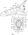
- FIG. 1 is a perspective view of a vehicle 100 according to an example of embodiments according to the present invention as illustrated in the present disclosure.
- the vehicle 100 is a spacecraft in the illustrated example, and is configured to travel in microgravity environments.
- microgravity environments experience reduced gravitational forces than the gravitational forces experienced on Earth (e.g., at sea level).
- the vehicle 100 may travel in the microgravity environment of space, such as in orbit around the Earth or another planet.
- the vehicle 100 in the illustrated example is a shuttle designed to carry people and cargo, but the vehicle 100 in other examples may be an unmanned vehicle that does not carry people.
- the vehicle 100 includes a main body or fuselage 102 and wings 104 extending from the body 102.
- the vehicle 100 carries a payload (e.g., cargo and/or passengers) within one or more compartments 106 of the body 102.
- a payload e.g., cargo and/or passengers
- the vehicle 100 includes a tank support assembly 108.
- the tank support assembly 108 includes a vehicle structure 110 and a storage tank assembly 112.
- the tank support assembly 108 also includes a magnetic support system 114 that supports and at least partially suspends the storage tank assembly 112 relative to the vehicle structure 110.
- a cross-sectional illustration of the tank support assembly 108 is shown in Figure 1 .
- the illustration in Figure 1 is intended for introducing the components of the tank support assembly 108 and may not necessarily represent the shapes, sizes, and arrangement of the components thereof, which are shown in more detail in the following figures.
- the storage tank assembly 112 is hollow and contains a cryogenic fluid 116.
- the cryogenic fluid 116 may be a propellant such as liquid hydrogen, liquid oxygen, or the like, stored at a very cold temperature.
- the storage tank assembly 112 may be insulated to reduce heat transfer from outside of the tank 112 into the cryogenic fluid 116.
- the storage tank assembly 112 is elongated along a height axis 118 of the storage tank assembly 112.
- the storage tank assembly 112 may be cylindrical and oriented about the height axis 118.
- the storage tank assembly 112 extends along the height axis 118 from a top end 120 thereof to a bottom end 122 that is opposite the top end 120.
- the storage tank assembly 112 has one or more side walls 124 defining a perimeter of the tank 112. Each of the one or more side walls 124 extends from the top end 120 to the bottom end 122.
- a single side wall 124 may define a circumference of the tank 112, although two different portions of the side wall 124 are shown in the illustrated cross-section.
- relative or spatial terms such as “top,” “bottom,” “left,” “right,” “front”, “rear”, “upper,” and “lower” are only used to identify and distinguish the referenced elements and do not necessarily require particular positions or orientations in the surrounding environment of the tank support assembly 108.
- the vehicle 100 may rotate in space such that the top end 120 may be below the bottom end 122 relative to the direction of gravitational force experienced on Earth.
- the relative or spatial terms are therefore specific to the orientations depicted in the figures.
- the vehicle structure 110 has walls 126 that at least partially surround the storage tank assembly 112.
- the walls 126 at least partially define a chamber 128 in which the storage tank assembly 112 is disposed.
- the tank support assembly 108 may be located within one of the compartments 106 of the body 102, and the vehicle structure 110 may represent part of, or may be attached to, the body 102.
- the walls 126 may be interior walls of the body 102 that define one of the compartments 106.
- the illustrated cross-section shows that the walls 126 surround the tank 112 above and below the top and bottom ends 120, 122, and on both left and right sides of the one or more side walls 124.
- the vehicle structure 110 may also longitudinally surround the tank 112 both in front of (e.g., out of the page) and behind (e.g., into the page) the tank 112.
- the vehicle structure 110 is mechanically spaced apart from the tank 112 via a gap 140 that fully surrounds the tank 112, such that the storage tank assembly 112 does not mechanically engage the vehicle structure 110.
- the tank 112 is supported and held in place relative to the vehicle structure 110 by the magnetic support system 114.
- the magnetic support system 114 includes a plurality of magnets.
- the magnets include both tank magnets 130 affixed to the storage tank assembly 112 and structure magnets 132 affixed to the vehicle structure 110.
- the tank magnets 130 interact with the structure magnets 132 to passively provide repulsive magnetic forces that constrain movement of the storage tank assembly 112 relative to the vehicle structure 110 in a microgravity environment without the tank magnets 130 mechanically engaging the structure magnets 132.
- At least some of the tank magnets 130 are permanent magnets.
- the tank magnets 130 are located at positions that correspond to positions of structure magnets 132 to define match or corresponding pairs that repel each other. This repulsion between the pairs of magnets 130, 132 prevents the tank magnets 130 from mechanically engaging the structure magnets 132.
- the tank magnets 130 in the illustrated example are affixed to the top end 120, the bottom end 122, and the one or more side walls 124 of the storage tank assembly 112. The repulsion between these tank magnets 130 and the associated structure magnets 132 establishes and maintains the gap 140 between the storage tank assembly 112 and the vehicle structure 110, preventing thermal conduction paths from the vehicle structure 110 to the storage tank assembly 112.
- the term "magnets" used herein, unless otherwise specified as permanent magnets or diamagnets, may represent permanent magnets only, diamagnets only, or both permanent magnets and diamagnets.
- the tank support assembly 108 of the vehicle 100 may include one or more mechanical struts 228, such as straps, posts, tubes, chains, or the like, that mechanically connect the storage tank assembly 112 to the vehicle structure 110.
- the one or more mechanical struts 228 are utilized to stabilize the passive magnetic repulsive forces, not to support the full load of the storage tank assembly 112.
- Such mechanical struts 228 may be few in number, small in size and contact area with the tank 112, thermally insulative in construction material, and/or the like to reduce thermal conduction from the vehicle structure 110 to the tank 112 across the struts.
- only one mechanical strut 228 is shown in Figure 1 .
- diamagnets may be used in addition to or instead of mechanical struts 228 to provide stability to the suspended storage tank assembly 112.
- FIG. 2 is a side view of the tank support assembly 108 according to an example of embodiments according to the present invention as illustrated in the present disclosure.
- the storage tank assembly 112 includes tank magnets 130 along the top and bottom ends 120, 122 thereof.
- a top tank magnet 130A is a fixed along the top end 120
- a bottom tank magnet 130B is a fixed along the bottom end 122.
- the top and bottom tank magnets 130A, 130B are referred to herein as top magnet 130A and bottom magnet 103B, respectively.
- the top and bottom magnets 103A, 130B are permanent magnets that have ferromagnetic properties.
- the magnets 130A, 130B may include ferrous metals containing iron.
- the top and bottom magnets 130A, 130B interact with corresponding structure magnets 132 located above and below the storage tank assembly 112 to vertically support and suspend the storage tank assembly 112 along the height axis 118.
- the top magnet 130A repels from an upper structure magnet 132A located above the top end 120 of the tank 112.
- the top magnet 130A may repel from the upper structure magnet 132A due to like poles facing each other (e.g., north-north or south-south).
- the bottom magnet 130B repels from a lower structure magnet 132B located below the bottom end 122 of the tank 112.
- top magnet 130A and the upper structure magnet 132A, and between the bottom magnet 130B and the lower structure magnet 132B passively provide repulsive magnetic forces that vertically support and suspend the storage tank assembly 112 relative to the vehicle structure 110 in a microgravity environment. Due to the repulsive forces, the top magnet 130A may not mechanically engage the upper structure magnet 132A, and the bottom magnet 130B may not mechanically engage the lower structure magnet 132B.
- the storage tank assembly 112 may include a tank 210 and one or more tank skirts 212.
- the tank 210 of the storage tank assembly 112 contains the cryogenic fluid 116 (shown in Figure 1 ) therein.
- the tank 210 is pill-shaped with rounded dome-shaped ends 236 and is elongated along the height axis 118.
- the one or more tank skirts 212 surround the dome-shaped ends 236.
- the tank skirts 212 extend from the tank 210 and define the top end 120 and the bottom end 122 of the storage tank assembly 112.
- the tank magnets 130 in the illustrated example include the top magnet 130A mounted on the top end 120 of the storage tank assembly 112 and the bottom magnet 130B mounted on the bottom end 122 of the storage tank assembly 112.
- the tank skirts 212 include an upper tank skirt 212A that defines the top end 120, and a lower tank skirt 212B that defines the bottom end 122.
- the top magnet 130A is mounted on the upper tank skirt 212A
- the bottom magnet 130B is mounted on the lower tank skirt 212B.
- the upper and lower tank skirts 212A, 212B may be spaced apart from each other by a middle region 214 of the storage tank assembly 112.
- the upper and lower tank skirts 212A, 212B may be connected to each other across the middle region 214.
- the top and bottom magnets 130A, 130B may have annular shapes that extend along peripheral edges of the cylindrical storage tank assembly 112.
- the upper and lower structure magnets 132A, 132B may be permanent magnets.
- the structure magnets 132A, 132B are movably mounted onto respective walls 126 of the vehicle structure 110.
- springs 220 and dampers 222 may be disposed between the structure magnets 132A, 132B and the corresponding walls 126 of the vehicle structure 110 to enable the structure magnets 132A, 132B to move axially towards and away from the storage tank assembly 112 based on the repulsive magnetic forces.
- the dampers 222 may be dashpots or other force dampening devices.
- the springs 220 and dampers 222 are optionally embedded within recesses 224 in the walls 126 of the vehicle structure 110. Alternatively, the springs 220 and dampers 222 may protrude from interior surfaces 226 of the walls 126 instead of being recessed from the interior surfaces 226 within the walls 126.
- the upper and lower structure magnets 132A, 132B may be diamagnets instead of permanent magnets.
- Diamagnets have strong diamagnetic properties that repel a magnetic field to which the diamagnets are exposed in proportion to the force of the magnetic field.
- Diamagnetic materials include pyrolytic graphite, bismuth, copper, or the like.
- the tank support assembly 108 includes at least one mechanical strut 228 that extends from the storage tank assembly 112 to the vehicle structure 110.
- Each mechanical strut 228 is coupled to both the storage tank assembly 112 and the vehicle structure 110.
- Two struts 228 are shown in Figure 2 .
- the struts 228 are configured to constrain lateral, longitudinal, and/or rotational movement of the storage tank assembly 112 relative to the vehicle structure 110.
- the struts 228 have tank interfaces 230 and structure interfaces 232.
- the tank interfaces 230 are mechanically coupled to the side walls 124 of the storage tank assembly 112.
- the tank interfaces 230 engage the middle region 214, but may engage the dome-shaped ends 236 or the tank skirts 212 in another example.
- the structure interfaces 232 are mechanically coupled to the vehicle structure 110.
- the structure interfaces 232 extend into slots 234 in the walls 126 of the vehicle structure 110.
- Each of the structure interfaces 232 is held between two dampers 222 within the corresponding slot 234.
- the slots 234 allow vertical movement of the struts 228 (e.g., parallel to the height axis 118) with the movement of the storage tank assembly 112.
- the dampers 222 limit or dampen such vertical movement.
- the struts 228 are configured to stabilize and balance the storage tank assembly 112 that is suspended by the magnetic support system 114.
- the two illustrated struts 228 extend laterally left and right of the tank 112.
- one or two additional struts 228 may be installed that extend longitudinally forward (e.g., out of the page) and/or backward (e.g., into the page) from the tank 112 to restrain movement or tilt in the forward and backward directions.
- the struts 228 tether the tank 112 to the vehicle structure 110, such that the magnetic support system 114 suspends the tank 112 and constrains the tank 112 from leaving the vehicle 100.
- the mechanical struts 228 do provide thermal conductive pathways from the vehicle structure 110 to the storage tank assembly 112, the amount of heat transfer to the storage tank assembly 112 is mitigated in several ways. For example, because the struts 228 are used for stability, and not for supporting the entire load of the storage tank assembly 112, very few struts 228 may be required.
- the illustrated example may include less than or equal to four struts 228, which may be fewer than the number of struts installed in known tank support systems.
- the struts 228 may be smaller (e.g., thinner) than the struts used in the known tank support systems for the same reason.
- the struts 228 also may be non-metallic and at least partially composed of thermally insulative materials that hinder thermal conduction.
- the thermally insulative materials may include fiberglass, fiber-reinforced composites, plastics, or the like.
- the contact surface areas at the structure interfaces 232 between the struts 228 and the vehicle structure 110 may be relatively small, further reducing conductive heat transfer between the vehicle structure 110 and the storage tank assembly 112.
- the contact surface areas at the structure interfaces 232 can be reduced by using a linear ball bearing or linear rail that allows the strut 228 to slide up and down within the slot 234 of the vehicle structure 110.
- Such reduced contact area e.g., relative to known mechanical strut support systems
- the magnetic support system 114 may include additional tank magnets 130 that interact with structure magnets 132 affixed to the vehicle structure 110 along the sides of the tank 112.
- these tank magnets 130 and/or structure magnets 132 may be diamagnets that provide stability. The diamagnets may replace the mechanical struts 228 shown in Figure 2 to provide stabilized, full suspension of the storage tank assembly 112.
- FIG 3 is a perspective view of the tank 210 of the storage tank assembly 112 according to another example of embodiments according to the present invention.
- the tank 210 has a toroid shape, and defines a central cavity 302.
- the tank 210 has a closed, annular ring shape.
- the tank 210 contains cryogenic fluid therein, such that the cryogenic fluid within the tank 210 encircles the central cavity 302.
- FIG 4 is a side view of the tank support assembly 108 according to an example of embodiments according to the present invention that utilizes the tank 210 shown in Figure 3 .
- the storage tank assembly 112 is oriented along a toroid plane 304.
- the storage tank assembly 112 includes the toroid tank 210 and a housing member 312 that surrounds and holds the tank 210.
- the housing member 312 defines both the top end 120 and the bottom end 122 of the storage tank assembly 112.
- the top and bottom ends 120, 122 of the housing member 312 may be planar and oriented parallel to the toroid plane 304.
- the top tank magnet 130A of the tank magnets 130 is mounted to the top end 120, and the bottom tank magnet 130B is mounted to the bottom end 122.
- the vehicle structure 110 includes a central column 306 that extends through the central cavity 302 of the storage tank assembly 112.
- the central column 306 has a first end 308 above the top end 120 of the storage tank assembly 112 and a second end 310 (opposite the first end 308) below the bottom end 122 of the storage tank assembly 112.
- the first and second ends 308, 310 are mounted to corresponding walls 126 of the vehicle structure 110.
- the storage tank assembly 112 is movable relative to the vehicle structure 110 axially along the length of the central column 306 based on the passive repulsive magnetic forces provided by the magnetic support system 114.
- the top tank magnet 130A repels the upper structure magnet 132A
- the bottom tank magnet 130B repels the lower structure magnet 132B, thereby suspending the storage tank assembly 112 between the structure magnets 132A, 132B.
- the repulsive magnetic forces are generally parallel to the axis of the central column 306 and cause the storage tank assembly 112 to move at least slightly along the length of the central column 306.
- the housing member 312 defines a central channel 314 that aligns with the central cavity 302 of the tank 210.
- the central column 306 extends through the central channel 314.
- the central channel 314 of the housing member 312 may have a smaller diameter than the central cavity 302 of the tank 210, such that an inner surface 316 of the housing member 312 is radially closer to the central column 306 than the proximity of an inner diameter of the tank 210 to the central column 306.
- the central column 306 includes column fingers 318 that project laterally and/or radially from the central column 306.
- the column fingers 318 may be elongated parallel to the toroid plane 304 and perpendicular to the axis of the central column 306.
- the column fingers 318 may engage the housing member 312 indirectly via dampers 222 disposed between the column fingers 318 and the housing member 312.
- the tanks magnets 130A, 130B and the structure magnets 132A, 132B may all be permanent magnets in an example, so the storage tank assembly 112 may not be able to remain in a stable stationary equilibrium based only on the repulsive magnetic forces provided by these permanent magnets, as described in Earnshaw's theorem.
- the column fingers 318 of the central column 306 indirectly engage the storage tank assembly 112 to stabilize the storage tank assembly 112.
- the dampers 222 dampen axial movement of the storage tank assembly 112 along the central column 306 to reduce tilt and vibration.
- the tank support assembly 108 of Figure 4 includes the toroid storage tank assembly 112 shown in Figure 3 , it is recognized that the storage tank assembly 112 may have other shapes and still be utilized in the example shown in Figure 4 .
- the tank 210 of the storage tank assembly 112 may be cylindrical and define an opening that extends axially through a height of the tank 210.
- the central column 306 may extend through the opening of the cylindrical tank 210, similar to how the central column 306 extends through the central cavity 302 in Figure 4 .
- FIG 5 is a side view of an optional variation of the tank support assembly 108 shown in Figure 4 .
- the tank support assembly 108 in Figure 5 includes multiple storage tank assemblies 112.
- the storage tank assemblies 112 are stacked axially along the length of the central column 306 and located between the upper structure magnet 132A and the lower structure magnet 132B of the vehicle structure 110.
- Two storage tank assemblies 112 are shown in the illustrated example.
- Each of the storage tank assemblies 112 is the same as the storage tank assembly 112 shown in Figure 4 .
- a first tank 112A of the two storage tank assemblies 112 is located between the upper structure magnet 132A and a second tank 112B of the two storage tank assemblies 112.
- the top tank magnet 130A of the first tank 112A interacts with and repels the upper structure magnet 132A.
- the bottom tank magnet 130B of the second tank 112B interacts with and repels the lower structure magnet 132B.
- the bottom tank magnet 130B of the first tank 112A interacts with and repels the top tank magnet 130A of the second tank 112B, which maintains a separation distance between the first and second tanks 112A, 112B.
- two tanks 112A, 112B are shown in the illustrated example, it is understood that the tank support assembly 108 may include one or more additional storage tank assemblies 112 by extending the length of the central column 306.
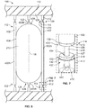
- FIG. 6 is a side view of the tank support assembly 108 according to another example of embodiments according to the present invention.
- multiple tank posts 402 are mounted to the storage tank assembly 112.
- the storage tank assembly 112 is elongated along the height axis 118 and the tank posts 402 are oriented parallel to the height axis 118.
- the tank posts 402 are mounted to an exterior tank surface 404 of the storage tank assembly 112, via welding, fasteners, straps, or the like, such that the tank posts 402 are rigidly secured in place relative to the storage tank assembly 112.
- the tank posts 402 extend beyond the tank 210 and define the top and bottom ends 120, 122 of the storage tank assembly 112.
- the storage tank assembly 112 shows three tank posts 402, including two fully-visible tank posts 402A and one tank post 402B which is partially obscured by the tank 210 as it is positioned behind (e.g., into the page) the tank 210.
- the storage tank assembly 112 optionally may include additional tank posts 402, such as a one on the front of the tank 210, opposite the tank post 402 which is partially obscured by the tank 210.
- the tank posts 402 of the storage tank assembly 112 are coupled to the vehicle structure 110 and associated structure posts 412 thereof via pins 410.
- the pins 410 connect the tank posts 402 of the tank 112 to corresponding structure posts 412 of the vehicle structure 110.
- the structure posts 412 are mounted to the walls 126 above and below the storage tank assembly 112.
- the structure posts 412 are collinear with the corresponding tank posts 402 of the tank 112.
- the pins 410 are optionally affixed to or an integral part of either the tank posts 402 or the structure posts 412.
- the pin 410 is secured or affixed to the tank post 402, and the structure post 412 defines a pin hole (not shown) to receive the pin 410.
- This orientation could be reversed in an alternative example such that the pin 410 is affixed to the structure post 412 and the tank post 402 would define a pin hole through which the pin 410 protrudes.
- the magnetic support system 114 vertically supports the storage tank assembly 112 along the height axis 118 between the walls 126 of vehicle structure 110.
- the magnetic support system 114 is mounted to the tank posts 402 of the storage tank assembly 112 and the structure posts 412 of the vehicle structure 110.
- a tank magnet 130 is affixed to each end of each tank post 402
- a structure magnet 132 is affixed to the end of each structure post 412.
- the tank magnets 130 mounted to the tank posts 402 at the top end 120 of the storage tank assembly 112 represent top magnets
- the tank magnets 130 mounted to the tank posts 402 at the bottom end 122 represent bottom magnets.
- FIG 7 is a close-up perspective view of a portion of the tank support assembly 108 of Figure 6 showing one of the tank posts 402 of the storage tank assembly 112, one of the structure posts 412 of the vehicle structure 110, and the pin 410 that connects the two posts 402, 412.
- the tank magnets 130 and the structure magnets 132 of the magnetic support system 114 may be permanent magnets with like poles facing each other such that the magnets 130, 132 repel.
- the tank magnets 130 and the corresponding structure magnets 132 define matched pairs 420.
- the tank magnet 130 of each pair 420 is mounted to the tank post 402, and the structure magnet 132 of the pair 420 is mounted to the structure post 412.
- the pin 410 extends through both magnets 130, 132.
- the pin 410 is fixedly secured to the tank post 402.
- the pin 410 extends into the pin hole in the structure post 412.
- the pin 410 can move relative to the structure magnet 132 and the structure post 412 through an opening 434 in the magnet 132, in and out of the pin hole of the structure post 412.
- the pin 410 can axially move with the tank post 402 and the tank magnet 130 relative to the structure post 412 and the structure magnet 132.
- the magnets 130, 132 in the matched pairs 420 are spring magnets 418.
- the spring magnets 418 in each pair 420 are permanent magnets that repel when spaced apart less than an equilibrium distance and attract when spaced apart farther than the equilibrium distance.
- the spring magnets 418 may have multiple magnetic poles on a single face.
- the spring magnets 418 may be Polymagnets®, which is a trademark of Correlated Magnetics Research, LLC.
- the length of the equilibrium distance may depend on the size of the magnets, the arrangement of the poles along the magnets, and the materials of the magnets. In a non-limiting example, the equilibrium distance may be a value that is between about 1 mm and about 10 mm, such as about 5 mm.
- a value prefaced by the term "about” includes values that are within a threshold of that value, such as within 1%, 5%, of 10% of that value.
- the tank magnet 130 mounted to the tank post 402 may be located at the equilibrium distance from the structure magnet 132 mounted to the structure post 412 in the position illustrated in Figure 7 .
- the passive repulsive magnetic forces between the magnetic pairs 420 affixed to the ends of the tank posts 402 and the structure posts 412 suspend the storage tank assembly 112 between the vehicle structure 110 located above and below.
- the tank magnet 130 is mounted to an end wall 426 of the tank post 402, and the structure magnet 132 is mounted to an end wall 427 of the structure post 412.
- the structure post 412 is at least partially hollow, and a damper 222 is fixedly mounted within a cavity 432 in the structure post 412.
- the pin 410 extends into the cavity 432 of the structure post 412 and engages the damper 222.
- the damper 222 reduces vibration and slows movement of the pin 410 (and the storage tank assembly 112 coupled thereto) relative to the vehicle structure 110.
- the pins 410 of the tank support assembly 108 provide lateral, longitudinal, and rotational support for the storage tank assembly 112.
- the pin 410 affixed to the tank post 402 may mechanically engage the damper 222 to prevent rotation, tilt, and translation in directions other than the axial direction parallel to the height axis 118.
- the pins 410 may be composed of thermally insulative material, may be limited in number, and/or may have small contact areas with the posts 402 or 412 to substantially reduce thermal conduction from the vehicle structure 110 to the storage tank assembly 112 relative to known tank support systems.
- additional tank and/or structural magnets 130, 132 may be affixed to the tank post 402, the structural post 412 and/or the pin 410, thereby increasing the passive repulsive magnetic forces that suspend the storage tank assembly 112 relative to the vehicle structure 110.
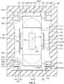
- FIG 8 is a side view of another example of embodiments according to the present invention of the tank support assembly 108.
- the magnetic support system 114 fully structurally supports the storage tank assembly 112 without mechanical engagement between the storage tank assembly 112 and the vehicle structure 110.
- the storage tank assembly 112 is supported without forming any thermal conduction paths from the vehicle structure 110 to the storage tank assembly 112.
- the tank magnets 130 of the magnetic support system 114 include permanent magnets that are mounted are various locations along the storage tank assembly 112.
- the tank magnets 130 include a top tank magnet 130A at the top end 120 and a bottom tank magnet 130B at the bottom end 122.
- the tank magnets 130 are also mounted on a front area 602 of the storage tank assembly 112, on a back area (not shown) of the storage tank assembly 112 opposite the front area 602, on a left area 604 of the storage tank assembly 112, and on a right area 606 of the storage tank assembly 112 opposite the left area 604.
- the front area 602, the back area, the left area 604, and the right area 606 are located between the top and bottom ends 120, 122 along the middle region 214 of the storage tank assembly 112.
- the structure magnets 132 mounted to the vehicle structure 110 include diamagnets 610 that are located at corresponding positions across from the tank magnets 130.
- the diamagnets 610 are configured to provide restoring forces for stabilizing the storage tank assembly 112 relative to the vehicle structure 110.
- Diamagnets e.g., diamagnetic materials
- Diamagnetic materials include pyrolytic graphite, bismuth, copper, or the like.
- the diamagnets 610 interact with the tank magnets 130 to constrain one or more of lateral, longitudinal, or rotational movement of the storage tank assembly 112 relative to the vehicle structure 110.
- a left diamagnet 610A repels the tank magnet 130 mounted along the left area 604
- a right diamagnet 610B repels the tank magnet mounted along the right area 606 to laterally support the tank 112.
- a top diamagnet 610C repels the top tank magnet 130A
- a bottom diamagnet 610D repels the bottom tank magnet 130B to vertically support the tank 112 along the height axis 118.
- the diamagnets 610 may include front and back diamagnets that repel the tank magnet 130 at the front area 602 and the tank magnet at the back area.
- at least some of these diamagnets 610A-D mounted to the vehicle structure 110 may be permanent magnets instead of diamagnets.
- the passive repulsive forces between the tank magnets 130 and the structure magnets 132 may fully suspend the storage tank assembly 112 such that a gap 612 is defined between an outer surface 613 of the storage tank assembly 112 and the vehicle structure 110 without mechanical engagement across the gap 612.
- the outer surface 613 defines an outer perimeter of the storage tank assembly 112.
- the tank magnets 130 may not engage the corresponding structure magnets 132 across the gap 612, such that the gap 612 is continuous and unbroken along the perimeter of the storage tank assembly 112. Due to the stabilization provided by the diamagnets, the magnetic support system 114 is able to fully suspend the storage tank assembly 112 without the use of mechanical struts to provide a mechanical tether between the storage tank assembly 112 and the vehicle structure 110.
- the diamagnets may allow for complete suspension of the storage tank assembly 112 (i.e. no mechanical engagement between the storage tank assembly 112 and the vehicle structure 110) without refuting or breaking Earnshaw's theorem.
- one or more struts may be added to the tank support assembly 108 in the illustrated example to provide additional stabilization and physical constraints.
- the storage tank assembly 112 also includes arms 620 that extend laterally outward.
- the arms 620 have strip magnets 510 or other permanent magnets mounted to the distal ends thereof.
- the strip magnets 510 are permanent magnets that have multiple segments with alternating polarity along lengths thereof. For example, along a single face the strip magnet 510 may include multiple north polarity segments interspersed with south polarity segments.
- the vehicle structure 110 includes multiple magnetic stack-ups 622 that interact with the strip magnets 510 on the arms 620. Each stack-up 622 includes multiple magnets.
- the stack-ups 622 may each have a strip magnet 510 and two diamagnets 610 mounted to the vehicle structure 110.
- One of the diamagnets 610 is disposed between the two strip magnets 510.
- the other diamagnet 610 is located on the other side of the tank-mounted strip magnet 510 such that the diamagnets 610 are disposed on opposite sides of the tank-mounted strip magnet 510.
- the magnets 510, 610 of the stack-up 622 may be mounted to the vehicle structure 110 via extensions 624.
- the magnets 510, 610 of the stack-ups 622 interact to balance the storage tank assembly 112 and to resist rotation of the storage tank assembly 112 relative to the vehicle structure 110.
- each strip magnet 510 on the storage tank assembly 112 may interact with a corresponding strip magnet 510 of a magnetic stack-up 622 of the vehicle structure 110 to define a matched pair 626.
- the alternating north polarity segments and south polarity segments along each of the strip magnets 510 in the matched pair 626 may align in a specific configuration based on attractive forces and repulsive forces, restricting shear movement of the two strip magnets 510 relative to each other.
- the strip magnets 510 restrain translational and rotational movement of the storage tank assembly 112 relative to the vehicle structure 110. For example, based on the orientation of the strip magnets 510, rotation of the storage tank assembly 112 about the height axis 118 would apply shear forces on the strip magnets 510 on the matched pairs 626, to which the strip magnets 510 would oppose.
- FIG 9 is a side view of a top portion of the tank support assembly 108 according to another example of embodiments according to the present invention.
- the storage tank assembly 112 includes at least three tank posts 402 fixedly mounted to the tank 210. Two additional tank posts 402 are required in the illustrated example that are not shown in Figure 9 , which are in front of (e.g., out of the page) and behind (e.g., into the page) the storage tank assembly 112.
- the magnetic support system 114 includes tank magnets 130 mounted on distal ends 704 of the tank posts 402.
- the tank magnets 130 are permanent magnets.
- the magnetic support system 114 also includes several diamagnets 610 and Halbach cylinders 706 that act as the structure magnets 132 shown in previous examples.
- the Halbach cylinders 706 are cylindrical structures that have an arrangement of permanent magnets.
- the arrangement of permanent magnets within the cylinder augments the magnetic field such that a near-uniform magnetic field is generated inside the cylinder.
- Each magnetic subsystem 710 includes two diamagnets 610 extending into an interior region 712 of one Halbach cylinder 706.
- Each magnetic subsystem 710 also includes at least one tank magnet 130 extending into the interior region 712 of the Halbach cylinder 706 and located between the two diamagnets 610.
- the tank magnet 130 does not mechanically engage the diamagnets 610 or the Halbach cylinder 706.
- the Halbach cylinder 706 creates a uniform magnetic field which interacts with the tank magnet 130 to provide an inward repulsive force in a direction perpendicular to the height axis 118 of the storage tank assembly 112.
- the magnetic subsystems 710 shown in Figure 9 may support and balance lateral movement of the tank 112 relative to the vehicle structure 110.
- the Halbach cylinders 706 and the diamagnets 610 are suspended from the wall 126 of the vehicle structure 110 towards the storage tank assembly 112, but may be mounted on or recessed within the wall 126 in an alternative example.
- Two magnetic subsystems 710 are shown in Figure 9 and two magnetic subsystems 710 are not shown, including one in front of (e.g., out of the page) and one behind (e.g., into the page) the storage tank assembly 112.
- the magnetic subsystems 710, tank posts 402, and storage tank assembly 112 are mirrored across a symmetry plane.
- the tank support assembly 108 may include any number of subsystems 710 greater than or equal to six, located at both ends of each corresponding tank post 402.
- the storage tank assembly 112 includes a mechanical strut 228 that extends from the tank 210 to the wall 126 of the vehicle structure 110.
- the strut 228 may at least partially vertically support the storage tank assembly 112 in a direction parallel to the height axis 118, and may restrict rotational motion of the tank 112 about the height axis 118.
- the mechanical strut 228 may optionally be mirrored across a symmetry plane.
- the storage tank assembly 112 may include top and bottom tank magnets and associated structure magnets similar to the tank magnets 130A, 130B and the structure magnets 132A, 132B shown in Figure 2 instead of, or in addition to, the mechanical strut 228.
- Figure 10 is a bottom-up view through a cross-section of the mechanical strut 228 shown in Figure 9 which extends from the storage tank assembly 112 to the vehicle structure 110.
- the mechanical strut 228 is cylindrical with a circular cross-sectional shape, although the strut 228 may have other cross-sectional shapes in other examples.
- the strut 228 is connected to four arms 720 that extend radially outward from the strut 228.
- the four arms 720 are spaced apart from each other around the perimeter of the strut 228 at 90° intervals.
- the arms 720 extend into corresponding recesses 722 in the vehicle structure 110.
- Each of the arms 720 is affixed with two dampers 222, such as dashpots or the like, which engage the vehicle structure 110 at side walls 724 of the recesses 722 to dampen motion of the mechanical strut 228 relative to the vehicle structure 110.
- the dampers 222 on the arms 720 dampen and restrict motion along directions perpendicular to the long axis of the strut 228 (e.g., perpendicular to the height axis 118 shown in Figure 9 ).
- the combination of all four arms 720 and all eight dampers 222 dampens and restricts the motion of the mechanical strut 228 (and the storage tank assembly 112 attached thereto) in the up-down and left-right directions in the orientation shown in Figure 10 , which corresponds to the front-back and left-right directions relative to the orientation depicted in Figure 9 .
- the arms 720 and the dampers 222 also restrict rotation of the mechanical strut 228 and the storage tank assembly 112 about the height axis 118.
- Each end of the dampers 222 may be affixed to rotating pins or bearings (not shown), which allow the dampers 222 to pivot without damaging the dampers 222 in response to the mechanical strut 228 moving perpendicular to a long axis of the respective damper 222.
- sizes of the components and spaces in Figure 10 are for descriptive purposes and visual clarity, and may not represent the actual sizes in a physical manifestation of the example.
- the gaps defined by the vehicle structure 110 surrounding the strut 228 and the arms 720 in Figure 10 may be greater than in a physical manifestation.
- FIG 11 is a flow chart of a method 800 for supporting a storage tank assembly in a vehicle, according to an example of embodiments according to the present invention illustrated in the present disclosure.
- the method 800 begins at 802, at which a storage tank assembly 112 attached to vehicle structure 110 of a vehicle 100 is loaded with a cryogenic fluid.
- the storage tank assembly 112 is attached to the vehicle structure with mechanical struts 228, frangible mechanical elements and/or separable (e.g., detachable) mechanical elements.
- Step 802 may be conducted in a launch vehicle prior to launch or on a vehicle already in a microgravity environment.
- the method 800 includes removing any frangible and/or separable mechanical elements used to secure the storage tank assembly 112 to the vehicle structure 110 during launch, powered propulsion and/or vibration events. Any mechanical struts 228 attaching the storage tank assembly 112 to the vehicle structure 110 that are components of a magnetic support system 114 are left intact.
- the magnetic support system 114 includes tank magnets 130 affixed to the storage tank assembly 112 and structure magnets 132 affixed to the vehicle structure 110.
- the tank magnets 130 interact with the structure magnets 132 to passively provide repulsive magnetic forces that suspend the storage tank assembly 112 relative to the vehicle structure 110 without the tank magnets 130 mechanically engaging the structure magnets 132.
- At least some of the tank magnets 130 and/or structure magnets 132 are permanent magnets with ferromagnetic properties.
- the storage tank assembly 112 may be stabilized relative to the vehicle structure 110 via diamagnets 610 and/or mechanical struts 228.
- the stabilization may be provided by diamagnets 610 alone, mechanical struts 228 alone, or both diamagnets 610 and mechanical struts 228.
- the diamagnets 610 provide restoring forces that stabilize the storage tank assembly 112 in a steady state position within the magnetic field.
- the diamagnets 610 may be affixed to the storage tank assembly 112 and/or to the vehicle structure 110.
- the mechanical struts 228 extend across a gap 140 between the storage tank assembly 112 and the vehicle structure 110 to mechanically constrain and tether the storage tank assembly 112 in position relative to the vehicle structure 110 to allow the magnetic support system 114 to support and suspend the storage tank assembly 112 without the storage tank assembly 112 moving out of position.
- the method 800 according to the present invention may include fewer mechanical connections between the storage tank assembly 112 and the vehicle structure 110, and any mechanical connections that are present may have smaller surface areas, more thermally insulating materials, and the like, to reduce thermal conductive pathways from the vehicle structure 110 to the storage tank assembly 112.
- the tank support assembly 108 is configured to reduce heat transfer from a vehicle structure to a storage tank containing cryogenic fluid to reduce boil-off of the cryogenic fluid and thereby increase the storage life of the cryogenic fluid.
- the tank support assembly 108 may be installed within vehicles traveling long distances or durations, such as spacecraft traveling in microgravity environments.
- the tank support assembly 108 may be passive such that the assembly 108 does not require energy stored within the vehicle to support and suspend the storage tank.
- a tank support assembly (108) for a vehicle (100) comprising:
- the tank magnets (130) and the structure magnets (132) include spring magnets (418) in matched pairs (420) that repel when spaced apart less than an equilibrium distance and attract when spaced apart farther than the equilibrium distance, wherein one magnet in each of the matched pairs represents one of the tank magnets and the other magnet in each of the matched pairs represents one of the structure magnets.
- the magnetic support system (114) fully structurally supports the storage tank assembly (112) without mechanical engagement between the storage tank assembly and the vehicle structure (110).
- tank support assembly (108) optionally further comprising at least one mechanical strut (228) extending from the storage tank assembly (112) to the vehicle structure (110) and coupled to both the storage tank assembly and the vehicle structure, wherein the at least one mechanical strut is non-metallic.
- the structure magnets (132) include diamagnets (610) configured to provide restoring forces for stabilizing the storage tank assembly (112) relative to the vehicle structure (110).
- the diamagnets (610) include a pair of diamagnets disposed within a Halbach cylinder (706), wherein one of the tank magnets (130) is affixed to the storage tank assembly (112) via a tank post (402) that extends from the storage tank assembly, the tank magnet on the tank post extending into the Halbach cylinder between the pair of diamagnets.
- the tank magnets (130) include strip magnets (510) having multiple segments with alternating polarity along lengths of the strip magnets
- the structure magnets (132) include strip magnets (510) that magnetically interact with the strip magnets of the tank magnets in matched pairs (626) to restrain translational and rotational movement of the storage tank assembly (112) relative to the vehicle structure (110) by maintaining alignment between the strip magnets in each of the matched pairs.
- the tank magnets (130) include a top magnet (130A) affixed along a top end (120) of the storage tank assembly (112) and a bottom magnet (130B) affixed along a bottom end (122) of the storage tank assembly that is opposite the top end, wherein the top and bottom magnets are permanent magnets that repel from corresponding structure magnets (132A, 132B) located above the top magnet and below the bottom magnet, respectively, to vertically support and suspend the storage tank assembly.
- the storage tank assembly (112) has a tank (210) in a toroid shape that defines a central cavity (302), the vehicle structure (110) including a central column (306) extending from a first end (308) of the central column above the top end (120) of the storage tank assembly to a second end (310) of the central column below the bottom end (122) of the storage tank assembly, the central column extending through the central cavity of the tank.
- the storage tank assembly (112) includes a tank (210) and one or more tank skirts (212) that engage and surround the tank, wherein at least some of the tank magnets (130) are mounted on the one or more tank skirts.
- the tank magnets are mounted on a front area of the storage tank assembly, a back area of the storage tank assembly opposite the front area, a left area of the storage tank assembly, and a right area of the storage tank assembly opposite the left area, wherein the front, back, left and right areas are located between the top and bottom ends of the storage tank assembly.
- the storage tank assembly has a tank in a toroid shape that defines a central cavity, the vehicle structure including a column extending from a first end of the column above the top end of the storage tank assembly to a second end of the column below the bottom end of the storage tank assembly, the column extending through the central cavity of the tank.
- the structure magnets include diamagnets, the diamagnets interacting with at least some of the tank magnets affixed to a middle region of the storage tank assembly located between the top and bottom ends thereof to constrain one or more of lateral, longitudinal, and rotational movement of the storage tank assembly relative to the vehicle structure.
- the structure magnets include diamagnets that interact with at least some of the tank magnets to stabilize the storage tank assembly such that the passive repulsive magnetic forces between the tank magnets and the structure magnets fully suspend the storage tank assembly without mechanical engagement.
- the tank support assembly further comprises a mechanical strut extending from the storage tank assembly to the vehicle structure, the mechanical strut being non-metallic and coupled to the storage tank assembly along a middle region thereof located between the top and bottom ends, wherein the mechanical strut is configured to constrain one or more of lateral, longitudinal, and rotational movement of the storage tank assembly relative to the vehicle structure.
- the top and bottom magnets of the tank magnets are spring magnets that form matched pairs with corresponding spring magnets of the structure magnets, each of the matched pairs configured to repel when spaced apart less than an equilibrium distance and attract when spaced apart farther than the equilibrium distance.
- the present invention also relates to method for supporting a storage tank assembly (112) in a vehicle (100).
- the method comprises:
- the method further comprises stabilizing the suspended storage tank assembly (112) in a steady state position relative to the vehicle structure (110) via at least one of diamagnets (610) and mechanical struts (228).
- the method further comprises removing frangible mechanical elements used to secure the storage tank assembly (112) to the vehicle structure (110) during launch of the vehicle (100).
- a structure, limitation, or element that is "configured to” perform a task or operation is particularly structurally formed, constructed, or adapted in a manner corresponding to the task or operation.
- an object that is merely capable of being modified to perform the task or operation is not “configured to” perform the task or operation as used herein.
Landscapes
- Engineering & Computer Science (AREA)
- General Engineering & Computer Science (AREA)
- Remote Sensing (AREA)
- Aviation & Aerospace Engineering (AREA)
- Mechanical Engineering (AREA)
- Physics & Mathematics (AREA)
- Chemical & Material Sciences (AREA)
- Combustion & Propulsion (AREA)
- Power Engineering (AREA)
- Electromagnetism (AREA)
- Life Sciences & Earth Sciences (AREA)
- Environmental Sciences (AREA)
- General Health & Medical Sciences (AREA)
- Toxicology (AREA)
- Environmental & Geological Engineering (AREA)
- Biodiversity & Conservation Biology (AREA)
- Health & Medical Sciences (AREA)
- Thermal Sciences (AREA)
- Filling Or Discharging Of Gas Storage Vessels (AREA)
Abstract
Description
- Aspects of the present disclosure generally relate to assemblies within vehicles that support storage tanks, such as cryogenic storage tanks within spacecraft.
- Some vehicles transport very cold cryogenic fluids, such as liquid hydrogen, within storage tanks. The vehicles may be spacecraft that travel within microgravity environments within space. The cryogenic fluids may be used for propellants (e.g., rocket fuel) and/or heating and cooling systems for sensitive electronic instruments (and/or other systems) onboard the vehicle carrying the storage tank. Alternatively, the vehicle carrying the storage tank may supply the cryogenic fluids to another vehicle or station.
- Cryogenic fluids are difficult to store for long durations because of a process known as boil-off. Heat transfer into the tanks causes the liquid to vaporize into a gas, thereby increasing the pressure of the tank. The excess gas must be dumped from the tank to avoid over-pressurization and thus usable fluid is lost over time. Some of the heat at the storage tank may be received via solar radiation that impinges upon the outer surfaces of the vehicle and conductively transfers through vehicle structures to the tank. Additional heat sources may include the electronics (e.g., avionics) onboard the vehicle, such as computing devices and sensors, and the propulsion system. For example, when rocket thrusters are activated, some heat may be conductively conveyed along vehicle structures to the tank. Due to boil-off caused by conductive heat transfer, cryogenic fluids stored according to known systems are not able to be stored for sufficient durations to enable long trips (e.g., space missions). For example, known systems are not able to store cryogenic fluids on vehicles for more than a day or so, substantially restricting the duration and distance of available trips when transporting cryogenic fluids.
- It is with respect to these and other considerations that the disclosure made herein is presented.
- Certain examples of the present disclosure provide a tank support assembly for a vehicle that includes a vehicle structure and a storage tank assembly. In one embodiment the storage tank assembly is held in place relative to the vehicle structure via a magnetic support system. The magnetic support system includes tank magnets affixed to the storage tank assembly and structure magnets affixed to the vehicle structure. The tank magnets interact with the structure magnets to passively provide repulsive magnetic forces that constrain movement of the storage tank assembly relative to the vehicle structure without the tank magnets mechanically engaging the structure magnets.
- Certain examples of the present disclosure provide a tank support assembly for a vehicle that includes a vehicle structure and a storage tank assembly. In one embodiment the vehicle structure includes a plurality of structure magnets affixed thereto. The storage tank assembly is oriented along a height axis between top end thereof and a bottom end thereof that is opposite the top end. The storage tank assembly includes a plurality of tank magnets affixed thereto. The tank magnets include a top magnet affixed along the top end of the storage tank assembly and a bottom magnet affixed along the bottom end of the storage tank assembly. The top magnet and the bottom magnet interact with corresponding structure magnets located above and below the top and bottom ends of the storage tank assembly, respectively, to passively provide repulsive magnetic forces that vertically support and suspend the storage tank assembly along the height axis relative to the vehicle structure without the tank magnets mechanically engaging the structure magnets.
- The present invention also relates to a vehicle, such as a spacecraft, including a tank support assembly according to an embodiment of the present invention.
- Certain examples of the present disclosure provide in an embodiment a method for supporting a storage tank assembly in a vehicle. The method includes loading cryogenic fluid into a storage tank assembly within a vehicle structure of a vehicle, and suspending the storage tank assembly relative to the vehicle structure via a magnetic support system. The magnetic support system includes tank magnets affixed to the storage tank assembly and structure magnets affixed to the vehicle structure. The tank magnets interact with the structure magnets to passively provide repulsive magnetic forces that suspend the storage tank assembly relative to the vehicle structure without the tank magnets mechanically engaging the structure magnets.
- These and other features, aspects, and advantages of the present disclosure will become better understood when the following detailed description is read with reference to the accompanying drawings in which like numerals represent like parts throughout the drawings, wherein:
-
Figure 1 is a perspective view of a vehicle according to an example of the present disclosure. -
Figure 2 is a side view of a tank support assembly of the vehicle according to an example of the present disclosure. -
Figure 3 is a perspective view of a tank of the tank support assembly according to another example. -
Figure 4 is a side view of the tank support assembly according to an example that utilizes the tank shown inFigure 3 . -
Figure 5 is a side view of an optional variation of the tank support assembly shown inFigure 4 . -
Figure 6 is a side view of the tank support assembly according to another example. -
Figure 7 is a close-up perspective view of a portion of the tank support assembly ofFigure 6 showing a post of the storage tank assembly, a post of a vehicle structure, and a pin that connects the two posts. -
Figure 8 is a side view of another example of the tank support assembly. -
Figure 9 is a side view of a top portion of the tank support assembly according to another example. -
Figure 10 is a bottom-up view through a cross-section of a mechanical strut shown inFigure 9 which extends from the storage tank assembly to the vehicle structure. -
Figure 11 is a flow chart of a method for supporting a storage tank assembly in a vehicle according to an example. - The foregoing summary, as well as the following detailed description of certain examples will be better understood when read in conjunction with the appended drawings. As used herein, an element or step recited in the singular and preceded by the word "a" or "an" should be understood as not necessarily excluding the plural of the elements or steps. Further, references to "one example" are not intended to be interpreted as excluding the existence of additional examples that also incorporate the recited features. Moreover, unless explicitly stated to the contrary, examples "comprising" or "having" an element or a plurality of elements having a particular condition may include additional elements not having that condition.
- A system or assembly according to an embodiment of the invention reduces heat transfer from a vehicle structure to a storage tank containing cryogenic fluid to reduce boil-off of the cryogenic fluid and thereby increase the storage life of the cryogenic fluid. Preferably, such a system or assembly would be passive and not require energy stored within the vehicle, such as through active cooling of the storage tank or active support of the storage tank using electromagnets.
- With those effects in mind, certain examples of embodiments according to the present invention illustrated in the present disclosure provide a tank support assembly that reduces thermal conduction paths to cryogenic storage tanks on vehicles operating in microgravity environments via utilizing magnetic materials. The vehicles may be manned or unmanned spacecraft, satellites, space stations, or the like. The magnetic materials constrain the tank to the vehicle while significantly reducing or eliminating the structural linkages between the tank and the vehicle. Reducing or eliminating the structural linkages reduces conductive heat transfer to the tank from heat sources like the sun, on-board electronics, and propulsion systems. The reduction in heat transfer to the tank decreases boil-off of the cryogenic fluid within the tank, increasing the feasibility of using cryogenic fluids for long duration space missions.
- Certain examples of embodiments according to the present invention provide a tank support assembly for a vehicle that includes a vehicle structure and a storage tank assembly. The storage tank assembly is held in place relative to the vehicle structure via a magnetic support system. The magnetic support system includes tank magnets affixed to the storage tank assembly and structure magnets affixed to the vehicle structure. The tank magnets and structure magnets include permanent magnets (i.e. materials which have strong ferromagnetic properties) and/or diamagnets (i.e. materials which have strong diamagnetic properties). The tank magnets interact with the structure magnets to passively provide repulsive magnetic forces that constrain movement of the storage tank assembly relative to the vehicle structure in a microgravity environment without the tank magnets mechanically engaging the structure magnets.
- The tank support assembly of embodiments according to the present invention includes one or more diamagnets and/or mechanical support struts to stabilize the storage tank assembly relative to the vehicle structure. The mechanical struts tether the storage tank assembly to the vehicle structure. It is known that permanent magnets alone are not sufficient to stabilize the storage tank assembly, as described in Earnshaw's Theorem. For example, the tank support assembly in various examples described herein may include permanent magnets with one or more mechanical struts, permanent magnets with diamagnets, or permanent magnets with both diamagnets and one or more mechanical struts.
- The storage tank assembly may contain a cryogenic fluid, such as liquid hydrogen, liquid oxygen, or the like. The vehicle within the microgravity environment may be a spacecraft traveling through space. The spacecraft may be in orbit around the Earth or another planet, or located at a stable or partially stable gravitational well known as a Lagrange point.
- The diamagnets described herein are materials with strong diamagnetic properties that repel an external magnetic field to which the materials are exposed, and the extent of repulsion is proportional to the strength of the applied magnetic field. Via this repulsion, the diamagnets passively provide restoring forces to balance and stabilize the storage tank assembly relative to the vehicle structure. The diamagnet may be affixed to the storage tank assembly, representing tank magnets, and/or affixed to the vehicle structure, representing structure magnets. In one or more examples described herein, the repulsive magnetic forces provided by the permanent magnets and the restoring forces provided by the diamagnets may fully suspend the storage tank assembly relative to the vehicle structure, at least in microgravity environments where there is no significant gravitational force to withstand. The diamagnets also constrain the storage tank assembly from moving out of position and leaving the vehicle. For example, there may be no mechanical engagement between the storage tank assembly and the vehicle structure, direct or indirect, such that a continuous gap surrounds an outer surface of the storage tank assembly. The full suspension of the storage tank assembly reduces heat transfer to the storage tank assembly by eliminating thermal conduction paths between the vehicle and the storage tank assembly. Reducing heat transfer conserves the cryogenic fluid within the storage tank assembly for longer periods of time, allowing for transporting the cryogenic fluid along longer trips covering greater distances.
- The vehicle in at least one example of embodiments according to the present invention includes one or more mechanical struts that couple the storage tank assembly to the vehicle structure when in the microgravity environment. Unlike known tank support assemblies that utilize mechanical struts to support the entire load of the storage tank assembly, the mechanical struts described in the examples herein are utilized for stabilizing the storage tank assembly that is suspended and constrained from leaving the vehicle by the magnetic support system. As used herein, suspension of the storage tank assembly means that the non-contact repulsive forces provided by the magnetic support system at least partially support the weight of the storage tank assembly relative to the vehicle. The one or more mechanical struts or diamagnets stabilize the suspended storage tank assembly. The mechanical struts utilized in the examples described herein may be fewer, smaller, and/or less robust than the mechanical struts in known tank support assemblies because the mechanical struts described herein support less of the load than the struts in the known tank support assemblies. For example, the mechanical struts described herein may be composed of material that is more thermally insulative (e.g., less thermally conductive) than the known struts, such as fiber-reinforced composites, fiberglass, plastics, or the like instead of metals. Although the use of mechanical struts establishes thermal conduction paths from the vehicle to the storage tank assembly, which could lead to boil-off, the reduced number, size, and thermal conductivity of the mechanical struts relative to the known tank support assemblies may substantially reduce the amount of heat transfer to the storage tank assembly, thereby extending the storage life of the cryogenic fluid.
- One or more examples of embodiments according to the present invention illustrated in the present disclosure utilize permanent magnets, and optionally also diamagnets, to eliminate some or all of the mechanical supports used in known tank support assemblies for in-space operation of spacecraft. The magnets and diamagnets allow the storage tank assembly to achieve stable suspension relative to a vehicle structure surrounding the storage tank assembly. In one or more examples, the magnetic suspension is achieved in microgravity environments, such as in free-fall while the spacecraft is in orbit. The vehicle may have frangible and/or detachable mechanical elements that support and secure the tank during launch and uncouple from the tank upon reaching a microgravity environment. In the microgravity environment, the magnetic support system can meet all loading and vibrational requirements.
- The magnetic support system may include permanent magnets placed at strategic locations on the storage tank assembly that pair with magnets attached to the vehicle structure surrounding the tank to create an unstable equilibrium point at a desired steady state position. Diamagnets and/or minimal mechanical struts provide restoring forces for stabilizing the tank at the steady state position, to achieve a stable equilibrium point. The magnetic support system may be entirely passive, meaning that there is no power requirement to support and suspend the tank. The magnets on the tank interact with the magnets on the vehicle structure to passively provide repulsive magnetic forces that suspend the tank. For example, the magnetic support system may not include electromagnets, superconductors which require active cooling systems, or the like.
- A technical effect of one or more of the examples of the tank support assembly of embodiments according to the present invention described herein is an extended storage life of cryogenic fluids within a storage tank assembly carried by a vehicle in microgravity environments, which enables longer mission durations and farther travel distances. Because there may be less boil-off of the cryogenic fluid, the vehicle may be able to transport more cryogenic fluid to a destination, such as another vehicle or a space station, for a given amount of energy expended during the trip than vehicles utilizing known tank support systems. Another technical effect may include energy conservation because the magnetic support system may be passive, without requiring an energy source to suspend the storage tank assembly. Another technical effect may be a weight savings through the reduction or complete elimination of heavy mechanical struts which would normally be necessary to fully support and suspend the storage tank assembly.
-
Figure 1 is a perspective view of avehicle 100 according to an example of embodiments according to the present invention as illustrated in the present disclosure. Thevehicle 100 is a spacecraft in the illustrated example, and is configured to travel in microgravity environments. As used herein, microgravity environments experience reduced gravitational forces than the gravitational forces experienced on Earth (e.g., at sea level). For example, thevehicle 100 may travel in the microgravity environment of space, such as in orbit around the Earth or another planet. Thevehicle 100 in the illustrated example is a shuttle designed to carry people and cargo, but thevehicle 100 in other examples may be an unmanned vehicle that does not carry people. Thevehicle 100 includes a main body orfuselage 102 andwings 104 extending from thebody 102. Thevehicle 100 carries a payload (e.g., cargo and/or passengers) within one ormore compartments 106 of thebody 102. - The
vehicle 100 includes atank support assembly 108. Thetank support assembly 108 includes avehicle structure 110 and astorage tank assembly 112. Thetank support assembly 108 also includes amagnetic support system 114 that supports and at least partially suspends thestorage tank assembly 112 relative to thevehicle structure 110. A cross-sectional illustration of thetank support assembly 108 is shown inFigure 1 . The illustration inFigure 1 is intended for introducing the components of thetank support assembly 108 and may not necessarily represent the shapes, sizes, and arrangement of the components thereof, which are shown in more detail in the following figures. - The
storage tank assembly 112 is hollow and contains acryogenic fluid 116. Thecryogenic fluid 116 may be a propellant such as liquid hydrogen, liquid oxygen, or the like, stored at a very cold temperature. Thestorage tank assembly 112 may be insulated to reduce heat transfer from outside of thetank 112 into thecryogenic fluid 116. In the illustrated example, thestorage tank assembly 112 is elongated along aheight axis 118 of thestorage tank assembly 112. For example, thestorage tank assembly 112 may be cylindrical and oriented about theheight axis 118. Thestorage tank assembly 112 extends along theheight axis 118 from atop end 120 thereof to abottom end 122 that is opposite thetop end 120. Thestorage tank assembly 112 has one ormore side walls 124 defining a perimeter of thetank 112. Each of the one ormore side walls 124 extends from thetop end 120 to thebottom end 122. For example, when thestorage tank assembly 112 is cylindrical, asingle side wall 124 may define a circumference of thetank 112, although two different portions of theside wall 124 are shown in the illustrated cross-section. - As used herein, relative or spatial terms such as "top," "bottom," "left," "right," "front", "rear", "upper," and "lower" are only used to identify and distinguish the referenced elements and do not necessarily require particular positions or orientations in the surrounding environment of the
tank support assembly 108. For example, it is recognized that thevehicle 100 may rotate in space such that thetop end 120 may be below thebottom end 122 relative to the direction of gravitational force experienced on Earth. The relative or spatial terms are therefore specific to the orientations depicted in the figures. - The
vehicle structure 110 haswalls 126 that at least partially surround thestorage tank assembly 112. Thewalls 126 at least partially define achamber 128 in which thestorage tank assembly 112 is disposed. Thetank support assembly 108 may be located within one of thecompartments 106 of thebody 102, and thevehicle structure 110 may represent part of, or may be attached to, thebody 102. For example, thewalls 126 may be interior walls of thebody 102 that define one of thecompartments 106. The illustrated cross-section shows that thewalls 126 surround thetank 112 above and below the top and bottom ends 120, 122, and on both left and right sides of the one ormore side walls 124. Although not shown, thevehicle structure 110 may also longitudinally surround thetank 112 both in front of (e.g., out of the page) and behind (e.g., into the page) thetank 112. - In
Figure 1 , thevehicle structure 110 is mechanically spaced apart from thetank 112 via agap 140 that fully surrounds thetank 112, such that thestorage tank assembly 112 does not mechanically engage thevehicle structure 110. Thetank 112 is supported and held in place relative to thevehicle structure 110 by themagnetic support system 114. Themagnetic support system 114 includes a plurality of magnets. The magnets include bothtank magnets 130 affixed to thestorage tank assembly 112 andstructure magnets 132 affixed to thevehicle structure 110. Thetank magnets 130 interact with thestructure magnets 132 to passively provide repulsive magnetic forces that constrain movement of thestorage tank assembly 112 relative to thevehicle structure 110 in a microgravity environment without thetank magnets 130 mechanically engaging thestructure magnets 132. At least some of thetank magnets 130 are permanent magnets. Thetank magnets 130 are located at positions that correspond to positions ofstructure magnets 132 to define match or corresponding pairs that repel each other. This repulsion between the pairs ofmagnets tank magnets 130 from mechanically engaging thestructure magnets 132. Thetank magnets 130 in the illustrated example are affixed to thetop end 120, thebottom end 122, and the one ormore side walls 124 of thestorage tank assembly 112. The repulsion between thesetank magnets 130 and the associatedstructure magnets 132 establishes and maintains thegap 140 between thestorage tank assembly 112 and thevehicle structure 110, preventing thermal conduction paths from thevehicle structure 110 to thestorage tank assembly 112. The term "magnets" used herein, unless otherwise specified as permanent magnets or diamagnets, may represent permanent magnets only, diamagnets only, or both permanent magnets and diamagnets. - The
tank support assembly 108 of thevehicle 100 may include one or moremechanical struts 228, such as straps, posts, tubes, chains, or the like, that mechanically connect thestorage tank assembly 112 to thevehicle structure 110. The one or moremechanical struts 228 are utilized to stabilize the passive magnetic repulsive forces, not to support the full load of thestorage tank assembly 112. Suchmechanical struts 228 may be few in number, small in size and contact area with thetank 112, thermally insulative in construction material, and/or the like to reduce thermal conduction from thevehicle structure 110 to thetank 112 across the struts. For example, only onemechanical strut 228 is shown inFigure 1 . Alternatively, diamagnets may be used in addition to or instead ofmechanical struts 228 to provide stability to the suspendedstorage tank assembly 112. -
Figure 2 is a side view of thetank support assembly 108 according to an example of embodiments according to the present invention as illustrated in the present disclosure. In the illustrated example, thestorage tank assembly 112 includestank magnets 130 along the top and bottom ends 120, 122 thereof. For example, atop tank magnet 130A is a fixed along thetop end 120, and abottom tank magnet 130B is a fixed along thebottom end 122. The top andbottom tank magnets top magnet 130A and bottom magnet 103B, respectively. The top andbottom magnets 103A, 130B are permanent magnets that have ferromagnetic properties. For example, themagnets - The top and
bottom magnets corresponding structure magnets 132 located above and below thestorage tank assembly 112 to vertically support and suspend thestorage tank assembly 112 along theheight axis 118. Thetop magnet 130A repels from anupper structure magnet 132A located above thetop end 120 of thetank 112. Thetop magnet 130A may repel from theupper structure magnet 132A due to like poles facing each other (e.g., north-north or south-south). Thebottom magnet 130B repels from alower structure magnet 132B located below thebottom end 122 of thetank 112. The interactions between thetop magnet 130A and theupper structure magnet 132A, and between thebottom magnet 130B and thelower structure magnet 132B, passively provide repulsive magnetic forces that vertically support and suspend thestorage tank assembly 112 relative to thevehicle structure 110 in a microgravity environment. Due to the repulsive forces, thetop magnet 130A may not mechanically engage theupper structure magnet 132A, and thebottom magnet 130B may not mechanically engage thelower structure magnet 132B. - The
storage tank assembly 112 may include atank 210 and one or more tank skirts 212. Thetank 210 of thestorage tank assembly 112 contains the cryogenic fluid 116 (shown inFigure 1 ) therein. In the illustrated example, thetank 210 is pill-shaped with rounded dome-shaped ends 236 and is elongated along theheight axis 118. The one ormore tank skirts 212 surround the dome-shaped ends 236. The tank skirts 212 extend from thetank 210 and define thetop end 120 and thebottom end 122 of thestorage tank assembly 112. Thetank magnets 130 in the illustrated example include thetop magnet 130A mounted on thetop end 120 of thestorage tank assembly 112 and thebottom magnet 130B mounted on thebottom end 122 of thestorage tank assembly 112. For example, the tank skirts 212 include anupper tank skirt 212A that defines thetop end 120, and alower tank skirt 212B that defines thebottom end 122. Thetop magnet 130A is mounted on theupper tank skirt 212A, and thebottom magnet 130B is mounted on thelower tank skirt 212B. The upper andlower tank skirts middle region 214 of thestorage tank assembly 112. Alternatively, the upper andlower tank skirts middle region 214. Although not shown, the top andbottom magnets storage tank assembly 112. - The upper and
lower structure magnets structure magnets corresponding tank magnets structure magnets respective walls 126 of thevehicle structure 110. For example, springs 220 anddampers 222 may be disposed between thestructure magnets corresponding walls 126 of thevehicle structure 110 to enable thestructure magnets storage tank assembly 112 based on the repulsive magnetic forces. Thedampers 222 may be dashpots or other force dampening devices. Thesprings 220 anddampers 222 are optionally embedded withinrecesses 224 in thewalls 126 of thevehicle structure 110. Alternatively, thesprings 220 anddampers 222 may protrude frominterior surfaces 226 of thewalls 126 instead of being recessed from theinterior surfaces 226 within thewalls 126. - In an alternative example of embodiments according to the present invention, the upper and
lower structure magnets - In the illustrated example of embodiments according to the present invention, the
tank support assembly 108 includes at least onemechanical strut 228 that extends from thestorage tank assembly 112 to thevehicle structure 110. Eachmechanical strut 228 is coupled to both thestorage tank assembly 112 and thevehicle structure 110. Two struts 228 are shown inFigure 2 . Thestruts 228 are configured to constrain lateral, longitudinal, and/or rotational movement of thestorage tank assembly 112 relative to thevehicle structure 110. Thestruts 228 havetank interfaces 230 and structure interfaces 232. The tank interfaces 230 are mechanically coupled to theside walls 124 of thestorage tank assembly 112. In the illustrated example, the tank interfaces 230 engage themiddle region 214, but may engage the dome-shaped ends 236 or the tank skirts 212 in another example. The structure interfaces 232 are mechanically coupled to thevehicle structure 110. In the illustrated example, the structure interfaces 232 extend intoslots 234 in thewalls 126 of thevehicle structure 110. Each of the structure interfaces 232 is held between twodampers 222 within thecorresponding slot 234. Theslots 234 allow vertical movement of the struts 228 (e.g., parallel to the height axis 118) with the movement of thestorage tank assembly 112. Thedampers 222 limit or dampen such vertical movement. Thestruts 228 are configured to stabilize and balance thestorage tank assembly 112 that is suspended by themagnetic support system 114. The two illustratedstruts 228 extend laterally left and right of thetank 112. Optionally, one or twoadditional struts 228 may be installed that extend longitudinally forward (e.g., out of the page) and/or backward (e.g., into the page) from thetank 112 to restrain movement or tilt in the forward and backward directions. Thestruts 228 tether thetank 112 to thevehicle structure 110, such that themagnetic support system 114 suspends thetank 112 and constrains thetank 112 from leaving thevehicle 100. - Although the
mechanical struts 228 do provide thermal conductive pathways from thevehicle structure 110 to thestorage tank assembly 112, the amount of heat transfer to thestorage tank assembly 112 is mitigated in several ways. For example, because thestruts 228 are used for stability, and not for supporting the entire load of thestorage tank assembly 112, veryfew struts 228 may be required. The illustrated example may include less than or equal to fourstruts 228, which may be fewer than the number of struts installed in known tank support systems. Furthermore, thestruts 228 may be smaller (e.g., thinner) than the struts used in the known tank support systems for the same reason. Thestruts 228 also may be non-metallic and at least partially composed of thermally insulative materials that hinder thermal conduction. The thermally insulative materials may include fiberglass, fiber-reinforced composites, plastics, or the like. The contact surface areas at the structure interfaces 232 between thestruts 228 and thevehicle structure 110 may be relatively small, further reducing conductive heat transfer between thevehicle structure 110 and thestorage tank assembly 112. Furthermore, the contact surface areas at the structure interfaces 232 can be reduced by using a linear ball bearing or linear rail that allows thestrut 228 to slide up and down within theslot 234 of thevehicle structure 110. Such reduced contact area (e.g., relative to known mechanical strut support systems) is permissible because thestruts 228 do not support the full mass of thetank 112, but rather supplement themagnetic support system 114. - Although not shown in
Figure 2 , themagnetic support system 114 may includeadditional tank magnets 130 that interact withstructure magnets 132 affixed to thevehicle structure 110 along the sides of thetank 112. In an alternative example, at least some of thesetank magnets 130 and/orstructure magnets 132 may be diamagnets that provide stability. The diamagnets may replace themechanical struts 228 shown inFigure 2 to provide stabilized, full suspension of thestorage tank assembly 112. -
Figure 3 is a perspective view of thetank 210 of thestorage tank assembly 112 according to another example of embodiments according to the present invention. Thetank 210 has a toroid shape, and defines acentral cavity 302. For example, thetank 210 has a closed, annular ring shape. Thetank 210 contains cryogenic fluid therein, such that the cryogenic fluid within thetank 210 encircles thecentral cavity 302. -
Figure 4 is a side view of thetank support assembly 108 according to an example of embodiments according to the present invention that utilizes thetank 210 shown inFigure 3 . In the illustrated example, thestorage tank assembly 112 is oriented along atoroid plane 304. Thestorage tank assembly 112 includes thetoroid tank 210 and ahousing member 312 that surrounds and holds thetank 210. Thehousing member 312 defines both thetop end 120 and thebottom end 122 of thestorage tank assembly 112. The top and bottom ends 120, 122 of thehousing member 312 may be planar and oriented parallel to thetoroid plane 304. Thetop tank magnet 130A of thetank magnets 130 is mounted to thetop end 120, and thebottom tank magnet 130B is mounted to thebottom end 122. - In the illustrated example, the
vehicle structure 110 includes acentral column 306 that extends through thecentral cavity 302 of thestorage tank assembly 112. Thecentral column 306 has afirst end 308 above thetop end 120 of thestorage tank assembly 112 and a second end 310 (opposite the first end 308) below thebottom end 122 of thestorage tank assembly 112. The first and second ends 308, 310 are mounted to correspondingwalls 126 of thevehicle structure 110. - The
storage tank assembly 112 is movable relative to thevehicle structure 110 axially along the length of thecentral column 306 based on the passive repulsive magnetic forces provided by themagnetic support system 114. For example, thetop tank magnet 130A repels theupper structure magnet 132A, and thebottom tank magnet 130B repels thelower structure magnet 132B, thereby suspending thestorage tank assembly 112 between thestructure magnets central column 306 and cause thestorage tank assembly 112 to move at least slightly along the length of thecentral column 306. - The
housing member 312 defines acentral channel 314 that aligns with thecentral cavity 302 of thetank 210. Thecentral column 306 extends through thecentral channel 314. Thecentral channel 314 of thehousing member 312 may have a smaller diameter than thecentral cavity 302 of thetank 210, such that aninner surface 316 of thehousing member 312 is radially closer to thecentral column 306 than the proximity of an inner diameter of thetank 210 to thecentral column 306. In the illustrated example, thecentral column 306 includescolumn fingers 318 that project laterally and/or radially from thecentral column 306. Thecolumn fingers 318 may be elongated parallel to thetoroid plane 304 and perpendicular to the axis of thecentral column 306. Thecolumn fingers 318 may engage thehousing member 312 indirectly viadampers 222 disposed between thecolumn fingers 318 and thehousing member 312. The engagement of thecolumn fingers 318 and thehousing member 312, via thedampers 222, stabilize thestorage tank assembly 112 relative to thevehicle structure 110. For example, thetanks magnets structure magnets storage tank assembly 112 may not be able to remain in a stable stationary equilibrium based only on the repulsive magnetic forces provided by these permanent magnets, as described in Earnshaw's theorem. Thecolumn fingers 318 of thecentral column 306 indirectly engage thestorage tank assembly 112 to stabilize thestorage tank assembly 112. Thedampers 222 dampen axial movement of thestorage tank assembly 112 along thecentral column 306 to reduce tilt and vibration. - Although the
tank support assembly 108 ofFigure 4 includes the toroidstorage tank assembly 112 shown inFigure 3 , it is recognized that thestorage tank assembly 112 may have other shapes and still be utilized in the example shown inFigure 4 . For example, thetank 210 of thestorage tank assembly 112 according to an alternative example may be cylindrical and define an opening that extends axially through a height of thetank 210. Thecentral column 306 may extend through the opening of thecylindrical tank 210, similar to how thecentral column 306 extends through thecentral cavity 302 inFigure 4 . -
Figure 5 is a side view of an optional variation of thetank support assembly 108 shown inFigure 4 . Thetank support assembly 108 inFigure 5 includes multiplestorage tank assemblies 112. Thestorage tank assemblies 112 are stacked axially along the length of thecentral column 306 and located between theupper structure magnet 132A and thelower structure magnet 132B of thevehicle structure 110. Twostorage tank assemblies 112 are shown in the illustrated example. Each of thestorage tank assemblies 112 is the same as thestorage tank assembly 112 shown inFigure 4 . For example, a first tank 112A of the twostorage tank assemblies 112 is located between theupper structure magnet 132A and asecond tank 112B of the twostorage tank assemblies 112. Thetop tank magnet 130A of the first tank 112A interacts with and repels theupper structure magnet 132A. Thebottom tank magnet 130B of thesecond tank 112B interacts with and repels thelower structure magnet 132B. Thebottom tank magnet 130B of the first tank 112A interacts with and repels thetop tank magnet 130A of thesecond tank 112B, which maintains a separation distance between the first andsecond tanks 112A, 112B. Although twotanks 112A, 112B are shown in the illustrated example, it is understood that thetank support assembly 108 may include one or more additionalstorage tank assemblies 112 by extending the length of thecentral column 306. -
Figure 6 is a side view of thetank support assembly 108 according to another example of embodiments according to the present invention. In this example,multiple tank posts 402 are mounted to thestorage tank assembly 112. Thestorage tank assembly 112 is elongated along theheight axis 118 and the tank posts 402 are oriented parallel to theheight axis 118. The tank posts 402 are mounted to anexterior tank surface 404 of thestorage tank assembly 112, via welding, fasteners, straps, or the like, such that the tank posts 402 are rigidly secured in place relative to thestorage tank assembly 112. The tank posts 402 extend beyond thetank 210 and define the top and bottom ends 120, 122 of thestorage tank assembly 112. In the illustrated example, thestorage tank assembly 112 shows threetank posts 402, including two fully-visible tank posts 402A and onetank post 402B which is partially obscured by thetank 210 as it is positioned behind (e.g., into the page) thetank 210. Thestorage tank assembly 112 optionally may includeadditional tank posts 402, such as a one on the front of thetank 210, opposite thetank post 402 which is partially obscured by thetank 210. - The tank posts 402 of the
storage tank assembly 112 are coupled to thevehicle structure 110 and associated structure posts 412 thereof via pins 410. In the illustrated example, thepins 410 connect the tank posts 402 of thetank 112 to corresponding structure posts 412 of thevehicle structure 110. The structure posts 412 are mounted to thewalls 126 above and below thestorage tank assembly 112. The structure posts 412 are collinear with thecorresponding tank posts 402 of thetank 112. Thepins 410 are optionally affixed to or an integral part of either the tank posts 402 or the structure posts 412. In the illustrated example shown inFigure 7 , thepin 410 is secured or affixed to thetank post 402, and thestructure post 412 defines a pin hole (not shown) to receive thepin 410. This orientation could be reversed in an alternative example such that thepin 410 is affixed to thestructure post 412 and thetank post 402 would define a pin hole through which thepin 410 protrudes. - In the illustrated example, the
magnetic support system 114 vertically supports thestorage tank assembly 112 along theheight axis 118 between thewalls 126 ofvehicle structure 110. Themagnetic support system 114 is mounted to the tank posts 402 of thestorage tank assembly 112 and the structure posts 412 of thevehicle structure 110. Although not shown inFigure 6 , atank magnet 130 is affixed to each end of eachtank post 402, and astructure magnet 132 is affixed to the end of eachstructure post 412. Thetank magnets 130 mounted to the tank posts 402 at thetop end 120 of thestorage tank assembly 112 represent top magnets, and thetank magnets 130 mounted to the tank posts 402 at thebottom end 122 represent bottom magnets. -
Figure 7 is a close-up perspective view of a portion of thetank support assembly 108 ofFigure 6 showing one of the tank posts 402 of thestorage tank assembly 112, one of the structure posts 412 of thevehicle structure 110, and thepin 410 that connects the twoposts tank magnets 130 and thestructure magnets 132 of themagnetic support system 114 may be permanent magnets with like poles facing each other such that themagnets - The
tank magnets 130 and thecorresponding structure magnets 132 define matchedpairs 420. In the illustrated example, thetank magnet 130 of eachpair 420 is mounted to thetank post 402, and thestructure magnet 132 of thepair 420 is mounted to thestructure post 412. Thepin 410 extends through bothmagnets pin 410 is fixedly secured to thetank post 402. Thepin 410 extends into the pin hole in thestructure post 412. Thepin 410 can move relative to thestructure magnet 132 and thestructure post 412 through anopening 434 in themagnet 132, in and out of the pin hole of thestructure post 412. Thepin 410 can axially move with thetank post 402 and thetank magnet 130 relative to thestructure post 412 and thestructure magnet 132. - In at least one example, the
magnets pairs 420 arespring magnets 418. Thespring magnets 418 in eachpair 420 are permanent magnets that repel when spaced apart less than an equilibrium distance and attract when spaced apart farther than the equilibrium distance. For example, thespring magnets 418 may have multiple magnetic poles on a single face. Optionally, thespring magnets 418 may be Polymagnets®, which is a trademark of Correlated Magnetics Research, LLC. The length of the equilibrium distance may depend on the size of the magnets, the arrangement of the poles along the magnets, and the materials of the magnets. In a non-limiting example, the equilibrium distance may be a value that is between about 1 mm and about 10 mm, such as about 5 mm. As used herein, a value prefaced by the term "about" includes values that are within a threshold of that value, such as within 1%, 5%, of 10% of that value. Thetank magnet 130 mounted to thetank post 402 may be located at the equilibrium distance from thestructure magnet 132 mounted to thestructure post 412 in the position illustrated inFigure 7 . With additional reference toFigure 6 , the passive repulsive magnetic forces between themagnetic pairs 420 affixed to the ends of the tank posts 402 and the structure posts 412 suspend thestorage tank assembly 112 between thevehicle structure 110 located above and below. - In
Figure 7 , thetank magnet 130 is mounted to anend wall 426 of thetank post 402, and thestructure magnet 132 is mounted to anend wall 427 of thestructure post 412. Thestructure post 412 is at least partially hollow, and adamper 222 is fixedly mounted within a cavity 432 in thestructure post 412. Thepin 410 extends into the cavity 432 of thestructure post 412 and engages thedamper 222. Thedamper 222 reduces vibration and slows movement of the pin 410 (and thestorage tank assembly 112 coupled thereto) relative to thevehicle structure 110. Thepins 410 of thetank support assembly 108 provide lateral, longitudinal, and rotational support for thestorage tank assembly 112. For example, thepin 410 affixed to thetank post 402 may mechanically engage thedamper 222 to prevent rotation, tilt, and translation in directions other than the axial direction parallel to theheight axis 118. Thepins 410 may be composed of thermally insulative material, may be limited in number, and/or may have small contact areas with theposts vehicle structure 110 to thestorage tank assembly 112 relative to known tank support systems. - In an alternative example of embodiments according to the present invention, additional tank and/or
structural magnets tank post 402, thestructural post 412 and/or thepin 410, thereby increasing the passive repulsive magnetic forces that suspend thestorage tank assembly 112 relative to thevehicle structure 110. -
Figure 8 is a side view of another example of embodiments according to the present invention of thetank support assembly 108. In the illustrated example, themagnetic support system 114 fully structurally supports thestorage tank assembly 112 without mechanical engagement between thestorage tank assembly 112 and thevehicle structure 110. Thestorage tank assembly 112 is supported without forming any thermal conduction paths from thevehicle structure 110 to thestorage tank assembly 112. Thetank magnets 130 of themagnetic support system 114 include permanent magnets that are mounted are various locations along thestorage tank assembly 112. For example, thetank magnets 130 include atop tank magnet 130A at thetop end 120 and abottom tank magnet 130B at thebottom end 122. Thetank magnets 130 are also mounted on afront area 602 of thestorage tank assembly 112, on a back area (not shown) of thestorage tank assembly 112 opposite thefront area 602, on aleft area 604 of thestorage tank assembly 112, and on aright area 606 of thestorage tank assembly 112 opposite theleft area 604. Thefront area 602, the back area, theleft area 604, and theright area 606 are located between the top and bottom ends 120, 122 along themiddle region 214 of thestorage tank assembly 112. - The
structure magnets 132 mounted to thevehicle structure 110 includediamagnets 610 that are located at corresponding positions across from thetank magnets 130. Thediamagnets 610 are configured to provide restoring forces for stabilizing thestorage tank assembly 112 relative to thevehicle structure 110. Diamagnets (e.g., diamagnetic materials) have diamagnetic properties that repel a magnetic field to which the diamagnets are exposed in proportion to the strength of the magnetic field. Diamagnetic materials include pyrolytic graphite, bismuth, copper, or the like. - The
diamagnets 610 interact with thetank magnets 130 to constrain one or more of lateral, longitudinal, or rotational movement of thestorage tank assembly 112 relative to thevehicle structure 110. For example, aleft diamagnet 610A repels thetank magnet 130 mounted along theleft area 604, and aright diamagnet 610B repels the tank magnet mounted along theright area 606 to laterally support thetank 112. Atop diamagnet 610C repels thetop tank magnet 130A, and abottom diamagnet 610D repels thebottom tank magnet 130B to vertically support thetank 112 along theheight axis 118. Although not shown, thediamagnets 610 may include front and back diamagnets that repel thetank magnet 130 at thefront area 602 and the tank magnet at the back area. In an alternative example, at least some of thesediamagnets 610A-D mounted to thevehicle structure 110 may be permanent magnets instead of diamagnets. - The passive repulsive forces between the
tank magnets 130 and thestructure magnets 132 may fully suspend thestorage tank assembly 112 such that agap 612 is defined between anouter surface 613 of thestorage tank assembly 112 and thevehicle structure 110 without mechanical engagement across thegap 612. Theouter surface 613 defines an outer perimeter of thestorage tank assembly 112. For example, thetank magnets 130 may not engage thecorresponding structure magnets 132 across thegap 612, such that thegap 612 is continuous and unbroken along the perimeter of thestorage tank assembly 112. Due to the stabilization provided by the diamagnets, themagnetic support system 114 is able to fully suspend thestorage tank assembly 112 without the use of mechanical struts to provide a mechanical tether between thestorage tank assembly 112 and thevehicle structure 110. The diamagnets may allow for complete suspension of the storage tank assembly 112 (i.e. no mechanical engagement between thestorage tank assembly 112 and the vehicle structure 110) without refuting or breaking Earnshaw's theorem. Optionally, one or more struts may be added to thetank support assembly 108 in the illustrated example to provide additional stabilization and physical constraints. - In the illustrated example, the
storage tank assembly 112 also includesarms 620 that extend laterally outward. Thearms 620 havestrip magnets 510 or other permanent magnets mounted to the distal ends thereof. Thestrip magnets 510 are permanent magnets that have multiple segments with alternating polarity along lengths thereof. For example, along a single face thestrip magnet 510 may include multiple north polarity segments interspersed with south polarity segments. Thevehicle structure 110 includes multiple magnetic stack-ups 622 that interact with thestrip magnets 510 on thearms 620. Each stack-up 622 includes multiple magnets. For example, the stack-ups 622 may each have astrip magnet 510 and twodiamagnets 610 mounted to thevehicle structure 110. One of thediamagnets 610 is disposed between the twostrip magnets 510. Theother diamagnet 610 is located on the other side of the tank-mountedstrip magnet 510 such that thediamagnets 610 are disposed on opposite sides of the tank-mountedstrip magnet 510. Themagnets vehicle structure 110 viaextensions 624. - The
magnets ups 622 interact to balance thestorage tank assembly 112 and to resist rotation of thestorage tank assembly 112 relative to thevehicle structure 110. For example, eachstrip magnet 510 on thestorage tank assembly 112 may interact with acorresponding strip magnet 510 of a magnetic stack-up 622 of thevehicle structure 110 to define a matchedpair 626. The alternating north polarity segments and south polarity segments along each of thestrip magnets 510 in the matchedpair 626 may align in a specific configuration based on attractive forces and repulsive forces, restricting shear movement of the twostrip magnets 510 relative to each other. By maintaining the alignment between the twostrip magnets 510 in each of the matchedpairs 626, thestrip magnets 510 restrain translational and rotational movement of thestorage tank assembly 112 relative to thevehicle structure 110. For example, based on the orientation of thestrip magnets 510, rotation of thestorage tank assembly 112 about theheight axis 118 would apply shear forces on thestrip magnets 510 on the matchedpairs 626, to which thestrip magnets 510 would oppose. -
Figure 9 is a side view of a top portion of thetank support assembly 108 according to another example of embodiments according to the present invention. In the illustrated example, thestorage tank assembly 112 includes at least threetank posts 402 fixedly mounted to thetank 210. Twoadditional tank posts 402 are required in the illustrated example that are not shown inFigure 9 , which are in front of (e.g., out of the page) and behind (e.g., into the page) thestorage tank assembly 112. Themagnetic support system 114 includestank magnets 130 mounted ondistal ends 704 of the tank posts 402. Thetank magnets 130 are permanent magnets. Themagnetic support system 114 also includesseveral diamagnets 610 and Halbach cylinders 706 that act as thestructure magnets 132 shown in previous examples. The Halbach cylinders 706 are cylindrical structures that have an arrangement of permanent magnets. The arrangement of permanent magnets within the cylinder augments the magnetic field such that a near-uniform magnetic field is generated inside the cylinder. In the illustrated example, all the Halbach cylinders 706 utilize a k=2 pattern with the uniform magnetic field oriented towards a center axis of the storage tank assembly 112 (e.g., parallel to or along the height axis 118). - The
tank magnets 130 andstructure magnets 132 are arranged in severalmagnetic subsystems 710. Eachmagnetic subsystem 710 includes twodiamagnets 610 extending into aninterior region 712 of one Halbach cylinder 706. Eachmagnetic subsystem 710 also includes at least onetank magnet 130 extending into theinterior region 712 of the Halbach cylinder 706 and located between the twodiamagnets 610. Thetank magnet 130 does not mechanically engage thediamagnets 610 or the Halbach cylinder 706. The Halbach cylinder 706 creates a uniform magnetic field which interacts with thetank magnet 130 to provide an inward repulsive force in a direction perpendicular to theheight axis 118 of thestorage tank assembly 112. Coupled with the repulsive force generate by the Halbach cylinder within anothermagnetic subsystem 710 located on the opposite side of thestorage tank assembly 112, an unstable equilibrium point is established. Thediamagnets 610 located on either side of thetank magnet 130 then provide the stabilization force necessary to establish a stable equilibrium point. Thus themagnetic subsystems 710 shown inFigure 9 may support and balance lateral movement of thetank 112 relative to thevehicle structure 110. - In the illustrated example, the Halbach cylinders 706 and the
diamagnets 610 are suspended from thewall 126 of thevehicle structure 110 towards thestorage tank assembly 112, but may be mounted on or recessed within thewall 126 in an alternative example. Twomagnetic subsystems 710 are shown inFigure 9 and twomagnetic subsystems 710 are not shown, including one in front of (e.g., out of the page) and one behind (e.g., into the page) thestorage tank assembly 112. Themagnetic subsystems 710,tank posts 402, andstorage tank assembly 112 are mirrored across a symmetry plane. Thetank support assembly 108 may include any number ofsubsystems 710 greater than or equal to six, located at both ends of eachcorresponding tank post 402. - In the illustrated example, the
storage tank assembly 112 includes amechanical strut 228 that extends from thetank 210 to thewall 126 of thevehicle structure 110. Thestrut 228 may at least partially vertically support thestorage tank assembly 112 in a direction parallel to theheight axis 118, and may restrict rotational motion of thetank 112 about theheight axis 118. Themechanical strut 228 may optionally be mirrored across a symmetry plane. In an alternative example, thestorage tank assembly 112 may include top and bottom tank magnets and associated structure magnets similar to thetank magnets structure magnets Figure 2 instead of, or in addition to, themechanical strut 228. -
Figure 10 is a bottom-up view through a cross-section of themechanical strut 228 shown inFigure 9 which extends from thestorage tank assembly 112 to thevehicle structure 110. In the illustrated example, themechanical strut 228 is cylindrical with a circular cross-sectional shape, although thestrut 228 may have other cross-sectional shapes in other examples. Thestrut 228 is connected to fourarms 720 that extend radially outward from thestrut 228. The fourarms 720 are spaced apart from each other around the perimeter of thestrut 228 at 90° intervals. Thearms 720 extend into correspondingrecesses 722 in thevehicle structure 110. Each of thearms 720 is affixed with twodampers 222, such as dashpots or the like, which engage thevehicle structure 110 atside walls 724 of therecesses 722 to dampen motion of themechanical strut 228 relative to thevehicle structure 110. For example, thedampers 222 on thearms 720 dampen and restrict motion along directions perpendicular to the long axis of the strut 228 (e.g., perpendicular to theheight axis 118 shown inFigure 9 ). - The combination of all four
arms 720 and all eightdampers 222 dampens and restricts the motion of the mechanical strut 228 (and thestorage tank assembly 112 attached thereto) in the up-down and left-right directions in the orientation shown inFigure 10 , which corresponds to the front-back and left-right directions relative to the orientation depicted inFigure 9 . Thearms 720 and thedampers 222 also restrict rotation of themechanical strut 228 and thestorage tank assembly 112 about theheight axis 118. - Each end of the
dampers 222 may be affixed to rotating pins or bearings (not shown), which allow thedampers 222 to pivot without damaging thedampers 222 in response to themechanical strut 228 moving perpendicular to a long axis of therespective damper 222. It is understood that sizes of the components and spaces inFigure 10 are for descriptive purposes and visual clarity, and may not represent the actual sizes in a physical manifestation of the example. For example, the gaps defined by thevehicle structure 110 surrounding thestrut 228 and thearms 720 inFigure 10 may be greater than in a physical manifestation. -
Figure 11 is a flow chart of amethod 800 for supporting a storage tank assembly in a vehicle, according to an example of embodiments according to the present invention illustrated in the present disclosure. Referring toFigures 1-10 , themethod 800 begins at 802, at which astorage tank assembly 112 attached tovehicle structure 110 of avehicle 100 is loaded with a cryogenic fluid. Thestorage tank assembly 112 is attached to the vehicle structure withmechanical struts 228, frangible mechanical elements and/or separable (e.g., detachable) mechanical elements. Step 802 may be conducted in a launch vehicle prior to launch or on a vehicle already in a microgravity environment. - At 804, after the
vehicle 100 reaches a microgravity environment, themethod 800 includes removing any frangible and/or separable mechanical elements used to secure thestorage tank assembly 112 to thevehicle structure 110 during launch, powered propulsion and/or vibration events. Anymechanical struts 228 attaching thestorage tank assembly 112 to thevehicle structure 110 that are components of amagnetic support system 114 are left intact. - At 806, the
storage tank assembly 112 is suspended relative to thevehicle structure 110 via themagnetic support system 114. Themagnetic support system 114 includestank magnets 130 affixed to thestorage tank assembly 112 andstructure magnets 132 affixed to thevehicle structure 110. Thetank magnets 130 interact with thestructure magnets 132 to passively provide repulsive magnetic forces that suspend thestorage tank assembly 112 relative to thevehicle structure 110 without thetank magnets 130 mechanically engaging thestructure magnets 132. At least some of thetank magnets 130 and/orstructure magnets 132 are permanent magnets with ferromagnetic properties. - The
storage tank assembly 112 may be stabilized relative to thevehicle structure 110 viadiamagnets 610 and/ormechanical struts 228. For example, the stabilization may be provided bydiamagnets 610 alone,mechanical struts 228 alone, or bothdiamagnets 610 andmechanical struts 228. Thediamagnets 610 provide restoring forces that stabilize thestorage tank assembly 112 in a steady state position within the magnetic field. Thediamagnets 610 may be affixed to thestorage tank assembly 112 and/or to thevehicle structure 110. Themechanical struts 228 extend across agap 140 between thestorage tank assembly 112 and thevehicle structure 110 to mechanically constrain and tether thestorage tank assembly 112 in position relative to thevehicle structure 110 to allow themagnetic support system 114 to support and suspend thestorage tank assembly 112 without thestorage tank assembly 112 moving out of position. - Compared to known (conventional) methods for supporting storage tanks in vehicles, the
method 800 according to the present invention may include fewer mechanical connections between thestorage tank assembly 112 and thevehicle structure 110, and any mechanical connections that are present may have smaller surface areas, more thermally insulating materials, and the like, to reduce thermal conductive pathways from thevehicle structure 110 to thestorage tank assembly 112. - As described herein, the
tank support assembly 108 is configured to reduce heat transfer from a vehicle structure to a storage tank containing cryogenic fluid to reduce boil-off of the cryogenic fluid and thereby increase the storage life of the cryogenic fluid. Thetank support assembly 108 may be installed within vehicles traveling long distances or durations, such as spacecraft traveling in microgravity environments. Thetank support assembly 108 may be passive such that theassembly 108 does not require energy stored within the vehicle to support and suspend the storage tank. - Further, the disclosure comprises embodiments according to the present invention that relate to:
A tank support assembly (108) for a vehicle (100) comprising: - a vehicle structure (110); and
- a storage tank assembly (112) held in place relative to the vehicle structure via a magnetic support system (114), wherein the magnetic support system includes tank magnets (130) affixed to the storage tank assembly and structure magnets (132) affixed to the vehicle structure, wherein the tank magnets interact with the structure magnets to passively provide repulsive magnetic forces that constrain movement of the storage tank assembly relative to the vehicle structure without the tank magnets mechanically engaging the structure magnets.
- Optionally, the tank magnets (130) and the structure magnets (132) include spring magnets (418) in matched pairs (420) that repel when spaced apart less than an equilibrium distance and attract when spaced apart farther than the equilibrium distance, wherein one magnet in each of the matched pairs represents one of the tank magnets and the other magnet in each of the matched pairs represents one of the structure magnets.
- Optionally, the magnetic support system (114) fully structurally supports the storage tank assembly (112) without mechanical engagement between the storage tank assembly and the vehicle structure (110).
- In addition, the tank support assembly (108) optionally further comprising at least one mechanical strut (228) extending from the storage tank assembly (112) to the vehicle structure (110) and coupled to both the storage tank assembly and the vehicle structure, wherein the at least one mechanical strut is non-metallic.
- Preferably, the structure magnets (132) include diamagnets (610) configured to provide restoring forces for stabilizing the storage tank assembly (112) relative to the vehicle structure (110).
- More preferably, the diamagnets (610) include a pair of diamagnets disposed within a Halbach cylinder (706), wherein one of the tank magnets (130) is affixed to the storage tank assembly (112) via a tank post (402) that extends from the storage tank assembly, the tank magnet on the tank post extending into the Halbach cylinder between the pair of diamagnets.
- In a presently preferred embodiment of the invention the tank magnets (130) include strip magnets (510) having multiple segments with alternating polarity along lengths of the strip magnets, and the structure magnets (132) include strip magnets (510) that magnetically interact with the strip magnets of the tank magnets in matched pairs (626) to restrain translational and rotational movement of the storage tank assembly (112) relative to the vehicle structure (110) by maintaining alignment between the strip magnets in each of the matched pairs.
- In a presently preferred embodiment of the invention the tank magnets (130) include a top magnet (130A) affixed along a top end (120) of the storage tank assembly (112) and a bottom magnet (130B) affixed along a bottom end (122) of the storage tank assembly that is opposite the top end, wherein the top and bottom magnets are permanent magnets that repel from corresponding structure magnets (132A, 132B) located above the top magnet and below the bottom magnet, respectively, to vertically support and suspend the storage tank assembly.
- Preferably, the storage tank assembly (112) has a tank (210) in a toroid shape that defines a central cavity (302), the vehicle structure (110) including a central column (306) extending from a first end (308) of the central column above the top end (120) of the storage tank assembly to a second end (310) of the central column below the bottom end (122) of the storage tank assembly, the central column extending through the central cavity of the tank.
- More preferably, the storage tank assembly (112) includes a tank (210) and one or more tank skirts (212) that engage and surround the tank, wherein at least some of the tank magnets (130) are mounted on the one or more tank skirts.
- In another presently preferred embodiment of the invention a tank support assembly for a vehicle comprises:
- a vehicle structure including a plurality of structure magnets affixed thereto; and
- a storage tank assembly oriented along a height axis between a top end thereof and a bottom end thereof that is opposite the top end, the storage tank assembly including a plurality of tank magnets affixed thereto, the tank magnets including a top magnet affixed along the top end of the storage tank assembly and a bottom magnet affixed along the bottom end of the storage tank assembly, wherein the top magnet and the bottom magnet interact with corresponding structure magnets located above the top magnet and below the bottom magnet, respectively, to passively provide repulsive magnetic forces that support and suspend the storage tank assembly along the height axis relative to the vehicle structure without the tank magnets mechanically engaging the structure magnets.
- Preferably, the tank magnets are mounted on a front area of the storage tank assembly, a back area of the storage tank assembly opposite the front area, a left area of the storage tank assembly, and a right area of the storage tank assembly opposite the left area, wherein the front, back, left and right areas are located between the top and bottom ends of the storage tank assembly.
- Preferably, the storage tank assembly has a tank in a toroid shape that defines a central cavity, the vehicle structure including a column extending from a first end of the column above the top end of the storage tank assembly to a second end of the column below the bottom end of the storage tank assembly, the column extending through the central cavity of the tank.
- Preferably, the structure magnets include diamagnets, the diamagnets interacting with at least some of the tank magnets affixed to a middle region of the storage tank assembly located between the top and bottom ends thereof to constrain one or more of lateral, longitudinal, and rotational movement of the storage tank assembly relative to the vehicle structure.
- Preferably, the structure magnets include diamagnets that interact with at least some of the tank magnets to stabilize the storage tank assembly such that the passive repulsive magnetic forces between the tank magnets and the structure magnets fully suspend the storage tank assembly without mechanical engagement.
- Preferably, the tank support assembly further comprises a mechanical strut extending from the storage tank assembly to the vehicle structure, the mechanical strut being non-metallic and coupled to the storage tank assembly along a middle region thereof located between the top and bottom ends, wherein the mechanical strut is configured to constrain one or more of lateral, longitudinal, and rotational movement of the storage tank assembly relative to the vehicle structure.
- Preferably, the top and bottom magnets of the tank magnets are spring magnets that form matched pairs with corresponding spring magnets of the structure magnets, each of the matched pairs configured to repel when spaced apart less than an equilibrium distance and attract when spaced apart farther than the equilibrium distance.
- The present invention also relates to method for supporting a storage tank assembly (112) in a vehicle (100). In one embodiment the method comprises:
- loading cryogenic fluid (116) into a tank of the storage tank assembly within a vehicle structure (110) of the vehicle; and
- suspending the storage tank assembly relative to the vehicle structure via a magnetic support system (114), the magnetic support system including tank magnets (130) affixed to the storage tank assembly and structure magnets (132) affixed to the vehicle structure, wherein the tank magnets interact with the structure magnets to passively provide repulsive magnetic forces that suspend the storage tank assembly relative to the vehicle structure without the tank magnets mechanically engaging the structure magnets.
- Preferably, the method further comprises stabilizing the suspended storage tank assembly (112) in a steady state position relative to the vehicle structure (110) via at least one of diamagnets (610) and mechanical struts (228).
- Preferably, the method further comprises removing frangible mechanical elements used to secure the storage tank assembly (112) to the vehicle structure (110) during launch of the vehicle (100).
- While various spatial and directional terms, such as top, bottom, lower, middle, upper, lateral, longitudinal, vertical, front, back, and the like, are used herein to describe examples of the present disclosure, it is understood that such terms are merely used with respect to the orientations shown in the drawings. The orientations may be inverted, rotated, or otherwise changed, such that an upper portion is a lower portion, and vice-versa, horizontal becomes vertical, and the like.
- As used herein, a structure, limitation, or element that is "configured to" perform a task or operation is particularly structurally formed, constructed, or adapted in a manner corresponding to the task or operation. For purposes of clarity and the avoidance of doubt, an object that is merely capable of being modified to perform the task or operation is not "configured to" perform the task or operation as used herein.
- It is to be understood that the above description is intended to be illustrative, and not restrictive. For example, the above-described examples (and/or aspects thereof) and/or embodiments may be used in combination with each other. In addition, many modifications may be made to adapt a particular situation or material to the teachings of the various examples of the disclosure without departing from their scope. While the dimensions and types of materials described herein are intended to define the parameters of the various embodiments of the disclosure, the embodiments are by no means limiting and are example embodiments. Many other examples will be apparent to those of ordinary skill in the art upon reviewing the above description. The scope of the various embodiments of the disclosure should, therefore, be determined with reference to the appended claims, along with the full scope of equivalents to which such claims are entitled. In the appended claims, the terms "including" and "in which" are used as the plain-English equivalents of the respective terms "comprising" and "wherein." Moreover, the terms "first," "second," and "third," etc. are used merely as labels, and are not intended to impose numerical requirements on their objects.
- This written description uses examples to disclose the various embodiments of the disclosure, including the best mode, and also to enable any person skilled in the art to practice the various embodiments of the disclosure, including making and using any devices or systems and performing any incorporated methods. The patentable scope of the various embodiments of the disclosure is defined by the claims, and may include other examples that occur to those skilled in the art. Such other examples are intended to be within the scope of the claims if the examples have structural elements that do not differ from the literal language of the claims, or if the examples include equivalent structural elements with insubstantial differences from the literal language of the claims.
Claims (15)
- A tank support assembly (108) for a vehicle (100) comprising:a vehicle structure (110); anda storage tank assembly (112) held in place relative to the vehicle structure via a magnetic support system (114), wherein the magnetic support system includes tank magnets (130) affixed to the storage tank assembly and structure magnets (132) affixed to the vehicle structure, wherein the tank magnets interact with the structure magnets to passively provide repulsive magnetic forces that constrain movement of the storage tank assembly relative to the vehicle structure without the tank magnets mechanically engaging the structure magnets.
- The tank support assembly (108) of claim 1, wherein the tank magnets (130) and the structure magnets (132) include spring magnets (418) in matched pairs (420) that repel when spaced apart less than an equilibrium distance and attract when spaced apart farther than the equilibrium distance, wherein one magnet in each of the matched pairs represents one of the tank magnets and the other magnet in each of the matched pairs represents one of the structure magnets.
- The tank support assembly (108) of claim 1 or 2, wherein the magnetic support system (114) fully structurally supports the storage tank assembly (112) without mechanical engagement between the storage tank assembly and the vehicle structure (110).
- The tank support assembly (108) of claim 1, 2 or 3, further comprising at least one mechanical strut (228) extending from the storage tank assembly (112) to the vehicle structure (110) and coupled to both the storage tank assembly and the vehicle structure, wherein the at least one mechanical strut is non-metallic.
- The tank support assembly (108) of any of the previous claims, wherein the structure magnets (132) include diamagnets (610) configured to provide restoring forces for stabilizing the storage tank assembly (112) relative to the vehicle structure (110).
- The tank support assembly (108) of claim 5, wherein the diamagnets (610) include a pair of diamagnets disposed within a Halbach cylinder (706), wherein one of the tank magnets (130) is affixed to the storage tank assembly (112) via a tank post (402) that extends from the storage tank assembly, the tank magnet on the tank post extending into the Halbach cylinder between the pair of diamagnets.
- The tank support assembly (108) of any of the previous claims, wherein the tank magnets (130) include strip magnets (510) having multiple segments with alternating polarity along lengths of the strip magnets, and the structure magnets (132) include strip magnets (510) that magnetically interact with the strip magnets of the tank magnets in matched pairs (626) to restrain translational and rotational movement of the storage tank assembly (112) relative to the vehicle structure (110) by maintaining alignment between the strip magnets in each of the matched pairs.
- The tank support assembly (108) of any one of the previous claims, wherein the tank magnets (130) include a top magnet (130A) affixed along a top end (120) of the storage tank assembly (112) and a bottom magnet (130B) affixed along a bottom end (122) of the storage tank assembly that is opposite the top end, wherein the top and bottom magnets are permanent magnets that repel from corresponding structure magnets (132A, 132B) located above the top magnet and below the bottom magnet, respectively, to vertically support and suspend the storage tank assembly.
- The tank support assembly (108) of claim 8, wherein the storage tank assembly (112) has a tank (210) in a toroid shape that defines a central cavity (302), the vehicle structure (110) including a central column (306) extending from a first end (308) of the central column above the top end (120) of the storage tank assembly to a second end (310) of the central column below the bottom end (122) of the storage tank assembly, the central column extending through the central cavity of the tank.
- The tank support assembly (108) of claim 8 or 9, wherein the storage tank assembly (112) includes a tank (210) and one or more tank skirts (212) that engage and surround the tank, wherein at least some of the tank magnets (130) are mounted on the one or more tank skirts.
- The tank support assembly (108) of any of the previous claims, wherein the tank magnets are mounted on a front area of the storage tank assembly, a back area of the storage tank assembly opposite the front area, a left area of the storage tank assembly, and a right area of the storage tank assembly opposite the left area, wherein the front, back, left and right areas are located between the top and bottom ends of the storage tank assembly.
- A vehicle, such as a spacecraft, including a tank support assembly according to any of the previous claims.
- A method for supporting a storage tank assembly (112) in a vehicle (100) comprising:loading cryogenic fluid (116) into a tank of the storage tank assembly within a vehicle structure (110) of the vehicle; andsuspending the storage tank assembly relative to the vehicle structure via a magnetic support system (114), the magnetic support system including tank magnets (130) affixed to the storage tank assembly and structure magnets (132) affixed to the vehicle structure, wherein the tank magnets interact with the structure magnets to passively provide repulsive magnetic forces that suspend the storage tank assembly relative to the vehicle structure without the tank magnets mechanically engaging the structure magnets.
- The method of claim 13, further comprising stabilizing the suspended storage tank assembly (112) in a steady state position relative to the vehicle structure (110) via at least one of diamagnets (610) and mechanical struts (228).
- The method of claim 13 or 14, further comprising removing frangible mechanical elements used to secure the storage tank assembly (112) to the vehicle structure (110) during launch of the vehicle (100).
Applications Claiming Priority (1)
| Application Number | Priority Date | Filing Date | Title |
|---|---|---|---|
| US15/971,121 US11371557B2 (en) | 2018-05-04 | 2018-05-04 | Tank support assembly for a vehicle |
Publications (2)
| Publication Number | Publication Date |
|---|---|
| EP3564135A1 true EP3564135A1 (en) | 2019-11-06 |
| EP3564135B1 EP3564135B1 (en) | 2024-08-28 |
Family
ID=66668666
Family Applications (1)
| Application Number | Title | Priority Date | Filing Date |
|---|---|---|---|
| EP19172695.9A Active EP3564135B1 (en) | 2018-05-04 | 2019-05-06 | Tank support assembly for a vehicle |
Country Status (3)
| Country | Link |
|---|---|
| US (1) | US11371557B2 (en) |
| EP (1) | EP3564135B1 (en) |
| CN (1) | CN110435933B (en) |
Cited By (2)
| Publication number | Priority date | Publication date | Assignee | Title |
|---|---|---|---|---|
| CN115289385A (en) * | 2022-08-18 | 2022-11-04 | 兰州空间技术物理研究所 | High draw ratio combined material high pressure gas cylinder mounting structure for satellite |
| GB2627008A (en) * | 2023-02-13 | 2024-08-14 | Zeroavia Ltd | Flux pinning superconducting LH2 tank |
Families Citing this family (7)
| Publication number | Priority date | Publication date | Assignee | Title |
|---|---|---|---|---|
| JP7324780B2 (en) * | 2018-05-18 | 2023-08-10 | バード・ペリフェラル・バスキュラー・インコーポレーテッド | Microsphere containment system and method |
| US11365779B2 (en) * | 2020-10-22 | 2022-06-21 | Tsinghua University | Magnetic liquid damping shock absorber |
| EP4012509B1 (en) * | 2020-12-09 | 2025-04-02 | Omega SA | Dewar device for mechanical and/or functional components of a watch |
| KR102890656B1 (en) * | 2023-10-17 | 2025-11-24 | 한국항공대학교산학협력단 | fluid storage container |
| EP4574674A1 (en) * | 2023-12-18 | 2025-06-25 | Airbus Operations GmbH | Aircraft with fuel tank |
| EP4775935A1 (en) * | 2025-01-13 | 2026-07-15 | AIRBUS Operations GmbH | Sensor system for monitoring characteristics of a dewar tank |
| DE102025000242A1 (en) * | 2025-01-22 | 2026-07-23 | Airbus Operations Gmbh | FUEL TANK CARRIER ASSEMBLY, ASSOCIATED FUEL SUPPLY SYSTEM AND AIRCRAFT |
Citations (6)
| Publication number | Priority date | Publication date | Assignee | Title |
|---|---|---|---|---|
| GB2025029A (en) * | 1978-06-23 | 1980-01-16 | Boc Ltd | Vacuum Insulated Vessels or Conduits |
| EP0138120A2 (en) * | 1983-09-30 | 1985-04-24 | The Boeing Company | A truss supporting structure for a toroidal tank |
| JPH0328600A (en) * | 1989-06-26 | 1991-02-06 | Ohbayashi Corp | Heat-resistant protecting device for structure |
| US20050089661A1 (en) * | 2003-10-11 | 2005-04-28 | The Boeing Company | Cryogenic fuel tank insulation assembly |
| WO2006034521A1 (en) * | 2004-09-30 | 2006-04-06 | Magna Steyr Fahrzeugtechnik Ag & Co. Kg | Tank for cryogenic fluids with magnetic suspension |
| WO2008036991A1 (en) * | 2006-09-27 | 2008-04-03 | Matthias Rebernik | Container for receiving media and/or units which are to be stored at low temperatures |
Family Cites Families (17)
| Publication number | Priority date | Publication date | Assignee | Title |
|---|---|---|---|---|
| GB850260A (en) * | 1959-04-17 | 1960-10-05 | Us Industries Inc | Storage tank |
| FR95650E (en) * | 1968-06-28 | 1971-03-26 | Technigaz | Support for self-supporting, cylindrical or spherical tank, storage or transport and its various applications. |
| US5334965A (en) | 1993-06-15 | 1994-08-02 | The United States Of America As Represented By The Administrator Of The National Aeronautics And Space Administration | Superconductive material and magnetic field for damping and levitation support and damping of cryogenic instruments |
| US6162364A (en) | 1998-01-06 | 2000-12-19 | The Boeing Company | Method for manipulation of diamagnetic objects in a low gravity environment |
| US6267330B1 (en) * | 1999-03-01 | 2001-07-31 | Kistler Aerospace Corporation | Liquid oxygen downcomer |
| US6994305B2 (en) * | 2001-04-07 | 2006-02-07 | Robertshaw Controls Company | Magnetic mounting assembly |
| US20060091262A1 (en) | 2004-11-03 | 2006-05-04 | Belisle William R | Method and apparatus for elevating and manipulating objects using electromagnetic fields only |
| US7494023B2 (en) * | 2005-03-01 | 2009-02-24 | General Motors Corporation | Insulation for cryogenic tanks |
| US7559508B1 (en) * | 2006-12-07 | 2009-07-14 | Taylor Thomas C | Propellant depot in space |
| US8296913B2 (en) * | 2009-03-30 | 2012-10-30 | The Boeing Company | Thermally switched ferromagnetic latching support system |
| US9550584B1 (en) * | 2010-09-30 | 2017-01-24 | MMA Design, LLC | Deployable thin membrane apparatus |
| KR101177884B1 (en) * | 2010-11-04 | 2012-08-28 | 삼성중공업 주식회사 | Insulation structure for LNG tank and ship including the same |
| FR3001714B1 (en) * | 2013-02-05 | 2016-08-26 | Astrium Sas | DEVICE FOR SUPPORTING AND MAINTAINING CRYOGENIC RESERVOIRS |
| US10340768B2 (en) * | 2013-02-20 | 2019-07-02 | Raymond James Walsh | Flywheel energy storage device with induction torque transfer |
| US9771938B2 (en) * | 2014-03-11 | 2017-09-26 | Peopleflo Manufacturing, Inc. | Rotary device having a radial magnetic coupling |
| US9758235B2 (en) * | 2015-10-13 | 2017-09-12 | The Boeing Company | Thermal insulation system, aircraft, and vehicle having same |
| US20170126087A1 (en) * | 2015-10-30 | 2017-05-04 | Rod F. Soderberg | Device including material originating from magnetic particles providing structural and magnetic capabilities |
-
2018
- 2018-05-04 US US15/971,121 patent/US11371557B2/en active Active
-
2019
- 2019-03-29 CN CN201910247668.9A patent/CN110435933B/en active Active
- 2019-05-06 EP EP19172695.9A patent/EP3564135B1/en active Active
Patent Citations (6)
| Publication number | Priority date | Publication date | Assignee | Title |
|---|---|---|---|---|
| GB2025029A (en) * | 1978-06-23 | 1980-01-16 | Boc Ltd | Vacuum Insulated Vessels or Conduits |
| EP0138120A2 (en) * | 1983-09-30 | 1985-04-24 | The Boeing Company | A truss supporting structure for a toroidal tank |
| JPH0328600A (en) * | 1989-06-26 | 1991-02-06 | Ohbayashi Corp | Heat-resistant protecting device for structure |
| US20050089661A1 (en) * | 2003-10-11 | 2005-04-28 | The Boeing Company | Cryogenic fuel tank insulation assembly |
| WO2006034521A1 (en) * | 2004-09-30 | 2006-04-06 | Magna Steyr Fahrzeugtechnik Ag & Co. Kg | Tank for cryogenic fluids with magnetic suspension |
| WO2008036991A1 (en) * | 2006-09-27 | 2008-04-03 | Matthias Rebernik | Container for receiving media and/or units which are to be stored at low temperatures |
Non-Patent Citations (1)
| Title |
|---|
| KUN-XI QIAN ET AL: "Novel magnetic spring and magnetic bearing", IEEE TRANSACTIONS ON MAGNETICS., vol. 39, no. 1, 1 January 2003 (2003-01-01), NEW YORK, NY, US, pages 559 - 561, XP055621021, ISSN: 0018-9464, DOI: 10.1109/TMAG.2002.806524 * |
Cited By (4)
| Publication number | Priority date | Publication date | Assignee | Title |
|---|---|---|---|---|
| CN115289385A (en) * | 2022-08-18 | 2022-11-04 | 兰州空间技术物理研究所 | High draw ratio combined material high pressure gas cylinder mounting structure for satellite |
| CN115289385B (en) * | 2022-08-18 | 2023-10-31 | 兰州空间技术物理研究所 | A high-aspect-ratio composite high-pressure gas cylinder installation structure for satellites |
| GB2627008A (en) * | 2023-02-13 | 2024-08-14 | Zeroavia Ltd | Flux pinning superconducting LH2 tank |
| GB2627008B (en) * | 2023-02-13 | 2025-04-30 | Zeroavia Ltd | Flux pinning superconducting LH2 tank |
Also Published As
| Publication number | Publication date |
|---|---|
| EP3564135B1 (en) | 2024-08-28 |
| US11371557B2 (en) | 2022-06-28 |
| CN110435933B (en) | 2024-07-26 |
| CN110435933A (en) | 2019-11-12 |
| US20190338807A1 (en) | 2019-11-07 |
Similar Documents
| Publication | Publication Date | Title |
|---|---|---|
| EP3564135B1 (en) | Tank support assembly for a vehicle | |
| CN101619715B (en) | For the cryogenic liquid storage system of spacecraft | |
| JP2002528342A (en) | Angular momentum control system for satellite using flywheel supported by superconductor magnetic bearing | |
| US9663250B1 (en) | Method and apparatus for passively slowing the spin rate of orbital objects | |
| US20110140819A1 (en) | Magnetically Levitated Mount | |
| US11958636B2 (en) | Dynamically adjusted alignment between payload and spacecraft | |
| Shoer et al. | Microgravity demonstrations of flux pinning for station-keeping and reconfiguration of CubeSat-sized spacecraft | |
| Jones et al. | Design parameters and validation for a non-contacting flux-pinned docking interface | |
| US10773832B2 (en) | Projectile intended for damping a spacecraft and corresponding space delivery vehicle | |
| US20230331402A1 (en) | A unit for causing angular momentum about an axis | |
| Wong et al. | University micro-/nanosatellite as a micropropulsion testbed | |
| WO2024206536A2 (en) | Electro-magnetic launch systemsand methods using high force magnetic levitation | |
| BR102012026955A2 (en) | FLIGHT METHOD OR ENTRY INTO ATMOSPHERE USING ROTATION | |
| Inamori et al. | Passive radiative cooling of a HTS coil for attitude orbit control in micro-spacecraft | |
| Mitani et al. | High-agility, miniaturized attitude control sensors and actuators in an all-in-one module | |
| Norman et al. | Stationkeeping of a flux-pinned satellite network | |
| Wijnans et al. | Bare electrodynamic tape tether experiment onboard the DELFI-1 University Satellite | |
| US12576995B1 (en) | Systems and methods for providing a hybrid gravity environment | |
| GB2520386A (en) | Stellar powered interstellar accelerator | |
| Love et al. | Applications of magnetic sails | |
| EP4674753A1 (en) | External airborne load restraint and release mechanism with magnetic interface | |
| Gillies | Magnetic propulsion for spacecraft. | |
| Jevtovic | Electrodynamic Centrifuge for Space Modules with Artificial Gravity | |
| Dutzmann | Aspects of Extra-Vehicular Mobility of a Human Operator in Space | |
| Shu et al. | Low thermal loss cryogenic transfer line with magnetic suspension |
Legal Events
| Date | Code | Title | Description |
|---|---|---|---|
| PUAI | Public reference made under article 153(3) epc to a published international application that has entered the european phase |
Free format text: ORIGINAL CODE: 0009012 |
|
| STAA | Information on the status of an ep patent application or granted ep patent |
Free format text: STATUS: REQUEST FOR EXAMINATION WAS MADE |
|
| 17P | Request for examination filed |
Effective date: 20190506 |
|
| AK | Designated contracting states |
Kind code of ref document: A1 Designated state(s): AL AT BE BG CH CY CZ DE DK EE ES FI FR GB GR HR HU IE IS IT LI LT LU LV MC MK MT NL NO PL PT RO RS SE SI SK SM TR |
|
| AX | Request for extension of the european patent |
Extension state: BA ME |
|
| GRAP | Despatch of communication of intention to grant a patent |
Free format text: ORIGINAL CODE: EPIDOSNIGR1 |
|
| STAA | Information on the status of an ep patent application or granted ep patent |
Free format text: STATUS: GRANT OF PATENT IS INTENDED |
|
| INTG | Intention to grant announced |
Effective date: 20220107 |
|
| RIN1 | Information on inventor provided before grant (corrected) |
Inventor name: ANDERSON, JEFFERY SCOTT Inventor name: WILLMOT, RYAN FRASER |
|
| GRAJ | Information related to disapproval of communication of intention to grant by the applicant or resumption of examination proceedings by the epo deleted |
Free format text: ORIGINAL CODE: EPIDOSDIGR1 |
|
| STAA | Information on the status of an ep patent application or granted ep patent |
Free format text: STATUS: REQUEST FOR EXAMINATION WAS MADE |
|
| STAA | Information on the status of an ep patent application or granted ep patent |
Free format text: STATUS: EXAMINATION IS IN PROGRESS |
|
| INTC | Intention to grant announced (deleted) | ||
| 17Q | First examination report despatched |
Effective date: 20220518 |
|
| RAP3 | Party data changed (applicant data changed or rights of an application transferred) |
Owner name: THE BOEING COMPANY |
|
| GRAP | Despatch of communication of intention to grant a patent |
Free format text: ORIGINAL CODE: EPIDOSNIGR1 |
|
| STAA | Information on the status of an ep patent application or granted ep patent |
Free format text: STATUS: GRANT OF PATENT IS INTENDED |
|
| INTG | Intention to grant announced |
Effective date: 20240318 |
|
| GRAS | Grant fee paid |
Free format text: ORIGINAL CODE: EPIDOSNIGR3 |
|
| GRAA | (expected) grant |
Free format text: ORIGINAL CODE: 0009210 |
|
| STAA | Information on the status of an ep patent application or granted ep patent |
Free format text: STATUS: THE PATENT HAS BEEN GRANTED |
|
| AK | Designated contracting states |
Kind code of ref document: B1 Designated state(s): AL AT BE BG CH CY CZ DE DK EE ES FI FR GB GR HR HU IE IS IT LI LT LU LV MC MK MT NL NO PL PT RO RS SE SI SK SM TR |
|
| REG | Reference to a national code |
Ref country code: GB Ref legal event code: FG4D |
|
| REG | Reference to a national code |
Ref country code: CH Ref legal event code: EP |
|
| REG | Reference to a national code |
Ref country code: DE Ref legal event code: R096 Ref document number: 602019057740 Country of ref document: DE |
|
| P01 | Opt-out of the competence of the unified patent court (upc) registered |
Free format text: CASE NUMBER: APP_48094/2024 Effective date: 20240821 |
|
| REG | Reference to a national code |
Ref country code: IE Ref legal event code: FG4D |
|
| REG | Reference to a national code |
Ref country code: LT Ref legal event code: MG9D |
|
| PG25 | Lapsed in a contracting state [announced via postgrant information from national office to epo] |
Ref country code: NO Free format text: LAPSE BECAUSE OF FAILURE TO SUBMIT A TRANSLATION OF THE DESCRIPTION OR TO PAY THE FEE WITHIN THE PRESCRIBED TIME-LIMIT Effective date: 20241128 |
|
| REG | Reference to a national code |
Ref country code: AT Ref legal event code: MK05 Ref document number: 1717722 Country of ref document: AT Kind code of ref document: T Effective date: 20240828 |
|
| PG25 | Lapsed in a contracting state [announced via postgrant information from national office to epo] |
Ref country code: PT Free format text: LAPSE BECAUSE OF FAILURE TO SUBMIT A TRANSLATION OF THE DESCRIPTION OR TO PAY THE FEE WITHIN THE PRESCRIBED TIME-LIMIT Effective date: 20241230 Ref country code: NL Free format text: LAPSE BECAUSE OF FAILURE TO SUBMIT A TRANSLATION OF THE DESCRIPTION OR TO PAY THE FEE WITHIN THE PRESCRIBED TIME-LIMIT Effective date: 20240828 Ref country code: GR Free format text: LAPSE BECAUSE OF FAILURE TO SUBMIT A TRANSLATION OF THE DESCRIPTION OR TO PAY THE FEE WITHIN THE PRESCRIBED TIME-LIMIT Effective date: 20241129 Ref country code: FI Free format text: LAPSE BECAUSE OF FAILURE TO SUBMIT A TRANSLATION OF THE DESCRIPTION OR TO PAY THE FEE WITHIN THE PRESCRIBED TIME-LIMIT Effective date: 20240828 Ref country code: PL Free format text: LAPSE BECAUSE OF FAILURE TO SUBMIT A TRANSLATION OF THE DESCRIPTION OR TO PAY THE FEE WITHIN THE PRESCRIBED TIME-LIMIT Effective date: 20240828 |
|
| PG25 | Lapsed in a contracting state [announced via postgrant information from national office to epo] |
Ref country code: BG Free format text: LAPSE BECAUSE OF FAILURE TO SUBMIT A TRANSLATION OF THE DESCRIPTION OR TO PAY THE FEE WITHIN THE PRESCRIBED TIME-LIMIT Effective date: 20240828 |
|
| PG25 | Lapsed in a contracting state [announced via postgrant information from national office to epo] |
Ref country code: LV Free format text: LAPSE BECAUSE OF FAILURE TO SUBMIT A TRANSLATION OF THE DESCRIPTION OR TO PAY THE FEE WITHIN THE PRESCRIBED TIME-LIMIT Effective date: 20240828 |
|
| REG | Reference to a national code |
Ref country code: NL Ref legal event code: MP Effective date: 20240828 |
|
| PG25 | Lapsed in a contracting state [announced via postgrant information from national office to epo] |
Ref country code: IS Free format text: LAPSE BECAUSE OF FAILURE TO SUBMIT A TRANSLATION OF THE DESCRIPTION OR TO PAY THE FEE WITHIN THE PRESCRIBED TIME-LIMIT Effective date: 20241228 Ref country code: AT Free format text: LAPSE BECAUSE OF FAILURE TO SUBMIT A TRANSLATION OF THE DESCRIPTION OR TO PAY THE FEE WITHIN THE PRESCRIBED TIME-LIMIT Effective date: 20240828 |
|
| PG25 | Lapsed in a contracting state [announced via postgrant information from national office to epo] |
Ref country code: HR Free format text: LAPSE BECAUSE OF FAILURE TO SUBMIT A TRANSLATION OF THE DESCRIPTION OR TO PAY THE FEE WITHIN THE PRESCRIBED TIME-LIMIT Effective date: 20240828 |
|
| PG25 | Lapsed in a contracting state [announced via postgrant information from national office to epo] |
Ref country code: ES Free format text: LAPSE BECAUSE OF FAILURE TO SUBMIT A TRANSLATION OF THE DESCRIPTION OR TO PAY THE FEE WITHIN THE PRESCRIBED TIME-LIMIT Effective date: 20240828 Ref country code: RS Free format text: LAPSE BECAUSE OF FAILURE TO SUBMIT A TRANSLATION OF THE DESCRIPTION OR TO PAY THE FEE WITHIN THE PRESCRIBED TIME-LIMIT Effective date: 20241128 |
|
| PG25 | Lapsed in a contracting state [announced via postgrant information from national office to epo] |
Ref country code: RS Free format text: LAPSE BECAUSE OF FAILURE TO SUBMIT A TRANSLATION OF THE DESCRIPTION OR TO PAY THE FEE WITHIN THE PRESCRIBED TIME-LIMIT Effective date: 20241128 Ref country code: PT Free format text: LAPSE BECAUSE OF FAILURE TO SUBMIT A TRANSLATION OF THE DESCRIPTION OR TO PAY THE FEE WITHIN THE PRESCRIBED TIME-LIMIT Effective date: 20241230 Ref country code: PL Free format text: LAPSE BECAUSE OF FAILURE TO SUBMIT A TRANSLATION OF THE DESCRIPTION OR TO PAY THE FEE WITHIN THE PRESCRIBED TIME-LIMIT Effective date: 20240828 Ref country code: NO Free format text: LAPSE BECAUSE OF FAILURE TO SUBMIT A TRANSLATION OF THE DESCRIPTION OR TO PAY THE FEE WITHIN THE PRESCRIBED TIME-LIMIT Effective date: 20241128 Ref country code: NL Free format text: LAPSE BECAUSE OF FAILURE TO SUBMIT A TRANSLATION OF THE DESCRIPTION OR TO PAY THE FEE WITHIN THE PRESCRIBED TIME-LIMIT Effective date: 20240828 Ref country code: LV Free format text: LAPSE BECAUSE OF FAILURE TO SUBMIT A TRANSLATION OF THE DESCRIPTION OR TO PAY THE FEE WITHIN THE PRESCRIBED TIME-LIMIT Effective date: 20240828 Ref country code: IS Free format text: LAPSE BECAUSE OF FAILURE TO SUBMIT A TRANSLATION OF THE DESCRIPTION OR TO PAY THE FEE WITHIN THE PRESCRIBED TIME-LIMIT Effective date: 20241228 Ref country code: HR Free format text: LAPSE BECAUSE OF FAILURE TO SUBMIT A TRANSLATION OF THE DESCRIPTION OR TO PAY THE FEE WITHIN THE PRESCRIBED TIME-LIMIT Effective date: 20240828 Ref country code: GR Free format text: LAPSE BECAUSE OF FAILURE TO SUBMIT A TRANSLATION OF THE DESCRIPTION OR TO PAY THE FEE WITHIN THE PRESCRIBED TIME-LIMIT Effective date: 20241129 Ref country code: FI Free format text: LAPSE BECAUSE OF FAILURE TO SUBMIT A TRANSLATION OF THE DESCRIPTION OR TO PAY THE FEE WITHIN THE PRESCRIBED TIME-LIMIT Effective date: 20240828 Ref country code: ES Free format text: LAPSE BECAUSE OF FAILURE TO SUBMIT A TRANSLATION OF THE DESCRIPTION OR TO PAY THE FEE WITHIN THE PRESCRIBED TIME-LIMIT Effective date: 20240828 Ref country code: BG Free format text: LAPSE BECAUSE OF FAILURE TO SUBMIT A TRANSLATION OF THE DESCRIPTION OR TO PAY THE FEE WITHIN THE PRESCRIBED TIME-LIMIT Effective date: 20240828 Ref country code: AT Free format text: LAPSE BECAUSE OF FAILURE TO SUBMIT A TRANSLATION OF THE DESCRIPTION OR TO PAY THE FEE WITHIN THE PRESCRIBED TIME-LIMIT Effective date: 20240828 |
|
| PG25 | Lapsed in a contracting state [announced via postgrant information from national office to epo] |
Ref country code: RO Free format text: LAPSE BECAUSE OF FAILURE TO SUBMIT A TRANSLATION OF THE DESCRIPTION OR TO PAY THE FEE WITHIN THE PRESCRIBED TIME-LIMIT Effective date: 20240828 Ref country code: DK Free format text: LAPSE BECAUSE OF FAILURE TO SUBMIT A TRANSLATION OF THE DESCRIPTION OR TO PAY THE FEE WITHIN THE PRESCRIBED TIME-LIMIT Effective date: 20240828 Ref country code: SM Free format text: LAPSE BECAUSE OF FAILURE TO SUBMIT A TRANSLATION OF THE DESCRIPTION OR TO PAY THE FEE WITHIN THE PRESCRIBED TIME-LIMIT Effective date: 20240828 |
|
| PG25 | Lapsed in a contracting state [announced via postgrant information from national office to epo] |
Ref country code: EE Free format text: LAPSE BECAUSE OF FAILURE TO SUBMIT A TRANSLATION OF THE DESCRIPTION OR TO PAY THE FEE WITHIN THE PRESCRIBED TIME-LIMIT Effective date: 20240828 |
|
| PG25 | Lapsed in a contracting state [announced via postgrant information from national office to epo] |
Ref country code: CZ Free format text: LAPSE BECAUSE OF FAILURE TO SUBMIT A TRANSLATION OF THE DESCRIPTION OR TO PAY THE FEE WITHIN THE PRESCRIBED TIME-LIMIT Effective date: 20240828 |
|
| PG25 | Lapsed in a contracting state [announced via postgrant information from national office to epo] |
Ref country code: IT Free format text: LAPSE BECAUSE OF FAILURE TO SUBMIT A TRANSLATION OF THE DESCRIPTION OR TO PAY THE FEE WITHIN THE PRESCRIBED TIME-LIMIT Effective date: 20240828 Ref country code: SK Free format text: LAPSE BECAUSE OF FAILURE TO SUBMIT A TRANSLATION OF THE DESCRIPTION OR TO PAY THE FEE WITHIN THE PRESCRIBED TIME-LIMIT Effective date: 20240828 |
|
| REG | Reference to a national code |
Ref country code: DE Ref legal event code: R097 Ref document number: 602019057740 Country of ref document: DE |
|
| PLBE | No opposition filed within time limit |
Free format text: ORIGINAL CODE: 0009261 |
|
| STAA | Information on the status of an ep patent application or granted ep patent |
Free format text: STATUS: NO OPPOSITION FILED WITHIN TIME LIMIT |
|
| 26N | No opposition filed |
Effective date: 20250530 |
|
| PG25 | Lapsed in a contracting state [announced via postgrant information from national office to epo] |
Ref country code: SE Free format text: LAPSE BECAUSE OF FAILURE TO SUBMIT A TRANSLATION OF THE DESCRIPTION OR TO PAY THE FEE WITHIN THE PRESCRIBED TIME-LIMIT Effective date: 20240828 |
|
| REG | Reference to a national code |
Ref country code: CH Ref legal event code: H13 Free format text: ST27 STATUS EVENT CODE: U-0-0-H10-H13 (AS PROVIDED BY THE NATIONAL OFFICE) Effective date: 20251223 |
|
| PG25 | Lapsed in a contracting state [announced via postgrant information from national office to epo] |
Ref country code: LU Free format text: LAPSE BECAUSE OF NON-PAYMENT OF DUE FEES Effective date: 20250506 |
|
| PG25 | Lapsed in a contracting state [announced via postgrant information from national office to epo] |
Ref country code: CH Free format text: LAPSE BECAUSE OF NON-PAYMENT OF DUE FEES Effective date: 20250531 |
|
| REG | Reference to a national code |
Ref country code: BE Ref legal event code: MM Effective date: 20250531 |
|
| PG25 | Lapsed in a contracting state [announced via postgrant information from national office to epo] |
Ref country code: MC Free format text: LAPSE BECAUSE OF FAILURE TO SUBMIT A TRANSLATION OF THE DESCRIPTION OR TO PAY THE FEE WITHIN THE PRESCRIBED TIME-LIMIT Effective date: 20240828 |
|
| PG25 | Lapsed in a contracting state [announced via postgrant information from national office to epo] |
Ref country code: IE Free format text: LAPSE BECAUSE OF NON-PAYMENT OF DUE FEES Effective date: 20250506 |
|
| PG25 | Lapsed in a contracting state [announced via postgrant information from national office to epo] |
Ref country code: BE Free format text: LAPSE BECAUSE OF NON-PAYMENT OF DUE FEES Effective date: 20250531 |
|
| PG25 | Lapsed in a contracting state [announced via postgrant information from national office to epo] |
Ref country code: LT Free format text: LAPSE BECAUSE OF FAILURE TO SUBMIT A TRANSLATION OF THE DESCRIPTION OR TO PAY THE FEE WITHIN THE PRESCRIBED TIME-LIMIT Effective date: 20240828 |
|
| PGFP | Annual fee paid to national office [announced via postgrant information from national office to epo] |
Ref country code: GB Payment date: 20260527 Year of fee payment: 8 |
|
| PGFP | Annual fee paid to national office [announced via postgrant information from national office to epo] |
Ref country code: DE Payment date: 20260528 Year of fee payment: 8 |
|
| PGFP | Annual fee paid to national office [announced via postgrant information from national office to epo] |
Ref country code: FR Payment date: 20260525 Year of fee payment: 8 |
|
| PG25 | Lapsed in a contracting state [announced via postgrant information from national office to epo] |
Ref country code: CY Free format text: LAPSE BECAUSE OF FAILURE TO SUBMIT A TRANSLATION OF THE DESCRIPTION OR TO PAY THE FEE WITHIN THE PRESCRIBED TIME-LIMIT Effective date: 20240828 |