EP3564129A1 - Surface sensing for droplet size differentiation - Google Patents
Surface sensing for droplet size differentiation Download PDFInfo
- Publication number
- EP3564129A1 EP3564129A1 EP19172127.3A EP19172127A EP3564129A1 EP 3564129 A1 EP3564129 A1 EP 3564129A1 EP 19172127 A EP19172127 A EP 19172127A EP 3564129 A1 EP3564129 A1 EP 3564129A1
- Authority
- EP
- European Patent Office
- Prior art keywords
- sensor
- signal
- surface region
- sensing surface
- predetermined threshold
- Prior art date
- Legal status (The legal status is an assumption and is not a legal conclusion. Google has not performed a legal analysis and makes no representation as to the accuracy of the status listed.)
- Granted
Links
Images






Classifications
-
- B—PERFORMING OPERATIONS; TRANSPORTING
- B64—AIRCRAFT; AVIATION; COSMONAUTICS
- B64D—EQUIPMENT FOR FITTING IN OR TO AIRCRAFT; FLIGHT SUITS; PARACHUTES; ARRANGEMENT OR MOUNTING OF POWER PLANTS OR PROPULSION TRANSMISSIONS IN AIRCRAFT
- B64D15/00—De-icing or preventing icing on exterior surfaces of aircraft
- B64D15/20—Means for detecting icing or initiating de-icing
-
- B—PERFORMING OPERATIONS; TRANSPORTING
- B64—AIRCRAFT; AVIATION; COSMONAUTICS
- B64D—EQUIPMENT FOR FITTING IN OR TO AIRCRAFT; FLIGHT SUITS; PARACHUTES; ARRANGEMENT OR MOUNTING OF POWER PLANTS OR PROPULSION TRANSMISSIONS IN AIRCRAFT
- B64D15/00—De-icing or preventing icing on exterior surfaces of aircraft
- B64D15/20—Means for detecting icing or initiating de-icing
- B64D15/22—Automatic initiation by icing detector
-
- B—PERFORMING OPERATIONS; TRANSPORTING
- B64—AIRCRAFT; AVIATION; COSMONAUTICS
- B64D—EQUIPMENT FOR FITTING IN OR TO AIRCRAFT; FLIGHT SUITS; PARACHUTES; ARRANGEMENT OR MOUNTING OF POWER PLANTS OR PROPULSION TRANSMISSIONS IN AIRCRAFT
- B64D45/00—Aircraft indicators or protectors not otherwise provided for
Definitions
- Ice formation on aircraft surfaces can increase the weight of the aircraft and can increase the drag of the aircraft. Increasing either the weight or the drag of an aircraft can result in a stall speed that is higher than it would otherwise be in an ice-free condition. Ice formation on lifting surfaces can result in a decrease in a wing's lift and/or a decrease in a propeller's thrust. Ice formation can also affect the controllability of an aircraft by affecting the airflow over control surfaces, such as ailerons.
- Various atmospheric conditions can cause more or less ice formation on an aircraft. For example, water droplet density, total moisture content, air temperature, water droplet temperature, droplet size distribution, etc. all factor into risk of ice formation. Some atmospheric conditions can present little or no risk of ice formation on an aircraft.
- Various aircraft flying conditions can affect locations and/or amounts of ice formation on aircraft surfaces. For example, airspeed, angle of attack, angle of side-slip, and presence of deicing equipment all factor into location and/or risk of ice formation. Some aircraft have been equipped with equipment intended to obtain metrics of the atmosphere so as to predict whether the atmosphere presents a risk of ice-formation on exterior surfaces.
- Apparatus and associated methods relate to a system capable of sensing ice accretion on an airfoil of an aircraft.
- the system includes a sensor having a sensing surface region and configured to be mounted at a mounting location aft of a leading edge of the airfoil such that the sensing surface region is flush with a surrounding adjacent surface of the airfoil. In certain flight conditions, water particles of sizes less than or equal to a predetermined threshold do not impinge the sensor surface region.
- the system includes a sensor driver coupled to the sensor and configured to provide an excitation signal to the sensor.
- the system also includes a signal detector configured to detect a sensor signal responsive to the provided excitation signal, the detected sensor signal indicative of water particles of sizes exceeding the predetermined threshold impinging the sensing surface region of the sensor.
- Some embodiments relate to a method capable of sensing ice accretion on an airfoil of an aircraft.
- the method includes presenting a sensor surface region of a sensor at a mounting location aft of a leading edge of the airfoil and flush with a surrounding adjacent surface of the airfoil. In certain flight conditions, water particles of sizes less than or equal to a predetermined threshold do not impinge the sensor surface region.
- the method includes providing, via a sensor driver coupled to the sensor, an excitation signal to the sensor.
- the method includes detecting, via a signal detector, a sensor signal responsive to the provided excitation signal. The detected signal is indicative of water particles of sizes exceeding the predetermined threshold impinging the sensing surface region of the sensor.
- Some embodiments relate to a system capable of sensing ice accretion on an airfoil of an aircraft.
- the system includes a sensor having a sensing surface region, one or more processors, and computer-readable memory.
- the sensor is configured to be mounted at a mounting location aft of a leading edge of the airfoil such that the sensing surface region is flush with a surrounding adjacent surface of the airfoil.
- water particles of sizes less than or equal to a predetermined threshold do not impinge the sensor surface region.
- the computer-readable memory is encoded with instructions that, when executed by the one or more processors, cause the system to provide an excitation signal to the sensor and to detect a sensor signal responsive to the provided electrical excitation signal.
- the detected sensor signal is indicative of water particles of sizes exceeding the predetermined threshold impinging the sensing surface region of the sensor.
- a further aspect of the invention which the Applicant expressly reserves the right to claim, provides a system capable of sensing ice accretion on an airfoil of an aircraft, the system comprising:
- the computer-readable memory is further encoded with instructions that, when executed by the one or more processors, cause the system to: generate an alert signal in response to the detected signal exceeding the predetermined threshold indicative of water particles of sizes exceeding the predetermined threshold impinging the sensor surface region of the sensor.
- system may further comprise an icing protection system.
- the computer-readable memory may be further encoded with instructions that, when executed by the one or more processors, cause the system to: control the icing protection system in response to the detected sensor signal indicative of water particles of sizes exceeding the predetermined threshold impinging the sensor surface region of the sensor.
- the senor optionally comprises:
- Apparatus and associated methods relate to differentiating ice accretion caused by different supercooled water droplets on an airfoil of an aircraft.
- a sensor having a sensing surface region is mounted at a mounting location of the airfoil such that the sensing surface region is flush with a surrounding adjacent surface of the airfoil. Water particles of sizes less than or equal to a predetermined threshold do not impinge the sensor surface region at the mounting location when the aircraft is in flight.
- a sensor driver provides an excitation signal to the sensor.
- a signal detector detects a sensor signal responsive to the provided excitation signal. The sensor signal is indicative of water particles exceeding the predetermined threshold impinging the sensing surface region.
- the sensing surface region is mechanically coupled to a resonant cavity.
- the sensor is a surface resistance sensor configured to sense surface resistance.
- FIG. 1 is a schematic view of an aircraft equipped with an exemplary automated ice accretion detection system.
- aircraft 10 has wing 12 that has an ice protection system 14 and an ice accretion detection system 16.
- Ice protection system 14 is configured to remove ice from a leading edge 18 of wing 12.
- ice protection system 14 provides heat to leading edge 18 so as to melt ice accreted thereto.
- ice protection system 14 deforms leading edge 18 so as to cause ice to loosen from leading edge 18.
- leading edge 18 of wing 12 is depicted as being ice free, due to the ice removal capability of ice protection system 14, ice accretion 20 is shown aft of ice protection system 14.
- Ice accretion detection system 16 has sensors 22, which are mounted to wing 12 such that each of sensors 22 has a surface region that is flush with a surrounding adjacent surface of wing 12, thereby exposing the surface region to the atmosphere adjacent to wing 12. Ice accretion detection system 16 generates a signal indicative of ice accretion on surface regions of sensors 22.
- a resonant cavity that is defined at least in part by the surface regions can be used to detect ice accretion upon these surface regions.
- the resonant cavity can have a resonant frequency that is indicative of ice accretion upon the surface region of sensor 22.
- two adjacent conductors can be located on the surface regions of sensors 22 such that the conductors are exposed to the atmosphere adjacent to wing 12. When water or ice accretes on the surface region and spans two adjacent conductors, the conductivity therebetween can be indicative of such conditions.
- a temperature sensor located in proximity to the surface sensor can be used to differentiate between detection of water and ice.
- testing regions may be located on the fuselage of aircraft 10, for example. In some embodiments, testing regions may be located on an airfoil, such as wing 12 or a tail, of aircraft 10. In some embodiments, testing regions may be located on some appendage of aircraft 10.
- the testing regions include various spanwise locations along wing 12 and at various chordwise locations aft of leading edge 18. These testing regions are monitored by sensors 22 of ice detection system 16.
- the specific aft locations relative to leading edge 18 can be used to determine a size composition of super-cooled water droplets in the atmosphere adjacent to wing 12.
- Some such conditions that affect the locations where ice accretes include: aircraft parameters; flying parameters; and atmospheric conditions.
- a boundary between where ice accretes and where no ice accretes can be calculated based on one or more of these conditions.
- fluid dynamic computations can be used to calculate the boundary location between ice-free and ice-accretion regions.
- a look-up table may be used to determine the indicative aft location, for example.
- an alert system can generate an alert signal, and/or a control system can control ice protection system 14.
- various types of alert signals may be generated.
- an audible alert signal may be generated.
- an alert signal may be in the form of an electrical signal sent to a display device.
- a display monitor may present an optical image of the testing region along with a flashing alert signal.
- an alert signal maybe in the form of a signal to another aircraft system. The signal may be provided as either a simple alert or it may be provided with additional information regarding the size of super-cooled water droplets in the atmosphere outside the aircraft.
- FIG. 2 is a schematic diagram of ice accreting on a leading edge of a curved member in an airstream.
- three-dimensional wing or airfoil 12 is shown in cross section.
- Airfoil 12 has flow-dividing axis 24 aligned with a general direction of airflow. Airflow is represented by flow vectors 26a, 26b, 26c and 26d.
- Water droplets 28a, 28b are carried by the airflow. Small water droplets 28a generally follow the flow vectors, because the mass of the small water droplets 28a is small. A momentum of the small water droplets 28a is correspondingly small, because of the small mass.
- Large water droplets 28b have momentums that are larger than those of small water droplets 28a, due to larger masses of the large water droplets 26b. Such large water droplets 28b do not follow flow vectors 26a, 26b, 26c and 26d as readily as do small water droplets 28a. Because large water droplets 28b more readily cross flow vectors 26a, 26b, 26c, 26d, such large water droplets 28b impinge airfoil 22 along a greater section of leading edge 30 than is impinged by small water droplets 28a. Large water droplets 28b impinge airfoil 22 proximate flow-dividing axis 24 at leading edge 30 as do small water droplets 28a.
- Large water droplets 28b also impinge airfoil 22 aft of leading edge 30 for a distance that is related to the droplet size. Airflow does impart a force on large water droplets 28b, and therefore large water droplets 28b do experience momentum change. Because large water droplets 28b can undergo such momentum change, these large water droplets impinge airfoil 22 only over a limited range about leading edge 30.
- water droplets 28a, 28b are super-cooled (e.g., at temperatures below a freezing temperature of water), then such particles can freeze upon impact with airfoil 12 or another object (e.g., a fuselage, etc.). Pure water can be super-cooled without freezing in the absence of a nucleation site. Such a scenario is not infrequent in cloud atmospheres. The shock of impingement and/or the structural nucleation sites presented by the impinging object can cause such super-cooled water droplets to freeze almost immediately upon such an impingement event.
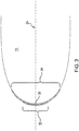
- FIG. 3 is a schematic diagram depicting different zones of ice-accretion associated with different sizes of super-cooled water droplets.
- airfoil 12 depicted in FIG. 2 is shown in magnification to demonstrate a relationship between water droplet size and impingement region.
- Two different impingement regions 32, 34 are depicted proximate leading edge 30 of airfoil 22.
- Impingement region 32 corresponds to a small region about leading edge 30.
- Small impingement region 32 is a region in which water droplets, which are less than or equal to a relatively small size (such as small water droplets 28a depicted in FIG. 2 ), can impinge, for a given set of aircraft and flying conditions.
- Small water droplets 28a can readily follow flow vectors 26a, 26b, 26c and 26d (depicted in FIG. 2 ).
- Flow vectors 26a and 26b show an airflow pattern above airfoil 22, and flow vectors 26c, 26d show an airflow pattern below airfoil 22.
- Flow vectors 26a and 26b diverge from flow vectors 26c and 26d about central axis 24. Only at locations along leading edge 30 that are proximate central axis 24 can small water droplets 28a impinge airfoil 22. The intersection of leading edge 30 and flow-dividing axis 24 can be called the stagnation point.
- Large impingement region 34 includes portions of airfoil 12 which can be impinged only by water droplets that are larger than a predetermined size (such as large water droplets 28b depicted in FIG. 2 ) for a given set of aircraft and flying conditions. Because larger water droplets 28b can cross flow vectors 26a, 26b, 26c and 26d more readily than can small water droplets 28a, such large water droplets 28b impinge airfoil 12 within larger region (e.g., large impingement region 34) about leading edge 30 than the region (e.g., small impingement region 32) impinged by small water droplets 28a. In this way, FIG. 3 demonstrates a relation that exists between a size of water droplets and a regional area in which such sized water droplets are capable of impingement.
- FIG. 4 is a graph of exemplary relations of size of an ice-accretion region versus size of super-cooled water droplets.
- graph 32 has horizontal axis 34 and vertical axis 36.
- Horizontal axis 34 represents maximum size DMAX of water droplets in an atmosphere.
- Vertical axis 36 represents a distance dimension (e.g., angle ⁇ from stagnation point or chord length d from the stagnation point) of impingement region.
- Graph 32 has three relations 38a, 38b and 38c.
- Relation 38a represents a relation between maximum size DMAX of water droplets and distance dimension of impingement region for a first set of icing conditions.
- Relations 38b, 38c represent relations between maximum size DMAX of water droplets and distance dimension of impingement region for a second and a third set of icing conditions, respectively.
- Parameters that affect icing conditions can include aircraft conditions, flying conditions, and atmospheric conditions, for example.
- Aircraft conditions can include, for example, a shape of a structure to which water droplets impinge, temperature of a surface of the impingement region, aircraft configuration, etc.
- Flying conditions can include, for example, an angle of attack, an angle of side-slip, an airspeed, water droplet temperature, liquid water content, etc.
- Atmospheric conditions can include air temperature, air pressure, etc.
- Various embodiments may be more or less affected by one or more of the icing conditions. For example, some embodiments maybe more or less sensitive to angle of attack.
- a structure that presents substantially the same shape to the airflow independent of angle of attack, for example, may be not very sensitive to angle of attack.
- Some geometries may be less sensitive to angle of sideslip, for example.
- FIGS. 5A-5B are perspective and schematic views of an embodiment of an ice-accretion detection system that uses a resonant cavity.
- ice accretion detection system 16 includes sensors 22 and sense circuitry 40.
- sensors 22 is configured to be mounted to an aircraft wing such that sensing surface region 42 is flush with a surrounding adjacent surface of the aircraft wing 12.
- Sense circuitry 40 can be mounted inside of the aircraft wing, or in an electronics bay of the aircraft, for example.
- Sense circuitry 40 can include sensor electrical driver 41 configured to provide an electrical excitation signal to sensors 22.
- Sense circuitry 40 can also include signal detector 43 configured to detect a signal responsive to the provided electrical excitation signal, the detected signal indicative of ice accretion on the sensing surface region of the sensor.
- sensors 22 has resonant cavity 22C that has at least one surface, such as sensing surface region 22, that vibrates in response to a changing electro-magnetic field.
- Each of sensing surface regions 42 of sensors 22 is an exterior surface of resonant cavity 22C.
- the signal detected by signal detector 43 is a resonant frequency of resonant cavity 22C. The resonant frequency changes in response to ice accretion on sensing surface region 42.
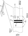
- FIG. 6 is a schematic diagram of an aircraft equipped with an automated ice accretion detection system that measures surface conductivity.
- surface conduction sensor 22' and temperature sensor 44 are mounted to wing 12.
- Surface conduction sensor 22' is configured to measure the surface conductivity of wing 12 at the testing location where surface conduction sensor 22' is mounted.
- Surface conduction sensor 22' includes first and second exposed conductors 46A and 46B on the sensing surface so as to be exposed to an atmosphere adjacent to the sensing surface.
- First and second conductors 46A and 46B are configured to sense current flow therebetween. Ice accretion on the sensing surface and spanning separation distance ⁇ between first and second exposed conductors 46A and 46B facilitates current flow therebetween.
- the measured conduction, or equivalently the measured resistance, between exposed conductors 46A and 46B is indicative of ice accretion on the surface region.
- FIGS. 7A-7B are perspective and schematic views of an embodiment of an ice-accretion detection system that measures a surface conductivity.
- ice accretion detection system 16' includes sensor 22' and sense circuitry 40'.
- Sensor 22' sensor is configured to be mounted to an airfoil of an aircraft such that sensing surface region 42' is flush with or flat upon a surrounding adjacent surface of the airfoil.
- Sense circuitry 40' can be mounted inside of the aircraft wing, or in an electronics bay of the aircraft, for example.
- Sense circuitry 40' can include sensor electrical driver 41' configured to provide an electrical excitation signal, such as a voltage or current, to sensor 22'.
- Sense circuitry 40' can also include signal detector 43' configured to detect a signal responsive to the provided electrical excitation signal, the detected signal indicative of ice accretion on sensing surface region 42' of sensor 22'.
- sensor 22' has first and second conductors 46A and 46B.
- First and second conductors 46A and 46B are configured to sense current flow therebetween.
- First and second conductors 46A and 46B are separated from one another via insulative region 48 therebetween.
- FIG. 8 is a graph depicting a size span of water droplets vs. location along a chord of a convex-shaped housing.
- graph 50 has horizontal axis 52 and vertical axis 54.
- Horizontal axis 52 represents location along a chord of a convex exterior surface exposed to an atmosphere containing super-cooled water droplets.
- Vertical axis 54 represents a size of the super-cooled water droplets.
- Graph 50 includes droplet size/location relation 56 corresponding to a size of super-cooled droplets that can strike the convex exterior surface at the indicated location.
- Line 62 identifies the relation corresponding to the predetermined minimum size of super-cooled water droplets that contribute to ice accretion vs. location along the chord of the convex shaped housing. Droplets smaller than the minimum size will follow the airflow vectors and will not impinge the convex-shaped housing except at locations near the stagnation point.
- Dashed line 64 identifies the maximum size of super-cooled water droplets contained in the cloud atmosphere.
- Point 58 of relation 56 corresponds to the boundary location separating an ice accretion portion and an ice-free portion of the convex exterior surface for the cloud atmosphere having the maximum size of super-cooled water droplet corresponding to dashed line 64. Not all sizes of particles, however, contribute to ice accretion at every location within the ice accretion portion of the convex exterior surface.
- relation 56 indicates that only super-cooled water droplets equal to the maximum size (or greater if the cloud atmosphere had greater sized particles) accrete at the boundary location.
- the region to the right of point 58 on graph 50 corresponds to the ice-free portion of the convex exterior surface, and points to the left of point 58 correspond to the ice-accretion portion of the convex exterior surface.
- Vertical line 60 of relation 56 corresponds to the stagnation point of the convex exterior surface. At the stagnation point corresponding to vertical line 60, super-cooled water droplets of all sizes within the atmosphere contribute to ice accretion. Between point 58 and vertical line 60, super-cooled water droplets that have a size greater than a predetermined minimum will contribute to ice accretion. Super-cooled water droplets smaller than the predetermined minimum size will follow the flow vector lines and not impinge the convex exterior surface and therefore will not contribute to ice accretion.
- Line 62 identifies the relation corresponding to the predetermined minimum size of super-cooled water droplets that contribute to ice accretion vs. location along the chord of the convex shaped housing.
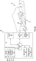
- FIG. 9 is a block diagram of an exemplary ice-accretion-detection/ice-protection system 70.
- ice-accretion-detection/ice-protection system 70 includes controller 72, sensor 22, and ice protection system 14 mounted to airfoil 12 of aircraft 10.
- Controller 72 includes processor(s) 74, ice detection interface 76, ice protection interface 78, aircraft interface 80, storage device(s) 82, user input devices 84, and user output devices 86.
- Storage device(s) 82 has various storage or memory locations.
- Storage device(s) 82 includes program memory 88, conditions data memory 90, boundary calculation module 92, and alert module 94.
- Controller 72 is in communication with ice detection system 16. Ice detection system 16 is configured to monitor ice accretion on sensor surface region 42 (depicted in FIG. 5 ). Sensor surface region 42 is depicted with ice-accretion 20 formed thereon.
- controller 72 includes processor(s) 74, ice detection interface 76, ice protection interface 78, aircraft interface 80, storage device(s) 82, user input devices 84, and user output devices 86.
- controller 72 can include more or fewer components.
- controller 72 may not include user input devices 84 and/or user output devices 86.
- controller 72 may include additional components such as a battery that provides power to components of controller 72 during operation.
- Processor(s) 74 in one example, is configured to implement functionality and/or process instructions for execution within controller 72.
- processor(s) 74 can be capable of processing instructions stored in storage device(s) 82.
- Examples of processor(s) 74 can include any one or more of a microprocessor, a controller, a digital signal processor (DSP), an application specific integrated circuit (ASIC), a field-programmable gate array (FPGA), or other equivalent discrete or integrated logic circuitry.
- DSP digital signal processor
- ASIC application specific integrated circuit
- FPGA field-programmable gate array
- Storage device(s) 82 can be configured to store information within controller 72 during operation.
- Storage device(s) 82 in some examples, is described as computer-readable storage media.
- a computer-readable storage medium can include a non-transitory medium.
- the term "non-transitory" can indicate that the storage medium is not embodied in a carrier wave or a propagated signal.
- a non-transitory storage medium can store data that can, over time, change (e.g., in RAM or cache).
- storage device(s) 82 is a temporary memory, meaning that a primary purpose of storage device(s) 82 is not long-term storage.
- Storage device(s) 82 in some examples, is described as volatile memory, meaning that storage device(s) 82 do not maintain stored contents when power to controller 72 is turned off. Examples of volatile memories can include random access memories (RAM), dynamic random access memories (DRAM), static random access memories (SRAM), and other forms of volatile memories.
- RAM random access memories
- DRAM dynamic random access memories
- SRAM static random access memories
- storage device(s) 82 is used to store program instructions for execution by processor(s) 74.
- Storage device(s) 82 in one example, is used by software or applications running on controller 72 (e.g., ice formation calculation) to temporarily store information during program execution.
- Storage device(s) 82 also include one or more computer-readable storage media.
- Storage device(s) 82 can be configured to store larger amounts of information than volatile memory.
- Storage device(s) 82 can further be configured for long-term storage of information.
- storage device(s) 82 include non-volatile storage elements. Examples of such non-volatile storage elements can include magnetic hard discs, optical discs, flash memories, or forms of electrically programmable memories (EPROM) or electrically erasable and programmable (EEPROM) memories.
- Ice detection interface 76 in some examples, includes a communications module. Ice detection interface 76, in one example, utilizes the communications module to communicate with external devices via one or more networks, such as one or more wireless or wired networks or both.
- the communications module can be a network interface card, such as an Ethernet card, an optical transceiver, a radio frequency transceiver, or any other type of device that can send and receive information.
- Other examples of such network interfaces can include Bluetooth, 3G, 4G, and Wi-Fi 33 radio computing devices as well as Universal Serial Bus (USB).
- Ice protection interface 78 in some examples, includes a communications module. Ice protection interface 78, in one example, utilizes the communications module to communicate with external devices via one or more networks, such as one or more wireless or wired networks or both.
- the communications module can be a network interface card, such as an Ethernet card, an optical transceiver, a radio frequency transceiver, or any other type of device that can send and receive information.
- Other examples of such network interfaces can include Bluetooth, 3G, 4G, and Wi-Fi 33 radio computing devices as well as Universal Serial Bus (USB).
- Aircraft interface 80 can be used to communicate information between controller 72 and an aircraft. In some embodiments, such information can include aircraft conditions, flying conditions, and/or atmospheric conditions. In some embodiments, such information can include data processed by controller 72, such as, for example, alert signals. Aircraft interface 80 can also include a communications module. Aircraft interface 80, in one example, utilizes the communications module to communicate with external devices via one or more networks, such as one or more wireless or wired networks or both.
- the communications module can be a network interface card, such as an Ethernet card, an optical transceiver, a radio frequency transceiver, or any other type of device that can send and receive information.
- network interfaces can include Bluetooth, 3G, 4G, and Wi-Fi 33 radio computing devices as well as Universal Serial Bus (USB).
- communication with the aircraft can be performed via a communications bus, such as, for example, an Aeronautical Radio, Incorporated (ARINC) standard communications protocol.
- ARINC Aeronautical Radio, Incorporated
- aircraft communication with the aircraft can be performed via a communications bus, such as, for example, a Controller Area Network (CAN) bus.
- CAN Controller Area Network
- User input devices 84 are configured to receive input from a user.
- user input devices 84 can include a mouse, a keyboard, a microphone, a camera device, a presence-sensitive and/or touch-sensitive display, push buttons, arrow keys, or other type of device configured to receive input from a user.
- input communication from the user can be performed via a communications bus, such as, for example, an Aeronautical Radio, Incorporated (ARINC) standard communications protocol.
- ARINC Aeronautical Radio, Incorporated
- user input communication from the user can be performed via a communications bus, such as, for example, a Controller Area Network (CAN) bus.
- CAN Controller Area Network
- User output devices 86 can be configured to provide output to a user.
- Examples of user output devices 86 can include a display device, a sound card, a video graphics card, a speaker, a cathode ray tube (CRT) monitor, a liquid crystal display (LCD), a light emitting diode (LED) display, an organic light emitting diode (OLED) display, or other type of device for outputting information in a form understandable to users or machines.
- output communication to the user can be performed via a communications bus, such as, for example, an Aeronautical Radio, Incorporated (ARINC) standard communications protocol.
- ARINC Aeronautical Radio, Incorporated
- output communication to the user can be performed via a communications bus, such as, for example, a Controller Area Network (CAN) bus.
- CAN Controller Area Network
- Apparatus and associated methods relate to a system capable of sensing ice accretion on an airfoil of an aircraft.
- the system includes a sensor having a sensing surface region and configured to be mounted at a mounting location aft of a leading edge of the airfoil such that the sensing surface region is flush with a surrounding adjacent surface of the airfoil. In certain flight conditions, water droplets of sizes less than or equal to a predetermined threshold do not impinge the sensor surface region.
- the system includes a sensor driver coupled to the sensor and configured to provide an excitation signal to the sensor.
- the system also includes a signal detector configured to detect a sensor signal responsive to the provided excitation signal, the detected sensor signal indicative of water particles of sizes exceeding the predetermined threshold impinging the sensing surface region of the sensor.
- a further embodiment of the foregoing system can further include a resonant cavity.
- the sensing surface region of the sensor can be an exterior surface of the resonant cavity.
- the signal detected by the signal detector can be a resonant frequency of the resonant cavity.
- the resonant frequency can change in response to water on the sensing surface region.
- a further embodiment of any of the foregoing systems can further include an alert generator configured to generate an alert signal in response to the detected signal indicative of water particles of a size exceeding the predetermined threshold impinging the sensor surface region of the sensor.
- the senor is a surface resistance sensor having first and second exposed conductors on the sensing surface region so as to be exposed to an atmosphere adjacent to the sensing surface region.
- the surface resistor sensor can include first and second exposed conductors on the sensing surface so as to be exposed to an atmosphere adjacent to the sensing surface.
- first and second conductors can be configured to sense current flow therebetween, wherein ice accretion on the sensing surface and spanning a separation distance between the first and second exposed conductors facilitates current flow therebetween.
- a further embodiment of any of the foregoing systems can further include an icing protection system.
- a further embodiment of any of the foregoing systems can further include a controller configured to control the icing protection system in response to the detected signal indicative of ice accretion.
- the sensor can be a first sensor
- the sensing surface region can be a first sensing surface region
- the mounting location can be a first mounting location
- the surrounding adjacent surface can be a first surrounding adjacent surface
- the predetermined threshold can be a first predetermined threshold
- the excitation signal can be a first excitation signal
- the sensor signal can be a first sensor signal.
- the system can further include a second sensor having a second sensing surface region and configured to be mounted at a second mounting location aft of the first mounting location such that the second sensing surface region is flush with a second surrounding adjacent surface of the airfoil. In certain flight conditions, water particles less than or equal to a second predetermined threshold greater than the first predetermined threshold do not impinge the second sensor surface region at the second mounting location.
- the sensor driver can be coupled to the second sensor and further configured to provide a second excitation signal to the second sensor.
- the signal detector can be further configured to detect a second sensor signal responsive to the provided second excitation signal, the detected sensor signal indicative of water particles of a size exceeding the second predetermined threshold impinging the second sensing surface region of the sensor.
- a further embodiment of any of the foregoing systems can further include a particle size analyzer configured to generate a water particle size histogram based on the first and second sensor signals.
- Some embodiments relate to a method capable of sensing ice accretion on an airfoil of an aircraft.
- the method includes presenting surface region of a sensor aft of a leading edge of the airfoil and flush with a surrounding adjacent surface of the airfoil. In certain flight conditions, water particles of sizes less than or equal to a predetermined threshold do not impinge the sensor surface region.
- the method includes providing, via a sensor driver coupled to the sensor, an excitation signal to the sensor.
- the method includes detecting, via a signal detector, a sensor signal responsive to the provided excitation signal. The detected signal is indicative of water particles of sizes exceeding the predetermined threshold impinging the sensing surface region of the sensor.
- a further embodiment of the foregoing method can further include generating, via an alert generator, an alert signal in response to the detected sensor signal exceeding a predetermined threshold indicative of a predetermined measure of ice accretion.
- a further embodiment of any of the foregoing methods can further include controlling, via a controller, an icing protection system in response to the detected sensor signal indicative of ice accretion.
- detecting a sensor signal responsive to the provided excitation signal can include detecting a resonant frequency of the resonant cavity.
- detecting a sensor signal responsive to the provided excitation signal can include sensing current flow between first and second conductors of a surface resistance sensor.
- Some embodiments relate to a system for sensing ice accretion on an airfoil of an aircraft.
- the system includes a sensor having a sensing surface region, one or more processors, and computer-readable memory.
- the sensor is configured to be mounted at a mounting location aft of a leading edge of the airfoil such that the sensing surface region is flush with a surrounding adjacent surface of the airfoil.
- water particles of sizes less than or equal to a predetermined threshold do not impinge the sensor surface region at the mounting location.
- the computer-readable memory is encoded with instructions that, when executed by the one or more processors, cause the system to provide an excitation signal to the sensor and to detect a sensor signal responsive to the provided electrical excitation signal.
- the detected sensor signal is indicative of water particles of sizes exceeding the predetermined threshold impinging the sensing surface region of the sensor.
- the computer-readable memory can be further encoded with instructions that, when executed by the one or more processors, cause the system to generate an alert signal in response to the detected signal exceeding the predetermined threshold indicative of water particles of sizes exceeding the predetermined threshold impinging the sensor surface region of the sensor.
- a further embodiment of any of the foregoing systems can further include further comprising an icing protection system.
- the computer-readable memory can be further encoded with instructions that, when executed by the one or more processors, cause the system to control the icing protection system in response to the detected sensor signal indicative of water particles of sizes exceeding the predetermined threshold impinging the sensor surface region of the sensor.
- the senor can be a resonant cavity.
- the sensing surface region of the sensor can be an exterior surface of the resonant cavity.
- the signal detected by the signal detector can be a resonant frequency of the resonant cavity.
- the resonant frequency can change in response to ice accretion on the sensing surface region.
Landscapes
- Engineering & Computer Science (AREA)
- Aviation & Aerospace Engineering (AREA)
- Investigating Or Analyzing Materials By The Use Of Electric Means (AREA)
- Geophysics And Detection Of Objects (AREA)
- Testing Or Calibration Of Command Recording Devices (AREA)
Abstract
Description
- Certain atmospheric conditions can lead to ice formation on aircraft surfaces. Ice formation on aircraft surfaces can increase the weight of the aircraft and can increase the drag of the aircraft. Increasing either the weight or the drag of an aircraft can result in a stall speed that is higher than it would otherwise be in an ice-free condition. Ice formation on lifting surfaces can result in a decrease in a wing's lift and/or a decrease in a propeller's thrust. Ice formation can also affect the controllability of an aircraft by affecting the airflow over control surfaces, such as ailerons.
- Various atmospheric conditions can cause more or less ice formation on an aircraft. For example, water droplet density, total moisture content, air temperature, water droplet temperature, droplet size distribution, etc. all factor into risk of ice formation. Some atmospheric conditions can present little or no risk of ice formation on an aircraft.
- Various aircraft flying conditions can affect locations and/or amounts of ice formation on aircraft surfaces. For example, airspeed, angle of attack, angle of side-slip, and presence of deicing equipment all factor into location and/or risk of ice formation. Some aircraft have been equipped with equipment intended to obtain metrics of the atmosphere so as to predict whether the atmosphere presents a risk of ice-formation on exterior surfaces.
- Apparatus and associated methods relate to a system capable of sensing ice accretion on an airfoil of an aircraft. The system includes a sensor having a sensing surface region and configured to be mounted at a mounting location aft of a leading edge of the airfoil such that the sensing surface region is flush with a surrounding adjacent surface of the airfoil. In certain flight conditions, water particles of sizes less than or equal to a predetermined threshold do not impinge the sensor surface region. The system includes a sensor driver coupled to the sensor and configured to provide an excitation signal to the sensor. The system also includes a signal detector configured to detect a sensor signal responsive to the provided excitation signal, the detected sensor signal indicative of water particles of sizes exceeding the predetermined threshold impinging the sensing surface region of the sensor.
- Some embodiments relate to a method capable of sensing ice accretion on an airfoil of an aircraft. The method includes presenting a sensor surface region of a sensor at a mounting location aft of a leading edge of the airfoil and flush with a surrounding adjacent surface of the airfoil. In certain flight conditions, water particles of sizes less than or equal to a predetermined threshold do not impinge the sensor surface region. The method includes providing, via a sensor driver coupled to the sensor, an excitation signal to the sensor. The method includes detecting, via a signal detector, a sensor signal responsive to the provided excitation signal. The detected signal is indicative of water particles of sizes exceeding the predetermined threshold impinging the sensing surface region of the sensor.
- Some embodiments relate to a system capable of sensing ice accretion on an airfoil of an aircraft. The system includes a sensor having a sensing surface region, one or more processors, and computer-readable memory. The sensor is configured to be mounted at a mounting location aft of a leading edge of the airfoil such that the sensing surface region is flush with a surrounding adjacent surface of the airfoil. In certain flight conditions, water particles of sizes less than or equal to a predetermined threshold do not impinge the sensor surface region. The computer-readable memory is encoded with instructions that, when executed by the one or more processors, cause the system to provide an excitation signal to the sensor and to detect a sensor signal responsive to the provided electrical excitation signal. The detected sensor signal is indicative of water particles of sizes exceeding the predetermined threshold impinging the sensing surface region of the sensor.
- A further aspect of the invention, which the Applicant expressly reserves the right to claim, provides a system capable of sensing ice accretion on an airfoil of an aircraft, the system comprising:
- a sensor having a sensing surface region, the sensor configured to be mounted at a
- mounting location aft of a leading edge of the airfoil such that the sensing surface region is flush with a surrounding adjacent surface of the airfoil, wherein, in certain flight conditions, water particles of sizes less than or equal to a predetermined threshold do not impinge the sensor surface region;
- one or more processors; and
- computer-readable memory encoded with instructions that, when executed by the one or more processors, cause the system to:
- provide an excitation signal to the sensor; and
- detect a sensor signal responsive to the provided electrical excitation signal, the detected sensor signal indicative of water particles of sizes exceeding the predetermined threshold impinging the sensing surface region of the sensor.
- Optionally, the computer-readable memory is further encoded with
instructions that, when executed by the one or more processors, cause the system to:
generate an alert signal in response to the detected signal exceeding the predetermined threshold indicative of water particles of sizes exceeding the predetermined threshold impinging the sensor surface region of the sensor. - In various embodiments, the system may further comprise an icing protection system.
- In various embodiments, the computer-readable memory may be further encoded with instructions that, when executed by the one or more processors, cause the system to:
control the icing protection system in response to the detected sensor signal indicative of water particles of sizes exceeding the predetermined threshold impinging the sensor surface region of the sensor. - In various embodiments, the sensor optionally comprises:
- a resonant cavity,
- wherein the sensing surface region of the sensor is an exterior surface of the resonant cavity,
- wherein the signal detected by the signal detector is a resonant frequency of the resonant cavity, the resonant frequency changing in response to water on the sensing surface region.
-
-
FIG. 1 is a schematic view of an aircraft equipped with an exemplary automated ice accretion detection system. -
FIG. 2 is a schematic diagram of ice accreting on a leading edge of a curved member in an airstream. -
FIG. 3 is a schematic diagram depicting different zones of ice-accretion associated with different sizes of super-cooled water droplets. -
FIG. 4 is a graph of exemplary relations of size of an ice-accretion region versus size of super-cooled water droplets. -
FIGS. 5A-5B are perspective and schematic views of an embodiment of an ice-accretion detection system that uses a resonant cavity. -
FIG. 6 is a schematic diagram of an aircraft equipped with an automated ice accretion detection system that measures surface conductivity. -
FIGS. 7A-7B are perspective and schematic views of an embodiment of an ice-accretion detection system that measures a surface conductivity. -
FIG. 8 is a graph depicting a size span of water droplets vs. location along a chord of a convex-shaped housing. -
FIG. 9 is a block diagram of an embodiment of an ice accretion detection system and an ice protection system. - Apparatus and associated methods relate to differentiating ice accretion caused by different supercooled water droplets on an airfoil of an aircraft. A sensor having a sensing surface region is mounted at a mounting location of the airfoil such that the sensing surface region is flush with a surrounding adjacent surface of the airfoil. Water particles of sizes less than or equal to a predetermined threshold do not impinge the sensor surface region at the mounting location when the aircraft is in flight. A sensor driver provides an excitation signal to the sensor. A signal detector detects a sensor signal responsive to the provided excitation signal. The sensor signal is indicative of water particles exceeding the predetermined threshold impinging the sensing surface region. In some embodiments, the sensing surface region is mechanically coupled to a resonant cavity. In other embodiments, the sensor is a surface resistance sensor configured to sense surface resistance.
-
FIG. 1 is a schematic view of an aircraft equipped with an exemplary automated ice accretion detection system. InFIG. 1 ,aircraft 10 haswing 12 that has anice protection system 14 and an iceaccretion detection system 16.Ice protection system 14 is configured to remove ice from a leadingedge 18 ofwing 12. In some embodiments,ice protection system 14 provides heat to leadingedge 18 so as to melt ice accreted thereto. In other embodiments,ice protection system 14deforms leading edge 18 so as to cause ice to loosen from leadingedge 18. Although leadingedge 18 ofwing 12 is depicted as being ice free, due to the ice removal capability ofice protection system 14,ice accretion 20 is shown aft ofice protection system 14. Iceaccretion detection system 16 hassensors 22, which are mounted towing 12 such that each ofsensors 22 has a surface region that is flush with a surrounding adjacent surface ofwing 12, thereby exposing the surface region to the atmosphere adjacent towing 12. Iceaccretion detection system 16 generates a signal indicative of ice accretion on surface regions ofsensors 22. - Various technologies can be used to detect ice accretion on the exposed surface regions of
sensors 22. For example, in some embodiments, a resonant cavity that is defined at least in part by the surface regions can be used to detect ice accretion upon these surface regions. The resonant cavity can have a resonant frequency that is indicative of ice accretion upon the surface region ofsensor 22. In some embodiments two adjacent conductors can be located on the surface regions ofsensors 22 such that the conductors are exposed to the atmosphere adjacent towing 12. When water or ice accretes on the surface region and spans two adjacent conductors, the conductivity therebetween can be indicative of such conditions. A temperature sensor located in proximity to the surface sensor can be used to differentiate between detection of water and ice. - As will be described below, if conditions permit, ice preferentially forms at different locations on
wing 12. Ice tends to form on leadingedge 18 ofwing 12 and is less likely to form as the air moves more and more aft of leadingedge 18. Ice tends to form increasingly aft of leadingedge 18 as the atmosphere contains super-cooled water droplets of increasing size. Locations ofsensors 22 can be selected so as to detect ice accretion at such locations. Various aft locations can be so selected so as to determine if the atmosphere contains super-cooled water droplets of corresponding predetermined sizes. Various embodiments may use various testing regions. In some embodiments, testing regions may be located on the fuselage ofaircraft 10, for example. In some embodiments, testing regions may be located on an airfoil, such aswing 12 or a tail, ofaircraft 10. In some embodiments, testing regions may be located on some appendage ofaircraft 10. - In the depicted embodiment, the testing regions include various spanwise locations along
wing 12 and at various chordwise locations aft of leadingedge 18. These testing regions are monitored bysensors 22 ofice detection system 16. The specific aft locations relative to leadingedge 18 can be used to determine a size composition of super-cooled water droplets in the atmosphere adjacent towing 12. Some such conditions that affect the locations where ice accretes include: aircraft parameters; flying parameters; and atmospheric conditions. A boundary between where ice accretes and where no ice accretes can be calculated based on one or more of these conditions. For example, fluid dynamic computations can be used to calculate the boundary location between ice-free and ice-accretion regions. In some embodiments, a look-up table may be used to determine the indicative aft location, for example. - If
ice detection system 16 detects ice accretion at one or more of the aft locations wheresensors 22 are mounted, an alert system can generate an alert signal, and/or a control system can controlice protection system 14. In various embodiments, various types of alert signals may be generated. For example, in some embodiments an audible alert signal may be generated. In some embodiments, an alert signal may be in the form of an electrical signal sent to a display device. For example, a display monitor may present an optical image of the testing region along with a flashing alert signal. In some embodiments, an alert signal maybe in the form of a signal to another aircraft system. The signal may be provided as either a simple alert or it may be provided with additional information regarding the size of super-cooled water droplets in the atmosphere outside the aircraft. -
FIG. 2 is a schematic diagram of ice accreting on a leading edge of a curved member in an airstream. InFIG. 2 , three-dimensional wing orairfoil 12 is shown in cross section.Airfoil 12 has flow-dividingaxis 24 aligned with a general direction of airflow. Airflow is represented byflow vectors Water droplets Small water droplets 28a generally follow the flow vectors, because the mass of thesmall water droplets 28a is small. A momentum of thesmall water droplets 28a is correspondingly small, because of the small mass. Because the momentum is small for small water droplets, changing the direction, and thus the momentum, of these small water droplets can be achieved by small forces, such as those imparted byflow vectors Small water droplets 28a impingeairfoil 22 only proximate flow-dividingaxis 24 at leadingedge 30. -
Large water droplets 28b, however, have momentums that are larger than those ofsmall water droplets 28a, due to larger masses of thelarge water droplets 26b. Suchlarge water droplets 28b do not followflow vectors small water droplets 28a. Becauselarge water droplets 28b more readily crossflow vectors large water droplets 28b impingeairfoil 22 along a greater section of leadingedge 30 than is impinged bysmall water droplets 28a.Large water droplets 28b impingeairfoil 22 proximate flow-dividingaxis 24 at leadingedge 30 as dosmall water droplets 28a.Large water droplets 28b also impingeairfoil 22 aft of leadingedge 30 for a distance that is related to the droplet size. Airflow does impart a force onlarge water droplets 28b, and thereforelarge water droplets 28b do experience momentum change. Becauselarge water droplets 28b can undergo such momentum change, these large water droplets impingeairfoil 22 only over a limited range about leadingedge 30. - If
water droplets airfoil 12 or another object (e.g., a fuselage, etc.). Pure water can be super-cooled without freezing in the absence of a nucleation site. Such a scenario is not infrequent in cloud atmospheres. The shock of impingement and/or the structural nucleation sites presented by the impinging object can cause such super-cooled water droplets to freeze almost immediately upon such an impingement event. -
FIG. 3 is a schematic diagram depicting different zones of ice-accretion associated with different sizes of super-cooled water droplets. InFIG. 3 ,airfoil 12 depicted inFIG. 2 is shown in magnification to demonstrate a relationship between water droplet size and impingement region. Twodifferent impingement regions leading edge 30 ofairfoil 22.Impingement region 32 corresponds to a small region about leadingedge 30. -
Small impingement region 32 is a region in which water droplets, which are less than or equal to a relatively small size (such assmall water droplets 28a depicted inFIG. 2 ), can impinge, for a given set of aircraft and flying conditions.Small water droplets 28a can readily followflow vectors FIG. 2 ).Flow vectors airfoil 22, and flowvectors airfoil 22.Flow vectors flow vectors central axis 24. Only at locations along leadingedge 30 that are proximatecentral axis 24 cansmall water droplets 28a impingeairfoil 22. The intersection of leadingedge 30 and flow-dividingaxis 24 can be called the stagnation point. -
Large impingement region 34 includes portions ofairfoil 12 which can be impinged only by water droplets that are larger than a predetermined size (such aslarge water droplets 28b depicted inFIG. 2 ) for a given set of aircraft and flying conditions. Becauselarger water droplets 28b can crossflow vectors small water droplets 28a, suchlarge water droplets 28b impingeairfoil 12 within larger region (e.g., large impingement region 34) about leadingedge 30 than the region (e.g., small impingement region 32) impinged bysmall water droplets 28a. In this way,FIG. 3 demonstrates a relation that exists between a size of water droplets and a regional area in which such sized water droplets are capable of impingement. -
FIG. 4 is a graph of exemplary relations of size of an ice-accretion region versus size of super-cooled water droplets. InFIG. 4 ,graph 32 hashorizontal axis 34 andvertical axis 36.Horizontal axis 34 represents maximum size DMAX of water droplets in an atmosphere.Vertical axis 36 represents a distance dimension (e.g., angle θ from stagnation point or chord length d from the stagnation point) of impingement region.Graph 32 has threerelations Relation 38a represents a relation between maximum size DMAX of water droplets and distance dimension of impingement region for a first set of icing conditions.Relations - Parameters that affect icing conditions can include aircraft conditions, flying conditions, and atmospheric conditions, for example. Aircraft conditions can include, for example, a shape of a structure to which water droplets impinge, temperature of a surface of the impingement region, aircraft configuration, etc. Flying conditions can include, for example, an angle of attack, an angle of side-slip, an airspeed, water droplet temperature, liquid water content, etc. Atmospheric conditions can include air temperature, air pressure, etc. Various embodiments may be more or less affected by one or more of the icing conditions. For example, some embodiments maybe more or less sensitive to angle of attack. A structure that presents substantially the same shape to the airflow independent of angle of attack, for example, may be not very sensitive to angle of attack. Some geometries may be less sensitive to angle of sideslip, for example.
-
FIGS. 5A-5B are perspective and schematic views of an embodiment of an ice-accretion detection system that uses a resonant cavity. InFIGS. 5A-5B , iceaccretion detection system 16 includessensors 22 andsense circuitry 40. Each ofsensors 22 is configured to be mounted to an aircraft wing such thatsensing surface region 42 is flush with a surrounding adjacent surface of theaircraft wing 12.Sense circuitry 40 can be mounted inside of the aircraft wing, or in an electronics bay of the aircraft, for example.Sense circuitry 40 can include sensorelectrical driver 41 configured to provide an electrical excitation signal tosensors 22.Sense circuitry 40 can also includesignal detector 43 configured to detect a signal responsive to the provided electrical excitation signal, the detected signal indicative of ice accretion on the sensing surface region of the sensor. In the depicted embodiment,sensors 22 has resonant cavity 22C that has at least one surface, such assensing surface region 22, that vibrates in response to a changing electro-magnetic field. Each of sensingsurface regions 42 ofsensors 22 is an exterior surface of resonant cavity 22C. The signal detected bysignal detector 43 is a resonant frequency of resonant cavity 22C. The resonant frequency changes in response to ice accretion on sensingsurface region 42. -
FIG. 6 is a schematic diagram of an aircraft equipped with an automated ice accretion detection system that measures surface conductivity. InFIG. 6 , surface conduction sensor 22' andtemperature sensor 44 are mounted towing 12. Surface conduction sensor 22' is configured to measure the surface conductivity ofwing 12 at the testing location where surface conduction sensor 22' is mounted. Surface conduction sensor 22' includes first and secondexposed conductors second conductors exposed conductors conductors -
FIGS. 7A-7B are perspective and schematic views of an embodiment of an ice-accretion detection system that measures a surface conductivity. InFIGS. 7A-7B , ice accretion detection system 16' includes sensor 22' and sense circuitry 40'. Sensor 22' sensor is configured to be mounted to an airfoil of an aircraft such that sensing surface region 42' is flush with or flat upon a surrounding adjacent surface of the airfoil. Sense circuitry 40' can be mounted inside of the aircraft wing, or in an electronics bay of the aircraft, for example. Sense circuitry 40' can include sensor electrical driver 41' configured to provide an electrical excitation signal, such as a voltage or current, to sensor 22'. Sense circuitry 40' can also include signal detector 43' configured to detect a signal responsive to the provided electrical excitation signal, the detected signal indicative of ice accretion on sensing surface region 42' of sensor 22'. In the depicted embodiment, sensor 22' has first andsecond conductors second conductors second conductors insulative region 48 therebetween. -
FIG. 8 is a graph depicting a size span of water droplets vs. location along a chord of a convex-shaped housing. InFIG. 8 ,graph 50 hashorizontal axis 52 andvertical axis 54.Horizontal axis 52 represents location along a chord of a convex exterior surface exposed to an atmosphere containing super-cooled water droplets.Vertical axis 54 represents a size of the super-cooled water droplets.Graph 50 includes droplet size/location relation 56 corresponding to a size of super-cooled droplets that can strike the convex exterior surface at the indicated location. For example, at a given location along the convex-shaped housing (e.g., draw a vertical line from any x-axis location), the exterior surface of the convex-shaped housing will be impinged by droplets exceeding some minimum size up until the maximum sized droplet contained in the cloud atmosphere.Line 62 identifies the relation corresponding to the predetermined minimum size of super-cooled water droplets that contribute to ice accretion vs. location along the chord of the convex shaped housing. Droplets smaller than the minimum size will follow the airflow vectors and will not impinge the convex-shaped housing except at locations near the stagnation point. Dashedline 64 identifies the maximum size of super-cooled water droplets contained in the cloud atmosphere. - For a given size of a super-cooled water droplet (e.g., draw a horizontal line from any y-axis location), the exterior surface of the convex-shaped housing will be impinged for the stagnation point up to a maximum impingement location corresponding to the given size of super-cooled water droplet.
Point 58 ofrelation 56 corresponds to the boundary location separating an ice accretion portion and an ice-free portion of the convex exterior surface for the cloud atmosphere having the maximum size of super-cooled water droplet corresponding to dashedline 64. Not all sizes of particles, however, contribute to ice accretion at every location within the ice accretion portion of the convex exterior surface. Atpoint 58,relation 56 indicates that only super-cooled water droplets equal to the maximum size (or greater if the cloud atmosphere had greater sized particles) accrete at the boundary location. The region to the right ofpoint 58 ongraph 50 corresponds to the ice-free portion of the convex exterior surface, and points to the left ofpoint 58 correspond to the ice-accretion portion of the convex exterior surface. -
Vertical line 60 ofrelation 56 corresponds to the stagnation point of the convex exterior surface. At the stagnation point corresponding tovertical line 60, super-cooled water droplets of all sizes within the atmosphere contribute to ice accretion. Betweenpoint 58 andvertical line 60, super-cooled water droplets that have a size greater than a predetermined minimum will contribute to ice accretion. Super-cooled water droplets smaller than the predetermined minimum size will follow the flow vector lines and not impinge the convex exterior surface and therefore will not contribute to ice accretion.Line 62 identifies the relation corresponding to the predetermined minimum size of super-cooled water droplets that contribute to ice accretion vs. location along the chord of the convex shaped housing. -
FIG. 9 is a block diagram of an exemplary ice-accretion-detection/ice-protection system 70. InFIG. 9 , ice-accretion-detection/ice-protection system 70 includescontroller 72,sensor 22, andice protection system 14 mounted toairfoil 12 ofaircraft 10.Controller 72 includes processor(s) 74,ice detection interface 76,ice protection interface 78,aircraft interface 80, storage device(s) 82,user input devices 84, anduser output devices 86. Storage device(s) 82 has various storage or memory locations. Storage device(s) 82 includesprogram memory 88, conditions data memory 90,boundary calculation module 92, andalert module 94.Controller 72 is in communication withice detection system 16.Ice detection system 16 is configured to monitor ice accretion on sensor surface region 42 (depicted inFIG. 5 ).Sensor surface region 42 is depicted with ice-accretion 20 formed thereon. - As illustrated in
FIG. 5 ,controller 72 includes processor(s) 74,ice detection interface 76,ice protection interface 78,aircraft interface 80, storage device(s) 82,user input devices 84, anduser output devices 86. However, in certain examples,controller 72 can include more or fewer components. For instance, in examples wherecontroller 72 is an avionics unit,controller 72 may not includeuser input devices 84 and/oruser output devices 86. In some examples, such as wherecontroller 72 is a mobile or portable device such as a laptop computer,controller 72 may include additional components such as a battery that provides power to components ofcontroller 72 during operation. - Processor(s) 74, in one example, is configured to implement functionality and/or process instructions for execution within
controller 72. For instance, processor(s) 74 can be capable of processing instructions stored in storage device(s) 82. Examples of processor(s) 74 can include any one or more of a microprocessor, a controller, a digital signal processor (DSP), an application specific integrated circuit (ASIC), a field-programmable gate array (FPGA), or other equivalent discrete or integrated logic circuitry. - Storage device(s) 82 can be configured to store information within
controller 72 during operation. Storage device(s) 82, in some examples, is described as computer-readable storage media. In some examples, a computer-readable storage medium can include a non-transitory medium. The term "non-transitory" can indicate that the storage medium is not embodied in a carrier wave or a propagated signal. In certain examples, a non-transitory storage medium can store data that can, over time, change (e.g., in RAM or cache). In some examples, storage device(s) 82 is a temporary memory, meaning that a primary purpose of storage device(s) 82 is not long-term storage. Storage device(s) 82, in some examples, is described as volatile memory, meaning that storage device(s) 82 do not maintain stored contents when power tocontroller 72 is turned off. Examples of volatile memories can include random access memories (RAM), dynamic random access memories (DRAM), static random access memories (SRAM), and other forms of volatile memories. In some examples, storage device(s) 82 is used to store program instructions for execution by processor(s) 74. Storage device(s) 82, in one example, is used by software or applications running on controller 72 (e.g., ice formation calculation) to temporarily store information during program execution. - Storage device(s) 82, in some examples, also include one or more computer-readable storage media. Storage device(s) 82 can be configured to store larger amounts of information than volatile memory. Storage device(s) 82 can further be configured for long-term storage of information. In some examples, storage device(s) 82 include non-volatile storage elements. Examples of such non-volatile storage elements can include magnetic hard discs, optical discs, flash memories, or forms of electrically programmable memories (EPROM) or electrically erasable and programmable (EEPROM) memories.
-
Ice detection interface 76, in some examples, includes a communications module.Ice detection interface 76, in one example, utilizes the communications module to communicate with external devices via one or more networks, such as one or more wireless or wired networks or both. The communications module can be a network interface card, such as an Ethernet card, an optical transceiver, a radio frequency transceiver, or any other type of device that can send and receive information. Other examples of such network interfaces can include Bluetooth, 3G, 4G, and Wi-Fi 33 radio computing devices as well as Universal Serial Bus (USB). -
Ice protection interface 78, in some examples, includes a communications module.Ice protection interface 78, in one example, utilizes the communications module to communicate with external devices via one or more networks, such as one or more wireless or wired networks or both. The communications module can be a network interface card, such as an Ethernet card, an optical transceiver, a radio frequency transceiver, or any other type of device that can send and receive information. Other examples of such network interfaces can include Bluetooth, 3G, 4G, and Wi-Fi 33 radio computing devices as well as Universal Serial Bus (USB). -
Aircraft interface 80 can be used to communicate information betweencontroller 72 and an aircraft. In some embodiments, such information can include aircraft conditions, flying conditions, and/or atmospheric conditions. In some embodiments, such information can include data processed bycontroller 72, such as, for example, alert signals.Aircraft interface 80 can also include a communications module.Aircraft interface 80, in one example, utilizes the communications module to communicate with external devices via one or more networks, such as one or more wireless or wired networks or both. The communications module can be a network interface card, such as an Ethernet card, an optical transceiver, a radio frequency transceiver, or any other type of device that can send and receive information. Other examples of such network interfaces can include Bluetooth, 3G, 4G, and Wi-Fi 33 radio computing devices as well as Universal Serial Bus (USB). In some embodiments, communication with the aircraft can be performed via a communications bus, such as, for example, an Aeronautical Radio, Incorporated (ARINC) standard communications protocol. In an exemplary embodiment, aircraft communication with the aircraft can be performed via a communications bus, such as, for example, a Controller Area Network (CAN) bus. -
User input devices 84, in some examples, are configured to receive input from a user. Examples ofuser input devices 84 can include a mouse, a keyboard, a microphone, a camera device, a presence-sensitive and/or touch-sensitive display, push buttons, arrow keys, or other type of device configured to receive input from a user. In some embodiments, input communication from the user can be performed via a communications bus, such as, for example, an Aeronautical Radio, Incorporated (ARINC) standard communications protocol. In an exemplary embodiment, user input communication from the user can be performed via a communications bus, such as, for example, a Controller Area Network (CAN) bus. -
User output devices 86 can be configured to provide output to a user. Examples ofuser output devices 86 can include a display device, a sound card, a video graphics card, a speaker, a cathode ray tube (CRT) monitor, a liquid crystal display (LCD), a light emitting diode (LED) display, an organic light emitting diode (OLED) display, or other type of device for outputting information in a form understandable to users or machines. In some embodiments, output communication to the user can be performed via a communications bus, such as, for example, an Aeronautical Radio, Incorporated (ARINC) standard communications protocol. In an exemplary embodiment, output communication to the user can be performed via a communications bus, such as, for example, a Controller Area Network (CAN) bus. - The following are non-exclusive descriptions of possible embodiments of the present invention.
- Apparatus and associated methods relate to a system capable of sensing ice accretion on an airfoil of an aircraft. The system includes a sensor having a sensing surface region and configured to be mounted at a mounting location aft of a leading edge of the airfoil such that the sensing surface region is flush with a surrounding adjacent surface of the airfoil. In certain flight conditions, water droplets of sizes less than or equal to a predetermined threshold do not impinge the sensor surface region. The system includes a sensor driver coupled to the sensor and configured to provide an excitation signal to the sensor. The system also includes a signal detector configured to detect a sensor signal responsive to the provided excitation signal, the detected sensor signal indicative of water particles of sizes exceeding the predetermined threshold impinging the sensing surface region of the sensor.
- The system of the preceding paragraph can optionally include, additionally and/or alternatively, any one or more of the following features, configurations and/or additional components:
A further embodiment of the foregoing system can further include a resonant cavity. The sensing surface region of the sensor can be an exterior surface of the resonant cavity. The signal detected by the signal detector can be a resonant frequency of the resonant cavity. The resonant frequency can change in response to water on the sensing surface region. - A further embodiment of any of the foregoing systems can further include an alert generator configured to generate an alert signal in response to the detected signal indicative of water particles of a size exceeding the predetermined threshold impinging the sensor surface region of the sensor.
- A further embodiment of any of the foregoing systems, wherein the sensor is a surface resistance sensor having first and second exposed conductors on the sensing surface region so as to be exposed to an atmosphere adjacent to the sensing surface region.
- A further embodiment of any of the foregoing systems, wherein the surface resistor sensor can include first and second exposed conductors on the sensing surface so as to be exposed to an atmosphere adjacent to the sensing surface.
- A further embodiment of any of the foregoing systems, wherein the first and second conductors can be configured to sense current flow therebetween, wherein ice accretion on the sensing surface and spanning a separation distance between the first and second exposed conductors facilitates current flow therebetween.
- A further embodiment of any of the foregoing systems can further include an icing protection system.
- A further embodiment of any of the foregoing systems, wherein the sensor can be configured to be mounted aft of an icing protection system.
- A further embodiment of any of the foregoing systems can further include a controller configured to control the icing protection system in response to the detected signal indicative of ice accretion.
- A further embodiment of any of the foregoing systems, wherein the sensor can be a first sensor, the sensing surface region can be a first sensing surface region, the mounting location can be a first mounting location, the surrounding adjacent surface can be a first surrounding adjacent surface, the predetermined threshold can be a first predetermined threshold, the excitation signal can be a first excitation signal and the sensor signal can be a first sensor signal. The system can further include a second sensor having a second sensing surface region and configured to be mounted at a second mounting location aft of the first mounting location such that the second sensing surface region is flush with a second surrounding adjacent surface of the airfoil. In certain flight conditions, water particles less than or equal to a second predetermined threshold greater than the first predetermined threshold do not impinge the second sensor surface region at the second mounting location.
- The sensor driver can be coupled to the second sensor and further configured to provide a second excitation signal to the second sensor. The signal detector can be further configured to detect a second sensor signal responsive to the provided second excitation signal, the detected sensor signal indicative of water particles of a size exceeding the second predetermined threshold impinging the second sensing surface region of the sensor.
- A further embodiment of any of the foregoing systems can further include a particle size analyzer configured to generate a water particle size histogram based on the first and second sensor signals.
- Some embodiments relate to a method capable of sensing ice accretion on an airfoil of an aircraft. The method includes presenting surface region of a sensor aft of a leading edge of the airfoil and flush with a surrounding adjacent surface of the airfoil. In certain flight conditions, water particles of sizes less than or equal to a predetermined threshold do not impinge the sensor surface region. The method includes providing, via a sensor driver coupled to the sensor, an excitation signal to the sensor. The method includes detecting, via a signal detector, a sensor signal responsive to the provided excitation signal. The detected signal is indicative of water particles of sizes exceeding the predetermined threshold impinging the sensing surface region of the sensor.
- The method of the preceding paragraph can optionally include, additionally and/or alternatively, any one or more of the following features, configurations and/or additional components:
A further embodiment of the foregoing method can further include generating, via an alert generator, an alert signal in response to the detected sensor signal exceeding a predetermined threshold indicative of a predetermined measure of ice accretion. - A further embodiment of any of the foregoing methods can further include controlling, via a controller, an icing protection system in response to the detected sensor signal indicative of ice accretion.
- A further embodiment of any of the foregoing methods, wherein detecting a sensor signal responsive to the provided excitation signal can include detecting a resonant frequency of the resonant cavity.
- A further embodiment of any of the foregoing methods, wherein detecting a sensor signal responsive to the provided excitation signal can include sensing current flow between first and second conductors of a surface resistance sensor.
- Some embodiments relate to a system for sensing ice accretion on an airfoil of an aircraft. The system includes a sensor having a sensing surface region, one or more processors, and computer-readable memory. The sensor is configured to be mounted at a mounting location aft of a leading edge of the airfoil such that the sensing surface region is flush with a surrounding adjacent surface of the airfoil. In certain flight conditions, water particles of sizes less than or equal to a predetermined threshold do not impinge the sensor surface region at the mounting location. The computer-readable memory is encoded with instructions that, when executed by the one or more processors, cause the system to provide an excitation signal to the sensor and to detect a sensor signal responsive to the provided electrical excitation signal. The detected sensor signal is indicative of water particles of sizes exceeding the predetermined threshold impinging the sensing surface region of the sensor.
- A further embodiment of the foregoing system, wherein the computer-readable memory can be further encoded with instructions that, when executed by the one or more processors, cause the system to generate an alert signal in response to the detected signal exceeding the predetermined threshold indicative of water particles of sizes exceeding the predetermined threshold impinging the sensor surface region of the sensor.
- A further embodiment of any of the foregoing systems can further include further comprising an icing protection system.
- A further embodiment of any of the foregoing systems, wherein the computer-readable memory can be further encoded with instructions that, when executed by the one or more processors, cause the system to control the icing protection system in response to the detected sensor signal indicative of water particles of sizes exceeding the predetermined threshold impinging the sensor surface region of the sensor.
- A further embodiment of any of the foregoing systems, wherein the sensor can be a resonant cavity. The sensing surface region of the sensor can be an exterior surface of the resonant cavity. The signal detected by the signal detector can be a resonant frequency of the resonant cavity. The resonant frequency can change in response to ice accretion on the sensing surface region.
- While the invention has been described with reference to an exemplary embodiment(s), it will be understood by those skilled in the art that various changes may be made and equivalents may be substituted for elements thereof without departing from the scope of the invention. In addition, many modifications may be made to adapt a particular situation or material to the teachings of the invention without departing from the essential scope thereof. Therefore, it is intended that the invention not be limited to the particular embodiment(s) disclosed, but that the invention will include all embodiments falling within the scope of the appended claims.
Claims (15)
- A system capable of sensing ice accretion on an airfoil of an aircraft, the system comprising:a sensor having a sensing surface region, the sensor configured to be mounted at a mounting location aft of a leading edge of the airfoil such that the sensing surface region is flush with a surrounding adjacent surface of the airfoil, wherein, in certain flight conditions, water droplets of sizes less than or equal to a predetermined threshold do not impinge the sensor surface region;a sensor driver coupled to the sensor and configured to provide an excitation signal to the sensor; anda signal detector configured to detect a sensor signal responsive to the provided excitation signal, the detected sensor signal indicative of water particles of sizes exceeding the predetermined threshold impinging the sensing surface region of the sensor.
- The system of claim 1, wherein the sensor comprises:a resonant cavity,wherein the sensing surface region of the sensor is an exterior surface of the resonant cavity,wherein the signal detected by the signal detector is a resonant frequency of the resonant cavity, the resonant frequency changing in response to water on the sensing surface region.
- The system of claim 1 or 2, further comprising:
an alert generator configured to generate an alert signal in response to the detected signal indicative of water particles of a size exceeding the predetermined threshold impinging the sensor surface region of the sensor. - The system of claim 1, 2 or 3, wherein the sensor comprises:
a surface resistance sensor having first and second exposed conductors on the sensing surface region so as to be exposed to an atmosphere adjacent to the sensing surface. - The system of claim 4, wherein the first and second conductors are configured to sense current flow therebetween, wherein ice accretion on the sensing surface and spanning a separation distance between the first and second exposed conductors facilitates current flow therebetween.
- The system of any preceding claim, further comprising an icing protection system.
- The system of claim 6, wherein the sensor is configured to be mounted aft of an icing protection system.
- The system of claim 6 or 7, further comprising:
a controller configured to control the icing protection system in response to the detected signal indicative of ice accretion. - The system of any preceding claim, wherein the sensor is a first sensor, the sensing surface region is a first sensing surface region, the mounting location is a first mounting location, the surrounding adjacent surface is a first surrounding adjacent surface, the predetermined threshold is a first predetermined threshold, the excitation signal is a first excitation signal and the sensor signal is a first sensor signal, the system further comprising:a second sensor having a second sensing surface region, the second sensor configured to be mounted at a second mounting location aft of the first mounting location such that the second sensing surface region is flush with a second surrounding adjacent surface of the airfoil, wherein, in certain flight conditions, water particles less than or equal to a second predetermined threshold greater than the first predetermined threshold do not impinge the second sensor surface region at the second mounting location,wherein the sensor driver is coupled to the second sensor and further configured to provide a second excitation signal to the second sensor,wherein the signal detector is further configured to detect a second sensor signal responsive to the provided second excitation signal, the detected sensor signal indicative of water particles of a size exceeding the second predetermined threshold impinging the second sensing surface region of the sensor.
- The system of claim 9, further comprising:
a particle size analyzer configured to generate a water particle size histogram based on the first and second sensor signals. - A method capable of sensing ice accretion on an airfoil of an aircraft, the method comprising:presenting a sensing surface region of a sensor aft of a leading edge of the airfoil and flush with a surrounding adjacent surface of the airfoil, wherein, in certain flight conditions, water particles of sizes less than or equal to a predetermined threshold do not impinge the sensor surface region;providing, via a sensor driver coupled to the sensor, an excitation signal to the sensor; anddetecting, via a signal detector, a sensor signal responsive to the provided excitation signal, the detected signal indicative of water particles of sizes exceeding the predetermined threshold impinging the sensing surface region of the sensor.
- The method of claim 11, further comprising:
generating, via an alert generator, an alert signal in response to the detected sensor signal exceeding a predetermined threshold indicative of a predetermined measure of ice accretion. - The method of claim 11 or 12, further comprising:
controlling, via a controller, an icing protection system in response to the detected sensor signal indicative of ice accretion. - The method of claim 11, 12 or 13, wherein detecting a sensor signal responsive to the provided excitation signal includes:
detecting a resonant frequency of the resonant cavity. - The method of any of claims 11 to 14, wherein detecting a sensor signal responsive to the provided excitation signal includes:
sensing current flow between first and second conductors of a surface resistance sensor.
Applications Claiming Priority (1)
| Application Number | Priority Date | Filing Date | Title |
|---|---|---|---|
| US15/969,111 US10435161B1 (en) | 2018-05-02 | 2018-05-02 | Surface sensing for droplet size differentiation |
Publications (2)
| Publication Number | Publication Date |
|---|---|
| EP3564129A1 true EP3564129A1 (en) | 2019-11-06 |
| EP3564129B1 EP3564129B1 (en) | 2023-02-15 |
Family
ID=66349457
Family Applications (1)
| Application Number | Title | Priority Date | Filing Date |
|---|---|---|---|
| EP19172127.3A Active EP3564129B1 (en) | 2018-05-02 | 2019-05-01 | Surface sensing for droplet size differentiation |
Country Status (3)
| Country | Link |
|---|---|
| US (1) | US10435161B1 (en) |
| EP (1) | EP3564129B1 (en) |
| CN (1) | CN110435898B (en) |
Families Citing this family (8)
| Publication number | Priority date | Publication date | Assignee | Title |
|---|---|---|---|---|
| US11142334B2 (en) * | 2017-12-19 | 2021-10-12 | Textron Innovations Inc. | Bird impact resistant protection system |
| US11459112B2 (en) * | 2019-07-19 | 2022-10-04 | Rosemount Aerospace Inc. | Active aircraft probe heat monitor and method of use |
| CN111114793B (en) * | 2019-12-13 | 2021-06-01 | 武汉航空仪表有限责任公司 | Icing detection system capable of detecting large supercooled water drops |
| CN114754971B (en) * | 2022-06-15 | 2022-09-02 | 中国空气动力研究与发展中心低速空气动力研究所 | Method and device for testing height of anhydrous shielding area |
| US12416485B2 (en) | 2022-06-17 | 2025-09-16 | Rosemont Aerospace Inc. | Additive material integrated heater deposited or embedded within an ice detector |
| US12174149B2 (en) | 2022-08-18 | 2024-12-24 | Rosemount Aerospace Inc. | Variable shape sensing element of a magnetostrictive oscillating ice detector sensor for improved ice collection efficiency using additive manufacturing |
| CN115292656B (en) * | 2022-09-22 | 2022-12-20 | 北京弘象科技有限公司 | Aircraft ice accretion prediction method and device based on fuzzy logic |
| CN117585166B (en) * | 2023-11-23 | 2026-05-08 | 中国商用飞机有限责任公司 | Supercooled large water droplet detector |
Citations (6)
| Publication number | Priority date | Publication date | Assignee | Title |
|---|---|---|---|---|
| EP0393960A1 (en) * | 1989-04-20 | 1990-10-24 | Simmonds Precision Products Inc. | Ice detecting apparatus and methods |
| WO1994020819A1 (en) * | 1993-03-09 | 1994-09-15 | Innovative Dynamics, Inc. | Method of and apparatus for measuring ice distribution profiles |
| US5474261A (en) * | 1993-09-20 | 1995-12-12 | Raton Technology Research, Inc. | Ice detection apparatus for transportation safety |
| EP0849586A2 (en) * | 1996-12-20 | 1998-06-24 | The B.F. Goodrich Company | Detection of substances on surfaces and electrodes therefor |
| EP1336564A2 (en) * | 2002-02-14 | 2003-08-20 | Lockheed Martin Corporation | Method and apparatus for detecting and measuring thickness of ice on aircraft |
| US20160257414A1 (en) * | 2012-06-12 | 2016-09-08 | The Boeing Company | Icing condition detection method |
Family Cites Families (16)
| Publication number | Priority date | Publication date | Assignee | Title |
|---|---|---|---|---|
| AU8358975A (en) * | 1974-08-05 | 1977-02-03 | Commw Of Australia | Accretion |
| US20040024538A1 (en) * | 2000-08-18 | 2004-02-05 | Rosemount Aerospace Inc. | Liquid water content measurement apparatus and method using rate of change of ice accretion |
| US6759962B2 (en) * | 2001-04-25 | 2004-07-06 | Rosemount Aerospace Inc. | Inflight ice detector to distinguish supercooled large droplet (SLD) icing |
| JP4620002B2 (en) | 2006-07-07 | 2011-01-26 | 川崎重工業株式会社 | Droplet collision sensor device and anti-icing device |
| AU2007309287B2 (en) * | 2006-09-25 | 2010-09-16 | Rosemount Aerospace Inc. | Detecting ice particles |
| US7370525B1 (en) * | 2006-10-31 | 2008-05-13 | Swan International Sensors Pty. Ltd. | Inflight ice detection system |
| CN102336272B (en) * | 2010-07-16 | 2015-01-14 | 中国商用飞机有限责任公司 | Icing detector probe and icing detector comprising same |
| US8517601B2 (en) * | 2010-09-10 | 2013-08-27 | Ultra Electronics Limited | Ice detection system and method |
| US9555894B2 (en) * | 2012-04-27 | 2017-01-31 | Goodrich Corporation | Aircraft ice protection optimization based on ice-detection input |
| CN104296957B (en) | 2014-09-11 | 2017-08-11 | 中国商用飞机有限责任公司 | Method and system for measuring water drop collection coefficient of aerodynamic surface |
| CN205256681U (en) | 2015-08-31 | 2016-05-25 | 中国商用飞机有限责任公司 | Icing condition detection system and aircraft with same |
| US9914543B2 (en) | 2015-12-09 | 2018-03-13 | The Boeing Company | System and method for aircraft ice detection within a zone of non-detection |
| GB2547635A (en) | 2016-02-16 | 2017-08-30 | Penny & Giles Aerospace Ltd | Sensor method |
| US10343783B2 (en) * | 2016-04-28 | 2019-07-09 | Rosemount Aerospace Inc. | Method and apparatus of detecting liquid water in a cloud |
| US10124900B2 (en) | 2016-06-28 | 2018-11-13 | Rosemount Aerospace Inc. | Automated super-cooled water-droplet size differentiation using aircraft accretion patterns |
| US10625869B2 (en) * | 2016-06-28 | 2020-04-21 | Rosemount Aerospace Inc. | Automated super-cooled water-droplet size differentiation using aircraft accretion patterns |
-
2018
- 2018-05-02 US US15/969,111 patent/US10435161B1/en active Active
-
2019
- 2019-04-30 CN CN201910359970.3A patent/CN110435898B/en active Active
- 2019-05-01 EP EP19172127.3A patent/EP3564129B1/en active Active
Patent Citations (6)
| Publication number | Priority date | Publication date | Assignee | Title |
|---|---|---|---|---|
| EP0393960A1 (en) * | 1989-04-20 | 1990-10-24 | Simmonds Precision Products Inc. | Ice detecting apparatus and methods |
| WO1994020819A1 (en) * | 1993-03-09 | 1994-09-15 | Innovative Dynamics, Inc. | Method of and apparatus for measuring ice distribution profiles |
| US5474261A (en) * | 1993-09-20 | 1995-12-12 | Raton Technology Research, Inc. | Ice detection apparatus for transportation safety |
| EP0849586A2 (en) * | 1996-12-20 | 1998-06-24 | The B.F. Goodrich Company | Detection of substances on surfaces and electrodes therefor |
| EP1336564A2 (en) * | 2002-02-14 | 2003-08-20 | Lockheed Martin Corporation | Method and apparatus for detecting and measuring thickness of ice on aircraft |
| US20160257414A1 (en) * | 2012-06-12 | 2016-09-08 | The Boeing Company | Icing condition detection method |
Also Published As
| Publication number | Publication date |
|---|---|
| CN110435898B (en) | 2024-09-20 |
| EP3564129B1 (en) | 2023-02-15 |
| CN110435898A (en) | 2019-11-12 |
| US10435161B1 (en) | 2019-10-08 |
Similar Documents
| Publication | Publication Date | Title |
|---|---|---|
| EP3564129B1 (en) | Surface sensing for droplet size differentiation | |
| EP3263459B1 (en) | Automated super-cooled water-droplet size differentiation using aircraft accretion patterns | |
| EP3398855B1 (en) | Ice accretion boundary locator | |
| EP3264103B1 (en) | Air data sensing probe with icing condition detector | |
| US10124901B2 (en) | Icing condition detection method | |
| EP2990336B1 (en) | Detecting inflight icing conditions on aircraft | |
| EP3480117A1 (en) | Aircraft stall warning/protection with time - varying maximum angle of attack settings for icing conditions | |
| US10093426B2 (en) | Super-cooled water-droplet size indicator | |
| EP3243752B1 (en) | Method and apparatus of detecting liquid water in a cloud with a magnetostrictive resonator | |
| EP3263460B1 (en) | Automated super-cooled water-droplet size differentiation using aircraft accretion patterns | |
| CN104039650A (en) | Supercooled large drop icing condition detection system | |
| US20240367803A1 (en) | Moisture icing detection system and method | |
| EP2801829A1 (en) | Methods and apparatus to determine aircraft flight conditions | |
| EP2701027B1 (en) | Systems and methods for monitoring low speed of a rotorcraft | |
| EP3865880B1 (en) | Determining aircraft flying conditions based on acoustic signals caused by airflow | |
| EP4215442B1 (en) | Ice protection modulation with atmospheric conditions | |
| EP3428066A1 (en) | Redundant heating of surfaces of an aircraft skin for controlling ice accretion | |
| BR102017011192B1 (en) | SUPER-COOLED WATER GROLET SIZE MEASUREMENT SYSTEM AND METHOD TO GENERATE AN ALERT |
Legal Events
| Date | Code | Title | Description |
|---|---|---|---|
| PUAI | Public reference made under article 153(3) epc to a published international application that has entered the european phase |
Free format text: ORIGINAL CODE: 0009012 |
|
| STAA | Information on the status of an ep patent application or granted ep patent |
Free format text: STATUS: THE APPLICATION HAS BEEN PUBLISHED |
|
| AK | Designated contracting states |
Kind code of ref document: A1 Designated state(s): AL AT BE BG CH CY CZ DE DK EE ES FI FR GB GR HR HU IE IS IT LI LT LU LV MC MK MT NL NO PL PT RO RS SE SI SK SM TR |
|
| AX | Request for extension of the european patent |
Extension state: BA ME |
|
| STAA | Information on the status of an ep patent application or granted ep patent |
Free format text: STATUS: REQUEST FOR EXAMINATION WAS MADE |
|
| 17P | Request for examination filed |
Effective date: 20191203 |
|
| RBV | Designated contracting states (corrected) |
Designated state(s): AL AT BE BG CH CY CZ DE DK EE ES FI FR GB GR HR HU IE IS IT LI LT LU LV MC MK MT NL NO PL PT RO RS SE SI SK SM TR |
|
| STAA | Information on the status of an ep patent application or granted ep patent |
Free format text: STATUS: EXAMINATION IS IN PROGRESS |
|
| 17Q | First examination report despatched |
Effective date: 20210208 |
|
| GRAP | Despatch of communication of intention to grant a patent |
Free format text: ORIGINAL CODE: EPIDOSNIGR1 |
|
| STAA | Information on the status of an ep patent application or granted ep patent |
Free format text: STATUS: GRANT OF PATENT IS INTENDED |
|
| INTG | Intention to grant announced |
Effective date: 20220824 |
|
| GRAS | Grant fee paid |
Free format text: ORIGINAL CODE: EPIDOSNIGR3 |
|
| GRAA | (expected) grant |
Free format text: ORIGINAL CODE: 0009210 |
|
| STAA | Information on the status of an ep patent application or granted ep patent |
Free format text: STATUS: THE PATENT HAS BEEN GRANTED |
|
| AK | Designated contracting states |
Kind code of ref document: B1 Designated state(s): AL AT BE BG CH CY CZ DE DK EE ES FI FR GB GR HR HU IE IS IT LI LT LU LV MC MK MT NL NO PL PT RO RS SE SI SK SM TR |
|
| REG | Reference to a national code |
Ref country code: CH Ref legal event code: EP Ref country code: GB Ref legal event code: FG4D |
|
| REG | Reference to a national code |
Ref country code: DE Ref legal event code: R096 Ref document number: 602019025209 Country of ref document: DE |
|
| REG | Reference to a national code |
Ref country code: AT Ref legal event code: REF Ref document number: 1548130 Country of ref document: AT Kind code of ref document: T Effective date: 20230315 Ref country code: IE Ref legal event code: FG4D |
|
| REG | Reference to a national code |
Ref country code: LT Ref legal event code: MG9D |
|
| REG | Reference to a national code |
Ref country code: NL Ref legal event code: MP Effective date: 20230215 |
|
| REG | Reference to a national code |
Ref country code: AT Ref legal event code: MK05 Ref document number: 1548130 Country of ref document: AT Kind code of ref document: T Effective date: 20230215 |
|
| PG25 | Lapsed in a contracting state [announced via postgrant information from national office to epo] |
Ref country code: RS Free format text: LAPSE BECAUSE OF FAILURE TO SUBMIT A TRANSLATION OF THE DESCRIPTION OR TO PAY THE FEE WITHIN THE PRESCRIBED TIME-LIMIT Effective date: 20230215 Ref country code: PT Free format text: LAPSE BECAUSE OF FAILURE TO SUBMIT A TRANSLATION OF THE DESCRIPTION OR TO PAY THE FEE WITHIN THE PRESCRIBED TIME-LIMIT Effective date: 20230615 Ref country code: NO Free format text: LAPSE BECAUSE OF FAILURE TO SUBMIT A TRANSLATION OF THE DESCRIPTION OR TO PAY THE FEE WITHIN THE PRESCRIBED TIME-LIMIT Effective date: 20230515 Ref country code: NL Free format text: LAPSE BECAUSE OF FAILURE TO SUBMIT A TRANSLATION OF THE DESCRIPTION OR TO PAY THE FEE WITHIN THE PRESCRIBED TIME-LIMIT Effective date: 20230215 Ref country code: LV Free format text: LAPSE BECAUSE OF FAILURE TO SUBMIT A TRANSLATION OF THE DESCRIPTION OR TO PAY THE FEE WITHIN THE PRESCRIBED TIME-LIMIT Effective date: 20230215 Ref country code: LT Free format text: LAPSE BECAUSE OF FAILURE TO SUBMIT A TRANSLATION OF THE DESCRIPTION OR TO PAY THE FEE WITHIN THE PRESCRIBED TIME-LIMIT Effective date: 20230215 Ref country code: HR Free format text: LAPSE BECAUSE OF FAILURE TO SUBMIT A TRANSLATION OF THE DESCRIPTION OR TO PAY THE FEE WITHIN THE PRESCRIBED TIME-LIMIT Effective date: 20230215 Ref country code: ES Free format text: LAPSE BECAUSE OF FAILURE TO SUBMIT A TRANSLATION OF THE DESCRIPTION OR TO PAY THE FEE WITHIN THE PRESCRIBED TIME-LIMIT Effective date: 20230215 Ref country code: AT Free format text: LAPSE BECAUSE OF FAILURE TO SUBMIT A TRANSLATION OF THE DESCRIPTION OR TO PAY THE FEE WITHIN THE PRESCRIBED TIME-LIMIT Effective date: 20230215 |
|
| PG25 | Lapsed in a contracting state [announced via postgrant information from national office to epo] |
Ref country code: SE Free format text: LAPSE BECAUSE OF FAILURE TO SUBMIT A TRANSLATION OF THE DESCRIPTION OR TO PAY THE FEE WITHIN THE PRESCRIBED TIME-LIMIT Effective date: 20230215 Ref country code: PL Free format text: LAPSE BECAUSE OF FAILURE TO SUBMIT A TRANSLATION OF THE DESCRIPTION OR TO PAY THE FEE WITHIN THE PRESCRIBED TIME-LIMIT Effective date: 20230215 Ref country code: IS Free format text: LAPSE BECAUSE OF FAILURE TO SUBMIT A TRANSLATION OF THE DESCRIPTION OR TO PAY THE FEE WITHIN THE PRESCRIBED TIME-LIMIT Effective date: 20230615 Ref country code: GR Free format text: LAPSE BECAUSE OF FAILURE TO SUBMIT A TRANSLATION OF THE DESCRIPTION OR TO PAY THE FEE WITHIN THE PRESCRIBED TIME-LIMIT Effective date: 20230516 Ref country code: FI Free format text: LAPSE BECAUSE OF FAILURE TO SUBMIT A TRANSLATION OF THE DESCRIPTION OR TO PAY THE FEE WITHIN THE PRESCRIBED TIME-LIMIT Effective date: 20230215 |
|
| PG25 | Lapsed in a contracting state [announced via postgrant information from national office to epo] |
Ref country code: SM Free format text: LAPSE BECAUSE OF FAILURE TO SUBMIT A TRANSLATION OF THE DESCRIPTION OR TO PAY THE FEE WITHIN THE PRESCRIBED TIME-LIMIT Effective date: 20230215 Ref country code: RO Free format text: LAPSE BECAUSE OF FAILURE TO SUBMIT A TRANSLATION OF THE DESCRIPTION OR TO PAY THE FEE WITHIN THE PRESCRIBED TIME-LIMIT Effective date: 20230215 Ref country code: EE Free format text: LAPSE BECAUSE OF FAILURE TO SUBMIT A TRANSLATION OF THE DESCRIPTION OR TO PAY THE FEE WITHIN THE PRESCRIBED TIME-LIMIT Effective date: 20230215 Ref country code: DK Free format text: LAPSE BECAUSE OF FAILURE TO SUBMIT A TRANSLATION OF THE DESCRIPTION OR TO PAY THE FEE WITHIN THE PRESCRIBED TIME-LIMIT Effective date: 20230215 Ref country code: CZ Free format text: LAPSE BECAUSE OF FAILURE TO SUBMIT A TRANSLATION OF THE DESCRIPTION OR TO PAY THE FEE WITHIN THE PRESCRIBED TIME-LIMIT Effective date: 20230215 |
|
| REG | Reference to a national code |
Ref country code: DE Ref legal event code: R097 Ref document number: 602019025209 Country of ref document: DE |
|
| PG25 | Lapsed in a contracting state [announced via postgrant information from national office to epo] |
Ref country code: SK Free format text: LAPSE BECAUSE OF FAILURE TO SUBMIT A TRANSLATION OF THE DESCRIPTION OR TO PAY THE FEE WITHIN THE PRESCRIBED TIME-LIMIT Effective date: 20230215 |
|
| PLBE | No opposition filed within time limit |
Free format text: ORIGINAL CODE: 0009261 |
|
| STAA | Information on the status of an ep patent application or granted ep patent |
Free format text: STATUS: NO OPPOSITION FILED WITHIN TIME LIMIT |
|
| REG | Reference to a national code |
Ref country code: CH Ref legal event code: PL |
|
| PG25 | Lapsed in a contracting state [announced via postgrant information from national office to epo] |
Ref country code: MC Free format text: LAPSE BECAUSE OF FAILURE TO SUBMIT A TRANSLATION OF THE DESCRIPTION OR TO PAY THE FEE WITHIN THE PRESCRIBED TIME-LIMIT Effective date: 20230215 |
|
| 26N | No opposition filed |
Effective date: 20231116 |
|
| REG | Reference to a national code |
Ref country code: BE Ref legal event code: MM Effective date: 20230531 |
|
| PG25 | Lapsed in a contracting state [announced via postgrant information from national office to epo] |
Ref country code: SI Free format text: LAPSE BECAUSE OF FAILURE TO SUBMIT A TRANSLATION OF THE DESCRIPTION OR TO PAY THE FEE WITHIN THE PRESCRIBED TIME-LIMIT Effective date: 20230215 Ref country code: MC Free format text: LAPSE BECAUSE OF FAILURE TO SUBMIT A TRANSLATION OF THE DESCRIPTION OR TO PAY THE FEE WITHIN THE PRESCRIBED TIME-LIMIT Effective date: 20230215 Ref country code: LU Free format text: LAPSE BECAUSE OF NON-PAYMENT OF DUE FEES Effective date: 20230501 Ref country code: LI Free format text: LAPSE BECAUSE OF NON-PAYMENT OF DUE FEES Effective date: 20230531 Ref country code: CH Free format text: LAPSE BECAUSE OF NON-PAYMENT OF DUE FEES Effective date: 20230531 |
|
| REG | Reference to a national code |
Ref country code: IE Ref legal event code: MM4A |
|
| PG25 | Lapsed in a contracting state [announced via postgrant information from national office to epo] |
Ref country code: IE Free format text: LAPSE BECAUSE OF NON-PAYMENT OF DUE FEES Effective date: 20230501 |
|
| PG25 | Lapsed in a contracting state [announced via postgrant information from national office to epo] |
Ref country code: IE Free format text: LAPSE BECAUSE OF NON-PAYMENT OF DUE FEES Effective date: 20230501 |
|
| PG25 | Lapsed in a contracting state [announced via postgrant information from national office to epo] |
Ref country code: IT Free format text: LAPSE BECAUSE OF FAILURE TO SUBMIT A TRANSLATION OF THE DESCRIPTION OR TO PAY THE FEE WITHIN THE PRESCRIBED TIME-LIMIT Effective date: 20230215 Ref country code: BE Free format text: LAPSE BECAUSE OF NON-PAYMENT OF DUE FEES Effective date: 20230531 |
|
| PG25 | Lapsed in a contracting state [announced via postgrant information from national office to epo] |
Ref country code: BG Free format text: LAPSE BECAUSE OF FAILURE TO SUBMIT A TRANSLATION OF THE DESCRIPTION OR TO PAY THE FEE WITHIN THE PRESCRIBED TIME-LIMIT Effective date: 20230215 |
|
| PG25 | Lapsed in a contracting state [announced via postgrant information from national office to epo] |
Ref country code: BG Free format text: LAPSE BECAUSE OF FAILURE TO SUBMIT A TRANSLATION OF THE DESCRIPTION OR TO PAY THE FEE WITHIN THE PRESCRIBED TIME-LIMIT Effective date: 20230215 |
|
| PGFP | Annual fee paid to national office [announced via postgrant information from national office to epo] |
Ref country code: DE Payment date: 20250423 Year of fee payment: 7 |
|
| PGFP | Annual fee paid to national office [announced via postgrant information from national office to epo] |
Ref country code: GB Payment date: 20250423 Year of fee payment: 7 |
|
| PGFP | Annual fee paid to national office [announced via postgrant information from national office to epo] |
Ref country code: FR Payment date: 20250423 Year of fee payment: 7 |
|
| PG25 | Lapsed in a contracting state [announced via postgrant information from national office to epo] |
Ref country code: CY Free format text: LAPSE BECAUSE OF FAILURE TO SUBMIT A TRANSLATION OF THE DESCRIPTION OR TO PAY THE FEE WITHIN THE PRESCRIBED TIME-LIMIT; INVALID AB INITIO Effective date: 20190501 |
|
| PG25 | Lapsed in a contracting state [announced via postgrant information from national office to epo] |
Ref country code: HU Free format text: LAPSE BECAUSE OF FAILURE TO SUBMIT A TRANSLATION OF THE DESCRIPTION OR TO PAY THE FEE WITHIN THE PRESCRIBED TIME-LIMIT; INVALID AB INITIO Effective date: 20190501 |
|
| PG25 | Lapsed in a contracting state [announced via postgrant information from national office to epo] |
Ref country code: TR Free format text: LAPSE BECAUSE OF FAILURE TO SUBMIT A TRANSLATION OF THE DESCRIPTION OR TO PAY THE FEE WITHIN THE PRESCRIBED TIME-LIMIT Effective date: 20230215 |
|
| P01 | Opt-out of the competence of the unified patent court (upc) registered |
Free format text: CASE NUMBER: UPC_APP_0017929_3564129/2025 Effective date: 20251217 |