EP3564099A1 - Tractor - Google Patents
Tractor Download PDFInfo
- Publication number
- EP3564099A1 EP3564099A1 EP18767635.8A EP18767635A EP3564099A1 EP 3564099 A1 EP3564099 A1 EP 3564099A1 EP 18767635 A EP18767635 A EP 18767635A EP 3564099 A1 EP3564099 A1 EP 3564099A1
- Authority
- EP
- European Patent Office
- Prior art keywords
- release
- engine hood
- engine
- cover member
- unit
- Prior art date
- Legal status (The legal status is an assumption and is not a legal conclusion. Google has not performed a legal analysis and makes no representation as to the accuracy of the status listed.)
- Granted
Links
Images




Classifications
-
- B—PERFORMING OPERATIONS; TRANSPORTING
- B62—LAND VEHICLES FOR TRAVELLING OTHERWISE THAN ON RAILS
- B62D—MOTOR VEHICLES; TRAILERS
- B62D25/00—Superstructure or monocoque structure sub-units; Parts or details thereof not otherwise provided for
- B62D25/08—Front or rear portions
- B62D25/10—Bonnets or lids, e.g. for trucks, tractors, busses, work vehicles
- B62D25/12—Parts or details thereof
-
- B—PERFORMING OPERATIONS; TRANSPORTING
- B62—LAND VEHICLES FOR TRAVELLING OTHERWISE THAN ON RAILS
- B62D—MOTOR VEHICLES; TRAILERS
- B62D49/00—Tractors
-
- B—PERFORMING OPERATIONS; TRANSPORTING
- B62—LAND VEHICLES FOR TRAVELLING OTHERWISE THAN ON RAILS
- B62D—MOTOR VEHICLES; TRAILERS
- B62D25/00—Superstructure or monocoque structure sub-units; Parts or details thereof not otherwise provided for
- B62D25/08—Front or rear portions
- B62D25/10—Bonnets or lids, e.g. for trucks, tractors, busses, work vehicles
-
- E—FIXED CONSTRUCTIONS
- E05—LOCKS; KEYS; WINDOW OR DOOR FITTINGS; SAFES
- E05B—LOCKS; ACCESSORIES THEREFOR; HANDCUFFS
- E05B83/00—Vehicle locks specially adapted for particular types of wing or vehicle
- E05B83/16—Locks for luggage compartments, car boot lids or car bonnets
-
- E—FIXED CONSTRUCTIONS
- E05—LOCKS; KEYS; WINDOW OR DOOR FITTINGS; SAFES
- E05B—LOCKS; ACCESSORIES THEREFOR; HANDCUFFS
- E05B83/00—Vehicle locks specially adapted for particular types of wing or vehicle
- E05B83/16—Locks for luggage compartments, car boot lids or car bonnets
- E05B83/24—Locks for luggage compartments, car boot lids or car bonnets for car bonnets
Definitions
- the present invention mainly relates to a tractor having a structure that deters its engine hood from being easily unlocked.
- Patent Literatures 1 and 2 disclose a tractor of this type.
- the tractor of PTL 1 has an operation unit (release operation unit) below its engine hood. By an operator manually pulling this operation unit, the engine hood is unlocked to be openable.
- the tractor of PTL 2 has a release lever (release operation unit) in the interior of its engine hood.
- the engine hood is unlocked to be openable by an operator inserting a release member from below the engine hood to operate the release lever.
- the lock is released by inserting the release member from the underneath of the engine hood into the interior of the engine hood. This requires the operator to perform the unlocking operation of the engine hood in a straining posture.
- the present invention is made in view of the above circumstances, and it is a primary object of the present invention to provide a tractor having a structure that can deter an unintended person from easily unlocking the engine hood, while allowing the operator to unlock the engine hood in a non-straining posture.
- a tractor having the following structure. Namely, the tractor includes an engine hood, engine frames, a lock unit, a release operation unit, and a cover member.
- an engine In the interior of the engine hood, an engine is arranged.
- a pair of right and left engine frames are provided and arranged in such a manner as to match their longitudinal directions with a front-rear direction to support the engine.
- the lock unit deters the engine hood from being opened.
- the release operation unit is coupled to the lock unit and configured to allow releasing locking of the lock unit through an operation of moving its operable part, the operable part being arranged outward of the engine frames relative to a right-left direction, in a position to be exposed to the exterior.
- the cover member covers the release operation unit so as to disable manual operation of the release operation unit, while allowing operation of the release operation unit at least by using a predetermined release tool, the cover member having an opening portion shaped along a movement locus of the operable part of the release operation unit.
- Covering the release operation unit with the cover member can deter an unintended person from easily unlocking the engine hood. Further, since the release operation unit is arranged on the exterior and outward of the engine frames, an operator can unlock the engine hood in a non-straining posture by using a release tool.
- the tractor is preferably structured so that the cover member is constituted by two sheet metal members arranged with a space therebetween, and the release operation unit is arranged between the two sheet metal members.
- the cover member With use of the sheet metal members, the cover member can be light-weighted and produced at low costs.
- the tractor is preferably such that the two sheet metal members respectively have elongated holes constituting the opening portion, in positions corresponding to each other.
- the release tool can penetrate through both of the elongated holes in the two sheet metal members, which facilitates the operator to apply a force. Therefore, the lock of the engine hood can be more easily released by using the release tool.
- the tractor is preferably structured as follows.
- the release operation is an operation of moving the operable part of the release operation unit in a release direction.
- the release operation unit is constituted by a rod-like member, and the operable part is formed by bending at least a side of the rod-like member toward the release direction in a closed manner.
- the tractor is preferably structured as follows. That is, the tractor includes an attachment plate to which the cover member is detachably mounted using a fixing member. A space above the attachment plate is covered by the engine hood.
- the fixing member is removable through an operation on a surface of the attachment plate on the interior side of the engine hood, and is not removable through an operation only on a surface of the attachment plate on the exterior side.
- the lock of the engine hood can be manually released. Therefore, work for opening the engine hood during maintenance becomes easy. Further, since the cover member cannot be removed from the surface on the exterior side, the engine hood cannot be easily unlocked, in a situation such as leaving the tractor outside.
- FIG. 1 is a side view showing a structure of a tractor 1 related to one embodiment of the present invention.
- FIG. 2 is a front perspective view showing a structure in the interior of an engine hood 7.
- the wordings "left”, “right”, and the like mean the left and the right relative to a direction in which the tractor 1 advances, respectively.
- the tractor 1 shown in FIG. 1 is capable of being equipped with various work machines such as a plow, a harrow, and a loader to enable various types of work.
- Front wheels 4 are disposed in a front portion of the tractor 1, and rear wheels 5 are arranged in a rear portion of the tractor 1.
- the engine hood 7 is arranged. In the interior of the engine hood 7, an engine room is structured. The engine hood 7 is deterred from being opened by a lock unit 60 arranged in the interior. Below a front portion of the engine hood 7, an unlock unit 40 is arranged. By operating the unlock unit 40, locking of the lock unit 60 is released (detailed later). By releasing locking of the lock unit 60, the engine hood 7 can be opened and closed by rotating the engine hood 7 about its upper rear end portion as the rotation fulcrum (see dashed-line in FIG. 1 ). By opening the engine hood 7, an operator can access the engine room and perform maintenance and the like.
- a cabin 6 that allows an operator to board is arranged behind the engine hood 7, a cabin 6 that allows an operator to board is arranged.
- the cabin 6 has therein an operation unit 25 for performing various operations and a seat 26.
- the operator of the tractor 1 can perform a traveling operation and the like of the tractor 1 with the operation unit 25.
- a machine body of the tractor 1 is structured by a pair of engine frames 2 arranged on the right and left sides, respectively, and a transmission case 21 fixed in a rear portion of the engine frames 2.
- the engine frames 2 are provided and arranged in such a manner as to match their longitudinal directions with a front-rear direction. Further, front portions of the pair of right and left engine frames 2 are joined together.
- the engine frames 2 support an engine 3 directly or through a vibration isolation member and the like.
- the engine 3 is a common rail type diesel engine having a plurality of cylinders.
- the engine frames 2 have a pair of right and left attachment plate support parts 2a each having a plate-like shape and arranged to face upward (to have its thickness direction match with an up-down direction).
- attachment plate support parts 2a not-shown attachment holes are formed.
- an attachment plate 10 is attached by using the attachment holes and fixing members such as bolts and nuts. This way, the engine frames 2 (attachment plate support parts 2a) support the attachment plate 10. Further, the attachment plate 10 is attached ahead of a part where the engine 3 is supported.
- a fan shroud 12, a radiator 13, a battery 14, an engine controller 15, an air cleaner 16, and a lock unit 60 are arranged directly or through another member.
- a front axle case 22 is attached to bottoms of the engine frames 2. To the front axle case 22, front wheels 4 are attached through a front axle shaft 4a. Rear wheels 5 are attached to the transmission case 21 through a rear wheel shaft 5a. The upper sides of the right and left rear wheels 5 are covered by right and left rear fenders 23, respectively.
- the transmission case 21 decelerates a driving force from the engine 3 and transmits the force to the front axle case 22 and the rear axle shaft 5a. Operation of a shift lever of a not-shown gear-shift operation device by the operator can change the transmission gear ratio in the transmission case 21 thus adjusting the traveling speed of the tractor 1.
- the drive force of the engine 3 is partially transmitted to a PTO shaft (not shown) protruding from the rear end of the transmission case 21.
- a PTO shaft (not shown) protruding from the rear end of the transmission case 21.
- the PTO shaft can drive the work machine through a not-shown universal joint and the like.
- the thus-configured tractor 1 can perform various types of work such as tillage, seeding, and harvesting, while traveling on a field.
- FIG. 3 is a perspective view showing the structures of the unlock unit 40 and the lock unit 60.
- FIG. 4 is a perspective view showing structures of the engine hood 7 and an engine hood frame 7a.
- FIG. 5 is a front view showing the structures of the unlock unit 40 and the lock unit 60.
- the engine hood frame 7a is arranged in the interior, and in the front portion, of the engine hood 7.
- the engine hood frame 7a is a member extending in the up-down direction, and has its upper part connected to a fixing part 7c.
- the engine hood frame 7a is fixed to an interior wall on the front side of the engine hood 7, by using a not-shown attachment hole formed in the fixing part 7c and a fixing member such as a bolt. Therefore, the engine hood frame 7a integrally rotates with the engine hood 7.
- a lock bar 7b is arranged below the engine hood frame 7a.
- the lock unit 60 deters the engine hood 7 from being opened by holding the lock bar 7b. Further, the lock unit 60 is arranged in front of the fan shroud 12 to the engine controller 15, and below the air cleaner 16.
- the lock unit 60 has a base plate 61, a first lock plate 62, a second lock plate 63, a stopper 64, a rotation pin 65, and a biasing spring 66.
- the base plate 61 is attached on an upper surface of the attachment plate 10 (on the interior side of the engine hood 7) by using a fixing member such as a bolt and a nut.
- the first lock plate 62 is attached to the base plate 61 by using a fixing member such as a bolt and a nut.
- the first lock plate 62 has a cut-out portion 62a which is open upward. While the lock unit 60 deters the engine hood 7 from being opened, the lock bar 7b is engaged in the cut-out portion 62a.
- the second lock plate 63 is rotatably attached to the first lock plate 62 by the rotation pin 65.
- the second lock plate 63 has a closing part 63a which closes an upper portion of the cut-out portion 62a. Further, the first lock plate 62 and the second lock plate 63 are each biased by the biasing spring 66 in a direction such that the upper portion of the cut-out portion 62a is closed by the closing part 63a.
- the cut-out portion 62a and the closing part 63a hold the lock bar 7b while no external force is applied, and therefore the engine hood 7 is deterred from being opened.
- the second lock plate 63 has an attachment hole, and an operation wire 41 (an engagement part 41a to be more specific) is engaged with this attachment hole. Pulling the operation wire 41 causes the closing part 63a to rotate in a direction away from the cut-out portion 62a (see a dashed-line of FIG. 5 ). This releases the lock bar 7b, and therefore the locking of the lock unit 60 is released.
- the second lock plate 63 contacts the stopper 64, when rotated by a predetermined amount. Therefore, excessive rotation of the second lock plate 63 can be avoided.
- the unlock unit 40 has the operation wire (release operation unit) 41 and a cover member 42.
- the operation wire 41 is a rod-like member and connects the unlock unit 40 to the lock unit 60.
- the operation wire 41 is arranged so as to penetrate through an insertion hole 10a which is a through hole formed in the attachment plate 10.
- a part of the operation wire 41 is arranged in the interior of the engine hood 7, and the remaining part of the operation wire 41 is arranged in the exterior of the engine hood 7. Further, the longitudinal direction of the operation wire 41 and an operation direction of the operation wire 41 extend obliquely toward lower right.
- One end portion of the operation wire 41 (an end portion on the interior side of the engine hood 7) is bent to form a hook-like engagement part 41a.
- the engagement part 41a is engaged with the second lock plate 63, as hereinabove described.
- the other end portion of the operation wire 41 (an end portion on the side of the exterior of the engine hood 7) is bent to form an annular operable part 41b.
- the operable part 41b is a part to be operated for releasing locking of the lock unit 60. In the present embodiment, locking of the lock unit 60 is released by moving the operable part 41b to one side (outward) of the operation wire 41 relative to its longitudinal direction. This operation is hereinafter referred to as release operation.
- release direction the direction in which the operable part 41b is moved at the time of release operation.
- the release operation is assumed to be performed by using a release tool 100, instead of using a hand.
- this release tool 100 has an elongated cylindrical part for operating the operation wire 41 and a hole part to which a keychain and the like is attached.
- the operable part 41b is arranged outward of the engine frames 2 (specifically, to the further right of the right engine frame 2) and exposed to the exterior. Since this allows the operator to easily confirm the position of the operable part 41b, the operator can easily release locking of the lock unit 60 by using the release tool 100. Further, since there is no need of inserting the release tool 100 into the interior of the engine hood 7, the operator can release locking of the lock unit 60 in a non-straining posture.
- the present embodiment deals with a structure that deters the engine hood 7 from being easily opened by an unintended person, while reducing troubles involved in losing the release tool 100.
- a dedicated release tool cylinder key and the like
- the engine hood 7 cannot be opened, if the dedicated release tool is lost or left in a different place.
- the present embodiment allows unlocking of the engine hood 7 by using a member that can be inserted into the opening portion 42a and that has a certain degree of strength (e.g., a screw driver and the like), instead of using a dedicated release tool. With this, the engine hood 7 can be opened even if the release tool 100 is lost or left at a different place.
- the operable part 41b since the operable part 41b has an annular shape, its end toward the release direction is closed. This facilitates application of a force in the release direction. Application of a force in the release direction is sufficiently facilitated as long as the end toward the release direction is closed. Since the operation wire 41 is biased in the direction opposite to the release direction by the rotation pin 65, there is no need of an operation to move the operable part 41b in the direction opposite to the release direction, when locking the engine hood 7 (closing the engine hood 7 automatically locks the same). Therefore, the operable part 41b may have a U-shape (specifically, a U-shape with its lower right end, which is on the side toward the release direction, closed) similarly to the engagement part 41a.
- a U-shape specifically, a U-shape with its lower right end, which is on the side toward the release direction, closed
- the cover member 42 is attached to a lower surface of the attachment plate 10 (exterior side of the engine hood 7). That is, the cover member 42 is arranged downward of the attachment plate 10 (i.e., on the exterior side of the engine hood 7).
- the cover member 42 is structured to cover the operable part 41b.
- the cover member 42 has the opening portion 42a which is a through hole.
- the opening portion 42a is a portion where the release tool 100 is inserted to perform release operation.
- the opening portion 42a is shaped along the movement locus of the operable part 41b at the time of release operation. Specifically, the opening portion 42a is an elongated hole, and the longitudinal direction thereof substantially matches with the release direction.
- the cover member 42 therefore also serves as a guide for moving the operation wire 41 in an appropriate direction.
- the cover member 42 is a member that deters the operation wire 41 from being easily operated by an unintended person. Specifically, it is a member that deters the engine hood 7 from being easily opened by an unintended person. To this end, the cover member 42 is structured so that the operation wire 41 cannot be operated by a hand, and that the operation wire 41 can be operated by using the release tool 100. Specifically, the diameter of the cylindrical part of the release tool 100 is smaller than the size of a typical finger. A space of the opening portion 42a of the cover member 42 is such that a finger cannot be inserted. Further, a gap 42b is formed at a lower end portion of the cover member 42 relative to the release direction. The size of this gap 42b is also such that a finger cannot be inserted.
- the cover member 42 is arranged so that the operation wire 41 (particularly, the engagement part 41a) does not protrude from the cover member 42.
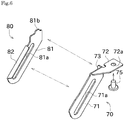
- FIG. 6 is an exploded perspective view of the cover member 42.
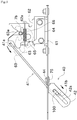
- FIG. 7 is a perspective view showing placing of the cover member 42 over the operation wire 41.
- FIG. 8 is a perspective view showing attaching of the cover member 42 to the attachment plate 10.
- the cover member 42 is structured by joining a first sheet metal member 70 and a second sheet metal member 80 by welding.
- the first sheet metal member 70 has a main part 71, an attaching part 72, and a connection part 73.
- the main part 71 is an elongated part formed along the longitudinal direction of the operation wire 41.
- an elongated hole 71a is formed in the main part 71.
- the elongated hole 71a is a part of the opening portion 42a, and the elongated hole 71a along with an elongated hole 81a (described later) constitute the opening portion 42a.
- the attaching part 72 is a part formed by bending so as to substantially parallel to the attachment plate 10.
- an attachment hole 72a for attachment to the attachment plate 10 is formed.
- a bolt 75 is connected by welding.
- connection part 73 is a part substantially perpendicular to the main part 71, and is a part to be joined with the second sheet metal member 80, as shown in FIG. 6 .
- the second sheet metal member 80 has a main part 81 and a connection part 82.
- the main part 81 is an elongated part formed along the longitudinal direction of the operation wire 41.
- the elongated hole 81a and a protruding part 81b are formed.
- the elongated hole 71a and the elongated hole 81a constitute the opening portion 42a which is a through hole.
- the protruding part 81b is a part that protrudes from the main part 81 toward the attachment plate 10.
- the protruding part 81b is inserted into the insertion hole 10a for the operation wire 41 received therethrough.
- the connection part 82 is a part substantially perpendicular to the main part 81, and is a part to be joined with the first sheet metal member 70, as shown in FIG. 6 .
- the cover member 42 having a substantially box-shape is formed.
- the main part 71 and the main part 81 are welded to each other so as to be substantially parallel to each other, and to have positions of the elongated hole 71a and the elongated hole 81a corresponding to each other.
- the cover member 42 is attached to the attachment plate 10. Specifically, as shown in FIG. 7 , the cover member 42 is set so that the operation wire 41 is positioned in the internal space of the cover member 42. Then, as shown in FIG. 8 , the attachment hole 10b formed in the attachment plate 10 and the bolt 75 protruding upward from the attachment hole 72a of the first sheet metal member 70 are matched with each other. After this, the bolt 75 protruding upward from the attachment hole 10b is fastened by a nut 44. This way, the cover member 42 is attached to the attachment plate 10.
- the cover member 42 is attached by using the bolt 75 and the nut 44.
- the cover member 42 can be removed by removing the nut 44.
- the cover member 42 is removed at a time of inspection or repairing before shipping of the tractor 1. This way, there is no need of using the release tool 100 every time the engine hood 7 is opened (the lock can be released by a hand).
- the bolt 75 is a low head bolt, but may be a bolt of a different type. Further, the bolt 75 does not have to be welded to the attachment plate 10.
- the engine hood 7 is arranged on the front side, above, and the right and left sides of the nut 44. Below the nut 44, the attachment plate 10 is arranged. Behind the nut 44, the fan shroud 12 to battery 14 are arranged as shown in FIG. 2 . As should be understood from this, the nut 44 cannot be accessed unless the engine hood 7 is opened.
- the tractor 1 of the present embodiment includes an engine hood 7, engine frames 2, a lock unit 60, an operation wire 41, and a cover member 42.
- an engine 3 is arranged in the interior of the engine hood 7, an engine 3 is arranged.
- a pair of right and left engine frames 2 are provided and arranged in such a manner as to match their longitudinal directions with the front-rear direction to support the engine 3.
- the lock unit 60 deters the engine hood 7 from being opened.
- the operation wire 41 is coupled to the lock unit 60, and is configured to allow releasing locking of the lock unit 60 through a release operation of moving its operable part 41b.
- the operable part 41b is arranged outward of the engine frames 2 relative to the right-left direction and exposed to the exterior.
- the cover member 42 covers the operation wire 41 so as to disable manual operation of the operation wire 41, while allowing operation of the operation wire 41 at least by using a predetermined release tool 100, the cover member 42 having an opening portion 42a shaped along a movement locus of the operable part 41b of the operation wire 41.
- Covering the operation wire 41 with the cover member 42 can deter an unintended person from easily unlocking the engine hood 7. Further, since the operation wire 41 is arranged on the exterior and outward of the engine frames 2, an operator can unlock the engine hood 7 in a non-straining posture by using a release tool 100.
- the tractor 1 of the present embodiment is structured so that the cover member 42 is constituted by a first sheet metal member 70 and a second sheet metal member 80 arranged with a space therebetween, and the operation wire 41 is arranged between the first sheet metal member 70 and the second sheet metal member 80.
- the cover member 42 can be light-weighted and produced at low costs.
- the tractor 1 of the present embodiment is such that the first sheet metal member 70 and the second sheet metal member 80 respectively have elongated holes 71a and 81a constituting the opening portion 42a, in positions corresponding to each other.
- the release tool 100 can penetrate through both of the elongated holes 71a and 81a in the first sheet metal member 70 and the second sheet metal member 80, which facilitates the operator to apply a force. Therefore, the lock of the engine hood 7 can be more easily released by using the release tool 100.
- the release operation is an operation of moving the operable part 41b of the operation wire 41b in the release direction.
- the operation wire 41 is constituted by a rod-like member, and the operable part 41b is formed by bending at least a side of the rod-like member toward the release direction in a closed manner.
- the tractor 1 of the present embodiment includes an attachment plate 10 to which the cover member 42 is detachably mounted using a nut 44.
- a space above the attachment plate 10 is covered by the engine hood 7.
- the nut 44 is removable through an operation on a surface of the attachment plate 10 on the interior side of the engine hood 7, and is not removable through an operation only on a surface of the attachment plate 10 on the exterior side.
- the lock of the engine hood 7 can be manually released. Therefore, work for opening the engine hood 7 during maintenance becomes easy. Further, since the cover member 42 cannot be removed from the surface on the exterior side, the engine hood 7 cannot be easily unlocked, in a situation such as leaving the tractor 1 outside.
- the unlock unit 40 is attached to the surface of the attachment plate 10 on the side opposite to the lock unit 60 is mounted.
- the unlock unit 40 may be attached to another member (a member different from the one where the lock unit 60 is attached), provided that the unlock unit 40 is connected by the operation wire 41 and the like.
- the unlock unit 40 is detachably structured.
- the unlock unit 40 may be joined to the attachment plate 10 by welding and the like so as to be undetachable.
- the release operation is such that the operable part 41b is moved (pulled) in a direction away from the lock unit 60 (engine hood 7).
- the release operation may be such that the operable part 41b is moved (pushed) towards the lock unit 60.
- the release operation is not limited to an operation that involves a movement in one direction.
- the release operation may involve a movement in a first direction, followed by a movement in a second direction which is different from the first direction.
- the opening portion of the cover member also includes a portion shaped along the first direction and a portion shaped along the second direction.
- the lock unit 60 is arranged nearby a front end portion of the engine hood 7; however, may be arranged in a different position (e.g., nearby an upper end portion of the engine hood 7).
- the tractor 1 of the above embodiment is of a type having the cabin 6 covering the operation unit 25 and the seat 26.
- the present invention is also applicable to a tractor whose operation unit and seat are not covered by the cabin (exposed to the exterior).
Landscapes
- Engineering & Computer Science (AREA)
- Chemical & Material Sciences (AREA)
- Combustion & Propulsion (AREA)
- Transportation (AREA)
- Mechanical Engineering (AREA)
- Superstructure Of Vehicle (AREA)
- Lock And Its Accessories (AREA)
Abstract
Description
- The present invention mainly relates to a tractor having a structure that deters its engine hood from being easily unlocked.
- Traditionally, a tractor is provided with a lock unit that deters an engine hood from opening, and a release operation unit configured to release locking of the lock unit.
Patent Literatures 1 and 2 (PLT 1, PTL 2) disclose a tractor of this type. - The tractor of
PTL 1 has an operation unit (release operation unit) below its engine hood. By an operator manually pulling this operation unit, the engine hood is unlocked to be openable. - The tractor of
PTL 2 has a release lever (release operation unit) in the interior of its engine hood. The engine hood is unlocked to be openable by an operator inserting a release member from below the engine hood to operate the release lever. -
- PTL 1: Japanese Patent Application Laid-Open No.
2011-255695 - PTL 2: Japanese Patent No.
5536696 - Since the engine hood of the tractor of
PTL 1 can be unlocked simply by manual operation, an unintended person can easily open the engine hood. Meanwhile, in the tractor ofPTL 2, the lock is released by inserting the release member from the underneath of the engine hood into the interior of the engine hood. This requires the operator to perform the unlocking operation of the engine hood in a straining posture. - The present invention is made in view of the above circumstances, and it is a primary object of the present invention to provide a tractor having a structure that can deter an unintended person from easily unlocking the engine hood, while allowing the operator to unlock the engine hood in a non-straining posture.
- Problems to be solved by the invention are as described above, and next, means for solving the problems and effects thereof will be described.
- In an aspect of the present invention, a tractor having the following structure is provided. Namely, the tractor includes an engine hood, engine frames, a lock unit, a release operation unit, and a cover member. In the interior of the engine hood, an engine is arranged. A pair of right and left engine frames are provided and arranged in such a manner as to match their longitudinal directions with a front-rear direction to support the engine. The lock unit deters the engine hood from being opened. The release operation unit is coupled to the lock unit and configured to allow releasing locking of the lock unit through an operation of moving its operable part, the operable part being arranged outward of the engine frames relative to a right-left direction, in a position to be exposed to the exterior. The cover member covers the release operation unit so as to disable manual operation of the release operation unit, while allowing operation of the release operation unit at least by using a predetermined release tool, the cover member having an opening portion shaped along a movement locus of the operable part of the release operation unit.
- Covering the release operation unit with the cover member can deter an unintended person from easily unlocking the engine hood. Further, since the release operation unit is arranged on the exterior and outward of the engine frames, an operator can unlock the engine hood in a non-straining posture by using a release tool.
- The tractor is preferably structured so that the cover member is constituted by two sheet metal members arranged with a space therebetween, and the release operation unit is arranged between the two sheet metal members.
- With use of the sheet metal members, the cover member can be light-weighted and produced at low costs.
- The tractor is preferably such that the two sheet metal members respectively have elongated holes constituting the opening portion, in positions corresponding to each other.
- With this, the release tool can penetrate through both of the elongated holes in the two sheet metal members, which facilitates the operator to apply a force. Therefore, the lock of the engine hood can be more easily released by using the release tool.
- The tractor is preferably structured as follows. Namely, the release operation is an operation of moving the operable part of the release operation unit in a release direction. The release operation unit is constituted by a rod-like member, and the operable part is formed by bending at least a side of the rod-like member toward the release direction in a closed manner.
- Since the operation of releasing locking of the lock unit is simple, various tools can be used as the release tool provided that the tool can be inserted into the opening portion. Therefore, user-friendliness can be improved.
- The tractor is preferably structured as follows. That is, the tractor includes an attachment plate to which the cover member is detachably mounted using a fixing member. A space above the attachment plate is covered by the engine hood. The fixing member is removable through an operation on a surface of the attachment plate on the interior side of the engine hood, and is not removable through an operation only on a surface of the attachment plate on the exterior side.
- By removing the cover member, the lock of the engine hood can be manually released. Therefore, work for opening the engine hood during maintenance becomes easy. Further, since the cover member cannot be removed from the surface on the exterior side, the engine hood cannot be easily unlocked, in a situation such as leaving the tractor outside.
-
- [
FIG. 1 ] A side view showing a structure of a tractor related to one embodiment of the present invention. - [
FIG. 2 ] A front perspective view showing a structure in the interior of an engine hood. - [
FIG. 3 ] A perspective view showing structures of an unlock unit and a lock unit. - [
FIG. 4 ] A perspective view showing structures of the engine hood and an engine hood frame. - [
FIG. 5 ] A front view showing the structures of the unlock unit and the lock unit. - [
FIG. 6 ] An exploded perspective view of a cover member. - [
FIG. 7 ] A perspective view showing placing of the cover member over an operation wire. - [
FIG. 8 ] A perspective view showing attaching of the cover member to an attachment plate. - An embodiment of the present invention will be described with reference to the drawings.
FIG. 1 is a side view showing a structure of atractor 1 related to one embodiment of the present invention.FIG. 2 is a front perspective view showing a structure in the interior of anengine hood 7. In the following description, the wordings "left", "right", and the like mean the left and the right relative to a direction in which thetractor 1 advances, respectively. - The
tractor 1 shown inFIG. 1 is capable of being equipped with various work machines such as a plow, a harrow, and a loader to enable various types of work.Front wheels 4 are disposed in a front portion of thetractor 1, and rear wheels 5 are arranged in a rear portion of thetractor 1. - In a front portion of the
tractor 1, theengine hood 7 is arranged. In the interior of theengine hood 7, an engine room is structured. Theengine hood 7 is deterred from being opened by alock unit 60 arranged in the interior. Below a front portion of theengine hood 7, anunlock unit 40 is arranged. By operating theunlock unit 40, locking of thelock unit 60 is released (detailed later). By releasing locking of thelock unit 60, theengine hood 7 can be opened and closed by rotating theengine hood 7 about its upper rear end portion as the rotation fulcrum (see dashed-line inFIG. 1 ). By opening theengine hood 7, an operator can access the engine room and perform maintenance and the like. - As shown in
FIG. 1 , behind theengine hood 7, acabin 6 that allows an operator to board is arranged. Thecabin 6 has therein anoperation unit 25 for performing various operations and aseat 26. The operator of thetractor 1 can perform a traveling operation and the like of thetractor 1 with theoperation unit 25. - As shown in
FIG. 2 , a machine body of thetractor 1 is structured by a pair of engine frames 2 arranged on the right and left sides, respectively, and atransmission case 21 fixed in a rear portion of the engine frames 2. The engine frames 2 are provided and arranged in such a manner as to match their longitudinal directions with a front-rear direction. Further, front portions of the pair of right and left engine frames 2 are joined together. The engine frames 2 support anengine 3 directly or through a vibration isolation member and the like. Theengine 3 is a common rail type diesel engine having a plurality of cylinders. - The engine frames 2 have a pair of right and left attachment
plate support parts 2a each having a plate-like shape and arranged to face upward (to have its thickness direction match with an up-down direction). In the attachmentplate support parts 2a, not-shown attachment holes are formed. On top surfaces of these attachmentplate support parts 2a, anattachment plate 10 is attached by using the attachment holes and fixing members such as bolts and nuts. This way, the engine frames 2 (attachmentplate support parts 2a) support theattachment plate 10. Further, theattachment plate 10 is attached ahead of a part where theengine 3 is supported. On theattachment plate 10, afan shroud 12, aradiator 13, abattery 14, anengine controller 15, anair cleaner 16, and alock unit 60 are arranged directly or through another member. - A
front axle case 22 is attached to bottoms of the engine frames 2. To thefront axle case 22,front wheels 4 are attached through afront axle shaft 4a. Rear wheels 5 are attached to thetransmission case 21 through arear wheel shaft 5a. The upper sides of the right and left rear wheels 5 are covered by right and leftrear fenders 23, respectively. - The
transmission case 21 decelerates a driving force from theengine 3 and transmits the force to thefront axle case 22 and therear axle shaft 5a. Operation of a shift lever of a not-shown gear-shift operation device by the operator can change the transmission gear ratio in thetransmission case 21 thus adjusting the traveling speed of thetractor 1. - The drive force of the
engine 3 is partially transmitted to a PTO shaft (not shown) protruding from the rear end of thetransmission case 21. In thetractor 1, the rear end is structured so that the above-mentioned work machine can be attached. The PTO shaft can drive the work machine through a not-shown universal joint and the like. - The thus-configured
tractor 1 can perform various types of work such as tillage, seeding, and harvesting, while traveling on a field. - Next, the following describes structures of the
unlock unit 40 and thelock unit 60, with reference toFIG. 2 to FIG. 5 .FIG. 3 is a perspective view showing the structures of theunlock unit 40 and thelock unit 60.FIG. 4 is a perspective view showing structures of theengine hood 7 and anengine hood frame 7a.FIG. 5 is a front view showing the structures of theunlock unit 40 and thelock unit 60. - As shown in
FIG. 1 andFIG. 3 , theengine hood frame 7a is arranged in the interior, and in the front portion, of theengine hood 7. Theengine hood frame 7a is a member extending in the up-down direction, and has its upper part connected to a fixingpart 7c. Theengine hood frame 7a is fixed to an interior wall on the front side of theengine hood 7, by using a not-shown attachment hole formed in the fixingpart 7c and a fixing member such as a bolt. Therefore, theengine hood frame 7a integrally rotates with theengine hood 7. Below theengine hood frame 7a, alock bar 7b is arranged. Thelock unit 60 deters theengine hood 7 from being opened by holding thelock bar 7b. Further, thelock unit 60 is arranged in front of thefan shroud 12 to theengine controller 15, and below theair cleaner 16. - First, the structure of the
lock unit 60 is described. As shown inFIG. 3 andFIG. 5 , thelock unit 60 has abase plate 61, afirst lock plate 62, asecond lock plate 63, astopper 64, arotation pin 65, and a biasingspring 66. - The
base plate 61 is attached on an upper surface of the attachment plate 10 (on the interior side of the engine hood 7) by using a fixing member such as a bolt and a nut. Thefirst lock plate 62 is attached to thebase plate 61 by using a fixing member such as a bolt and a nut. Thefirst lock plate 62 has a cut-outportion 62a which is open upward. While thelock unit 60 deters theengine hood 7 from being opened, thelock bar 7b is engaged in the cut-outportion 62a. Thesecond lock plate 63 is rotatably attached to thefirst lock plate 62 by therotation pin 65. Thesecond lock plate 63 has aclosing part 63a which closes an upper portion of the cut-outportion 62a. Further, thefirst lock plate 62 and thesecond lock plate 63 are each biased by the biasingspring 66 in a direction such that the upper portion of the cut-outportion 62a is closed by theclosing part 63a. - With this structure, the cut-out
portion 62a and theclosing part 63a hold thelock bar 7b while no external force is applied, and therefore theengine hood 7 is deterred from being opened. Further, thesecond lock plate 63 has an attachment hole, and an operation wire 41 (anengagement part 41a to be more specific) is engaged with this attachment hole. Pulling theoperation wire 41 causes theclosing part 63a to rotate in a direction away from the cut-outportion 62a (see a dashed-line ofFIG. 5 ). This releases thelock bar 7b, and therefore the locking of thelock unit 60 is released. It should be noted that, thesecond lock plate 63 contacts thestopper 64, when rotated by a predetermined amount. Therefore, excessive rotation of thesecond lock plate 63 can be avoided. - While locking of the
lock unit 60 is released, the operator can manually lift theengine hood 7. In the interior of theengine hood 7, there are a plurality of gas dampers which connect a member that rotates along with rotation of theengine hood 7 and a member that does not rotate even when theengine hood 7 rotates. With this, the operator can smoothly open or close theengine hood 7, while locking of thelock unit 60 is released. - Next, the structure of the
unlock unit 40 is described. As shown inFIG. 3 andFIG. 5 , theunlock unit 40 has the operation wire (release operation unit) 41 and acover member 42. - The
operation wire 41 is a rod-like member and connects theunlock unit 40 to thelock unit 60. Theoperation wire 41 is arranged so as to penetrate through aninsertion hole 10a which is a through hole formed in theattachment plate 10. In other words, a part of theoperation wire 41 is arranged in the interior of theengine hood 7, and the remaining part of theoperation wire 41 is arranged in the exterior of theengine hood 7. Further, the longitudinal direction of theoperation wire 41 and an operation direction of theoperation wire 41 extend obliquely toward lower right. - One end portion of the operation wire 41 (an end portion on the interior side of the engine hood 7) is bent to form a hook-
like engagement part 41a. Theengagement part 41a is engaged with thesecond lock plate 63, as hereinabove described. The other end portion of the operation wire 41 (an end portion on the side of the exterior of the engine hood 7) is bent to form an annularoperable part 41b. Theoperable part 41b is a part to be operated for releasing locking of thelock unit 60. In the present embodiment, locking of thelock unit 60 is released by moving theoperable part 41b to one side (outward) of theoperation wire 41 relative to its longitudinal direction. This operation is hereinafter referred to as release operation. Note that the longitudinal direction of theoperation wire 41 and a direction in which theoperable part 41b is moved do not necessarily have to be strictly the same. Further, in the following description, the direction in which theoperable part 41b is moved at the time of release operation is referred to as release direction. - The release operation is assumed to be performed by using a
release tool 100, instead of using a hand. As shown inFIG. 4 , thisrelease tool 100 has an elongated cylindrical part for operating theoperation wire 41 and a hole part to which a keychain and the like is attached. By the operator inserting the cylindrical part of therelease tool 100 into theoperable part 41b and moving the same in the release direction, locking of thelock unit 60 is released. Theoperable part 41b is arranged outward of the engine frames 2 (specifically, to the further right of the right engine frame 2) and exposed to the exterior. Since this allows the operator to easily confirm the position of theoperable part 41b, the operator can easily release locking of thelock unit 60 by using therelease tool 100. Further, since there is no need of inserting therelease tool 100 into the interior of theengine hood 7, the operator can release locking of thelock unit 60 in a non-straining posture. - The present embodiment deals with a structure that deters the
engine hood 7 from being easily opened by an unintended person, while reducing troubles involved in losing therelease tool 100. To more reliably deter theengine hood 7 from being opened by an unintended person, it is preferable to adopt a dedicated release tool (cylinder key and the like). With this structure however, theengine hood 7 cannot be opened, if the dedicated release tool is lost or left in a different place. In this regard, the present embodiment allows unlocking of theengine hood 7 by using a member that can be inserted into theopening portion 42a and that has a certain degree of strength (e.g., a screw driver and the like), instead of using a dedicated release tool. With this, theengine hood 7 can be opened even if therelease tool 100 is lost or left at a different place. - Further, since the
operable part 41b has an annular shape, its end toward the release direction is closed. This facilitates application of a force in the release direction. Application of a force in the release direction is sufficiently facilitated as long as the end toward the release direction is closed. Since theoperation wire 41 is biased in the direction opposite to the release direction by therotation pin 65, there is no need of an operation to move theoperable part 41b in the direction opposite to the release direction, when locking the engine hood 7 (closing theengine hood 7 automatically locks the same). Therefore, theoperable part 41b may have a U-shape (specifically, a U-shape with its lower right end, which is on the side toward the release direction, closed) similarly to theengagement part 41a. - The
cover member 42 is attached to a lower surface of the attachment plate 10 (exterior side of the engine hood 7). That is, thecover member 42 is arranged downward of the attachment plate 10 (i.e., on the exterior side of the engine hood 7). Thecover member 42 is structured to cover theoperable part 41b. Thecover member 42 has theopening portion 42a which is a through hole. Theopening portion 42a is a portion where therelease tool 100 is inserted to perform release operation. Theopening portion 42a is shaped along the movement locus of theoperable part 41b at the time of release operation. Specifically, theopening portion 42a is an elongated hole, and the longitudinal direction thereof substantially matches with the release direction. Thecover member 42 therefore also serves as a guide for moving theoperation wire 41 in an appropriate direction. - The
cover member 42 is a member that deters theoperation wire 41 from being easily operated by an unintended person. Specifically, it is a member that deters theengine hood 7 from being easily opened by an unintended person. To this end, thecover member 42 is structured so that theoperation wire 41 cannot be operated by a hand, and that theoperation wire 41 can be operated by using therelease tool 100. Specifically, the diameter of the cylindrical part of therelease tool 100 is smaller than the size of a typical finger. A space of theopening portion 42a of thecover member 42 is such that a finger cannot be inserted. Further, agap 42b is formed at a lower end portion of thecover member 42 relative to the release direction. The size of thisgap 42b is also such that a finger cannot be inserted. That is, all the gaps formed in the cover member 42 (gaps that allow access to theoperable part 41b) are smaller than the size of a typical finger. Further, thecover member 42 is arranged so that the operation wire 41 (particularly, theengagement part 41a) does not protrude from thecover member 42. - Next, the following describes a method of manufacturing the
cover member 42, the detailed structure thereof, and a method of attaching thecover member 42.FIG. 6 is an exploded perspective view of thecover member 42.FIG. 7 is a perspective view showing placing of thecover member 42 over theoperation wire 41.FIG. 8 is a perspective view showing attaching of thecover member 42 to theattachment plate 10. - As shown in
FIG. 6 , thecover member 42 is structured by joining a firstsheet metal member 70 and a secondsheet metal member 80 by welding. - The first
sheet metal member 70 has amain part 71, an attachingpart 72, and aconnection part 73. Themain part 71 is an elongated part formed along the longitudinal direction of theoperation wire 41. In themain part 71, anelongated hole 71a is formed. Theelongated hole 71a is a part of theopening portion 42a, and theelongated hole 71a along with anelongated hole 81a (described later) constitute theopening portion 42a. The attachingpart 72 is a part formed by bending so as to substantially parallel to theattachment plate 10. In the attachingpart 72, anattachment hole 72a for attachment to theattachment plate 10 is formed. To the lower surface of the attachingpart 72, abolt 75 is connected by welding. Specifically, as shown inFIG. 7 , thebolt 75 is inserted into theattachment hole 72a from the lower surface of the attachment plate 10 (the exterior surface of the engine hood 7) so that the head portion is downward, and the head portion is welded to the lower surface of theattachment plate 10. Theconnection part 73 is a part substantially perpendicular to themain part 71, and is a part to be joined with the secondsheet metal member 80, as shown inFIG. 6 . - The second
sheet metal member 80 has amain part 81 and aconnection part 82. Themain part 81 is an elongated part formed along the longitudinal direction of theoperation wire 41. In themain part 81, theelongated hole 81a and aprotruding part 81b are formed. As hereinabove described, theelongated hole 71a and theelongated hole 81a constitute theopening portion 42a which is a through hole. The protrudingpart 81b is a part that protrudes from themain part 81 toward theattachment plate 10. The protrudingpart 81b is inserted into theinsertion hole 10a for theoperation wire 41 received therethrough. Theconnection part 82 is a part substantially perpendicular to themain part 81, and is a part to be joined with the firstsheet metal member 70, as shown inFIG. 6 . - As described, by welding the
connection part 73 of the firstsheet metal member 70 to themain part 81, and welding theconnection part 82 of the secondsheet metal member 80 to the firstsheet metal member 70, thecover member 42 having a substantially box-shape is formed. This way, themain part 71 and themain part 81 are welded to each other so as to be substantially parallel to each other, and to have positions of theelongated hole 71a and theelongated hole 81a corresponding to each other. - Next, the
cover member 42 is attached to theattachment plate 10. Specifically, as shown inFIG. 7 , thecover member 42 is set so that theoperation wire 41 is positioned in the internal space of thecover member 42. Then, as shown inFIG. 8 , theattachment hole 10b formed in theattachment plate 10 and thebolt 75 protruding upward from theattachment hole 72a of the firstsheet metal member 70 are matched with each other. After this, thebolt 75 protruding upward from theattachment hole 10b is fastened by anut 44. This way, thecover member 42 is attached to theattachment plate 10. - As should be understood, the
cover member 42 is attached by using thebolt 75 and thenut 44. Thecover member 42 can be removed by removing thenut 44. For example, at a time of inspection or repairing before shipping of thetractor 1, thecover member 42 is removed. This way, there is no need of using therelease tool 100 every time theengine hood 7 is opened (the lock can be released by a hand). - Further, since the
nut 44 is arranged in the interior of theengine hood 7 and thebolt 75 is connected by welding, thenut 44 cannot be removed unless locking of thelock unit 60 is released and theengine hood 7 is opened. That is, while making thecover member 42 detachable to improve the operability at the time of inspection and the like, the security is restrained from being deteriorated because an unintended person cannot remove thecover member 42. Thebolt 75 is a low head bolt, but may be a bolt of a different type. Further, thebolt 75 does not have to be welded to theattachment plate 10. - Regarding the members arranged around the nut 44: the
engine hood 7 is arranged on the front side, above, and the right and left sides of thenut 44. Below thenut 44, theattachment plate 10 is arranged. Behind thenut 44, thefan shroud 12 tobattery 14 are arranged as shown inFIG. 2 . As should be understood from this, thenut 44 cannot be accessed unless theengine hood 7 is opened. - As hereinabove described, the
tractor 1 of the present embodiment includes anengine hood 7, engine frames 2, alock unit 60, anoperation wire 41, and acover member 42. In the interior of theengine hood 7, anengine 3 is arranged. A pair of right and left engine frames 2 are provided and arranged in such a manner as to match their longitudinal directions with the front-rear direction to support theengine 3. Thelock unit 60 deters theengine hood 7 from being opened. Theoperation wire 41 is coupled to thelock unit 60, and is configured to allow releasing locking of thelock unit 60 through a release operation of moving itsoperable part 41b. Theoperable part 41b is arranged outward of the engine frames 2 relative to the right-left direction and exposed to the exterior. Thecover member 42 covers theoperation wire 41 so as to disable manual operation of theoperation wire 41, while allowing operation of theoperation wire 41 at least by using apredetermined release tool 100, thecover member 42 having an openingportion 42a shaped along a movement locus of theoperable part 41b of theoperation wire 41. - Covering the
operation wire 41 with thecover member 42 can deter an unintended person from easily unlocking theengine hood 7. Further, since theoperation wire 41 is arranged on the exterior and outward of the engine frames 2, an operator can unlock theengine hood 7 in a non-straining posture by using arelease tool 100. - The
tractor 1 of the present embodiment is structured so that thecover member 42 is constituted by a firstsheet metal member 70 and a secondsheet metal member 80 arranged with a space therebetween, and theoperation wire 41 is arranged between the firstsheet metal member 70 and the secondsheet metal member 80. - With use of the sheet metal members, the
cover member 42 can be light-weighted and produced at low costs. - The
tractor 1 of the present embodiment is such that the firstsheet metal member 70 and the secondsheet metal member 80 respectively have elongatedholes opening portion 42a, in positions corresponding to each other. - With this, the
release tool 100 can penetrate through both of theelongated holes sheet metal member 70 and the secondsheet metal member 80, which facilitates the operator to apply a force. Therefore, the lock of theengine hood 7 can be more easily released by using therelease tool 100. - In the
tractor 1 of the present embodiment, the release operation is an operation of moving theoperable part 41b of theoperation wire 41b in the release direction. Theoperation wire 41 is constituted by a rod-like member, and theoperable part 41b is formed by bending at least a side of the rod-like member toward the release direction in a closed manner. - Since the operation of releasing locking of the
lock unit 60 is simple, various tools can be used as the release tool provided that the tool can be inserted into theopening portion 42a. Therefore, user-friendliness can be improved. - Further, the
tractor 1 of the present embodiment includes anattachment plate 10 to which thecover member 42 is detachably mounted using anut 44. A space above theattachment plate 10 is covered by theengine hood 7. Thenut 44 is removable through an operation on a surface of theattachment plate 10 on the interior side of theengine hood 7, and is not removable through an operation only on a surface of theattachment plate 10 on the exterior side. - By removing the
cover member 42, the lock of theengine hood 7 can be manually released. Therefore, work for opening theengine hood 7 during maintenance becomes easy. Further, since thecover member 42 cannot be removed from the surface on the exterior side, theengine hood 7 cannot be easily unlocked, in a situation such as leaving thetractor 1 outside. - Although a preferred embodiment of the present invention has been described above, the above-described configuration can be modified, for example, as follows.
- In the above embodiment, the
unlock unit 40 is attached to the surface of theattachment plate 10 on the side opposite to thelock unit 60 is mounted. However, theunlock unit 40 may be attached to another member (a member different from the one where thelock unit 60 is attached), provided that theunlock unit 40 is connected by theoperation wire 41 and the like. - In the above embodiment, the
unlock unit 40 is detachably structured. However, theunlock unit 40 may be joined to theattachment plate 10 by welding and the like so as to be undetachable. - In the above embodiment, the release operation is such that the
operable part 41b is moved (pulled) in a direction away from the lock unit 60 (engine hood 7). However, the release operation may be such that theoperable part 41b is moved (pushed) towards thelock unit 60. Further, the release operation is not limited to an operation that involves a movement in one direction. For example, the release operation may involve a movement in a first direction, followed by a movement in a second direction which is different from the first direction. In this case, the opening portion of the cover member also includes a portion shaped along the first direction and a portion shaped along the second direction. - In the above embodiment, the
lock unit 60 is arranged nearby a front end portion of theengine hood 7; however, may be arranged in a different position (e.g., nearby an upper end portion of the engine hood 7). - The
tractor 1 of the above embodiment is of a type having thecabin 6 covering theoperation unit 25 and theseat 26. However, the present invention is also applicable to a tractor whose operation unit and seat are not covered by the cabin (exposed to the exterior). -
- 1
- tractor
- 2
- engine frame
- 3
- engine
- 5
- rear wheel
- 40
- unlock unit
- 41
- operation wire (release operation unit)
- 42
- cover member
- 75
- bolt
- 44
- nut (fixing member)
- 60
- lock unit
Claims (5)
- A tractor comprising:an engine hood having therein an engine:a pair of right and left engine frames arranged in such a manner as to match their longitudinal directions with a front-rear direction to support the engine;a lock unit configured to deter the engine hood from being opened;a release operation unit coupled to the lock unit and configured to allow releasing locking of the lock unit through an operation of moving its operable part, the operable part being arranged outward of the engine frames relative to a right-left direction, in a position to be exposed to the exterior; anda cover member covering the release operation unit so as to disable manual operation of the release operation unit, while allowing operation of the release operation unit at least by using a predetermined release tool, the cover member having an opening portion shaped along a movement locus of the operable part of the release operation unit.
- The tractor according to claim 1, wherein
the cover member is constituted by two sheet metal members arranged with a space therebetween, and the release operation unit is arranged between the two sheet metal members. - The tractor according to claim 2, wherein
the two sheet metal members respectively have elongated holes constituting the opening portion, in positions corresponding to each other. - The tractor according to claim 1, wherein:a release operation for releasing locking of the lock unit is an operation of moving the operable part of the release operation unit in a release direction; andthe release operation unit is constituted by a rod-like member, and the operable part is formed by bending at least a side of the rod-like member toward the release direction in a closed manner.
- The tractor according to claim 1, comprising
an attachment plate to which the cover member is detachably mounted using a fixing member, wherein:a space above the attachment plate is covered by the engine hood; andthe fixing member is removable through an operation on a surface of the attachment plate on the interior side of the engine hood, and is not removable through an operation only on a surface of the attachment plate on the exterior side.
Applications Claiming Priority (2)
| Application Number | Priority Date | Filing Date | Title |
|---|---|---|---|
| JP2017048218A JP6657134B2 (en) | 2017-03-14 | 2017-03-14 | Tractor |
| PCT/JP2018/007065 WO2018168422A1 (en) | 2017-03-14 | 2018-02-26 | Tractor |
Publications (3)
| Publication Number | Publication Date |
|---|---|
| EP3564099A1 true EP3564099A1 (en) | 2019-11-06 |
| EP3564099A4 EP3564099A4 (en) | 2020-08-19 |
| EP3564099B1 EP3564099B1 (en) | 2024-04-24 |
Family
ID=63523103
Family Applications (1)
| Application Number | Title | Priority Date | Filing Date |
|---|---|---|---|
| EP18767635.8A Active EP3564099B1 (en) | 2017-03-14 | 2018-02-26 | Tractor |
Country Status (5)
| Country | Link |
|---|---|
| US (1) | US11173962B2 (en) |
| EP (1) | EP3564099B1 (en) |
| JP (1) | JP6657134B2 (en) |
| BR (1) | BR112019013912B1 (en) |
| WO (1) | WO2018168422A1 (en) |
Families Citing this family (2)
| Publication number | Priority date | Publication date | Assignee | Title |
|---|---|---|---|---|
| JP6800126B2 (en) * | 2017-10-10 | 2020-12-16 | 株式会社クボタ | Work vehicle |
| USD976968S1 (en) * | 2019-03-22 | 2023-01-31 | Deere & Company | Work vehicle hood |
Family Cites Families (16)
| Publication number | Priority date | Publication date | Assignee | Title |
|---|---|---|---|---|
| JPS5536696B2 (en) | 1972-08-02 | 1980-09-22 | ||
| JPS57150167U (en) * | 1981-03-17 | 1982-09-21 | ||
| JPH0826140A (en) * | 1994-07-13 | 1996-01-30 | Kubota Corp | Bonnet locking device for tractors |
| JPH09132169A (en) * | 1995-11-08 | 1997-05-20 | Toyota Autom Loom Works Ltd | Engine hood opening operation lever of industrial vehicle |
| US7422250B2 (en) * | 2004-10-15 | 2008-09-09 | Autoguard Devices, Llc | Vehicle hood latch protector |
| JP4613082B2 (en) * | 2005-03-14 | 2011-01-12 | ヤンマー株式会社 | Bonnet structure of work vehicle |
| KR100748657B1 (en) * | 2005-10-31 | 2007-08-10 | 현대자동차주식회사 | Locking device of the car trunk |
| ITTO20091046A1 (en) * | 2009-12-28 | 2011-06-29 | Cnh Italia Spa | LOCK WITH A REMOTE ACTUATOR FOR A VEHICLE PANEL |
| US8801052B2 (en) * | 2010-01-11 | 2014-08-12 | Deere & Company | Hood latch |
| JP5427115B2 (en) * | 2010-06-04 | 2014-02-26 | 株式会社クボタ | Bonnet lock device for work vehicle |
| JP5536696B2 (en) | 2011-03-07 | 2014-07-02 | 株式会社Ihiシバウラ | Tractor bonnet |
| JP2013136359A (en) * | 2011-12-28 | 2013-07-11 | Kubota Corp | Tractor |
| JP6120689B2 (en) * | 2013-06-14 | 2017-04-26 | ヤンマー株式会社 | Tractor |
| JP6716095B2 (en) * | 2016-05-30 | 2020-07-01 | 井関農機株式会社 | Work vehicle |
| JP6555245B2 (en) * | 2016-12-20 | 2019-08-07 | 井関農機株式会社 | Tractor |
| JP6657130B2 (en) * | 2017-02-15 | 2020-03-04 | ヤンマー株式会社 | Tractor |
-
2017
- 2017-03-14 JP JP2017048218A patent/JP6657134B2/en active Active
-
2018
- 2018-02-26 BR BR112019013912-5A patent/BR112019013912B1/en active IP Right Grant
- 2018-02-26 WO PCT/JP2018/007065 patent/WO2018168422A1/en not_active Ceased
- 2018-02-26 US US16/493,226 patent/US11173962B2/en not_active Expired - Fee Related
- 2018-02-26 EP EP18767635.8A patent/EP3564099B1/en active Active
Also Published As
| Publication number | Publication date |
|---|---|
| BR112019013912A2 (en) | 2020-02-04 |
| EP3564099A4 (en) | 2020-08-19 |
| US11173962B2 (en) | 2021-11-16 |
| WO2018168422A1 (en) | 2018-09-20 |
| BR112019013912B1 (en) | 2024-03-05 |
| JP2018149944A (en) | 2018-09-27 |
| EP3564099B1 (en) | 2024-04-24 |
| US20200062316A1 (en) | 2020-02-27 |
| JP6657134B2 (en) | 2020-03-04 |
Similar Documents
| Publication | Publication Date | Title |
|---|---|---|
| EP3564099B1 (en) | Tractor | |
| JP2017196987A (en) | Work vehicle | |
| WO2012073872A1 (en) | Side camera attachment structure for construction machinery | |
| EP3564100B1 (en) | Tractor | |
| JP5388687B2 (en) | Working machine | |
| JP6552398B2 (en) | Work vehicle and backhoe | |
| JP6860717B2 (en) | Tractor | |
| JP6841266B2 (en) | Work vehicle | |
| JP6834895B2 (en) | Work vehicle | |
| JP7047648B2 (en) | Locking device for construction machinery and positioning method for locking device | |
| CN113260536A (en) | Working vehicle | |
| JP4838159B2 (en) | Walking type work machine | |
| JP2020079085A (en) | Tractor | |
| WO2017083357A1 (en) | Latch operating mechanism for cabin door | |
| JP2005029126A (en) | Tractor | |
| JP6483523B2 (en) | Tractor | |
| CN216130717U (en) | Engine cover lock device | |
| KR200342314Y1 (en) | Tailgate latch apparatus of vehicle | |
| JP2010260461A (en) | Work vehicle | |
| JPH0416782Y2 (en) | ||
| JP2019098928A (en) | Work vehicle | |
| JP2008296876A (en) | Work vehicle | |
| JP5713057B2 (en) | Tractor | |
| JP2003137134A (en) | Bonnet detachable structure | |
| JPH0547056U (en) | Construction machinery |
Legal Events
| Date | Code | Title | Description |
|---|---|---|---|
| STAA | Information on the status of an ep patent application or granted ep patent |
Free format text: STATUS: THE INTERNATIONAL PUBLICATION HAS BEEN MADE |
|
| PUAI | Public reference made under article 153(3) epc to a published international application that has entered the european phase |
Free format text: ORIGINAL CODE: 0009012 |
|
| STAA | Information on the status of an ep patent application or granted ep patent |
Free format text: STATUS: REQUEST FOR EXAMINATION WAS MADE |
|
| 17P | Request for examination filed |
Effective date: 20190730 |
|
| AK | Designated contracting states |
Kind code of ref document: A1 Designated state(s): AL AT BE BG CH CY CZ DE DK EE ES FI FR GB GR HR HU IE IS IT LI LT LU LV MC MK MT NL NO PL PT RO RS SE SI SK SM TR |
|
| AX | Request for extension of the european patent |
Extension state: BA ME |
|
| DAV | Request for validation of the european patent (deleted) | ||
| DAX | Request for extension of the european patent (deleted) | ||
| A4 | Supplementary search report drawn up and despatched |
Effective date: 20200717 |
|
| RIC1 | Information provided on ipc code assigned before grant |
Ipc: E05B 83/24 20140101ALI20200713BHEP Ipc: B62D 25/10 20060101AFI20200713BHEP Ipc: B62D 25/12 20060101ALI20200713BHEP Ipc: B62D 49/00 20060101ALI20200713BHEP |
|
| RAP1 | Party data changed (applicant data changed or rights of an application transferred) |
Owner name: YANMAR POWER TECHNOLOGY CO., LTD. |
|
| STAA | Information on the status of an ep patent application or granted ep patent |
Free format text: STATUS: EXAMINATION IS IN PROGRESS |
|
| 17Q | First examination report despatched |
Effective date: 20220406 |
|
| GRAP | Despatch of communication of intention to grant a patent |
Free format text: ORIGINAL CODE: EPIDOSNIGR1 |
|
| STAA | Information on the status of an ep patent application or granted ep patent |
Free format text: STATUS: GRANT OF PATENT IS INTENDED |
|
| INTG | Intention to grant announced |
Effective date: 20231116 |
|
| GRAS | Grant fee paid |
Free format text: ORIGINAL CODE: EPIDOSNIGR3 |
|
| GRAA | (expected) grant |
Free format text: ORIGINAL CODE: 0009210 |
|
| STAA | Information on the status of an ep patent application or granted ep patent |
Free format text: STATUS: THE PATENT HAS BEEN GRANTED |
|
| AK | Designated contracting states |
Kind code of ref document: B1 Designated state(s): AL AT BE BG CH CY CZ DE DK EE ES FI FR GB GR HR HU IE IS IT LI LT LU LV MC MK MT NL NO PL PT RO RS SE SI SK SM TR |
|
| REG | Reference to a national code |
Ref country code: GB Ref legal event code: FG4D |
|
| REG | Reference to a national code |
Ref country code: CH Ref legal event code: EP |
|
| REG | Reference to a national code |
Ref country code: DE Ref legal event code: R096 Ref document number: 602018068570 Country of ref document: DE |
|
| REG | Reference to a national code |
Ref country code: IE Ref legal event code: FG4D |
|
| REG | Reference to a national code |
Ref country code: LT Ref legal event code: MG9D |
|
| REG | Reference to a national code |
Ref country code: NL Ref legal event code: MP Effective date: 20240424 |
|
| REG | Reference to a national code |
Ref country code: AT Ref legal event code: MK05 Ref document number: 1679318 Country of ref document: AT Kind code of ref document: T Effective date: 20240424 |
|
| PG25 | Lapsed in a contracting state [announced via postgrant information from national office to epo] |
Ref country code: NL Free format text: LAPSE BECAUSE OF FAILURE TO SUBMIT A TRANSLATION OF THE DESCRIPTION OR TO PAY THE FEE WITHIN THE PRESCRIBED TIME-LIMIT Effective date: 20240424 |
|
| PG25 | Lapsed in a contracting state [announced via postgrant information from national office to epo] |
Ref country code: NL Free format text: LAPSE BECAUSE OF FAILURE TO SUBMIT A TRANSLATION OF THE DESCRIPTION OR TO PAY THE FEE WITHIN THE PRESCRIBED TIME-LIMIT Effective date: 20240424 |
|
| PG25 | Lapsed in a contracting state [announced via postgrant information from national office to epo] |
Ref country code: IS Free format text: LAPSE BECAUSE OF FAILURE TO SUBMIT A TRANSLATION OF THE DESCRIPTION OR TO PAY THE FEE WITHIN THE PRESCRIBED TIME-LIMIT Effective date: 20240824 |
|
| PG25 | Lapsed in a contracting state [announced via postgrant information from national office to epo] |
Ref country code: BG Free format text: LAPSE BECAUSE OF FAILURE TO SUBMIT A TRANSLATION OF THE DESCRIPTION OR TO PAY THE FEE WITHIN THE PRESCRIBED TIME-LIMIT Effective date: 20240424 |
|
| PG25 | Lapsed in a contracting state [announced via postgrant information from national office to epo] |
Ref country code: FI Free format text: LAPSE BECAUSE OF FAILURE TO SUBMIT A TRANSLATION OF THE DESCRIPTION OR TO PAY THE FEE WITHIN THE PRESCRIBED TIME-LIMIT Effective date: 20240424 Ref country code: HR Free format text: LAPSE BECAUSE OF FAILURE TO SUBMIT A TRANSLATION OF THE DESCRIPTION OR TO PAY THE FEE WITHIN THE PRESCRIBED TIME-LIMIT Effective date: 20240424 |
|
| PG25 | Lapsed in a contracting state [announced via postgrant information from national office to epo] |
Ref country code: GR Free format text: LAPSE BECAUSE OF FAILURE TO SUBMIT A TRANSLATION OF THE DESCRIPTION OR TO PAY THE FEE WITHIN THE PRESCRIBED TIME-LIMIT Effective date: 20240725 |
|
| PG25 | Lapsed in a contracting state [announced via postgrant information from national office to epo] |
Ref country code: PT Free format text: LAPSE BECAUSE OF FAILURE TO SUBMIT A TRANSLATION OF THE DESCRIPTION OR TO PAY THE FEE WITHIN THE PRESCRIBED TIME-LIMIT Effective date: 20240826 |
|
| PG25 | Lapsed in a contracting state [announced via postgrant information from national office to epo] |
Ref country code: ES Free format text: LAPSE BECAUSE OF FAILURE TO SUBMIT A TRANSLATION OF THE DESCRIPTION OR TO PAY THE FEE WITHIN THE PRESCRIBED TIME-LIMIT Effective date: 20240424 |
|
| PG25 | Lapsed in a contracting state [announced via postgrant information from national office to epo] |
Ref country code: AT Free format text: LAPSE BECAUSE OF FAILURE TO SUBMIT A TRANSLATION OF THE DESCRIPTION OR TO PAY THE FEE WITHIN THE PRESCRIBED TIME-LIMIT Effective date: 20240424 |
|
| PG25 | Lapsed in a contracting state [announced via postgrant information from national office to epo] |
Ref country code: PL Free format text: LAPSE BECAUSE OF FAILURE TO SUBMIT A TRANSLATION OF THE DESCRIPTION OR TO PAY THE FEE WITHIN THE PRESCRIBED TIME-LIMIT Effective date: 20240424 |
|
| PG25 | Lapsed in a contracting state [announced via postgrant information from national office to epo] |
Ref country code: LV Free format text: LAPSE BECAUSE OF FAILURE TO SUBMIT A TRANSLATION OF THE DESCRIPTION OR TO PAY THE FEE WITHIN THE PRESCRIBED TIME-LIMIT Effective date: 20240424 |
|
| PG25 | Lapsed in a contracting state [announced via postgrant information from national office to epo] |
Ref country code: PT Free format text: LAPSE BECAUSE OF FAILURE TO SUBMIT A TRANSLATION OF THE DESCRIPTION OR TO PAY THE FEE WITHIN THE PRESCRIBED TIME-LIMIT Effective date: 20240826 Ref country code: PL Free format text: LAPSE BECAUSE OF FAILURE TO SUBMIT A TRANSLATION OF THE DESCRIPTION OR TO PAY THE FEE WITHIN THE PRESCRIBED TIME-LIMIT Effective date: 20240424 Ref country code: NO Free format text: LAPSE BECAUSE OF FAILURE TO SUBMIT A TRANSLATION OF THE DESCRIPTION OR TO PAY THE FEE WITHIN THE PRESCRIBED TIME-LIMIT Effective date: 20240724 Ref country code: LV Free format text: LAPSE BECAUSE OF FAILURE TO SUBMIT A TRANSLATION OF THE DESCRIPTION OR TO PAY THE FEE WITHIN THE PRESCRIBED TIME-LIMIT Effective date: 20240424 Ref country code: IS Free format text: LAPSE BECAUSE OF FAILURE TO SUBMIT A TRANSLATION OF THE DESCRIPTION OR TO PAY THE FEE WITHIN THE PRESCRIBED TIME-LIMIT Effective date: 20240824 Ref country code: HR Free format text: LAPSE BECAUSE OF FAILURE TO SUBMIT A TRANSLATION OF THE DESCRIPTION OR TO PAY THE FEE WITHIN THE PRESCRIBED TIME-LIMIT Effective date: 20240424 Ref country code: GR Free format text: LAPSE BECAUSE OF FAILURE TO SUBMIT A TRANSLATION OF THE DESCRIPTION OR TO PAY THE FEE WITHIN THE PRESCRIBED TIME-LIMIT Effective date: 20240725 Ref country code: FI Free format text: LAPSE BECAUSE OF FAILURE TO SUBMIT A TRANSLATION OF THE DESCRIPTION OR TO PAY THE FEE WITHIN THE PRESCRIBED TIME-LIMIT Effective date: 20240424 Ref country code: ES Free format text: LAPSE BECAUSE OF FAILURE TO SUBMIT A TRANSLATION OF THE DESCRIPTION OR TO PAY THE FEE WITHIN THE PRESCRIBED TIME-LIMIT Effective date: 20240424 Ref country code: BG Free format text: LAPSE BECAUSE OF FAILURE TO SUBMIT A TRANSLATION OF THE DESCRIPTION OR TO PAY THE FEE WITHIN THE PRESCRIBED TIME-LIMIT Effective date: 20240424 Ref country code: AT Free format text: LAPSE BECAUSE OF FAILURE TO SUBMIT A TRANSLATION OF THE DESCRIPTION OR TO PAY THE FEE WITHIN THE PRESCRIBED TIME-LIMIT Effective date: 20240424 Ref country code: RS Free format text: LAPSE BECAUSE OF FAILURE TO SUBMIT A TRANSLATION OF THE DESCRIPTION OR TO PAY THE FEE WITHIN THE PRESCRIBED TIME-LIMIT Effective date: 20240724 |
|
| PG25 | Lapsed in a contracting state [announced via postgrant information from national office to epo] |
Ref country code: DK Free format text: LAPSE BECAUSE OF FAILURE TO SUBMIT A TRANSLATION OF THE DESCRIPTION OR TO PAY THE FEE WITHIN THE PRESCRIBED TIME-LIMIT Effective date: 20240424 |
|
| PG25 | Lapsed in a contracting state [announced via postgrant information from national office to epo] |
Ref country code: EE Free format text: LAPSE BECAUSE OF FAILURE TO SUBMIT A TRANSLATION OF THE DESCRIPTION OR TO PAY THE FEE WITHIN THE PRESCRIBED TIME-LIMIT Effective date: 20240424 |
|
| PG25 | Lapsed in a contracting state [announced via postgrant information from national office to epo] |
Ref country code: CZ Free format text: LAPSE BECAUSE OF FAILURE TO SUBMIT A TRANSLATION OF THE DESCRIPTION OR TO PAY THE FEE WITHIN THE PRESCRIBED TIME-LIMIT Effective date: 20240424 |
|
| PG25 | Lapsed in a contracting state [announced via postgrant information from national office to epo] |
Ref country code: SK Free format text: LAPSE BECAUSE OF FAILURE TO SUBMIT A TRANSLATION OF THE DESCRIPTION OR TO PAY THE FEE WITHIN THE PRESCRIBED TIME-LIMIT Effective date: 20240424 Ref country code: RO Free format text: LAPSE BECAUSE OF FAILURE TO SUBMIT A TRANSLATION OF THE DESCRIPTION OR TO PAY THE FEE WITHIN THE PRESCRIBED TIME-LIMIT Effective date: 20240424 |
|
| REG | Reference to a national code |
Ref country code: DE Ref legal event code: R097 Ref document number: 602018068570 Country of ref document: DE |
|
| PG25 | Lapsed in a contracting state [announced via postgrant information from national office to epo] |
Ref country code: SM Free format text: LAPSE BECAUSE OF FAILURE TO SUBMIT A TRANSLATION OF THE DESCRIPTION OR TO PAY THE FEE WITHIN THE PRESCRIBED TIME-LIMIT Effective date: 20240424 |
|
| PG25 | Lapsed in a contracting state [announced via postgrant information from national office to epo] |
Ref country code: SM Free format text: LAPSE BECAUSE OF FAILURE TO SUBMIT A TRANSLATION OF THE DESCRIPTION OR TO PAY THE FEE WITHIN THE PRESCRIBED TIME-LIMIT Effective date: 20240424 Ref country code: SK Free format text: LAPSE BECAUSE OF FAILURE TO SUBMIT A TRANSLATION OF THE DESCRIPTION OR TO PAY THE FEE WITHIN THE PRESCRIBED TIME-LIMIT Effective date: 20240424 Ref country code: RO Free format text: LAPSE BECAUSE OF FAILURE TO SUBMIT A TRANSLATION OF THE DESCRIPTION OR TO PAY THE FEE WITHIN THE PRESCRIBED TIME-LIMIT Effective date: 20240424 Ref country code: EE Free format text: LAPSE BECAUSE OF FAILURE TO SUBMIT A TRANSLATION OF THE DESCRIPTION OR TO PAY THE FEE WITHIN THE PRESCRIBED TIME-LIMIT Effective date: 20240424 Ref country code: DK Free format text: LAPSE BECAUSE OF FAILURE TO SUBMIT A TRANSLATION OF THE DESCRIPTION OR TO PAY THE FEE WITHIN THE PRESCRIBED TIME-LIMIT Effective date: 20240424 Ref country code: CZ Free format text: LAPSE BECAUSE OF FAILURE TO SUBMIT A TRANSLATION OF THE DESCRIPTION OR TO PAY THE FEE WITHIN THE PRESCRIBED TIME-LIMIT Effective date: 20240424 |
|
| PLBE | No opposition filed within time limit |
Free format text: ORIGINAL CODE: 0009261 |
|
| STAA | Information on the status of an ep patent application or granted ep patent |
Free format text: STATUS: NO OPPOSITION FILED WITHIN TIME LIMIT |
|
| 26N | No opposition filed |
Effective date: 20250127 |
|
| PG25 | Lapsed in a contracting state [announced via postgrant information from national office to epo] |
Ref country code: SI Free format text: LAPSE BECAUSE OF FAILURE TO SUBMIT A TRANSLATION OF THE DESCRIPTION OR TO PAY THE FEE WITHIN THE PRESCRIBED TIME-LIMIT Effective date: 20240424 |
|
| PG25 | Lapsed in a contracting state [announced via postgrant information from national office to epo] |
Ref country code: SE Free format text: LAPSE BECAUSE OF FAILURE TO SUBMIT A TRANSLATION OF THE DESCRIPTION OR TO PAY THE FEE WITHIN THE PRESCRIBED TIME-LIMIT Effective date: 20240424 |
|
| PG25 | Lapsed in a contracting state [announced via postgrant information from national office to epo] |
Ref country code: MC Free format text: LAPSE BECAUSE OF FAILURE TO SUBMIT A TRANSLATION OF THE DESCRIPTION OR TO PAY THE FEE WITHIN THE PRESCRIBED TIME-LIMIT Effective date: 20240424 |
|
| REG | Reference to a national code |
Ref country code: CH Ref legal event code: PL |
|
| PG25 | Lapsed in a contracting state [announced via postgrant information from national office to epo] |
Ref country code: LU Free format text: LAPSE BECAUSE OF NON-PAYMENT OF DUE FEES Effective date: 20250226 |
|
| PG25 | Lapsed in a contracting state [announced via postgrant information from national office to epo] |
Ref country code: CH Free format text: LAPSE BECAUSE OF NON-PAYMENT OF DUE FEES Effective date: 20250228 |
|
| GBPC | Gb: european patent ceased through non-payment of renewal fee |
Effective date: 20250226 |
|
| REG | Reference to a national code |
Ref country code: BE Ref legal event code: MM Effective date: 20250228 |
|
| PG25 | Lapsed in a contracting state [announced via postgrant information from national office to epo] |
Ref country code: GB Free format text: LAPSE BECAUSE OF NON-PAYMENT OF DUE FEES Effective date: 20250226 |
|
| PG25 | Lapsed in a contracting state [announced via postgrant information from national office to epo] |
Ref country code: BE Free format text: LAPSE BECAUSE OF NON-PAYMENT OF DUE FEES Effective date: 20250228 |
|
| PG25 | Lapsed in a contracting state [announced via postgrant information from national office to epo] |
Ref country code: IE Free format text: LAPSE BECAUSE OF NON-PAYMENT OF DUE FEES Effective date: 20250226 |
|
| PG25 | Lapsed in a contracting state [announced via postgrant information from national office to epo] |
Ref country code: IT Free format text: LAPSE BECAUSE OF FAILURE TO SUBMIT A TRANSLATION OF THE DESCRIPTION OR TO PAY THE FEE WITHIN THE PRESCRIBED TIME-LIMIT Effective date: 20240424 |
|
| PGFP | Annual fee paid to national office [announced via postgrant information from national office to epo] |
Ref country code: DE Payment date: 20260218 Year of fee payment: 9 |
|
| PGFP | Annual fee paid to national office [announced via postgrant information from national office to epo] |
Ref country code: FR Payment date: 20260218 Year of fee payment: 9 |