EP3564044A1 - Spoke attachment flange for a hub for a bicycle wheel, method for mounting a spoke on the flange and method for manufacturing the hub - Google Patents
Spoke attachment flange for a hub for a bicycle wheel, method for mounting a spoke on the flange and method for manufacturing the hub Download PDFInfo
- Publication number
- EP3564044A1 EP3564044A1 EP19170402.2A EP19170402A EP3564044A1 EP 3564044 A1 EP3564044 A1 EP 3564044A1 EP 19170402 A EP19170402 A EP 19170402A EP 3564044 A1 EP3564044 A1 EP 3564044A1
- Authority
- EP
- European Patent Office
- Prior art keywords
- flange
- spoke
- outlet opening
- hub
- enlarged head
- Prior art date
- Legal status (The legal status is an assumption and is not a legal conclusion. Google has not performed a legal analysis and makes no representation as to the accuracy of the status listed.)
- Withdrawn
Links
- 238000000034 method Methods 0.000 title claims abstract description 14
- 238000004519 manufacturing process Methods 0.000 title claims abstract description 6
- 238000003780 insertion Methods 0.000 claims abstract description 14
- 230000037431 insertion Effects 0.000 claims abstract description 14
- 238000003801 milling Methods 0.000 claims description 20
- 239000000835 fiber Substances 0.000 description 4
- 239000000956 alloy Substances 0.000 description 3
- 229910045601 alloy Inorganic materials 0.000 description 3
- XAGFODPZIPBFFR-UHFFFAOYSA-N aluminium Chemical compound [Al] XAGFODPZIPBFFR-UHFFFAOYSA-N 0.000 description 3
- 229910052782 aluminium Inorganic materials 0.000 description 3
- 239000002131 composite material Substances 0.000 description 3
- 239000000463 material Substances 0.000 description 3
- 239000007769 metal material Substances 0.000 description 3
- ZOXJGFHDIHLPTG-UHFFFAOYSA-N Boron Chemical compound [B] ZOXJGFHDIHLPTG-UHFFFAOYSA-N 0.000 description 1
- 229920000049 Carbon (fiber) Polymers 0.000 description 1
- 239000004760 aramid Substances 0.000 description 1
- 229920006231 aramid fiber Polymers 0.000 description 1
- 229910052796 boron Inorganic materials 0.000 description 1
- 239000004917 carbon fiber Substances 0.000 description 1
- 239000000919 ceramic Substances 0.000 description 1
- 239000003365 glass fiber Substances 0.000 description 1
- 238000012986 modification Methods 0.000 description 1
- 230000004048 modification Effects 0.000 description 1
- 229920001169 thermoplastic Polymers 0.000 description 1
- 229920001187 thermosetting polymer Polymers 0.000 description 1
- 239000004416 thermosoftening plastic Substances 0.000 description 1
- 208000016261 weight loss Diseases 0.000 description 1
- 239000013585 weight reducing agent Substances 0.000 description 1
Images


Classifications
-
- B—PERFORMING OPERATIONS; TRANSPORTING
- B60—VEHICLES IN GENERAL
- B60B—VEHICLE WHEELS; CASTORS; AXLES FOR WHEELS OR CASTORS; INCREASING WHEEL ADHESION
- B60B1/00—Spoked wheels; Spokes thereof
- B60B1/003—Spoked wheels; Spokes thereof specially adapted for bicycles
-
- B—PERFORMING OPERATIONS; TRANSPORTING
- B60—VEHICLES IN GENERAL
- B60B—VEHICLE WHEELS; CASTORS; AXLES FOR WHEELS OR CASTORS; INCREASING WHEEL ADHESION
- B60B1/00—Spoked wheels; Spokes thereof
- B60B1/02—Wheels with wire or other tension spokes
- B60B1/04—Attaching spokes to rim or hub
- B60B1/042—Attaching spokes to hub
-
- B—PERFORMING OPERATIONS; TRANSPORTING
- B60—VEHICLES IN GENERAL
- B60B—VEHICLE WHEELS; CASTORS; AXLES FOR WHEELS OR CASTORS; INCREASING WHEEL ADHESION
- B60B1/00—Spoked wheels; Spokes thereof
- B60B1/02—Wheels with wire or other tension spokes
- B60B1/04—Attaching spokes to rim or hub
- B60B1/041—Attaching spokes to rim or hub of bicycle wheels
-
- B—PERFORMING OPERATIONS; TRANSPORTING
- B60—VEHICLES IN GENERAL
- B60B—VEHICLE WHEELS; CASTORS; AXLES FOR WHEELS OR CASTORS; INCREASING WHEEL ADHESION
- B60B27/00—Hubs
- B60B27/02—Hubs adapted to be rotatably arranged on axle
- B60B27/023—Hubs adapted to be rotatably arranged on axle specially adapted for bicycles
-
- B—PERFORMING OPERATIONS; TRANSPORTING
- B60—VEHICLES IN GENERAL
- B60B—VEHICLE WHEELS; CASTORS; AXLES FOR WHEELS OR CASTORS; INCREASING WHEEL ADHESION
- B60B2320/00—Manufacturing or maintenance operations
- B60B2320/10—Assembling; disassembling
-
- B—PERFORMING OPERATIONS; TRANSPORTING
- B60—VEHICLES IN GENERAL
- B60B—VEHICLE WHEELS; CASTORS; AXLES FOR WHEELS OR CASTORS; INCREASING WHEEL ADHESION
- B60B2900/00—Purpose of invention
- B60B2900/30—Increase in
- B60B2900/325—Reliability
Definitions
- a bicycle wheel comprises a plurality of spokes extending between the hub, which constitutes the central element of the wheel intended to be associated with the frame of the bicycle, and the rim on which the tyre is mounted.
- the spoke attachment flanges comprise an annular body extending coaxially to a rotation axis and comprising a plurality of seats for housing enlarged heads of the spokes.
- the technical problem at the basis of the present invention is to make a spoke attachment flange for a hub for a bicycle wheel that eliminates or drastically reduces the aforementioned risks of an accidental exit of the spokes in the case of detensioning.
- said access hole has a substantially cylindrical shape.
- such a method makes it possible to make a flange having all of the advantageous characteristics of the flange described above with reference to the first aspect of the invention.
- Each flange 120, 220 can be made of a metallic material, for example aluminum or alloys thereof, or of a composite material.
- the annular body 121 comprises a plurality of seats 122 for housing the enlarged heads 12a of the spokes 12.
- the center of the access hole 124 and the central axis of the slit 126 are angularly spaced apart from each other, preferably by an angle comprised between 5° and 60°, the extreme values being included.
- the flange 120 is configured for the attachment of seven spokes extending along respective radial directions, the aforementioned angle is equal to 11°.
- the slit 126 is made on the radially outer surface 121a and on the front face 121c of the annular body 121 and the second channel portion 128b is made on the front face 121c.
- the enlarged head 12a of the second spoke 12 preferably comprises conical or spherical surfaces matching the abutment surface 231b.
- Such an abutment surface 231b can be made through a ball nose milling cutter.
- the first spokes 12 are inserted in the seats 222a making an end portion of the stem 12b of the spoke 12, opposite to the end portion where the enlarged head 12a is provided, enter into the access opening 224a and making it exit from the outlet opening 226a, until the enlarged head 12a goes into abutment against the abutment surface 231a.
- the first spokes 12 mounted in the first seats 222a are substantially identical to the second spokes 12 mounted in the third seats 222c.
Landscapes
- Engineering & Computer Science (AREA)
- Mechanical Engineering (AREA)
- Rolling Contact Bearings (AREA)
- Automatic Assembly (AREA)
Abstract
Description
- The present invention relates to a spoke attachment flange for a hub for a bicycle wheel, as well as a hub for a bicycle wheel including such a flange.
- The invention also relates to a method for manufacturing a hub for a bicycle wheel.
- The aforementioned wheel can be a front wheel or a rear wheel of the bicycle. Such a bicycle can be a mountain-bike, a leisure bicycle or a racing bicycle.
- As known, a bicycle wheel comprises a plurality of spokes extending between the hub, which constitutes the central element of the wheel intended to be associated with the frame of the bicycle, and the rim on which the tyre is mounted.
- The hub comprises a substantially tubular body (hereinafter indicated as "hub body") comprising, at each of the opposite free end portions thereof, a spoke attachment flange.
- The spoke attachment flange can be made in a single piece with the hub body or can be made as a distinct piece from the hub body to then be stably associated with the hub body.
- Straight-head spokes and curved-head spokes are known. In straight-head spokes the end portion for attaching to the hub extends coaxially to the longitudinal axis of the elongated body of the spoke (hereinafter also indicated as "stem"), whereas in curved-head spokes the end portion for attaching to the hub is curved, i.e. extends along a direction inclined by a predetermined angle with respect to the longitudinal axis of the stem of the spoke.
- Typically, the spoke attachment flanges comprise an annular body extending coaxially to a rotation axis and comprising a plurality of seats for housing enlarged heads of the spokes.
- In the present description and in the following claims, the terms "axial", "axially" and similar terms are used to refer to a direction substantially coinciding with or substantially parallel to the rotation axis of the flange or of the hub, the terms "radial", "radially" and similar terms are used to refer to a direction perpendicular to the rotation axis of the flange or of the hub, and the terms "circumferential", "circumferentially" and similar terms are used to refer to a circumferential direction around the rotation axis of the flange or of the hub.
- The terms "axially inner" and "axially outer" and similar terms are used to refer to positions closer to, and farther from, a transversal mid-plane of the hub, respectively, whereas the terms "radially inner" and "radially outer" and similar terms are used to refer to positions closer to, and farther from, the rotation axis of the flange or of the hub, respectively.
- The terms "rear", "behind" and similar terms are used to refer to a side facing towards the transversal mid-plane of the hub, whereas the term "front", "frontally" and similar terms are used to refer to a side facing the opposite way with respect to the transversal mid-plane of the hub, i.e. the side seen from an axially outer position with respect to the hub.
- The term "front face" is used to refer to a face orthogonal to the rotation axis of the flange or of the hub. Each flange of the hub thus has an "anterior front face" facing the opposite way with respect to the transversal mid-plane of the hub and a "rear front face" facing towards the transversal mid-plane of the hub.
-
US 7,621,601 andUS 2017/0305189 describe spoke attachment flanges with seats for housing enlarged heads of spokes. Each of these seats comprises an access hole made on a front face (anterior front face in the case ofUS 2017/0305189 and rear front face in the case ofUS 7,621,601 ) of the flange to allow the insertion of the enlarged head of the spoke in the seat, and a slit made on a radially outer surface of the annular body and on the anterior front face to allow the positioning of the spoke and the subsequent tensioning thereof. - The Applicant has found that the spokes can become detensioned. The detensioning can occur for example due to the uneven road surface or due to the presence of steps or sudden obstacles.
- The detensioning of the spokes can result in the accidental exit of the spokes from the respective housing seats, with the risk of damaging the hub, other spokes or other components mounted on the hub, like for example the brake disc (in the case of bicycles with a disc brake) or the sprockets mounted on the freewheel (in the case of a hub for a rear wheel), and consequent danger for the cyclist.
- The technical problem at the basis of the present invention is to make a spoke attachment flange for a hub for a bicycle wheel that eliminates or drastically reduces the aforementioned risks of an accidental exit of the spokes in the case of detensioning.
- The present invention therefore relates, in a first aspect thereof, to a spoke attachment flange for a hub for a bicycle wheel, said flange comprising an annular body extending coaxially to a rotation axis, said annular body comprising a plurality of seats for housing enlarged heads of spokes, each of said seats comprising:
- an access hole made on a front face (preferably the anterior front face) of said annular body and configured to allow the insertion of the enlarged head of a spoke in said seat;
- an outlet opening that opens onto a radially outer surface of said annular body and onto said front face and configured to hold said enlarged head in said seat when the spoke is tensioned;
- Advantageously, in the flange of the invention the spoke housing seats have a geometry such as to obstruct the accidental exit of the spokes in the case of detensioning. This is obtained thanks to the provision of the aforementioned front abutment surface, which prevents exit of the head of the spoke when the spoke is at the outlet opening, and the aforementioned connection channel, which, when the spoke is detensioned, prevents the head of the spoke from being able to exit from the aforementioned access hole. In practice, in order to exit from the seat the enlarged head must necessarily cross a path contrary to that followed in the mounting step of the spoke in the flange, and it is very difficult to occur in the case of the spoke detensioning.
- Preferably, the spokes intended to be mounted in the flange of the invention have a straight head.
- The spoke attachment flange of the invention can comprise, singularly or in combination, one or more of the following preferred characteristics.
- Preferably, said connection channel comprises a first front abutment surface extending up to said outlet opening.
- Advantageously, such a first front abutment surface prevents the enlarged head from being able to exit from the seat, when - following detensioning of the spoke - it tends to move along a radially inner direction in the aforementioned outlet opening.
- Preferably, said connection channel comprises a second front abutment surface extending up to close to said outlet opening.
- Advantageously, such a second front abutment surface prevents the enlarged head from being able to exit from the seat, when accidentally - upon detensioning of the spoke - it moves along the connection channel after having moved in a radially inner direction in the aforementioned outlet opening.
- Preferably, said first front abutment surface is arranged in a radially inner position with respect to said second front abutment surface.
- Advantageously, the first front abutment surface and the second front abutment surface act in abutment on the enlarged head on opposite sides when the latter is arranged at the connection channel or in a radially inner end portion of the outlet opening.
- Preferably, said connection channel extends along a substantially circumferential direction between said access hole and a radially inner end portion of said outlet opening.
- Preferably, said seat comprises, in a radially inner position with respect to said outlet opening, a substantially spherical first seat portion. In this case, the enlarged head preferably comprises conical or spherical surfaces matching the surface of the aforementioned first seat portion. Such a first seat portion can be made through a ball nose milling cutter.
- Advantageously, the aforementioned first seat portion ensures an effective abutment against the enlarged head of the spoke, after the spoke has been tensioned.
- Preferably, part of the first front abutment surface defines the surface of said first seat portion.
- In a preferred embodiment, said outlet opening extends along a substantially radial direction, so as to be able to obtain an arrangement of the spokes on the hub according to a radial configuration.
- Preferably, said access hole extends along a substantially axial direction.
- In this case, the mounting of the spoke in the flange of the invention initially comprises the insertion of the enlarged head thereof in the access hole parallel to the rotation axis of the flange. The enlarged head is subsequently made to slide inside the connection channel until it reaches the outlet opening (i.e. the substantially spherical first seat portion). At the end of the path, the spoke is rotated by about 90°, from the substantially axial direction to a substantially radial direction, so as to position its stem in the outlet opening and then be able to proceed with the tensioning of the spoke.
- Preferably, said access hole has a substantially cylindrical shape.
- Such an access hole can be made through a ball nose milling cutter, for example the same ball nose milling cutter used to make the aforementioned first seat portion, or through a different tool, like for example a front cylindrical cutter or a drill bit.
- Preferably, said connection channel comprises a first channel portion having a first radial width substantially equal to that of said access hole and, in a position axially adjacent to said first channel portion, a second channel portion having a radial width smaller than said first radial width and such as to allow the passage of a stem of the spoke.
- Preferably, said first channel portion is substantially spherical.
- The first channel portion can be made with a ball nose milling cutter (even the same ball nose milling cutter possibly used to make the access hole), by simply moving the ball nose milling cutter from the access hole.
- The second channel portion can be made through a cylindrical cutter.
- The aforementioned first seat portion is made after having made the connection channel, again with the aforementioned ball nose milling cutter.
- Preferably, the second front abutment surface is defined at such a first channel portion.
- More preferably, the second front abutment surface defines the spherical surface of said first channel portion.
- In a preferred embodiment of the invention, said outlet opening has a substantially constant circumferential width in the radial direction and such as to allow a stem of the spoke to be housed therein.
- Such an outlet opening can be made through a cylindrical cutter.
- In a second aspect thereof, the invention relates to a hub for a bicycle wheel comprising a flange according to the first aspect of the invention described above.
- Such a hub can comprise, singularly or in combination, one or more of the preferred characteristics discussed above with respect to the flange of the invention.
- In a further aspect thereof, the invention relates to a method for mounting a spoke on a flange of a hub for a bicycle wheel, said spoke comprising an enlarged head and a stem, the method comprising the steps of:
- inserting said enlarged head in an access hole made on a front face of the flange;
- moving said spoke from said access hole until an outlet opening circumferentially spaced apart from said access hole and that opens onto a radially outer surface of said flange and onto said front face is reached, said movement being carried out by acting on said stem and making said enlarged head slide along a connection channel made on said front face and connecting said access hole to said outlet opening;
- when said enlarged head has reached said outlet opening, rotating said spoke until said stem is housed in said outlet opening;
- tensioning the spoke.
- In a further aspect thereof, the present invention relates to a method for manufacturing a hub for a bicycle wheel, the method comprising the steps of:
- making a flange having an annular body extending coaxially to a rotation axis;
- forming on said annular body a plurality of seats for housing enlarged heads of spokes, wherein each of said seats is formed through the following steps:
- making on a front face (preferably the anterior front face) of said annular body an access hole having dimensions such as to allow the insertion of an enlarged head of a spoke in said seat;
- making in said annular body a connection channel extending from said access hole along a non-radial direction and having at least one front abutment surface configured to go into abutment against said enlarged head in the case of detensioning of the spoke;
- making an outlet opening that opens onto a radially outer surface of said annular body and onto said front face until said connection channel is reached, said outlet opening being configured to hold said enlarged head in said seat when the spoke is tensioned.
- Advantageously, such a method makes it possible to make a flange having all of the advantageous characteristics of the flange described above with reference to the first aspect of the invention.
- Preferably, said connection channel is made through a first tool, more preferably through a ball nose milling cutter.
- Preferably, said outlet opening is made through a cylindrical cutter.
- Further features and advantages of the invention will become clear from the description of preferred embodiments thereof, made with reference to the attached drawings, where:
-
figure 1 is a perspective view of a first embodiment of a hub for a bicycle wheel in accordance with the present invention, such a hub comprising a first flange on which respective spokes have been mounted and a second flange on which respective spokes must be mounted, the hub being illustrated as it is seen when observing its first flange in the foreground; -
figure 2 is an anterior front view of the first flange of the hub offigure 1 before the respective spokes are mounted; -
figure 3 is an enlarged anterior front view of a detail of the first flange of the hub offigure 2 ; -
figures 4-6 are enlarged perspective views of a portion of the hub offigure 1 and of a spoke in three successive steps of its mounting in the first flange; -
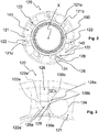
figure 7 is a perspective view of the hub offigure 1 seen from an observation point axially opposite to that offigure 1 , i.e. when observing its second flange in the foreground, and wherein respective spokes must be mounted on the first flange and respective spokes have been mounted on the second flange; -
figure 8 is an anterior front view of the second flange of the hub offigure 7 before the respective spokes are mounted; -
figure 9 is a perspective view of the hub offigure 1 in which respective spokes must be mounted on the first flange and two spokes have been mounted on the second flange; -
figure 10 is a side view of the hub offigure 1 before the spokes are mounted on the first flange and on the second flange; -
figure 11 is a perspective view of a second embodiment of a hub for a bicycle wheel in accordance with the present invention, such a hub comprising a first flange on which respective spokes must be mounted and a second flange on which respective spokes have been mounted, the hub being illustrated as it is seen when observing the second flange thereof in the foreground; -
figure 12 is an anterior front view of the second flange of the hub offigure 11 before the respective spokes are mounted; -
figure 13 is a perspective view of the hub offigure 11 seen from an observation point axially opposite to that offigure 11 , i.e. when observing the first flange thereof in the foreground, and wherein two spokes have been mounted on the second flange. - In all of the figures with
reference numeral 100 is wholly indicated a hub for a bicycle wheel, in different embodiments thereof. - In particular, it is a hub for a bicycle rear wheel.
- The
hub 100 comprises a substantially tubular body, or hub body, 102 inside which a shaft (not illustrated) is provided. Such a shaft is rotatably associated with thehub body 102 through suitable bearings (not illustrated) fitted onto the opposite free end portions of the shaft and it is intended to be connected, at such opposite free end portions, to the frame of the bicycle. - The
hub 100 has rotation axis X. - The
hub body 102 can be made of a metallic material, for example aluminum or alloys thereof, or of a composite material. The term "composite material" is used to indicate a material comprising structural fibers incorporated in a polymeric material. The structural fibers are preferably selected from the group comprising carbon fibers, glass fibers, boron fibers, aramid fibers, ceramic fibers and combinations thereof. The polymeric material can be thermoplastic or thermosetting. -
Spoke attachment flanges hub body 102. Theflanges hub body 102 or can be made (one or both) as distinct pieces from thehub body 102 to then be stably associated with thehub body 102. In the example illustrated herein, theflanges flange 220 is the one in accordance with the present invention. - A plurality of
respective spokes 12, described below, are mounted on theflanges - The
hub 100 can also comprise a brake disc (not illustrated). In this case, the brake disc is mounted on thehub 100 in an axially outer position with respect to theflange 120, on a suitableaxial mounting portion 150. - A freewheel (not illustrated) for supporting a sprocket assembly of the rear gearshift of the bicycle is associated with the
hub 100, in an axially outer position with respect to theflange 220. The freewheel is thus mounted on thehub 100 on the axially opposite side with respect to the axial mountingportion 150 of the brake disc. - Each
flange - With initial reference to
figures 1-6 , theflange 120 is described in detail. - In the non-limiting example illustrated in
figure 1 , thespokes 12 mounted on theflange 120 are straight-head spokes and, when they are mounted on the wheel, extend entirely in substantially radial planes, with more or less large camber angles. For example, the camber angle can be comprised between about 1° and about 15°, with reference to a plane orthogonal to the rotation axis X of thehub 100, which also corresponds to the rotation axis of theflange 120. - Each spoke 12 comprises an
enlarged head 12a and an elongated body or stem 12b (figures 1 ,4-6 ). - The
enlarged head 12a has a substantially circular cross section and preferably comprises conical or spherical surfaces. - The
flange 120 comprises anannular body 121 that extends coaxially to the rotation axis X of thehub 100. - The
annular body 121 comprises a radiallyouter surface 121a that, in the specific example illustrated herein, has a substantially cylindrical shape. - The
annular body 121 further comprises a radiallyinner portion 121b, also having a substantially cylindrical shape, which is associated with the respective free end portion of thehub body 102. - The
annular body 121 comprises a plurality ofseats 122 for housing theenlarged heads 12a of thespokes 12. - The
seats 122 are circumferentially equally spaced apart from each other. - In the non-limiting example illustrated in
figures 1-6 , sevenseats 122 are provided circumferentially spaced apart from each other by about 51°. In order not to complicate the reading offigures 1-6 , the reference numerals relative to theseats 122 and to the various portions of theseats 122 have been indicated only for some of the seven seats which are illustrated. - Each
seat 122 comprises anaccess hole 124 configured to allow afirst spoke 12 to be mounted in theseat 122. - The
access hole 124 is made on an anteriorfront face 121c of theannular body 121. Preferably, such afront face 121c is substantially flat and substantially orthogonal to the rotation axis X. - In the case in which the
hub 100 is intended to support a brake disc, the latter is arranged coaxially to the rotation axis X in a position axially adjacent to the aforementioned anteriorfront face 121c. - In the non-limiting example illustrated in
figures 1-6 , theaccess hole 124 extends along a substantially axial direction and has a substantially cylindrical shape. - The
access hole 124 can be a through hole (like in the non-limiting example illustrated infigures 1-6 ) or a blind hole. - As explained below, the
access hole 124 can be made through a ball nose milling cutter or through a front cylindrical cutter or a drill bit. - The
access hole 124 has dimensions such as to allow the insertion of theenlarged head 12a of afirst spoke 12. - Each
seat 122 further comprises an outlet opening, which in the specific example illustrated herein is defined by aslit 126, configured to hold theenlarged head 12a in theseat 122 when thespoke 12 is tensioned. - The
slit 126 is made so as to open onto the radiallyouter surface 121a of theannular body 121 and onto the anteriorfront face 121c. - In the non-limiting example illustrated in
figures 1-6 , theslit 126 extends along a substantially radial direction. - The
slit 126 has a substantially constant circumferential width in the radial direction and such as to allow thestem 12b of thespoke 12 to be housed. - As explained below, such a
slit 126 can be made through a cylindrical cutter. - As more clearly illustrated in the enlargement of
figure 3 , theaccess hole 124 and theslit 126 are circumferentially spaced apart from each other and are connected to one another through aconnection channel 128. - In particular, the center of the
access hole 124 and the central axis of theslit 126 are angularly spaced apart from each other, preferably by an angle comprised between 5° and 60°, the extreme values being included. For example, in the case in which theflange 120 is configured for the attachment of seven spokes extending along respective radial directions, the aforementioned angle is equal to 11°. - The
connection channel 128 is made on the anteriorfront face 121c and, in the non-limiting example illustrated infigures 1-6 , extends along a substantially circumferential direction between theaccess hole 124 and a radiallyinner end portion 126a of theslit 126. - As illustrated in
figure 3 , theconnection channel 128 comprises a firstfront abutment surface 130a and a secondfront abutment surface 130b, arranged on radially opposite sides of theconnection channel 128. In particular, the firstfront abutment surface 130a is arranged in a radially inner position with respect to the secondfront abutment surface 130b. - The first
front abutment surface 130a extends up to theslit 126, starting from theaccess hole 124. The secondfront abutment surface 130b extends up to close to theslit 126, again starting from theaccess hole 124. - Each
front abutment surface enlarged head 12a in the case of detensioning of thespoke 12, thus preventing the axial exit of theenlarged head 12a from theslit 126. - Again with reference to
figure 3 , eachseat 122 comprises, in a radially inner position with respect to theslit 126, a substantially sphericalfirst seat portion 122a having a surface that, preferably, matches the conical or spherical surfaces of theenlarged head 12a of thespoke 12. As explained below, such afirst seat portion 122a can be made through a ball nose milling cutter. - Each
seat portion 122a has a radially innerfirst surface part 122a' that is substantially spherical and a radially outer secondspherical surface part 122a". - The first
front abutment surface 130a extends up to thefirst seat portion 122a. In particular, the firstfront abutment surface 130a joins to thefirst surface part 122a' of thefirst seat portion 122a, whereas theslit 126 separates the secondfront abutment surface 130b from the secondspherical surface part 122a". - Again with reference to
figure 3 , theconnection channel 128 comprises afirst channel portion 128a having a first radial width lower than or equal to that of theaccess hole 124 and, in a position axially adjacent to thefirst channel portion 128a, on the side facing towards thefront face 121c of theannular body 121, asecond channel portion 128b having a radial width smaller than the first radial width and such as to allow the passage of thestem 12b of the spoke. - The
first channel portion 128a is substantially spherical. - The
first abutment surface 130a and thesecond abutment surface 130b join thefirst channel portion 128a to thesecond channel portion 128b. - As explained below, the
first channel portion second channel portion 128b can be made through a cylindrical cutter. - As illustrated in
figure 2 , theannular body 121 further comprises a plurality of weight-reduction throughopenings 140, each of which is arranged between two circumferentiallyconsecutive seats 122. - As illustrated in
figure 10 , a plurality of weight-reducingnon-through recesses 142 is provided on the radiallyouter surface 121a of theannular body 121, each of which is arranged between two circumferentiallyconsecutive seats 122, preferably at a respective weight-reducing throughopening 140. - A
hub 100 of the type discussed above can be manufactured with the manufacturing method described below. Reference is made in particular to the case in which thehub 100 or at least theflange 120 are made of a metallic material, such as aluminum or alloys thereof. - Once the
flange 120 has been made, a plurality ofseats 122 for housing theenlarged heads 12a of thespokes 12 are formed on theannular body 121 thereof. - Each of the
seats 122 is formed by making theaccess hole 124, theconnection channel 128 and theslit 126 as described below. - The
access hole 124 is made on thefront face 121c of theannular body 121 using a first tool (not illustrated). Such a first tool can be a ball nose milling cutter, a front cylindrical cutter or a drill bit. - Through a cylindrical cutter the
slit 126 is made on the radiallyouter surface 121a and on thefront face 121c of theannular body 121 and thesecond channel portion 128b is made on thefront face 121c. - Thereafter, through a ball nose milling cutter the
first seat portion 122a and thefirst channel portion 128a are made. Theconnection channel 128 is thus obtained. - Such a
connection channel 128 extends from theaccess hole 124 along a direction which is different from the radial direction and from the axial direction. In the non-limiting example of thehub 100 illustrated infigures 1-6 , theconnection channel 128 extends along a circumferential direction. - The ball nose milling cutter defines the two
front abutment surfaces connection channel 128. - The mounting of the
spokes 12 on theflange 120 takes place as described below. Reference is made tofigures 4-6 . - Initially, the
enlarged head 12a of aspoke 12 is inserted in theaccess hole 124, keeping thespoke 12 substantially parallel to the rotation axis X of the hub 124 (figure 4 ). - The
spoke 12 is subsequently made to slide inside theconnection channel 128 until theslit 126 is reached, in particular thefirst seat portion 122a, corresponding to the radiallyinner end portion 126a of the slit 126 (figure 5 ). During the sliding of thespoke 12 in theconnection channel 128, theenlarged head 12a of thespoke 12 slides in thefirst channel portion 128a whereas thestem 12b of thespoke 12 slides in thesecond channel portion 128b and exits from thefront face 121c of theannular body 121 according to a direction substantially parallel to the rotation axis X of thehub 124. - Once the
seat portion 122a has been reached, thestem 12b of thespoke 12 is rotated by about 90° so as to be positioned in theslit 126 and then be able to proceed with the tensioning of the spoke 12 (figure 6 ). - Following the tensioning of the
spoke 12, theenlarged head 12a thereof goes into abutment against the radially outer portion of thefirst seat portion 122a. - The hub of the invention can also be used in a front wheel of the bicycle, possibly also provided with a brake disc.
- In the non-limiting example described herein and illustrated in
figure 1 , theflange 220 is different from theflange 120 and has the features described below with reference tofigures 7-10 . - Alternatively, the
flange 220 can have the features described below with reference tofigures 11-13 . - The
spokes 12 mounted on theflange 220 offigures 7-10 and on theflange 220 offigures 11-13 are also straight-head spokes. In this case, however, when thespokes 12 are mounted on the wheel, they extend entirely along non-radial directions, substantially orthogonal to the rotation axis X of thehub 100, with more or less large camber angles. For example, the camber angle can be comprised between about 1° and about 15°, with reference to a plane orthogonal to the rotation axis X of thehub 100, which also corresponds to the rotation axis of theflange 220. - The
aforementioned spokes 12 have a shape identical to that of thespokes 12 mounted in theflange 120 and therefore they will not be described again. However, in the non-limiting examples shown in the figures, thespokes 12 mounted in theflange 220 have a longitudinal extension greater than that of thespokes 12 mounted in theflange 120. - The
flange 220 offigures 7-10 , like that offigures 11-13 , comprises anannular body 221 that extends coaxially to the rotation axis X of thehub 100. In the non-limiting examples shown in the figures, the radial extension of theannular body 221 of theflange 220 is greater than that of theannular body 121 of theflange 120. - The
annular body 221 comprises a radiallyouter surface 221a that, in the specific example illustrated herein, has a substantially cylindrical shape. - The
annular body 221 further comprises a radiallyinner portion 221b, also having a substantially cylindrical shape, which is associated with the respective free end portion of thehub body 102. - The
annular body 221 of theflange 220 offigures 7-10 comprises a plurality offirst seats 222a for housing theenlarged heads 12a of a first plurality ofspokes 12. - The
annular body 221 of theflange 220 offigures 7-10 further comprises a plurality ofsecond seats 222b for housing theenlarged heads 12a of a second plurality ofspokes 12. - In the non-limiting example shown in
figures 7-10 , each of theseats seats 122 of theannular body 121 of theflange 120. - In the illustrated example fourteen
seats seats 222a and sevenseats 222b) are provided in total. They are circumferentially equally spaced apart from each other along theannular body 221. In order not to complicate the reading offigures 7-10 , the reference numerals relative to theaforementioned seats such seats - Each
first seat 222a comprises afirst access opening 224a configured to allow the insertion of theenlarged head 12a of afirst spoke 12 in theseat 222a. - The
access opening 224a is made on an anteriorfront face 221c of theannular body 221. Preferably, such an anteriorfront face 221c is substantially flat and substantially orthogonal to the rotation axis X. - In the case in which a freewheel (not illustrated) is associated with the
hub 100 offigures 7-13 or offigures 1-6 , it is arranged coaxially to the rotation axis X in a position axially adjacent to the aforementioned anteriorfront face 221c. - In the non-limiting example illustrated in
figures 7-10 , theaccess opening 224a extends along a substantially axial direction and has a substantially cylindrical shape. - The
access opening 224a can be a through opening (like in the preferred and non-limiting example illustrated infigures 7-10 ) or a blind opening. Theaccess opening 224a can be made through a drill bit, a front cylindrical cutter or a ball nose milling cutter. - The
access opening 224a has dimensions such as to allow the insertion of theenlarged head 12a of aspoke 12. - Each
seat 222a further comprises anoutlet opening 226a configured to allow astem 12b of the first spoke 12 to exit from theseat 222a. - The
outlet opening 226a is made on the radiallyouter surface 221a of theannular body 221. - The
outlet opening 226a is preferably defined by a hole of dimensions such as to allow the passage of thestem 12b of thespoke 12. In particular, such a hole is cylindrical and is arranged in a position adjacent to the anteriorfront face 221c. - The aforementioned hole can be made through a drill bit or a front cylindrical cutter.
- Alternatively, the
outlet opening 226a can be defined by a slot, so as to facilitate the passage of thestem 12b. - As clearly illustrated in
figure 8 , theaccess opening 224a and theoutlet opening 226a are connected to one another through aconnection channel 228a. - In the non-limiting example illustrated in
figures 7-10 , theconnection channel 228a extends from theaccess opening 224a along a non-radial rectilinear direction. - The
connection channel 228a defines on the anteriorfront face 221c aslit 229a that extends from the access opening 224a towards theoutlet opening 226a without reaching the radiallyouter surface 221a. In this way, theflange 220 has, between theaccess opening 224a and theoutlet opening 226a, afirst bridge 230a defined in part on the radiallyouter surface 221a and in part on the anteriorfront face 221c. Thefirst bridge 230a has a substantially circumferential extension and prevents the axial exit of the first spoke 12 from theconnection channel 228a, in the case of detensioning thereof. - The
slit 229a can be made through a cylindrical cutter. - Each
access opening 224a comprises, at theconnection channel 228a, anabutment surface 231a for theenlarged head 12a of the first spoke 12 when the first spoke 12 is tensioned. - The
abutment surface 231a is substantially spherical. - The
enlarged head 12a of the first spoke 12 preferably comprises conical or spherical surfaces which match theabutment surface 231a. Such anabutment surface 231a can be made through a ball nose milling cutter. - The
annular body 221 further comprises anon-through recess 232a made on the anteriorfront face 221c in a position adjacent to the first access opening 224a. Thenon-through recess 232a is made on the substantially opposite side to theconnection channel 228a, so as to have a sufficient maneuvering space on the anteriorfront face 221c of theflange 220 to allow the insertion of the first spoke 12 in theseat 222a. - Each
second seat 222b comprises a second access opening configured to allow the insertion of theenlarged head 12a of asecond spoke 12 in theseat 222b. Such an access opening is also made on the anteriorfront face 221c of theannular body 221. - In the non-limiting example illustrated in
figures 7-10 , the second access opening coincides with the first access opening 224a, i.e. the first and the second access openings are defined by a single access opening extending from the first anteriorfront face 221c. Hereinafter, therefore, when reference will be made to the second access opening thesame reference numeral 224a used for the first access opening will be used. - In an alternative embodiment that is not illustrated, the second access opening is distinct from the first access opening 224a, whilst still having the same features described above with respect to the first access opening 224a.
- Each
seat 222b further comprises anoutlet opening 226b configured to allow thestem 12b of the second spoke 12 to exit from theseat 222b. - The
outlet opening 226b is made on the radiallyouter surface 221a of theannular body 221. - As clearly illustrated in
figure 10 , theoutlet opening 226b is defined by a slot extending along a substantially axial direction and having a circumferential dimension such as to allow the passage of thestem 12b of thesecond spoke 12. - Such a slot can be made through a front cylindrical cutter.
- In the case in which the
outlet opening 226a is defined by a slot, it preferably has dimensions smaller than those of the slot that defines theoutlet opening 226b. - As illustrated in
figure 8 , theaccess opening 224a and theoutlet opening 226a are connected to one another through aconnection channel 228b. - In the non-limiting example illustrated in
figures 7-10 , theconnection channel 228b extends from theaccess opening 224a along a non-radial rectilinear direction, on a side substantially opposite with respect to that where theconnection channel 228a extends. The directions of extension of theconnection channel 228a and of theconnection channel 228b are angularly offset by an angle comprised in the range between 100° and 180°, the extreme values being included. For example, the aforementioned angle can be equal to about 140°. - The
connection channel 228b defines on the anteriorfront face 221c aslit 229b that extends from the access opening 224a towards theoutlet opening 226b without reaching the radiallyouter surface 221a. In this way, between theaccess opening 224a and theoutlet opening 226b theflange 220 has asecond bridge 230b also defined in part on the radiallyouter surface 221a and in part on the anteriorfront face 221c. Thesecond bridge 230b has a substantially circumferential extension and prevents the axial exit of the second spoke 12 from theconnection channel 228b, in the case of detensioning thereof. - The
slit 229b can be made through a cylindrical cutter. - In the example of
figures 7-10 , thebridges flange 220 at the connection edge between the anteriorfront face 221c and the radiallyouter surface 221a of theflange 220. - Each access opening 224a further comprises, at the
connection channel 228b, anabutment surface 231b for theenlarged head 12a of the second spoke 12 when the second spoke 12 is tensioned. - The
abutment surface 231b for theenlarged head 12a of the second spoke 12 is substantially spherical. - The
enlarged head 12a of the second spoke 12 preferably comprises conical or spherical surfaces matching theabutment surface 231b. Such anabutment surface 231b can be made through a ball nose milling cutter. - As is clearly illustrated in
figure 8 , theconnection channel 228b is at least in part made in therecess 232a. - The
first spokes 12 mounted in thefirst seats 222a are substantially identical to thesecond spokes 12 mounted in thesecond seats 222b. - The
annular body 221 further comprises a plurality of weight-reducing throughopenings 240, each of which is arranged between two circumferentiallyconsecutive access openings 224a. - On the radially
outer surface 221a of theannular body 221 a plurality of weight-reducingnon-through recesses 242 are provided, each of which is arranged between anoutlet opening 226a and anoutlet opening 226b and is arranged at a respective access opening 224a. - The mounting of the
spokes 12 on theflange 220 of thehub 100 discussed above takes place as described below. - The
spokes 12 are inserted in theseats front face 221c. - In particular, thanks to the provision of the
non-through recess 232a, thefirst spokes 12 are inserted in theseats 222a making an end portion of thestem 12b of thespoke 12, opposite to the end portion where theenlarged head 12a is provided, enter into theaccess opening 224a and making it exit from theoutlet opening 226a, until theenlarged head 12a goes into abutment against theabutment surface 231a. - Thanks to the provision of the
outlet opening 226b in the form of a slot, thesecond spokes 12 are inserted in theseats 222b making an end portion of thestem 12b of thespoke 12, opposite to the end portion where theenlarged head 12a is provided, enter into theaccess opening 224a and making it exit from theoutlet opening 226b, until theenlarged head 12a goes into abutment against theabutment surface 231b. - With reference to
figures 11-13 , theannular body 221 of theflange 220 illustrated herein comprises a plurality ofseats 222a for housing theenlarged heads 12a of a first plurality ofspokes 12. Such seats are totally identical to those described above with reference tofigures 7-10 and will not be described again. - The
annular body 221 of theflange 220 offigures 11-13 also comprises, instead of theseats 222b described above with reference tofigures 7-10 , a plurality ofseats 222c for housing theenlarged heads 12a of a second plurality ofspokes 12. - The
seats 222c differ from theseats 222b and are described below. - In the non-limiting example shown in
figures 11-13 , each of theseats seats 122 of theannular body 121 of theflange 120. - In the illustrated example fourteen
seats seats 222a and sevenseats 222c) are provided in total. They are arranged circumferentially equally spaced apart from each other along theannular body 221. In order not to complicate the reading offigures 11-13 , the reference numerals relative to theaforementioned seats such seats - The
annular body 221 of theflange 220 offigures 11-13 also comprises anon-through recess 232a made on the anteriorfront face 221c in a position adjacent to the access opening 224a of theseat 222a. Thenon-through recess 232a is totally analogous to thenon-through recess 232a described above with reference to theflange 220 illustrated infigures 7-10 . - Each
seat 222c comprises anaccess opening 224c configured to allow asecond spoke 12 to be mounted in theseat 222c. - The
access opening 224c is made on arear front face 221d of theannular body 221. Preferably, such arear front face 221d is substantially flat and substantially orthogonal to the rotation axis X. - In the non-limiting example illustrated in
figures 11-13 , theaccess opening 224c extends along a substantially axial direction and has a substantially cylindrical shape. - The
access opening 224c can be a through opening (like in the non-limiting example illustrated infigures 11-13 and as specified below) or a blind opening. Theaccess opening 224c can be made through a drill bit, a front cylindrical cutter or a ball nose milling cutter. - The
access opening 224c has dimensions such as to allow the insertion of theenlarged head 12a of thesecond spoke 12. - In the non-limiting example illustrated in
figures 11-13 , the access opening 224c and theaccess opening 224a are defined by a single access through opening extending from therear front face 221d to the anteriorfront face 221c. - Each
seat 222c further comprises anoutlet opening 226c configured to allow astem 12b of the second spoke 12 to exit from theseat 222c. - The
outlet opening 226c is made on the radiallyouter surface 221a of theannular body 221. - The
outlet opening 226c is preferably defined by a hole having dimensions such as to allow the passage of thestem 12b of thesecond spoke 12. In particular, such a hole is cylindrical and is arranged in a position adjacent to therear front face 221d. - Alternatively, the
outlet opening 226c can be defined by a slot, so as to facilitate the passage of thestem 12b. - The
outlet opening 226c can be made through a drill bit or, particularly in the case in which it is defined by a slot, by a front cylindrical cutter. - As clearly illustrated in
figure 12 , the access opening 224c and theoutlet opening 226c are connected to one another through aconnection channel 228c. - In the non-limiting example illustrated in
figures 11-13 , theconnection channel 228c extends from the access opening 224c along a non-radial rectilinear direction. Theconnection channel 228c extends, relative to the access opening 224c, from a substantially opposite side with respect to that where theconnection channel 228a extends. The directions of extension of theconnection channel 228a and of theconnection channel 228c are angularly offset by an angle comprised within the range between 100° and 180°, the extreme values being included. - The
connection channel 228a defines on therear front face 221d aslit 229c that extends from the access opening 224c towards theoutlet opening 226c without reaching the radiallyouter surface 221a. In this way, between the access opening 224c and theoutlet opening 226c theflange 220 has abridge 230c defined in part on the radiallyouter surface 221a and in part on therear front face 221d. Thebridge 230c has a substantially circumferential extension and prevents the axial exit of the second spoke 12 from theconnection channel 228c, in the case of the detensioning thereof. - In the example of
figures 11-13 , thebridges 230a define in the anteriorfront face 221c of the flange 220 a single annular bridge arranged on theflange 220 at the connection edge between the anteriorfront face 221c and the radiallyouter surface 221a of theflange 220 and thebridges 230b define in therear front face 221d of the flange 220 a single annular bridge arranged on theflange 220 at the connection edge between therear front face 221d and the radiallyouter surface 221a of theflange 220. - The
slit 229c can be made through a cylindrical cutter. - Each access opening 224c comprises, at the
connection channel 228c, anabutment surface 231c for theenlarged head 12a of the second spoke 12 when the second spoke 12 is tensioned. - The
abutment surface 231c is substantially spherical. - The
enlarged head 12a of the second spoke 12 preferably comprises conical or spherical surfaces matching theabutment surface 231c. Such anabutment surface 231c can be made through a ball nose milling cutter. - The
annular body 221 comprises anon-through recess 232c made on therear front face 221d in a position adjacent to the access opening 224c. Thenon-through recess 232c is made on substantially the opposite side to theconnection channel 228c, so as to have a sufficient maneuvering space on therear front face 221d of theflange 220 to allow the insertion of the second spoke 12 in theseat 222c. - The
first spokes 12 mounted in thefirst seats 222a are substantially identical to thesecond spokes 12 mounted in thethird seats 222c. - The
annular body 221 further comprises a plurality of weight-reducing throughopenings 240, each of which is arranged between two circumferentiallyconsecutive access openings 224c. - Similarly to the flange of
figures 7-10 , also on the radiallyouter surface 221a of theannular body 221 of the flange offigures 11-13 a plurality of weight-reducingnon-through recesses 242 are provided, each of which is arranged between anoutlet opening 226a and anoutlet opening 226c and is arranged at a respective access opening 224a (or 224c). - The mounting of the
spokes 12 on theflange 220 of thehub 100 offigures 11-13 takes place as described below. - Thanks to the provision of the
non-through recess 232a on the anteriorfront face 221c of theflange 220, thefirst spokes 12 are inserted in theseats 222a in a totally analogous manner to what has been stated above with reference to the mounting of thespokes 12 in theseats 222a of theflange 220 offigures 7-10 . - Thanks to the provision of the
non-through recess 232c on therear front face 221d of theflange 220, thesecond spokes 12 are inserted in theseats 222c making an end portion of thestem 12b of thespoke 12, opposite to the end portion where theenlarged head 12a is provided, enter into the access opening 224c and making it exit from theoutlet opening 226c, until theenlarged head 12a goes into abutment against theabutment surface 231c. - In the case in which the
hub 100 is intended to be used in a front wheel of the bicycle, theflange 220 is mounted on thehub 100 on the same side in which the brake disc is mounted. - In an embodiment that is not illustrated of the
hub 100 of the present invention, theflange 120 is identical to one of theflanges 220 described above with reference tofigures 7-10 or 11-13. - Of course, those skilled in the art, in order to satisfy specific and contingent requirements, can bring numerous modifications and variants to the present invention as described above, all of them being in any case within the scope of protection defined by the following claims.
Claims (15)
- Spoke attachment flange (120) for a hub (100) for a bicycle wheel, said flange (120) comprising an annular body (121) extending coaxially to a rotation axis (X), said annular body (121) comprising a plurality of seats (122) for housing enlarged heads (12a) of spokes (12), each of said seats (122) comprising:- an access hole (124) made on a front face (121c) of said annular body (121) and configured to allow the insertion of the enlarged head (12a) of a spoke (12) in said seat (122);- an outlet opening (126) that opens onto a radially outer surface (121a) of said annular body (121) and onto said front face (121c) and configured to hold said enlarged head (12a) in said seat (122) when the spoke (12) is tensioned;
characterized in that said access hole (124) and said outlet opening (126) are circumferentially spaced apart from each other and are connected to one another through a connection channel (128) made on said front face (121c) and comprising, at least close to or at said outlet opening (126), at least one front abutment surface (130a, 130b) configured to go into abutment against said enlarged head (12a) in the case of detensioning of the spoke (12), thus preventing an axial exit of said enlarged head (12a) from said outlet opening (126). - Flange (120) according to claim 1, wherein said connection channel (128) comprises a first front abutment surface (130a) extending up to said outlet opening (126).
- Flange (120) according to claim 1 or 2, wherein said connection channel (128) comprises a second front abutment surface (130b) extending up to close to said outlet opening (126).
- Flange (120) according to claim 3 when depending on claim 2, wherein said first front abutment surface (130a) is arranged in a radially inner position with respect to said second front abutment surface (130b).
- Flange (120) according to any one of the previous claims, wherein said connection channel (128) extends along a substantially circumferential direction between said access hole (122) and a radially inner end portion (126a) of said outlet opening (126).
- Flange (120) according to claim 5, wherein said seat (122) comprises, in a radially inner position with respect to said outlet opening (126), a substantially spherical first seat portion (122a).
- Flange (120) according to any one of the previous claims, wherein said outlet opening (126) extends along a substantially radial direction.
- Flange (120) according to any one of the previous claims, wherein said access hole (124) extends along a substantially axial direction.
- Flange (120) according to any one of the previous claims, wherein said access hole (124) has a substantially cylindrical shape.
- Flange (120) according to any one of the previous claims, wherein said connection channel (128) comprises a first channel portion (128a) having a first radial width substantially equal to that of said access hole (124) and, in a position axially adjacent to said first channel portion (128a), a second channel portion (128b) having a radial width smaller than said first radial width and such as to allow the passage of a stem (12b) of the spoke (12).
- Flange (120) according to claim 10, wherein said first channel portion (128a) is substantially spherical.
- Flange (120) according to claim 7, wherein said outlet opening (126) has a substantially constant circumferential width in the radial direction and such as to allow a stem (12b) of the spoke (12) to be housed therein.
- Method for mounting a spoke (12) on a flange (120) of a hub (100) for a bicycle wheel, said spoke (12) comprising an enlarged head (12a) and a stem (12b), the method comprising the steps of:- inserting said enlarged head (12a) in an access hole (124) made on a front face of the flange (120);- moving said spoke from said access hole (124) until an outlet opening (126) that is circumferentially spaced apart from said access hole (124) and that opens onto a radially outer surface (121a) and onto said front face (121c) of said flange (120) is reached, said movement being carried out by acting on said stem (12b) and making said enlarged head (12a) slide along a connection channel (128) made on said front face (121c) and connecting said access hole (124) to said outlet opening (126);- when said enlarged head (12A) has reached said outlet opening (126), rotating said spoke (12) until said stem (12b) is housed in said outlet opening (126);- tensioning the spoke (12).
- Method for manufacturing a hub (100) for a bicycle wheel, comprising the steps of:- making a flange (120) having an annular body (121) extending coaxially to a rotation axis (X);- forming on said annular body (121) a plurality of seats (122) for housing enlarged heads (12a) of spokes (12), wherein each of said seats (122) is formed through the following steps:- making on a front face (121c) of said annular body (121) an access hole (124) having dimensions such as to allow the insertion of an enlarged head (12a) of a spoke (12) in said seat (122);- making in said annular body (121)a connection channel (128) extending from said access hole (124) along a non-radial direction and having at least one front abutment surface (130a, 130b) configured to go into abutment against said enlarged head (12a) in the case of detensioning of the spoke (12);- making an outlet opening (126) that opens onto a radially outer surface (121a) of said annular body (121) and onto said front face (121c) until said connection channel (128) is reached, said outlet opening (126) being configured to hold said enlarged head (12a) in said seat (122) when the spoke (12) is tensioned.
- Method according to claim 14, wherein said connection channel (128) is made through a ball nose milling cutter.
Applications Claiming Priority (1)
| Application Number | Priority Date | Filing Date | Title |
|---|---|---|---|
| IT102018000004988A IT201800004988A1 (en) | 2018-05-02 | 2018-05-02 | Spoke attachment flange for a bicycle wheel hub, method for mounting a spoke to the flange and hub manufacturing method |
Publications (1)
| Publication Number | Publication Date |
|---|---|
| EP3564044A1 true EP3564044A1 (en) | 2019-11-06 |
Family
ID=62816991
Family Applications (1)
| Application Number | Title | Priority Date | Filing Date |
|---|---|---|---|
| EP19170402.2A Withdrawn EP3564044A1 (en) | 2018-05-02 | 2019-04-19 | Spoke attachment flange for a hub for a bicycle wheel, method for mounting a spoke on the flange and method for manufacturing the hub |
Country Status (3)
| Country | Link |
|---|---|
| US (1) | US10737529B2 (en) |
| EP (1) | EP3564044A1 (en) |
| IT (1) | IT201800004988A1 (en) |
Families Citing this family (2)
| Publication number | Priority date | Publication date | Assignee | Title |
|---|---|---|---|---|
| US11571929B2 (en) | 2020-06-17 | 2023-02-07 | Shimano Inc. | Wheel hub |
| US11904630B1 (en) | 2023-06-06 | 2024-02-20 | Rolf Dietrich | Bicycle hub and spoke arrangement |
Citations (5)
| Publication number | Priority date | Publication date | Assignee | Title |
|---|---|---|---|---|
| US5626401A (en) * | 1994-05-17 | 1997-05-06 | Innovative Bicycle Components Company | Spoked wheel hub |
| EP1685979A1 (en) * | 2005-01-28 | 2006-08-02 | Campagnolo S.r.l. | Bicycle wheel and spoke and hub body therefor |
| EP1923232A1 (en) * | 2006-11-20 | 2008-05-21 | CAMPAGNOLO S.r.l. | Hub for a bicycle wheel and bicycle wheel comprising such a hub |
| US7621601B2 (en) | 2007-11-21 | 2009-11-24 | Tien Hsin Industries Co., Ltd. | Bicycle hub |
| US20170305189A1 (en) | 2016-04-26 | 2017-10-26 | Dt Swiss Inc. | Hub and wheel |
Family Cites Families (9)
| Publication number | Priority date | Publication date | Assignee | Title |
|---|---|---|---|---|
| US5795036A (en) * | 1995-05-26 | 1998-08-18 | Campagnolo S.R.L. | Bicycle rear wheel |
| DE19724327B4 (en) * | 1997-06-10 | 2009-01-29 | Sram Deutschland Gmbh | Hub for a spoked wheel |
| DE602004012378T2 (en) * | 2004-01-27 | 2009-04-23 | Campagnolo S.R.L. | Spoke for bicycle and bicycle wheel containing such a spoke and manufacturing method for such spoke |
| ITMI20062215A1 (en) | 2006-11-20 | 2008-05-21 | Campagnolo Srl | BICYCLE RADIUS WHEEL AND HUB FOR SUCH WHEEL AND WHEEL ASSEMBLY METHOD |
| US20100322546A1 (en) * | 2009-06-22 | 2010-12-23 | Jeroen Bosboom | Freehub ball bearing carrier |
| DE102011015962B4 (en) * | 2011-04-04 | 2016-05-25 | Dt Swiss Ag | Hub for a bicycle |
| ITMI20121042A1 (en) * | 2012-06-15 | 2013-12-16 | Campagnolo Srl | BICYCLE WHEEL AND ITS MANUFACTURING PROCEDURE |
| US9815322B2 (en) | 2015-01-19 | 2017-11-14 | Shimano Inc. | Bicycle hub and bicycle wheel assembly |
| DE102016107755A1 (en) | 2016-04-26 | 2017-10-26 | Dt Swiss Ag | Hub and impeller |
-
2018
- 2018-05-02 IT IT102018000004988A patent/IT201800004988A1/en unknown
-
2019
- 2019-04-19 EP EP19170402.2A patent/EP3564044A1/en not_active Withdrawn
- 2019-04-30 US US16/399,065 patent/US10737529B2/en active Active
Patent Citations (5)
| Publication number | Priority date | Publication date | Assignee | Title |
|---|---|---|---|---|
| US5626401A (en) * | 1994-05-17 | 1997-05-06 | Innovative Bicycle Components Company | Spoked wheel hub |
| EP1685979A1 (en) * | 2005-01-28 | 2006-08-02 | Campagnolo S.r.l. | Bicycle wheel and spoke and hub body therefor |
| EP1923232A1 (en) * | 2006-11-20 | 2008-05-21 | CAMPAGNOLO S.r.l. | Hub for a bicycle wheel and bicycle wheel comprising such a hub |
| US7621601B2 (en) | 2007-11-21 | 2009-11-24 | Tien Hsin Industries Co., Ltd. | Bicycle hub |
| US20170305189A1 (en) | 2016-04-26 | 2017-10-26 | Dt Swiss Inc. | Hub and wheel |
Also Published As
| Publication number | Publication date |
|---|---|
| US10737529B2 (en) | 2020-08-11 |
| IT201800004988A1 (en) | 2019-11-02 |
| US20190337326A1 (en) | 2019-11-07 |
Similar Documents
| Publication | Publication Date | Title |
|---|---|---|
| EP1923232A1 (en) | Hub for a bicycle wheel and bicycle wheel comprising such a hub | |
| US6409282B1 (en) | Bicycle hub | |
| US7530645B2 (en) | Bicycle wheel securing structure | |
| CN102632763B (en) | Bicycle rim | |
| US7341316B2 (en) | Bicycle hub assembly | |
| EP1614548B1 (en) | Hub body for a bicycle wheel and hub comprising such a hub body | |
| EP2492112B1 (en) | Spoke attachment structure | |
| EP3564044A1 (en) | Spoke attachment flange for a hub for a bicycle wheel, method for mounting a spoke on the flange and method for manufacturing the hub | |
| EP3564043B1 (en) | Spoke attachment flange for a hub for a bicycle wheel and method for mounting a spoke on the flange | |
| US9604495B2 (en) | Hub for a bicycle | |
| EP1939013B1 (en) | Hub for a spoked bicycle wheel and related spoked wheel | |
| US9004771B2 (en) | Bicycle bottom bracket | |
| US7621601B2 (en) | Bicycle hub | |
| EP2390111B1 (en) | Bicycle wheel spoke assembly | |
| US20080309152A1 (en) | Wheel including a rim, a hub, and a device for coupling the rim to the hub | |
| US7360847B2 (en) | Bicycle hub | |
| US5372407A (en) | Laced wheel hub | |
| CZ20021809A3 (en) | Bicycle wheel hub | |
| TW201739635A (en) | Hub and wheel | |
| EP3476620B1 (en) | Spoke-attachment flange for a hub for a bicycle wheel and hub for a bicycle wheel including such a flange | |
| JPH09220903A (en) | Two-piece wheel for automobile and its manufacturing method | |
| HK1231022B (en) | Spoke wheel rim |
Legal Events
| Date | Code | Title | Description |
|---|---|---|---|
| PUAI | Public reference made under article 153(3) epc to a published international application that has entered the european phase |
Free format text: ORIGINAL CODE: 0009012 |
|
| STAA | Information on the status of an ep patent application or granted ep patent |
Free format text: STATUS: THE APPLICATION HAS BEEN PUBLISHED |
|
| AK | Designated contracting states |
Kind code of ref document: A1 Designated state(s): AL AT BE BG CH CY CZ DE DK EE ES FI FR GB GR HR HU IE IS IT LI LT LU LV MC MK MT NL NO PL PT RO RS SE SI SK SM TR |
|
| AX | Request for extension of the european patent |
Extension state: BA ME |
|
| STAA | Information on the status of an ep patent application or granted ep patent |
Free format text: STATUS: REQUEST FOR EXAMINATION WAS MADE |
|
| 17P | Request for examination filed |
Effective date: 20200311 |
|
| RBV | Designated contracting states (corrected) |
Designated state(s): AL AT BE BG CH CY CZ DE DK EE ES FI FR GB GR HR HU IE IS IT LI LT LU LV MC MK MT NL NO PL PT RO RS SE SI SK SM TR |
|
| GRAP | Despatch of communication of intention to grant a patent |
Free format text: ORIGINAL CODE: EPIDOSNIGR1 |
|
| STAA | Information on the status of an ep patent application or granted ep patent |
Free format text: STATUS: GRANT OF PATENT IS INTENDED |
|
| RIC1 | Information provided on ipc code assigned before grant |
Ipc: B60B 27/02 20060101ALI20200701BHEP Ipc: B60B 1/00 20060101ALI20200701BHEP Ipc: B60B 1/04 20060101AFI20200701BHEP |
|
| INTG | Intention to grant announced |
Effective date: 20200722 |
|
| STAA | Information on the status of an ep patent application or granted ep patent |
Free format text: STATUS: THE APPLICATION IS DEEMED TO BE WITHDRAWN |
|
| 18D | Application deemed to be withdrawn |
Effective date: 20201202 |