EP3563273B1 - Augmented reality-based ply layups on a composite part layup tool - Google Patents
Augmented reality-based ply layups on a composite part layup tool Download PDFInfo
- Publication number
- EP3563273B1 EP3563273B1 EP18783165.6A EP18783165A EP3563273B1 EP 3563273 B1 EP3563273 B1 EP 3563273B1 EP 18783165 A EP18783165 A EP 18783165A EP 3563273 B1 EP3563273 B1 EP 3563273B1
- Authority
- EP
- European Patent Office
- Prior art keywords
- ply
- layup
- headset
- composite part
- tool
- Prior art date
- Legal status (The legal status is an assumption and is not a legal conclusion. Google has not performed a legal analysis and makes no representation as to the accuracy of the status listed.)
- Active
Links
Images



Classifications
-
- G—PHYSICS
- G06—COMPUTING OR CALCULATING; COUNTING
- G06F—ELECTRIC DIGITAL DATA PROCESSING
- G06F30/00—Computer-aided design [CAD]
- G06F30/10—Geometric CAD
- G06F30/17—Mechanical parametric or variational design
-
- G—PHYSICS
- G06—COMPUTING OR CALCULATING; COUNTING
- G06F—ELECTRIC DIGITAL DATA PROCESSING
- G06F30/00—Computer-aided design [CAD]
-
- G—PHYSICS
- G02—OPTICS
- G02B—OPTICAL ELEMENTS, SYSTEMS OR APPARATUS
- G02B27/00—Optical systems or apparatus not provided for by any of the groups G02B1/00 - G02B26/00, G02B30/00
- G02B27/01—Head-up displays
- G02B27/017—Head mounted
- G02B27/0172—Head mounted characterised by optical features
-
- G—PHYSICS
- G02—OPTICS
- G02B—OPTICAL ELEMENTS, SYSTEMS OR APPARATUS
- G02B27/00—Optical systems or apparatus not provided for by any of the groups G02B1/00 - G02B26/00, G02B30/00
- G02B27/01—Head-up displays
- G02B27/0179—Display position adjusting means not related to the information to be displayed
-
- G—PHYSICS
- G06—COMPUTING OR CALCULATING; COUNTING
- G06T—IMAGE DATA PROCESSING OR GENERATION, IN GENERAL
- G06T19/00—Manipulating three-dimensional [3D] models or images for computer graphics
- G06T19/006—Mixed reality
-
- G—PHYSICS
- G06—COMPUTING OR CALCULATING; COUNTING
- G06T—IMAGE DATA PROCESSING OR GENERATION, IN GENERAL
- G06T19/00—Manipulating three-dimensional [3D] models or images for computer graphics
- G06T19/20—Editing of three-dimensional [3D] images, e.g. changing shapes or colours, aligning objects or positioning parts
-
- G—PHYSICS
- G06—COMPUTING OR CALCULATING; COUNTING
- G06T—IMAGE DATA PROCESSING OR GENERATION, IN GENERAL
- G06T7/00—Image analysis
- G06T7/70—Determining position or orientation of objects or cameras
- G06T7/73—Determining position or orientation of objects or cameras using feature-based methods
- G06T7/74—Determining position or orientation of objects or cameras using feature-based methods involving reference images or patches
-
- G—PHYSICS
- G02—OPTICS
- G02B—OPTICAL ELEMENTS, SYSTEMS OR APPARATUS
- G02B27/00—Optical systems or apparatus not provided for by any of the groups G02B1/00 - G02B26/00, G02B30/00
- G02B27/01—Head-up displays
- G02B27/0179—Display position adjusting means not related to the information to be displayed
- G02B2027/0187—Display position adjusting means not related to the information to be displayed slaved to motion of at least a part of the body of the user, e.g. head, eye
-
- G—PHYSICS
- G06—COMPUTING OR CALCULATING; COUNTING
- G06F—ELECTRIC DIGITAL DATA PROCESSING
- G06F2111/00—Details relating to CAD techniques
- G06F2111/18—Details relating to CAD techniques using virtual or augmented reality
-
- G—PHYSICS
- G06—COMPUTING OR CALCULATING; COUNTING
- G06F—ELECTRIC DIGITAL DATA PROCESSING
- G06F2113/00—Details relating to the application field
- G06F2113/24—Sheet material
-
- G—PHYSICS
- G06—COMPUTING OR CALCULATING; COUNTING
- G06F—ELECTRIC DIGITAL DATA PROCESSING
- G06F2113/00—Details relating to the application field
- G06F2113/26—Composites
-
- G—PHYSICS
- G06—COMPUTING OR CALCULATING; COUNTING
- G06T—IMAGE DATA PROCESSING OR GENERATION, IN GENERAL
- G06T2207/00—Indexing scheme for image analysis or image enhancement
- G06T2207/30—Subject of image; Context of image processing
- G06T2207/30108—Industrial image inspection
- G06T2207/30164—Workpiece; Machine component
Definitions
- Composite part layup tools may be used to perform ply layups for construction of a composite part.
- WO 2017/009128 A1 describes a headset configured to augment a wearer of the headset's view of fabric shapes when transferring the fabric shapes from a plurality of stacks of fabric shapes to a plurality of moulds, the headset comprising a processor and an optical device configured to overlay graphics in the wearer's field of view according to instructions from the processor.
- the processor is configured to instruct the optical device to highlight a next one of the fabric shapes to be picked up from the stacks of fabric shapes, and to highlight one of the moulds to which the next fabric shape should be added, in response to a notification that a previous fabric shape has been placed into a previously highlighted one of the moulds.
- Disclosed implementations include systems, methods, devices, and logic that support ply layups on a composite part layup tool using augmented reality (AR).
- Augmented reality may refer to any technology or mechanism to superimpose (e.g., overlay) computer-generated images on a view of a physical elements, and various features for AR-based ply layups are described herein.
- the invention is defined by the independent claims.
- Composite parts may refer to any object or structure that is composed of multiple layers of material (e.g., plies).
- Composite parts may be formed by sequentially layering ply by ply to construct the composite part or composite laminate, many times through use of a composite part layup tool. Construction of composite parts is used in many industries, for instance in aerospace, automotive, transport, textile, and various other industries. Physical layup of a ply (e.g., via placement, lamination, or attachment) may be performed on the surface of a composite part layup tool.
- Composite part layup tools may provide a specifically-shaped physical surface upon which layers of plies are successively placed to form the composite laminate.
- Composite laminates continue to increase in complexity, sometimes requiring tens, hundreds, or thousands of ply layups to construct the end product. Ply layups may thus require a high degree of precision, are many times unique to a specific product, and often require time-intensive manual labor.
- Some guiding systems may utilize lasers to trace an outline of plies for layup on a composite part layup tool, but these laser systems can be expensive, rigid, and difficult to program.
- Static cameras may be used to view a composite part layup tool and added plies, but such systems are also inflexible and difficult to maneuver, often times limiting the degree to which an operator can fully view the composite part layup tool and properly layup successive plies at different positions over a composite part layup tool.
- AR-based ply layups may provide mechanisms for flexible and accurate CAD generated ply placement data that is overlaid, via AR technologies, over a composite part layup tool.
- Various forms of ply placement data may be generated and visualized via AR devices, which may provide digital enhancements that are overlaid on a view of the composite part layup tool itself and any ply layers already applied for construction of a composite laminate.
- Examples of ply placement data contemplated herein include ply outlines, incremental placement paths, draping simulation results, potential distortion and defects, layup instructions or real-time feedback, each of which may be digitally overlaid to assist a user in ply layups.
- the AR-based ply layup features described herein may consistently supply such AR-based visual enhancements while maintaining a user's freedom to physically move and layup plies via the composite part layup tool, which may be not be possible with other position-fixed ply layup tools.
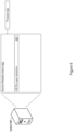
- Figure 1 shows an example of a system 100 that supports AR-based ply layup on a composite part layup tool.
- the system 100 shown in Figure 1 includes a computing system 102 and an AR headset 104.
- the computing system 102 may include a single or multiple computing devices such as application servers, compute nodes, desktop or laptop computers, smart phones or other mobile devices, tablet devices, embedded controllers, and more.
- the AR headset 104 may take the form of any wearable device that provides AR capabilities to digitally overlay computer-generated images upon a user's view of physical elements. As such, the AR headset 104 may be implemented as AR glasses or other viable AR headwear
- the computing system 102 may access, generate, or provide ply placement data for visualization through the AR headset 104.
- the ply placement data may provide various digital enhancements to a physical view to assist, guide, or inform a user in ply layups using a composite part layup tool.
- the computing system 102 may provide CAD generated ply placement positions, incremental placement paths, simulated layups, ply interest zones, real-time feedback (after physical layup occurs), and other forms of ply placement data to the AR headset 104 for visualization.
- the AR headset 104 may overlay the ply placement data upon a physical view of a composite part layup tool or already-applied ply layers, even as a user changes physical positions during construction of a composite laminate.
- the computing system 102 shown in Figure 1 includes an AR ply layup engine 110.
- the computing system 100 may implement the AR ply layup engine 110 (and components thereof) in various ways, for example as hardware and programming.
- the programming for the AR ply layup engine 110 may take the form of processor-executable instructions stored on a non-transitory machine-readable storage medium and the hardware for the AR ply layup engine 110 may include a processor to execute those instructions.
- a processor may take the form of single processor or multiprocessor systems.
- the AR headset 104 may drive an AR view that digitally visualizes ply placement data on a composite part layup tool physically visible through the AR headset 104.
- the AR ply layup engine 110 may analyze a view of the AR headset 104 to identify the composite part layup tool, match a CAD generated ply placement position of a given ply to layup via the composite part layup tool, and provide the CAD generated ply placement position of the given ply to the AR headset as the ply placement data to digitally overlay on the composite part layup tool physically visible through the AR headset 104.
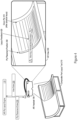
- Figure 2 shows an example of ply placement data that an AR ply layup engine may provide to an AR headset to digitally overlay on a view of a composite part layup tool.
- Figure 2 illustrates a composite part layup tool 210 visible via the AR headset 104 (the user/operator is not shown).
- the AR headset 104 may be communicatively linked to the AR ply layup engine 110, e.g., via one or more networks any type or protocol (e.g., wireless technologies such as Bluetooth, 3G, 4G, 5G, 802.11, etc.).
- the AR headset 104 itself may implement some (or all) of the various features of the AR ply layup engine 110 as described herein.
- the AR headset 104 may transmit a current view of physical elements visible through the AR headset 104.
- the AR headset 104 provides view data 220 to the AR ply layup engine 110, which may include any image or video data that represents a view visible through the AR headset 104.
- the AR headset 104 may include a digital image capture device (e.g., a digital camera) by which the view data 220 is obtained and then transmitted to the AR ply layup engine 110.
- the view data 220 may include digital video data, static images, or combinations thereof.
- the AR ply layup engine 110 may analyze the view data 220 to identify the composite part layup tool 210 or already-placed plies. To do so, the AR ply layup engine 110 may parse through the view data 220 to identify any discernable characteristics, properties, elements, points, or other identifying data for the composite part layup tool 210 or previously placed plies during construction of a composite laminate. Identifying characteristics for the composite part layup tool 210 may include any physical identification points physically embedded, include, or constructed on the composite part layup tool 210 itself (e.g., specifically to support AR-based ply layups and detection in an AR view).
- the AR ply layup engine 110 may identify characteristics of already-placed plies, e.g., via comparison to CAD simulations to compare fiber characteristics or orientations, composite material (e.g., ply) characteristics, and the like. For a composite laminate that is partially constructed (e.g., with one or more ply layups already completed on the composite part layup tool 210), the AR ply layup engine 110 may analyze the view data 220 to determine a present state of a ply layup process.
- the AR ply layup engine 110 may identify specific textures or ply materials present in the view data 220, along with relevant positions and layering of such plies, in order to determine which plies have been placed using the composite part layup tool 210. Such data may be relevant to determine a subsequent ply to layup via the compositely layup tool 210 to form a composite laminate. Additionally or alternatively, the AR ply layup engine 110 may track a present state of the ply layup process as successive plies are placed and laminated, e.g., as tracked via the view data 220 or other user indication.
- the AR ply layup engine 110 may also determine an orientation of the AR headset 104 (and accordingly a user) as positioned with respect to the composite part layup tool 210 and already-placed plies. Doing so may allow the AR ply layup engine 110 to more precisely, accurately, or efficiently provide ply placement data to augment the physical view of the composite part layup tool 210.
- the AR-based ply layup features described herein may provide a user with the flexibility to physically move during a ply layup process.
- a user may be free to move around the composite part layup tool 210 to, for example, find a better layup angle to place a given ply or to find a better position to layup the given ply along various boundaries.
- the AR ply layup engine 110 may continually analyze the view data 220 to properly identify positioning of ply placement data provided to the AR headset 104 to digitally overlay.
- the AR ply layup engine 110 may provide various forms of ply placement data to the AR headset 104 to support AR-based ply layups.
- the AR ply layup engine 110 transmits the ply placement data 230 to the AR headset 104, by which the AR headset 104 may augment the physical view visible through the AR headset 104.
- the AR ply layup engine 110 may obtain and provide ply placement data 230 on a per-ply basis. Since ply layups occur sequentially during composite laminate construction, the AR ply layup engine 110 may generate and provide ply placement data 230 for a current ply to be, is being, or has been laid up via the composite part layup tool 210.
- the ply placement data 230 is CAD generated, for example via a fiber simulation CAD tool or other CAD tool with CAD design, simulation, and testing capabilities for composite laminates constructed through a series of ply layups.
- the AR ply layup engine 110 may obtain and provide ply placement positions for plies placed via the composite part layup tool 210. Such ply placement positions may provide an indication of the specific locations at which plies are to be laid up on the composite part layup tool 210, visible as digital overlays on the actual surface of the composite part layup tool 210 through the AR headset 104.
- the ply placement data 230 provided by the AR ply layup engine 110 may specify the specific positions (e.g., locations in the view of the AR headset 104) at which to digitally augment with the ply placement data 230.
- Figure 2 depicts an example composite interface (e.g., composite view) visible through the AR headset 104 as the AR view 240.
- the AR headset 104 may drive the AR view 240 by augmenting the physical view of the composite part layup tool 210 with the ply placement data 230 received from the AR ply layup engine 110.
- the AR headset 104 overlays a ply placement position 250 over the physical view of the composite part layup tool 210.
- the ply placement position 250 may provide any type of positioning data applicable to a given ply for construction of a composite laminate using the composite part layup tool 210.
- the ply placement position 250 is shown as a dotted outline digitally overlaid on the view of the AR headset 104, and specifically positioned over the relevant portions of the surface of the composite part layup tool 210 (or, in other cases, previously laid plies) in which a given ply is to be placed.
- the AR ply layup engine 110 may continually update the positioning for the ply placement position 250 within the view of the AR headset 104 such that the ply placement position 250 is accurately overlaid across the physical surface of the composite part layup tool 210.
- the AR headset 104 (via the AR ply layup engine 110) may visualize 3D ply outlines on a surface of the composite part layup tool 210, assisting a user in the actual manual layup of a given ply even as the user moves and the field of vision through the AR headset 104 changes.
- Figure 2 provides an example of ply placement data 230 in the form of ply placement position 250
- the AR ply layup engine 110 and AR headset 104 may support various other forms of ply placement data 230 as well, some of which are presented next in Figure 3 .
- Figure 3 shows further examples of ply placement data that the AR ply layup engine 110 may provide to the AR headset 104 to digitally overlay on a view of a composite part layup tool 210.
- the AR headset 104 drives an AR view 240 to digitally augment the ply placement data 230 provided by the AR ply layup engine 110.
- the ply placement data 230 shown in Figure 3 includes the ply placement position 250 (e.g., as described for Figure 2 ), a ply interest zone 360, and an incremental placement path 370 for a given ply. These forms of ply placement data 230 are depicted in the AR view 240 shown in Figure 3 .
- the AR ply layup engine 110 may identify selected portions of a given ply that exhibit different layup characteristics than other portions of the given ply. For instance, a ply portion may require a specific 3D shape, pressure requirement, texture, or other layup application characteristic that impacts the effectiveness in performing a layup for the given ply. Such characteristics may result in wrinkling during layup or cause other unwanted results, e.g., may be identified or predicted via CAD simulation.
- the AR ply layup engine 110 may identify relevant interest zones for a given ply from such CAD simulation data (e.g., access from a CAD tool used to model and simulate construction of a composite laminate including a given ply), which the AR ply layup engine 110 may include in the ply placement data 230 as ply interest zones.
- CAD simulation data e.g., access from a CAD tool used to model and simulate construction of a composite laminate including a given ply
- example ply interest zones include portions susceptible to wrinkling or distortion during layup.
- the ply interest zone 360 depicted in the AR view 240 of Figure 3 shows one example of how the AR ply layup engine 110 may identify a ply region and how the AR headset 104 may augment a view to highlight an identified ply region.
- the ply interest zone 360 may indicate a (relative) high probability or wrinkling or indicate to a user that the highlighted ply portion may require increased lamination pressure, and the like.
- Such zones may be color-coded based on a degree of susceptibility to undesired effects, e.g., using a green, yellow, and red color scale indicative of wrinkling degree.
- the AR ply layup engine 110 includes an incremental placement path for a given ply as part of the ply placement data 230.
- the incremental data path specifies a sequence to layup a particular ply, which guides a user in ply layups with increased efficiency or effectiveness.
- the AR ply layup engine 110 obtains an incremental placement path from a CAD tool that has analyzed the particular ply, composite part layup tool 210, or other factors to determine a sequence of ply application.
- the AR ply layup engine 110 provides an incremental placement path 370 for a given ply as part of the ply placement data 230.
- the AR headset 104 projects the incremental placement path 370 over the surface of the composite part layup tool 210 (or possibly the given ply itself during actual layup of the given ply by a user).
- the example incremental placement path 370 shown in Figure 3 is in the form of numbered arrows which may signal a sequence for a user to layup various portions of a given ply. Any other visual sequence indicators can be generated by the AR ply layup engine 110 and overlaid by the AR headset 104.
- the AR ply layup engine 110 dynamically updates the incremental placement path 370 as actual layup of a given ply occurs.
- the AR headset 104 continuously transmits view data 220 of the given ply during physical layup, which the AR ply layup engine 110 analyzes to determine a current state of the physical layup for a given ply.
- the AR ply layup engine 110 updates the incremental placement path 370 to account for completed portions of a present ply layup.
- the AR headset 104 removes the completed portions of the incremental placement path 370 as the physical layup portions of the given ply are completed.
- Ply placement positions, ply interest zones, and incremental placement paths are but three (3) examples of ply placement data that the AR ply layup engine 110 may access (e.g., generate or obtain) and the AR headset 104 may overlay in an AR view 240.
- the AR ply layup engine 110 may access a layup simulation of applying a given ply on the composite part layup tool 210.
- the layup simulation may, for example, identify surface complexities that impact an effectiveness of the ply layup for the given ply (e.g., at ply interest zones along a surface of the given ply or composite part layup tool 210).
- the layup simulation may be, for example, produced by a CAD tool, from which the AR ply layup engine 110 may access the layup simulation.
- the AR ply layup engine 110 may include layup simulation data as part of the ply placement data 230.
- the AR headset 104 may overlay the layup simulation over the actual surface of the composite part layup tool 210, which may provide a user a digital and simulated view of how a given ply layup can occur over the surface of the composite part layup tool 210 (or other plies already applied unto a composite laminate).
- the AR headset 104 may drive the AR view 240 to overlay the layup simulation over an applicable portion of the composite part layup tool 210 physically visible through AR headset 104.
- the AR ply layup engine 110 may provide various forms of analysis data for the AR headset 104 to overlay in the AR view 240.
- Example analyses include structural analysis data that my indicate areas of stress or computational fluid dynamics (CFD) data, and the like.
- CFD computational fluid dynamics
- Such analysis data may, for example, by useful for a user to visualize in real-time during ply layup or with respect to an overlaid layup simulation. This may be particularly relevant as the AR headset 104 may project the analysis data specifically relevant to (e.g., overlaid upon) physical components actually visible through the AR headset 104 (e.g., the physical surfaces of the composite part layup tool 210 or other already-placed plies).
- Figure 4 shows an example of real-time analysis that the AR ply layup engine 110 and AR headset 104 may provide after physical layup of a given ply.
- a given ply 410 is visible through the AR headset 104 after physical layup of the given ply, e.g., as shown through the AR view 240.
- View data 220 of the given ply 410 may be transmitted to the AR ply layup engine 110 by the AR headset 104, from which the AR ply layup engine 110 may respond with analysis data.
- the AR headset 104 captures a still image that includes the given ply 410 after physical layup for the AR ply layup engine 110 to analyze.
- the AR ply layup engine 110 may generate, as analysis data, feedback for the physical layup of the given ply 410. Analysis performed or obtained by the AR ply layup engine 110 may include layup boundary or edge positioning comparisons between the actual physical layup of the given ply 410 and CAD generated simulations or ply placement positions. As another example analysis, the AR ply layup engine 110 may analyze fiber textures, orientations, or paths of the given ply after physical layup to determine layup efficacy (e.g., via comparison to CAD simulated ply layups for the given ply 410). Such analysis may include whether the physical fiber orientations are within an acceptable tolerance from a target orientation requirement (e.g., as determined via simulation, as set by CAD tools, or with respect a user-specified goal).
- a target orientation requirement e.g., as determined via simulation, as set by CAD tools, or with respect a user-specified goal.
- the AR ply layup engine 110 analyzes a captured image of the given ply 410 after physical layup to provide layup feedback 420.
- the AR ply layup engine 110 may include the layup feedback 420 as part of the ply placement data 230, which the AR headset 104 may overlay into the AR view 240.
- the layup feedback 420 may take the form of a warning message, e.g., that indicates an edge (or multiple edges) of the given ply 410 after layup are at least a threshold distance from the ply placement position 250 specified for the given ply 410.
- Similar forms of layup feedback may be provided by the AR ply layup engine 110 for disoriented fibers or other determined issues.
- the AR ply layup engine 110 and AR headset 104 may support foreign object detection for ply layups. For example, after physical layup of a given ply, the AR ply layup engine 110 may parse view data 220 provided by the AR headset 104 to analyze whether any unexpected objects are located on the composite part layup tool 210 or plies placed for the composite laminate. Such foreign object detection analysis may, for example, include comparing simulation data or expected material or laminate textures to identify inconsistencies. Example foreign objects may include any dropped items or debris inadvertently placed on the composite laminate, which the AR ply layup engine 110 may detect through such analysis.
- the AR headset 104 provides a convenient mechanism to scan portions of the composite laminate (e.g., including crevices or portions blocked at different lines of sight), the AR ply layup engine 110 may detect foreign objects that may otherwise be missed by static camera systems or user error.
- the AR ply layup engine 110 and AR headset 104 may support generation of quality reports for ply layups.
- the AR ply layup engine 110 may parse view data 220 provided by the AR headset 104 to capture relevant analysis data to include in a quality report.
- analysis data may include any combination of the various analyses discussed herein, such as ply edge verifications, foreign object detections, captured images of specific ply layups, inconsistency detections, or more.
- the AR ply layup engine 110 may aggregate relevant analysis data during ply layup and, in some implementations, automatically compile the quality report upon completion of the composite material.
- Figure 4 provides examples of real-time analysis provided by the AR ply layup engine 110 and AR headset 104 after physical layup of a given ply
- any of the analysis features may be provided, in a consistent manner, before or during physical layup of the given ply as well.
- the AR ply layup engine 110 and AR headset 104 may support provision of ply layup analysis data in real-time.
- the AR ply layup engine 110 may continually analyze view data 220 or captured images provided by the AR headset 104 to obtain and provide any of the various forms of analysis data described herein as ply placement data 230.
- the AR ply layup engine 110 may offer continuous or real-time feedback to a user as the physical layup for the given ply 410 occurs or completes, especially as a user views the physical surface of the given ply 410 upon application.
- the AR-based ply layup features described herein may increase the efficiency and effectiveness of ply layups.
- the AR ply layup engine 110 and AR headset 104 may provide and visualize ply placement data 230 in an AR view 240 to support AR-based ply layups.
- many composite part layup tools have complex structures and facades specific to the manufacture of particularized composite parts or plies.
- Such composite part layup tools may include deep crevices or block portions out of various lines of sight when viewing the composite layup engine. Such regions may be inaccessible by laser-guided or static camera systems.
- AR-based ply layups a user may view such inaccessible regions by adjusting their physical position, all the while the AR headset 104 may overlay applicable ply placement data for such regions provided by the AR ply layup engine 110.
- Figure 5 shows an example of logic 500 that a system may implement to support AR-based ply layups on a composite part layup tool.
- the computing system 102 implements the logic 500 as hardware, executable instructions stored on a machine-readable medium, or as a combination of both.
- the computing system 102 may implement the logic 500 as the AR ply layup engine 110, through which the computing system 102 may perform or execute the logic 500 as a method for generate and provide ply placement data to an AR headset for AR-based ply layups.
- the following description of the logic 500 is provided using the AR ply layup engine 110 as an example. However, various other implementation options by the computing system 100 are possible.
- the AR ply layup engine 110 may analyze a view of an AR headset to identify a composite part layup tool visible through an AR headset (502) and match a CAD generated ply placement position of a given ply to layup via the composite part layup tool (504).
- the ply placement position may form part of the ply placement data that the AR ply layup engine 110 may obtain and provide to the AR headset.
- the AR ply layup engine 110 may provide the CAD generated ply placement position of the given ply to the AR headset as ply placement data to digitally overlay on the composite part layup tool visible through the AR headset (506).
- FIG. 6 shows an example of a system 600 that supports AR-based ply layups on a composite part layup tool.
- the system 600 may include a processor 610, which may take the form of a single or multiple processors.
- the processor(s) 610 may include a central processing unit (CPU), microprocessor, or any hardware device suitable for executing instructions stored on a machine-readable medium.
- the system 600 may include a machine-readable medium 620.
- the machine-readable medium 620 may take the form of any non-transitory electronic, magnetic, optical, or other physical storage device that stores executable instructions, such as the AR ply layup instructions 622 shown in Figure 6 .
- the machine-readable medium 620 may be, for example, Random Access Memory (RAM) such as a dynamic RAM (DRAM), flash memory, spin-transfer torque memory, an Electrically-Erasable Programmable Read-Only Memory (EEPROM), a storage drive, an optical disk, and the like.
- RAM Random Access Memory
- DRAM dynamic RAM
- EEPROM Electrically-Erasable Programmable Read-Only Memory
- storage drive an optical disk, and the like.
- the system 600 may execute instructions stored on the machine-readable medium 620 through the processor 610. Executing the instructions may cause the system 600 (or any other CAD system) to perform any of the AR-based ply layup features described herein, including according to any of the features with respect to the AR ply layup engine 110, the AR headset 104, or combinations thereof.
- execution of the AR ply layup instructions 622 by the processor 610 may cause the system 600 to analyze a view of an AR headset to identify a composite part layup tool visible through an AR headset; match a CAD generated ply placement position of a given ply to layup via the composite part layup tool; determine an incremental placement path for the given ply; and provide the CAD generated ply placement position and the incremental placement path for the given ply to the AR headset as ply placement data to digitally overlay on the composite part layup tool visible through the AR headset.
- Execution of the ply layup instructions 622 may cause the system 600 to perform any number additional or alternative features as described herein, by which the system 600 may support AR-based ply layups on a composite part layup tool.
- the systems, methods, devices, and logic described above, including the AR ply layup engine 110 and AR headset 104, may be implemented in many different ways in many different combinations of hardware, logic, circuitry, and executable instructions stored on a machine-readable medium.
- the AR ply layup engine 110 or the AR headset 104 may include circuitry in a controller, a microprocessor, or an application specific integrated circuit (ASIC), or may be implemented with discrete logic or components, or a combination of other types of analog or digital circuitry, combined on a single integrated circuit or distributed among multiple integrated circuits.
- ASIC application specific integrated circuit
- a product such as a computer program product, may include a storage medium and machine readable instructions stored on the medium, which when executed in an endpoint, computer system, or other device, cause the device to perform operations according to any of the description above, including according to any features of the AR ply layup engineH 10, the AR headset 104, or combinations thereof.
- the processing capability of the systems, devices, and engines described herein, including the AR ply layup engine 110, may be distributed among multiple system components, such as among multiple processors and memories, optionally including multiple distributed processing systems or cloud/network elements.
- Parameters, databases, and other data structures may be separately stored and managed, may be incorporated into a single memory or database, may be logically and physically organized in many different ways, and may implemented in many ways, including data structures such as linked lists, hash tables, or implicit storage mechanisms.
- Programs may be parts (e.g., subroutines) of a single program, separate programs, distributed across several memories and processors, or implemented in many different ways, such as in a library (e.g., a shared library).
Landscapes
- Engineering & Computer Science (AREA)
- Physics & Mathematics (AREA)
- General Physics & Mathematics (AREA)
- Theoretical Computer Science (AREA)
- General Engineering & Computer Science (AREA)
- Computer Hardware Design (AREA)
- Geometry (AREA)
- Software Systems (AREA)
- Computer Graphics (AREA)
- Optics & Photonics (AREA)
- Evolutionary Computation (AREA)
- Computer Vision & Pattern Recognition (AREA)
- Architecture (AREA)
- Computational Mathematics (AREA)
- Mathematical Analysis (AREA)
- Mathematical Optimization (AREA)
- Pure & Applied Mathematics (AREA)
- Moulding By Coating Moulds (AREA)
- Road Repair (AREA)
Description
- Composite part layup tools may be used to perform ply layups for construction of a composite part. Systems exist to guide a layup operator in laying up plies of composite materials on layup tooling to construct the composite part.
WO 2017/009128 A1 describes a headset configured to augment a wearer of the headset's view of fabric shapes when transferring the fabric shapes from a plurality of stacks of fabric shapes to a plurality of moulds, the headset comprising a processor and an optical device configured to overlay graphics in the wearer's field of view according to instructions from the processor. The processor is configured to instruct the optical device to highlight a next one of the fabric shapes to be picked up from the stacks of fabric shapes, and to highlight one of the moulds to which the next fabric shape should be added, in response to a notification that a previous fabric shape has been placed into a previously highlighted one of the moulds.
Matthew Such et al: "Intelligent Composite Layup by the Application of Low Cost Tracking and Projection Technologies", PROCEDIA CIRP, vol. 25, 10 December 2014, pages 122-131, DOI: 10.1016/j.procir.2014.10.020, discloses a system the guides a user the a ply layup process with instructions that are projected onto the composite part on which the ply is to be formed. - Disclosed implementations include systems, methods, devices, and logic that support ply layups on a composite part layup tool using augmented reality (AR). Augmented reality may refer to any technology or mechanism to superimpose (e.g., overlay) computer-generated images on a view of a physical elements, and various features for AR-based ply layups are described herein.
The invention is defined by the independent claims. - Certain examples are described in the following detailed description and in reference to the drawings.
-
Figure 1 shows an example of a system that supports AR-based ply layups on a composite part layup tool. -
Figure 2 shows an example of ply placement data that an AR ply layup engine may provide to an AR headset to digitally overlay on a view of a composite part layup tool. -
Figure 3 shows further examples of ply placement data that the AR ply layup engine may provide to the AR headset to digitally overlay on a view of a composite part layup tool. -
Figure 4 shows an example of real-time analysis that the AR ply layup engine and AR headset may provide after physical layup of a given ply. -
Figure 5 shows an example of logic that a system may implement to support AR-based ply layups on a composite part layup tool. -
Figure 6 shows an example of a system that supports AR-based ply layups on a composite part layup tool. - The discussion below refers to plies and composite part layup tools, which may be used to construct, manufacture, or otherwise form a composite part. Composite parts (also referred to herein as composite laminates) may refer to any object or structure that is composed of multiple layers of material (e.g., plies). Composite parts may be formed by sequentially layering ply by ply to construct the composite part or composite laminate, many times through use of a composite part layup tool. Construction of composite parts is used in many industries, for instance in aerospace, automotive, transport, textile, and various other industries. Physical layup of a ply (e.g., via placement, lamination, or attachment) may be performed on the surface of a composite part layup tool. Composite part layup tools may provide a specifically-shaped physical surface upon which layers of plies are successively placed to form the composite laminate. Composite laminates continue to increase in complexity, sometimes requiring tens, hundreds, or thousands of ply layups to construct the end product. Ply layups may thus require a high degree of precision, are many times unique to a specific product, and often require time-intensive manual labor.
- Various tools exist to guide an operator in manually placing plies across a composite part layup tool to form a composite laminate. Some guiding systems may utilize lasers to trace an outline of plies for layup on a composite part layup tool, but these laser systems can be expensive, rigid, and difficult to program. Static cameras may be used to view a composite part layup tool and added plies, but such systems are also inflexible and difficult to maneuver, often times limiting the degree to which an operator can fully view the composite part layup tool and properly layup successive plies at different positions over a composite part layup tool.
- The disclosure herein may provide systems, methods, devices, and logic for AR-based ply layups. As described in greater detail herein, AR-based ply layups may provide mechanisms for flexible and accurate CAD generated ply placement data that is overlaid, via AR technologies, over a composite part layup tool. Various forms of ply placement data may be generated and visualized via AR devices, which may provide digital enhancements that are overlaid on a view of the composite part layup tool itself and any ply layers already applied for construction of a composite laminate. Examples of ply placement data contemplated herein include ply outlines, incremental placement paths, draping simulation results, potential distortion and defects, layup instructions or real-time feedback, each of which may be digitally overlaid to assist a user in ply layups. Moreover, the AR-based ply layup features described herein may consistently supply such AR-based visual enhancements while maintaining a user's freedom to physically move and layup plies via the composite part layup tool, which may be not be possible with other position-fixed ply layup tools.
-
Figure 1 shows an example of asystem 100 that supports AR-based ply layup on a composite part layup tool. Thesystem 100 shown inFigure 1 includes acomputing system 102 and anAR headset 104. Thecomputing system 102 may include a single or multiple computing devices such as application servers, compute nodes, desktop or laptop computers, smart phones or other mobile devices, tablet devices, embedded controllers, and more. TheAR headset 104 may take the form of any wearable device that provides AR capabilities to digitally overlay computer-generated images upon a user's view of physical elements. As such, theAR headset 104 may be implemented as AR glasses or other viable AR headwear - As described in greater detail herein, the
computing system 102 may access, generate, or provide ply placement data for visualization through theAR headset 104. The ply placement data may provide various digital enhancements to a physical view to assist, guide, or inform a user in ply layups using a composite part layup tool. As such, thecomputing system 102 may provide CAD generated ply placement positions, incremental placement paths, simulated layups, ply interest zones, real-time feedback (after physical layup occurs), and other forms of ply placement data to theAR headset 104 for visualization. TheAR headset 104 may overlay the ply placement data upon a physical view of a composite part layup tool or already-applied ply layers, even as a user changes physical positions during construction of a composite laminate. - As an example implementation, the
computing system 102 shown inFigure 1 includes an ARply layup engine 110. Thecomputing system 100 may implement the AR ply layup engine 110 (and components thereof) in various ways, for example as hardware and programming. The programming for the ARply layup engine 110 may take the form of processor-executable instructions stored on a non-transitory machine-readable storage medium and the hardware for the ARply layup engine 110 may include a processor to execute those instructions. A processor may take the form of single processor or multiprocessor systems. - In operation, the
AR headset 104 may drive an AR view that digitally visualizes ply placement data on a composite part layup tool physically visible through theAR headset 104. In operation, the ARply layup engine 110 may analyze a view of theAR headset 104 to identify the composite part layup tool, match a CAD generated ply placement position of a given ply to layup via the composite part layup tool, and provide the CAD generated ply placement position of the given ply to the AR headset as the ply placement data to digitally overlay on the composite part layup tool physically visible through theAR headset 104. - These and other example features of AR-based ply layups according to the present disclosure are described in greater detail next.
-
Figure 2 shows an example of ply placement data that an AR ply layup engine may provide to an AR headset to digitally overlay on a view of a composite part layup tool. In particular,Figure 2 illustrates a compositepart layup tool 210 visible via the AR headset 104 (the user/operator is not shown). TheAR headset 104 may be communicatively linked to the ARply layup engine 110, e.g., via one or more networks any type or protocol (e.g., wireless technologies such as Bluetooth, 3G, 4G, 5G, 802.11, etc.). Although illustrated separately inFigure 2 , in some examples theAR headset 104 itself may implement some (or all) of the various features of the ARply layup engine 110 as described herein. - To support AR-based ply layups, the
AR headset 104 may transmit a current view of physical elements visible through theAR headset 104. InFigure 2 , theAR headset 104 providesview data 220 to the ARply layup engine 110, which may include any image or video data that represents a view visible through theAR headset 104. For instance, theAR headset 104 may include a digital image capture device (e.g., a digital camera) by which theview data 220 is obtained and then transmitted to the ARply layup engine 110. Theview data 220 may include digital video data, static images, or combinations thereof. - The AR
ply layup engine 110 may analyze theview data 220 to identify the compositepart layup tool 210 or already-placed plies. To do so, the ARply layup engine 110 may parse through theview data 220 to identify any discernable characteristics, properties, elements, points, or other identifying data for the compositepart layup tool 210 or previously placed plies during construction of a composite laminate. Identifying characteristics for the compositepart layup tool 210 may include any physical identification points physically embedded, include, or constructed on the compositepart layup tool 210 itself (e.g., specifically to support AR-based ply layups and detection in an AR view). - In a consistent manner, the AR
ply layup engine 110 may identify characteristics of already-placed plies, e.g., via comparison to CAD simulations to compare fiber characteristics or orientations, composite material (e.g., ply) characteristics, and the like. For a composite laminate that is partially constructed (e.g., with one or more ply layups already completed on the composite part layup tool 210), the ARply layup engine 110 may analyze theview data 220 to determine a present state of a ply layup process. For instance, the ARply layup engine 110 may identify specific textures or ply materials present in theview data 220, along with relevant positions and layering of such plies, in order to determine which plies have been placed using the compositepart layup tool 210. Such data may be relevant to determine a subsequent ply to layup via thecompositely layup tool 210 to form a composite laminate. Additionally or alternatively, the ARply layup engine 110 may track a present state of the ply layup process as successive plies are placed and laminated, e.g., as tracked via theview data 220 or other user indication. - By analyzing the
view data 220, the ARply layup engine 110 may also determine an orientation of the AR headset 104 (and accordingly a user) as positioned with respect to the compositepart layup tool 210 and already-placed plies. Doing so may allow the ARply layup engine 110 to more precisely, accurately, or efficiently provide ply placement data to augment the physical view of the compositepart layup tool 210. - The AR-based ply layup features described herein may provide a user with the flexibility to physically move during a ply layup process. As the
AR headset 104 may be physically worn, a user may be free to move around the compositepart layup tool 210 to, for example, find a better layup angle to place a given ply or to find a better position to layup the given ply along various boundaries. As the user moves, the ARply layup engine 110 may continually analyze theview data 220 to properly identify positioning of ply placement data provided to theAR headset 104 to digitally overlay. - Turning to the ply placement data itself, the AR
ply layup engine 110 may provide various forms of ply placement data to theAR headset 104 to support AR-based ply layups. InFigure 2 , the ARply layup engine 110 transmits theply placement data 230 to theAR headset 104, by which theAR headset 104 may augment the physical view visible through theAR headset 104. The ARply layup engine 110 may obtain and provideply placement data 230 on a per-ply basis. Since ply layups occur sequentially during composite laminate construction, the ARply layup engine 110 may generate and provideply placement data 230 for a current ply to be, is being, or has been laid up via the compositepart layup tool 210. In some implementations, theply placement data 230 is CAD generated, for example via a fiber simulation CAD tool or other CAD tool with CAD design, simulation, and testing capabilities for composite laminates constructed through a series of ply layups. - As a particular example, the AR
ply layup engine 110 may obtain and provide ply placement positions for plies placed via the compositepart layup tool 210. Such ply placement positions may provide an indication of the specific locations at which plies are to be laid up on the compositepart layup tool 210, visible as digital overlays on the actual surface of the compositepart layup tool 210 through theAR headset 104. In that regard, theply placement data 230 provided by the ARply layup engine 110 may specify the specific positions (e.g., locations in the view of the AR headset 104) at which to digitally augment with theply placement data 230. - To provide an illustration of visualization of the
ply placement data 230,Figure 2 depicts an example composite interface (e.g., composite view) visible through theAR headset 104 as theAR view 240. TheAR headset 104 may drive theAR view 240 by augmenting the physical view of the compositepart layup tool 210 with theply placement data 230 received from the ARply layup engine 110. In theAR view 240 depicted inFigure 2 , theAR headset 104 overlays aply placement position 250 over the physical view of the compositepart layup tool 210. Theply placement position 250 may provide any type of positioning data applicable to a given ply for construction of a composite laminate using the compositepart layup tool 210. - In
Figure 2 , theply placement position 250 is shown as a dotted outline digitally overlaid on the view of theAR headset 104, and specifically positioned over the relevant portions of the surface of the composite part layup tool 210 (or, in other cases, previously laid plies) in which a given ply is to be placed. As a user moves, the ARply layup engine 110 may continually update the positioning for theply placement position 250 within the view of theAR headset 104 such that theply placement position 250 is accurately overlaid across the physical surface of the compositepart layup tool 210. Thus, the AR headset 104 (via the AR ply layup engine 110) may visualize 3D ply outlines on a surface of the compositepart layup tool 210, assisting a user in the actual manual layup of a given ply even as the user moves and the field of vision through theAR headset 104 changes. - While
Figure 2 provides an example ofply placement data 230 in the form ofply placement position 250, the ARply layup engine 110 andAR headset 104 may support various other forms ofply placement data 230 as well, some of which are presented next inFigure 3 . -
Figure 3 shows further examples of ply placement data that the ARply layup engine 110 may provide to theAR headset 104 to digitally overlay on a view of a compositepart layup tool 210. InFigure 3 , theAR headset 104 drives anAR view 240 to digitally augment theply placement data 230 provided by the ARply layup engine 110. Theply placement data 230 shown inFigure 3 includes the ply placement position 250 (e.g., as described forFigure 2 ), aply interest zone 360, and anincremental placement path 370 for a given ply. These forms ofply placement data 230 are depicted in theAR view 240 shown inFigure 3 . - For the
ply interest zone 360, the ARply layup engine 110 may identify selected portions of a given ply that exhibit different layup characteristics than other portions of the given ply. For instance, a ply portion may require a specific 3D shape, pressure requirement, texture, or other layup application characteristic that impacts the effectiveness in performing a layup for the given ply. Such characteristics may result in wrinkling during layup or cause other unwanted results, e.g., may be identified or predicted via CAD simulation. The ARply layup engine 110 may identify relevant interest zones for a given ply from such CAD simulation data (e.g., access from a CAD tool used to model and simulate construction of a composite laminate including a given ply), which the ARply layup engine 110 may include in theply placement data 230 as ply interest zones. Thus, example ply interest zones include portions susceptible to wrinkling or distortion during layup. - The
ply interest zone 360 depicted in theAR view 240 ofFigure 3 shows one example of how the ARply layup engine 110 may identify a ply region and how theAR headset 104 may augment a view to highlight an identified ply region. Theply interest zone 360 may indicate a (relative) high probability or wrinkling or indicate to a user that the highlighted ply portion may require increased lamination pressure, and the like. Such zones may be color-coded based on a degree of susceptibility to undesired effects, e.g., using a green, yellow, and red color scale indicative of wrinkling degree. - The AR
ply layup engine 110 includes an incremental placement path for a given ply as part of theply placement data 230. The incremental data path specifies a sequence to layup a particular ply, which guides a user in ply layups with increased efficiency or effectiveness. In some examples, the ARply layup engine 110 obtains an incremental placement path from a CAD tool that has analyzed the particular ply, compositepart layup tool 210, or other factors to determine a sequence of ply application. - In
Figure 3 , the ARply layup engine 110 provides anincremental placement path 370 for a given ply as part of theply placement data 230. As seen inFigure 3 , theAR headset 104 projects theincremental placement path 370 over the surface of the composite part layup tool 210 (or possibly the given ply itself during actual layup of the given ply by a user). The exampleincremental placement path 370 shown inFigure 3 is in the form of numbered arrows which may signal a sequence for a user to layup various portions of a given ply. Any other visual sequence indicators can be generated by the ARply layup engine 110 and overlaid by theAR headset 104. - In some implementations, the AR
ply layup engine 110 dynamically updates theincremental placement path 370 as actual layup of a given ply occurs. In that regard, theAR headset 104 continuously transmitsview data 220 of the given ply during physical layup, which the ARply layup engine 110 analyzes to determine a current state of the physical layup for a given ply. As a user layups specific portions of the given ply (e.g., completes step 1 of the incremental placement path 370), the ARply layup engine 110 updates theincremental placement path 370 to account for completed portions of a present ply layup. TheAR headset 104, in effect, removes the completed portions of theincremental placement path 370 as the physical layup portions of the given ply are completed. - Ply placement positions, ply interest zones, and incremental placement paths are but three (3) examples of ply placement data that the AR
ply layup engine 110 may access (e.g., generate or obtain) and theAR headset 104 may overlay in anAR view 240. - As yet another example, the AR
ply layup engine 110 may access a layup simulation of applying a given ply on the compositepart layup tool 210. The layup simulation may, for example, identify surface complexities that impact an effectiveness of the ply layup for the given ply (e.g., at ply interest zones along a surface of the given ply or composite part layup tool 210). The layup simulation may be, for example, produced by a CAD tool, from which the ARply layup engine 110 may access the layup simulation. - To overlay the layup simulation in the
AR view 240, the ARply layup engine 110 may include layup simulation data as part of theply placement data 230. In some implementations, theAR headset 104 may overlay the layup simulation over the actual surface of the compositepart layup tool 210, which may provide a user a digital and simulated view of how a given ply layup can occur over the surface of the composite part layup tool 210 (or other plies already applied unto a composite laminate). As such, theAR headset 104 may drive theAR view 240 to overlay the layup simulation over an applicable portion of the compositepart layup tool 210 physically visible throughAR headset 104. - As other examples of ply placement data, the AR
ply layup engine 110 may provide various forms of analysis data for theAR headset 104 to overlay in theAR view 240. Example analyses include structural analysis data that my indicate areas of stress or computational fluid dynamics (CFD) data, and the like. Such analysis data may, for example, by useful for a user to visualize in real-time during ply layup or with respect to an overlaid layup simulation. This may be particularly relevant as theAR headset 104 may project the analysis data specifically relevant to (e.g., overlaid upon) physical components actually visible through the AR headset 104 (e.g., the physical surfaces of the compositepart layup tool 210 or other already-placed plies). - Additional examples of real-time analysis data are described next with respect to
Figure 4 -
Figure 4 shows an example of real-time analysis that the ARply layup engine 110 andAR headset 104 may provide after physical layup of a given ply. InFigure 4 , a givenply 410 is visible through theAR headset 104 after physical layup of the given ply, e.g., as shown through theAR view 240.View data 220 of the givenply 410 may be transmitted to the ARply layup engine 110 by theAR headset 104, from which the ARply layup engine 110 may respond with analysis data. In other examples, theAR headset 104 captures a still image that includes the givenply 410 after physical layup for the ARply layup engine 110 to analyze. - The AR
ply layup engine 110 may generate, as analysis data, feedback for the physical layup of the givenply 410. Analysis performed or obtained by the ARply layup engine 110 may include layup boundary or edge positioning comparisons between the actual physical layup of the givenply 410 and CAD generated simulations or ply placement positions. As another example analysis, the ARply layup engine 110 may analyze fiber textures, orientations, or paths of the given ply after physical layup to determine layup efficacy (e.g., via comparison to CAD simulated ply layups for the given ply 410). Such analysis may include whether the physical fiber orientations are within an acceptable tolerance from a target orientation requirement (e.g., as determined via simulation, as set by CAD tools, or with respect a user-specified goal). - In the specific example shown in
Figure 4 , the ARply layup engine 110 analyzes a captured image of the givenply 410 after physical layup to providelayup feedback 420. The ARply layup engine 110 may include thelayup feedback 420 as part of theply placement data 230, which theAR headset 104 may overlay into theAR view 240. As seen inFigure 4 , thelayup feedback 420 may take the form of a warning message, e.g., that indicates an edge (or multiple edges) of the givenply 410 after layup are at least a threshold distance from theply placement position 250 specified for the givenply 410. Similar forms of layup feedback may be provided by the ARply layup engine 110 for disoriented fibers or other determined issues. - As another example of analysis features, the AR
ply layup engine 110 andAR headset 104 may support foreign object detection for ply layups. For example, after physical layup of a given ply, the ARply layup engine 110 may parseview data 220 provided by theAR headset 104 to analyze whether any unexpected objects are located on the compositepart layup tool 210 or plies placed for the composite laminate. Such foreign object detection analysis may, for example, include comparing simulation data or expected material or laminate textures to identify inconsistencies. Example foreign objects may include any dropped items or debris inadvertently placed on the composite laminate, which the ARply layup engine 110 may detect through such analysis. As theAR headset 104 provides a convenient mechanism to scan portions of the composite laminate (e.g., including crevices or portions blocked at different lines of sight), the ARply layup engine 110 may detect foreign objects that may otherwise be missed by static camera systems or user error. - As yet another example analysis feature, the AR
ply layup engine 110 andAR headset 104 may support generation of quality reports for ply layups. Before, during, or after physical layup of plies in construction of a composite laminate, the ARply layup engine 110 may parseview data 220 provided by theAR headset 104 to capture relevant analysis data to include in a quality report. Such analysis data may include any combination of the various analyses discussed herein, such as ply edge verifications, foreign object detections, captured images of specific ply layups, inconsistency detections, or more. The ARply layup engine 110 may aggregate relevant analysis data during ply layup and, in some implementations, automatically compile the quality report upon completion of the composite material. - While
Figure 4 provides examples of real-time analysis provided by the ARply layup engine 110 andAR headset 104 after physical layup of a given ply, any of the analysis features may be provided, in a consistent manner, before or during physical layup of the given ply as well. The ARply layup engine 110 andAR headset 104 may support provision of ply layup analysis data in real-time. In that regard, the ARply layup engine 110 may continually analyzeview data 220 or captured images provided by theAR headset 104 to obtain and provide any of the various forms of analysis data described herein asply placement data 230. In doing so, the ARply layup engine 110 may offer continuous or real-time feedback to a user as the physical layup for the givenply 410 occurs or completes, especially as a user views the physical surface of the givenply 410 upon application. As such, the AR-based ply layup features described herein may increase the efficiency and effectiveness of ply layups. - In any of the ways described herein, the AR
ply layup engine 110 andAR headset 104 may provide and visualizeply placement data 230 in anAR view 240 to support AR-based ply layups. As yet another potential benefit of AR-based ply layups, many composite part layup tools have complex structures and facades specific to the manufacture of particularized composite parts or plies. Such composite part layup tools may include deep crevices or block portions out of various lines of sight when viewing the composite layup engine. Such regions may be inaccessible by laser-guided or static camera systems. However, with AR-based ply layups, a user may view such inaccessible regions by adjusting their physical position, all the while theAR headset 104 may overlay applicable ply placement data for such regions provided by the ARply layup engine 110. -
Figure 5 shows an example oflogic 500 that a system may implement to support AR-based ply layups on a composite part layup tool. In some examples, thecomputing system 102 implements thelogic 500 as hardware, executable instructions stored on a machine-readable medium, or as a combination of both. Thecomputing system 102 may implement thelogic 500 as the ARply layup engine 110, through which thecomputing system 102 may perform or execute thelogic 500 as a method for generate and provide ply placement data to an AR headset for AR-based ply layups. The following description of thelogic 500 is provided using the ARply layup engine 110 as an example. However, various other implementation options by thecomputing system 100 are possible. - In implementing the
logic 500, the ARply layup engine 110 may analyze a view of an AR headset to identify a composite part layup tool visible through an AR headset (502) and match a CAD generated ply placement position of a given ply to layup via the composite part layup tool (504). The ply placement position may form part of the ply placement data that the ARply layup engine 110 may obtain and provide to the AR headset. As such, the ARply layup engine 110 may provide the CAD generated ply placement position of the given ply to the AR headset as ply placement data to digitally overlay on the composite part layup tool visible through the AR headset (506). -
Figure 6 shows an example of asystem 600 that supports AR-based ply layups on a composite part layup tool. Thesystem 600 may include aprocessor 610, which may take the form of a single or multiple processors. The processor(s) 610 may include a central processing unit (CPU), microprocessor, or any hardware device suitable for executing instructions stored on a machine-readable medium. Thesystem 600 may include a machine-readable medium 620. The machine-readable medium 620 may take the form of any non-transitory electronic, magnetic, optical, or other physical storage device that stores executable instructions, such as the ARply layup instructions 622 shown inFigure 6 . As such, the machine-readable medium 620 may be, for example, Random Access Memory (RAM) such as a dynamic RAM (DRAM), flash memory, spin-transfer torque memory, an Electrically-Erasable Programmable Read-Only Memory (EEPROM), a storage drive, an optical disk, and the like. - The
system 600 may execute instructions stored on the machine-readable medium 620 through theprocessor 610. Executing the instructions may cause the system 600 (or any other CAD system) to perform any of the AR-based ply layup features described herein, including according to any of the features with respect to the ARply layup engine 110, theAR headset 104, or combinations thereof. - For instance, execution of the AR
ply layup instructions 622 by theprocessor 610 may cause thesystem 600 to analyze a view of an AR headset to identify a composite part layup tool visible through an AR headset; match a CAD generated ply placement position of a given ply to layup via the composite part layup tool; determine an incremental placement path for the given ply; and provide the CAD generated ply placement position and the incremental placement path for the given ply to the AR headset as ply placement data to digitally overlay on the composite part layup tool visible through the AR headset. Execution of theply layup instructions 622 may cause thesystem 600 to perform any number additional or alternative features as described herein, by which thesystem 600 may support AR-based ply layups on a composite part layup tool. - The systems, methods, devices, and logic described above, including the AR
ply layup engine 110 andAR headset 104, may be implemented in many different ways in many different combinations of hardware, logic, circuitry, and executable instructions stored on a machine-readable medium. For example, the ARply layup engine 110 or theAR headset 104 may include circuitry in a controller, a microprocessor, or an application specific integrated circuit (ASIC), or may be implemented with discrete logic or components, or a combination of other types of analog or digital circuitry, combined on a single integrated circuit or distributed among multiple integrated circuits. A product, such as a computer program product, may include a storage medium and machine readable instructions stored on the medium, which when executed in an endpoint, computer system, or other device, cause the device to perform operations according to any of the description above, including according to any features of the AR ply layup engineH 10, theAR headset 104, or combinations thereof. - The processing capability of the systems, devices, and engines described herein, including the AR
ply layup engine 110, may be distributed among multiple system components, such as among multiple processors and memories, optionally including multiple distributed processing systems or cloud/network elements. Parameters, databases, and other data structures may be separately stored and managed, may be incorporated into a single memory or database, may be logically and physically organized in many different ways, and may implemented in many ways, including data structures such as linked lists, hash tables, or implicit storage mechanisms. Programs may be parts (e.g., subroutines) of a single program, separate programs, distributed across several memories and processors, or implemented in many different ways, such as in a library (e.g., a shared library). - While various examples have been described above, many more implementations are possible.
Claims (11)
- A system (100) comprising:an augmented reality (AR) headset (104) configured to drive an AR view (240) that digitally visualizes ply placement data (230) on a composite part layup tool (210) physically visible through the AR headset (104); andan AR ply layup engine (110) configured to:analyze a view of the AR headset (104) to identify the composite part layup tool (210);match a computer-aided design (CAD) generated ply placement position (250) of a given ply (410) to layup via the composite part layup tool (210); and provide the CAD generated ply placement position (250) of the given ply (410) to the AR headset (104) as the ply placement data (230) to digitally overlay on the composite part layup tool (210) physically visible through the AR headset (104);characterized in that the AR ply layup engine (110) is further configured to:determine an incremental placement path (370) for the given ply (410), wherein the incremental placement path (370) signals a sequence for a user to layup various portions of the given ply (410); andprovide the incremental placement path (370) for the given ply (410) to the AR headset (104) further as the ply placement data (230) to digitally overlay on the composite part layup tool (210) physically visible through the AR headset (104),wherein the AR headset (104) is further configured to continuously transmit view data (220) of the given ply (410) during physical layup, andthe AR ply layup engine (110) is further configured to continuously analyze the transmitted view data (220) to determine a current state of the physical layup for the given ply (410), and the AR headset (104) is configured to remove completed portions of the incremental placement path (370) as the physical layup portions of the given ply (410) are completed.
- The system of claim 1, wherein the AR ply layup engine is further configured to:access a layup simulation of applying the given ply (410) on the composite part layup tool, wherein the layup simulation identifies surface complexities that impact an effectiveness of a ply layup for the given ply (410); andprovide the layup simulation to the AR headset (104) further as the ply placement data (230) to digitally overlay on the composite part layup tool physically visible through the AR headset (104); andwherein the AR headset (104) is configured to drive the AR view (240) to overlay the layup simulation over an applicable portion of the composite part layup tool (210) physically visible through the AR headset (104).
- The system of any of claims 1-2, wherein the AR ply layup engine (110) is configured to analyze the view of the AR headset (104) to identify the composite part layup tool (210) by determining an orientation of the view with respect to the composite part layup tool (210), identifying other plies already placed using the composite part layup tool (210), or a combination of both.
- The system of claim 3, wherein the AR ply layup engine (110) is configured to continually analyze the view of the AR headset (104) to identify the composite part layup tool (210) as a user of the AR headset (104) physically moves.
- The system of any of claims 1-4, wherein the AR headset (104) is further configured to capture an image of the composite part layup tool (210) after physical layup of the given ply (410); and
wherein the AR ply layup engine (110) is further configured to:analyze the captured image to compare the physical layup of the given ply (410) with a CAD simulated layup of the given ply (410); andprovide real-time feedback resulting from the analysis to the AR headset (104) for presentation in the AR view (240). - A method comprising:
by a computing system (102, 600):analyzing (502) a view of an augmented reality (AR) headset (104) to identify a composite part layup tool (210) visible through an AR headset (104);matching (504) a computer-aided design (CAD) generated ply placement position (250) of a given ply (410) to layup via the composite part layup tool (210); andproviding (506) the CAD generated ply placement position (250) of the given ply (410) to the AR headset (104) as ply placement data (230) to digitally overlay on the composite part layup tool visible through the AR headset (104);characterized bydetermining an incremental placement path (370) for the given ply (410), wherein the incremental placement path (370) signals a sequence for a user to layup various portions of the given ply (410);providing the incremental placement path (370) for the given ply (410) to the AR headset (104) to digitally overlay on the composite part layup tool visible through the AR headset (104);the AR headset (104) continuously transmitting view data (220) of the given ply (410) during physical layup; andcontinuously analyzing the transmitted view data (220) to determine a current state of the physical layup for the given ply (410) and removing completed portions of the incremental placement path (370 as the physical layup portions of the given ply (410) are completed. - The method of claim 6, further comprising:accessing a layup simulation of applying the given ply (410) on the composite part layup tool (210), wherein the layup simulation identifies surface complexities that impact an effectiveness of a ply layup for the given ply (410); andproviding the layup simulation to the AR headset (104) to digitally overlay on the composite part layup tool visible through the AR headset (104).
- The method of any of claims 6-7, wherein analyzing the view of the AR headset (104) to identify the composite part layup tool comprises determining an orientation of the view with respect to the composite part layup tool (210), identifying other plies already placed using the composite part layup tool, or a combination of both.
- The method of claim 8, comprising continually analyzing the view of the AR headset (104) to identify the composite part layup tool (210) as a user of the AR headset (104) moves.
- The method of any of claims 6-9, further comprisinganalyzing an image of the composite part layup tool (210) captured after physical layup of the given ply (410) has completed to compare the physical layup of the given ply (410) with a CAD simulated layup of the given ply (410); andproviding real-time feedback resulting from the analysis to the AR headset (104) for presentation in an AR view (240).
- A non-transitory machine-readable medium (620) comprising instructions (622) that, when executed by a processor (610), cause a system (600) to perform a method according to any of claims 6-10.
Applications Claiming Priority (2)
| Application Number | Priority Date | Filing Date | Title |
|---|---|---|---|
| US201762563116P | 2017-09-26 | 2017-09-26 | |
| PCT/US2018/049327 WO2019067168A1 (en) | 2017-09-26 | 2018-09-04 | Augmented reality-based ply layups on a composite part layup tool |
Publications (2)
| Publication Number | Publication Date |
|---|---|
| EP3563273A1 EP3563273A1 (en) | 2019-11-06 |
| EP3563273B1 true EP3563273B1 (en) | 2024-10-30 |
Family
ID=63794598
Family Applications (1)
| Application Number | Title | Priority Date | Filing Date |
|---|---|---|---|
| EP18783165.6A Active EP3563273B1 (en) | 2017-09-26 | 2018-09-04 | Augmented reality-based ply layups on a composite part layup tool |
Country Status (4)
| Country | Link |
|---|---|
| US (1) | US11651577B2 (en) |
| EP (1) | EP3563273B1 (en) |
| CN (1) | CN110235129A (en) |
| WO (1) | WO2019067168A1 (en) |
Families Citing this family (4)
| Publication number | Priority date | Publication date | Assignee | Title |
|---|---|---|---|---|
| CN112330818B (en) * | 2020-11-03 | 2021-06-22 | 北京卫星环境工程研究所 | Auxiliary system and method for manual layup of UAV parts based on augmented reality |
| US12321149B2 (en) * | 2021-05-17 | 2025-06-03 | The Boeing Company | Method for computer analysis of as-programmed surface quality of composite structure |
| US12443173B2 (en) | 2021-10-12 | 2025-10-14 | Royal Engineered Composites, Inc. | Systems and methods for composite fabrication with AI quality control modules |
| US12327344B2 (en) * | 2022-08-31 | 2025-06-10 | The Boeing Company | Natural feature pick and place system for composite materials |
Family Cites Families (3)
| Publication number | Priority date | Publication date | Assignee | Title |
|---|---|---|---|---|
| US20020133264A1 (en) * | 2001-01-26 | 2002-09-19 | New Jersey Institute Of Technology | Virtual reality system for creation of design models and generation of numerically controlled machining trajectories |
| GB2540351A (en) | 2015-07-10 | 2017-01-18 | Jetcam Int S A R L | Transfer of fabric shapes from a nest to stacks of fabric shapes, and to moulds |
| US10710318B2 (en) * | 2017-05-26 | 2020-07-14 | The Boeing Company | High speed composite layup via multiple machines |
-
2018
- 2018-09-04 WO PCT/US2018/049327 patent/WO2019067168A1/en not_active Ceased
- 2018-09-04 EP EP18783165.6A patent/EP3563273B1/en active Active
- 2018-09-04 CN CN201880008811.2A patent/CN110235129A/en active Pending
- 2018-09-04 US US16/482,412 patent/US11651577B2/en active Active
Non-Patent Citations (1)
| Title |
|---|
| MATTHEW SUCH ET AL: "Intelligent Composite Layup by the Application of Low Cost Tracking and Projection Technologies", PROCEDIA CIRP, vol. 25, 10 December 2014 (2014-12-10), pages 122 - 131, XP055529232, DOI: 10.1016/j.procir.2014.10.020 * |
Also Published As
| Publication number | Publication date |
|---|---|
| US20200250893A1 (en) | 2020-08-06 |
| US11651577B2 (en) | 2023-05-16 |
| EP3563273A1 (en) | 2019-11-06 |
| CN110235129A (en) | 2019-09-13 |
| WO2019067168A1 (en) | 2019-04-04 |
Similar Documents
| Publication | Publication Date | Title |
|---|---|---|
| Ferraguti et al. | Augmented reality based approach for on-line quality assessment of polished surfaces | |
| JP7475834B2 (en) | Augmented reality system for composite parts manufacturing | |
| KR102828364B1 (en) | Automated supervision and inspection of assembly process | |
| US11651577B2 (en) | Augmented reality-based ply layups on a composite part layup tool | |
| US10496762B2 (en) | Model generating device, position and orientation calculating device, and handling robot device | |
| CN115179294A (en) | Robot control method, system, computer device, and storage medium | |
| US20160158937A1 (en) | Robot system having augmented reality-compatible display | |
| US20190255706A1 (en) | Simulation device that simulates operation of robot | |
| CN107530881B (en) | Robotic system and method for operating a robot | |
| US20140233839A1 (en) | Interference checking device and numerical control apparatus | |
| KR101445973B1 (en) | Recognition Method and System for Block Production Progress using Image Process | |
| JP2014013147A5 (en) | ||
| US10262404B2 (en) | Method and system for articulation of a visual inspection device | |
| Liu et al. | Data-driven and AR assisted intelligent collaborative assembly system for large-scale complex products | |
| CN112743537B (en) | Annotating device | |
| WO2019236914A1 (en) | Methods and apparatus for manufacturing a plurality of parts with tool path correction | |
| US20220410394A1 (en) | Method and system for programming a robot | |
| Zhang et al. | Integrative human and object aware online progress observation for human-centric augmented reality assembly | |
| CN118411401A (en) | Part inspection method, device, equipment and storage medium based on augmented reality | |
| Lee et al. | Implementation of a robotic arm with 3D vision for shoes glue spraying system | |
| KR101706092B1 (en) | Method and apparatus for 3d object tracking | |
| US10739750B2 (en) | Method for correcting deviations in a production process of an article using a head-mounted display | |
| Penttilä et al. | Virtual reality enabled manufacturing of challenging workpieces | |
| CN106363635A (en) | Robot operation simulation calibration method and device | |
| CN106558070B (en) | A method and system for visual tracking based on Delta robot |
Legal Events
| Date | Code | Title | Description |
|---|---|---|---|
| STAA | Information on the status of an ep patent application or granted ep patent |
Free format text: STATUS: UNKNOWN |
|
| STAA | Information on the status of an ep patent application or granted ep patent |
Free format text: STATUS: THE INTERNATIONAL PUBLICATION HAS BEEN MADE |
|
| PUAI | Public reference made under article 153(3) epc to a published international application that has entered the european phase |
Free format text: ORIGINAL CODE: 0009012 |
|
| STAA | Information on the status of an ep patent application or granted ep patent |
Free format text: STATUS: REQUEST FOR EXAMINATION WAS MADE |
|
| 17P | Request for examination filed |
Effective date: 20190729 |
|
| AK | Designated contracting states |
Kind code of ref document: A1 Designated state(s): AL AT BE BG CH CY CZ DE DK EE ES FI FR GB GR HR HU IE IS IT LI LT LU LV MC MK MT NL NO PL PT RO RS SE SI SK SM TR |
|
| AX | Request for extension of the european patent |
Extension state: BA ME |
|
| RIN1 | Information on inventor provided before grant (corrected) |
Inventor name: BERNARDON, EDWARD Inventor name: FLORY, ROBERT S. |
|
| RAP1 | Party data changed (applicant data changed or rights of an application transferred) |
Owner name: SIEMENS INDUSTRY SOFTWARE INC. |
|
| DAV | Request for validation of the european patent (deleted) | ||
| DAX | Request for extension of the european patent (deleted) | ||
| STAA | Information on the status of an ep patent application or granted ep patent |
Free format text: STATUS: EXAMINATION IS IN PROGRESS |
|
| 17Q | First examination report despatched |
Effective date: 20210525 |
|
| REG | Reference to a national code |
Ref country code: DE Ref legal event code: R079 Free format text: PREVIOUS MAIN CLASS: G06F0017500000 Ipc: G06F0030170000 Ref document number: 602018076017 Country of ref document: DE |
|
| GRAP | Despatch of communication of intention to grant a patent |
Free format text: ORIGINAL CODE: EPIDOSNIGR1 |
|
| STAA | Information on the status of an ep patent application or granted ep patent |
Free format text: STATUS: GRANT OF PATENT IS INTENDED |
|
| RIC1 | Information provided on ipc code assigned before grant |
Ipc: G06F 113/26 20200101ALN20240410BHEP Ipc: G06F 113/24 20200101ALN20240410BHEP Ipc: G06F 111/18 20200101ALN20240410BHEP Ipc: G06F 30/17 20200101AFI20240410BHEP |
|
| INTG | Intention to grant announced |
Effective date: 20240424 |
|
| GRAS | Grant fee paid |
Free format text: ORIGINAL CODE: EPIDOSNIGR3 |
|
| GRAA | (expected) grant |
Free format text: ORIGINAL CODE: 0009210 |
|
| STAA | Information on the status of an ep patent application or granted ep patent |
Free format text: STATUS: THE PATENT HAS BEEN GRANTED |
|
| AK | Designated contracting states |
Kind code of ref document: B1 Designated state(s): AL AT BE BG CH CY CZ DE DK EE ES FI FR GB GR HR HU IE IS IT LI LT LU LV MC MK MT NL NO PL PT RO RS SE SI SK SM TR |
|
| REG | Reference to a national code |
Ref country code: GB Ref legal event code: FG4D |
|
| REG | Reference to a national code |
Ref country code: CH Ref legal event code: EP |
|
| REG | Reference to a national code |
Ref country code: IE Ref legal event code: FG4D |
|
| REG | Reference to a national code |
Ref country code: DE Ref legal event code: R096 Ref document number: 602018076017 Country of ref document: DE |
|
| REG | Reference to a national code |
Ref country code: LT Ref legal event code: MG9D |
|
| REG | Reference to a national code |
Ref country code: NL Ref legal event code: MP Effective date: 20241030 |
|
| PG25 | Lapsed in a contracting state [announced via postgrant information from national office to epo] |
Ref country code: HR Free format text: LAPSE BECAUSE OF FAILURE TO SUBMIT A TRANSLATION OF THE DESCRIPTION OR TO PAY THE FEE WITHIN THE PRESCRIBED TIME-LIMIT Effective date: 20241030 Ref country code: IS Free format text: LAPSE BECAUSE OF FAILURE TO SUBMIT A TRANSLATION OF THE DESCRIPTION OR TO PAY THE FEE WITHIN THE PRESCRIBED TIME-LIMIT Effective date: 20250228 Ref country code: PT Free format text: LAPSE BECAUSE OF FAILURE TO SUBMIT A TRANSLATION OF THE DESCRIPTION OR TO PAY THE FEE WITHIN THE PRESCRIBED TIME-LIMIT Effective date: 20250228 |
|
| PG25 | Lapsed in a contracting state [announced via postgrant information from national office to epo] |
Ref country code: FI Free format text: LAPSE BECAUSE OF FAILURE TO SUBMIT A TRANSLATION OF THE DESCRIPTION OR TO PAY THE FEE WITHIN THE PRESCRIBED TIME-LIMIT Effective date: 20241030 Ref country code: NL Free format text: LAPSE BECAUSE OF FAILURE TO SUBMIT A TRANSLATION OF THE DESCRIPTION OR TO PAY THE FEE WITHIN THE PRESCRIBED TIME-LIMIT Effective date: 20241030 |
|
| REG | Reference to a national code |
Ref country code: AT Ref legal event code: MK05 Ref document number: 1737626 Country of ref document: AT Kind code of ref document: T Effective date: 20241030 |
|
| PG25 | Lapsed in a contracting state [announced via postgrant information from national office to epo] |
Ref country code: BG Free format text: LAPSE BECAUSE OF FAILURE TO SUBMIT A TRANSLATION OF THE DESCRIPTION OR TO PAY THE FEE WITHIN THE PRESCRIBED TIME-LIMIT Effective date: 20241030 |
|
| PG25 | Lapsed in a contracting state [announced via postgrant information from national office to epo] |
Ref country code: ES Free format text: LAPSE BECAUSE OF FAILURE TO SUBMIT A TRANSLATION OF THE DESCRIPTION OR TO PAY THE FEE WITHIN THE PRESCRIBED TIME-LIMIT Effective date: 20241030 |
|
| PG25 | Lapsed in a contracting state [announced via postgrant information from national office to epo] |
Ref country code: NO Free format text: LAPSE BECAUSE OF FAILURE TO SUBMIT A TRANSLATION OF THE DESCRIPTION OR TO PAY THE FEE WITHIN THE PRESCRIBED TIME-LIMIT Effective date: 20250130 |
|
| PG25 | Lapsed in a contracting state [announced via postgrant information from national office to epo] |
Ref country code: LV Free format text: LAPSE BECAUSE OF FAILURE TO SUBMIT A TRANSLATION OF THE DESCRIPTION OR TO PAY THE FEE WITHIN THE PRESCRIBED TIME-LIMIT Effective date: 20241030 Ref country code: GR Free format text: LAPSE BECAUSE OF FAILURE TO SUBMIT A TRANSLATION OF THE DESCRIPTION OR TO PAY THE FEE WITHIN THE PRESCRIBED TIME-LIMIT Effective date: 20250131 Ref country code: AT Free format text: LAPSE BECAUSE OF FAILURE TO SUBMIT A TRANSLATION OF THE DESCRIPTION OR TO PAY THE FEE WITHIN THE PRESCRIBED TIME-LIMIT Effective date: 20241030 |
|
| PG25 | Lapsed in a contracting state [announced via postgrant information from national office to epo] |
Ref country code: PL Free format text: LAPSE BECAUSE OF FAILURE TO SUBMIT A TRANSLATION OF THE DESCRIPTION OR TO PAY THE FEE WITHIN THE PRESCRIBED TIME-LIMIT Effective date: 20241030 |
|
| PG25 | Lapsed in a contracting state [announced via postgrant information from national office to epo] |
Ref country code: RS Free format text: LAPSE BECAUSE OF FAILURE TO SUBMIT A TRANSLATION OF THE DESCRIPTION OR TO PAY THE FEE WITHIN THE PRESCRIBED TIME-LIMIT Effective date: 20250130 |
|
| PG25 | Lapsed in a contracting state [announced via postgrant information from national office to epo] |
Ref country code: SM Free format text: LAPSE BECAUSE OF FAILURE TO SUBMIT A TRANSLATION OF THE DESCRIPTION OR TO PAY THE FEE WITHIN THE PRESCRIBED TIME-LIMIT Effective date: 20241030 |
|
| PG25 | Lapsed in a contracting state [announced via postgrant information from national office to epo] |
Ref country code: DK Free format text: LAPSE BECAUSE OF FAILURE TO SUBMIT A TRANSLATION OF THE DESCRIPTION OR TO PAY THE FEE WITHIN THE PRESCRIBED TIME-LIMIT Effective date: 20241030 |
|
| PG25 | Lapsed in a contracting state [announced via postgrant information from national office to epo] |
Ref country code: EE Free format text: LAPSE BECAUSE OF FAILURE TO SUBMIT A TRANSLATION OF THE DESCRIPTION OR TO PAY THE FEE WITHIN THE PRESCRIBED TIME-LIMIT Effective date: 20241030 |
|
| PG25 | Lapsed in a contracting state [announced via postgrant information from national office to epo] |
Ref country code: RO Free format text: LAPSE BECAUSE OF FAILURE TO SUBMIT A TRANSLATION OF THE DESCRIPTION OR TO PAY THE FEE WITHIN THE PRESCRIBED TIME-LIMIT Effective date: 20241030 |
|
| PG25 | Lapsed in a contracting state [announced via postgrant information from national office to epo] |
Ref country code: SK Free format text: LAPSE BECAUSE OF FAILURE TO SUBMIT A TRANSLATION OF THE DESCRIPTION OR TO PAY THE FEE WITHIN THE PRESCRIBED TIME-LIMIT Effective date: 20241030 |
|
| PG25 | Lapsed in a contracting state [announced via postgrant information from national office to epo] |
Ref country code: CZ Free format text: LAPSE BECAUSE OF FAILURE TO SUBMIT A TRANSLATION OF THE DESCRIPTION OR TO PAY THE FEE WITHIN THE PRESCRIBED TIME-LIMIT Effective date: 20241030 |
|
| PG25 | Lapsed in a contracting state [announced via postgrant information from national office to epo] |
Ref country code: IT Free format text: LAPSE BECAUSE OF FAILURE TO SUBMIT A TRANSLATION OF THE DESCRIPTION OR TO PAY THE FEE WITHIN THE PRESCRIBED TIME-LIMIT Effective date: 20241030 |
|
| REG | Reference to a national code |
Ref country code: DE Ref legal event code: R097 Ref document number: 602018076017 Country of ref document: DE |
|
| PLBE | No opposition filed within time limit |
Free format text: ORIGINAL CODE: 0009261 |
|
| STAA | Information on the status of an ep patent application or granted ep patent |
Free format text: STATUS: NO OPPOSITION FILED WITHIN TIME LIMIT |
|
| PG25 | Lapsed in a contracting state [announced via postgrant information from national office to epo] |
Ref country code: SE Free format text: LAPSE BECAUSE OF FAILURE TO SUBMIT A TRANSLATION OF THE DESCRIPTION OR TO PAY THE FEE WITHIN THE PRESCRIBED TIME-LIMIT Effective date: 20241030 |
|
| 26N | No opposition filed |
Effective date: 20250731 |
|
| PGFP | Annual fee paid to national office [announced via postgrant information from national office to epo] |
Ref country code: FR Payment date: 20250915 Year of fee payment: 8 |
|
| PGFP | Annual fee paid to national office [announced via postgrant information from national office to epo] |
Ref country code: DE Payment date: 20251120 Year of fee payment: 8 |
|
| PGFP | Annual fee paid to national office [announced via postgrant information from national office to epo] |
Ref country code: GB Payment date: 20251002 Year of fee payment: 8 |
|
| REG | Reference to a national code |
Ref country code: CH Ref legal event code: H13 Free format text: ST27 STATUS EVENT CODE: U-0-0-H10-H13 (AS PROVIDED BY THE NATIONAL OFFICE) Effective date: 20260504 |