EP3563081B1 - Shock resistant dewar vessel - Google Patents
Shock resistant dewar vessel Download PDFInfo
- Publication number
- EP3563081B1 EP3563081B1 EP17830083.6A EP17830083A EP3563081B1 EP 3563081 B1 EP3563081 B1 EP 3563081B1 EP 17830083 A EP17830083 A EP 17830083A EP 3563081 B1 EP3563081 B1 EP 3563081B1
- Authority
- EP
- European Patent Office
- Prior art keywords
- dewar
- neck
- upper head
- central region
- outer upper
- Prior art date
- Legal status (The legal status is an assumption and is not a legal conclusion. Google has not performed a legal analysis and makes no representation as to the accuracy of the status listed.)
- Active
Links
Images




Classifications
-
- F—MECHANICAL ENGINEERING; LIGHTING; HEATING; WEAPONS; BLASTING
- F17—STORING OR DISTRIBUTING GASES OR LIQUIDS
- F17C—VESSELS FOR CONTAINING OR STORING COMPRESSED, LIQUEFIED OR SOLIDIFIED GASES; FIXED-CAPACITY GAS-HOLDERS; FILLING VESSELS WITH, OR DISCHARGING FROM VESSELS, COMPRESSED, LIQUEFIED, OR SOLIDIFIED GASES
- F17C13/00—Details of vessels or of the filling or discharging of vessels
-
- F—MECHANICAL ENGINEERING; LIGHTING; HEATING; WEAPONS; BLASTING
- F17—STORING OR DISTRIBUTING GASES OR LIQUIDS
- F17C—VESSELS FOR CONTAINING OR STORING COMPRESSED, LIQUEFIED OR SOLIDIFIED GASES; FIXED-CAPACITY GAS-HOLDERS; FILLING VESSELS WITH, OR DISCHARGING FROM VESSELS, COMPRESSED, LIQUEFIED, OR SOLIDIFIED GASES
- F17C3/00—Vessels not under pressure
- F17C3/02—Vessels not under pressure with provision for thermal insulation
- F17C3/08—Vessels not under pressure with provision for thermal insulation by vacuum spaces, e.g. Dewar flask
-
- F—MECHANICAL ENGINEERING; LIGHTING; HEATING; WEAPONS; BLASTING
- F25—REFRIGERATION OR COOLING; COMBINED HEATING AND REFRIGERATION SYSTEMS; HEAT PUMP SYSTEMS; MANUFACTURE OR STORAGE OF ICE; LIQUEFACTION SOLIDIFICATION OF GASES
- F25D—REFRIGERATORS; COLD ROOMS; ICE-BOXES; COOLING OR FREEZING APPARATUS NOT OTHERWISE PROVIDED FOR
- F25D29/00—Arrangement or mounting of control or safety devices
- F25D29/001—Arrangement or mounting of control or safety devices for cryogenic fluid systems
-
- F—MECHANICAL ENGINEERING; LIGHTING; HEATING; WEAPONS; BLASTING
- F25—REFRIGERATION OR COOLING; COMBINED HEATING AND REFRIGERATION SYSTEMS; HEAT PUMP SYSTEMS; MANUFACTURE OR STORAGE OF ICE; LIQUEFACTION SOLIDIFICATION OF GASES
- F25D—REFRIGERATORS; COLD ROOMS; ICE-BOXES; COOLING OR FREEZING APPARATUS NOT OTHERWISE PROVIDED FOR
- F25D3/00—Devices using other cold materials; Devices using cold-storage bodies
- F25D3/10—Devices using other cold materials; Devices using cold-storage bodies using liquefied gases, e.g. liquid air
- F25D3/105—Movable containers
-
- F—MECHANICAL ENGINEERING; LIGHTING; HEATING; WEAPONS; BLASTING
- F17—STORING OR DISTRIBUTING GASES OR LIQUIDS
- F17C—VESSELS FOR CONTAINING OR STORING COMPRESSED, LIQUEFIED OR SOLIDIFIED GASES; FIXED-CAPACITY GAS-HOLDERS; FILLING VESSELS WITH, OR DISCHARGING FROM VESSELS, COMPRESSED, LIQUEFIED, OR SOLIDIFIED GASES
- F17C2201/00—Vessel construction, in particular geometry, arrangement or size
- F17C2201/01—Shape
- F17C2201/0104—Shape cylindrical
- F17C2201/0109—Shape cylindrical with exteriorly curved end-piece
-
- F—MECHANICAL ENGINEERING; LIGHTING; HEATING; WEAPONS; BLASTING
- F17—STORING OR DISTRIBUTING GASES OR LIQUIDS
- F17C—VESSELS FOR CONTAINING OR STORING COMPRESSED, LIQUEFIED OR SOLIDIFIED GASES; FIXED-CAPACITY GAS-HOLDERS; FILLING VESSELS WITH, OR DISCHARGING FROM VESSELS, COMPRESSED, LIQUEFIED, OR SOLIDIFIED GASES
- F17C2203/00—Vessel construction, in particular walls or details thereof
- F17C2203/01—Reinforcing or suspension means
- F17C2203/014—Suspension means
- F17C2203/018—Suspension means by attachment at the neck
-
- F—MECHANICAL ENGINEERING; LIGHTING; HEATING; WEAPONS; BLASTING
- F17—STORING OR DISTRIBUTING GASES OR LIQUIDS
- F17C—VESSELS FOR CONTAINING OR STORING COMPRESSED, LIQUEFIED OR SOLIDIFIED GASES; FIXED-CAPACITY GAS-HOLDERS; FILLING VESSELS WITH, OR DISCHARGING FROM VESSELS, COMPRESSED, LIQUEFIED, OR SOLIDIFIED GASES
- F17C2203/00—Vessel construction, in particular walls or details thereof
- F17C2203/03—Thermal insulations
- F17C2203/0391—Thermal insulations by vacuum
-
- F—MECHANICAL ENGINEERING; LIGHTING; HEATING; WEAPONS; BLASTING
- F17—STORING OR DISTRIBUTING GASES OR LIQUIDS
- F17C—VESSELS FOR CONTAINING OR STORING COMPRESSED, LIQUEFIED OR SOLIDIFIED GASES; FIXED-CAPACITY GAS-HOLDERS; FILLING VESSELS WITH, OR DISCHARGING FROM VESSELS, COMPRESSED, LIQUEFIED, OR SOLIDIFIED GASES
- F17C2203/00—Vessel construction, in particular walls or details thereof
- F17C2203/06—Materials for walls or layers thereof; Properties or structures of walls or their materials
- F17C2203/0602—Wall structures; Special features thereof
- F17C2203/0604—Liners
-
- F—MECHANICAL ENGINEERING; LIGHTING; HEATING; WEAPONS; BLASTING
- F17—STORING OR DISTRIBUTING GASES OR LIQUIDS
- F17C—VESSELS FOR CONTAINING OR STORING COMPRESSED, LIQUEFIED OR SOLIDIFIED GASES; FIXED-CAPACITY GAS-HOLDERS; FILLING VESSELS WITH, OR DISCHARGING FROM VESSELS, COMPRESSED, LIQUEFIED, OR SOLIDIFIED GASES
- F17C2203/00—Vessel construction, in particular walls or details thereof
- F17C2203/06—Materials for walls or layers thereof; Properties or structures of walls or their materials
- F17C2203/0602—Wall structures; Special features thereof
- F17C2203/0612—Wall structures
- F17C2203/0626—Multiple walls
- F17C2203/0629—Two walls
-
- F—MECHANICAL ENGINEERING; LIGHTING; HEATING; WEAPONS; BLASTING
- F17—STORING OR DISTRIBUTING GASES OR LIQUIDS
- F17C—VESSELS FOR CONTAINING OR STORING COMPRESSED, LIQUEFIED OR SOLIDIFIED GASES; FIXED-CAPACITY GAS-HOLDERS; FILLING VESSELS WITH, OR DISCHARGING FROM VESSELS, COMPRESSED, LIQUEFIED, OR SOLIDIFIED GASES
- F17C2203/00—Vessel construction, in particular walls or details thereof
- F17C2203/06—Materials for walls or layers thereof; Properties or structures of walls or their materials
- F17C2203/0634—Materials for walls or layers thereof
- F17C2203/0636—Metals
- F17C2203/0646—Aluminium
-
- F—MECHANICAL ENGINEERING; LIGHTING; HEATING; WEAPONS; BLASTING
- F17—STORING OR DISTRIBUTING GASES OR LIQUIDS
- F17C—VESSELS FOR CONTAINING OR STORING COMPRESSED, LIQUEFIED OR SOLIDIFIED GASES; FIXED-CAPACITY GAS-HOLDERS; FILLING VESSELS WITH, OR DISCHARGING FROM VESSELS, COMPRESSED, LIQUEFIED, OR SOLIDIFIED GASES
- F17C2203/00—Vessel construction, in particular walls or details thereof
- F17C2203/06—Materials for walls or layers thereof; Properties or structures of walls or their materials
- F17C2203/0634—Materials for walls or layers thereof
- F17C2203/0658—Synthetics
- F17C2203/0663—Synthetics in form of fibers or filaments
-
- F—MECHANICAL ENGINEERING; LIGHTING; HEATING; WEAPONS; BLASTING
- F17—STORING OR DISTRIBUTING GASES OR LIQUIDS
- F17C—VESSELS FOR CONTAINING OR STORING COMPRESSED, LIQUEFIED OR SOLIDIFIED GASES; FIXED-CAPACITY GAS-HOLDERS; FILLING VESSELS WITH, OR DISCHARGING FROM VESSELS, COMPRESSED, LIQUEFIED, OR SOLIDIFIED GASES
- F17C2203/00—Vessel construction, in particular walls or details thereof
- F17C2203/06—Materials for walls or layers thereof; Properties or structures of walls or their materials
- F17C2203/0634—Materials for walls or layers thereof
- F17C2203/0658—Synthetics
- F17C2203/0663—Synthetics in form of fibers or filaments
- F17C2203/0673—Polymers
-
- F—MECHANICAL ENGINEERING; LIGHTING; HEATING; WEAPONS; BLASTING
- F17—STORING OR DISTRIBUTING GASES OR LIQUIDS
- F17C—VESSELS FOR CONTAINING OR STORING COMPRESSED, LIQUEFIED OR SOLIDIFIED GASES; FIXED-CAPACITY GAS-HOLDERS; FILLING VESSELS WITH, OR DISCHARGING FROM VESSELS, COMPRESSED, LIQUEFIED, OR SOLIDIFIED GASES
- F17C2203/00—Vessel construction, in particular walls or details thereof
- F17C2203/06—Materials for walls or layers thereof; Properties or structures of walls or their materials
- F17C2203/068—Special properties of materials for vessel walls
- F17C2203/0685—Special properties of materials for vessel walls flexible
-
- F—MECHANICAL ENGINEERING; LIGHTING; HEATING; WEAPONS; BLASTING
- F17—STORING OR DISTRIBUTING GASES OR LIQUIDS
- F17C—VESSELS FOR CONTAINING OR STORING COMPRESSED, LIQUEFIED OR SOLIDIFIED GASES; FIXED-CAPACITY GAS-HOLDERS; FILLING VESSELS WITH, OR DISCHARGING FROM VESSELS, COMPRESSED, LIQUEFIED, OR SOLIDIFIED GASES
- F17C2205/00—Vessel construction, in particular mounting arrangements, attachments or identifications means
- F17C2205/01—Mounting arrangements
- F17C2205/0153—Details of mounting arrangements
- F17C2205/0196—Details of mounting arrangements with shock absorbing means
-
- F—MECHANICAL ENGINEERING; LIGHTING; HEATING; WEAPONS; BLASTING
- F17—STORING OR DISTRIBUTING GASES OR LIQUIDS
- F17C—VESSELS FOR CONTAINING OR STORING COMPRESSED, LIQUEFIED OR SOLIDIFIED GASES; FIXED-CAPACITY GAS-HOLDERS; FILLING VESSELS WITH, OR DISCHARGING FROM VESSELS, COMPRESSED, LIQUEFIED, OR SOLIDIFIED GASES
- F17C2205/00—Vessel construction, in particular mounting arrangements, attachments or identifications means
- F17C2205/03—Fluid connections, filters, valves, closure means or other attachments
- F17C2205/0302—Fittings, valves, filters, or components in connection with the gas storage device
- F17C2205/0305—Bosses, e.g. boss collars
-
- F—MECHANICAL ENGINEERING; LIGHTING; HEATING; WEAPONS; BLASTING
- F17—STORING OR DISTRIBUTING GASES OR LIQUIDS
- F17C—VESSELS FOR CONTAINING OR STORING COMPRESSED, LIQUEFIED OR SOLIDIFIED GASES; FIXED-CAPACITY GAS-HOLDERS; FILLING VESSELS WITH, OR DISCHARGING FROM VESSELS, COMPRESSED, LIQUEFIED, OR SOLIDIFIED GASES
- F17C2209/00—Vessel construction, in particular methods of manufacturing
- F17C2209/21—Shaping processes
- F17C2209/2181—Metal working processes, e.g. deep drawing, stamping or cutting
-
- F—MECHANICAL ENGINEERING; LIGHTING; HEATING; WEAPONS; BLASTING
- F17—STORING OR DISTRIBUTING GASES OR LIQUIDS
- F17C—VESSELS FOR CONTAINING OR STORING COMPRESSED, LIQUEFIED OR SOLIDIFIED GASES; FIXED-CAPACITY GAS-HOLDERS; FILLING VESSELS WITH, OR DISCHARGING FROM VESSELS, COMPRESSED, LIQUEFIED, OR SOLIDIFIED GASES
- F17C2209/00—Vessel construction, in particular methods of manufacturing
- F17C2209/23—Manufacturing of particular parts or at special locations
- F17C2209/234—Manufacturing of particular parts or at special locations of closing end pieces, e.g. caps
-
- F—MECHANICAL ENGINEERING; LIGHTING; HEATING; WEAPONS; BLASTING
- F17—STORING OR DISTRIBUTING GASES OR LIQUIDS
- F17C—VESSELS FOR CONTAINING OR STORING COMPRESSED, LIQUEFIED OR SOLIDIFIED GASES; FIXED-CAPACITY GAS-HOLDERS; FILLING VESSELS WITH, OR DISCHARGING FROM VESSELS, COMPRESSED, LIQUEFIED, OR SOLIDIFIED GASES
- F17C2221/00—Handled fluid, in particular type of fluid
- F17C2221/01—Pure fluids
- F17C2221/014—Nitrogen
-
- F—MECHANICAL ENGINEERING; LIGHTING; HEATING; WEAPONS; BLASTING
- F17—STORING OR DISTRIBUTING GASES OR LIQUIDS
- F17C—VESSELS FOR CONTAINING OR STORING COMPRESSED, LIQUEFIED OR SOLIDIFIED GASES; FIXED-CAPACITY GAS-HOLDERS; FILLING VESSELS WITH, OR DISCHARGING FROM VESSELS, COMPRESSED, LIQUEFIED, OR SOLIDIFIED GASES
- F17C2223/00—Handled fluid before transfer, i.e. state of fluid when stored in the vessel or before transfer from the vessel
- F17C2223/01—Handled fluid before transfer, i.e. state of fluid when stored in the vessel or before transfer from the vessel characterised by the phase
- F17C2223/0146—Two-phase
- F17C2223/0153—Liquefied gas, e.g. LPG, GPL
- F17C2223/0161—Liquefied gas, e.g. LPG, GPL cryogenic, e.g. LNG, GNL, PLNG
-
- F—MECHANICAL ENGINEERING; LIGHTING; HEATING; WEAPONS; BLASTING
- F17—STORING OR DISTRIBUTING GASES OR LIQUIDS
- F17C—VESSELS FOR CONTAINING OR STORING COMPRESSED, LIQUEFIED OR SOLIDIFIED GASES; FIXED-CAPACITY GAS-HOLDERS; FILLING VESSELS WITH, OR DISCHARGING FROM VESSELS, COMPRESSED, LIQUEFIED, OR SOLIDIFIED GASES
- F17C2223/00—Handled fluid before transfer, i.e. state of fluid when stored in the vessel or before transfer from the vessel
- F17C2223/03—Handled fluid before transfer, i.e. state of fluid when stored in the vessel or before transfer from the vessel characterised by the pressure level
- F17C2223/033—Small pressure, e.g. for liquefied gas
-
- F—MECHANICAL ENGINEERING; LIGHTING; HEATING; WEAPONS; BLASTING
- F17—STORING OR DISTRIBUTING GASES OR LIQUIDS
- F17C—VESSELS FOR CONTAINING OR STORING COMPRESSED, LIQUEFIED OR SOLIDIFIED GASES; FIXED-CAPACITY GAS-HOLDERS; FILLING VESSELS WITH, OR DISCHARGING FROM VESSELS, COMPRESSED, LIQUEFIED, OR SOLIDIFIED GASES
- F17C2260/00—Purposes of gas storage and gas handling
- F17C2260/01—Improving mechanical properties or manufacturing
- F17C2260/011—Improving strength
-
- F—MECHANICAL ENGINEERING; LIGHTING; HEATING; WEAPONS; BLASTING
- F17—STORING OR DISTRIBUTING GASES OR LIQUIDS
- F17C—VESSELS FOR CONTAINING OR STORING COMPRESSED, LIQUEFIED OR SOLIDIFIED GASES; FIXED-CAPACITY GAS-HOLDERS; FILLING VESSELS WITH, OR DISCHARGING FROM VESSELS, COMPRESSED, LIQUEFIED, OR SOLIDIFIED GASES
- F17C2270/00—Applications
- F17C2270/01—Applications for fluid transport or storage
-
- F—MECHANICAL ENGINEERING; LIGHTING; HEATING; WEAPONS; BLASTING
- F17—STORING OR DISTRIBUTING GASES OR LIQUIDS
- F17C—VESSELS FOR CONTAINING OR STORING COMPRESSED, LIQUEFIED OR SOLIDIFIED GASES; FIXED-CAPACITY GAS-HOLDERS; FILLING VESSELS WITH, OR DISCHARGING FROM VESSELS, COMPRESSED, LIQUEFIED, OR SOLIDIFIED GASES
- F17C2270/00—Applications
- F17C2270/05—Applications for industrial use
- F17C2270/0509—"Dewar" vessels
-
- F—MECHANICAL ENGINEERING; LIGHTING; HEATING; WEAPONS; BLASTING
- F25—REFRIGERATION OR COOLING; COMBINED HEATING AND REFRIGERATION SYSTEMS; HEAT PUMP SYSTEMS; MANUFACTURE OR STORAGE OF ICE; LIQUEFACTION SOLIDIFICATION OF GASES
- F25B—REFRIGERATION MACHINES, PLANTS OR SYSTEMS; COMBINED HEATING AND REFRIGERATION SYSTEMS; HEAT PUMP SYSTEMS
- F25B2700/00—Sensing or detecting of parameters; Sensors therefor
- F25B2700/21—Temperatures
-
- Y—GENERAL TAGGING OF NEW TECHNOLOGICAL DEVELOPMENTS; GENERAL TAGGING OF CROSS-SECTIONAL TECHNOLOGIES SPANNING OVER SEVERAL SECTIONS OF THE IPC; TECHNICAL SUBJECTS COVERED BY FORMER USPC CROSS-REFERENCE ART COLLECTIONS [XRACs] AND DIGESTS
- Y02—TECHNOLOGIES OR APPLICATIONS FOR MITIGATION OR ADAPTATION AGAINST CLIMATE CHANGE
- Y02E—REDUCTION OF GREENHOUSE GAS [GHG] EMISSIONS, RELATED TO ENERGY GENERATION, TRANSMISSION OR DISTRIBUTION
- Y02E60/00—Enabling technologies; Technologies with a potential or indirect contribution to GHG emissions mitigation
- Y02E60/30—Hydrogen technology
- Y02E60/32—Hydrogen storage
Definitions
- the present disclosure relates generally to cryogenic fluid containers and, in particular, to a dewar featuring a shock-survivable construction.
- Containers called dewars are used for storage and transport of cryogenic materials at very low temperatures (e.g., liquid nitrogen boils at 77K or -196C at normal pressure). They are necessarily constructed with minimal thermal connections, including an evacuated space, between an outer vessel and inner vessel that contains the cryogenic materials (often liquid nitrogen, also called LN2, and some valuable items or matter that must be kept cold by the LN2 as it evaporates from the minor heat leak into the inner vessel from the outside world). The space between the vessels is evacuated to eliminate convective and conductive heat transport.
- cryogenic materials often liquid nitrogen, also called LN2
- LN2 liquid nitrogen
- the only unavoidable connection between inner and outer vessels in a dewar is a neck opening to allow filling and emptying of the inner vessel from the outside world.
- these necks are the only such connection, such that the inner vessel and all its contents are suspended exclusively through that neck attached to the outside vessel's top region.
- the dewar necks are beneficially made from low-conductivity materials and are further as thin as possible, to minimize conductive heat leak along the neck.
- low-conductivity materials e.g., glass-fiber reinforced epoxy resin
- these brittle necks can fail, either by breaking or separating at their attachment to the vessels, when the dewar is subjected to shocks such as sudden accelerations or decelerations as can happen during rough handling in shipping or transport.
- shocks such as sudden accelerations or decelerations as can happen during rough handling in shipping or transport.
- An example of such a dewar can be seen in US Patent No. 4,572,402 .
- a loss of insulating vacuum can mean the loss of the valuable materials in the dewar that are damaged by warming. More specifically, many small dewars are used in shipping and transport applications, such as agricultural semen distribution, transport of laboratory bio-samples, and other temperature-sensitive products. In some cases, where transported materials are rare or unique (e.g., elements of long-term medical studies for cancer); loss of vacuum and those contents is extremely expensive if not catastrophic to the owners of the contents.
- Indicators of extreme handling of dewars exist in the form of small add-on products. When attached to a package, the product uses a visual indicator showing if the package has tipped from near 90 degrees or greater, or beyond the manufacturer's limits. These add-on indicators do not however, register excessive accelerations or decelerations (shock).
- shock indicators There are also add-on indicators of excessive accelerations and decelerations, such as "shock indicators.” These add-on indicators have pre-set shock limits based upon the users' requirements, and they utilize a visual display to indicate if a minimum shock limit was exceeded.
- the invention concerns a dewar in accordance with independent claim 1.
- Prior art dewars are typically constructed of end pieces called 'heads' formed from flat aluminum alloy.
- the heads are welded to form an inner and an outer vessel, each consisting of an upper head and a lower head, with a neck attached and protruding from the inner vessel's upper head and extending to the outer vessel's upper head.
- the inner vessel is assembled and welded first.
- the inner vessel is then wrapped with multi-layer radiant-reflective material and inserted into a partly complete outer vessel.
- the outer vessel then receives its upper head, which is welded on, so that an interior chamber containing the inner vessel is formed.
- the final joint between the neck and the outer vessel upper head (typically a collar portion) is then completed using adhesive or other fastening methods known in the art.
- the insulation space between the inner and outer vessels is then evacuated to complete the thermal isolation of the inner vessel.
- FIG. 3 An embodiment of a dewar constructed in accordance with the present invention is illustrated in Figure 3 and includes an inner vessel 18 positioned within an outer vessel 20 with an insulation space 22 formed between that is preferably evacuated of air to provide vacuum insulation.
- a neck 14 extends between the inner vessel 18 and the outer vessel 20 and is secured by its upper end to the collar 7 of the outer vessel upper head.
- the dewar of Figure 3 also features additional construction details and features to provide upper head deformation prior to neck breakage as described below.
- Finished dewars are typically boxed and may be shipped individually or on pallets to minimize tumbling during shipment. Some of the cryogenic dewars will spend their service life in stationary conditions, while other models are intended for repeated travel through shipping handlers, for the transport of cold, cryogenic materials, with, as an example only, liquid nitrogen inside the dewar, keeping the transported materials cold. These "shipper dewars" may not even be in cardboard boxes, but rather may be handled directly. They may be lifted, slung, tipped, dropped, or banged into other objects. The neck should be strong enough to withstand all such handling in the normal course of usage.
- dewar handling includes excessively rough treatment, with shocks or accelerations/decelerations above accepted norms of shipment jostle, as broadly defined by the International Safe Transit Association (ISTA).
- ISTA International Safe Transit Association
- Prior art dewars are typically made with outer upper heads, an example of which is illustrated in Figure 1 , with high crowns or central regions 8 (deep dishes) to minimize the material required to bear the pressure load of atmosphere against vacuum.
- Such stamped and spun heads are heavily work-hardened by the 2-step manufacturing process, adding to the strength and rigidity of the head. While beneficial to the pressure loading, this strong rigidity makes the next weakest element in the structure, the attached brittle neck, the most likely failure point when excessively high shock loads are encountered. Yet a broken neck shows no sign of the cause of its demise.
- An outer upper head constructed in accordance with the present invention is indicated in general at 9 in Figure 2A .
- the head is preferably fully hydraulic press-formed, producing a lesser and more uniform work-hardening of the material in the central region (or crown) 10 near the neck (surrounding collar 7), where the central region is shaped as a shallow dish.
- the central region 10 may feature an arcuate cross-section and/or may include a portion having an angle (13 in Figure 2B ) less than approximately 23° with respect to the horizontal axis (indicated at 11 in Figure 2B ).
- the rim regions of the outer upper head (17A, 17B and 17C of Figure 2A ), which circumferentially surround the central region 10, retain their deeper dish shape for resisting pressure loads.
- Figures 2A and 2B means the central region 10 of the head is more elastic in a direction along its axis (indicated at 12 in Figure 2A ) or if a torque is applied perpendicular to that axis, the central region can absorb some energy that would otherwise be translated fully to the neck, thus preserving the neck from failing under normally encountered loads.
- the shape and temper of the alloy is chosen so as to induce permanent deformation in the region adjacent to the neck when excessive loads are applied, and still without overloading and breaking the neck (where the neck is indicated at 14 in Figures 3 and 5B , and the longitudinal axis of the neck, which is normally aligned with axis 12 of Figure 2A , is indicated at 15 in Figure 3 ). In this way, the vacuum is preserved in all but the most severe loads, but the unit is visibly marked by the permanent deformation, as explained below, to indicate that it has suffered such an excessive shock load.
- the outer upper head may be constructed from 5052-0 aluminum and the neck 14 may be constructed of glass-fiber reinforced epoxy resin. The dimensions of Figure 3 are provided as non-limiting examples only.
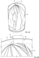
- Figures 4A-5B show a dewar constructed according to the present invention, where the collar 7 of the outer head has been subjected to excessive loading via a force perpendicular to the neck axis (arrow 16 in Figure 4B ). It can be seen there that the central region 10 of the outer head has deformed around the joint between the neck 14 and the collar 7. More specifically, the neck axis (15 of Figure 3 ) is no longer aligned on the original head axis (12 in Figure 2 ), and the central region material is displaced up on the left (20 in Figure 4B ) and down on the right (22 in Figure 4B ) in the sectioned dewar, relative to the original form.
- Figures 5A and 5B show a dewar constructed according to the present invention that has been subjected to excessive loading via a force along the neck axis (arrow 24). It can be seen there at 26 that the outer upper head central region material is displaced circumferentially down all around the joint between the neck 14 and the collar 7 (the inner vessel has moved downward relative to the outer vessel).
- Figure 6 illustrates an un-sectioned view of an alternative embodiment of a dewar of the disclosure showing the high-shouldered upper head 30 with the arcuate or shallow dish shaped crowning or central region 32.
- Figure 7 illustrates a prior art dewar of conventional construction, with a high, stiff upper head central region 34.
Landscapes
- Engineering & Computer Science (AREA)
- Mechanical Engineering (AREA)
- General Engineering & Computer Science (AREA)
- Physics & Mathematics (AREA)
- Thermal Sciences (AREA)
- Chemical & Material Sciences (AREA)
- Combustion & Propulsion (AREA)
- Filling Or Discharging Of Gas Storage Vessels (AREA)
- Packages (AREA)
- Devices For Use In Laboratory Experiments (AREA)
- Saccharide Compounds (AREA)
Description
- This application claims the benefit of
U.S. Provisional Application No. 62/439,377, filed December 27, 2016 - The present disclosure relates generally to cryogenic fluid containers and, in particular, to a dewar featuring a shock-survivable construction.
- Containers called dewars are used for storage and transport of cryogenic materials at very low temperatures (e.g., liquid nitrogen boils at 77K or -196C at normal pressure). They are necessarily constructed with minimal thermal connections, including an evacuated space, between an outer vessel and inner vessel that contains the cryogenic materials (often liquid nitrogen, also called LN2, and some valuable items or matter that must be kept cold by the LN2 as it evaporates from the minor heat leak into the inner vessel from the outside world). The space between the vessels is evacuated to eliminate convective and conductive heat transport.
- The only unavoidable connection between inner and outer vessels in a dewar is a neck opening to allow filling and emptying of the inner vessel from the outside world. Preferably, these necks are the only such connection, such that the inner vessel and all its contents are suspended exclusively through that neck attached to the outside vessel's top region.
- The dewar necks are beneficially made from low-conductivity materials and are further as thin as possible, to minimize conductive heat leak along the neck. Unfortunately, such low-conductivity materials (e.g., glass-fiber reinforced epoxy resin) are brittle as well. Because they serve as the primary structural connection between inner and outer vessel, these brittle necks can fail, either by breaking or separating at their attachment to the vessels, when the dewar is subjected to shocks such as sudden accelerations or decelerations as can happen during rough handling in shipping or transport. An example of such a dewar can be seen in
US Patent No. 4,572,402 . - Such dewar neck failings destroy the vacuum between the inner and outer vessels, leading to a rapid rise in thermal convection between the outside vessel at near-ambient temperature and the cold inner vessel. With that added heat input, any liquid in the inner vessel rapidly boils and can eject a jet of still-cold gas and/or liquid, which is undesirable.
- Further, a loss of insulating vacuum can mean the loss of the valuable materials in the dewar that are damaged by warming. More specifically, many small dewars are used in shipping and transport applications, such as agricultural semen distribution, transport of laboratory bio-samples, and other temperature-sensitive products. In some cases, where transported materials are rare or unique (e.g., elements of long-term medical studies for cancer); loss of vacuum and those contents is extremely expensive if not catastrophic to the owners of the contents.
- In the event of such damage and loss, there is always some question as to whether the shipping company is at fault for mishandling the dewar, or the dewar itself has failed due to a manufacturing or design defect. Providing a more robust dewar which does not fail under most frequently experienced handling loads, but reveals visible indications of loads in excess of standard design and shipping handling allowances, could reduce both losses and the effort and expense of identifying the root cause of such losses.
- Indicators of extreme handling of dewars exist in the form of small add-on products. When attached to a package, the product uses a visual indicator showing if the package has tipped from near 90 degrees or greater, or beyond the manufacturer's limits. These add-on indicators do not however, register excessive accelerations or decelerations (shock).
- There are also add-on indicators of excessive accelerations and decelerations, such as "shock indicators." These add-on indicators have pre-set shock limits based upon the users' requirements, and they utilize a visual display to indicate if a minimum shock limit was exceeded.
- These add-on products are very useful and are widely used in the logistics industry. However, these products do nothing to prevent product damage due to the orientation of the package or excessive shock. BRIEF DESCRIPTION OF THE
-
-
Figure 1 is a cross sectional view of a prior art outer vessel upper head; -
Figure 2A is a front elevational view of an outer vessel upper head in an embodiment of the disclosure; -
Figure 2B is an enlarged partial view of the upper head ofFigure 2A ; -
Figure 3 is a cross sectional side elevational view of a dewar including the outer vessel upper head ofFigures 2A and 2B in an embodiment of the disclosure; -
Figure 4A is a cutaway view of a dewar constructed in accordance with an embodiment of the disclosure that has been subjected to excessive loading perpendicular to the neck axis; -
Figure 4B is an enlarged view of the top portion of the dewar ofFig. 4A ; -
Figure 5A is a cutaway view of a dewar constructed in accordance with an embodiment of the disclosure that has been subjected to excessive loading along the neck axis; -
Figure 5B is an enlarged view of the top portion of the dewar ofFig. 5A ; -
Figure 6 is a perspective view of a dewar constructed in accordance with an embodiment of the disclosure; -
Figure 7 is a perspective view of a prior art dewar. - The invention concerns a dewar in accordance with
independent claim 1. - Prior art dewars are typically constructed of end pieces called 'heads' formed from flat aluminum alloy. The heads are welded to form an inner and an outer vessel, each consisting of an upper head and a lower head, with a neck attached and protruding from the inner vessel's upper head and extending to the outer vessel's upper head. The inner vessel is assembled and welded first. The inner vessel is then wrapped with multi-layer radiant-reflective material and inserted into a partly complete outer vessel. The outer vessel then receives its upper head, which is welded on, so that an interior chamber containing the inner vessel is formed. The final joint between the neck and the outer vessel upper head (typically a collar portion) is then completed using adhesive or other fastening methods known in the art. The insulation space between the inner and outer vessels is then evacuated to complete the thermal isolation of the inner vessel.
- An embodiment of a dewar constructed in accordance with the present invention is illustrated in
Figure 3 and includes aninner vessel 18 positioned within anouter vessel 20 with aninsulation space 22 formed between that is preferably evacuated of air to provide vacuum insulation. Aneck 14 extends between theinner vessel 18 and theouter vessel 20 and is secured by its upper end to thecollar 7 of the outer vessel upper head. The dewar ofFigure 3 also features additional construction details and features to provide upper head deformation prior to neck breakage as described below. - Finished dewars are typically boxed and may be shipped individually or on pallets to minimize tumbling during shipment. Some of the cryogenic dewars will spend their service life in stationary conditions, while other models are intended for repeated travel through shipping handlers, for the transport of cold, cryogenic materials, with, as an example only, liquid nitrogen inside the dewar, keeping the transported materials cold. These "shipper dewars" may not even be in cardboard boxes, but rather may be handled directly. They may be lifted, slung, tipped, dropped, or banged into other objects. The neck should be strong enough to withstand all such handling in the normal course of usage.
- Sometimes, dewar handling includes excessively rough treatment, with shocks or accelerations/decelerations above accepted norms of shipment jostle, as broadly defined by the International Safe Transit Association (ISTA). Although packaging of a product should meet the general guidelines of the ISTA, no cost-effective packaging will protect every product from every possible excessive shock encountered daily in the shipping world.
- Prior art dewars are typically made with outer upper heads, an example of which is illustrated in
Figure 1 , with high crowns or central regions 8 (deep dishes) to minimize the material required to bear the pressure load of atmosphere against vacuum. Such stamped and spun heads are heavily work-hardened by the 2-step manufacturing process, adding to the strength and rigidity of the head. While beneficial to the pressure loading, this strong rigidity makes the next weakest element in the structure, the attached brittle neck, the most likely failure point when excessively high shock loads are encountered. Yet a broken neck shows no sign of the cause of its demise. - An outer upper head constructed in accordance with the present invention is indicated in general at 9 in
Figure 2A . The head is preferably fully hydraulic press-formed, producing a lesser and more uniform work-hardening of the material in the central region (or crown) 10 near the neck (surrounding collar 7), where the central region is shaped as a shallow dish. As non-limiting examples only, as illustrated inFigures 2A and 2B , thecentral region 10 may feature an arcuate cross-section and/or may include a portion having an angle (13 inFigure 2B ) less than approximately 23° with respect to the horizontal axis (indicated at 11 inFigure 2B ). The rim regions of the outer upper head (17A, 17B and 17C ofFigure 2A ), which circumferentially surround thecentral region 10, retain their deeper dish shape for resisting pressure loads. - The construction of
Figures 2A and 2B means thecentral region 10 of the head is more elastic in a direction along its axis (indicated at 12 inFigure 2A ) or if a torque is applied perpendicular to that axis, the central region can absorb some energy that would otherwise be translated fully to the neck, thus preserving the neck from failing under normally encountered loads. - While such normally encountered loads will not plastically deform the outer head so constructed, the shape and temper of the alloy is chosen so as to induce permanent deformation in the region adjacent to the neck when excessive loads are applied, and still without overloading and breaking the neck (where the neck is indicated at 14 in
Figures 3 and5B , and the longitudinal axis of the neck, which is normally aligned withaxis 12 ofFigure 2A , is indicated at 15 inFigure 3 ). In this way, the vacuum is preserved in all but the most severe loads, but the unit is visibly marked by the permanent deformation, as explained below, to indicate that it has suffered such an excessive shock load. As non-limiting examples only, the outer upper head may be constructed from 5052-0 aluminum and theneck 14 may be constructed of glass-fiber reinforced epoxy resin. The dimensions ofFigure 3 are provided as non-limiting examples only. - Examples of the above effects are shown in
Figures 4A-5B .Figures 4A and 4B show a dewar constructed according to the present invention, where thecollar 7 of the outer head has been subjected to excessive loading via a force perpendicular to the neck axis (arrow 16 inFigure 4B ). It can be seen there that thecentral region 10 of the outer head has deformed around the joint between theneck 14 and thecollar 7. More specifically, the neck axis (15 ofFigure 3 ) is no longer aligned on the original head axis (12 inFigure 2 ), and the central region material is displaced up on the left (20 inFigure 4B ) and down on the right (22 inFigure 4B ) in the sectioned dewar, relative to the original form. -
Figures 5A and 5B show a dewar constructed according to the present invention that has been subjected to excessive loading via a force along the neck axis (arrow 24). It can be seen there at 26 that the outer upper head central region material is displaced circumferentially down all around the joint between theneck 14 and the collar 7 (the inner vessel has moved downward relative to the outer vessel). - Each of the deformations of
Figures 4A-5B is permanent (non-elastic), providing visible evidence from the outside that excessive loads have been applied. Further, in neither case, has theglass fiber neck 14 or its attachments to either vessel suffered any failure, so vacuum was preserved through the damage (prior to the sectioning performed to createFigures 4A-5B ). -
Figure 6 illustrates an un-sectioned view of an alternative embodiment of a dewar of the disclosure showing the high-shoulderedupper head 30 with the arcuate or shallow dish shaped crowning orcentral region 32.Figure 7 illustrates a prior art dewar of conventional construction, with a high, stiff upper headcentral region 34. - The above embodiments provide a dewar with maximum thermal performance as-built, but which can survive a much higher level of shock load without loss of vacuum, and thereby improve both safety and protection of stored materials through such shock loading events. The above embodiments provide a tell-tale indication after any such loading event to make evident to any observer that a dewar has undergone such a heavy loading and should be replaced or retired from transport use.
- While the preferred embodiments of the disclosure have been shown and described, it will be apparent to those skilled in the art that changes and modifications may be made therein without departing from the scope of the appended claims.
Claims (9)
- A dewar for storing a cryogenic fluid comprising:a. an inner vessel (18) configured to store the cryogenic fluid;b. an outer vessel (20) including an outer upper head (9, 30) and an outer lower head, said outer upper head including a central region (10, 32) and said outer upper and lower heads joined so as to define an interior chamber;c. the inner vessel positioned within the interior chamber of the outer vessel so that an insulation space (22) is defined between the inner and outer vessels, where the insulation space is evacuated of air;d. a neck (14) extending between and attached to the inner vessel and the central region of the outer upper head;
and characterized in thate. said outer upper head and neck are configured so that the central region permanently deforms, thus preserving the neck, when excessive shock loads are applied to the dewar,the central region including a shallow dish shape, the outer upper head further including rim regions (17A-C) which circumferentially surround the central region and include a deeper dish shape;the central region (10, 32) includes a portion having an angle (13) with respect to an axis (11) perpendicular to a longitudinal axis (12) of the neck,the central region (10, 32) features an arcuate cross-section. - The dewar of claim 1 wherein the outer upper head is fully hydraulic press-formed.
- The dewar of either one of claims 1 and 2 wherein the outer vessel is constructed of aluminum alloy.
- The dewar of any preceding claim, wherein the neck is constructed of glass-fiber reinforced epoxy resin.
- The dewar of any preceding claim, wherein the central region of the outer upper head features an arcuate cross-section.
- The dewar of any preceding claim, wherein the angle is less than 23°.
- The dewar of any preceding claim, wherein the outer upper head and neck are configured to preserve the neck when an excessive shock load including a force (24) parallel to a longitudinal axis (11) of the neck and/or a force (16) perpendicular to the longitudinal axis of the neck is applied to the dewar.
- The dewar of any preceding claim, wherein the outer upper head is configured having a shape and material temper that induces permanent deformation in the central region when excessive shock loads are applied.
- The dewar of any preceding claim, wherein the inner vessel includes an inner upper head and an inner lower head that are joined together.
Applications Claiming Priority (2)
| Application Number | Priority Date | Filing Date | Title |
|---|---|---|---|
| US201662439377P | 2016-12-27 | 2016-12-27 | |
| PCT/US2017/068149 WO2018125792A1 (en) | 2016-12-27 | 2017-12-22 | Shock resistant dewar vessel |
Publications (3)
| Publication Number | Publication Date |
|---|---|
| EP3563081A1 EP3563081A1 (en) | 2019-11-06 |
| EP3563081C0 EP3563081C0 (en) | 2024-08-14 |
| EP3563081B1 true EP3563081B1 (en) | 2024-08-14 |
Family
ID=60997569
Family Applications (1)
| Application Number | Title | Priority Date | Filing Date |
|---|---|---|---|
| EP17830083.6A Active EP3563081B1 (en) | 2016-12-27 | 2017-12-22 | Shock resistant dewar vessel |
Country Status (8)
| Country | Link |
|---|---|
| US (1) | US11300345B2 (en) |
| EP (1) | EP3563081B1 (en) |
| JP (1) | JP7236383B2 (en) |
| KR (1) | KR102414007B1 (en) |
| CN (1) | CN110325786B (en) |
| AU (1) | AU2017387025B2 (en) |
| CA (1) | CA3046099C (en) |
| WO (1) | WO2018125792A1 (en) |
Families Citing this family (2)
| Publication number | Priority date | Publication date | Assignee | Title |
|---|---|---|---|---|
| RU202559U1 (en) * | 2020-11-13 | 2021-02-24 | Общество с ограниченной ответственностью "Научно-производственное объединение "Криомаш" | Fiberglass Dewar Neck |
| US11933457B2 (en) * | 2022-05-09 | 2024-03-19 | MVE Biological Solutions US, LLC | One-piece neck tube |
Citations (5)
| Publication number | Priority date | Publication date | Assignee | Title |
|---|---|---|---|---|
| US2845199A (en) * | 1955-01-06 | 1958-07-29 | Mine Safety Appliances Co | Container |
| US3698589A (en) * | 1969-12-29 | 1972-10-17 | Union Carbide Corp | Cryogenic storage apparatus |
| DE3112134A1 (en) * | 1980-12-22 | 1982-07-29 | Herbert Prof.Dr. 1130 Wien Mang | Autoclave |
| US20040089580A1 (en) * | 2002-11-06 | 2004-05-13 | Hitoshi Ueda | Double-layer vacuum container |
| US8181813B2 (en) * | 2007-03-29 | 2012-05-22 | St Reproductive Technologies Llc | Transportation and/or storage device comprising a double-walled insulating bulb |
Family Cites Families (20)
| Publication number | Priority date | Publication date | Assignee | Title |
|---|---|---|---|---|
| US3101862A (en) * | 1958-01-15 | 1963-08-27 | Union Carbide Corp | Container construction using load carrying insulation |
| DE1501736A1 (en) * | 1966-09-24 | 1969-10-30 | Max Planck Gesellschaft | Stationary storage tank with a large capacity for storing liquefied gases |
| DE1919702A1 (en) | 1969-04-18 | 1970-11-26 | Bosch Gmbh Robert | Method for reducing the response time of solenoid valves |
| US4548335A (en) * | 1982-06-25 | 1985-10-22 | Minnesota Valley Engineering, Inc. | Liquid container |
| FR2529293A1 (en) * | 1982-06-29 | 1983-12-30 | Air Liquide | PROCESS FOR MANUFACTURING A HIGH THERMAL INSULATION CONTAINER |
| DE3525464A1 (en) * | 1985-07-17 | 1987-01-29 | Messer Griesheim Gmbh | DOUBLE-WALLED INSULATED CONTAINER FOR THE STORAGE OF LOW-BOILED LIQUID GASES |
| JPH03150420A (en) * | 1989-11-08 | 1991-06-26 | Hitachi Ltd | Lubricating liquid supply device of shaft sealing device |
| JP3154630B2 (en) * | 1994-11-25 | 2001-04-09 | 三菱重工業株式会社 | Container molding method |
| US6029456A (en) | 1996-05-10 | 2000-02-29 | Zaiser; Lenoir E. | Convoluted neck tube for cryogenic storage vessels |
| JP2000081199A (en) | 1998-09-07 | 2000-03-21 | Mitsubishi Materials Corp | Liquefied gas container and method for producing the same |
| CN2449045Y (en) * | 2000-10-17 | 2001-09-19 | 薛英杰 | Top sealed end radial support for vertical Dewar bottle liner |
| JP3885566B2 (en) * | 2001-03-02 | 2007-02-21 | 株式会社デンソー | Metal vacuum double container |
| JP4717536B2 (en) * | 2005-07-12 | 2011-07-06 | 大陽日酸株式会社 | Low temperature liquefied gas storage tank |
| JP4962863B2 (en) | 2007-10-23 | 2012-06-27 | トヨタ自動車株式会社 | Impact recording medium for fuel tank and impact recording method |
| US9315881B2 (en) | 2008-10-03 | 2016-04-19 | Us Synthetic Corporation | Polycrystalline diamond, polycrystalline diamond compacts, methods of making same, and applications |
| JP4816737B2 (en) | 2009-01-27 | 2011-11-16 | トヨタ自動車株式会社 | tank |
| CN202442098U (en) * | 2012-02-03 | 2012-09-19 | 张家港中集圣达因低温装备有限公司 | Sandwich pipeline structure for small-volume cryogenic vessel and small-volume cryogenic vessel |
| CN103256481B (en) * | 2013-05-28 | 2015-09-16 | 常州大学 | The reinforcement end socket of vertical-type low-temperature heat-insulation gas cylinder shell |
| CN203743843U (en) * | 2013-12-31 | 2014-07-30 | 常州博朗低温设备有限公司 | Structure for connecting internal container and external container of low-temperature liquid storage tank |
| JP7013533B1 (en) | 2020-08-06 | 2022-02-15 | ヤス カンパニー リミテッド | Optimized length mask frame |
-
2017
- 2017-12-22 AU AU2017387025A patent/AU2017387025B2/en active Active
- 2017-12-22 JP JP2019531723A patent/JP7236383B2/en active Active
- 2017-12-22 CN CN201780080658.XA patent/CN110325786B/en active Active
- 2017-12-22 US US15/852,224 patent/US11300345B2/en active Active
- 2017-12-22 CA CA3046099A patent/CA3046099C/en active Active
- 2017-12-22 WO PCT/US2017/068149 patent/WO2018125792A1/en not_active Ceased
- 2017-12-22 EP EP17830083.6A patent/EP3563081B1/en active Active
- 2017-12-22 KR KR1020197018395A patent/KR102414007B1/en active Active
Patent Citations (5)
| Publication number | Priority date | Publication date | Assignee | Title |
|---|---|---|---|---|
| US2845199A (en) * | 1955-01-06 | 1958-07-29 | Mine Safety Appliances Co | Container |
| US3698589A (en) * | 1969-12-29 | 1972-10-17 | Union Carbide Corp | Cryogenic storage apparatus |
| DE3112134A1 (en) * | 1980-12-22 | 1982-07-29 | Herbert Prof.Dr. 1130 Wien Mang | Autoclave |
| US20040089580A1 (en) * | 2002-11-06 | 2004-05-13 | Hitoshi Ueda | Double-layer vacuum container |
| US8181813B2 (en) * | 2007-03-29 | 2012-05-22 | St Reproductive Technologies Llc | Transportation and/or storage device comprising a double-walled insulating bulb |
Also Published As
| Publication number | Publication date |
|---|---|
| AU2017387025B2 (en) | 2022-07-28 |
| US11300345B2 (en) | 2022-04-12 |
| JP7236383B2 (en) | 2023-03-09 |
| AU2017387025A1 (en) | 2019-06-27 |
| KR102414007B1 (en) | 2022-06-28 |
| JP2020504799A (en) | 2020-02-13 |
| KR20190097072A (en) | 2019-08-20 |
| US20180180342A1 (en) | 2018-06-28 |
| CA3046099A1 (en) | 2018-07-05 |
| EP3563081C0 (en) | 2024-08-14 |
| CN110325786A (en) | 2019-10-11 |
| EP3563081A1 (en) | 2019-11-06 |
| CN110325786B (en) | 2022-07-01 |
| WO2018125792A1 (en) | 2018-07-05 |
| CA3046099C (en) | 2023-11-14 |
Similar Documents
| Publication | Publication Date | Title |
|---|---|---|
| JP5124633B2 (en) | Transport and / or storage device with double wall insulated spheres | |
| CN106574744B (en) | Shelf support for double-wall cryogenic storage containers | |
| CA3046099C (en) | Shock resistant dewar vessel | |
| US20080067178A1 (en) | Portable tank and tank container for liquefied gas transportation | |
| ES2401747T3 (en) | Packaging sets and internal support structure for the transport and storage of radioactive materials | |
| US20080197105A1 (en) | Container, in Particular a Bottle, Made of Thermoplastic Material | |
| CN113167438A (en) | Liquefied gas supporting device and storage container | |
| JP6548577B2 (en) | Package for transport and storage of radioactive material, including improved means for mounting a shock absorber cover | |
| US20170159883A1 (en) | Cryogenic tank and method of storing cryogenic liquids | |
| CN108473183A (en) | It is used in particular for more housing units of seaborne compressed gas cylinder | |
| KR20250060892A (en) | A new system for transporting cryogenic frozen materials | |
| US20170047134A1 (en) | Packaging for transporting and/or storing radioactive material, comprising a more effective corner shock absorber | |
| US11933457B2 (en) | One-piece neck tube | |
| RU2378610C1 (en) | Package for ammunition | |
| JP6807207B2 (en) | Plastic bottle | |
| WO2017091223A1 (en) | Composite pressure vessel assembly with an integrated heating element | |
| KR101630970B1 (en) | Insulating materials combinational structure and manufacturing method for storage tank | |
| EP3093548A1 (en) | Protective casing for cylinder for pressurized gases | |
| HK1136861B (en) | Transportation and/or storage device comprising a double-walled insulating bulb | |
| KR101885913B1 (en) | Liquefied natural gas storage tank | |
| PL220423B1 (en) | Gas cylinder |
Legal Events
| Date | Code | Title | Description |
|---|---|---|---|
| STAA | Information on the status of an ep patent application or granted ep patent |
Free format text: STATUS: UNKNOWN |
|
| STAA | Information on the status of an ep patent application or granted ep patent |
Free format text: STATUS: THE INTERNATIONAL PUBLICATION HAS BEEN MADE |
|
| PUAI | Public reference made under article 153(3) epc to a published international application that has entered the european phase |
Free format text: ORIGINAL CODE: 0009012 |
|
| STAA | Information on the status of an ep patent application or granted ep patent |
Free format text: STATUS: REQUEST FOR EXAMINATION WAS MADE |
|
| 17P | Request for examination filed |
Effective date: 20190723 |
|
| AK | Designated contracting states |
Kind code of ref document: A1 Designated state(s): AL AT BE BG CH CY CZ DE DK EE ES FI FR GB GR HR HU IE IS IT LI LT LU LV MC MK MT NL NO PL PT RO RS SE SI SK SM TR |
|
| AX | Request for extension of the european patent |
Extension state: BA ME |
|
| DAV | Request for validation of the european patent (deleted) | ||
| DAX | Request for extension of the european patent (deleted) | ||
| RAP1 | Party data changed (applicant data changed or rights of an application transferred) |
Owner name: MVE BIOLOGICAL SOLUTIONS US |
|
| STAA | Information on the status of an ep patent application or granted ep patent |
Free format text: STATUS: EXAMINATION IS IN PROGRESS |
|
| 17Q | First examination report despatched |
Effective date: 20220316 |
|
| GRAP | Despatch of communication of intention to grant a patent |
Free format text: ORIGINAL CODE: EPIDOSNIGR1 |
|
| STAA | Information on the status of an ep patent application or granted ep patent |
Free format text: STATUS: GRANT OF PATENT IS INTENDED |
|
| INTG | Intention to grant announced |
Effective date: 20240315 |
|
| GRAS | Grant fee paid |
Free format text: ORIGINAL CODE: EPIDOSNIGR3 |
|
| GRAA | (expected) grant |
Free format text: ORIGINAL CODE: 0009210 |
|
| STAA | Information on the status of an ep patent application or granted ep patent |
Free format text: STATUS: THE PATENT HAS BEEN GRANTED |
|
| AK | Designated contracting states |
Kind code of ref document: B1 Designated state(s): AL AT BE BG CH CY CZ DE DK EE ES FI FR GB GR HR HU IE IS IT LI LT LU LV MC MK MT NL NO PL PT RO RS SE SI SK SM TR |
|
| REG | Reference to a national code |
Ref country code: GB Ref legal event code: FG4D |
|
| REG | Reference to a national code |
Ref country code: CH Ref legal event code: EP |
|
| REG | Reference to a national code |
Ref country code: DE Ref legal event code: R096 Ref document number: 602017084121 Country of ref document: DE |
|
| REG | Reference to a national code |
Ref country code: IE Ref legal event code: FG4D |
|
| U01 | Request for unitary effect filed |
Effective date: 20240821 |
|
| U07 | Unitary effect registered |
Designated state(s): AT BE BG DE DK EE FI FR IT LT LU LV MT NL PT RO SE SI Effective date: 20240902 |
|
| PG25 | Lapsed in a contracting state [announced via postgrant information from national office to epo] |
Ref country code: NO Free format text: LAPSE BECAUSE OF FAILURE TO SUBMIT A TRANSLATION OF THE DESCRIPTION OR TO PAY THE FEE WITHIN THE PRESCRIBED TIME-LIMIT Effective date: 20241114 |
|
| U20 | Renewal fee for the european patent with unitary effect paid |
Year of fee payment: 8 Effective date: 20241209 |
|
| PG25 | Lapsed in a contracting state [announced via postgrant information from national office to epo] |
Ref country code: PL Free format text: LAPSE BECAUSE OF FAILURE TO SUBMIT A TRANSLATION OF THE DESCRIPTION OR TO PAY THE FEE WITHIN THE PRESCRIBED TIME-LIMIT Effective date: 20240814 Ref country code: GR Free format text: LAPSE BECAUSE OF FAILURE TO SUBMIT A TRANSLATION OF THE DESCRIPTION OR TO PAY THE FEE WITHIN THE PRESCRIBED TIME-LIMIT Effective date: 20241115 |
|
| PG25 | Lapsed in a contracting state [announced via postgrant information from national office to epo] |
Ref country code: IS Free format text: LAPSE BECAUSE OF FAILURE TO SUBMIT A TRANSLATION OF THE DESCRIPTION OR TO PAY THE FEE WITHIN THE PRESCRIBED TIME-LIMIT Effective date: 20241214 |
|
| PG25 | Lapsed in a contracting state [announced via postgrant information from national office to epo] |
Ref country code: HR Free format text: LAPSE BECAUSE OF FAILURE TO SUBMIT A TRANSLATION OF THE DESCRIPTION OR TO PAY THE FEE WITHIN THE PRESCRIBED TIME-LIMIT Effective date: 20240814 |
|
| PG25 | Lapsed in a contracting state [announced via postgrant information from national office to epo] |
Ref country code: RS Free format text: LAPSE BECAUSE OF FAILURE TO SUBMIT A TRANSLATION OF THE DESCRIPTION OR TO PAY THE FEE WITHIN THE PRESCRIBED TIME-LIMIT Effective date: 20241114 Ref country code: ES Free format text: LAPSE BECAUSE OF FAILURE TO SUBMIT A TRANSLATION OF THE DESCRIPTION OR TO PAY THE FEE WITHIN THE PRESCRIBED TIME-LIMIT Effective date: 20240814 |
|
| PG25 | Lapsed in a contracting state [announced via postgrant information from national office to epo] |
Ref country code: RS Free format text: LAPSE BECAUSE OF FAILURE TO SUBMIT A TRANSLATION OF THE DESCRIPTION OR TO PAY THE FEE WITHIN THE PRESCRIBED TIME-LIMIT Effective date: 20241114 Ref country code: PL Free format text: LAPSE BECAUSE OF FAILURE TO SUBMIT A TRANSLATION OF THE DESCRIPTION OR TO PAY THE FEE WITHIN THE PRESCRIBED TIME-LIMIT Effective date: 20240814 Ref country code: NO Free format text: LAPSE BECAUSE OF FAILURE TO SUBMIT A TRANSLATION OF THE DESCRIPTION OR TO PAY THE FEE WITHIN THE PRESCRIBED TIME-LIMIT Effective date: 20241114 Ref country code: IS Free format text: LAPSE BECAUSE OF FAILURE TO SUBMIT A TRANSLATION OF THE DESCRIPTION OR TO PAY THE FEE WITHIN THE PRESCRIBED TIME-LIMIT Effective date: 20241214 Ref country code: HR Free format text: LAPSE BECAUSE OF FAILURE TO SUBMIT A TRANSLATION OF THE DESCRIPTION OR TO PAY THE FEE WITHIN THE PRESCRIBED TIME-LIMIT Effective date: 20240814 Ref country code: GR Free format text: LAPSE BECAUSE OF FAILURE TO SUBMIT A TRANSLATION OF THE DESCRIPTION OR TO PAY THE FEE WITHIN THE PRESCRIBED TIME-LIMIT Effective date: 20241115 Ref country code: ES Free format text: LAPSE BECAUSE OF FAILURE TO SUBMIT A TRANSLATION OF THE DESCRIPTION OR TO PAY THE FEE WITHIN THE PRESCRIBED TIME-LIMIT Effective date: 20240814 |
|
| PG25 | Lapsed in a contracting state [announced via postgrant information from national office to epo] |
Ref country code: SM Free format text: LAPSE BECAUSE OF FAILURE TO SUBMIT A TRANSLATION OF THE DESCRIPTION OR TO PAY THE FEE WITHIN THE PRESCRIBED TIME-LIMIT Effective date: 20240814 |
|
| PG25 | Lapsed in a contracting state [announced via postgrant information from national office to epo] |
Ref country code: CZ Free format text: LAPSE BECAUSE OF FAILURE TO SUBMIT A TRANSLATION OF THE DESCRIPTION OR TO PAY THE FEE WITHIN THE PRESCRIBED TIME-LIMIT Effective date: 20240814 |
|
| PG25 | Lapsed in a contracting state [announced via postgrant information from national office to epo] |
Ref country code: SK Free format text: LAPSE BECAUSE OF FAILURE TO SUBMIT A TRANSLATION OF THE DESCRIPTION OR TO PAY THE FEE WITHIN THE PRESCRIBED TIME-LIMIT Effective date: 20240814 |
|
| PLBE | No opposition filed within time limit |
Free format text: ORIGINAL CODE: 0009261 |
|
| STAA | Information on the status of an ep patent application or granted ep patent |
Free format text: STATUS: NO OPPOSITION FILED WITHIN TIME LIMIT |
|
| PG25 | Lapsed in a contracting state [announced via postgrant information from national office to epo] |
Ref country code: MC Free format text: LAPSE BECAUSE OF FAILURE TO SUBMIT A TRANSLATION OF THE DESCRIPTION OR TO PAY THE FEE WITHIN THE PRESCRIBED TIME-LIMIT Effective date: 20240814 |
|
| 26N | No opposition filed |
Effective date: 20250515 |
|
| REG | Reference to a national code |
Ref country code: CH Ref legal event code: PL |
|
| PG25 | Lapsed in a contracting state [announced via postgrant information from national office to epo] |
Ref country code: CH Free format text: LAPSE BECAUSE OF NON-PAYMENT OF DUE FEES Effective date: 20241231 |
|
| PG25 | Lapsed in a contracting state [announced via postgrant information from national office to epo] |
Ref country code: IE Free format text: LAPSE BECAUSE OF NON-PAYMENT OF DUE FEES Effective date: 20241222 |
|
| PGFP | Annual fee paid to national office [announced via postgrant information from national office to epo] |
Ref country code: GB Payment date: 20251218 Year of fee payment: 9 |
|
| U20 | Renewal fee for the european patent with unitary effect paid |
Year of fee payment: 9 Effective date: 20251229 |
|
| PG25 | Lapsed in a contracting state [announced via postgrant information from national office to epo] |
Ref country code: CY Free format text: LAPSE BECAUSE OF FAILURE TO SUBMIT A TRANSLATION OF THE DESCRIPTION OR TO PAY THE FEE WITHIN THE PRESCRIBED TIME-LIMIT Effective date: 20240814 |