EP3562722B1 - Method for controlling a braking action applicable by a brake caliper on a mechanical movement member of a vehicle and system thereof - Google Patents
Method for controlling a braking action applicable by a brake caliper on a mechanical movement member of a vehicle and system thereof Download PDFInfo
- Publication number
- EP3562722B1 EP3562722B1 EP17832572.6A EP17832572A EP3562722B1 EP 3562722 B1 EP3562722 B1 EP 3562722B1 EP 17832572 A EP17832572 A EP 17832572A EP 3562722 B1 EP3562722 B1 EP 3562722B1
- Authority
- EP
- European Patent Office
- Prior art keywords
- actuator assembly
- brake caliper
- control unit
- actuator
- electronic control
- Prior art date
- Legal status (The legal status is an assumption and is not a legal conclusion. Google has not performed a legal analysis and makes no representation as to the accuracy of the status listed.)
- Active
Links
Images



Classifications
-
- B—PERFORMING OPERATIONS; TRANSPORTING
- B60—VEHICLES IN GENERAL
- B60T—VEHICLE BRAKE CONTROL SYSTEMS OR PARTS THEREOF; BRAKE CONTROL SYSTEMS OR PARTS THEREOF, IN GENERAL; ARRANGEMENT OF BRAKING ELEMENTS ON VEHICLES IN GENERAL; PORTABLE DEVICES FOR PREVENTING UNWANTED MOVEMENT OF VEHICLES; VEHICLE MODIFICATIONS TO FACILITATE COOLING OF BRAKES
- B60T13/00—Transmitting braking action from initiating means to ultimate brake actuator with power assistance or drive; Brake systems incorporating such transmitting means, e.g. air-pressure brake systems
- B60T13/74—Transmitting braking action from initiating means to ultimate brake actuator with power assistance or drive; Brake systems incorporating such transmitting means, e.g. air-pressure brake systems with electrical assistance or drive
- B60T13/741—Transmitting braking action from initiating means to ultimate brake actuator with power assistance or drive; Brake systems incorporating such transmitting means, e.g. air-pressure brake systems with electrical assistance or drive acting on an ultimate actuator
-
- B—PERFORMING OPERATIONS; TRANSPORTING
- B60—VEHICLES IN GENERAL
- B60T—VEHICLE BRAKE CONTROL SYSTEMS OR PARTS THEREOF; BRAKE CONTROL SYSTEMS OR PARTS THEREOF, IN GENERAL; ARRANGEMENT OF BRAKING ELEMENTS ON VEHICLES IN GENERAL; PORTABLE DEVICES FOR PREVENTING UNWANTED MOVEMENT OF VEHICLES; VEHICLE MODIFICATIONS TO FACILITATE COOLING OF BRAKES
- B60T8/00—Arrangements for adjusting wheel-braking force to meet varying vehicular or ground-surface conditions, e.g. limiting or varying distribution of braking force
- B60T8/17—Using electrical or electronic regulation means to control braking
-
- B—PERFORMING OPERATIONS; TRANSPORTING
- B60—VEHICLES IN GENERAL
- B60T—VEHICLE BRAKE CONTROL SYSTEMS OR PARTS THEREOF; BRAKE CONTROL SYSTEMS OR PARTS THEREOF, IN GENERAL; ARRANGEMENT OF BRAKING ELEMENTS ON VEHICLES IN GENERAL; PORTABLE DEVICES FOR PREVENTING UNWANTED MOVEMENT OF VEHICLES; VEHICLE MODIFICATIONS TO FACILITATE COOLING OF BRAKES
- B60T13/00—Transmitting braking action from initiating means to ultimate brake actuator with power assistance or drive; Brake systems incorporating such transmitting means, e.g. air-pressure brake systems
- B60T13/10—Transmitting braking action from initiating means to ultimate brake actuator with power assistance or drive; Brake systems incorporating such transmitting means, e.g. air-pressure brake systems with fluid assistance, drive, or release
- B60T13/66—Electrical control in fluid-pressure brake systems
- B60T13/662—Electrical control in fluid-pressure brake systems characterised by specified functions of the control system components
-
- B—PERFORMING OPERATIONS; TRANSPORTING
- B60—VEHICLES IN GENERAL
- B60T—VEHICLE BRAKE CONTROL SYSTEMS OR PARTS THEREOF; BRAKE CONTROL SYSTEMS OR PARTS THEREOF, IN GENERAL; ARRANGEMENT OF BRAKING ELEMENTS ON VEHICLES IN GENERAL; PORTABLE DEVICES FOR PREVENTING UNWANTED MOVEMENT OF VEHICLES; VEHICLE MODIFICATIONS TO FACILITATE COOLING OF BRAKES
- B60T13/00—Transmitting braking action from initiating means to ultimate brake actuator with power assistance or drive; Brake systems incorporating such transmitting means, e.g. air-pressure brake systems
- B60T13/74—Transmitting braking action from initiating means to ultimate brake actuator with power assistance or drive; Brake systems incorporating such transmitting means, e.g. air-pressure brake systems with electrical assistance or drive
-
- B—PERFORMING OPERATIONS; TRANSPORTING
- B60—VEHICLES IN GENERAL
- B60T—VEHICLE BRAKE CONTROL SYSTEMS OR PARTS THEREOF; BRAKE CONTROL SYSTEMS OR PARTS THEREOF, IN GENERAL; ARRANGEMENT OF BRAKING ELEMENTS ON VEHICLES IN GENERAL; PORTABLE DEVICES FOR PREVENTING UNWANTED MOVEMENT OF VEHICLES; VEHICLE MODIFICATIONS TO FACILITATE COOLING OF BRAKES
- B60T13/00—Transmitting braking action from initiating means to ultimate brake actuator with power assistance or drive; Brake systems incorporating such transmitting means, e.g. air-pressure brake systems
- B60T13/74—Transmitting braking action from initiating means to ultimate brake actuator with power assistance or drive; Brake systems incorporating such transmitting means, e.g. air-pressure brake systems with electrical assistance or drive
- B60T13/745—Transmitting braking action from initiating means to ultimate brake actuator with power assistance or drive; Brake systems incorporating such transmitting means, e.g. air-pressure brake systems with electrical assistance or drive acting on a hydraulic system, e.g. a master cylinder
-
- B—PERFORMING OPERATIONS; TRANSPORTING
- B60—VEHICLES IN GENERAL
- B60T—VEHICLE BRAKE CONTROL SYSTEMS OR PARTS THEREOF; BRAKE CONTROL SYSTEMS OR PARTS THEREOF, IN GENERAL; ARRANGEMENT OF BRAKING ELEMENTS ON VEHICLES IN GENERAL; PORTABLE DEVICES FOR PREVENTING UNWANTED MOVEMENT OF VEHICLES; VEHICLE MODIFICATIONS TO FACILITATE COOLING OF BRAKES
- B60T13/00—Transmitting braking action from initiating means to ultimate brake actuator with power assistance or drive; Brake systems incorporating such transmitting means, e.g. air-pressure brake systems
- B60T13/74—Transmitting braking action from initiating means to ultimate brake actuator with power assistance or drive; Brake systems incorporating such transmitting means, e.g. air-pressure brake systems with electrical assistance or drive
- B60T13/746—Transmitting braking action from initiating means to ultimate brake actuator with power assistance or drive; Brake systems incorporating such transmitting means, e.g. air-pressure brake systems with electrical assistance or drive and mechanical transmission of the braking action
-
- F—MECHANICAL ENGINEERING; LIGHTING; HEATING; WEAPONS; BLASTING
- F16—ENGINEERING ELEMENTS AND UNITS; GENERAL MEASURES FOR PRODUCING AND MAINTAINING EFFECTIVE FUNCTIONING OF MACHINES OR INSTALLATIONS; THERMAL INSULATION IN GENERAL
- F16D—COUPLINGS FOR TRANSMITTING ROTATION; CLUTCHES; BRAKES
- F16D55/00—Brakes with substantially-radial braking surfaces pressed together in axial direction, e.g. disc brakes
- F16D55/02—Brakes with substantially-radial braking surfaces pressed together in axial direction, e.g. disc brakes with axially-movable discs or pads pressed against axially-located rotating members
- F16D55/22—Brakes with substantially-radial braking surfaces pressed together in axial direction, e.g. disc brakes with axially-movable discs or pads pressed against axially-located rotating members by clamping an axially-located rotating disc between movable braking members, e.g. movable brake discs or brake pads
- F16D55/224—Brakes with substantially-radial braking surfaces pressed together in axial direction, e.g. disc brakes with axially-movable discs or pads pressed against axially-located rotating members by clamping an axially-located rotating disc between movable braking members, e.g. movable brake discs or brake pads with a common actuating member for the braking members
- F16D55/225—Brakes with substantially-radial braking surfaces pressed together in axial direction, e.g. disc brakes with axially-movable discs or pads pressed against axially-located rotating members by clamping an axially-located rotating disc between movable braking members, e.g. movable brake discs or brake pads with a common actuating member for the braking members the braking members being brake pads
- F16D55/226—Brakes with substantially-radial braking surfaces pressed together in axial direction, e.g. disc brakes with axially-movable discs or pads pressed against axially-located rotating members by clamping an axially-located rotating disc between movable braking members, e.g. movable brake discs or brake pads with a common actuating member for the braking members the braking members being brake pads in which the common actuating member is moved axially, e.g. floating caliper disc brakes
-
- F—MECHANICAL ENGINEERING; LIGHTING; HEATING; WEAPONS; BLASTING
- F16—ENGINEERING ELEMENTS AND UNITS; GENERAL MEASURES FOR PRODUCING AND MAINTAINING EFFECTIVE FUNCTIONING OF MACHINES OR INSTALLATIONS; THERMAL INSULATION IN GENERAL
- F16D—COUPLINGS FOR TRANSMITTING ROTATION; CLUTCHES; BRAKES
- F16D65/00—Parts or details
- F16D65/14—Actuating mechanisms for brakes; Means for initiating operation at a predetermined position
- F16D65/16—Actuating mechanisms for brakes; Means for initiating operation at a predetermined position arranged in or on the brake
- F16D65/18—Actuating mechanisms for brakes; Means for initiating operation at a predetermined position arranged in or on the brake adapted for drawing members together, e.g. for disc brakes
- F16D65/183—Actuating mechanisms for brakes; Means for initiating operation at a predetermined position arranged in or on the brake adapted for drawing members together, e.g. for disc brakes with force-transmitting members arranged side by side acting on a spot type force-applying member
-
- B—PERFORMING OPERATIONS; TRANSPORTING
- B60—VEHICLES IN GENERAL
- B60T—VEHICLE BRAKE CONTROL SYSTEMS OR PARTS THEREOF; BRAKE CONTROL SYSTEMS OR PARTS THEREOF, IN GENERAL; ARRANGEMENT OF BRAKING ELEMENTS ON VEHICLES IN GENERAL; PORTABLE DEVICES FOR PREVENTING UNWANTED MOVEMENT OF VEHICLES; VEHICLE MODIFICATIONS TO FACILITATE COOLING OF BRAKES
- B60T2270/00—Further aspects of brake control systems not otherwise provided for
- B60T2270/82—Brake-by-Wire, EHB
-
- F—MECHANICAL ENGINEERING; LIGHTING; HEATING; WEAPONS; BLASTING
- F16—ENGINEERING ELEMENTS AND UNITS; GENERAL MEASURES FOR PRODUCING AND MAINTAINING EFFECTIVE FUNCTIONING OF MACHINES OR INSTALLATIONS; THERMAL INSULATION IN GENERAL
- F16D—COUPLINGS FOR TRANSMITTING ROTATION; CLUTCHES; BRAKES
- F16D2121/00—Type of actuator operation force
- F16D2121/18—Electric or magnetic
- F16D2121/24—Electric or magnetic using motors
Definitions
- the present invention relates to braking techniques of a vehicle and in particular to a method for controlling a braking action applicable by a brake caliper on a mechanical movement member of a vehicle and to a control system thereof.
- vehicle means a car, a motorcycle, a light commercial vehicle, a heavy industrial vehicle or any other vehicle in which it is necessary to apply a braking action on mechanical movement members (e.g. rotors or aircraft landing gear).
- mechanical movement members e.g. rotors or aircraft landing gear
- Braking system of the B-b-W (Brake-by-Wire) type have become more widespread over time; in braking systems of this type, the braking action of a brake caliper on a mechanical movement member is obtained by using one or more electro-mechanical or electro-hydraulic actuators.
- Such actuators contain one more electric motors, which, by means of a mechanical transmission, actuate a cylinder, which displaces a braking fluid, whereby generating a pressure which actuates, in turn, the brake caliper or by means of the mechanical transmission, act on one or more pistons, and therefore on the brake calipers.
- a standard configuration of an electro-mechanical or electro-hydraulic actuator of a B-b-W system comprises a linear mechanical transmission between the electric motor and the cylinder or piston to be moved.
- Examples of B-b-W systems known in the art are disclosed in GB 2 463 752 A , EP 1695887 A1 and US 2007/235267 A1 .
- the linear mechanical transmission may be replaced by a non-linear mechanical transmission, in which the mechanical transmission between the electric motor and the component to be moved (cylinder or piston) consists of one or more mechanical transmissions with variable transmission ratios.
- the electro-mechanical or electro-hydraulic actuator can maximize performance also in extreme conditions.
- one or more electronic components is needed which are configured to run a method for controlling the braking action applicable on a mechanical movement member by the electro-mechanical or electro-hydraulic actuator, by managing the electric power coming from a power source of the vehicle and transferred to the electro-mechanical or electro-hydraulic actuator, possibility in any working condition, even the most extreme.
- a system 100 for controlling a braking action applicable by a brake caliper on a mechanical movement member of a vehicle hereinafter also control system or simply system, according to the present invention, will firstly be described with reference to the aforesaid figures.
- the vehicle may be, for example, a car, a motorcycle, a light commercial vehicle, a heavy industrial vehicle or any other vehicle in which a braking action must be applied by actuating a brake caliper on mechanical movement members (e.g. rotors or aircraft landing gear).
- a brake caliper on mechanical movement members (e.g. rotors or aircraft landing gear).
- the vehicle 200 comprises at least one mechanical movement member R1 (e.g. a wheel), a first brake disc DB1 operatively associated with said at least one mechanical movement member R1 and a first brake caliper PZ1 which can be actuated to apply on said first brake disc DB1, then on said at least one mechanical movement member R1, a braking action, e.g. a dissipative braking torque.
- R1 e.g. a wheel
- first brake disc DB1 operatively associated with said at least one mechanical movement member R1
- a first brake caliper PZ1 which can be actuated to apply on said first brake disc DB1, then on said at least one mechanical movement member R1, a braking action, e.g. a dissipative braking torque.
- the vehicle 200 further comprises the system 100 for controlling a braking action applicable by the brake caliper PZ1 on said at least one mechanical movement member R1.
- the system 100 further comprises an electronic control unit 101 configured to execute a method for controlling the braking action applicable by a brake caliper PZ1 on a mechanical movement member R1 of a vehicle 100.
- the electronic control unit 101 may comprise one or more control modules or logics, e.g. microprocessors or microcontrollers, configured to execute the aforesaid control method as a whole.
- control modules or logics e.g. microprocessors or microcontrollers
- the system 100 further comprises an actuator assembly 102 of said at least one brake caliper PZ1, operatively connected to the electronic control unit 101.
- system 100 may comprise a further actuator assembly, entirely similar to the actuator assembly 102, of at least one second brake caliper (not shown in the figures), operatively connected to the electronic control unit 101.
- the vehicle 200 may comprise at least one further mechanical movement member (e.g. a further wheel, not shown in figure 1 ), a further brake disc (not shown in the figure 1 ) operatively associated with said at least one mechanical movement member and the further first brake caliper which can be actuated to apply a braking action, e.g. a dissipative braking torque on said further brake disc, thus on said at least one further mechanical movement member R1.
- a further mechanical movement member e.g. a further wheel, not shown in figure 1
- a further brake disc (not shown in the figure 1 ) operatively associated with said at least one mechanical movement member and the further first brake caliper which can be actuated to apply a braking action, e.g. a dissipative braking torque on said further brake disc, thus on said at least one further mechanical movement member R1.
- the at least one mechanical movement member R1 and the at least one further mechanical movement member may belong to the same axis of the vehicle 200, e.g. the front axle or the rear axle.
- the respective actuator assemblies (the at least one actuator assembly 102 and the further actuator assembly, respectively) are operatively connected to and controlled by the electronic control unit 101 itself.
- system 100 may comprise a further actuator assembly, entirely similar to the actuator assembly 102, for each brake caliper with which the vehicle 200 may be provided.
- Each brake caliper is operatively associated with a respective brake disc, on which to apply the braking action, operatively associated with a respective mechanical movement member, in turn.
- the actuator assemblies operatively connected to mechanical movement members belonging to the same vehicle axle (front or rear) are preferably controlled by the same electronic control unit.
- the actuator assembly 102 comprises at least one electric motor 103 and an actuator 104.
- the electric motor 103 is operatively connected to the electronic control unit 101 (not shown in figures 2 and 3 ) to receive a respective control signal from it.
- the electric motor 103 is operatively connected to the actuator 104 by means of a transmission mechanism 105.
- said transmission mechanism 105 is of non-linear type.
- Transmission mechanism of non-linear type means the set of one or more mechanisms having variable transmission ratio.
- An example of transmission mechanism of non-linear type is a rod-crack type mechanism.
- the translation speed of a translatable portion is a non-linear function of the angular position of a rotatable portion (e.g. the crank) and also of the stroke of the translatable portion.
- the pressure of a fluid inside the braking system is approximately a linear function of the stroke of a piston (actuatable by the translatable portion of the non-linear transmission mechanism connected to the actuator 104) and the combination of such linear function with the non-linear function of the translation speed of the piston makes it possible to obtain a non-linear ratio between the torque of the electric motor 103 and the stroke of the piston, in which, in a prevalent portion of the rear stretch (in the first half) of the stroke of the piston, the torque of the electric motor 103 increases in approximately proportional (linear) manner with the advancement of the piston and, on the front stretch (in the second half) of the stroke of the piston, the torque of the electric motor 103 increases in sub-proportional (or decreasing) manner or decreases with the advancement of the piston.
- a transmission mechanism of non-linear type makes it possible to advantageously obtain an optimal operation of the electric motor 103 and an accurate control of the fluid pressure in normal braking conditions (with the piston in the rear stretch of the stroke of the piston) and a very high pressurization of the fluid in exceptional braking conditions (with the piston in the front stretch of the stroke od the piston).
- the transmission mechanism may be of linear type.
- Transmission mechanism of linear type means the set of one or more mechanisms having fixed transmission ratio, e.g. a N:1 reduction ratio.
- An example of transmission mechanism of linear type is a cascade or planetary gear mechanism or a screw-nut screw mechanism.
- the electric motor 103 is configured to actuate the actuator 104 by means of the transmission mechanism 105.
- the actuator assembly 102 is of the electro-hydraulic type.
- the actuator 104 comprises one or more hydraulic cylinders.
- the actuation by the electric motor 103 of said one or more hydraulic cylinders generates inside the braking system the hydraulic pressure needed to move the brake caliper PZ1 in order to apply the braking action on the first brake disc D1, and thus on said at least one mechanical movement member R1.
- system 100 further comprises one or more sensors for detecting a parameter representative of a braking action applicable by the brake caliper PZ1 by means of the actuator assembly 102.
- parameter representative of a braking action applicable by the brake caliper by means of the actuator assembly means any physical quantity from which information representative of a braking action can be obtained, such as for example the force, the position, the pressure, the braking torque, the braking force on the ground, or any other combination thereof.
- said one or more sensors for detecting a parameter representative of the braking action applicable by the brake caliper PZ1 by means of the actuator assembly 102 may be a force sensor, a pressure sensor, a position sensor, a braking torque sensor and so on.
- Said one or more sensors for detecting a parameter representative of the braking action applicable by the brake caliper PZ1 by means of the actuator assembly 102 are configured to provide a value of said at least one parameter detected in the system 100 to the electronic control unit 101.
- said one or more sensors for detecting a parameter representative of the braking action applicable by the brake caliper PZ1 by means of the actuator assembly 102, indicated by reference numeral 106, are inside the actuator assembly 102.
- said one or more sensors for detecting a parameter representative of the braking action applicable by the brake caliper PZ1 by means of the actuator assembly 102 are pressure sensors 106, operatively associated with one or more hydraulic cylinders of the actuator 104.
- Each pressure sensor 106 is configured to provide a pressure value to the electronic control unit detected inside the respective hydraulic cylinder.
- said one or more sensors for detecting a parameter representative of the braking action applicable by the brake caliper PZ1 by means of the actuator assembly 102 are operatively associated with the first brake caliper PZ1.
- said one or more sensors for detecting a parameter representative of the braking action applicable by the brake caliper PZ1 by means of the actuator assembly 102 are operatively associated with the first brake disc DB1.
- said one or more sensors for detecting a parameter representative of the braking action applicable by the brake caliper PZ1 by means of the actuator assembly 102 are operatively associated with at least one mechanical movement member R1.
- the system 100 further comprises one or more sensors (not shown in the figures) for detecting the position of a component in the actuator assembly 102.
- the electric motor 103 may be operatively connected to the actuator 104 also by means of a further transmission mechanism 107 of linear type.
- transmission mechanism of linear type means the set of one or more mechanisms having fixed transmission ratio, e.g. a N:1 reduction ratio.
- transmission mechanism of linear type examples include a cascade or planetary gear mechanism or a screw-nut screw type mechanism.
- the further transmission mechanism 107 is arranged in series with respect to the transmission mechanism 105 between the electric motor 103 and the transmission mechanism 105.
- the further linear type transmission mechanism 107 may be, for example, a cascade or planetary gear mechanism, while the transmission mechanism 105 may be a screw-nut screw type mechanism.
- the actuator assembly 102 is of electro-mechanical type.
- the actuator 104 comprises a piston mechanically connected to the brake caliper PZ1 (not shown in figure 2 ).
- the actuation of the piston by the electric motor 103 makes is possible to move the brake caliper PZ1 in order to apply the braking action of the first brake disc D1, and thus on said at least one first mechanical movement member R1.
- system 100 further comprises one or more sensors for detecting a parameter representative of a braking action applicable by the brake caliper PZ1 by means of the actuator assembly 102.
- parameter representative of the braking action applicable by the brake caliper by means of the actuator assembly means any physical quantity from which information representative of a braking action can be obtained, such as for example the force, the position, the pressure, the braking torque, the braking force on the ground, i.e. the force between the mechanical movement member and the surface on which the vehicle moves, or any other combination thereof.
- said one or more sensors for detecting a parameter representative of the braking action applicable by the brake caliper PZ1 by means of the actuator assembly 102 could be a force sensor, a pressure sensor, a position sensor, a braking torque sensor, and so on.
- Said one or more sensors for detecting a parameter representative of the braking action applicable by the brake caliper PZ1 by means of the actuator assembly 102 are configured to provide a value of said at least one parameter detected in the system 100 to the electronic control unit 101.
- said one or more sensors for detecting a parameter representative of the braking action applicable by the brake caliper PZ1 by means of the actuator assembly 102, indicated by reference numeral 108, are inside the actuator assembly 102.
- said one or more sensors for detecting a parameter representative of the braking action applicable by the brake caliper PZ1 by means of the actuator assembly 102 are force sensors and/or torque sensors 108 operatively associated with the piston 104 (actuator of the first brake caliper PZ1).
- Each force sensor and/or torque sensor 108 is configured to provide a force and/or torque value detected in the piston 104 to the electronic control unit.
- said one or more sensors for detecting a parameter representative of the braking action applicable by the brake caliper PZ1 by means of the actuator assembly 102 are operatively associated with the first brake caliper PZ1.
- said one or more sensors for detecting a parameter representative of the braking action applicable by the brake caliper PZ1 by means of the actuator assembly 102 are operatively associated with the first brake disc DB1.
- said one or more sensors for detecting parameter representative of the braking action applicable by the brake caliper PZ1 by means of the actuator assembly 102 are operatively associated with at least one mechanical movement member R1.
- the electric motor 103 may be operatively connected to the actuator 104 also by means of a transmission mechanism of linear type 107 (fixed transmission ratio, e.g. with N:1 reduction ratio).
- transmission mechanism of linear type examples include a cascade or planetary gear mechanism or a screw-nut screw type mechanism.
- the further transmission mechanism 107 is arranged in series with respect to the transmission mechanism 105 between the electric motor 103 and the transmission mechanism 105.
- the further linear type transmission mechanism 107 may be, for example, a cascade or planetary gear mechanism, while the transmission mechanism 105 may be a screw-nut screw type mechanism.
- a method 400 for controlling the braking action applicable by a brake caliper on a mechanical movement member of a vehicle is described, hereinafter control method or simply method.
- the actuator assembly 102 comprises at least one electric motor 103 and an actuator 104 of the brake caliper PZ1.
- the electric motor 103 is operatively connected to the actuator 104 by means of a transmission mechanism 105.
- the electric motor 103 is configured to actuate the actuator 104 by means of the transmission mechanism 105.
- the method 400 comprises a symbolic step of starting ST.
- the method 400 further comprises a step of receiving 401, by an electronic control unit 101 operatively connected to the actuator assembly 102, an input signal S1 representative of a braking request (also see figure 5 and 6 ).
- the braking request may be imparted by the driver of the vehicle by means of a brake pedal.
- the braking request may be provided automatically by the vehicle 200 without any intervention by the driver of the vehicle 200.
- the braking request may be provided by a further electronic control unit, a further control logic, a further hardware circuit, one or more sensors, and so on.
- the method 400 further comprises a step of determining 402, by the electronic control unit 101, on the basis of the received input signal:
- the component in the actuator assembly 102 may the actuator 104, i.e. one or more hydraulic cylinders if the actuator assembly is of the electro-hydraulic type, or a piston if the actuator assembly is of the electro-mechanical type, the electric motor 103, one or more mechanical elements of transmission mechanism of linear type or of non-linear type.
- parameter representative of the braking action applicable by the brake caliper PZ1 by means of the actuator assembly means any physical quantity from which information representative of a braking action can be obtained, such as, for example, the force, the position, the pressure, the braking torque, the braking force on the ground, i.e. the force between the mechanical movement member and the surface on which the vehicle moves, or any other combination thereof.
- step of determining 402 may be performed by an internal reference generation logic, indicated by 501 in figures 5 and 6 , belonging to the electronic control unit 101.
- the method 400 further comprises a step of determining 403, by the electronic control unit 101, a first feedback value F1 of the position of a component in the actuator assembly 102.
- the step of determining 403 the first feedback value F1 of the position of a component in the actuator assembly 102 comprises the steps of:
- the transmission mechanism 105 may be of non-linear type, e.g. a rod-crank mechanism, the advantages of which were described above.
- the first reference value PT1 of a position of a component inside the actuator assembly 102 may be referred to the position of a component downstream of the transmission mechanism 105 (e.g. the rod-crank type mechanism), e.g. the position of the piston 104, if the actuator assembly 102 is of the electro-mechanical type.
- the transmission mechanism 105 e.g. the rod-crank type mechanism
- the actuator assembly 102 is of the electro-mechanical type.
- the first current value C1 of a position of a component of the actuator assembly 102 may be instead referred to the position of a component upstream of the transmission mechanism 105 (e.g. the rod-crank type mechanism), e.g. the position of the electric motor 103.
- the transmission mechanism 105 is of non-linear type, and in particular is a rod-crank type mechanism, by combining appropriate mathematical ratios it is possible to determine the position X of the downstream component of the rod-crank mechanism (piston 104) on the basis of the measurement of the inclination angle of the crank, upstream of the rod-crank mechanism, or vice versa.
- non-linear transmission mechanism also affects the non-constant reduction ratio between the force delivered downstream of the non-linear transmission mechanism and the braking torque generated upstream of the non-linear transmission mechanism.
- the compensation of the effect of the transmission mechanism may be performed by a control logic, indicated by reference numeral 502 in figures 5 and 6 , belonging to the electronic control unit 101 and makes it possible to provide a first feedback value F1 of the position of a component in the actuator assembly 102 in any working point of the B-b-W (Brake-by-Wire) braking system in which the control system 100, described above, is located.
- a control logic indicated by reference numeral 502 in figures 5 and 6 , belonging to the electronic control unit 101 and makes it possible to provide a first feedback value F1 of the position of a component in the actuator assembly 102 in any working point of the B-b-W (Brake-by-Wire) braking system in which the control system 100, described above, is located.
- B-b-W Brake-by-Wire
- step of compensating 405 makes it possible to make the measured position value and the respective position reference value homogeneous and take both downstream or upstream of the transmission mechanism 105.
- the step of determining 404 a first current value C1 of the position of a component of the actuator assembly 102 comprises a step of measuring 406, by one or more position detection sensors with which the system 100 is provided, the position of the component in the actuator assembly 102.
- such one or more position detection sensors are arranged inside the actuator assembly 102.
- the step of determining 404 a first current value C1 of the position of a component of the actuator assembly 102 comprises a step of estimating 407, by the electronic control unit, the position of the component in the actuator assembly 102.
- this can be performed by starting from the measurement of electric current of the electric motor 103, or exploiting the measurement of the electromotive force of the electric motor 103, from which the speed is obtained, and by integrating the position, or by exploiting a dynamic model of the actuator assembly 102 from which the position of the component is obtained as output, given the same controls in electric voltage/electric current to the actuator 104 as inputs.
- the method 400 further comprises a step of determining 408, by the electronic control unit 101, a second feedback value F2 of the parameter representative of the braking action applicable by the brake caliper PZ1 by means of the actuator assembly 102.
- the step of determining 408 the second feedback value F2 of the parameter representative of the braking action applicable by the brake caliper PZ1 by means of the actuator assembly 102 comprises a step of measuring 409, by means of one or more sensors with which the system 100 is provided, the parameter representative of the braking action applicable by the brake caliper PZ1 by means of the actuator assembly 102.
- the step of determining 408 the second feedback value F2 of the parameter representative of the braking action applicable by the brake caliper PZ1 by means of the actuator assembly 102 comprises a step of estimating 410, by the electronic control unit 101, the parameter representative of the braking action applicable by the brake caliper PZ1 by means of the actuator assembly 102.
- the estimate may be performed, for example:
- the method 400 further comprises a step of generating 411, by the electronic control unit 101:
- step of generating the first intermediate control value SC1 of the actuator assembly 102 and the second intermediate control value SC2 of the actuator assembly 102 is performed by respective control logics, indicated respectively by the reference numerals 503, 503' for the first intermediate control signal SC1 and with the reference numerals 504, 504' for the second intermediate control signal SC2, belonging to the electronic control unit 101.
- step of generating the first intermediate control value SC1 of the actuator assembly 102 is possible by virtue of the step of compensating, which makes it possible to make the measured position value and the respective position reference value homogeneous and take both downstream or upstream of the transmission mechanism 105.
- the method 400 further comprises a step of generating 412, by the electronic control unit 101, a control signal SC of the actuator assembly 102 on the basis of the first intermediate control signal SC1 of the actuator assembly 102 and of the second intermediate control signal SC2 of the actuator assembly 102.
- the first intermediate control signal SC1 and the second intermediate control signal SC2 are a first error signal SC1 and a second error signal SC2, respectively.
- the step of generating 412 comprises the steps of:
- control signal SC of the actuator assembly 102 is the output of a controller (indicated by reference numeral 505 in figure 5 and by reference numeral 507 in figure 6 ), which may be a PI or PID controller or an optimal control, for example.
- the step of selecting 413 is based on multiple conditions and depends on various signals which may be either present or not, such as: the value of the input signal S1, derivate of the input signal S1, measured force, measured position, force reference, position reference, time elapsed since the beginning of the braking request, output signal level (output from block 103' in figures 5 and 6 ), internal system state.
- step of generating 412 in the embodiment in figure 5 , is performed by a control or arbitration logic, indicated by reference numeral 505, belonging to the electronic control unit.
- the first intermediate control signal SC1 and the second intermediate control signal SC2 are respectively a first speed value SC1 and a second speed value SC2 coming from the control of the parameter representative of the braking action of the actuator assembly 102 and the control of the position of the component in the actuator assembly 102.
- a feed-forward component 504' may be optionally used, in parallel to the controller 504, which generates a speed reference signal which is added to the output of the regulator 504 by using the first reference value PT1 only as input.
- a further feed-forward component 503' may be optionally used, in parallel to the further controller 503, which generates a further speed reference signal which is added to the output of the regulator 503 by using the second reference value PT2 as input only.
- controller 504, the feed-forward component 504', the further regulator 503 and the further feed-forward component 504' are part of the electronic control unit 101.
- the step of generating 412 comprises the steps of:
- the speed feedback value VF may be determined starting from the position of the electric motor 103, or by means of a speed sensor positioned on the electric motor 103, or by a speed estimator, also belonging to the electronic control unit 101.
- step of selecting 415 occurs according to a complex logic entirely similar to that described above with reference to the step of selecting 213.
- the error is calculated between the reference signal output from the step of selecting 415 and successively, by using a further PI or PID controller, the control signal SC is generated.
- step of generating 412 in the embodiment in figure 5 , is performed by a control or arbitration logic, indicated by reference numeral 505, belonging to the electronic control unit.
- step of selecting 415 and the step of determining 416 are performed by respective control logics, indicated by reference numerals 506 and 507, belonging to the electronic control unit 101, respectively.
- the method 400 further comprises a step of providing 417 to the electric motor 103 of the actuator assembly 102, by the electronic control unit 101, the generated control signal SC.
- the generated control signal SC may be a digital modulation signal of the PWM type, standing for Pulse Width Modulation, an electrical voltage analog signal or an electric current analog signal.
- control signal SC is provided with a driving module 103' of the electric motor 103.
- the method 400 comprises a symbolic step of ending ED.
- the method 400 is cyclic so the steps described from step of starting ST to the step of ending ED are run cyclically whenever the method 400 is run.
- the method 400 further comprises a step of adapting, by the electronic control unit 101, control parameters, such as for example the position of the component in the actuator assembly 102 and the parameter representative of the braking action applicable by the brake caliper PZ1 by means of the actuator assembly 102, on the basis of stiffness variations of the brake caliper PZ1.
- control parameters such as for example the position of the component in the actuator assembly 102 and the parameter representative of the braking action applicable by the brake caliper PZ1 by means of the actuator assembly 102, on the basis of stiffness variations of the brake caliper PZ1.
- step of adapting may be envisaged in optimization perspective of the control system performance according to the working point of the brake caliper.
- the step of adapting comprises the step of identifying, by the electronic control unit 101, starting from a set of reference values of the position of the component in the actuator assembly 102 and of the parameter representative of the braking action applicable by the brake caliper PZ1 by means of the actuator assembly 102, a variation of stiffness of the brake caliper PZ1 by comparing a current stiffness value of the brake caliper PZ1 (determined by means of the use of force sensors positioned at the brake caliper PZ1 or estimated indirectly by other quantities) with a nominal stiffness value of the brake caliper PZ1.
- control parameters can be modified by the electronic control unit 101 continuously by a quantity obtained as a function of the entity of the variation of the current rigidity curve with respect to the nominal rigidity curve by means of an either linear or non-linear law and may keep in consideration also the non-linearity of the transmission mechanism of non-linear type.
- control parameters may be modified by the electronic control unit in discreet manner when the different thresholds of the current rigidity curve with respect to the nominal rigidity curve are exceeded.
- the updating frequency of the control parameters may be different according to embodiments.
- control parameters may be updated by the electronic control unit 101 as a function of the number of key cycles, as a function of the number of braking operations.
- the updating may be performed by the electronic control unit 101 according to the time or to the kilometers traveled by the vehicle or as a function of variations of temperature of the intensity of use of the brakes in a set period of time.
- control system 100 includes the wear of the pads on which the brake caliper PZ1 acts, which modify the curve representing system rigidity.
- an estimate of the wear of the brake pad makes it possible to adapt the respective control parameters so as to always have a system response coherent to the state of the latter.
- the nominal rigidity of the brake caliper PZ1 may be identified by an initialization procedure of the control system 100 which makes it possible to reconstitute the nominal rigid curve of the brake caliper PZ1 starting from come characteristic points of the system sufficient to cover the entire operative range.
- the method 400 may collocate the control system 100 in a family of brake calipers using a predetermined set of reference (default) parameters for control.
- step of adapting the control parameters described above can be used to adapt the control parameters starting from the selected set of reference (default) control parameters and optimizing them for the brake caliper connected to the control system 100.
- control method 400 and the control system 100 according to the present invention have many advantages.
- the method 400 by taking into consideration the variable transmission radio in the various working position, can adapt the control parameters in order to maximize performance, while maintaining a high level of robustness so as to work correctly regardless of the system variations due to temperature, wear, aging and so forth.
- the control method 400 may be performed by an electro-hydraulic or electro-mechanical actuator assembly using a Brake-by-Wire braking system, by managing a transmission mechanism of non-linear type so as to provide good performance in all working points of the actuator assembly, adapting to the current conditions of the actuator assembly, whereby compensating wear, aging, temperature and so on, modify the control parameters to optimize the performance of the B-b-W type braking system.
- Another important advantage of the method 400 is the possibility of being used both on transmission mechanisms of non-linear type and on transmission mechanisms of linear type.
- the control method 400 may be calibrated and configured to obtain optimal results (in case of non-linear type and linear type transmissions) for different applications according to the brake calipers and of the vehicle on which the control method is used.
- the control method 400 may be calibrated to be used for each electro-hydraulic or electro-mechanical actuator assembly - brake caliper to have the best response for the overall Brake-by-Wire type braking system.
- the linear component of the transmission mechanism can be assessed in the first part of the braking request, while the behavior of the non-linear component of the transmission mechanism may be assessed when the actuator is pushed nearly to its limit or in extreme and particular conditions, such as fading or degraded conditions.
- the control method 400 and the system thereof may be used in presence of transmission mechanisms of non-linear type and in the case of transmission mechanisms of linear type, since the linear transmission is a particular case of non-linear transmission.
- the method 400 may show an adaptation function of the parameters which make it possible to vary the value of the control parameters in order to optimize performance adapting to variations of the system under control.
Landscapes
- Engineering & Computer Science (AREA)
- Mechanical Engineering (AREA)
- General Engineering & Computer Science (AREA)
- Transportation (AREA)
- Braking Arrangements (AREA)
Description
- The present invention relates to braking techniques of a vehicle and in particular to a method for controlling a braking action applicable by a brake caliper on a mechanical movement member of a vehicle and to a control system thereof.
- For the purposes of the present invention, vehicle means a car, a motorcycle, a light commercial vehicle, a heavy industrial vehicle or any other vehicle in which it is necessary to apply a braking action on mechanical movement members (e.g. rotors or aircraft landing gear).
- Braking system of the B-b-W (Brake-by-Wire) type have become more widespread over time; in braking systems of this type, the braking action of a brake caliper on a mechanical movement member is obtained by using one or more electro-mechanical or electro-hydraulic actuators.
- Such actuators contain one more electric motors, which, by means of a mechanical transmission, actuate a cylinder, which displaces a braking fluid, whereby generating a pressure which actuates, in turn, the brake caliper or by means of the mechanical transmission, act on one or more pistons, and therefore on the brake calipers.
- A standard configuration of an electro-mechanical or electro-hydraulic actuator of a B-b-W system comprises a linear mechanical transmission between the electric motor and the cylinder or piston to be moved. Examples of B-b-W systems known in the art are disclosed in
GB 2 463 752 A EP 1695887 A1 andUS 2007/235267 A1 . - In extreme working conditions, in which the electro-mechanical or electro-hydraulic actuator is required to generate high levels of pressure or of force, the presence of a linear mechanical transmission causes the absorption of a large amount of power by the electro-mechanical or electro-hydraulic actuator.
- In order to solve this drawback, in a B-b-W braking system, the linear mechanical transmission may be replaced by a non-linear mechanical transmission, in which the mechanical transmission between the electric motor and the component to be moved (cylinder or piston) consists of one or more mechanical transmissions with variable transmission ratios.
- In this manner, the electro-mechanical or electro-hydraulic actuator can maximize performance also in extreme conditions.
- It is worth noting that in a B-b-W braking system, one or more electronic components is needed which are configured to run a method for controlling the braking action applicable on a mechanical movement member by the electro-mechanical or electro-hydraulic actuator, by managing the electric power coming from a power source of the vehicle and transferred to the electro-mechanical or electro-hydraulic actuator, possibility in any working condition, even the most extreme.
- In light of the above, in the B-b-W braking systems, the need is strongly felt to have available a method for controlling the braking action applicable on a mechanical movement member by means of the electro-mechanical or electro-hydraulic actuator which can take into account also a non-linear behavior in various working points of the actuator itself, if a non-linear mechanical transmission is present between the electric motor and the component to be moved, in order to avoid an incorrect, inaccurate operation of the actuator or even the failure of the actuator itself.
- It is the object of the present invention to devise and make available a method for controlling a braking action applicable by a brake caliper on a mechanical movement member of a vehicle which makes it possible to at least partially avoid the drawback described above with reference to the prior art.
- Such object is achieved by a method according to
claim 1. - It is a further object of the present invention to provide a system for controlling a braking action applicable by a brake caliper on a mechanical movement member of a vehicle, according to claim 10.
- Further features and advantages of the method and system thereof according to the invention will be apparent from the following description of preferred embodiments, given by way of indicative, non-limiting examples, with reference to the accompanying figures, in which:
-
figure 1 shows, by means of a block chart, a system for controlling a braking action applicable by a brake caliper on a mechanical movement member of a vehicle, according to an embodiment of the present invention; -
figure 2 shows, by means of a block chart, a component of the system shown infigure 1 , according to an embodiment of the invention; -
figure 3 shows, by means of a block chart, a component of the system shown infigure 1 , according to an embodiment of the invention; -
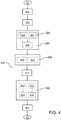
figure 4 shows, by means of a block diagram, a method for controlling a braking action applicable by a brake caliper on a mechanical movement member of a vehicle, according to an embodiment of the present invention; -
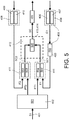
figure 5 shows, by means of a functional block chart, a method for controlling a braking action applicable by a brake caliper on a mechanical movement member of a vehicle, according to an embodiment, and -
figure 6 shows, by means of a functional block chart, a method for controlling a braking action applicable by a brake caliper on a mechanical movement member of a vehicle, according to a further embodiment. - A
system 100 for controlling a braking action applicable by a brake caliper on a mechanical movement member of a vehicle, hereinafter also control system or simply system, according to the present invention, will firstly be described with reference to the aforesaid figures. - It is worth noting that equal or similar elements in the figures will be indicated by the same reference numerals.
- It is worth noting that the vehicle, indicated by
reference numeral 200 as a whole, may be, for example, a car, a motorcycle, a light commercial vehicle, a heavy industrial vehicle or any other vehicle in which a braking action must be applied by actuating a brake caliper on mechanical movement members (e.g. rotors or aircraft landing gear). - With reference in particular to
figure 1 , thevehicle 200 comprises at least one mechanical movement member R1 (e.g. a wheel), a first brake disc DB1 operatively associated with said at least one mechanical movement member R1 and a first brake caliper PZ1 which can be actuated to apply on said first brake disc DB1, then on said at least one mechanical movement member R1, a braking action, e.g. a dissipative braking torque. - The
vehicle 200 further comprises thesystem 100 for controlling a braking action applicable by the brake caliper PZ1 on said at least one mechanical movement member R1. - The
system 100 further comprises anelectronic control unit 101 configured to execute a method for controlling the braking action applicable by a brake caliper PZ1 on a mechanical movement member R1 of avehicle 100. - Such control method will be described hereinafter according to one or more embodiments according to the present invention, with particular reference to
figures 4 ,5 and6 . - The
electronic control unit 101 may comprise one or more control modules or logics, e.g. microprocessors or microcontrollers, configured to execute the aforesaid control method as a whole. - Turning back to
figure 1 , thesystem 100 further comprises anactuator assembly 102 of said at least one brake caliper PZ1, operatively connected to theelectronic control unit 101. - It is worth noting that the
system 100, according to a further embodiment (not shown infigure 1 ), may comprise a further actuator assembly, entirely similar to theactuator assembly 102, of at least one second brake caliper (not shown in the figures), operatively connected to theelectronic control unit 101. - Indeed, the
vehicle 200 may comprise at least one further mechanical movement member (e.g. a further wheel, not shown infigure 1 ), a further brake disc (not shown in thefigure 1 ) operatively associated with said at least one mechanical movement member and the further first brake caliper which can be actuated to apply a braking action, e.g. a dissipative braking torque on said further brake disc, thus on said at least one further mechanical movement member R1. - The at least one mechanical movement member R1 and the at least one further mechanical movement member may belong to the same axis of the
vehicle 200, e.g. the front axle or the rear axle. - In such case, the respective actuator assemblies (the at least one
actuator assembly 102 and the further actuator assembly, respectively) are operatively connected to and controlled by theelectronic control unit 101 itself. - In general, the
system 100 may comprise a further actuator assembly, entirely similar to theactuator assembly 102, for each brake caliper with which thevehicle 200 may be provided. - Each brake caliper is operatively associated with a respective brake disc, on which to apply the braking action, operatively associated with a respective mechanical movement member, in turn.
- As previously mentioned, the actuator assemblies operatively connected to mechanical movement members belonging to the same vehicle axle (front or rear) are preferably controlled by the same electronic control unit.
- Turning back to the embodiment in
figure 1 and now making reference also the embodiments infigures 2 and3 , theactuator assembly 102 comprises at least oneelectric motor 103 and anactuator 104. - The
electric motor 103 is operatively connected to the electronic control unit 101 (not shown infigures 2 and3 ) to receive a respective control signal from it. - The
electric motor 103 is operatively connected to theactuator 104 by means of atransmission mechanism 105. - According to an embodiment, said
transmission mechanism 105 is of non-linear type. - "Transmission mechanism of non-linear type" means the set of one or more mechanisms having variable transmission ratio.
- An example of transmission mechanism of non-linear type is a rod-crack type mechanism.
- In a transmission mechanism of non-linear type, the translation speed of a translatable portion (e.g. the rod) is a non-linear function of the angular position of a rotatable portion (e.g. the crank) and also of the stroke of the translatable portion.
- The pressure of a fluid inside the braking system is approximately a linear function of the stroke of a piston (actuatable by the translatable portion of the non-linear transmission mechanism connected to the actuator 104) and the combination of such linear function with the non-linear function of the translation speed of the piston makes it possible to obtain a non-linear ratio between the torque of the
electric motor 103 and the stroke of the piston, in which, in a prevalent portion of the rear stretch (in the first half) of the stroke of the piston, the torque of theelectric motor 103 increases in approximately proportional (linear) manner with the advancement of the piston and, on the front stretch (in the second half) of the stroke of the piston, the torque of theelectric motor 103 increases in sub-proportional (or decreasing) manner or decreases with the advancement of the piston. - So, a transmission mechanism of non-linear type makes it possible to advantageously obtain an optimal operation of the
electric motor 103 and an accurate control of the fluid pressure in normal braking conditions (with the piston in the rear stretch of the stroke of the piston) and a very high pressurization of the fluid in exceptional braking conditions (with the piston in the front stretch of the stroke od the piston). - According to a further embodiment, alternative to the one above, the transmission mechanism may be of linear type.
- "Transmission mechanism of linear type" means the set of one or more mechanisms having fixed transmission ratio, e.g. a N:1 reduction ratio.
- An example of transmission mechanism of linear type is a cascade or planetary gear mechanism or a screw-nut screw mechanism.
- Turning back in general with
figures 1 ,2 and3 , theelectric motor 103 is configured to actuate theactuator 104 by means of thetransmission mechanism 105. - In an embodiment, shown in
figure 2 , theactuator assembly 102 is of the electro-hydraulic type. - In this embodiment, the
actuator 104 comprises one or more hydraulic cylinders. - The actuation by the
electric motor 103 of said one or more hydraulic cylinders generates inside the braking system the hydraulic pressure needed to move the brake caliper PZ1 in order to apply the braking action on the first brake disc D1, and thus on said at least one mechanical movement member R1. - In this embodiment, the
system 100 further comprises one or more sensors for detecting a parameter representative of a braking action applicable by the brake caliper PZ1 by means of theactuator assembly 102. - It is worth noting that for the purposes of the present description, "parameter representative of a braking action applicable by the brake caliper by means of the actuator assembly" means any physical quantity from which information representative of a braking action can be obtained, such as for example the force, the position, the pressure, the braking torque, the braking force on the ground, or any other combination thereof.
- So, said one or more sensors for detecting a parameter representative of the braking action applicable by the brake caliper PZ1 by means of the
actuator assembly 102 may be a force sensor, a pressure sensor, a position sensor, a braking torque sensor and so on. - Said one or more sensors for detecting a parameter representative of the braking action applicable by the brake caliper PZ1 by means of the
actuator assembly 102 are configured to provide a value of said at least one parameter detected in thesystem 100 to theelectronic control unit 101. - In an embodiment, shown by a broken line in
figure 2 , said one or more sensors for detecting a parameter representative of the braking action applicable by the brake caliper PZ1 by means of theactuator assembly 102, indicated byreference numeral 106, are inside theactuator assembly 102. - In particular, according to an embodiment, said one or more sensors for detecting a parameter representative of the braking action applicable by the brake caliper PZ1 by means of the
actuator assembly 102 arepressure sensors 106, operatively associated with one or more hydraulic cylinders of theactuator 104. - Each
pressure sensor 106 is configured to provide a pressure value to the electronic control unit detected inside the respective hydraulic cylinder. - According to a further embodiment, not shown in the figures, said one or more sensors for detecting a parameter representative of the braking action applicable by the brake caliper PZ1 by means of the
actuator assembly 102 are operatively associated with the first brake caliper PZ1. - According to a further embodiment, not shown in the figures, either alternatively or in combination with the one above, said one or more sensors for detecting a parameter representative of the braking action applicable by the brake caliper PZ1 by means of the
actuator assembly 102 are operatively associated with the first brake disc DB1. - According to a further embodiment, not shown in the figures, either alternatively or in combination with the ones above, said one or more sensors for detecting a parameter representative of the braking action applicable by the brake caliper PZ1 by means of the
actuator assembly 102 are operatively associated with at least one mechanical movement member R1. - In an embodiment, either alternatively or in combination with the ones above, the
system 100 further comprises one or more sensors (not shown in the figures) for detecting the position of a component in theactuator assembly 102. - In a further embodiment, also shown by broken lines in
figure 2 , theelectric motor 103 may be operatively connected to theactuator 104 also by means of afurther transmission mechanism 107 of linear type. - It is worth repeating that "transmission mechanism of linear type" means the set of one or more mechanisms having fixed transmission ratio, e.g. a N:1 reduction ratio.
- Examples of transmission mechanism of linear type are a cascade or planetary gear mechanism or a screw-nut screw type mechanism.
- It is worth noting that the
further transmission mechanism 107 is arranged in series with respect to thetransmission mechanism 105 between theelectric motor 103 and thetransmission mechanism 105. - It is worth noting that also if the
transmission mechanism 105 is of linear type, the further lineartype transmission mechanism 107 may be, for example, a cascade or planetary gear mechanism, while thetransmission mechanism 105 may be a screw-nut screw type mechanism. - With reference now to the embodiment shown in
figure 3 , alternative to the one shown with reference tofigure 2 , theactuator assembly 102 is of electro-mechanical type. - In this embodiment, the
actuator 104 comprises a piston mechanically connected to the brake caliper PZ1 (not shown infigure 2 ). - The actuation of the piston by the
electric motor 103 makes is possible to move the brake caliper PZ1 in order to apply the braking action of the first brake disc D1, and thus on said at least one first mechanical movement member R1. - In this embodiment, the
system 100 further comprises one or more sensors for detecting a parameter representative of a braking action applicable by the brake caliper PZ1 by means of theactuator assembly 102. - It is worth noting that for the purposes of the present description, "parameter representative of the braking action applicable by the brake caliper by means of the actuator assembly" means any physical quantity from which information representative of a braking action can be obtained, such as for example the force, the position, the pressure, the braking torque, the braking force on the ground, i.e. the force between the mechanical movement member and the surface on which the vehicle moves, or any other combination thereof.
- So, said one or more sensors for detecting a parameter representative of the braking action applicable by the brake caliper PZ1 by means of the
actuator assembly 102 could be a force sensor, a pressure sensor, a position sensor, a braking torque sensor, and so on. - Said one or more sensors for detecting a parameter representative of the braking action applicable by the brake caliper PZ1 by means of the
actuator assembly 102 are configured to provide a value of said at least one parameter detected in thesystem 100 to theelectronic control unit 101. - In an embodiment, shown by a broken line in
figure 3 , said one or more sensors for detecting a parameter representative of the braking action applicable by the brake caliper PZ1 by means of theactuator assembly 102, indicated byreference numeral 108, are inside theactuator assembly 102. - In particular, according to an embodiment, said one or more sensors for detecting a parameter representative of the braking action applicable by the brake caliper PZ1 by means of the
actuator assembly 102 are force sensors and/ortorque sensors 108 operatively associated with the piston 104 (actuator of the first brake caliper PZ1). - Each force sensor and/or
torque sensor 108 is configured to provide a force and/or torque value detected in thepiston 104 to the electronic control unit. - According to a further embodiment, not shown in the figures, said one or more sensors for detecting a parameter representative of the braking action applicable by the brake caliper PZ1 by means of the
actuator assembly 102 are operatively associated with the first brake caliper PZ1. - According to a further embodiment, not shown in the figures, either alternatively or in combination with the one above, said one or more sensors for detecting a parameter representative of the braking action applicable by the brake caliper PZ1 by means of the
actuator assembly 102 are operatively associated with the first brake disc DB1. - According to a further embodiment, not shown in the figures, either alternatively or in combination with the ones above, said one or more sensors for detecting parameter representative of the braking action applicable by the brake caliper PZ1 by means of the
actuator assembly 102 are operatively associated with at least one mechanical movement member R1. - In a further embodiment, also shown with broken lines in
figure 3 , theelectric motor 103 may be operatively connected to theactuator 104 also by means of a transmission mechanism of linear type 107 (fixed transmission ratio, e.g. with N:1 reduction ratio). - Examples of transmission mechanism of linear type are a cascade or planetary gear mechanism or a screw-nut screw type mechanism.
- It is worth noting that also in this embodiment, the
further transmission mechanism 107 is arranged in series with respect to thetransmission mechanism 105 between theelectric motor 103 and thetransmission mechanism 105. - It is worth noting that also if the
transmission mechanism 105 is of linear type, the further lineartype transmission mechanism 107 may be, for example, a cascade or planetary gear mechanism, while thetransmission mechanism 105 may be a screw-nut screw type mechanism. - With reference also to
figures 4 ,5 and6 , amethod 400 for controlling the braking action applicable by a brake caliper on a mechanical movement member of a vehicle is described, hereinafter control method or simply method. - As previously mentioned with reference to any one of the embodiments described above, the
actuator assembly 102 comprises at least oneelectric motor 103 and anactuator 104 of the brake caliper PZ1. - The
electric motor 103 is operatively connected to theactuator 104 by means of atransmission mechanism 105. - The
electric motor 103 is configured to actuate theactuator 104 by means of thetransmission mechanism 105. - Turning back to
figure 4 , themethod 400 comprises a symbolic step of starting ST. - The
method 400 further comprises a step of receiving 401, by anelectronic control unit 101 operatively connected to theactuator assembly 102, an input signal S1 representative of a braking request (also seefigure 5 and6 ). - In an embodiment, the braking request may be imparted by the driver of the vehicle by means of a brake pedal.
- According to a further embodiment, alternative to the one above, in the case of self-driving, emergency braking, anti-collision, the braking request may be provided automatically by the
vehicle 200 without any intervention by the driver of thevehicle 200. - In particular, the braking request may be provided by a further electronic control unit, a further control logic, a further hardware circuit, one or more sensors, and so on.
- Turning back to
figure 3 , themethod 400 further comprises a step of determining 402, by theelectronic control unit 101, on the basis of the received input signal: - a first reference value PT1 of a position of a component in the
actuator assembly 102; - a second reference value PT2 of a parameter representative of the braking action applicable by the brake caliper PZ1 by means of the
actuator assembly 102. - It is worth noting that the component in the
actuator assembly 102 may theactuator 104, i.e. one or more hydraulic cylinders if the actuator assembly is of the electro-hydraulic type, or a piston if the actuator assembly is of the electro-mechanical type, theelectric motor 103, one or more mechanical elements of transmission mechanism of linear type or of non-linear type. - It is worth noting that for the purposes of the present description, "parameter representative of the braking action applicable by the brake caliper PZ1 by means of the actuator assembly" means any physical quantity from which information representative of a braking action can be obtained, such as, for example, the force, the position, the pressure, the braking torque, the braking force on the ground, i.e. the force between the mechanical movement member and the surface on which the vehicle moves, or any other combination thereof.
- It is worth noting that step of determining 402 may be performed by an internal reference generation logic, indicated by 501 in
figures 5 and6 , belonging to theelectronic control unit 101. - The
method 400 further comprises a step of determining 403, by theelectronic control unit 101, a first feedback value F1 of the position of a component in theactuator assembly 102. - The step of determining 403 the first feedback value F1 of the position of a component in the
actuator assembly 102 comprises the steps of: - determining 404, by the
electronic control unit 101, a first current value C1 of the position of a component of theactuator assembly 102; - compensating 405, by the
electronic control unit 101, the effect of thetransmission mechanism 105 present in theactuator assembly 102 on the determined first current value C1 of the position of a component of theactuator assembly 102. - According to an example, the
transmission mechanism 105 may be of non-linear type, e.g. a rod-crank mechanism, the advantages of which were described above. - In this case, the first reference value PT1 of a position of a component inside the
actuator assembly 102 may be referred to the position of a component downstream of the transmission mechanism 105 (e.g. the rod-crank type mechanism), e.g. the position of thepiston 104, if theactuator assembly 102 is of the electro-mechanical type. - The first current value C1 of a position of a component of the
actuator assembly 102 may be instead referred to the position of a component upstream of the transmission mechanism 105 (e.g. the rod-crank type mechanism), e.g. the position of theelectric motor 103. - If the
transmission mechanism 105 is of non-linear type, and in particular is a rod-crank type mechanism, by combining appropriate mathematical ratios it is possible to determine the position X of the downstream component of the rod-crank mechanism (piston 104) on the basis of the measurement of the inclination angle of the crank, upstream of the rod-crank mechanism, or vice versa. - It is worth noting that the non-linear transmission mechanism also affects the non-constant reduction ratio between the force delivered downstream of the non-linear transmission mechanism and the braking torque generated upstream of the non-linear transmission mechanism.
- The compensation of the effect of the transmission mechanism may be performed by a control logic, indicated by
reference numeral 502 infigures 5 and6 , belonging to theelectronic control unit 101 and makes it possible to provide a first feedback value F1 of the position of a component in theactuator assembly 102 in any working point of the B-b-W (Brake-by-Wire) braking system in which thecontrol system 100, described above, is located. - It is worth noting that the step of compensating 405 makes it possible to make the measured position value and the respective position reference value homogeneous and take both downstream or upstream of the
transmission mechanism 105. - According to an embodiment, the step of determining 404 a first current value C1 of the position of a component of the
actuator assembly 102 comprises a step of measuring 406, by one or more position detection sensors with which thesystem 100 is provided, the position of the component in theactuator assembly 102. - In an embodiment, such one or more position detection sensors are arranged inside the
actuator assembly 102. - According to a further embodiment, either alternatively or in combination with the one above, the step of determining 404 a first current value C1 of the position of a component of the
actuator assembly 102 comprises a step of estimating 407, by the electronic control unit, the position of the component in theactuator assembly 102. - It is worth noting that this can be performed by starting from the measurement of electric current of the
electric motor 103, or exploiting the measurement of the electromotive force of theelectric motor 103, from which the speed is obtained, and by integrating the position, or by exploiting a dynamic model of theactuator assembly 102 from which the position of the component is obtained as output, given the same controls in electric voltage/electric current to theactuator 104 as inputs. - Turning back to the embodiment in
figure 4 , themethod 400 further comprises a step of determining 408, by theelectronic control unit 101, a second feedback value F2 of the parameter representative of the braking action applicable by the brake caliper PZ1 by means of theactuator assembly 102. - In an embodiment, the step of determining 408 the second feedback value F2 of the parameter representative of the braking action applicable by the brake caliper PZ1 by means of the
actuator assembly 102 comprises a step of measuring 409, by means of one or more sensors with which thesystem 100 is provided, the parameter representative of the braking action applicable by the brake caliper PZ1 by means of theactuator assembly 102. - Examples of type and arrangement in the
system 100 of said one or more sensors were described above with reference to the description of the different embodiments of thesystem 100. - According to a further embodiment, either alternatively or in combination with the one above, the step of determining 408 the second feedback value F2 of the parameter representative of the braking action applicable by the brake caliper PZ1 by means of the
actuator assembly 102 comprises a step of estimating 410, by theelectronic control unit 101, the parameter representative of the braking action applicable by the brake caliper PZ1 by means of theactuator assembly 102. - The estimate may be performed, for example:
- starting from the electric current of the
electric motor 103 and, by means of a dynamic model of theactuator 104, by calculating the braking torque of theelectric motor 103, and thus the braking force; - starting from the deceleration of the
vehicle 200 and the slip of said at least one mechanical movement member (wheel), and by means of the model of thevehicle 200, tracing back to the braking force on the ground, and thus to the braking torque and finally to the braking force; - using the position measurement and based on the position-nominal force relationship, with the due compensations related to temperature, aging, wear and so on.
- Turning back to the embodiment in
figure 3 , themethod 400 further comprises a step of generating 411, by the electronic control unit 101: - a first intermediate control signal SC1 of the
actuator assembly 102 on the basis of the comparison between the first feedback value F1 of the position of a component in theactuator assembly 102 and the first reference value PT1 of the position of a component in theactuator assembly 102; - a second intermediate control signal SC2 of the
actuator assembly 102 on the basis of the comparison of the second feedback value F2 of the parameter representative of the braking action applicable by the brake caliper PZ1 by means of theactuator assembly 102 and the second reference value PT2 of the parameter representative of the braking action applicable by the brake caliper PZ1 by means of theactuator assembly 102. - It is worth noting that step of generating the first intermediate control value SC1 of the
actuator assembly 102 and the second intermediate control value SC2 of theactuator assembly 102 is performed by respective control logics, indicated respectively by thereference numerals 503, 503' for the first intermediate control signal SC1 and with thereference numerals 504, 504' for the second intermediate control signal SC2, belonging to theelectronic control unit 101. - It is worth noting that the step of generating the first intermediate control value SC1 of the
actuator assembly 102 is possible by virtue of the step of compensating, which makes it possible to make the measured position value and the respective position reference value homogeneous and take both downstream or upstream of thetransmission mechanism 105. - The
method 400 further comprises a step of generating 412, by theelectronic control unit 101, a control signal SC of theactuator assembly 102 on the basis of the first intermediate control signal SC1 of theactuator assembly 102 and of the second intermediate control signal SC2 of theactuator assembly 102. - In an embodiment with a single control loop, shown in
figure 5 , the first intermediate control signal SC1 and the second intermediate control signal SC2 are a first error signal SC1 and a second error signal SC2, respectively. - The first error signal SC1 can be obtained instant-by-instant by subtracting the first reference value PT1 of the position of a component in the
actuator assembly 102 from the first feedback value F1 of the position of a component in the actuator assembly 102 (SC1 = F1 - PT1). - The second intermediate control signal SC2 can be obtained instant-by-instant by subtracting the second reference value PT2 of the parameter representative of the braking action applicable by the brake caliper PZ1 by means of the
actuator assembly 102 from the second feedback value F2 of the parameter representative of the braking action applicable by the brake caliper PZ1 by means of the actuator assembly 102 (SC2 = F2 - PT2). - The step of generating 412 comprises the steps of:
- selecting 413, by the
electronic control unit 101, one of or a combination of said first error signal SC1 and said second error signal CS2; - determining 414, by the
electronic control unit 101, the control signal SC of theactuator assembly 102 on the basis of said one of the first error signal SC1 and the second error signal SC2; - It is worth noting that control signal SC of the
actuator assembly 102 is the output of a controller (indicated byreference numeral 505 infigure 5 and byreference numeral 507 infigure 6 ), which may be a PI or PID controller or an optimal control, for example. - The step of selecting 413 is based on multiple conditions and depends on various signals which may be either present or not, such as: the value of the input signal S1, derivate of the input signal S1, measured force, measured position, force reference, position reference, time elapsed since the beginning of the braking request, output signal level (output from block 103' in
figures 5 and6 ), internal system state. - The selection may be a simple passage of the first error signal SC1 to the second error signal SC2 and vice versa, and may be instantaneous (either said first error or said second error signal is used in one step and the other one is used in the successive step), or may be a linear combination between the first error signal SC1 and the second error signal SC2 to make a gradual/smooth passage in several steps, according to the following formula:

- It is worth noting that the step of generating 412, in the embodiment in
figure 5 , is performed by a control or arbitration logic, indicated byreference numeral 505, belonging to the electronic control unit. - In an embodiment with multiple control loops, shown in
figure 6 , the first intermediate control signal SC1 and the second intermediate control signal SC2 are respectively a first speed value SC1 and a second speed value SC2 coming from the control of the parameter representative of the braking action of theactuator assembly 102 and the control of the position of the component in theactuator assembly 102. - In greater detail, in the embodiment of
figure 6 , a controller 504 (P or PI), adapted to generate a speed reference value, is used in the step of calculating the first error signal SC1 (SC1 = FI - PTI). - Furthermore, a feed-forward component 504' may be optionally used, in parallel to the
controller 504, which generates a speed reference signal which is added to the output of theregulator 504 by using the first reference value PT1 only as input. - In entirely similar manner, in the embodiment in
figure 6 , a further controller 503 (P or PI), adapted to generate a further speed reference value, is used in the step of calculating the second error signal SC2 (SC2 = FI - PTI). - Furthermore, a further feed-forward component 503' may be optionally used, in parallel to the
further controller 503, which generates a further speed reference signal which is added to the output of theregulator 503 by using the second reference value PT2 as input only. - It is worth noting that the
controller 504, the feed-forward component 504', thefurther regulator 503 and the further feed-forward component 504' are part of theelectronic control unit 101. - Turning back to the embodiment in
figure 4 , the step of generating 412 comprises the steps of: - selecting 415, by the
electronic control unit 101, either one or a combination of said first speed value SC1 and said second speed value CS2; - determining 416, by the
electronic control unit 101, the control signal SC of theactuator assembly 102 on the basis of the comparison between said one of said first speed value SC1 and the second speed value SC2 and a speed feedback value VF of theelectric motor 103 of theactuator assembly 102. - The speed feedback value VF may be determined starting from the position of the
electric motor 103, or by means of a speed sensor positioned on theelectric motor 103, or by a speed estimator, also belonging to theelectronic control unit 101. - It is worth noting that the step of selecting 415 occurs according to a complex logic entirely similar to that described above with reference to the step of selecting 213.
- Furthermore, in greater detail, it is worth noting that in the step of determining 416 the error is calculated between the reference signal output from the step of selecting 415 and successively, by using a further PI or PID controller, the control signal SC is generated.
- It is worth noting that the step of generating 412, in the embodiment in
figure 5 , is performed by a control or arbitration logic, indicated byreference numeral 505, belonging to the electronic control unit. - It is worth noting that the step of selecting 415 and the step of determining 416 are performed by respective control logics, indicated by
reference numerals electronic control unit 101, respectively. - Turning back to the embodiment in
figure 4 , themethod 400 further comprises a step of providing 417 to theelectric motor 103 of theactuator assembly 102, by theelectronic control unit 101, the generated control signal SC. - With this regard, both in the embodiment shown in
figure 5 (single control loop) and in the embodiment infigure 6 (multiple control loops), the generated control signal SC may be a digital modulation signal of the PWM type, standing for Pulse Width Modulation, an electrical voltage analog signal or an electric current analog signal. - It is worth noting that the control signal SC is provided with a driving module 103' of the
electric motor 103. - Turning back to the embodiment in
figure 4 , themethod 400 comprises a symbolic step of ending ED. - The
method 400 is cyclic so the steps described from step of starting ST to the step of ending ED are run cyclically whenever themethod 400 is run. - In a further embodiment, not shown in the figures, either alternatively or in combination with any one of the embodiments described above, the
method 400 further comprises a step of adapting, by theelectronic control unit 101, control parameters, such as for example the position of the component in theactuator assembly 102 and the parameter representative of the braking action applicable by the brake caliper PZ1 by means of theactuator assembly 102, on the basis of stiffness variations of the brake caliper PZ1. - It is worth noting that the step of adapting may be envisaged in optimization perspective of the control system performance according to the working point of the brake caliper.
- In greater detail, the step of adapting comprises the step of identifying, by the
electronic control unit 101, starting from a set of reference values of the position of the component in theactuator assembly 102 and of the parameter representative of the braking action applicable by the brake caliper PZ1 by means of theactuator assembly 102, a variation of stiffness of the brake caliper PZ1 by comparing a current stiffness value of the brake caliper PZ1 (determined by means of the use of force sensors positioned at the brake caliper PZ1 or estimated indirectly by other quantities) with a nominal stiffness value of the brake caliper PZ1. - It is worth noting that the control parameters can be modified by the
electronic control unit 101 continuously by a quantity obtained as a function of the entity of the variation of the current rigidity curve with respect to the nominal rigidity curve by means of an either linear or non-linear law and may keep in consideration also the non-linearity of the transmission mechanism of non-linear type. - Furthermore, other control parameters may be modified by the electronic control unit in discreet manner when the different thresholds of the current rigidity curve with respect to the nominal rigidity curve are exceeded.
- It is worth noting that the updating frequency of the control parameters may be different according to embodiments.
- For example, control parameters may be updated by the
electronic control unit 101 as a function of the number of key cycles, as a function of the number of braking operations. - Furthermore, the updating may be performed by the
electronic control unit 101 according to the time or to the kilometers traveled by the vehicle or as a function of variations of temperature of the intensity of use of the brakes in a set period of time. - It is worth noting that the possible variations of the
control system 100 include the wear of the pads on which the brake caliper PZ1 acts, which modify the curve representing system rigidity. - With this regard, an estimate of the wear of the brake pad makes it possible to adapt the respective control parameters so as to always have a system response coherent to the state of the latter.
- According to an embodiment, the nominal rigidity of the brake caliper PZ1 may be identified by an initialization procedure of the
control system 100 which makes it possible to reconstitute the nominal rigid curve of the brake caliper PZ1 starting from come characteristic points of the system sufficient to cover the entire operative range. - Once the nominal rigidity curve of the brake caliper PZ1 has been identified, the
method 400, in an embodiment, may collocate thecontrol system 100 in a family of brake calipers using a predetermined set of reference (default) parameters for control. - It is worth noting that the step of adapting the control parameters described above can be used to adapt the control parameters starting from the selected set of reference (default) control parameters and optimizing them for the brake caliper connected to the
control system 100. - In this manner it is possible to advantageously obtain a self-calibration of the
control system 100 which makes it possible to maximize performance by adapting the control parameter to the brake caliper type and the rigidity variations of the connecting brake caliper. - The
control method 400 and thecontrol system 100 according to the present invention have many advantages. - The
method 400, by taking into consideration the variable transmission radio in the various working position, can adapt the control parameters in order to maximize performance, while maintaining a high level of robustness so as to work correctly regardless of the system variations due to temperature, wear, aging and so forth. - The
control method 400 may be performed by an electro-hydraulic or electro-mechanical actuator assembly using a Brake-by-Wire braking system, by managing a transmission mechanism of non-linear type so as to provide good performance in all working points of the actuator assembly, adapting to the current conditions of the actuator assembly, whereby compensating wear, aging, temperature and so on, modify the control parameters to optimize the performance of the B-b-W type braking system. - Another important advantage of the
method 400 is the possibility of being used both on transmission mechanisms of non-linear type and on transmission mechanisms of linear type. - The
control method 400 may be calibrated and configured to obtain optimal results (in case of non-linear type and linear type transmissions) for different applications according to the brake calipers and of the vehicle on which the control method is used. - The
control method 400 may be calibrated to be used for each electro-hydraulic or electro-mechanical actuator assembly - brake caliper to have the best response for the overall Brake-by-Wire type braking system. - The linear component of the transmission mechanism can be assessed in the first part of the braking request, while the behavior of the non-linear component of the transmission mechanism may be assessed when the actuator is pushed nearly to its limit or in extreme and particular conditions, such as fading or degraded conditions.
- The
control method 400 and the system thereof may be used in presence of transmission mechanisms of non-linear type and in the case of transmission mechanisms of linear type, since the linear transmission is a particular case of non-linear transmission. - Furthermore, the
method 400 may show an adaptation function of the parameters which make it possible to vary the value of the control parameters in order to optimize performance adapting to variations of the system under control. - A person skilled in art may make changes and adaptations to the method and system thereof described above without departing from the scope of protection of the appended claims.
Claims (15)
- A method (400) for controlling the braking action applicable by a brake caliper (PZ1) on a mechanical movement member (R1) of a vehicle (200), said brake caliper (PZ1) being actuatable by an actuator assembly (102) comprising at least one electric motor (103) and an actuator (104) of the brake caliper (PZ1), the electric motor (103) being operatively connected to the actuator (104) by means of a transmission mechanism (105), the electric motor (103) being configured to operate the actuator (104) by means of the transmission mechanism (105), the method (400) comprising steps of:- receiving (401), by an electronic control unit (101) operatively connected to the actuator assembly (102), an input signal (S1) representative of a braking request;- determining (402), by the electronic control unit (101), on the basis of the received input signal (S1):- a first reference value (PT1) of a position of a component in the actuator assembly (102);- a second reference value (PT2) of a parameter representative of the braking action operable by the brake caliper (PZ1) by means of the actuator assembly (102);- determining (403), by the electronic control unit (101), a first feedback value (F1) of the position of a component in the actuator assembly (102);- determining (408), by the electronic control unit (101), a second feedback value (F2) of the parameter representative of the braking action applicable by the brake caliper (PZ1) by means of the actuator assembly (102);- generating (411), by the electronic control unit (101):- a first intermediate control signal (SC1) of the actuator assembly (102) on the basis of the comparison between the first feedback value (F1) of the position of a component in the actuator assembly (102) and the first reference value (PT1) of the position of a component in the actuator assembly (102);- a second intermediate control signal (SC2) of the actuator assembly (102) on the basis of the comparison of the second feedback value (F2) of the parameter representative of the braking action applicable by the brake caliper (PZ1) by means of the actuator assembly (102) and the second reference value (PT2) of the parameter representative of the braking action applicable by the brake caliper (PZ1) by means of the actuator assembly (102);- generating (412), by the electronic control unit (101), a control signal (SC) of the actuator assembly (102) on the basis of the first intermediate control signal (SC1) of the actuator assembly (102) and of the second intermediate control signal (SC2) of the actuator assembly (102), the step of generating comprising a step of selecting, by the electronic control unit (101), one of or a combination of said first intermediate control signal (SC1) and said second intermediate control signal (SC2), the step of selecting being performed on the basis of the comparison between said first intermediate control signal (SC1) and said second intermediate control signal (SC2);- providing (417) to the electric motor (103) of the actuator assembly (102), by the electronic control unit (101), the generated control signal (SC).
- A method (400) according to claim 1, wherein the step of determining (403) the first feedback value (F1) of the position of a component in the actuator assembly (102) comprises the steps of:- determining (404), by the electronic control unit (101), a first current value (C1) of the position of a component of the actuator assembly (102);- compensating (405), by the electronic control unit (101), the effect of the transmission mechanism (105) present in the actuator assembly (102) on the determined first current value (C1) of the position of a component of the actuator assembly (102).
- A method (400) according to claim 2, wherein the step of determining (404) a first current value (C1) of the position of a component of the actuator assembly (102) comprises a step of measuring (406), by one or more position detection sensors, the position of the component in the actuator assembly (102).
- A method (400) according to any one of the claims 2 and 3, wherein the step of determining (404) a first current value (C1) of the position of a component of the actuator assembly (102) comprises a step of estimating (407), by the electronic control unit (101), the position of the component in the actuator assembly (102).
- A method (400) according to any one of the preceding claims, wherein the step of determining (408) the second feedback value (F2) of the parameter representative of the braking action applicable by the brake caliper (PZ1) by means of the actuator assembly (102) comprises a step of measuring (409), by one or more actuators, the parameter representative of the braking action applicable by the brake caliper (PZ1) by means of the actuator assembly (102).
- A method (400) according to any one of the preceding claims, wherein the step of determining (408) the second feedback value (F2) of the parameter representative of the braking action applicable by the brake caliper (PZ1) by means of the actuator assembly (102) comprises a step of estimating (410), by the electronic control unit (101), the parameter representative of the braking action applicable by the brake caliper (PZ1) by means of the actuator assembly (102).
- A method (400) according to any one of the preceding claims, wherein the first intermediate control signal (SC1) and the second intermediate control signal (SC2) are respectively a first error signal (SC1) and a second error signal (SC2), the step of generating (412) comprising the steps of:- selecting (413), by the electronic control unit (101), one of or a combination of said first error signal (SC1) and said second error signal (SC2);- determining (414), by the electronic control unit (101), the control signal (SC) of the actuator assembly (102) on the basis of said one of the first error signal (SC1) and the second error signal (SC2);
- A method (400) according to any one of the preceding claims from 1 to 6, wherein the first intermediate control signal (SC1) and the second intermediate control signal (SC2) are respectively a first speed value (SC1) and a second speed value (SC2) coming from the control of the parameter representative of the braking action of the actuator assembly (102) and the control of the position of the component in the actuator assembly (102), the step of generating (412) comprising the steps of:- selecting (415), by the electronic control unit (101), one of or a combination of said first speed value (SC1) and said second speed value (SC2);- determining (416), by the electronic control unit (101), the control signal (SC) of the actuator assembly (102) on the basis of the comparison between said one of said first speed value (SC1) and the second speed value (SC2) and a speed feedback value (VF) of the electric motor (103) of the actuator assembly (102).
- A method (400) according to any one of the preceding claims, further comprising a step of adapting, by the electronic control unit (101), the position of the component in the actuator assembly (102) and the parameter representative of the braking action applicable by the brake caliper (PZ1) by means the actuator assembly (102) on the basis of stiffness variations of the brake caliper (PZ1), the step of adapting comprising a step of identifying, by the electronic control unit (101), a variation of stiffness of the brake caliper (PZ1) by comparing a current stiffness value of the brake caliper (PZ1) with a nominal stiffness value of the brake caliper (PZ1), starting from a set of reference values of the position of the component in the actuator assembly (102) and of the parameter representative of the braking action applicable by the brake caliper (PZ1) by means of the actuator assembly (102).
- A system (100) for controlling a braking action applicable by a brake caliper (PZ1) on a mechanical movement member (R1) of a vehicle (200), comprising:- an electronic control unit (101) configured to execute a method (400) for controlling the braking action applicable by a brake caliper (PZ1) on a mechanical movement member (R1) of a vehicle (100) according to any one of the preceding claims;- an actuator assembly (102) of said at least one brake caliper (PZ1), operatively connected to the electronic control unit (101),
the actuator assembly (102) comprising at least one electrical motor (103) and one actuator (104), the electrical motor (103) being operatively connected to the electronic control unit (101) to receive a respective control signal (SC) from it, the electric motor (103) being operatively connected to the actuator (104) by means of a transmission mechanism (105), the electric motor (103) being configured to operate the actuator (104) by means of the transmission mechanism (105). - A system (100) according to claim 10, wherein the actuator assembly (102) is of the electro-hydraulic type, the actuator (104) comprising one or more hydraulic cylinders, the system (100) comprising one or more pressure sensors (106) operatively associated with one or more hydraulic cylinders of the actuator (104), the electrical motor (103) being operatively connected to the actuator (104) by means of a further transmission mechanism (107) of linear type, the further transmission mechanism (107) of linear type being arranged in series to the transmission mechanism (105) between the electric motor (103) and the transmission mechanism (105).
- A system (100) according to claim 10, wherein the actuator assembly (102) is of the electro-mechanical type, the actuator (104) comprising a piston mechanically connected to the brake caliper (PZ1), the system (100) comprising one or more force sensors and/or one or more torque sensors (108) operatively associated with the piston (104), the electric motor (103) being operatively connected to the actuator (104) also by means of a further transmission mechanism (107) of linear type, the further transmission mechanism (107) of linear type being arranged in series to the transmission mechanism (105) between the electric motor (103) and the transmission mechanism (105).
- A system (100) according to any one of the preceding claims from 10 to 12, further comprising one or more sensors for detecting the position of a component in the actuator assembly (102).
- A system (100) according to any one of the preceding claims from 10 to 13, wherein the transmission mechanism (105) is of the non-linear type.
- A system (100) according to any one of the preceding claims from 10 to 13, wherein the transmission mechanism (105) is of the linear type.
Applications Claiming Priority (2)
| Application Number | Priority Date | Filing Date | Title |
|---|---|---|---|
| IT102016000131985A IT201600131985A1 (en) | 2016-12-29 | 2016-12-29 | Method of controlling a braking action that can be exercised by a brake caliper on a mechanical movement organ of a vehicle and its control system. |
| PCT/IB2017/058432 WO2018122741A1 (en) | 2016-12-29 | 2017-12-27 | Method for controlling a braking action applicable by a brake caliper on a mechanical movement member of a vehicle and system thereof |
Publications (2)
| Publication Number | Publication Date |
|---|---|
| EP3562722A1 EP3562722A1 (en) | 2019-11-06 |
| EP3562722B1 true EP3562722B1 (en) | 2021-12-22 |
Family
ID=58671755
Family Applications (1)
| Application Number | Title | Priority Date | Filing Date |
|---|---|---|---|
| EP17832572.6A Active EP3562722B1 (en) | 2016-12-29 | 2017-12-27 | Method for controlling a braking action applicable by a brake caliper on a mechanical movement member of a vehicle and system thereof |
Country Status (6)
| Country | Link |
|---|---|
| US (1) | US11643059B2 (en) |
| EP (1) | EP3562722B1 (en) |
| CN (1) | CN110167805B (en) |
| ES (1) | ES2909051T3 (en) |
| IT (1) | IT201600131985A1 (en) |
| WO (1) | WO2018122741A1 (en) |
Families Citing this family (2)
| Publication number | Priority date | Publication date | Assignee | Title |
|---|---|---|---|---|
| US12559083B2 (en) | 2023-05-31 | 2026-02-24 | Ford Global Technologies, Llc | Control system for individual actuation of brake caliper pistons |
| IT202400000552A1 (en) | 2024-01-15 | 2025-07-15 | Brembo Spa | “METHOD OF CONTROLLING THE ACTUATION OF A BRAKING SYSTEM USING PREDICTIVE CONTROL TECHNIQUES AND RELATED BRAKING SYSTEM” |
Family Cites Families (16)
| Publication number | Priority date | Publication date | Assignee | Title |
|---|---|---|---|---|
| DE19536694A1 (en) * | 1995-09-30 | 1997-04-03 | Teves Gmbh Alfred | Control system for an electromotive wheel brake |
| DE19730094A1 (en) * | 1997-07-14 | 1999-01-21 | Itt Mfg Enterprises Inc | System for controlling or regulating an electromechanical brake |
| KR100567637B1 (en) * | 1997-11-22 | 2006-04-05 | 콘티넨탈 테베스 아게 운트 코. 오하게 | Method and system of operation of mechanical and electric parking brake for automobile |
| DE102005011267A1 (en) * | 2004-04-17 | 2006-03-30 | Continental Teves Ag & Co. Ohg | Method and control system for applying defined clamping forces |
| DE602005019563D1 (en) * | 2004-06-04 | 2010-04-08 | Goodrich Corp | MEASUREMENT AND CONTROL OF POSITION AND POWER IN ELECTRIC BRAKES |
| FR2882541B1 (en) * | 2005-02-25 | 2009-01-16 | Messier Bugatti Sa | ASSEMBLY METHOD IN AN ELECTRIC BRAKE VEHICLE BRAKING SYSTEM |
| US20070235267A1 (en) * | 2006-04-11 | 2007-10-11 | Goodrich Corporation | Controller for electromechanical braking system with running clearance adjustment and method |
| US8590985B2 (en) * | 2008-09-30 | 2013-11-26 | Goodrich Corporation | Method to degrade braking modes |
| US8689301B2 (en) | 2008-09-30 | 2014-04-01 | Avaya Inc. | SIP signaling without constant re-authentication |
| DE102010038306A1 (en) * | 2010-06-15 | 2011-12-15 | Continental Teves Ag & Co. Ohg | Method and device for controlling an electrically actuated brake and electronic brake system |
| JP5320380B2 (en) * | 2010-12-20 | 2013-10-23 | 本田技研工業株式会社 | Brake device for vehicle |
| DE112014001471B4 (en) * | 2013-03-15 | 2022-02-17 | Advics Co., Ltd. | Electrical braking system for a vehicle |
| CN105050873B (en) * | 2013-03-15 | 2017-07-25 | 株式会社爱德克斯 | The electrical braking device of vehicle |
| JP6248588B2 (en) * | 2013-12-05 | 2017-12-20 | 株式会社アドヴィックス | Electric braking device for vehicle |
| US9506826B2 (en) * | 2014-12-09 | 2016-11-29 | Goodrich Corporation | Open loop load force estimation systems and methods |
| US9783171B2 (en) * | 2015-07-02 | 2017-10-10 | Goodrich Corporation | Electromechanical braking systems and methods with power demand control |
-
2016
- 2016-12-29 IT IT102016000131985A patent/IT201600131985A1/en unknown
-
2017
- 2017-12-27 US US16/474,085 patent/US11643059B2/en active Active
- 2017-12-27 WO PCT/IB2017/058432 patent/WO2018122741A1/en not_active Ceased
- 2017-12-27 CN CN201780081642.0A patent/CN110167805B/en active Active
- 2017-12-27 ES ES17832572T patent/ES2909051T3/en active Active
- 2017-12-27 EP EP17832572.6A patent/EP3562722B1/en active Active
Also Published As
| Publication number | Publication date |
|---|---|
| EP3562722A1 (en) | 2019-11-06 |
| US11643059B2 (en) | 2023-05-09 |
| WO2018122741A1 (en) | 2018-07-05 |
| US20200122695A1 (en) | 2020-04-23 |
| CN110167805A (en) | 2019-08-23 |
| ES2909051T3 (en) | 2022-05-05 |
| CN110167805B (en) | 2022-10-11 |
| IT201600131985A1 (en) | 2018-06-29 |
Similar Documents
| Publication | Publication Date | Title |
|---|---|---|
| US8768552B2 (en) | Vehicle brake system and method of operating the same | |
| US11448275B2 (en) | Technique for operating a vehicle brake having a hydraulic service brake and an electric parking brake | |
| US9643583B2 (en) | Method for providing the clamping force generated by a parking brake | |
| US8676409B2 (en) | Electric brake apparatus | |
| US20150151727A1 (en) | Braking control device for vehicle | |
| US11458945B2 (en) | Electromechanical brake system | |
| US9759626B2 (en) | System and method to adjust a force zero reference | |
| US20130211684A1 (en) | Method, regulating and control appliance, and parking brake comprising such a regulating and control appliance, for adjusting a clamping force exerted by a parking brake | |
| US9511752B2 (en) | Method for operating a brake system, and brake system | |
| KR20100090694A (en) | Parking brake and method for operating the same | |
| CN105050871A (en) | Electric braking device for vehicle | |
| EP3562722B1 (en) | Method for controlling a braking action applicable by a brake caliper on a mechanical movement member of a vehicle and system thereof | |
| KR20230158845A (en) | Electro-Mechanical Brake And Control Method Thereof | |
| IT202100024236A1 (en) | METHOD AND SYSTEM OF CONTROL OF A BRAKING SYSTEM | |
| US11565671B2 (en) | Method for monitoring an electric motor, electronic control module, hydraulic brake system and storage medium | |
| KR101609900B1 (en) | Braking system having parking brake integration | |
| JP2020093721A (en) | Electric brake apparatus | |
| US20190299954A1 (en) | Method for estimating the coefficient of friction of a hydraulic brake system | |
| KR102418890B1 (en) | Control device and method for operating an electromechanical brake booster of a brake system of a vehicle | |
| US7374254B2 (en) | Electric caliper position control with adaptive estimation | |
| CN102371987B (en) | Efficiency measuring method of electrically operated parking brake in motor vehicle | |
| WO2023243266A1 (en) | Electric brake device | |
| EP2371586A1 (en) | Method for controlling the fluidic actuation of a brake or suspension system | |
| EP1826081B1 (en) | Method of boosting a motor torque command based on transient position error signal | |
| CN120697717B (en) | Brake control method and system of vehicle-mounted stay wire motor |
Legal Events
| Date | Code | Title | Description |
|---|---|---|---|
| STAA | Information on the status of an ep patent application or granted ep patent |
Free format text: STATUS: UNKNOWN |
|
| STAA | Information on the status of an ep patent application or granted ep patent |
Free format text: STATUS: THE INTERNATIONAL PUBLICATION HAS BEEN MADE |
|
| PUAI | Public reference made under article 153(3) epc to a published international application that has entered the european phase |
Free format text: ORIGINAL CODE: 0009012 |
|
| STAA | Information on the status of an ep patent application or granted ep patent |
Free format text: STATUS: REQUEST FOR EXAMINATION WAS MADE |
|
| 17P | Request for examination filed |
Effective date: 20190613 |
|
| AK | Designated contracting states |
Kind code of ref document: A1 Designated state(s): AL AT BE BG CH CY CZ DE DK EE ES FI FR GB GR HR HU IE IS IT LI LT LU LV MC MK MT NL NO PL PT RO RS SE SI SK SM TR |
|
| AX | Request for extension of the european patent |
Extension state: BA ME |
|
| DAV | Request for validation of the european patent (deleted) | ||
| DAX | Request for extension of the european patent (deleted) | ||
| RAP3 | Party data changed (applicant data changed or rights of an application transferred) |
Owner name: BREMBO S.P.A. |
|
| RIN1 | Information on inventor provided before grant (corrected) |
Inventor name: PAOLINI, DAVIDE Inventor name: FORNI, FABRIZIO Inventor name: UGOLINI, LUCA Inventor name: ROSSI, ALESSANDRO |
|
| RAP3 | Party data changed (applicant data changed or rights of an application transferred) |
Owner name: BREMBO S.P.A. |
|
| GRAP | Despatch of communication of intention to grant a patent |
Free format text: ORIGINAL CODE: EPIDOSNIGR1 |
|
| STAA | Information on the status of an ep patent application or granted ep patent |
Free format text: STATUS: GRANT OF PATENT IS INTENDED |
|
| INTG | Intention to grant announced |
Effective date: 20210824 |
|
| RIN1 | Information on inventor provided before grant (corrected) |
Inventor name: PAOLINI, DAVIDE Inventor name: FORNI, FABRIZIO Inventor name: UGOLINI, LUCA Inventor name: ROSSI, ALESSANDRO |
|
| GRAS | Grant fee paid |
Free format text: ORIGINAL CODE: EPIDOSNIGR3 |
|
| GRAA | (expected) grant |
Free format text: ORIGINAL CODE: 0009210 |
|
| STAA | Information on the status of an ep patent application or granted ep patent |
Free format text: STATUS: THE PATENT HAS BEEN GRANTED |
|
| AK | Designated contracting states |
Kind code of ref document: B1 Designated state(s): AL AT BE BG CH CY CZ DE DK EE ES FI FR GB GR HR HU IE IS IT LI LT LU LV MC MK MT NL NO PL PT RO RS SE SI SK SM TR |
|
| REG | Reference to a national code |
Ref country code: GB Ref legal event code: FG4D |
|
| REG | Reference to a national code |
Ref country code: CH Ref legal event code: EP |
|
| REG | Reference to a national code |
Ref country code: DE Ref legal event code: R096 Ref document number: 602017051354 Country of ref document: DE |
|
| REG | Reference to a national code |
Ref country code: AT Ref legal event code: REF Ref document number: 1456873 Country of ref document: AT Kind code of ref document: T Effective date: 20220115 |
|
| REG | Reference to a national code |
Ref country code: IE Ref legal event code: FG4D |
|
| REG | Reference to a national code |
Ref country code: LT Ref legal event code: MG9D |
|
| PG25 | Lapsed in a contracting state [announced via postgrant information from national office to epo] |
Ref country code: RS Free format text: LAPSE BECAUSE OF FAILURE TO SUBMIT A TRANSLATION OF THE DESCRIPTION OR TO PAY THE FEE WITHIN THE PRESCRIBED TIME-LIMIT Effective date: 20211222 Ref country code: LT Free format text: LAPSE BECAUSE OF FAILURE TO SUBMIT A TRANSLATION OF THE DESCRIPTION OR TO PAY THE FEE WITHIN THE PRESCRIBED TIME-LIMIT Effective date: 20211222 Ref country code: FI Free format text: LAPSE BECAUSE OF FAILURE TO SUBMIT A TRANSLATION OF THE DESCRIPTION OR TO PAY THE FEE WITHIN THE PRESCRIBED TIME-LIMIT Effective date: 20211222 Ref country code: BG Free format text: LAPSE BECAUSE OF FAILURE TO SUBMIT A TRANSLATION OF THE DESCRIPTION OR TO PAY THE FEE WITHIN THE PRESCRIBED TIME-LIMIT Effective date: 20220322 |
|
| REG | Reference to a national code |
Ref country code: NL Ref legal event code: MP Effective date: 20211222 |
|
| REG | Reference to a national code |
Ref country code: ES Ref legal event code: FG2A Ref document number: 2909051 Country of ref document: ES Kind code of ref document: T3 Effective date: 20220505 |
|
| REG | Reference to a national code |
Ref country code: AT Ref legal event code: MK05 Ref document number: 1456873 Country of ref document: AT Kind code of ref document: T Effective date: 20211222 |
|
| PG25 | Lapsed in a contracting state [announced via postgrant information from national office to epo] |
Ref country code: SE Free format text: LAPSE BECAUSE OF FAILURE TO SUBMIT A TRANSLATION OF THE DESCRIPTION OR TO PAY THE FEE WITHIN THE PRESCRIBED TIME-LIMIT Effective date: 20211222 Ref country code: NO Free format text: LAPSE BECAUSE OF FAILURE TO SUBMIT A TRANSLATION OF THE DESCRIPTION OR TO PAY THE FEE WITHIN THE PRESCRIBED TIME-LIMIT Effective date: 20220322 Ref country code: LV Free format text: LAPSE BECAUSE OF FAILURE TO SUBMIT A TRANSLATION OF THE DESCRIPTION OR TO PAY THE FEE WITHIN THE PRESCRIBED TIME-LIMIT Effective date: 20211222 Ref country code: HR Free format text: LAPSE BECAUSE OF FAILURE TO SUBMIT A TRANSLATION OF THE DESCRIPTION OR TO PAY THE FEE WITHIN THE PRESCRIBED TIME-LIMIT Effective date: 20211222 Ref country code: GR Free format text: LAPSE BECAUSE OF FAILURE TO SUBMIT A TRANSLATION OF THE DESCRIPTION OR TO PAY THE FEE WITHIN THE PRESCRIBED TIME-LIMIT Effective date: 20220323 |
|
| PG25 | Lapsed in a contracting state [announced via postgrant information from national office to epo] |
Ref country code: NL Free format text: LAPSE BECAUSE OF FAILURE TO SUBMIT A TRANSLATION OF THE DESCRIPTION OR TO PAY THE FEE WITHIN THE PRESCRIBED TIME-LIMIT Effective date: 20211222 |
|
| PG25 | Lapsed in a contracting state [announced via postgrant information from national office to epo] |
Ref country code: SM Free format text: LAPSE BECAUSE OF FAILURE TO SUBMIT A TRANSLATION OF THE DESCRIPTION OR TO PAY THE FEE WITHIN THE PRESCRIBED TIME-LIMIT Effective date: 20211222 Ref country code: SK Free format text: LAPSE BECAUSE OF FAILURE TO SUBMIT A TRANSLATION OF THE DESCRIPTION OR TO PAY THE FEE WITHIN THE PRESCRIBED TIME-LIMIT Effective date: 20211222 Ref country code: RO Free format text: LAPSE BECAUSE OF FAILURE TO SUBMIT A TRANSLATION OF THE DESCRIPTION OR TO PAY THE FEE WITHIN THE PRESCRIBED TIME-LIMIT Effective date: 20211222 Ref country code: PT Free format text: LAPSE BECAUSE OF FAILURE TO SUBMIT A TRANSLATION OF THE DESCRIPTION OR TO PAY THE FEE WITHIN THE PRESCRIBED TIME-LIMIT Effective date: 20220422 Ref country code: EE Free format text: LAPSE BECAUSE OF FAILURE TO SUBMIT A TRANSLATION OF THE DESCRIPTION OR TO PAY THE FEE WITHIN THE PRESCRIBED TIME-LIMIT Effective date: 20211222 Ref country code: CZ Free format text: LAPSE BECAUSE OF FAILURE TO SUBMIT A TRANSLATION OF THE DESCRIPTION OR TO PAY THE FEE WITHIN THE PRESCRIBED TIME-LIMIT Effective date: 20211222 |
|
| REG | Reference to a national code |
Ref country code: CH Ref legal event code: PL |
|
| PG25 | Lapsed in a contracting state [announced via postgrant information from national office to epo] |
Ref country code: PL Free format text: LAPSE BECAUSE OF FAILURE TO SUBMIT A TRANSLATION OF THE DESCRIPTION OR TO PAY THE FEE WITHIN THE PRESCRIBED TIME-LIMIT Effective date: 20211222 Ref country code: AT Free format text: LAPSE BECAUSE OF FAILURE TO SUBMIT A TRANSLATION OF THE DESCRIPTION OR TO PAY THE FEE WITHIN THE PRESCRIBED TIME-LIMIT Effective date: 20211222 |
|
| REG | Reference to a national code |
Ref country code: DE Ref legal event code: R097 Ref document number: 602017051354 Country of ref document: DE |
|
| REG | Reference to a national code |
Ref country code: BE Ref legal event code: MM Effective date: 20211231 |
|
| PG25 | Lapsed in a contracting state [announced via postgrant information from national office to epo] |
Ref country code: MC Free format text: LAPSE BECAUSE OF FAILURE TO SUBMIT A TRANSLATION OF THE DESCRIPTION OR TO PAY THE FEE WITHIN THE PRESCRIBED TIME-LIMIT Effective date: 20211222 Ref country code: IS Free format text: LAPSE BECAUSE OF FAILURE TO SUBMIT A TRANSLATION OF THE DESCRIPTION OR TO PAY THE FEE WITHIN THE PRESCRIBED TIME-LIMIT Effective date: 20220422 |
|
| PLBE | No opposition filed within time limit |
Free format text: ORIGINAL CODE: 0009261 |
|
| STAA | Information on the status of an ep patent application or granted ep patent |
Free format text: STATUS: NO OPPOSITION FILED WITHIN TIME LIMIT |
|
| PG25 | Lapsed in a contracting state [announced via postgrant information from national office to epo] |
Ref country code: LU Free format text: LAPSE BECAUSE OF NON-PAYMENT OF DUE FEES Effective date: 20211227 Ref country code: IE Free format text: LAPSE BECAUSE OF NON-PAYMENT OF DUE FEES Effective date: 20211227 Ref country code: DK Free format text: LAPSE BECAUSE OF FAILURE TO SUBMIT A TRANSLATION OF THE DESCRIPTION OR TO PAY THE FEE WITHIN THE PRESCRIBED TIME-LIMIT Effective date: 20211222 Ref country code: AL Free format text: LAPSE BECAUSE OF FAILURE TO SUBMIT A TRANSLATION OF THE DESCRIPTION OR TO PAY THE FEE WITHIN THE PRESCRIBED TIME-LIMIT Effective date: 20211222 |
|
| 26N | No opposition filed |
Effective date: 20220923 |
|
| PG25 | Lapsed in a contracting state [announced via postgrant information from national office to epo] |
Ref country code: BE Free format text: LAPSE BECAUSE OF NON-PAYMENT OF DUE FEES Effective date: 20211231 |
|
| PG25 | Lapsed in a contracting state [announced via postgrant information from national office to epo] |
Ref country code: LI Free format text: LAPSE BECAUSE OF NON-PAYMENT OF DUE FEES Effective date: 20211231 Ref country code: CH Free format text: LAPSE BECAUSE OF NON-PAYMENT OF DUE FEES Effective date: 20211231 |
|
| PG25 | Lapsed in a contracting state [announced via postgrant information from national office to epo] |
Ref country code: SI Free format text: LAPSE BECAUSE OF FAILURE TO SUBMIT A TRANSLATION OF THE DESCRIPTION OR TO PAY THE FEE WITHIN THE PRESCRIBED TIME-LIMIT Effective date: 20211222 |
|
| PG25 | Lapsed in a contracting state [announced via postgrant information from national office to epo] |
Ref country code: IT Free format text: LAPSE BECAUSE OF FAILURE TO SUBMIT A TRANSLATION OF THE DESCRIPTION OR TO PAY THE FEE WITHIN THE PRESCRIBED TIME-LIMIT Effective date: 20211222 |
|
| PG25 | Lapsed in a contracting state [announced via postgrant information from national office to epo] |
Ref country code: CY Free format text: LAPSE BECAUSE OF FAILURE TO SUBMIT A TRANSLATION OF THE DESCRIPTION OR TO PAY THE FEE WITHIN THE PRESCRIBED TIME-LIMIT Effective date: 20211222 |
|
| P01 | Opt-out of the competence of the unified patent court (upc) registered |
Effective date: 20230526 |
|
| PG25 | Lapsed in a contracting state [announced via postgrant information from national office to epo] |
Ref country code: HU Free format text: LAPSE BECAUSE OF FAILURE TO SUBMIT A TRANSLATION OF THE DESCRIPTION OR TO PAY THE FEE WITHIN THE PRESCRIBED TIME-LIMIT; INVALID AB INITIO Effective date: 20171227 |
|
| PG25 | Lapsed in a contracting state [announced via postgrant information from national office to epo] |
Ref country code: MK Free format text: LAPSE BECAUSE OF FAILURE TO SUBMIT A TRANSLATION OF THE DESCRIPTION OR TO PAY THE FEE WITHIN THE PRESCRIBED TIME-LIMIT Effective date: 20211222 |
|
| PG25 | Lapsed in a contracting state [announced via postgrant information from national office to epo] |
Ref country code: MT Free format text: LAPSE BECAUSE OF FAILURE TO SUBMIT A TRANSLATION OF THE DESCRIPTION OR TO PAY THE FEE WITHIN THE PRESCRIBED TIME-LIMIT Effective date: 20211222 |
|
| PG25 | Lapsed in a contracting state [announced via postgrant information from national office to epo] |
Ref country code: TR Free format text: LAPSE BECAUSE OF FAILURE TO SUBMIT A TRANSLATION OF THE DESCRIPTION OR TO PAY THE FEE WITHIN THE PRESCRIBED TIME-LIMIT Effective date: 20211222 |
|
| PGFP | Annual fee paid to national office [announced via postgrant information from national office to epo] |
Ref country code: GB Payment date: 20251219 Year of fee payment: 9 |
|
| PGFP | Annual fee paid to national office [announced via postgrant information from national office to epo] |
Ref country code: FR Payment date: 20251128 Year of fee payment: 9 |
|
| PGFP | Annual fee paid to national office [announced via postgrant information from national office to epo] |
Ref country code: ES Payment date: 20260102 Year of fee payment: 9 |
|
| PGFP | Annual fee paid to national office [announced via postgrant information from national office to epo] |
Ref country code: DE Payment date: 20251222 Year of fee payment: 9 |