EP3562133A1 - Medium feed device and image reading apparatus - Google Patents
Medium feed device and image reading apparatus Download PDFInfo
- Publication number
- EP3562133A1 EP3562133A1 EP19171063.1A EP19171063A EP3562133A1 EP 3562133 A1 EP3562133 A1 EP 3562133A1 EP 19171063 A EP19171063 A EP 19171063A EP 3562133 A1 EP3562133 A1 EP 3562133A1
- Authority
- EP
- European Patent Office
- Prior art keywords
- medium
- restriction part
- edge guide
- state
- feed device
- Prior art date
- Legal status (The legal status is an assumption and is not a legal conclusion. Google has not performed a legal analysis and makes no representation as to the accuracy of the status listed.)
- Granted
Links
Images





Classifications
-
- H—ELECTRICITY
- H04—ELECTRIC COMMUNICATION TECHNIQUE
- H04N—PICTORIAL COMMUNICATION, e.g. TELEVISION
- H04N1/00—Scanning, transmission or reproduction of documents or the like, e.g. facsimile transmission; Details thereof
- H04N1/00567—Handling of original or reproduction media, e.g. cutting, separating, stacking
- H04N1/0057—Conveying sheets before or after scanning
- H04N1/00588—Conveying sheets before or after scanning to the scanning position
-
- B—PERFORMING OPERATIONS; TRANSPORTING
- B65—CONVEYING; PACKING; STORING; HANDLING THIN OR FILAMENTARY MATERIAL
- B65H—HANDLING THIN OR FILAMENTARY MATERIAL, e.g. SHEETS, WEBS, CABLES
- B65H1/00—Supports or magazines for piles from which articles are to be separated
- B65H1/04—Supports or magazines for piles from which articles are to be separated adapted to support articles substantially horizontally, e.g. for separation from top of pile
-
- H—ELECTRICITY
- H04—ELECTRIC COMMUNICATION TECHNIQUE
- H04N—PICTORIAL COMMUNICATION, e.g. TELEVISION
- H04N1/00—Scanning, transmission or reproduction of documents or the like, e.g. facsimile transmission; Details thereof
- H04N1/00567—Handling of original or reproduction media, e.g. cutting, separating, stacking
- H04N1/0057—Conveying sheets before or after scanning
-
- H—ELECTRICITY
- H04—ELECTRIC COMMUNICATION TECHNIQUE
- H04N—PICTORIAL COMMUNICATION, e.g. TELEVISION
- H04N1/00—Scanning, transmission or reproduction of documents or the like, e.g. facsimile transmission; Details thereof
- H04N1/00567—Handling of original or reproduction media, e.g. cutting, separating, stacking
- H04N1/0057—Conveying sheets before or after scanning
- H04N1/00599—Using specific components
-
- H—ELECTRICITY
- H04—ELECTRIC COMMUNICATION TECHNIQUE
- H04N—PICTORIAL COMMUNICATION, e.g. TELEVISION
- H04N1/00—Scanning, transmission or reproduction of documents or the like, e.g. facsimile transmission; Details thereof
- H04N1/00567—Handling of original or reproduction media, e.g. cutting, separating, stacking
- H04N1/0057—Conveying sheets before or after scanning
- H04N1/00599—Using specific components
- H04N1/00602—Feed rollers
-
- H—ELECTRICITY
- H04—ELECTRIC COMMUNICATION TECHNIQUE
- H04N—PICTORIAL COMMUNICATION, e.g. TELEVISION
- H04N1/00—Scanning, transmission or reproduction of documents or the like, e.g. facsimile transmission; Details thereof
- H04N1/00567—Handling of original or reproduction media, e.g. cutting, separating, stacking
- H04N1/0057—Conveying sheets before or after scanning
- H04N1/00599—Using specific components
- H04N1/00615—Guiding elements, e.g. plates
-
- H—ELECTRICITY
- H04—ELECTRIC COMMUNICATION TECHNIQUE
- H04N—PICTORIAL COMMUNICATION, e.g. TELEVISION
- H04N1/00—Scanning, transmission or reproduction of documents or the like, e.g. facsimile transmission; Details thereof
- H04N1/00567—Handling of original or reproduction media, e.g. cutting, separating, stacking
- H04N1/0066—Aligning or positioning related to handling
-
- H—ELECTRICITY
- H04—ELECTRIC COMMUNICATION TECHNIQUE
- H04N—PICTORIAL COMMUNICATION, e.g. TELEVISION
- H04N1/00—Scanning, transmission or reproduction of documents or the like, e.g. facsimile transmission; Details thereof
- H04N1/04—Scanning arrangements, i.e. arrangements for the displacement of active reading or reproducing elements relative to the original or reproducing medium, or vice versa
-
- H—ELECTRICITY
- H04—ELECTRIC COMMUNICATION TECHNIQUE
- H04N—PICTORIAL COMMUNICATION, e.g. TELEVISION
- H04N1/00—Scanning, transmission or reproduction of documents or the like, e.g. facsimile transmission; Details thereof
- H04N1/04—Scanning arrangements, i.e. arrangements for the displacement of active reading or reproducing elements relative to the original or reproducing medium, or vice versa
- H04N1/12—Scanning arrangements, i.e. arrangements for the displacement of active reading or reproducing elements relative to the original or reproducing medium, or vice versa using the sheet-feed movement or the medium-advance or the drum-rotation movement as the slow scanning component, e.g. arrangements for the main-scanning
- H04N1/121—Feeding arrangements
-
- B—PERFORMING OPERATIONS; TRANSPORTING
- B65—CONVEYING; PACKING; STORING; HANDLING THIN OR FILAMENTARY MATERIAL
- B65H—HANDLING THIN OR FILAMENTARY MATERIAL, e.g. SHEETS, WEBS, CABLES
- B65H2404/00—Parts for transporting or guiding the handled material
- B65H2404/70—Other elements in edge contact with handled material, e.g. registering, orientating, guiding devices
- B65H2404/72—Stops, gauge pins, e.g. stationary
- B65H2404/721—Stops, gauge pins, e.g. stationary adjustable
-
- B—PERFORMING OPERATIONS; TRANSPORTING
- B65—CONVEYING; PACKING; STORING; HANDLING THIN OR FILAMENTARY MATERIAL
- B65H—HANDLING THIN OR FILAMENTARY MATERIAL, e.g. SHEETS, WEBS, CABLES
- B65H2405/00—Parts for holding the handled material
- B65H2405/10—Cassettes, holders, bins, decks, trays, supports or magazines for sheets stacked substantially horizontally
- B65H2405/11—Parts and details thereof
- B65H2405/111—Bottom
- B65H2405/1115—Bottom with surface inclined, e.g. in width-wise direction
- B65H2405/11151—Bottom with surface inclined, e.g. in width-wise direction with surface inclined upwardly in transport direction
-
- B—PERFORMING OPERATIONS; TRANSPORTING
- B65—CONVEYING; PACKING; STORING; HANDLING THIN OR FILAMENTARY MATERIAL
- B65H—HANDLING THIN OR FILAMENTARY MATERIAL, e.g. SHEETS, WEBS, CABLES
- B65H2405/00—Parts for holding the handled material
- B65H2405/10—Cassettes, holders, bins, decks, trays, supports or magazines for sheets stacked substantially horizontally
- B65H2405/11—Parts and details thereof
- B65H2405/114—Side, i.e. portion parallel to the feeding / delivering direction
-
- B—PERFORMING OPERATIONS; TRANSPORTING
- B65—CONVEYING; PACKING; STORING; HANDLING THIN OR FILAMENTARY MATERIAL
- B65H—HANDLING THIN OR FILAMENTARY MATERIAL, e.g. SHEETS, WEBS, CABLES
- B65H2405/00—Parts for holding the handled material
- B65H2405/10—Cassettes, holders, bins, decks, trays, supports or magazines for sheets stacked substantially horizontally
- B65H2405/11—Parts and details thereof
- B65H2405/114—Side, i.e. portion parallel to the feeding / delivering direction
- B65H2405/1142—Projections or the like in surface contact with handled material
-
- B—PERFORMING OPERATIONS; TRANSPORTING
- B65—CONVEYING; PACKING; STORING; HANDLING THIN OR FILAMENTARY MATERIAL
- B65H—HANDLING THIN OR FILAMENTARY MATERIAL, e.g. SHEETS, WEBS, CABLES
- B65H2511/00—Dimensions; Position; Numbers; Identification; Occurrences
- B65H2511/10—Size; Dimensions
- B65H2511/12—Width
-
- H—ELECTRICITY
- H04—ELECTRIC COMMUNICATION TECHNIQUE
- H04N—PICTORIAL COMMUNICATION, e.g. TELEVISION
- H04N2201/00—Indexing scheme relating to scanning, transmission or reproduction of documents or the like, and to details thereof
- H04N2201/04—Scanning arrangements
- H04N2201/0402—Arrangements not specific to a particular one of the scanning methods covered by groups H04N1/04 - H04N1/207
- H04N2201/0422—Media holders, covers, supports, backgrounds; Arrangements to facilitate placing of the medium
Definitions
- the present disclosure relates to a medium feed device and an image reading apparatus that reads an image on a medium that is fed by the medium feed device.
- a scanner serving as an example of an image reading apparatus may be provided with an automatic feed device for a medium serving as a document (also referred to as auto document feeder (ADF)) as a medium feed device, to automatically feed a plurality of media and read the media.
- ADF auto document feeder
- skew that is a phenomenon in which a medium is fed in an obliquely tilted state may occur.
- JP-A-2017-165575 and JP-A-2002-255357 disclose that upper restriction parts (upper guides 22 and 32 in JP-A-2017-165575 , upper guide parts 12 in JP-A-2002-255357 ) that restrict upward movement of end portions in the width direction of the medium are provided at the edge guides.
- the upper restriction parts are provided at upper ends of guide surfaces of the edge guides (inner side surfaces 211 and 311 in JP-A-2017- 165575 , width guide parts 11 in JP-A-2002-255357 ). That is, a certain distance is provided between a placement surface of the medium tray and the upper restriction parts.
- a scanner there may be a user's request to read, for example, a narrow and long medium, such as a register tape printed by a register.
- a narrow and long medium such as a register tape printed by a register.
- An object of the present disclosure is to provide a medium feed device capable of appropriately feeding a medium whose skew likely noticeably appears, and an image reading apparatus including the medium feed device.
- a medium feed device includes a medium placement part including a placement surface configured to have placed thereon a medium to be fed; a pair of a first edge guide and a second edge guide that are provided at the medium placement part and that include guide surfaces that guide edges in a width direction of the medium, the width direction intersecting with a feed direction of the medium; and a restriction part configured to be switched between a first state and a second state.
- the restriction part In the first state, the restriction part extends in the width direction between the first edge guide and the second edge guide, a position of the restriction part in a direction normal to the placement surface is on a placement surface side with respect to an intermediate position between upper ends of the guide surfaces and the placement surface, and the restriction part suppresses a lift of the medium from the placement surface.
- the restriction part In the second state, the restriction part is retracted from between the first edge guide and the second edge guide.
- the medium feed device includes the restriction part configured to be switched between the first state and the second state.
- the restriction part In the first state, the restriction part extends in the width direction between the first edge guide and the second edge guide, the position of the restriction part in the direction normal to the placement surface is on the placement surface side with respect to the intermediate position between the upper ends of the guide surfaces and the placement surface, and the restriction part suppresses the lift of the medium from the placement surface.
- the restriction part is retracted from between the first edge guide and the second edge guide. Accordingly, by bringing the restriction part into the first state, occurrence of skew at the medium can be suppressed as compared with the case where the restriction part is in the second state.
- the maximum stack number of media on the medium placement part can be larger than the case where the restriction part is in the first state.
- a medium feed device includes a medium placement part including a placement surface configured to have placed thereon a medium to be fed; a pair of a first edge guide and a second edge guide that are provided at the medium placement part and that include guide surfaces that guide edges in a width direction of the medium, the width direction intersecting with a feed direction of the medium; and a restriction part configured to be switched between a first state and a second state.
- the restriction part In the first state, the restriction part extends in the width direction between the first edge guide and the second edge guide, a position of the restriction part in a direction normal to the placement surface is a position at which the restriction part suppresses a lift of the medium from the placement surface and a position at which the restriction part suppresses separation of the edges of the medium from the guide surfaces.
- the restriction part In the second state, the restriction part is retracted from between the first edge guide and the second edge guide.
- the medium feed device includes the restriction part configured to be switched between the first state and the second state.
- the restriction part In the first state, the restriction part extends in the width direction between the first edge guide and the second edge guide, the position of the restriction part in the direction normal to the placement surface is the position at which the restriction part suppresses the lift of the medium from the placement surface and the position at which the restriction part suppresses the separation of the edges of the medium from the guide surfaces.
- the restriction part is retracted from between the first edge guide and the second edge guide. Accordingly, by bringing the restriction part into the first state, occurrence of skew at the medium can be suppressed as compared with the case where the restriction part is in the second state.
- the maximum stack number of media on the medium placement part can be larger than the case where the restriction part is in the first state.
- the restriction part may be located at a position close to the placement surface in the direction normal to the placement surface.
- a position close to the placement surface represents a position at a certain distance (for example, 2 to 3 mm) that one to several media can be placed between the restriction part and the placement surface.
- the restriction part may be located at the position close to the placement surface in the direction normal to the placement surface in the first state, when the restriction part is in the first state, occurrence of skew at the medium can be further effectively suppressed.
- a medium feed device includes a medium placement part including a placement surface configured to have placed thereon a medium to be fed; a pair of a first edge guide and a second edge guide that are provided at the medium placement part and that include guide surfaces that guide edges in a width direction of the medium, the width direction intersecting with a feed direction of the medium; and a restriction part configured to be switched between a first state and a second state.
- the restriction part presses the medium to the placement surface between the first edge guide and the second edge guide.
- the restriction part is separated from the medium on the placement surface. The restriction part restricts a lift of the medium from the placement surface in the first state.
- the medium feed device includes the restriction part configured to be switched between the first state and the second state.
- the restriction part presses the medium to the placement surface between the first edge guide and the second edge guide.
- the restriction part is separated from the medium on the placement surface.
- the restriction part restricts the lift of the medium from the placement surface in the first state. Accordingly, by bringing the restriction part into the first state, occurrence of skew at the medium can be suppressed as compared with the case where the restriction part is in the second state.
- the maximum stack number of media on the medium placement part can be larger than the case where the restriction part is in the first state.
- the restriction part may include a rotary body that is provided at a contact potion of the restriction part with respect to the medium and that rotates in the feed direction.
- the restriction part may include the rotary body that is provided at the contact potion of the restriction part with respect to the medium and that rotates in the feed direction, transport resistance that is generated when the restriction part presses the medium can be reduced.
- the restriction part may suppress a lift of at least a center region in the width direction of the medium from the placement surface when the restriction part is switched to the first state.
- the restriction part may suppress the lift of at least the center region in the width direction of the medium from the placement surface when the restriction part is switched to the first state, a lift of the medium from the placement surface can be effectively suppressed.
- the restriction part may be switched between the first state and the second state when the restriction part pivots on, as an axis, a pivot shaft provided at the first edge guide.
- the restriction part may be switched between the first state and the second state when the restriction part pivots on, as the axis, the pivot shaft provided at the first edge guide, the configuration that switches the state of the restriction part between the first state and the second state can be easily provided.
- a free-end side of the restriction part may reach the second edge guide when the restriction part is switched to the first state.
- the restriction part since the free-end side of the restriction part may reach the second edge guide when the restriction part is switched to the first state, the restriction part presses the medium entirely in the width direction, and the medium can be more reliably prevented from being skewed.
- the second edge guide may include a receiving portion that receives the free-end side of the restriction part
- the restriction part may include a positioning portion that sets a distance between the second edge guide and the first edge guide to a predetermined distance when the free-end side is received by the receiving portion.
- the second edge guide may include the receiving portion that receives the free-end side of the restriction part
- the restriction part may include the positioning portion that sets the distance between the second edge guide and the first edge guide to the predetermined distance when the free-end side is received by the receiving portion, the distance between the second edge guide and the first edge guide can be set to the predetermined distance.
- the restriction part may be housed in a housing portion provided in the first edge guide when the restriction part is switched to the second state.
- the restriction part since the restriction part may be housed in the housing portion provided in the first edge guide when the restriction part is switched to the second state, in a case where the restriction part is not required to press the medium, the restriction part can be housed in the housing portion.
- the restriction part may be switched between the first state and the second state when the restriction part pivots on, as an axis, a pivot shaft provided in a casing having arranged therein a feed unit that feeds the medium.
- the restriction part may be switched between the first state and the second state when the restriction part pivots on, as the axis, the pivot shaft provided in the casing having arranged therein the feed unit that feeds the medium, the configuration that switches the state of the restriction part between the first state and the second state can be easily provided.
- an image reading apparatus includes a reading unit that reads an image on the medium; and the medium feed device according to any one of the above-described aspects that feeds the medium toward the reading unit.
- the image reading apparatus including the reading unit that reads the image on the medium; and the medium feed device that feeds the medium toward the reading unit can attain advantageous effects similar to those of the above-described aspects.
- a document scanner 1 (hereinafter, merely referred to as scanner 1) configured to read at least one surface of a front surface and a back surface of a medium is described as an example of the image reading apparatus in this embodiment.
- the X direction is an apparatus width direction and a medium width direction
- the Y direction is a medium transport direction
- the Z direction is a direction intersecting with the Y direction, and indicates a direction substantially orthogonal to a plane of a medium to be transported. It is assumed that the +Y side is an apparatus front-surface side, and the -Y side is an apparatus rear-surface side. It is assumed that the left side when viewed from the apparatus front-surface side is the +X side, and the right side is the -X side.
- the +Z side is an apparatus upper side (including an upper section, an upper surface, and so forth), and the -Z side is an apparatus lower side (including a lower section, a lower surface, and so forth).
- a side to which a medium is fed (+Y side) is referred to as "downstream side”
- a side (-Y side) opposite to the downstream side is referred to as "upstream side”.
- the scanner 1 according to the present disclosure is described below with reference to FIGS. 1 to 3 .
- the scanner 1 illustrated in FIG. 1 includes a casing 2 including therein a reading unit 20 ( FIG. 2 ) that reads an image on a medium P and a medium feed device 10 that feeds a medium toward the reading unit 20.
- the casing 2 includes a lower unit 3 and an upper unit 4.
- the upper unit 4 is attached to the lower unit 3 to be openable and closable about the downstream side in the medium transport direction as the pivot.
- the upper unit 4 pivots to the apparatus front-surface side to be open, a medium transport path of a medium P (indicated by a dotted line in FIG. 2 ) is exposed, and hence a paper jam of the medium P can be easily cleared.
- a medium placement part 11, a first edge guide 12b and a second edge guide 12a, and a restriction part 21 that constitute the medium feed device 10 are provided on the apparatus rear-surface side (-Y side) of the casing 2 (also see FIG. 3 ).
- the medium placement part 11 includes a placement surface 11a on which a medium P to be fed is placed.
- the medium placement part 11 is removably attached to the casing 2.
- a pair of the first edge guide 12b and the second edge guide 12a are provided at the medium placement part 11, and include a guide surface 13b and a guide surface 13a that guide edges in the width direction (X-axis direction) of the medium P, the width direction intersecting with the feed direction of the medium P (Y-axis direction).
- the first edge guide 12b forms the guide surface 13b
- the second edge guide 12a forms the guide surface 13a.
- a sign 25 is provided on the guide surface 13a of the second edge guide 12a, and indicates the upper limit position when media P are placed by the maximum stack number of media P on the medium placement part 11. Although not illustrated in FIG. 1 , a similar sign 25 is also provided on the guide surface 13b of the first edge guide 12b.
- the first edge guide 12b and the second edge guide 12a are provided slidably in the X-axis direction in accordance with the size of the medium P.
- the first edge guide 12b and the second edge guide 12a are configured such that, when one edge guide (for example, the first edge guide 12b) is moved by a known rack-and-pinion mechanism to one side in the X-axis direction, the other edge guide (the second edge guide 12a) is moved to the other side in the X-axis direction by following the X-axis movement of the one edge guide.
- media P placed on the medium placement part 11 are aligned at the center in the width direction.
- FIG. 1 illustrates a state in which the edge guides 12 are located at positions on the outermost sides.
- FIG. 3 illustrates a state in which the edge guides 12 are located at positions on the innermost sides.
- the restriction part 21 that is a main feature of the present disclosure will be described later in detail.
- the medium placement part 11 illustrated in FIGS. 1 and 3 includes a first auxiliary paper support 8 and a second auxiliary paper support 9.
- the first auxiliary paper support 8 and the second auxiliary paper support 9 are configured to be housed in the medium placement part 11 as illustrated in FIG. 3 , and pulled out from the medium placement part 11 as illustrated in FIG. 1 .
- the length of the placement surface 11a is adjustable.
- the casing 2 illustrated in FIG. 1 includes an operation panel 7 on the apparatus front-surface side (+Y side) of the upper unit 4 for inputting instructions to adjust various reading settings, for starting an operation to execute reading, for indication of the contents of the reading settings, and so forth.
- a feed port 6 continuous to the inside of the casing 2 is provided at an upper section of the upper unit 4.
- a medium P placed on the medium placement part 11 is fed through the feed port 6 toward the reading unit 20 ( FIG. 2 ).
- an output tray 5 (described later) is provided on the apparatus front-surface side of the lower unit 3.
- the medium transport path in the scanner 1 is described next with reference to FIG. 2 .
- the dotted line denoted by reference sign P in FIG. 2 indicates a medium P that is transported along the medium transport path.
- a feed roller 14 and a separation roller 15 are provided downstream of the medium placement part 11.
- the feed roller 14 serves as "a feed unit” that feeds the medium P placed on the placement surface 11a of the medium placement part 11 toward the reading unit 20.
- the separation roller 15 nips and separates the medium P between the separation roller 15 and the feed roller 14.
- the medium P placed on the placement surface 11a of the medium placement part 11 is picked up by the feed roller 14 provided rotatably relative to the lower unit 3, and is fed to the downstream side (+Y side). More specifically, the feed roller 14 contacts a surface of the medium P facing the placement surface 11a and rotates. Hence the feed roller 14 feeds the medium P to the downstream side.
- the media P are fed to the downstream side in order from the medium P on the placement surface 11a side to the medium P furthest from the placement surface 11a side.
- the feed roller 14 and the separation roller 15 are provided in a center region in the width direction (X-axis direction).
- the medium P is fed using a center feed system.
- a transport roller pair 16, the reading unit 20 that reads an image, and an output roller pair 17 are provided downstream of the feed roller 14.
- the medium P fed to the downstream side by the feed roller 14 is nipped by the transport roller pair 16, and is transported to the reading unit 20 located downstream of the transport roller pair 16.
- the reading unit 20 includes an upper reading sensor 20a provided on the upper unit 4 side, and a lower reading sensor 20b provided on the lower unit 3 side.
- the upper reading sensor 20a and the lower reading sensor 20b are configured as a contact image sensor module (CISM) for example.
- CISM contact image sensor module
- the medium P After an image on at least one of front and back surfaces of the medium P is read by the reading unit 20, the medium P is nipped by the output roller pair 17 located downstream of the reading unit 20 and fed to the downstream side, and the medium P is output from an output port 18 provided on the apparatus front-surface side of the casing 2.
- the feed roller 14, the transport roller pair 16, and the output roller pair 17 are rotationally driven by at least one drive source (not illustrated) provided in the lower unit 3.
- the drive source is controlled by a controller (not illustrated), and thus, the drive of the feed roller 14, the transport roller pair 16, and the output roller pair 17 is controlled.
- the output tray 5 is provided at the lower unit 3.
- the output tray 5 is configured to be pulled out from the output port 18 to the apparatus front-surface side.
- the output tray 5 may be in a state in which the output tray 5 is housed in a bottom section of the lower unit 3 ( FIG. 1 ), and a state in which the output tray 5 is pulled out to the apparatus front-surface side (not illustrated). In the state in which the output tray 5 is pulled out, media P output from the output port 18 can be stacked on the output tray 5.
- the restriction part 21 provided in the medium feed device 10 is described next with reference to FIGS. 3 to 6 .
- the restriction part 21 illustrated in FIGS. 3 to 6 is configured to be switched between a first state ( FIG. 5 ) and a second state ( FIG. 3 ) which will be described later.
- the restriction part 21 extends in the width direction (X-axis direction) between the first edge guide 12b and the second edge guide 12a as illustrated in FIG. 5 ; the position of the restriction part 21 in the direction normal to the placement surface 11a (+Z side) is located on the placement surface 11a side with respect to an intermediate position B (a position indicated by a one-dot chain line in FIG. 6 ) between upper ends A of the guide surfaces 13b and 13a (a position indicated by a two-dot chain line in FIG. 6 ) and the placement surface 11a as illustrated in FIG. 6 ; and the restriction part 21 suppresses a lift of the medium P from the placement surface 11a.
- the guide surfaces 13b and 13a do not guide media P at a position above the sign 25 in the direction normal to the placement surface 11a, and hence the upper ends A of the guide surfaces 13b and 13a are at a position at which the upper ends A overlap the sign 25.
- the restriction part 21 is retracted from between the first edge guide 12b and the second edge guide 12a as illustrated in FIG. 3 .
- This preferably means that in the second state the restriction part 21 does not extend between the first edge guide 12b and the second edge guide 12a and does not suppress a lift of the medium P from the placement surface 11a.
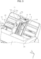
- FIG. 3 illustrates a state in which the restriction part 21 is housed in a housing portion 24 of the first edge guide 12b
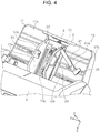
- FIG. 4 illustrates a state in the middle of switching between the state in which the restriction part 21 is in the first state ( FIG. 5 ) and the state in which the restriction part 21 is housed in the housing portion 24 ( FIG. 3 ). Since the restriction part 21 is retracted from between the first edge guide 12b and the second edge guide 12a also in the state in FIG. 4 , it can be said that the state in FIG. 4 is the second state.
- the second state of the restriction part 21 is described below with reference to FIG. 3 .
- a narrow and long medium P ( FIG. 7 ), such as a register tape printed by a register, may be read.
- the medium feed device 10 feeds a narrow and long medium P
- skew is accumulated during feed because the medium P is long, and the medium P may be twisted as illustrated in FIG. 7 .
- the medium P on the placement surface 11a may be twisted due to the weight of the hanging medium P.
- edges E1 and E2 of the medium P may be separated from the guide surfaces 13b and 13a, and the first edge guide 12b and the second edge guide 12a no longer provide the guide function.
- the skew of the medium P may further increase.
- the restriction part 21 can suppress a lift of the medium P from the placement surface 11a and suppress separation of the edges E1 and E2 of the medium P from the guide surfaces 13b and 13a. Hence, occurrence of skew at the medium P can be suppressed as compared with the case in which the restriction part 21 is in the second state ( FIG. 3 ).
- the restriction part 21 in the first state ( FIG. 5 ) is located at a position close to the placement surface 11a in the direction normal to the placement surface 11a (+Z side) as illustrated in FIG. 6 .
- the distance between the restriction part 21 and the placement surface 11a is a certain distance in which one to several media P can be placed, and is, for example, a distance in a range for several millimeters (2 to 3 mm) for example.
- the restriction part 21 Since the restriction part 21 is located at the position close to the placement surface 11a in the first state ( FIG. 5 ), the restriction part 21 can further reliably press the medium P, and can further effectively suppress occurrence of skew at the medium P.
- the restriction part 21 When the restriction part 21 is in the first state ( FIG. 5 ), only several media P can be placed on the medium placement part 11. However, since the restriction part 21 is configured to be switched between the first state ( FIG. 5 ) and the second state ( FIG. 3 ), in a case where the medium P is a medium that is less likely skewed (for example, a standard-size medium of A4 size, B5 size, etc.; or normal paper or thick paper in terms of medium type) as compared with a narrow and long medium such as a register tape, the restriction part 21 is brought into the second state ( FIG. 3 ). Thus, the maximum stack number of media P on the medium placement part 11 can be larger than that when the restriction part 21 is in the first state ( FIG. 5 ). When the restriction part 21 is in the second state ( FIG. 3 ), media P can be placed up to the maximum stack number on the medium placement part 11 (up to the position of the upper ends A in FIG. 6 ).
- the restriction part 21 When the restriction part 21 is in the second state (
- the second edge guide 12a includes a receiving portion 22 ( FIG. 4 ) that receives the free-end side of the restriction part 21.
- the restriction part 21 presses the medium P entirely in the width direction, the medium P can be more reliably prevented from being skewed.
- the restriction part 21 is substantially parallel to the placement surface 11a when the free-end side is engaged with the receiving portion 22.
- the switching between the first state and the second state of the restriction part 21 can be provided using, for example, the following configuration.
- the restriction part 21 is switched between the first state ( FIG. 5 ) and the second state ( FIG. 3 ) when the restriction part 21 pivots on, as an axis, a pivot shaft 23 provided in the first edge guide 12b.
- the restriction part 21 when the restriction part 21 is switched to the second state ( FIG. 3 ), the restriction part 21 is housed in the housing portion 24 provided in the first edge guide 12b.
- the housing portion 24 ( FIG. 4 ) is provided in a surface on the -X side (a surface opposite to the guide surface 13b) of the first edge guide 12b and has a slit shape.
- the housing portion 24 is accommodated within the thickness in the width direction of the first edge guide 12b (X-axis direction).
- the restriction part 21 when the restriction part 21 is not required to press media, the restriction part 21 can be housed in the housing portion 24.
- the second edge guide 12a includes the receiving portion 22 ( FIG. 4 ) that receives the free-end side of the restriction part 21.
- the restriction part 21 includes positioning portions 27a and 27b ( FIGS. 4 and 5 ) that set the distance between the second edge guide 12a and the first edge guide 12b to predetermined distances when the free-end side is received by the receiving portion 22.
- the positioning portions 27a and 27b may use a configuration that can easily switch the state between a fixed state and a released state, for example, a latch structure or a snap-fit structure.
- a register tape that is an example of a narrow and long medium P includes, as stand sizes, a 50-mm-wide medium and an 80-mm-wide medium.
- the positioning portion 27a positions the distance between the second edge guide 12a and the first edge guide 12b at a distance corresponding to the 50-mm-wide register tape
- the positioning portion 27b positions the distance between the second edge guide 12a and the first edge guide 12b at a distance corresponding to the 80-mm-wide register tape.
- the restriction part 21 includes the positioning portions 27a and 27b, the distance between the second edge guide 12a and the first edge guide 12b can be set to the predetermined distances.
- the free end of the restriction part 21 is formed in an L-like shape and hence a contact portion 26 is formed.
- the contact portion 26 is a component portion that restricts movement of the second edge guide 12a to the +X side such that the distance between the second edge guide 12a and the first edge guide 12b does not become larger than the distance corresponding to the width of 80 mm.
- the medium feed device 10 according to the above-described first embodiment can be summarized as follows.
- a medium feed device 10 illustrated in FIGS. 3 to 6 includes a medium placement part 11 including a placement surface 11a configured to have placed thereon a medium P to be fed; a pair of a first edge guide 12b and a second edge guide 12a that are provided at the medium placement part 11 and that include guide surfaces 13b and 13a that guide edges E in a width direction (X-axis direction) of the medium P, the width direction intersecting with a feed direction (+Y side) of the medium P; and a restriction part 21 that is configured to be switched between a first state ( FIG. 5 ) and a second state ( FIG. 3 ).
- the restriction part 21 extends in the width direction between the first edge guide 12b and the second edge guide 12a, a position of the restriction part 21 in a direction normal to the placement surface 11a (+Z side) is located on a placement surface 11a side with respect to an intermediate position B ( FIG. 6 ) between upper ends A ( FIG. 6 ) of the guide surfaces 13b and 13a and the placement surface 11a, and the restriction part 21 suppresses a lift of the medium P from the placement surface 11a.
- the restriction part 21 is retracted from between the first edge guide 12b and the second edge guide 12a.
- a medium feed device 10 includes a medium placement part 11 including a placement surface 11a configured to have placed thereon a medium P to be fed; a pair of a first edge guide 12b and a second edge guide 12a that are provided at the medium placement part 11 and that include guide surfaces 13b and 13a that guide edges E in a width direction (X-axis direction) of the medium P, the width direction intersecting with a feed direction (+Y side) of the medium P; and a restriction part 21 that is configured to be switched between a first state ( FIG. 5 ) and a second state ( FIG. 3 ).
- the restriction part 21 extends in the width direction between the first edge guide 12b and the second edge guide 12a, a position of the restriction part 21 in a direction normal to the placement surface 11a (+Z side) is a position at which the restriction part 21 suppresses a lift of the medium P from the placement surface 11a and is a position at which the restriction part 21 suppresses separation (a state in FIG. 7 ) of the edges E of the medium P from the guide surfaces 13b and 13a.
- the restriction part 21 is retracted from between the first edge guide 12b and the second edge guide 12a.
- the restriction part 21 presses a medium P that is likely lifted from the placement surface 11a, and occurrence of skew at the medium P can be restricted.
- the restriction part 21 When the medium P is less likely lifted and the restriction part 21 does not have to press the medium, by bringing the restriction part 21 into the second state ( FIG. 3 ), the maximum stack number of media P on the medium placement part 11 can be larger than that when the restriction part 21 is in the first state ( FIG. 5 ).
- FIG. 8 illustrates a medium feed device 30 that is a modification of the first embodiment.
- a restriction part 31 includes two restriction portions 31a and 31b that are shorter than the restriction part 21 of the first embodiment.
- the restriction portion 31a has a pivot shaft 32a at the second edge guide 12a and is configured to be housed in the second edge guide 12a.
- the restriction portion 31b has a pivot shaft 32b at the first edge guide 12b and is configured to be housed in the first edge guide 12b.
- the restriction portion 31a and the restriction portion 31b indicated by solid lines are in the first state
- the restriction portion 31a and the restriction portion 31b indicated by dotted lines are in the second state stored in the second edge guide 12a and the first edge guide 12b.
- the restriction portion 31a and the restriction portion 31b are arranged substantially in parallel to the placement surface 11a.
- free ends of the restriction portion 31a and the restriction portion 31b may contact the placement surface 11a in the first state like a restriction part 42 according to a second embodiment (described later).
- a center region of a medium P can be reliably pressed, and a lift of the medium P from the placement surface 11a can be effectively suppressed.
- FIG. 11 illustrates the first state with a medium P.
- a medium feed device 41 includes a medium placement part 11 including a placement surface 11a configured to have placed thereon a medium P to be fed; a pair of a first edge guide 12b and a second edge guide 12a that are provided at the medium placement part 11 and that include guide surfaces 13b and 13a that guide edges in a width direction (X-axis direction) of the medium P, the width direction intersecting with a feed direction (+Y side) of the medium P; and a restriction part 42 that is configured to be switched between a first state and a second state.
- the restriction part 42 presses the medium P to the placement surface 11a between the first edge guide 12b and the second edge guide 12a.
- the restriction part 42 is separated from the medium P on the placement surface 11a, and that suppresses a lift of the medium P from the placement surface 11a in the first state.
- the pressing force of the restriction part 42 to the placement surface 11a for the medium P in the first state can act, for example, using the weight of the restriction part 42.
- a pressure force can act using a pressure force of a pressing member such as a spring.
- the restriction part 42 By bringing the restriction part 42 into the first state, the restriction part 42 directly presses the medium P, and hence can further reliably suppress a lift of the medium P. Thus, occurrence of skew at the medium P can be suppressed as compared with the case where the restriction part 42 is in the second state.
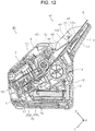
- the restriction part 42 is switched between the first state (the restriction part 42 illustrated in FIG. 11 and indicated by solid lines in FIG. 12 ) and the second state (the restriction part 42 illustrated in FIG. 9 and indicated by dotted lines in FIG. 12 ) when the restriction part 42 pivots on, as an axis, a pivot shaft 44 ( FIG. 12 ) provided in the casing 2 having arranged therein the feed roller 14 (feed unit) that feeds the medium P.
- the restriction part 42 can be switched between the first state and the second state.
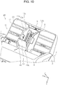
- FIG. 10 illustrates a state in the middle of switching between the second state illustrated in FIG. 9 and the first state illustrated in FIG. 11 .
- the restriction part 42 when a medium P that is less likely skewed is to be fed, the restriction part 42 is brought into the second state, and hence the maximum stack number of media on the medium placement part 11 can be larger than that when the restriction part 42 is in the first state.
- the length of the restriction part 42 in the width direction is set to a length corresponding to a 50-mm-wide register tape.
- the restriction part 42 can press substantially the entire region in the width direction of the medium P.
- the restriction part 42 does not press both end portions in the width direction of the medium P; however, it can press a center region in the width direction of the medium P.
- the restriction part 42 suppresses a lift of at least the center region in the width direction of the medium P from the placement surface 11a when the restriction part 42 is switched to the first state.
- the restriction part 42 presses the center region in the width direction of the medium P and suppresses a lift of the medium P from the placement surface 11a, the restriction part 42 can effectively suppress a lift of the medium P from the placement surface 11a.
- the restriction part 42 presses a medium P by a half or more of the length of the medium P in the width direction.
- the restriction part 42 can include a rotary body 45 (indicated by dotted lines in FIG. 12 ) such as a roller that rotates in the feed direction, at a contact portion 43 of the restriction part 42 with respect to a medium P.
- a rotary body 45 such as a roller that rotates in the feed direction, at a contact portion 43 of the restriction part 42 with respect to a medium P.
- the restriction part 42 includes the rotary body 45 at the contact portion 43 thereof, transport resistance that is generated when the restriction part 42 presses the medium P can be reduced.
- the medium feed device 10, 30, 41 is applied to the scanner as an example of the image reading apparatus.
- the medium feed device 10, 30, 41 may be applied to, for example, a printer.
Landscapes
- Engineering & Computer Science (AREA)
- Multimedia (AREA)
- Signal Processing (AREA)
- Mechanical Engineering (AREA)
- Sheets, Magazines, And Separation Thereof (AREA)
- Manual Feeding Of Sheets (AREA)
- Facsimiles In General (AREA)
Abstract
Description
- The present application is based on, and claims priority from
JP Application Serial Number 2018-086430, filed April, 27, 2018 - The present disclosure relates to a medium feed device and an image reading apparatus that reads an image on a medium that is fed by the medium feed device.
- A scanner serving as an example of an image reading apparatus may be provided with an automatic feed device for a medium serving as a document (also referred to as auto document feeder (ADF)) as a medium feed device, to automatically feed a plurality of media and read the media.
- In addition, there is such a medium feed device in which edge guides that are provided at a medium tray on which a medium is placed and that guide edges in a width direction of the medium are slidable in the width direction in accordance with the medium size.
- In the medium feed device, skew that is a phenomenon in which a medium is fed in an obliquely tilted state may occur.
- To suppress skew during feed of a medium,
JP-A-2017-165575 JP-A-2002-255357 upper guides 22 and 32 inJP-A-2017-165575 JP-A-2002-255357 - In
JP-A-2017-165575 JP-A-2002-255357 JP-A-2017- 165575 width guide parts 11 inJP-A-2002-255357 - With a scanner, there may be a user's request to read, for example, a narrow and long medium, such as a register tape printed by a register.
- In a case of a wide medium, even when an end portion in the width direction of the medium moves from the placement surface of the medium tray to the upper restriction part, the moving distance is small relative to the medium width, and hence the movement less likely appears as large skew of the medium. However, in a case of a narrow medium, when an end portion in the width direction of the medium moves from the placement surface of the medium tray to the upper restriction part, the moving distance is large relative to the medium width, and hence the movement appears as large skew of the medium. In particular, in a case of a narrow and long medium, skew based on the movement amount of the end portion in the width direction of the medium to the upper restriction part is accumulated as the medium is fed, and the medium may be largely twisted.
- An object of the present disclosure is to provide a medium feed device capable of appropriately feeding a medium whose skew likely noticeably appears, and an image reading apparatus including the medium feed device.
- According to an aspect of the present disclosure, a medium feed device includes a medium placement part including a placement surface configured to have placed thereon a medium to be fed; a pair of a first edge guide and a second edge guide that are provided at the medium placement part and that include guide surfaces that guide edges in a width direction of the medium, the width direction intersecting with a feed direction of the medium; and a restriction part configured to be switched between a first state and a second state. In the first state, the restriction part extends in the width direction between the first edge guide and the second edge guide, a position of the restriction part in a direction normal to the placement surface is on a placement surface side with respect to an intermediate position between upper ends of the guide surfaces and the placement surface, and the restriction part suppresses a lift of the medium from the placement surface. In the second state, the restriction part is retracted from between the first edge guide and the second edge guide.
- With the aspect, the medium feed device includes the restriction part configured to be switched between the first state and the second state. In the first state, the restriction part extends in the width direction between the first edge guide and the second edge guide, the position of the restriction part in the direction normal to the placement surface is on the placement surface side with respect to the intermediate position between the upper ends of the guide surfaces and the placement surface, and the restriction part suppresses the lift of the medium from the placement surface. In the second state, the restriction part is retracted from between the first edge guide and the second edge guide. Accordingly, by bringing the restriction part into the first state, occurrence of skew at the medium can be suppressed as compared with the case where the restriction part is in the second state.
- For example, when a medium that is less likely skewed is to be fed, by bringing the restriction part into the second state, the maximum stack number of media on the medium placement part can be larger than the case where the restriction part is in the first state.
- According to another aspect of the present disclosure, a medium feed device includes a medium placement part including a placement surface configured to have placed thereon a medium to be fed; a pair of a first edge guide and a second edge guide that are provided at the medium placement part and that include guide surfaces that guide edges in a width direction of the medium, the width direction intersecting with a feed direction of the medium; and a restriction part configured to be switched between a first state and a second state. In the first state, the restriction part extends in the width direction between the first edge guide and the second edge guide, a position of the restriction part in a direction normal to the placement surface is a position at which the restriction part suppresses a lift of the medium from the placement surface and a position at which the restriction part suppresses separation of the edges of the medium from the guide surfaces. In the second state, the restriction part is retracted from between the first edge guide and the second edge guide.
- With the aspect, the medium feed device includes the restriction part configured to be switched between the first state and the second state. In the first state, the restriction part extends in the width direction between the first edge guide and the second edge guide, the position of the restriction part in the direction normal to the placement surface is the position at which the restriction part suppresses the lift of the medium from the placement surface and the position at which the restriction part suppresses the separation of the edges of the medium from the guide surfaces. In the second state, the restriction part is retracted from between the first edge guide and the second edge guide. Accordingly, by bringing the restriction part into the first state, occurrence of skew at the medium can be suppressed as compared with the case where the restriction part is in the second state.
- For example, when a medium that is less likely skewed is to be fed, by bringing the restriction part into the second state, the maximum stack number of media on the medium placement part can be larger than the case where the restriction part is in the first state.
- In the medium feed device according to the present disclosure, the restriction part may be located at a position close to the placement surface in the direction normal to the placement surface.
- In this specification, "a position close to the placement surface" represents a position at a certain distance (for example, 2 to 3 mm) that one to several media can be placed between the restriction part and the placement surface.
- In this case, since the restriction part may be located at the position close to the placement surface in the direction normal to the placement surface in the first state, when the restriction part is in the first state, occurrence of skew at the medium can be further effectively suppressed.
- According to still another aspect of the present disclosure, a medium feed device includes a medium placement part including a placement surface configured to have placed thereon a medium to be fed; a pair of a first edge guide and a second edge guide that are provided at the medium placement part and that include guide surfaces that guide edges in a width direction of the medium, the width direction intersecting with a feed direction of the medium; and a restriction part configured to be switched between a first state and a second state. In the first state, the restriction part presses the medium to the placement surface between the first edge guide and the second edge guide. In the second state, the restriction part is separated from the medium on the placement surface. The restriction part restricts a lift of the medium from the placement surface in the first state.
- With the aspect, the medium feed device includes the restriction part configured to be switched between the first state and the second state. In the first state, the restriction part presses the medium to the placement surface between the first edge guide and the second edge guide. In the second state, the restriction part is separated from the medium on the placement surface. The restriction part restricts the lift of the medium from the placement surface in the first state. Accordingly, by bringing the restriction part into the first state, occurrence of skew at the medium can be suppressed as compared with the case where the restriction part is in the second state.
- For example, when a medium that is less likely skewed is to be fed, by bringing the restriction part into the second state, the maximum stack number of media on the medium placement part can be larger than the case where the restriction part is in the first state.
- In the medium feed device according to the present disclosure, the restriction part may include a rotary body that is provided at a contact potion of the restriction part with respect to the medium and that rotates in the feed direction.
- In this case, since the restriction part may include the rotary body that is provided at the contact potion of the restriction part with respect to the medium and that rotates in the feed direction, transport resistance that is generated when the restriction part presses the medium can be reduced.
- In the medium feed device according to the present disclosure, the restriction part may suppress a lift of at least a center region in the width direction of the medium from the placement surface when the restriction part is switched to the first state.
- In this case, since the restriction part may suppress the lift of at least the center region in the width direction of the medium from the placement surface when the restriction part is switched to the first state, a lift of the medium from the placement surface can be effectively suppressed.
- In the medium feed device according to the present disclosure, the restriction part may be switched between the first state and the second state when the restriction part pivots on, as an axis, a pivot shaft provided at the first edge guide.
- In this case, since the restriction part may be switched between the first state and the second state when the restriction part pivots on, as the axis, the pivot shaft provided at the first edge guide, the configuration that switches the state of the restriction part between the first state and the second state can be easily provided.
- In the medium feed device according to the present disclosure, a free-end side of the restriction part may reach the second edge guide when the restriction part is switched to the first state.
- In this case, since the free-end side of the restriction part may reach the second edge guide when the restriction part is switched to the first state, the restriction part presses the medium entirely in the width direction, and the medium can be more reliably prevented from being skewed.
- In the medium feed device according to the present disclosure, the second edge guide may include a receiving portion that receives the free-end side of the restriction part, and the restriction part may include a positioning portion that sets a distance between the second edge guide and the first edge guide to a predetermined distance when the free-end side is received by the receiving portion.
- In this case, since the second edge guide may include the receiving portion that receives the free-end side of the restriction part, and the restriction part may include the positioning portion that sets the distance between the second edge guide and the first edge guide to the predetermined distance when the free-end side is received by the receiving portion, the distance between the second edge guide and the first edge guide can be set to the predetermined distance.
- In the medium feed device according to the present disclosure, the restriction part may be housed in a housing portion provided in the first edge guide when the restriction part is switched to the second state.
- In this case, since the restriction part may be housed in the housing portion provided in the first edge guide when the restriction part is switched to the second state, in a case where the restriction part is not required to press the medium, the restriction part can be housed in the housing portion.
- In the medium feed device according to the present disclosure, the restriction part may be switched between the first state and the second state when the restriction part pivots on, as an axis, a pivot shaft provided in a casing having arranged therein a feed unit that feeds the medium.
- In this case, since the restriction part may be switched between the first state and the second state when the restriction part pivots on, as the axis, the pivot shaft provided in the casing having arranged therein the feed unit that feeds the medium, the configuration that switches the state of the restriction part between the first state and the second state can be easily provided.
- According to yet another aspect of the present disclosure, an image reading apparatus includes a reading unit that reads an image on the medium; and the medium feed device according to any one of the above-described aspects that feeds the medium toward the reading unit.
- With the aspect, the image reading apparatus including the reading unit that reads the image on the medium; and the medium feed device that feeds the medium toward the reading unit can attain advantageous effects similar to those of the above-described aspects.
- Embodiments of the present invention will now be described by way of further example only and with reference to the accompanying drawings, in which:
-
FIG. 1 is an external perspective view showing a scanner according to a first embodiment. -
FIG. 2 is a side sectional view illustrating a medium transport path in the scanner according to the first embodiment. -
FIG. 3 illustrates a second state in which a restriction part is housed in a first edge guide in a medium feed device according to the first embodiment. -
FIG. 4 illustrates a state in the middle of switching when the restriction part is switched between the second state illustrated inFIG. 3 and a first state in the medium feed device according to the first embodiment. -
FIG. 5 illustrates the first state of the restriction part in the medium feed device according to the first embodiment. -
FIG. 6 is a side sectional view ofFIG. 5 . -
FIG. 7 illustrates a state in which a narrow and long medium is lifted from a placement surface in the medium feed device when the restriction part is in the second state. -
FIG. 8 is an illustration explaining a modification of the restriction part. -
FIG. 9 illustrates a second state of a restriction part in a medium feed device according to a second embodiment. -
FIG. 10 illustrates a state in the middle of switching when the restriction part is switched between the second state illustrated inFIG. 9 and a first state in the medium feed device according to the second embodiment. -
FIG. 11 illustrates the first state of the restriction part in the medium feed device according to the second embodiment. -
FIG. 12 is a side sectional view of a scanner according to the second embodiment. - An image reading apparatus according to an embodiment of the present disclosure is briefly described first. A document scanner 1 (hereinafter, merely referred to as scanner 1) configured to read at least one surface of a front surface and a back surface of a medium is described as an example of the image reading apparatus in this embodiment.
- Regarding the X-Y-Z coordinate system in each drawing, the X direction is an apparatus width direction and a medium width direction, and the Y direction is a medium transport direction. The Z direction is a direction intersecting with the Y direction, and indicates a direction substantially orthogonal to a plane of a medium to be transported. It is assumed that the +Y side is an apparatus front-surface side, and the -Y side is an apparatus rear-surface side. It is assumed that the left side when viewed from the apparatus front-surface side is the +X side, and the right side is the -X side. The +Z side is an apparatus upper side (including an upper section, an upper surface, and so forth), and the -Z side is an apparatus lower side (including a lower section, a lower surface, and so forth). A side to which a medium is fed (+Y side) is referred to as "downstream side", and a side (-Y side) opposite to the downstream side is referred to as "upstream side".
- The scanner 1 according to the present disclosure is described below with reference to
FIGS. 1 to 3 . - The scanner 1 illustrated in
FIG. 1 includes acasing 2 including therein a reading unit 20 (FIG. 2 ) that reads an image on a medium P and amedium feed device 10 that feeds a medium toward thereading unit 20. - The
casing 2 includes alower unit 3 and anupper unit 4. Theupper unit 4 is attached to thelower unit 3 to be openable and closable about the downstream side in the medium transport direction as the pivot. Theupper unit 4 pivots to the apparatus front-surface side to be open, a medium transport path of a medium P (indicated by a dotted line inFIG. 2 ) is exposed, and hence a paper jam of the medium P can be easily cleared. - In
FIG. 1 , amedium placement part 11, afirst edge guide 12b and asecond edge guide 12a, and arestriction part 21 that constitute themedium feed device 10 are provided on the apparatus rear-surface side (-Y side) of the casing 2 (also seeFIG. 3 ). - The
medium placement part 11 includes aplacement surface 11a on which a medium P to be fed is placed. Themedium placement part 11 is removably attached to thecasing 2. - A pair of the
first edge guide 12b and thesecond edge guide 12a are provided at themedium placement part 11, and include aguide surface 13b and aguide surface 13a that guide edges in the width direction (X-axis direction) of the medium P, the width direction intersecting with the feed direction of the medium P (Y-axis direction). Thefirst edge guide 12b forms theguide surface 13b, and thesecond edge guide 12a forms theguide surface 13a. - A
sign 25 is provided on theguide surface 13a of thesecond edge guide 12a, and indicates the upper limit position when media P are placed by the maximum stack number of media P on themedium placement part 11. Although not illustrated inFIG. 1 , asimilar sign 25 is also provided on theguide surface 13b of thefirst edge guide 12b. - The
first edge guide 12b and thesecond edge guide 12a are provided slidably in the X-axis direction in accordance with the size of the medium P. In this embodiment, thefirst edge guide 12b and thesecond edge guide 12a are configured such that, when one edge guide (for example, thefirst edge guide 12b) is moved by a known rack-and-pinion mechanism to one side in the X-axis direction, the other edge guide (thesecond edge guide 12a) is moved to the other side in the X-axis direction by following the X-axis movement of the one edge guide. - Thus, media P placed on the
medium placement part 11 are aligned at the center in the width direction. -
FIG. 1 illustrates a state in which the edge guides 12 are located at positions on the outermost sides.FIG. 3 illustrates a state in which the edge guides 12 are located at positions on the innermost sides. - The
restriction part 21 that is a main feature of the present disclosure will be described later in detail. - The
medium placement part 11 illustrated inFIGS. 1 and3 includes a firstauxiliary paper support 8 and a secondauxiliary paper support 9. The firstauxiliary paper support 8 and the secondauxiliary paper support 9 are configured to be housed in themedium placement part 11 as illustrated inFIG. 3 , and pulled out from themedium placement part 11 as illustrated inFIG. 1 . The length of theplacement surface 11a is adjustable. - The
casing 2 illustrated inFIG. 1 includes anoperation panel 7 on the apparatus front-surface side (+Y side) of theupper unit 4 for inputting instructions to adjust various reading settings, for starting an operation to execute reading, for indication of the contents of the reading settings, and so forth. - A
feed port 6 continuous to the inside of thecasing 2 is provided at an upper section of theupper unit 4. A medium P placed on themedium placement part 11 is fed through thefeed port 6 toward the reading unit 20 (FIG. 2 ). - In addition, an output tray 5 (described later) is provided on the apparatus front-surface side of the
lower unit 3. - The medium transport path in the scanner 1 is described next with reference to
FIG. 2 . The dotted line denoted by reference sign P inFIG. 2 indicates a medium P that is transported along the medium transport path. - A
feed roller 14 and aseparation roller 15 are provided downstream of themedium placement part 11. Thefeed roller 14 serves as "a feed unit" that feeds the medium P placed on theplacement surface 11a of themedium placement part 11 toward thereading unit 20. Theseparation roller 15 nips and separates the medium P between theseparation roller 15 and thefeed roller 14. - The medium P placed on the
placement surface 11a of themedium placement part 11 is picked up by thefeed roller 14 provided rotatably relative to thelower unit 3, and is fed to the downstream side (+Y side). More specifically, thefeed roller 14 contacts a surface of the medium P facing theplacement surface 11a and rotates. Hence thefeed roller 14 feeds the medium P to the downstream side. When a plurality of media P are set on themedium placement part 11 in the scanner 1, the media P are fed to the downstream side in order from the medium P on theplacement surface 11a side to the medium P furthest from theplacement surface 11a side. - The
feed roller 14 and theseparation roller 15 are provided in a center region in the width direction (X-axis direction). The medium P is fed using a center feed system. - A
transport roller pair 16, thereading unit 20 that reads an image, and anoutput roller pair 17 are provided downstream of thefeed roller 14. The medium P fed to the downstream side by thefeed roller 14 is nipped by thetransport roller pair 16, and is transported to thereading unit 20 located downstream of thetransport roller pair 16. - The
reading unit 20 includes anupper reading sensor 20a provided on theupper unit 4 side, and alower reading sensor 20b provided on thelower unit 3 side. In this embodiment, theupper reading sensor 20a and thelower reading sensor 20b are configured as a contact image sensor module (CISM) for example. - After an image on at least one of front and back surfaces of the medium P is read by the
reading unit 20, the medium P is nipped by theoutput roller pair 17 located downstream of thereading unit 20 and fed to the downstream side, and the medium P is output from anoutput port 18 provided on the apparatus front-surface side of thecasing 2. - In this embodiment, the
feed roller 14, thetransport roller pair 16, and theoutput roller pair 17 are rotationally driven by at least one drive source (not illustrated) provided in thelower unit 3. The drive source is controlled by a controller (not illustrated), and thus, the drive of thefeed roller 14, thetransport roller pair 16, and theoutput roller pair 17 is controlled. - The
output tray 5 is provided at thelower unit 3. Theoutput tray 5 is configured to be pulled out from theoutput port 18 to the apparatus front-surface side. Theoutput tray 5 may be in a state in which theoutput tray 5 is housed in a bottom section of the lower unit 3 (FIG. 1 ), and a state in which theoutput tray 5 is pulled out to the apparatus front-surface side (not illustrated). In the state in which theoutput tray 5 is pulled out, media P output from theoutput port 18 can be stacked on theoutput tray 5. - The
restriction part 21 provided in themedium feed device 10 is described next with reference toFIGS. 3 to 6 . - The
restriction part 21 illustrated inFIGS. 3 to 6 is configured to be switched between a first state (FIG. 5 ) and a second state (FIG. 3 ) which will be described later. - In the first state, the
restriction part 21 extends in the width direction (X-axis direction) between thefirst edge guide 12b and thesecond edge guide 12a as illustrated inFIG. 5 ; the position of therestriction part 21 in the direction normal to theplacement surface 11a (+Z side) is located on theplacement surface 11a side with respect to an intermediate position B (a position indicated by a one-dot chain line inFIG. 6 ) between upper ends A of the guide surfaces 13b and 13a (a position indicated by a two-dot chain line inFIG. 6 ) and theplacement surface 11a as illustrated inFIG. 6 ; and therestriction part 21 suppresses a lift of the medium P from theplacement surface 11a. The guide surfaces 13b and 13a do not guide media P at a position above thesign 25 in the direction normal to theplacement surface 11a, and hence the upper ends A of the guide surfaces 13b and 13a are at a position at which the upper ends A overlap thesign 25. - In the second state, the
restriction part 21 is retracted from between thefirst edge guide 12b and thesecond edge guide 12a as illustrated inFIG. 3 . This preferably means that in the second state therestriction part 21 does not extend between thefirst edge guide 12b and thesecond edge guide 12a and does not suppress a lift of the medium P from theplacement surface 11a. - Although described later,
FIG. 3 illustrates a state in which therestriction part 21 is housed in ahousing portion 24 of thefirst edge guide 12b, andFIG. 4 illustrates a state in the middle of switching between the state in which therestriction part 21 is in the first state (FIG. 5 ) and the state in which therestriction part 21 is housed in the housing portion 24 (FIG. 3 ). Since therestriction part 21 is retracted from between thefirst edge guide 12b and thesecond edge guide 12a also in the state inFIG. 4 , it can be said that the state inFIG. 4 is the second state. The second state of therestriction part 21 is described below with reference toFIG. 3 . - With the scanner 1, a narrow and long medium P (
FIG. 7 ), such as a register tape printed by a register, may be read. When themedium feed device 10 feeds a narrow and long medium P, skew is accumulated during feed because the medium P is long, and the medium P may be twisted as illustrated inFIG. 7 . In addition, when the long medium P hangs down from the firstauxiliary paper support 8 or the secondauxiliary paper support 9, the medium P on theplacement surface 11a may be twisted due to the weight of the hanging medium P. - When the medium P is twisted, as illustrated in
FIG. 7 , edges E1 and E2 of the medium P may be separated from the guide surfaces 13b and 13a, and thefirst edge guide 12b and thesecond edge guide 12a no longer provide the guide function. Thus, the skew of the medium P may further increase. - In this case, by bringing the
restriction part 21 into the first state (FIG. 5 ), therestriction part 21 can suppress a lift of the medium P from theplacement surface 11a and suppress separation of the edges E1 and E2 of the medium P from the guide surfaces 13b and 13a. Hence, occurrence of skew at the medium P can be suppressed as compared with the case in which therestriction part 21 is in the second state (FIG. 3 ). - In this embodiment, the
restriction part 21 in the first state (FIG. 5 ) is located at a position close to theplacement surface 11a in the direction normal to theplacement surface 11a (+Z side) as illustrated inFIG. 6 . - In
FIG. 6 , the distance between therestriction part 21 and theplacement surface 11a is a certain distance in which one to several media P can be placed, and is, for example, a distance in a range for several millimeters (2 to 3 mm) for example. - Since the
restriction part 21 is located at the position close to theplacement surface 11a in the first state (FIG. 5 ), therestriction part 21 can further reliably press the medium P, and can further effectively suppress occurrence of skew at the medium P. - When the
restriction part 21 is in the first state (FIG. 5 ), only several media P can be placed on themedium placement part 11. However, since therestriction part 21 is configured to be switched between the first state (FIG. 5 ) and the second state (FIG. 3 ), in a case where the medium P is a medium that is less likely skewed (for example, a standard-size medium of A4 size, B5 size, etc.; or normal paper or thick paper in terms of medium type) as compared with a narrow and long medium such as a register tape, therestriction part 21 is brought into the second state (FIG. 3 ). Thus, the maximum stack number of media P on themedium placement part 11 can be larger than that when therestriction part 21 is in the first state (FIG. 5 ). When therestriction part 21 is in the second state (FIG. 3 ), media P can be placed up to the maximum stack number on the medium placement part 11 (up to the position of the upper ends A inFIG. 6 ). - In addition, when the
restriction part 21 is switched to the first state as illustrated inFIG. 5 , the free-end side of therestriction part 21 reaches thesecond edge guide 12a. Thesecond edge guide 12a includes a receiving portion 22 (FIG. 4 ) that receives the free-end side of therestriction part 21. - Accordingly, since the
restriction part 21 presses the medium P entirely in the width direction, the medium P can be more reliably prevented from being skewed. - The
restriction part 21 is substantially parallel to theplacement surface 11a when the free-end side is engaged with the receivingportion 22. - The switching between the first state and the second state of the
restriction part 21 can be provided using, for example, the following configuration. - That is, the
restriction part 21 is switched between the first state (FIG. 5 ) and the second state (FIG. 3 ) when therestriction part 21 pivots on, as an axis, apivot shaft 23 provided in thefirst edge guide 12b. - In addition, when the
restriction part 21 is switched to the second state (FIG. 3 ), therestriction part 21 is housed in thehousing portion 24 provided in thefirst edge guide 12b. - The housing portion 24 (
FIG. 4 ) is provided in a surface on the -X side (a surface opposite to theguide surface 13b) of thefirst edge guide 12b and has a slit shape. Thehousing portion 24 is accommodated within the thickness in the width direction of thefirst edge guide 12b (X-axis direction). - With this configuration, when the
restriction part 21 is not required to press media, therestriction part 21 can be housed in thehousing portion 24. - The
second edge guide 12a includes the receiving portion 22 (FIG. 4 ) that receives the free-end side of therestriction part 21. Therestriction part 21 includespositioning portions FIGS. 4 and5 ) that set the distance between thesecond edge guide 12a and thefirst edge guide 12b to predetermined distances when the free-end side is received by the receivingportion 22. - The
positioning portions - A register tape that is an example of a narrow and long medium P includes, as stand sizes, a 50-mm-wide medium and an 80-mm-wide medium. In this embodiment, the
positioning portion 27a positions the distance between thesecond edge guide 12a and thefirst edge guide 12b at a distance corresponding to the 50-mm-wide register tape, and thepositioning portion 27b positions the distance between thesecond edge guide 12a and thefirst edge guide 12b at a distance corresponding to the 80-mm-wide register tape. - Since the
restriction part 21 includes thepositioning portions second edge guide 12a and thefirst edge guide 12b can be set to the predetermined distances. - In addition, the free end of the
restriction part 21 is formed in an L-like shape and hence acontact portion 26 is formed. Thecontact portion 26 is a component portion that restricts movement of thesecond edge guide 12a to the +X side such that the distance between thesecond edge guide 12a and thefirst edge guide 12b does not become larger than the distance corresponding to the width of 80 mm. - The
medium feed device 10 according to the above-described first embodiment can be summarized as follows. - A
medium feed device 10 illustrated inFIGS. 3 to 6 includes amedium placement part 11 including aplacement surface 11a configured to have placed thereon a medium P to be fed; a pair of afirst edge guide 12b and asecond edge guide 12a that are provided at themedium placement part 11 and that include guide surfaces 13b and 13a that guide edges E in a width direction (X-axis direction) of the medium P, the width direction intersecting with a feed direction (+Y side) of the medium P; and arestriction part 21 that is configured to be switched between a first state (FIG. 5 ) and a second state (FIG. 3 ). In the first state, therestriction part 21 extends in the width direction between thefirst edge guide 12b and thesecond edge guide 12a, a position of therestriction part 21 in a direction normal to theplacement surface 11a (+Z side) is located on aplacement surface 11a side with respect to an intermediate position B (FIG. 6 ) between upper ends A (FIG. 6 ) of the guide surfaces 13b and 13a and theplacement surface 11a, and therestriction part 21 suppresses a lift of the medium P from theplacement surface 11a. In the second state, therestriction part 21 is retracted from between thefirst edge guide 12b and thesecond edge guide 12a. - In another point of view, a
medium feed device 10 includes amedium placement part 11 including aplacement surface 11a configured to have placed thereon a medium P to be fed; a pair of afirst edge guide 12b and asecond edge guide 12a that are provided at themedium placement part 11 and that include guide surfaces 13b and 13a that guide edges E in a width direction (X-axis direction) of the medium P, the width direction intersecting with a feed direction (+Y side) of the medium P; and arestriction part 21 that is configured to be switched between a first state (FIG. 5 ) and a second state (FIG. 3 ). In the first state, therestriction part 21 extends in the width direction between thefirst edge guide 12b and thesecond edge guide 12a, a position of therestriction part 21 in a direction normal to theplacement surface 11a (+Z side) is a position at which therestriction part 21 suppresses a lift of the medium P from theplacement surface 11a and is a position at which therestriction part 21 suppresses separation (a state inFIG. 7 ) of the edges E of the medium P from the guide surfaces 13b and 13a. In the second state, therestriction part 21 is retracted from between thefirst edge guide 12b and thesecond edge guide 12a. - Since the
medium feed device 10 includes therestriction part 21, by bringing therestriction part 21 into the first state (FIG. 5 ), therestriction part 21 presses a medium P that is likely lifted from theplacement surface 11a, and occurrence of skew at the medium P can be restricted. - When the medium P is less likely lifted and the
restriction part 21 does not have to press the medium, by bringing therestriction part 21 into the second state (FIG. 3 ), the maximum stack number of media P on themedium placement part 11 can be larger than that when therestriction part 21 is in the first state (FIG. 5 ). -
FIG. 8 illustrates amedium feed device 30 that is a modification of the first embodiment. In themedium feed device 30, arestriction part 31 includes tworestriction portions restriction part 21 of the first embodiment. - The
restriction portion 31a has apivot shaft 32a at thesecond edge guide 12a and is configured to be housed in thesecond edge guide 12a. Therestriction portion 31b has apivot shaft 32b at thefirst edge guide 12b and is configured to be housed in thefirst edge guide 12b. - In
FIG. 8 , therestriction portion 31a and therestriction portion 31b indicated by solid lines are in the first state, and therestriction portion 31a and therestriction portion 31b indicated by dotted lines are in the second state stored in thesecond edge guide 12a and thefirst edge guide 12b. - With this configuration, a lift of a medium P can be suppressed substantially in the entire region in the width direction.
- In the first state, the
restriction portion 31a and therestriction portion 31b are arranged substantially in parallel to theplacement surface 11a. However, free ends of therestriction portion 31a and therestriction portion 31b may contact theplacement surface 11a in the first state like arestriction part 42 according to a second embodiment (described later). Thus, a center region of a medium P can be reliably pressed, and a lift of the medium P from theplacement surface 11a can be effectively suppressed. - In the second embodiment, another example of the restriction part is described with reference to
FIGS. 9 to 12 . - In this embodiment, the same reference sign is applied to the same configuration of the first embodiment, and the description on the configuration is omitted.
- In a
medium feed device 41 provided at adocument scanner 40 according to the second embodiment, when arestriction part 42 is in a first state without a medium P on theplacement surface 11a (in a state of therestriction part 42 indicated by solid lines inFIG. 12 ), therestriction part 42 contacts theplacement surface 11a.FIG. 11 illustrates the first state with a medium P. - That is, a
medium feed device 41 includes amedium placement part 11 including aplacement surface 11a configured to have placed thereon a medium P to be fed; a pair of afirst edge guide 12b and asecond edge guide 12a that are provided at themedium placement part 11 and that include guide surfaces 13b and 13a that guide edges in a width direction (X-axis direction) of the medium P, the width direction intersecting with a feed direction (+Y side) of the medium P; and arestriction part 42 that is configured to be switched between a first state and a second state. In the first state, therestriction part 42 presses the medium P to theplacement surface 11a between thefirst edge guide 12b and thesecond edge guide 12a. In the second state, therestriction part 42 is separated from the medium P on theplacement surface 11a, and that suppresses a lift of the medium P from theplacement surface 11a in the first state. - The pressing force of the
restriction part 42 to theplacement surface 11a for the medium P in the first state can act, for example, using the weight of therestriction part 42. In addition to the pressing force using the weight of therestriction part 42, a pressure force can act using a pressure force of a pressing member such as a spring. - By bringing the
restriction part 42 into the first state, therestriction part 42 directly presses the medium P, and hence can further reliably suppress a lift of the medium P. Thus, occurrence of skew at the medium P can be suppressed as compared with the case where therestriction part 42 is in the second state. - In this embodiment, the
restriction part 42 is switched between the first state (therestriction part 42 illustrated inFIG. 11 and indicated by solid lines inFIG. 12 ) and the second state (therestriction part 42 illustrated inFIG. 9 and indicated by dotted lines inFIG. 12 ) when therestriction part 42 pivots on, as an axis, a pivot shaft 44 (FIG. 12 ) provided in thecasing 2 having arranged therein the feed roller 14 (feed unit) that feeds the medium P. - With this simple configuration, the
restriction part 42 can be switched between the first state and the second state. - In this embodiment, the
pivot shaft 44 is provided at a section located above thefeed port 6 in theupper unit 4 that constitutes thecasing 2.FIG. 10 illustrates a state in the middle of switching between the second state illustrated inFIG. 9 and the first state illustrated inFIG. 11 . - Similarly to the first embodiment, when a medium P that is less likely skewed is to be fed, the
restriction part 42 is brought into the second state, and hence the maximum stack number of media on themedium placement part 11 can be larger than that when therestriction part 42 is in the first state. - In this embodiment, the length of the
restriction part 42 in the width direction (X-axis direction) is set to a length corresponding to a 50-mm-wide register tape. Thus, as illustrated inFIG. 11 , when the distance between thesecond edge guide 12a and thefirst edge guide 12b is set to the distance for guiding the 50-mm-wide register tape (a medium P inFIG. 11 ), therestriction part 42 can press substantially the entire region in the width direction of the medium P. - When the distance between the
second edge guide 12a and thefirst edge guide 12b is set to the distance for guiding an 80-mm-wide register tape (a medium P inFIG. 11 ), therestriction part 42 does not press both end portions in the width direction of the medium P; however, it can press a center region in the width direction of the medium P. - That is, the
restriction part 42 suppresses a lift of at least the center region in the width direction of the medium P from theplacement surface 11a when therestriction part 42 is switched to the first state. - In the first state, since the
restriction part 42 presses the center region in the width direction of the medium P and suppresses a lift of the medium P from theplacement surface 11a, therestriction part 42 can effectively suppress a lift of the medium P from theplacement surface 11a. - It is desirable that the
restriction part 42 presses a medium P by a half or more of the length of the medium P in the width direction. - The
restriction part 42 can include a rotary body 45 (indicated by dotted lines inFIG. 12 ) such as a roller that rotates in the feed direction, at acontact portion 43 of therestriction part 42 with respect to a medium P. - Since the
restriction part 42 includes therotary body 45 at thecontact portion 43 thereof, transport resistance that is generated when therestriction part 42 presses the medium P can be reduced. - In any of the first and second embodiments, the
medium feed device medium feed device - The present disclosure is not limited to the above-described embodiments, and can be modified in various ways within the scope of the disclosure written in the claims. In a matter of course, the modifications are included in the scope of the disclosure.
Claims (12)
- A medium feed device (10) comprising:a medium placement part (11) including a placement surface (11a) configured to have placed thereon a medium (P) to be fed;a pair of a first edge guide (12b) and a second edge guide (12a) that are provided at the medium placement part and that include guide surfaces (13b, 13a) that guide edges (E) in a width direction (X) of the medium, the width direction intersecting with a feed direction (Y) of the medium; anda restriction part (21) movable between a first position and a second position, wherein the first position is between the first edge guide and the second edge guide such that a position of the restriction part in a height direction (Z) normal to the placement surface is located closer to the placement surface in the height direction than an intermediate position between upper ends of the guide surfaces and the placement surface.
- The medium feed device according to claim 1, wherein in the second position the restriction part does not extend between the first edge guide and the second edge guide.
- A medium feed device (10) comprising:a medium placement part (11) including a placement surface (11a) configured to have placed thereon a medium (P) to be fed;a pair of a first edge guide (12b) and a second edge guide (12a) that are provided at the medium placement part and that include guide surfaces (13b, 13a) that guide edges (E) in a width direction (X) of the medium, the width direction intersecting with a feed direction (Y) of the medium; anda restriction part (42) configured to take a first position between the first edge guide and the second edge guide, the restriction part at the first position being arranged to press the medium onto the placement surface.
- The medium feed device according to claim 3, wherein the restriction part is configured to be moved from the first position to a second position such that the restriction part is retracted away from a position between the first edge guide and the second edge guide.
- The medium feed device according to claim 4, wherein the restriction part includes a rotary body (45) that is provided at a contact potion of the restriction part with respect to the medium and that rotates in the feed direction.
- The medium feed device according to any one of claims 1 to 5, wherein the restriction part is adapted to suppress a lift of at least a center region in the width direction of the medium from the placement surface when the restriction part is in the first position.
- The medium feed device according to claim 2 or claim 3, wherein the restriction part (31a, 31b) is pivotably mounted on, as an axis, a pivot shaft (32a, 32b) provided at the first edge guide, and the restriction part is configured to move between the first position and the second position by pivoting on the pivot shaft.
- The medium feed device according to claim 7, wherein a free-end side of the restriction part extends to the second edge guide when the restriction part is in the first position.
- The medium feed device according to claim 8, wherein
the second edge guide includes a receiving portion (22) that receives the free-end side of the restriction part, and
the restriction part includes a positioning portion (27a, 27b) that sets a distance between the second edge guide and the first edge guide to a predetermined distance when the free-end side is received by the receiving portion. - The medium feed device according to any one of claims 7 to 9, wherein the restriction part is housed in a housing portion (24) provided in the first edge guide when the restriction part is in the second position.
- The medium feed device according to claim 4 or claim 5, wherein the restriction part (42) is pivotably mounted on, as an axis, a pivot shaft (44) provided in a casing (2) having arranged therein a feed unit (14) that feeds the medium, and the restriction part is configured to move between the first position and the second position by pivoting on the pivot shaft.
- An image reading apparatus (1) comprising:a reading unit (20) that reads an image on the medium; andthe medium feed device according to any one of claims 1 to 11, which feeds the medium toward the reading unit.
Applications Claiming Priority (1)
| Application Number | Priority Date | Filing Date | Title |
|---|---|---|---|
| JP2018086430A JP7099032B2 (en) | 2018-04-27 | 2018-04-27 | Media feeder and image reader |
Publications (2)
| Publication Number | Publication Date |
|---|---|
| EP3562133A1 true EP3562133A1 (en) | 2019-10-30 |
| EP3562133B1 EP3562133B1 (en) | 2021-04-07 |
Family
ID=66286203
Family Applications (1)
| Application Number | Title | Priority Date | Filing Date |
|---|---|---|---|
| EP19171063.1A Active EP3562133B1 (en) | 2018-04-27 | 2019-04-25 | Medium feed device and image reading apparatus |
Country Status (4)
| Country | Link |
|---|---|
| US (1) | US11267665B2 (en) |
| EP (1) | EP3562133B1 (en) |
| JP (1) | JP7099032B2 (en) |
| CN (1) | CN110418026B (en) |
Families Citing this family (2)
| Publication number | Priority date | Publication date | Assignee | Title |
|---|---|---|---|---|
| JP7424049B2 (en) | 2019-12-26 | 2024-01-30 | セイコーエプソン株式会社 | Media feeding device, image reading device |
| JP7577450B2 (en) * | 2020-02-07 | 2024-11-05 | キヤノン株式会社 | SHEET FEEDING DEVICE, IMAGE READING DEVICE, AND IMAGE FORMING APPARATUS |
Citations (5)
| Publication number | Priority date | Publication date | Assignee | Title |
|---|---|---|---|---|
| JP2002255357A (en) | 2001-03-02 | 2002-09-11 | Ricoh Co Ltd | Paper width regulating member, document conveying device, and recording paper conveying device |
| US20090322010A1 (en) * | 2008-06-25 | 2009-12-31 | Brother Kogyo Kabushiki Kaisha | Document Feeding Device |
| US20140064618A1 (en) * | 2012-08-29 | 2014-03-06 | Palo Alto Research Center Incorporated | Document information extraction using geometric models |
| JP2017165575A (en) | 2016-03-18 | 2017-09-21 | ブラザー工業株式会社 | Paper feeder and tray of paper feeder |
| JP2018086430A (en) | 2018-02-27 | 2018-06-07 | 株式会社三洋物産 | Game machine |
Family Cites Families (15)
| Publication number | Priority date | Publication date | Assignee | Title |
|---|---|---|---|---|
| JPS5757072Y2 (en) * | 1977-12-06 | 1982-12-08 | ||
| JPS5488787A (en) | 1977-12-26 | 1979-07-14 | Nippon Telegr & Teleph Corp <Ntt> | Photo diode array with fiber plate |
| JPH0616344A (en) * | 1992-07-03 | 1994-01-25 | Nisca Corp | Automatic document transporting device |
| JP3673638B2 (en) * | 1998-02-26 | 2005-07-20 | キヤノン株式会社 | Paper feeding device and image forming apparatus |
| US20060087686A1 (en) * | 1998-03-25 | 2006-04-27 | John Anderson | Decorating system for edible products |
| JP2001328752A (en) * | 2000-05-22 | 2001-11-27 | Ricoh Co Ltd | Manual paper feeder and image forming apparatus |
| JP3858687B2 (en) | 2001-12-20 | 2006-12-20 | 村田機械株式会社 | Paper transport device |
| JP2004083246A (en) * | 2002-08-28 | 2004-03-18 | Oki Data Corp | Paper feeder |
| US7637499B2 (en) * | 2006-02-09 | 2009-12-29 | Canon Kabushiki Kaisha | Sheet feeding apparatus and recording apparatus |
| JP2008133114A (en) * | 2006-11-29 | 2008-06-12 | Canon Inc | Sheet material stacking apparatus and image forming apparatus |
| JP2010149975A (en) * | 2008-12-24 | 2010-07-08 | Seiko Epson Corp | Skew correcting device and recorder |
| JP2010168129A (en) * | 2009-01-20 | 2010-08-05 | Canon Electronics Inc | Sheet feeding device |
| JP5771964B2 (en) * | 2010-01-07 | 2015-09-02 | 株式会社リコー | Storage device and image forming apparatus |
| JP2012074832A (en) * | 2010-09-28 | 2012-04-12 | Brother Ind Ltd | Image reading device |
| JP6724309B2 (en) | 2015-08-21 | 2020-07-15 | セイコーエプソン株式会社 | Processor |
-
2018
- 2018-04-27 JP JP2018086430A patent/JP7099032B2/en active Active
-
2019
- 2019-04-25 CN CN201910338310.7A patent/CN110418026B/en active Active
- 2019-04-25 US US16/394,732 patent/US11267665B2/en active Active
- 2019-04-25 EP EP19171063.1A patent/EP3562133B1/en active Active
Patent Citations (5)
| Publication number | Priority date | Publication date | Assignee | Title |
|---|---|---|---|---|
| JP2002255357A (en) | 2001-03-02 | 2002-09-11 | Ricoh Co Ltd | Paper width regulating member, document conveying device, and recording paper conveying device |
| US20090322010A1 (en) * | 2008-06-25 | 2009-12-31 | Brother Kogyo Kabushiki Kaisha | Document Feeding Device |
| US20140064618A1 (en) * | 2012-08-29 | 2014-03-06 | Palo Alto Research Center Incorporated | Document information extraction using geometric models |
| JP2017165575A (en) | 2016-03-18 | 2017-09-21 | ブラザー工業株式会社 | Paper feeder and tray of paper feeder |
| JP2018086430A (en) | 2018-02-27 | 2018-06-07 | 株式会社三洋物産 | Game machine |
Non-Patent Citations (1)
| Title |
|---|
| STANISLAS GUTEV: "Information Extraction from Images of Shopping Receipts", MASTER THESIS, 31 December 2011 (2011-12-31), pages 1 - 53, XP055042133, Retrieved from the Internet <URL:http://homepages.inf.ed.ac.uk/dcspaul/publications/StanMSC.pdf> [retrieved on 20121024] * |
Also Published As
| Publication number | Publication date |
|---|---|
| US11267665B2 (en) | 2022-03-08 |
| CN110418026B (en) | 2021-12-14 |
| JP2019189425A (en) | 2019-10-31 |
| US20190329996A1 (en) | 2019-10-31 |
| CN110418026A (en) | 2019-11-05 |
| JP7099032B2 (en) | 2022-07-12 |
| EP3562133B1 (en) | 2021-04-07 |
Similar Documents
| Publication | Publication Date | Title |
|---|---|---|
| EP2466867B1 (en) | Image forming apparatus | |
| JP6746989B2 (en) | Medium feeding device and image reading device | |
| EP2169935B1 (en) | Sheet transporting apparatus | |
| US10523831B2 (en) | Image reading apparatus | |
| JP6617871B2 (en) | Medium feeding device, image reading device, and recording device | |
| JPH03192039A (en) | Image reading-out device | |
| US11267665B2 (en) | Medium feed device and image reading apparatus | |
| JP2019089628A (en) | Medium feeding device, image reading device | |
| JP4194536B2 (en) | Image processing device | |
| US11381695B2 (en) | Image reading apparatus | |
| JP7424049B2 (en) | Media feeding device, image reading device | |
| JP4165541B2 (en) | Automatic document feeder and image reading apparatus | |
| JP5779969B2 (en) | Sheet transport device | |
| JP2010047395A (en) | Automatic document feeder | |
| JP2008133103A (en) | Medium feeding device, image reading device, and multifunction machine | |
| US7922166B2 (en) | Image reader | |
| US20260122192A1 (en) | Image reading apparatus | |
| JP4159561B2 (en) | Sheet stacking device | |
| CN100399786C (en) | Image reader and image forming device | |
| JP2002152463A (en) | Automatic document feeder and image reading device | |
| JP4890898B2 (en) | Image forming apparatus | |
| JP7277138B2 (en) | Feeder and recorder | |
| JP2022150561A (en) | Image reading device and image forming device | |
| JP3317680B2 (en) | Document feeder | |
| JP2022128134A (en) | Paper feeder and image forming device |
Legal Events
| Date | Code | Title | Description |
|---|---|---|---|
| PUAI | Public reference made under article 153(3) epc to a published international application that has entered the european phase |
Free format text: ORIGINAL CODE: 0009012 |
|
| STAA | Information on the status of an ep patent application or granted ep patent |
Free format text: STATUS: THE APPLICATION HAS BEEN PUBLISHED |
|
| AK | Designated contracting states |
Kind code of ref document: A1 Designated state(s): AL AT BE BG CH CY CZ DE DK EE ES FI FR GB GR HR HU IE IS IT LI LT LU LV MC MK MT NL NO PL PT RO RS SE SI SK SM TR |
|
| AX | Request for extension of the european patent |
Extension state: BA ME |
|
| STAA | Information on the status of an ep patent application or granted ep patent |
Free format text: STATUS: REQUEST FOR EXAMINATION WAS MADE |
|
| 17P | Request for examination filed |
Effective date: 20200430 |
|
| RBV | Designated contracting states (corrected) |
Designated state(s): AL AT BE BG CH CY CZ DE DK EE ES FI FR GB GR HR HU IE IS IT LI LT LU LV MC MK MT NL NO PL PT RO RS SE SI SK SM TR |
|
| RIC1 | Information provided on ipc code assigned before grant |
Ipc: H04N 1/00 20060101AFI20200908BHEP |
|
| GRAP | Despatch of communication of intention to grant a patent |
Free format text: ORIGINAL CODE: EPIDOSNIGR1 |
|
| STAA | Information on the status of an ep patent application or granted ep patent |
Free format text: STATUS: GRANT OF PATENT IS INTENDED |
|
| INTG | Intention to grant announced |
Effective date: 20201202 |
|
| GRAS | Grant fee paid |
Free format text: ORIGINAL CODE: EPIDOSNIGR3 |
|
| GRAA | (expected) grant |
Free format text: ORIGINAL CODE: 0009210 |
|
| STAA | Information on the status of an ep patent application or granted ep patent |
Free format text: STATUS: THE PATENT HAS BEEN GRANTED |
|
| AK | Designated contracting states |
Kind code of ref document: B1 Designated state(s): AL AT BE BG CH CY CZ DE DK EE ES FI FR GB GR HR HU IE IS IT LI LT LU LV MC MK MT NL NO PL PT RO RS SE SI SK SM TR |
|
| REG | Reference to a national code |
Ref country code: GB Ref legal event code: FG4D |
|
| REG | Reference to a national code |
Ref country code: AT Ref legal event code: REF Ref document number: 1381190 Country of ref document: AT Kind code of ref document: T Effective date: 20210415 Ref country code: CH Ref legal event code: EP |
|
| REG | Reference to a national code |
Ref country code: DE Ref legal event code: R096 Ref document number: 602019003691 Country of ref document: DE |
|
| REG | Reference to a national code |
Ref country code: IE Ref legal event code: FG4D |
|
| REG | Reference to a national code |
Ref country code: LT Ref legal event code: MG9D |
|
| REG | Reference to a national code |
Ref country code: NL Ref legal event code: MP Effective date: 20210407 Ref country code: AT Ref legal event code: MK05 Ref document number: 1381190 Country of ref document: AT Kind code of ref document: T Effective date: 20210407 |
|
| PG25 | Lapsed in a contracting state [announced via postgrant information from national office to epo] |
Ref country code: NL Free format text: LAPSE BECAUSE OF FAILURE TO SUBMIT A TRANSLATION OF THE DESCRIPTION OR TO PAY THE FEE WITHIN THE PRESCRIBED TIME-LIMIT Effective date: 20210407 Ref country code: AT Free format text: LAPSE BECAUSE OF FAILURE TO SUBMIT A TRANSLATION OF THE DESCRIPTION OR TO PAY THE FEE WITHIN THE PRESCRIBED TIME-LIMIT Effective date: 20210407 Ref country code: BG Free format text: LAPSE BECAUSE OF FAILURE TO SUBMIT A TRANSLATION OF THE DESCRIPTION OR TO PAY THE FEE WITHIN THE PRESCRIBED TIME-LIMIT Effective date: 20210707 Ref country code: FI Free format text: LAPSE BECAUSE OF FAILURE TO SUBMIT A TRANSLATION OF THE DESCRIPTION OR TO PAY THE FEE WITHIN THE PRESCRIBED TIME-LIMIT Effective date: 20210407 Ref country code: HR Free format text: LAPSE BECAUSE OF FAILURE TO SUBMIT A TRANSLATION OF THE DESCRIPTION OR TO PAY THE FEE WITHIN THE PRESCRIBED TIME-LIMIT Effective date: 20210407 Ref country code: LT Free format text: LAPSE BECAUSE OF FAILURE TO SUBMIT A TRANSLATION OF THE DESCRIPTION OR TO PAY THE FEE WITHIN THE PRESCRIBED TIME-LIMIT Effective date: 20210407 |
|
| PG25 | Lapsed in a contracting state [announced via postgrant information from national office to epo] |
Ref country code: IS Free format text: LAPSE BECAUSE OF FAILURE TO SUBMIT A TRANSLATION OF THE DESCRIPTION OR TO PAY THE FEE WITHIN THE PRESCRIBED TIME-LIMIT Effective date: 20210807 Ref country code: GR Free format text: LAPSE BECAUSE OF FAILURE TO SUBMIT A TRANSLATION OF THE DESCRIPTION OR TO PAY THE FEE WITHIN THE PRESCRIBED TIME-LIMIT Effective date: 20210708 Ref country code: PL Free format text: LAPSE BECAUSE OF FAILURE TO SUBMIT A TRANSLATION OF THE DESCRIPTION OR TO PAY THE FEE WITHIN THE PRESCRIBED TIME-LIMIT Effective date: 20210407 Ref country code: NO Free format text: LAPSE BECAUSE OF FAILURE TO SUBMIT A TRANSLATION OF THE DESCRIPTION OR TO PAY THE FEE WITHIN THE PRESCRIBED TIME-LIMIT Effective date: 20210707 Ref country code: LV Free format text: LAPSE BECAUSE OF FAILURE TO SUBMIT A TRANSLATION OF THE DESCRIPTION OR TO PAY THE FEE WITHIN THE PRESCRIBED TIME-LIMIT Effective date: 20210407 Ref country code: RS Free format text: LAPSE BECAUSE OF FAILURE TO SUBMIT A TRANSLATION OF THE DESCRIPTION OR TO PAY THE FEE WITHIN THE PRESCRIBED TIME-LIMIT Effective date: 20210407 Ref country code: SE Free format text: LAPSE BECAUSE OF FAILURE TO SUBMIT A TRANSLATION OF THE DESCRIPTION OR TO PAY THE FEE WITHIN THE PRESCRIBED TIME-LIMIT Effective date: 20210407 Ref country code: PT Free format text: LAPSE BECAUSE OF FAILURE TO SUBMIT A TRANSLATION OF THE DESCRIPTION OR TO PAY THE FEE WITHIN THE PRESCRIBED TIME-LIMIT Effective date: 20210809 |
|
| PG25 | Lapsed in a contracting state [announced via postgrant information from national office to epo] |
Ref country code: LU Free format text: LAPSE BECAUSE OF NON-PAYMENT OF DUE FEES Effective date: 20210425 |
|
| REG | Reference to a national code |
Ref country code: DE Ref legal event code: R097 Ref document number: 602019003691 Country of ref document: DE |
|
| REG | Reference to a national code |
Ref country code: BE Ref legal event code: MM Effective date: 20210430 |
|
| PG25 | Lapsed in a contracting state [announced via postgrant information from national office to epo] |
Ref country code: DK Free format text: LAPSE BECAUSE OF FAILURE TO SUBMIT A TRANSLATION OF THE DESCRIPTION OR TO PAY THE FEE WITHIN THE PRESCRIBED TIME-LIMIT Effective date: 20210407 Ref country code: CZ Free format text: LAPSE BECAUSE OF FAILURE TO SUBMIT A TRANSLATION OF THE DESCRIPTION OR TO PAY THE FEE WITHIN THE PRESCRIBED TIME-LIMIT Effective date: 20210407 Ref country code: MC Free format text: LAPSE BECAUSE OF FAILURE TO SUBMIT A TRANSLATION OF THE DESCRIPTION OR TO PAY THE FEE WITHIN THE PRESCRIBED TIME-LIMIT Effective date: 20210407 Ref country code: RO Free format text: LAPSE BECAUSE OF FAILURE TO SUBMIT A TRANSLATION OF THE DESCRIPTION OR TO PAY THE FEE WITHIN THE PRESCRIBED TIME-LIMIT Effective date: 20210407 Ref country code: SM Free format text: LAPSE BECAUSE OF FAILURE TO SUBMIT A TRANSLATION OF THE DESCRIPTION OR TO PAY THE FEE WITHIN THE PRESCRIBED TIME-LIMIT Effective date: 20210407 Ref country code: SK Free format text: LAPSE BECAUSE OF FAILURE TO SUBMIT A TRANSLATION OF THE DESCRIPTION OR TO PAY THE FEE WITHIN THE PRESCRIBED TIME-LIMIT Effective date: 20210407 Ref country code: EE Free format text: LAPSE BECAUSE OF FAILURE TO SUBMIT A TRANSLATION OF THE DESCRIPTION OR TO PAY THE FEE WITHIN THE PRESCRIBED TIME-LIMIT Effective date: 20210407 Ref country code: ES Free format text: LAPSE BECAUSE OF FAILURE TO SUBMIT A TRANSLATION OF THE DESCRIPTION OR TO PAY THE FEE WITHIN THE PRESCRIBED TIME-LIMIT Effective date: 20210407 |
|
| PLBE | No opposition filed within time limit |
Free format text: ORIGINAL CODE: 0009261 |
|
| STAA | Information on the status of an ep patent application or granted ep patent |
Free format text: STATUS: NO OPPOSITION FILED WITHIN TIME LIMIT |
|
| 26N | No opposition filed |
Effective date: 20220110 |
|
| PG25 | Lapsed in a contracting state [announced via postgrant information from national office to epo] |
Ref country code: IE Free format text: LAPSE BECAUSE OF NON-PAYMENT OF DUE FEES Effective date: 20210425 |
|
| PG25 | Lapsed in a contracting state [announced via postgrant information from national office to epo] |
Ref country code: IS Free format text: LAPSE BECAUSE OF FAILURE TO SUBMIT A TRANSLATION OF THE DESCRIPTION OR TO PAY THE FEE WITHIN THE PRESCRIBED TIME-LIMIT Effective date: 20210807 Ref country code: AL Free format text: LAPSE BECAUSE OF FAILURE TO SUBMIT A TRANSLATION OF THE DESCRIPTION OR TO PAY THE FEE WITHIN THE PRESCRIBED TIME-LIMIT Effective date: 20210407 |
|
| PG25 | Lapsed in a contracting state [announced via postgrant information from national office to epo] |
Ref country code: IT Free format text: LAPSE BECAUSE OF FAILURE TO SUBMIT A TRANSLATION OF THE DESCRIPTION OR TO PAY THE FEE WITHIN THE PRESCRIBED TIME-LIMIT Effective date: 20210407 Ref country code: BE Free format text: LAPSE BECAUSE OF NON-PAYMENT OF DUE FEES Effective date: 20210430 |
|
| REG | Reference to a national code |
Ref country code: CH Ref legal event code: PL |
|
| PG25 | Lapsed in a contracting state [announced via postgrant information from national office to epo] |
Ref country code: LI Free format text: LAPSE BECAUSE OF NON-PAYMENT OF DUE FEES Effective date: 20220430 Ref country code: CH Free format text: LAPSE BECAUSE OF NON-PAYMENT OF DUE FEES Effective date: 20220430 |
|
| PG25 | Lapsed in a contracting state [announced via postgrant information from national office to epo] |
Ref country code: CY Free format text: LAPSE BECAUSE OF FAILURE TO SUBMIT A TRANSLATION OF THE DESCRIPTION OR TO PAY THE FEE WITHIN THE PRESCRIBED TIME-LIMIT Effective date: 20210407 |
|
| PG25 | Lapsed in a contracting state [announced via postgrant information from national office to epo] |
Ref country code: HU Free format text: LAPSE BECAUSE OF FAILURE TO SUBMIT A TRANSLATION OF THE DESCRIPTION OR TO PAY THE FEE WITHIN THE PRESCRIBED TIME-LIMIT; INVALID AB INITIO Effective date: 20190425 |
|
| PG25 | Lapsed in a contracting state [announced via postgrant information from national office to epo] |
Ref country code: MK Free format text: LAPSE BECAUSE OF FAILURE TO SUBMIT A TRANSLATION OF THE DESCRIPTION OR TO PAY THE FEE WITHIN THE PRESCRIBED TIME-LIMIT Effective date: 20210407 |
|
| PG25 | Lapsed in a contracting state [announced via postgrant information from national office to epo] |
Ref country code: TR Free format text: LAPSE BECAUSE OF FAILURE TO SUBMIT A TRANSLATION OF THE DESCRIPTION OR TO PAY THE FEE WITHIN THE PRESCRIBED TIME-LIMIT Effective date: 20210407 |
|
| PG25 | Lapsed in a contracting state [announced via postgrant information from national office to epo] |
Ref country code: MT Free format text: LAPSE BECAUSE OF FAILURE TO SUBMIT A TRANSLATION OF THE DESCRIPTION OR TO PAY THE FEE WITHIN THE PRESCRIBED TIME-LIMIT Effective date: 20210407 |
|
| PGFP | Annual fee paid to national office [announced via postgrant information from national office to epo] |
Ref country code: DE Payment date: 20250305 Year of fee payment: 7 |
|
| PGFP | Annual fee paid to national office [announced via postgrant information from national office to epo] |
Ref country code: GB Payment date: 20260313 Year of fee payment: 8 |
|
| PGFP | Annual fee paid to national office [announced via postgrant information from national office to epo] |
Ref country code: FR Payment date: 20260309 Year of fee payment: 8 |