EP3562128A1 - Terminal, method for controlling terminal, method for manufacturing terminal, and storage medium - Google Patents
Terminal, method for controlling terminal, method for manufacturing terminal, and storage medium Download PDFInfo
- Publication number
- EP3562128A1 EP3562128A1 EP19161205.0A EP19161205A EP3562128A1 EP 3562128 A1 EP3562128 A1 EP 3562128A1 EP 19161205 A EP19161205 A EP 19161205A EP 3562128 A1 EP3562128 A1 EP 3562128A1
- Authority
- EP
- European Patent Office
- Prior art keywords
- housing
- fingerprint
- terminal
- sensor
- recognition region
- Prior art date
- Legal status (The legal status is an assumption and is not a legal conclusion. Google has not performed a legal analysis and makes no representation as to the accuracy of the status listed.)
- Granted
Links
Images



Classifications
-
- G—PHYSICS
- G06—COMPUTING OR CALCULATING; COUNTING
- G06V—IMAGE OR VIDEO RECOGNITION OR UNDERSTANDING
- G06V40/00—Recognition of biometric, human-related or animal-related patterns in image or video data
- G06V40/10—Human or animal bodies, e.g. vehicle occupants or pedestrians; Body parts, e.g. hands
- G06V40/12—Fingerprints or palmprints
- G06V40/13—Sensors therefor
- G06V40/1306—Sensors therefor non-optical, e.g. ultrasonic or capacitive sensing
-
- G—PHYSICS
- G06—COMPUTING OR CALCULATING; COUNTING
- G06F—ELECTRIC DIGITAL DATA PROCESSING
- G06F3/00—Input arrangements for transferring data to be processed into a form capable of being handled by the computer; Output arrangements for transferring data from processing unit to output unit, e.g. interface arrangements
- G06F3/01—Input arrangements or combined input and output arrangements for interaction between user and computer
- G06F3/048—Interaction techniques based on graphical user interfaces [GUI]
- G06F3/0487—Interaction techniques based on graphical user interfaces [GUI] using specific features provided by the input device, e.g. functions controlled by the rotation of a mouse with dual sensing arrangements, or of the nature of the input device, e.g. tap gestures based on pressure sensed by a digitiser
- G06F3/0488—Interaction techniques based on graphical user interfaces [GUI] using specific features provided by the input device, e.g. functions controlled by the rotation of a mouse with dual sensing arrangements, or of the nature of the input device, e.g. tap gestures based on pressure sensed by a digitiser using a touch-screen or digitiser, e.g. input of commands through traced gestures
-
- H—ELECTRICITY
- H04—ELECTRIC COMMUNICATION TECHNIQUE
- H04M—TELEPHONIC COMMUNICATION
- H04M1/00—Substation equipment, e.g. for use by subscribers
- H04M1/02—Constructional features of telephone sets
- H04M1/0202—Portable telephone sets, e.g. cordless phones, mobile phones or bar type handsets
- H04M1/026—Details of the structure or mounting of specific components
-
- G—PHYSICS
- G06—COMPUTING OR CALCULATING; COUNTING
- G06F—ELECTRIC DIGITAL DATA PROCESSING
- G06F18/00—Pattern recognition
-
- G—PHYSICS
- G06—COMPUTING OR CALCULATING; COUNTING
- G06F—ELECTRIC DIGITAL DATA PROCESSING
- G06F21/00—Security arrangements for protecting computers, components thereof, programs or data against unauthorised activity
- G06F21/30—Authentication, i.e. establishing the identity or authorisation of security principals
- G06F21/31—User authentication
- G06F21/32—User authentication using biometric data, e.g. fingerprints, iris scans or voiceprints
-
- G—PHYSICS
- G06—COMPUTING OR CALCULATING; COUNTING
- G06V—IMAGE OR VIDEO RECOGNITION OR UNDERSTANDING
- G06V40/00—Recognition of biometric, human-related or animal-related patterns in image or video data
- G06V40/10—Human or animal bodies, e.g. vehicle occupants or pedestrians; Body parts, e.g. hands
- G06V40/12—Fingerprints or palmprints
- G06V40/13—Sensors therefor
-
- G—PHYSICS
- G06—COMPUTING OR CALCULATING; COUNTING
- G06V—IMAGE OR VIDEO RECOGNITION OR UNDERSTANDING
- G06V40/00—Recognition of biometric, human-related or animal-related patterns in image or video data
- G06V40/10—Human or animal bodies, e.g. vehicle occupants or pedestrians; Body parts, e.g. hands
- G06V40/12—Fingerprints or palmprints
- G06V40/13—Sensors therefor
- G06V40/1318—Sensors therefor using electro-optical elements or layers, e.g. electroluminescent sensing
-
- H—ELECTRICITY
- H04—ELECTRIC COMMUNICATION TECHNIQUE
- H04M—TELEPHONIC COMMUNICATION
- H04M1/00—Substation equipment, e.g. for use by subscribers
- H04M1/02—Constructional features of telephone sets
- H04M1/23—Construction or mounting of dials or of equivalent devices; Means for facilitating the use thereof
- H04M1/236—Construction or mounting of dials or of equivalent devices; Means for facilitating the use thereof including keys on side or rear faces
-
- H—ELECTRICITY
- H05—ELECTRIC TECHNIQUES NOT OTHERWISE PROVIDED FOR
- H05K—PRINTED CIRCUITS; CASINGS OR CONSTRUCTIONAL DETAILS OF ELECTRIC APPARATUS; MANUFACTURE OF ASSEMBLAGES OF ELECTRICAL COMPONENTS
- H05K1/00—Printed circuits
- H05K1/18—Printed circuits structurally associated with non-printed electric components
- H05K1/189—Printed circuits structurally associated with non-printed electric components characterised by the use of flexible or folded printed circuits
-
- H—ELECTRICITY
- H05—ELECTRIC TECHNIQUES NOT OTHERWISE PROVIDED FOR
- H05K—PRINTED CIRCUITS; CASINGS OR CONSTRUCTIONAL DETAILS OF ELECTRIC APPARATUS; MANUFACTURE OF ASSEMBLAGES OF ELECTRICAL COMPONENTS
- H05K2201/00—Indexing scheme relating to printed circuits covered by H05K1/00
- H05K2201/10—Details of components or other objects attached to or integrated in a printed circuit board
- H05K2201/10007—Types of components
- H05K2201/10151—Sensor
Definitions
- the present disclosure relates to a field of mobile technology, and more particularly to a terminal, a method for controlling a terminal, a method for manufacturing a terminal, and a storage medium.
- Terminals have become indispensable electronic product in people's lives.
- Various terminals such as mobile phones, tablet computers and notebook computers greatly increase convenience of people's lives.
- Some terminal may be configured with unlocking mechanisms.
- Such a terminal may include, for example, a housing, a fingerprint recognition region provided in the housing, and some physical buttons.
- the physical button may be clicked to wake up the terminal (for example, when the terminal is provided with a display screen, the display screen may be lighted up by clicking the physical button), and then the fingerprint recognition region is touched to unlock the terminal.
- Embodiments of the present disclosure provide a terminal, a method for controlling a terminal, a method for manufacturing a terminal and a storage medium, which may solve a problem in the related art that steps of unlocking the terminal by the user are relatively cumbersome.
- a terminal may include a housing.
- a side of the housing may have a button hole.
- a physical button may be provided at the button hole.
- the side of the housing may be further provided with a fingerprint recognition region surrounding the button hole.
- a fingerprint sensor may be provided in the housing.
- a region where a front projection of the fingerprint sensor on an outer wall of the housing is located is the fingerprint recognition region.
- the fingerprint sensor may be a film sensor attached to an inner wall of the housing.
- the inner wall of the housing may be provided with a locating rod
- the film sensor may be provided with a locating hole
- the locating rod may pass through the locating hole
- the inner wall of the housing may be provided with a blind hole
- the film sensor may be provided with a protuberance
- the protuberance may be located in the blind hole
- the inner wall of the housing may be provided with an accommodating groove, and the film sensor may be provided in the accommodating groove.
- the terminal may further include a substrate.
- the substrate may be configured to support a side of the film sensor facing away from the housing.
- the side of the housing may have a protruded curved surface.
- the side of the housing may be made of metal, plastic or glass.
- the terminal may further include a connected main board and a fingerprint sensor control integrated circuit.
- the fingerprint sensor control integrated circuit may be connected with the fingerprint sensor.
- an area of the fingerprint recognition region may be greater than an area of a region surrounded by the fingerprint recognition region.
- the fingerprint sensor may include a plurality of sub sensors arranged in an array.
- a method for controlling a terminal may include a housing.
- a side of the housing may be provided with a button hole.
- a physical button may be provided at the button hole.
- the side of the housing may be further provided with a fingerprint recognition region surrounding the button hole.
- the method may include:
- a method for manufacturing a terminal may include:
- the method may further include providing a main board in the housing, and providing the fingerprint recognition region surrounding the button hole on the side face of the housing may include:
- attaching the tailored film sensor to the inner wall of the side of the housing may include:
- a terminal may include a processor, a memory, and a housing.
- the memory may be configured to store instructions executable by the processor.
- a side of the housing may be provided with a button hole.
- a physical button may be provided at the button hole.
- the side of the housing may be further provided with a fingerprint recognition region surrounding the button hole.
- the processor may be configured to: perform fingerprint parameter collection by the fingerprint recognition region when a preset condition is satisfied; and perform recognition on a fingerprint parameter collected when the fingerprint parameter is collected successfully.
- a storage medium may be stored with at least one instruction, and the at least one instruction may be configured to be loaded and executed by a processor to implement a method for controlling a terminal according to the second aspect.
- the fingerprint recognition region is combined with a region occupied by the physical button, such that the user may touch the fingerprint recognition region simultaneously when clicking the physical button.
- housings of various terminals such as mobile phones and tablet computers are usually in a plate shape, and one of two planar surfaces in the plate-shaped housing may be provided with a display screen.
- a fingerprint recognition region may be provided in manners depicted in Figs. 1 and 2 .
- Fig. 1 is a schematic diagram illustrating a traditional terminal in which the fingerprint recognition region is provided on a front surface of the housing provided with the display screen.
- a fingerprint recognition region 12 and a display device 13 are provided on the same surface of the housing 11. It may be seen that, after a user clicks a physical button (for example, when the user holds the terminal with one hand, and clicks the physical button on the surface of the terminal with a thumb), it may be more difficult for the user to touch the fingerprint recognition region 12. In addition, existence of the fingerprint recognition region 12 may severely reduce a screen-to-body ratio of the terminal (the screen-to-body ratio may be a radio between an area of the display screen and an area of the surface of the terminal where the display screen is located).
- the fingerprint recognition region 12 provided at the bottom of the display screen 13 may further interfere with other components in the terminal such as an antenna component, which increases difficulty in providing the fingerprint recognition region 12.
- Fig. 2 is a schematic diagram illustrating a tradition terminal in which the fingerprint recognition region is provided on a back surface of the housing which is opposite to the display screen.
- the fingerprint recognition region 12 and the display device are provided on opposite surfaces of the housing 11. It may be seen that, after the user clicks the physical button (for example, when the user holds the terminal with one hand, and clicks the physical button on the surface of the terminal by the thumb), it may be difficult for the user to touch the fingerprint recognition region 12.
- the back surface of the housing 11 which is opposite to the display screen is usually provided with a camera 14.
- the fingerprint recognition region 12 may conflict with an area where the camera 14 is located, and may occupy space where a battery in the housing is disposed.
- Embodiments of the present disclosure provide terminals and methods for controlling terminals without the aforementioned shortcomings.
- Fig. 3 is a schematic diagram illustrating a terminal according to exemplary embodiments of the present disclosure.
- the terminal may include a housing 31.
- a side of the housing 31 may have a button hole (not shown in Fig. 3 ), and a physical button 33 may be provided at the button hole.
- the side of the housing 31 may be further provided with a fingerprint recognition region 32 surrounding the button hole.
- the user may touch the fingerprint recognition region simultaneously when clicking the physical button.
- Fig. 5 is a cross-sectional view of the terminal illustrated in Fig. 3 along A-A.
- a fingerprint sensor 34 is provided in the housing 31.
- a region where a front projection of the fingerprint sensor 34 on an outer wall of the housing 31 is located is the fingerprint recognition region 32.
- the fingerprint sensor 34 may be an ultrasonic fingerprint sensor or an optical fingerprint sensor.
- the side of the housing 31 is made of transparent material.
- the fingerprint sensor 34 may be a film sensor.
- the film sensor is attached to an inner wall of the housing 31.
- a thickness of the film sensor may be between 0.1mm and 0.2mm.
- the film sensor may be flexible, which facilitates to be attached to the inner wall of the housing 31.
- the physical button 33 passes through the fingerprint sensor 34 and the button hole in the housing 31 to extend out of the housing 31, which facilitates the user to press the physical button 33.
- the physical button 33 may be a power button, a volume adjustment button, a customizable button or any other function button.
- the fingerprint sensor 34 is provided in the housing 31, such that the housing 31 may protect the fingerprint sensor 34.
- the fingerprint sensor 34 may further be provided on an outer wall of the housing, which is not limited by embodiments of the present disclosure.
- the housing 31 is in a rectangular plate shape, and the fingerprint recognition region 32 is provided on the side of the housing 31.
- the fingerprint recognition region 32 is provided on the side of the housing 31 that is generally perpendicular to two larger sides of the rectangular plate.
- the fingerprint recognition region 32 provided on the side of the housing 31 may not occupy two lager sides of the housing 31 configured to be provided with the display screen and the camera, which reserves sufficient space for the display screen and the camera.
- an area occupied by the fingerprint recognition region 32 on the side of the housing 31 is greater than an area occupied by the physical button 33 on the side of the housing 31. In this manner, the area of the fingerprint recognition region 32 may be increased, which may improve a success rate of fingerprint recognition.
- a thickness of a housing 31 may be 8mm
- the length of the fingerprint recognition region 32 in the thickness direction of the housing 31 may be 6 mm
- the length of the fingerprint recognition region 32 in a length direction f of the side of the housing may be 18mm
- the length of the physical button 33 in the thickness direction of the housing 31 may be 2mm
- the length of the physical button 33 in the length direction f may be 12mm.
- Fig. 6 is a schematic diagram illustrating a terminal according to exemplary embodiments of the present disclosure.
- the side of the housing 31 of the terminal may have a protruded curved surface.
- the front projection of the fingerprint sensor 34 on this side may also be included in the fingerprint recognition region 32. In this manner, the area of the fingerprint recognition region 32 may be increased, which may improve the success rate of fingerprint recognition.
- the film sensor based on the fingerprint recognition technology is taken as the fingerprint sensor, such that the fingerprint sensor may bend with the side of the housing, which increases the area of the fingerprint recognition region and improves the success rate of the fingerprint recognition.
- the fingerprint sensor 34 may include a plurality of sub-sensors arranged in an array.
- the plurality of sub-sensors may respectively perform fingerprint parameter collection. Fingerprint parameters collected by the plurality of sub-sensors may be gathered. In this manner, when one or more sub-sensors fail or do not collect fingerprint parameters, the terminal may still collect the fingerprint parameters of the user, which may improve the success rate of fingerprint recognition.
- the fingerprint sensor 34 may be a single sensor, which is not limited by embodiments of the present disclosure.
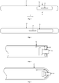
- a relative position between the film sensor and the housing may be defined in any of following manners as depicted in Figs. 7-9 .
- Fig. 7 is a schematic diagram illustrating a portion of a housing and a film sensor according to exemplary embodiments of the present disclosure.
- an inner wall of the housing 31 is provided with a locating rod g1
- the film sensor 34 that is, the fingerprint sensor
- a locating hole not shown in Fig. 7
- the locating rod g1 passes through the locating hole.
- a position of the film sensor 34 on the inner wall of the housing 31 may be limited by the locating rod g1, such that the film sensor 34 may be provided on the housing 31 at a predefined position.
- Fig. 8 depicts another way of defining the relative position between the film sensor and the housing according to exemplary embodiments of the present disclosure.
- an inner wall of the housing 31 is provided with a blind hole (not shown in Fig. 8 )
- the film sensor 34 is provided with a protuberance g2
- the protuberance g2 is located in the blind hole.
- Such a structure may also limit the position of the film sensor 34 in the inner wall of the housing 31.
- Fig.9 depicts another way of defining the relative position between the film sensor and the housing according to exemplary embodiments of the present disclosure.
- an inner wall of the housing 31 is provided with an accommodating groove (not shown in Fig. 9 ), and the film sensor 34 is provided in the accommodating groove.
- Such a structure may also limit the position of the film sensor 34 in the inner wall of the housing 31.
- an adhesive film may be provided between the film sensor and the inner wall of the housing.
- the adhesive film may include adhesive material such as thermosetting glue, water glue, solid film and PVDF (Polyvinylidene Fluoride).
- the fingerprint sensor may include an ultrasonic fingerprint sensor.
- the ultrasonic fingerprint sensor may be configured to transmit ultrasonic waves and receive ultrasonic waves. After the ultrasonic transmitted by the ultrasonic fingerprint sensor passes through the adhesive film and the housing, reflection and incidence may happen at the skin of the user's finger, allowing the ultrasonic reflected to pass through the housing and the adhesive layer and be received by the ultrasonic fingerprint sensor. The terminal may then restore the fingerprint parameter of the user according to the ultrasonic wave received.
- Fig. 10 is a schematic diagram illustrating a film sensor and a substrate in a terminal according to exemplary embodiments of the present disclosure. As illustrated in Fig. 10 , a side of the film sensor 341 away from the housing 31 is provided with a substrate 342. The substrate may support and protect the film sensor.
- the side of the film sensor 341 away from the housing 31 may not be provided with the substrate, which is not limited by the present disclosure.
- the side of the housing is made of metal, plastic or glass. In some embodiments, the side of the housing may be a part of a frame of the terminal. In some embodiments, the frame of the terminal may be a metal frame, a plastic frame or a glass frame. When the frame is a metal frame, the metal frame may be made of magnesium, aluminum, magnesium aluminum alloy or 304 stainless steel.
- Fig. 11 is a schematic diagram illustrating a terminal according to exemplary embodiments of the present disclosure. As illustrated in Fig. 11 , the terminal may further include a connected main board 35 and a fingerprint sensor control IC (integrated circuit) 36.
- IC integrated circuit
- the fingerprint sensor control IC 36 may be connected with the fingerprint sensor 34.
- the fingerprint sensor control IC 36 may be provided on an FPC (Flexible Printed Circuit) 361, and the fingerprint sensor control IC 36 may establish an electronic connection with the fingerprint sensor 34 and the main board 35 via the FPC 361.
- FPC Flexible Printed Circuit
- the FPC 361 may be connected with a BTB Connector (Board-to-board Connector) 351.
- the BTB Connector 351 may connect FPC 361 with the main board 35.
- the physical button 33 may be in contact with a dome switch 331 in the housing 31, and the dome switch 331 may be in contact with a mechanical stopper 332.
- the dome switch 3331 may act as a trigger switch. When the physical button 33 squeezes the dome switch 331, the trigger switch may be switched on, and the dome switch 331 may be connected with the main board 35 (not shown in Fig. 11 ), such that a signal triggered by the physical button 33 may be transmitted to the main board 35.
- the mechanical stopper 332 may be configured as a support structure of the dome switch 331.
- the user may touch the fingerprint recognition region simultaneously when clicking the physical button.
- Fig. 12 is a flow chart illustrating a method for controlling a terminal according to exemplary embodiments of the present disclosure. The method may be applied to a processor of any terminal illustrated in the foregoing embodiments, and the method for controlling the terminal includes the following blocks.
- fingerprint parameter collection may be performed by the fingerprint recognition region when the physical button is triggered.
- the processor may perform the fingerprint parameter collection using the fingerprint recognition region.
- the collection procedure may succeed, but may also fail due to problems such as mistaken touch and mistaken contact position of the finger.
- the processor may close or turn off the fingerprint sensor to reduce power consumption.
- an interrupt signal may be transmitted to the processor.
- the processor may interrupt the current process based on the interrupt signal, and determine that the preset condition is satisfied.
- the processor may then perform the step of collecting the fingerprint parameter using the fingerprint recognition region.
- the physical button may be a power button, and when the user presses the power button, the terminal may start to perform fingerprint recognition to unlock the terminal, which simplifies operation steps and improves the user experience.
- the processor may include one or more CPUs (Central Processing Units).
- CPUs Central Processing Units
- recognition is performed on the fingerprint parameter collected when the fingerprint parameter is collected successfully.
- Procedures of the fingerprint parameter recognition may include procedures such as extracting detailed feature points in the fingerprint parameters. Then the terminal may store the fingerprint parameters and compare the fingerprint parameters with the parameters historically stored in the terminal. When the comparison is successful, the processor may unlock the terminal.
- the fingerprint parameter collection may be performed by the fingerprint recognition region when the physical button is triggered, and the recognition may be performed on the fingerprint parameter collected when the fingerprint parameter is collected successfully.
- embodiments of the present disclosure further provide another method for controlling a terminal, and the method may include the following steps.
- fingerprint detection may be performed by the fingerprint recognition region at a first frequency.
- the first frequency may be a lower frequency. That is, the fingerprint sensor may be configured to work in a low power mode. In this mode, the processor may merely determine whether a finger presses the fingerprint recognition region.
- the processor may perform fingerprint recognition at a second frequency.
- the second frequency may be greater than the first frequency.
- the second frequency may be a work frequency at which the fingerprint recognition is normally performed in the fingerprint recognition region.
- the fingerprint detection may be performed in the low power mode, i.e., to determine whether there is the finger pressing the fingerprint recognition region.
- the fingerprint recognition may be performed at a normal work frequency, which may also achieve an effect of reducing the power consumption.
- step three recognition may be performed on the fingerprint parameter collected when the fingerprint parameter is collected successfully.
- Fig. 13 is a flow chart illustrating a method for manufacturing a terminal provided by exemplary embodiments of the present disclosure.
- the method may be configured to manufacture the terminal provided by foregoing embodiments.
- the method may include the following blocks.
- a housing may be provided.
- a side of the housing may provide a button hole.
- a physical button may be provided at the button hole.
- a fingerprint recognition region surrounding the button hole may be provided on the side of the housing.
- the user may touch the fingerprint recognition region simultaneously when clicking the physical button.
- the foregoing block 303 may include the following sub blocks.
- a film sensor may be prepared.
- the film sensor may be tailored into a preset shape by a die cutting process.
- the tailored film sensor may be bound to a FPCB (Flexible Printed Circuit Board) with a pattern.
- FPCB Flexible Printed Circuit Board
- the FPCB with the pattern may include an insulated substrate and a conductive layer, and there may be binder between the insulated substrate and the conductive layer. Bonding is a common wiring method used by those skilled in the art.
- the FPCB with the pattern may be connected to the main board.
- the FPCB may be connected with the main board by a wire bonding process or ACF (Anisotropic Conductive Film).
- the connective position between the FPCB with the pattern and the main board may be protected by coating gel.
- a fingerprint sensor control IC may be connected with the tailored film sensor and the main board.
- the fingerprint sensor control IC may be provided on the FPCB.
- the fingerprint sensor control IC may be connected with the tailored film sensor and the main board via a circuit on the FPCB.
- the fingerprint sensor control IC may be directly provided on the main board (for example, the film sensor is provided on the FPCB or the main board by a SMT (Surface Mount Technology)), and the fingerprint sensor control IC may be connected with the tailored film sensor by the circuit on the FPCB.
- one or more inspection steps may be performed to determine whether the film sensor can work normally. If the film sensor can work normally, subsequent operations may be performed. IF the film sensor cannot work normally, trouble diagnosis and troubleshooting may be performed.
- the tailored film sensor may be attached to an inner wall of a side of the housing.
- a region where a front projection of the film sensor on an outer wall of the housing is located is considered/recognized as the fingerprint recognition region.
- sub block 3036 may include the following process steps.
- an adhesive film may be tailored into the preset shape by a die cutting process, in which each of two sides of the adhesive film is provided with a protective film.
- the protective film on one side of the adhesive film may be removed, and the adhesive film may be attached to the tailored film sensor.
- the protective film on the other side of the adhesive film may be removed, and the adhesive film may be attached to the inner wall of the side of the housing.
- the adhesive film may be hardened by a hardening process.
- the hardening process may include pressing and heating, etc.
- a confirmation step may be carried out to confirm whether the film sensor is firmly attached to the housing.
- the user may touch the fingerprint recognition region simultaneously when clicking the physical button.
- Fig. 15 is a block diagram illustrating a terminal 800 according to exemplary embodiments.
- the terminal 800 may be a mobile phone, a computer, a digital broadcast terminal, an information transmitting and receiving device, a gaming console, a tablet device, a medical equipment, a fitness facility, a personal digital assistant and the like.
- the terminal 800 may include one or more components of: a processing component 802, a memory 804, a power component 806, a multimedia component 808, an audio component 810, an I/O (Input/ Output) interface 812, a sensor component 814, a communication component 816.
- the processing component 802 usually controls overall operation of the terminal 800, such as operations associated with display, telephone calls, data communications, camera operations, and recording operations.
- the processing component 802 may include one or more processors 820 to execute instructions, to complete all or part of the operations in the above described methods.
- the processing component 802 may include one or more modules which facilitate interaction between the processing component 802 and other components.
- the processing component 802 may include a multimedia module to facilitate interaction between the multimedia component 808 and the processing component 802.
- the memory 804 is configured to store various types of data to support operations at the terminal 800. Examples of such data include instructions for any applications or methods operated on the terminal 800, contact data, phonebook data, messages, pictures, videos, etc.
- the memory 804 may be implemented using any type of volatile or non-volatile storage devices, or a combination thereof, such as a static random access memory (SRAM), an electrically erasable programmable read-only memory (EEPROM), an erasable programmable read-only memory (EPROM), a programmable read-only memory (PROM), a read-only memory (ROM), a magnetic memory, a flash memory, a magnetic or optical disk.
- SRAM static random access memory
- EEPROM electrically erasable programmable read-only memory
- EPROM erasable programmable read-only memory
- PROM programmable read-only memory
- ROM read-only memory
- magnetic memory a magnetic memory
- flash memory a flash memory
- magnetic or optical disk a magnetic or optical disk
- the power component 806 provides power to various components of the terminal 800.
- the power component 806 may include a power management system, one or more power supplies, and other components related to generation, management, and distribution of power in the terminal 800.
- the multimedia component 808 includes a screen that provides an output interface between the terminal 800 and the user.
- the screen may include a liquid crystal display (LCD) and a touch panel (TP). If the screen includes the touch panel, the screen may be implemented as a touch screen to receive input signals from the user.
- the touch panel includes one or more touch sensors to sense touches, swipes, and gestures on the touch panel. The touch sensors may not only sense a boundary of a touch or swipe action, but also sense a duration and a pressure associated with the touch or swipe action.
- the multimedia component 808 includes a front camera and/or a rear camera. When the terminal 800 is in an operation mode such as a photographing mode or a video mode, the front camera and/or the rear camera may receive external multimedia data. Each of the front and rear cameras may be a fixed optical lens system or have a focus and optical zoom capability.
- the audio component 810 is configured to output and/or input audio signals.
- the audio component 810 includes a microphone (MIC) configured to receive an external audio signal when the terminal 800 is in an operating mode, such as a call mode, a recording mode, and a speech recognition mode.
- the received audio signal may be further stored in the memory 804 or transmitted via the communication component 816.
- the audio component 810 may further include a speaker, which is configured to input an audio signal.
- the I/O interface 812 provides an interface between the processing component 802 and a peripheral interface module, such as a keyboard, a click wheel, a button and the like.
- a peripheral interface module such as a keyboard, a click wheel, a button and the like.
- the buttons may include, but are not limited to, a home button, a volume button, a starting button, and a locking button.
- the sensor component 814 includes one or more sensors for providing status assessments of various aspects of the terminal 800.
- the sensor component 814 may detect an open/closed state of the terminal 800, relative positioning of the components, such as the display and the keypad, of the terminal 800, a change in position of the terminal 800 or of a component of the terminal 800, presence or absence of user contact with that terminal 800, an orientation or an acceleration/deceleration of the terminal 800, and a change in temperature of the terminal 800.
- the sensor component 814 may include a proximity sensor configured to detect the presence of nearby objects without any physical contact.
- the sensor component 814 may also include a light sensor, such as a CMOS or CCD image sensor, for use in imaging applications.
- the sensor component 814 may also include an accelerometer sensor, a gyroscope sensor, a magnetic sensor, a pressure sensor, or a temperature sensor.
- the communication component 816 is configured to facilitate wired or wireless communication between the terminal 800 and other devices.
- the terminal 800 can access a wireless network based on a communication standard, such as WiFi, 2G, or 3G, or a combination of them.
- the communication component 816 receives a broadcast signal or broadcast related information from an external broadcast management system via a broadcast channel.
- the communication component 816 further includes a near field communication (NFC) module to facilitate short-range communication.
- the NFC module may be implemented based on a radio frequency identification (RFID) technology, an infrared data association (IrDA) technology, an ultra-wideband (UWB) technology, a Bluetooth (BT) technology, and other technologies.
- RFID radio frequency identification
- IrDA infrared data association
- UWB ultra-wideband
- BT Bluetooth
- the terminal 800 may be implemented with one or more application specific integrated circuits (ASICs), digital signal processors (DSPs), digital signal processing devices (DSPDs), programmable logic devices (PLDs), field programmable gate arrays (FPGAs), controllers, micro-controllers, microprocessors, or other electronic components, for performing the methods described above.
- ASICs application specific integrated circuits
- DSPs digital signal processors
- DSPDs digital signal processing devices
- PLDs programmable logic devices
- FPGAs field programmable gate arrays
- controllers micro-controllers, microprocessors, or other electronic components, for performing the methods described above.
- non-transitory computer readable storage medium including instructions, such as the memory 804 including instructions.
- the instructions can be executed by the processor 820 of the terminal 800 to complete technical processing executed by the processor in the foregoing embodiments.
- the non-transitory computer readable storage medium may be a read only memory (ROM), a random access memory (RAM), a compact disk- read only memory (CD-ROM), a magnetic tape, a floppy disk, an optical data storage device, and the like.
- a computer-readable storage medium may include a non-volatile computer-readable storage medium.
- the computer-readable storage medium may be stored with computer programs.
- the programs may be configured to be executed by a processor to realize a method for controlling a terminal provided by embodiments of the present disclosure.
- the method may include:
Landscapes
- Engineering & Computer Science (AREA)
- Theoretical Computer Science (AREA)
- Physics & Mathematics (AREA)
- General Physics & Mathematics (AREA)
- General Engineering & Computer Science (AREA)
- Human Computer Interaction (AREA)
- Multimedia (AREA)
- Computer Security & Cryptography (AREA)
- Signal Processing (AREA)
- Microelectronics & Electronic Packaging (AREA)
- Bioinformatics & Cheminformatics (AREA)
- Evolutionary Biology (AREA)
- Data Mining & Analysis (AREA)
- Computer Vision & Pattern Recognition (AREA)
- Bioinformatics & Computational Biology (AREA)
- Life Sciences & Earth Sciences (AREA)
- Evolutionary Computation (AREA)
- Computer Hardware Design (AREA)
- Software Systems (AREA)
- Artificial Intelligence (AREA)
- Telephone Function (AREA)
- Telephone Set Structure (AREA)
- Image Input (AREA)
Abstract
Description
- The present disclosure relates to a field of mobile technology, and more particularly to a terminal, a method for controlling a terminal, a method for manufacturing a terminal, and a storage medium.
- Terminals have become indispensable electronic product in people's lives. Various terminals such as mobile phones, tablet computers and notebook computers greatly increase convenience of people's lives.
- Some terminal may be configured with unlocking mechanisms. Such a terminal may include, for example, a housing, a fingerprint recognition region provided in the housing, and some physical buttons. When a user wants to unlock the terminal, the physical button may be clicked to wake up the terminal (for example, when the terminal is provided with a display screen, the display screen may be lighted up by clicking the physical button), and then the fingerprint recognition region is touched to unlock the terminal.
- However, these steps of unlocking the terminal by the user are relatively cumbersome.
- Embodiments of the present disclosure provide a terminal, a method for controlling a terminal, a method for manufacturing a terminal and a storage medium, which may solve a problem in the related art that steps of unlocking the terminal by the user are relatively cumbersome.
- According to a first aspect of the present invention, a terminal is provided. The terminal may include a housing. A side of the housing may have a button hole. A physical button may be provided at the button hole. The side of the housing may be further provided with a fingerprint recognition region surrounding the button hole.
- In some embodiments, a fingerprint sensor may be provided in the housing. A region where a front projection of the fingerprint sensor on an outer wall of the housing is located is the fingerprint recognition region.
- In some embodiments, the fingerprint sensor may be a film sensor attached to an inner wall of the housing.
- In some embodiments, the inner wall of the housing may be provided with a locating rod, the film sensor may be provided with a locating hole, and the locating rod may pass through the locating hole.
- In other embodiments, the inner wall of the housing may be provided with a blind hole, the film sensor may be provided with a protuberance, and the protuberance may be located in the blind hole.
- In yet other embodiments, the inner wall of the housing may be provided with an accommodating groove, and the film sensor may be provided in the accommodating groove.
- In some embodiments, the terminal may further include a substrate. The substrate may be configured to support a side of the film sensor facing away from the housing.
- In some embodiments, the side of the housing may have a protruded curved surface.
- In some embodiments, the side of the housing may be made of metal, plastic or glass.
- In some embodiments, the terminal may further include a connected main board and a fingerprint sensor control integrated circuit. The fingerprint sensor control integrated circuit may be connected with the fingerprint sensor.
- In some embodiments, an area of the fingerprint recognition region may be greater than an area of a region surrounded by the fingerprint recognition region.
- In some embodiments, the fingerprint sensor may include a plurality of sub sensors arranged in an array.
- According to a second aspect of the present invention, a method for controlling a terminal is provided. The terminal may include a housing. A side of the housing may be provided with a button hole. A physical button may be provided at the button hole. The side of the housing may be further provided with a fingerprint recognition region surrounding the button hole. The method may include:
- performing fingerprint parameter collection by the fingerprint recognition region when the physical button is triggered;
- performing recognition on a fingerprint parameter collected when the fingerprint parameter is collected successfully.
- According to a third aspect of the present invention, a method for manufacturing a terminal is provided. The method may include:
- providing a housing, a side of the housing having a button hole;
- providing a physical button at the button hole; and
- providing a fingerprint recognition region surrounding the button hole on the side of the housing.
- In some embodiments, the method may further include providing a main board in the housing, and providing the fingerprint recognition region surrounding the button hole on the side face of the housing may include:
- preparing a film sensor;
- tailoring the film sensor into a preset shape by a die cutting process;
- binding the tailored film sensor to a flexible printed circuit board with a pattern;
- connecting the flexible printed circuit board with the pattern to the main board;
- connecting a fingerprint sensor control integrated circuit with the tailored film sensor and the main board; and
- attaching the tailored film sensor to an inner wall of the side of the housing, so that a region where a front projection of the film sensor on an outer wall of the housing is located is the fingerprint recognition region.
- In some embodiments, attaching the tailored film sensor to the inner wall of the side of the housing may include:
- tailoring an adhesive film into the preset shape by the die cutting process, each of two sides of the adhesive film being provided with a protective film;
- removing the protective film on one side of the adhesive film, and attaching the adhesive film to the tailored film sensor;
- removing the protective film on the other side of the adhesive film, and attaching the adhesive film to the inner wall of the side of the housing; and
- hardening the adhesive film by a hardening process.
- According to a fourth aspect of the present invention, a terminal is provided. The terminal may include a processor, a memory, and a housing. The memory may be configured to store instructions executable by the processor. A side of the housing may be provided with a button hole. A physical button may be provided at the button hole. The side of the housing may be further provided with a fingerprint recognition region surrounding the button hole. The processor may be configured to: perform fingerprint parameter collection by the fingerprint recognition region when a preset condition is satisfied; and perform recognition on a fingerprint parameter collected when the fingerprint parameter is collected successfully.
- According to a fifth aspect of the present invention, a storage medium is provided. The storage medium may be stored with at least one instruction, and the at least one instruction may be configured to be loaded and executed by a processor to implement a method for controlling a terminal according to the second aspect.
- Beneficial effects brought by the technical solutions provided by embodiments of the present disclosure are as follows.
- The fingerprint recognition region is combined with a region occupied by the physical button, such that the user may touch the fingerprint recognition region simultaneously when clicking the physical button. A problem in the related art that steps of unlocking a terminal by the user are relatively cumbersome is solved, and an effect that steps of unlocking the terminal by the user are simplified is achieved.
- The accompanying drawings, which are incorporated in and constitute a part of the specification, illustrate embodiments consistent with the present disclosure and serve to explain the principles of the present disclosure together with the specification.
-
Fig. 1 is a schematic diagram illustrating a traditional terminal; -
Fig. 2 is a schematic diagram illustrating another traditional terminal; -
Fig. 3 is a schematic diagram illustrating a terminal according to exemplary embodiments of the present disclosure; -
Fig. 4 is a schematic diagram illustrating another terminal according to exemplary embodiments of the present disclosure; -
Fig. 5 is a sectional view of the terminal illustrated inFig. 3 ; -
Fig. 6 is a schematic diagram illustrating another terminal according to exemplary embodiments of the present disclosure; -
Fig. 7 is a schematic diagram illustrating a portion of a housing and a film sensor in a terminal according to exemplary embodiments of the present disclosure; -
Fig. 8 is a schematic diagram illustrating a portion of a housing and a film sensor in another terminal according to exemplary embodiments of the present disclosure; -
Fig. 9 is a schematic diagram illustrating a portion of a housing and a film sensor in another terminal according to exemplary embodiments of the present disclosure; -
Fig. 10 is a schematic diagram illustrating a film sensor and a substrate in a terminal according to exemplary embodiments of the present disclosure; -
Fig. 11 is a schematic diagram illustrating another terminal according to exemplary embodiments of the present disclosure; -
Fig. 12 is a flow chart illustrating a method for controlling a terminal according to exemplary embodiments of the present disclosure; -
Fig. 13 is a flow chart illustrating a method for manufacturing a terminal according to exemplary embodiments of the present disclosure; -
Fig. 14 is a flow chart illustrating a method for providing a fingerprint recognition region illustrated inFig. 13 ; and -
Fig. 15 is a schematic diagram illustrating a terminal according to embodiments of the present disclosure. - Exemplary embodiments will be described in detail herein, examples of which are illustrated in the accompanying drawings. The following description refers to the accompanying drawings in which the same numbers in different drawings represent the same or similar elements unless otherwise represented. The implementations set forth in the following description of exemplary embodiments do not represent all implementations consistent with the present disclosure. Instead, they are merely examples of devices and methods consistent with some aspects related to the present disclosure as detailed in the appended claims.
- At present, housings of various terminals such as mobile phones and tablet computers are usually in a plate shape, and one of two planar surfaces in the plate-shaped housing may be provided with a display screen. A fingerprint recognition region may be provided in manners depicted in
Figs. 1 and 2 . -
Fig. 1 is a schematic diagram illustrating a traditional terminal in which the fingerprint recognition region is provided on a front surface of the housing provided with the display screen. - As illustrated in
Fig. 1 , afingerprint recognition region 12 and adisplay device 13 are provided on the same surface of thehousing 11. It may be seen that, after a user clicks a physical button (for example, when the user holds the terminal with one hand, and clicks the physical button on the surface of the terminal with a thumb), it may be more difficult for the user to touch thefingerprint recognition region 12. In addition, existence of thefingerprint recognition region 12 may severely reduce a screen-to-body ratio of the terminal (the screen-to-body ratio may be a radio between an area of the display screen and an area of the surface of the terminal where the display screen is located). - In addition, as illustrated in
Fig. 1 , thefingerprint recognition region 12 provided at the bottom of thedisplay screen 13 may further interfere with other components in the terminal such as an antenna component, which increases difficulty in providing thefingerprint recognition region 12. -
Fig. 2 is a schematic diagram illustrating a tradition terminal in which the fingerprint recognition region is provided on a back surface of the housing which is opposite to the display screen. - As illustrated in
Fig. 2 , thefingerprint recognition region 12 and the display device are provided on opposite surfaces of thehousing 11. It may be seen that, after the user clicks the physical button (for example, when the user holds the terminal with one hand, and clicks the physical button on the surface of the terminal by the thumb), it may be difficult for the user to touch thefingerprint recognition region 12. - In addition, the back surface of the
housing 11 which is opposite to the display screen is usually provided with acamera 14. Thefingerprint recognition region 12 may conflict with an area where thecamera 14 is located, and may occupy space where a battery in the housing is disposed. - Embodiments of the present disclosure provide terminals and methods for controlling terminals without the aforementioned shortcomings.
-
Fig. 3 is a schematic diagram illustrating a terminal according to exemplary embodiments of the present disclosure. The terminal may include ahousing 31. - A side of the
housing 31 may have a button hole (not shown inFig. 3 ), and aphysical button 33 may be provided at the button hole. - The side of the
housing 31 may be further provided with afingerprint recognition region 32 surrounding the button hole. - With the terminal provided by embodiments of the present disclosure, by combining the fingerprint recognition region with the region occupied by the physical button, the user may touch the fingerprint recognition region simultaneously when clicking the physical button. The aforementioned shortcomings associated with unlocking the terminal are solved, and the steps required to unlock the terminal are simplified.
- In addition, as illustrated in
Fig. 4 , when thephysical button 33 and thefingerprint recognition region 32 are independently provided in thehousing 31, a larger area of the housing will be occupied. However, in the terminal provided by embodiments of the present disclosure illustrated inFig. 3 , the fingerprint recognition region and the physical button are combined, which reduces the area of the housing occupied by the fingerprint recognition region and the physical button. -
Fig. 5 is a cross-sectional view of the terminal illustrated inFig. 3 along A-A. - In some embodiments, a
fingerprint sensor 34 is provided in thehousing 31. - In some embodiments, a region where a front projection of the
fingerprint sensor 34 on an outer wall of thehousing 31 is located is thefingerprint recognition region 32. - In some embodiments, the
fingerprint sensor 34 may be an ultrasonic fingerprint sensor or an optical fingerprint sensor. When thefingerprint sensor 34 is the optical fingerprint sensor, the side of thehousing 31 is made of transparent material. - In some embodiments, the
fingerprint sensor 34 may be a film sensor. The film sensor is attached to an inner wall of thehousing 31. A thickness of the film sensor may be between 0.1mm and 0.2mm. The film sensor may be flexible, which facilitates to be attached to the inner wall of thehousing 31. - In some embodiments, the
physical button 33 passes through thefingerprint sensor 34 and the button hole in thehousing 31 to extend out of thehousing 31, which facilitates the user to press thephysical button 33. Thephysical button 33 may be a power button, a volume adjustment button, a customizable button or any other function button. - In some embodiments, the
fingerprint sensor 34 is provided in thehousing 31, such that thehousing 31 may protect thefingerprint sensor 34. However, thefingerprint sensor 34 may further be provided on an outer wall of the housing, which is not limited by embodiments of the present disclosure. - In some embodiments, the
housing 31 is in a rectangular plate shape, and thefingerprint recognition region 32 is provided on the side of thehousing 31. - In some embodiments, the
fingerprint recognition region 32 is provided on the side of thehousing 31 that is generally perpendicular to two larger sides of the rectangular plate. - In some embodiments, the
fingerprint recognition region 32 provided on the side of thehousing 31 may not occupy two lager sides of thehousing 31 configured to be provided with the display screen and the camera, which reserves sufficient space for the display screen and the camera. - In some embodiments, as illustrated in
Fig.3 , an area occupied by thefingerprint recognition region 32 on the side of thehousing 31 is greater than an area occupied by thephysical button 33 on the side of thehousing 31. In this manner, the area of thefingerprint recognition region 32 may be increased, which may improve a success rate of fingerprint recognition. - For example, a thickness of a
housing 31 may be 8mm, the length of thefingerprint recognition region 32 in the thickness direction of thehousing 31 may be 6 mm, the length of thefingerprint recognition region 32 in a length direction f of the side of the housing may be 18mm, the length of thephysical button 33 in the thickness direction of thehousing 31 may be 2mm, and the length of thephysical button 33 in the length direction f may be 12mm. -
Fig. 6 is a schematic diagram illustrating a terminal according to exemplary embodiments of the present disclosure. As illustrated inFig. 6 , the side of thehousing 31 of the terminal may have a protruded curved surface. Furthermore, the front projection of thefingerprint sensor 34 on this side may also be included in thefingerprint recognition region 32. In this manner, the area of thefingerprint recognition region 32 may be increased, which may improve the success rate of fingerprint recognition. - It is noted that it may be difficult to bend fingerprint sensors implemented based on silicon-based technology. Thus, when the side of the housing is provided with the sensor based on the silicon-based technology, an area of the sensor based on the silicon-based technology is usually smaller, and the success rate of the fingerprint recognition is not high. However, in some embodiments of the present disclosure, the film sensor based on the fingerprint recognition technology is taken as the fingerprint sensor, such that the fingerprint sensor may bend with the side of the housing, which increases the area of the fingerprint recognition region and improves the success rate of the fingerprint recognition.
- In some embodiments, the
fingerprint sensor 34 may include a plurality of sub-sensors arranged in an array. The plurality of sub-sensors may respectively perform fingerprint parameter collection. Fingerprint parameters collected by the plurality of sub-sensors may be gathered. In this manner, when one or more sub-sensors fail or do not collect fingerprint parameters, the terminal may still collect the fingerprint parameters of the user, which may improve the success rate of fingerprint recognition. - In addition, the
fingerprint sensor 34 may be a single sensor, which is not limited by embodiments of the present disclosure. - In some terminal configured in accordance with embodiments of the present disclosure, a relative position between the film sensor and the housing may be defined in any of following manners as depicted in
Figs. 7-9 . -
Fig. 7 is a schematic diagram illustrating a portion of a housing and a film sensor according to exemplary embodiments of the present disclosure. As illustrated inFig. 7 , an inner wall of thehousing 31 is provided with a locating rod g1, the film sensor 34 (that is, the fingerprint sensor) is provided with a locating hole (not shown inFig. 7 ), and the locating rod g1 passes through the locating hole. In this way, a position of thefilm sensor 34 on the inner wall of thehousing 31 may be limited by the locating rod g1, such that thefilm sensor 34 may be provided on thehousing 31 at a predefined position. -
Fig. 8 depicts another way of defining the relative position between the film sensor and the housing according to exemplary embodiments of the present disclosure. As illustrated inFig. 8 , an inner wall of thehousing 31 is provided with a blind hole (not shown inFig. 8 ), thefilm sensor 34 is provided with a protuberance g2, and the protuberance g2 is located in the blind hole. Such a structure may also limit the position of thefilm sensor 34 in the inner wall of thehousing 31. -
Fig.9 depicts another way of defining the relative position between the film sensor and the housing according to exemplary embodiments of the present disclosure. As illustrated inFig. 9 , an inner wall of thehousing 31 is provided with an accommodating groove (not shown inFig. 9 ), and thefilm sensor 34 is provided in the accommodating groove. Such a structure may also limit the position of thefilm sensor 34 in the inner wall of thehousing 31. - In addition, an adhesive film may be provided between the film sensor and the inner wall of the housing. The adhesive film may include adhesive material such as thermosetting glue, water glue, solid film and PVDF (Polyvinylidene Fluoride).
- The fingerprint sensor may include an ultrasonic fingerprint sensor. When the fingerprint sensor is an ultrasonic fingerprint sensor, the ultrasonic fingerprint sensor may be configured to transmit ultrasonic waves and receive ultrasonic waves. After the ultrasonic transmitted by the ultrasonic fingerprint sensor passes through the adhesive film and the housing, reflection and incidence may happen at the skin of the user's finger, allowing the ultrasonic reflected to pass through the housing and the adhesive layer and be received by the ultrasonic fingerprint sensor. The terminal may then restore the fingerprint parameter of the user according to the ultrasonic wave received.
-
Fig. 10 is a schematic diagram illustrating a film sensor and a substrate in a terminal according to exemplary embodiments of the present disclosure. As illustrated inFig. 10 , a side of thefilm sensor 341 away from thehousing 31 is provided with asubstrate 342. The substrate may support and protect the film sensor. - In addition, the side of the
film sensor 341 away from thehousing 31 may not be provided with the substrate, which is not limited by the present disclosure. - In some embodiments, the side of the housing is made of metal, plastic or glass. In some embodiments, the side of the housing may be a part of a frame of the terminal. In some embodiments, the frame of the terminal may be a metal frame, a plastic frame or a glass frame. When the frame is a metal frame, the metal frame may be made of magnesium, aluminum, magnesium aluminum alloy or 304 stainless steel.
-
Fig. 11 is a schematic diagram illustrating a terminal according to exemplary embodiments of the present disclosure. As illustrated inFig. 11 , the terminal may further include a connectedmain board 35 and a fingerprint sensor control IC (integrated circuit) 36. - The fingerprint
sensor control IC 36 may be connected with thefingerprint sensor 34. In some embodiments, the fingerprintsensor control IC 36 may be provided on an FPC (Flexible Printed Circuit) 361, and the fingerprintsensor control IC 36 may establish an electronic connection with thefingerprint sensor 34 and themain board 35 via theFPC 361. - In some embodiments, the
FPC 361 may be connected with a BTB Connector (Board-to-board Connector) 351. TheBTB Connector 351 may connectFPC 361 with themain board 35. - In some embodiments, the
physical button 33 may be in contact with adome switch 331 in thehousing 31, and thedome switch 331 may be in contact with amechanical stopper 332. The dome switch 3331 may act as a trigger switch. When thephysical button 33 squeezes thedome switch 331, the trigger switch may be switched on, and thedome switch 331 may be connected with the main board 35 (not shown inFig. 11 ), such that a signal triggered by thephysical button 33 may be transmitted to themain board 35. Themechanical stopper 332 may be configured as a support structure of thedome switch 331. - With the terminal provided by embodiments of the present disclosure, by combining the fingerprint recognition region with the region occupied by the physical button, the user may touch the fingerprint recognition region simultaneously when clicking the physical button. The aforementioned shortcomings associated with unlocking a terminal are solved, and steps required to unlock the terminal are simplified.
-
Fig. 12 is a flow chart illustrating a method for controlling a terminal according to exemplary embodiments of the present disclosure. The method may be applied to a processor of any terminal illustrated in the foregoing embodiments, and the method for controlling the terminal includes the following blocks. - In
block 201, fingerprint parameter collection may be performed by the fingerprint recognition region when the physical button is triggered. - When the physical button is triggered, the processor may perform the fingerprint parameter collection using the fingerprint recognition region. The collection procedure may succeed, but may also fail due to problems such as mistaken touch and mistaken contact position of the finger.
- In some embodiments, before the physical button is triggered, the processor may close or turn off the fingerprint sensor to reduce power consumption.
- In some embodiments, after the physical button is pressed, an interrupt signal may be transmitted to the processor. The processor may interrupt the current process based on the interrupt signal, and determine that the preset condition is satisfied. The processor may then perform the step of collecting the fingerprint parameter using the fingerprint recognition region.
- In some embodiments, the physical button may be a power button, and when the user presses the power button, the terminal may start to perform fingerprint recognition to unlock the terminal, which simplifies operation steps and improves the user experience.
- In some embodiments, the processor may include one or more CPUs (Central Processing Units).
- In
block 202, recognition is performed on the fingerprint parameter collected when the fingerprint parameter is collected successfully. - Procedures of the fingerprint parameter recognition may include procedures such as extracting detailed feature points in the fingerprint parameters. Then the terminal may store the fingerprint parameters and compare the fingerprint parameters with the parameters historically stored in the terminal. When the comparison is successful, the processor may unlock the terminal.
- With the method provided by embodiments of the present disclosure, the fingerprint parameter collection may be performed by the fingerprint recognition region when the physical button is triggered, and the recognition may be performed on the fingerprint parameter collected when the fingerprint parameter is collected successfully. The aforementioned shortcomings associated with unlocking the terminal are solved, and the steps required to unlock the terminal are simplified.
- In addition, embodiments of the present disclosure further provide another method for controlling a terminal, and the method may include the following steps.
- In step 1, fingerprint detection may be performed by the fingerprint recognition region at a first frequency.
- The first frequency may be a lower frequency. That is, the fingerprint sensor may be configured to work in a low power mode. In this mode, the processor may merely determine whether a finger presses the fingerprint recognition region.
- In step 2, when the finger is detected by the fingerprint recognition region, the processor may perform fingerprint recognition at a second frequency. The second frequency may be greater than the first frequency.
- The second frequency may be a work frequency at which the fingerprint recognition is normally performed in the fingerprint recognition region. In this manner, when the processor does not determine that the fingerprint recognition region is pressed by the finger, the fingerprint detection may be performed in the low power mode, i.e., to determine whether there is the finger pressing the fingerprint recognition region. When it is detected that there is the finger pressing the fingerprint recognition region, the fingerprint recognition may be performed at a normal work frequency, which may also achieve an effect of reducing the power consumption.
- In step three, recognition may be performed on the fingerprint parameter collected when the fingerprint parameter is collected successfully.
-
Fig. 13 is a flow chart illustrating a method for manufacturing a terminal provided by exemplary embodiments of the present disclosure. The method may be configured to manufacture the terminal provided by foregoing embodiments. The method may include the following blocks. - In
block 301, a housing may be provided. A side of the housing may provide a button hole. - In
block 302, a physical button may be provided at the button hole. - In
block 303, a fingerprint recognition region surrounding the button hole may be provided on the side of the housing. - With the method for manufacturing the terminal provided by embodiments of the present disclosure, by combining the fingerprint recognition region with the region occupied by the physical button, the user may touch the fingerprint recognition region simultaneously when clicking the physical button. The aforementioned shortcomings associated with unlocking the terminal are solved, and the steps required to unlock the terminal are simplified.
- In some embodiments, as illustrated in
Fig. 14 , when the fingerprint sensor is a film sensor, the foregoingblock 303 may include the following sub blocks. - In
sub block 3031, a film sensor may be prepared. - In
sub block 3032, the film sensor may be tailored into a preset shape by a die cutting process. - With respect to the preset shape, reference may be made to the
fingerprint recognition region 32 inFig. 3 . - In
sub block 3033, the tailored film sensor may be bound to a FPCB (Flexible Printed Circuit Board) with a pattern. - In some embodiments, the FPCB with the pattern may include an insulated substrate and a conductive layer, and there may be binder between the insulated substrate and the conductive layer. Bonding is a common wiring method used by those skilled in the art.
- In
sub block 3034, the FPCB with the pattern may be connected to the main board. - In some embodiments, the FPCB may be connected with the main board by a wire bonding process or ACF (Anisotropic Conductive Film).
- In some embodiments, the connective position between the FPCB with the pattern and the main board may be protected by coating gel.
- In
sub block 3035, a fingerprint sensor control IC may be connected with the tailored film sensor and the main board. - In some embodiments, the fingerprint sensor control IC may be provided on the FPCB. The fingerprint sensor control IC may be connected with the tailored film sensor and the main board via a circuit on the FPCB. In other embodiments, the fingerprint sensor control IC may be directly provided on the main board (for example, the film sensor is provided on the FPCB or the main board by a SMT (Surface Mount Technology)), and the fingerprint sensor control IC may be connected with the tailored film sensor by the circuit on the FPCB.
- In some embodiments, one or more inspection steps may be performed to determine whether the film sensor can work normally. If the film sensor can work normally, subsequent operations may be performed. IF the film sensor cannot work normally, trouble diagnosis and troubleshooting may be performed.
- In
sub block 3036, the tailored film sensor may be attached to an inner wall of a side of the housing. In some embodiments, a region where a front projection of the film sensor on an outer wall of the housing is located is considered/recognized as the fingerprint recognition region. - In some embodiments,
sub block 3036 may include the following process steps. - In a first step, an adhesive film may be tailored into the preset shape by a die cutting process, in which each of two sides of the adhesive film is provided with a protective film.
- In a second step, the protective film on one side of the adhesive film may be removed, and the adhesive film may be attached to the tailored film sensor.
- In a third step, the protective film on the other side of the adhesive film may be removed, and the adhesive film may be attached to the inner wall of the side of the housing.
- In a fourth step, the adhesive film may be hardened by a hardening process.
- The hardening process may include pressing and heating, etc. A confirmation step may be carried out to confirm whether the film sensor is firmly attached to the housing.
- With the method for manufacturing the terminal provided by embodiments of the present disclosure, by combining the fingerprint recognition region with the region occupied by the physical button, the user may touch the fingerprint recognition region simultaneously when clicking the physical button. The aforementioned shortcomings associated with unlocking a terminal are solved, and the steps required to unlock the terminal are simplified.
-
Fig. 15 is a block diagram illustrating a terminal 800 according to exemplary embodiments. For example, the terminal 800 may be a mobile phone, a computer, a digital broadcast terminal, an information transmitting and receiving device, a gaming console, a tablet device, a medical equipment, a fitness facility, a personal digital assistant and the like. - Referring to
Fig. 15 , the terminal 800 may include one or more components of: aprocessing component 802, amemory 804, apower component 806, amultimedia component 808, anaudio component 810, an I/O (Input/ Output)interface 812, asensor component 814, acommunication component 816. - The
processing component 802 usually controls overall operation of the terminal 800, such as operations associated with display, telephone calls, data communications, camera operations, and recording operations. Theprocessing component 802 may include one ormore processors 820 to execute instructions, to complete all or part of the operations in the above described methods. In addition, theprocessing component 802 may include one or more modules which facilitate interaction between theprocessing component 802 and other components. For instance, theprocessing component 802 may include a multimedia module to facilitate interaction between themultimedia component 808 and theprocessing component 802. - The
memory 804 is configured to store various types of data to support operations at the terminal 800. Examples of such data include instructions for any applications or methods operated on the terminal 800, contact data, phonebook data, messages, pictures, videos, etc. Thememory 804 may be implemented using any type of volatile or non-volatile storage devices, or a combination thereof, such as a static random access memory (SRAM), an electrically erasable programmable read-only memory (EEPROM), an erasable programmable read-only memory (EPROM), a programmable read-only memory (PROM), a read-only memory (ROM), a magnetic memory, a flash memory, a magnetic or optical disk. - The
power component 806 provides power to various components of the terminal 800. Thepower component 806 may include a power management system, one or more power supplies, and other components related to generation, management, and distribution of power in theterminal 800. - The
multimedia component 808 includes a screen that provides an output interface between the terminal 800 and the user. In some embodiments, the screen may include a liquid crystal display (LCD) and a touch panel (TP). If the screen includes the touch panel, the screen may be implemented as a touch screen to receive input signals from the user. The touch panel includes one or more touch sensors to sense touches, swipes, and gestures on the touch panel. The touch sensors may not only sense a boundary of a touch or swipe action, but also sense a duration and a pressure associated with the touch or swipe action. In some embodiments, themultimedia component 808 includes a front camera and/or a rear camera. When the terminal 800 is in an operation mode such as a photographing mode or a video mode, the front camera and/or the rear camera may receive external multimedia data. Each of the front and rear cameras may be a fixed optical lens system or have a focus and optical zoom capability. - The
audio component 810 is configured to output and/or input audio signals. For example, theaudio component 810 includes a microphone (MIC) configured to receive an external audio signal when the terminal 800 is in an operating mode, such as a call mode, a recording mode, and a speech recognition mode. The received audio signal may be further stored in thememory 804 or transmitted via thecommunication component 816. In some embodiments, theaudio component 810 may further include a speaker, which is configured to input an audio signal. - The I/
O interface 812 provides an interface between theprocessing component 802 and a peripheral interface module, such as a keyboard, a click wheel, a button and the like. The buttons may include, but are not limited to, a home button, a volume button, a starting button, and a locking button. - The
sensor component 814 includes one or more sensors for providing status assessments of various aspects of the terminal 800. For example, thesensor component 814 may detect an open/closed state of the terminal 800, relative positioning of the components, such as the display and the keypad, of the terminal 800, a change in position of the terminal 800 or of a component of the terminal 800, presence or absence of user contact with that terminal 800, an orientation or an acceleration/deceleration of the terminal 800, and a change in temperature of the terminal 800. Thesensor component 814 may include a proximity sensor configured to detect the presence of nearby objects without any physical contact. Thesensor component 814 may also include a light sensor, such as a CMOS or CCD image sensor, for use in imaging applications. In some embodiments, thesensor component 814 may also include an accelerometer sensor, a gyroscope sensor, a magnetic sensor, a pressure sensor, or a temperature sensor. - The
communication component 816 is configured to facilitate wired or wireless communication between the terminal 800 and other devices. The terminal 800 can access a wireless network based on a communication standard, such as WiFi, 2G, or 3G, or a combination of them. In an exemplary embodiment, thecommunication component 816 receives a broadcast signal or broadcast related information from an external broadcast management system via a broadcast channel. In an exemplary embodiment, thecommunication component 816 further includes a near field communication (NFC) module to facilitate short-range communication. For example, the NFC module may be implemented based on a radio frequency identification (RFID) technology, an infrared data association (IrDA) technology, an ultra-wideband (UWB) technology, a Bluetooth (BT) technology, and other technologies. - In exemplary embodiments, the terminal 800 may be implemented with one or more application specific integrated circuits (ASICs), digital signal processors (DSPs), digital signal processing devices (DSPDs), programmable logic devices (PLDs), field programmable gate arrays (FPGAs), controllers, micro-controllers, microprocessors, or other electronic components, for performing the methods described above.
- In exemplary embodiments, there is also provided a non-transitory computer readable storage medium including instructions, such as the
memory 804 including instructions. The instructions can be executed by theprocessor 820 of the terminal 800 to complete technical processing executed by the processor in the foregoing embodiments. For example, the non-transitory computer readable storage medium may be a read only memory (ROM), a random access memory (RAM), a compact disk- read only memory (CD-ROM), a magnetic tape, a floppy disk, an optical data storage device, and the like. - In some embodiments, a computer-readable storage medium is provided. The computer-readable storage medium may include a non-volatile computer-readable storage medium. The computer-readable storage medium may be stored with computer programs. The programs may be configured to be executed by a processor to realize a method for controlling a terminal provided by embodiments of the present disclosure. For example, the method may include:
- performing Fingerprint parameter collection by the fingerprint recognition region when a preset condition is satisfied; and
- performing recognition on the fingerprint parameter collected when the fingerprint parameter is collected successfully.
- In the present disclosure, terms such as "first" and "second" are used herein for purposes of description and are not intended to indicate or imply relative importance or significance. The term "a plurality of' means two or more than two, unless specified otherwise.
- Skilled in the art may understand that all or part of steps of the foregoing embodiments may be achieved in the form of hardware, or may be achieved by programs to instruct relative hardware. The programs may be stored in a computer readable storage medium. The above-mentioned storage medium may be a read only memory (ROM), a magnetic disk, a compact disk and the like.
- The foregoing is merely illustrative of specific embodiments of the present disclosure and is not intended to limit the scope of the disclosure, and any modification, equivalent and improvement should be included within the scope of the present disclosure.
Claims (15)
- A terminal, comprising:a housing, a side of the housing having a button hole;a physical button provided at the button hole; anda fingerprint recognition region provided on the side of the housing, the fingerprint recognition region surrounding the button hole.
- The terminal according to claim 1, further comprising:a fingerprint sensor provided in the housing,wherein a region where a front projection of the fingerprint sensor on an outer wall of the housing is located is the fingerprint recognition region.
- The terminal according to claim 2, wherein the fingerprint sensor is a film sensor attached to an inner wall of the housing.
- The terminal according to claim 3, wherein
the inner wall of the housing is provided with a locating rod, the film sensor is provided with a locating hole, and the locating rod passes through the locating hole; or
the inner wall of the housing is provided with a blind hole, the film sensor is provided with a protuberance, and the protuberance is located in the blind hole; or
the inner wall of the housing is provided with an accommodating groove, and the film sensor is provided in the accommodating groove. - The terminal according to claim 3 or 4, further comprising:
a substrate configured to support a side of the film sensor facing away from the housing. - The terminal according to any one of the preceding claims, wherein, the side of the housing has a protruded curved surface.
- The terminal according to any one of the preceding claims, wherein, the side of the housing is made of metal, plastic or glass.
- The terminal according to any of claims 2 to 7, further comprising:a connected main board and a fingerprint sensor control integrated circuit,wherein the fingerprint sensor control integrated circuit is connected with the fingerprint sensor.
- The terminal according to any of the preceding claims, wherein, an area of the fingerprint recognition region is greater than an area of a region surrounded by the fingerprint recognition region.
- The terminal according to claims 2 to 7, wherein, the fingerprint sensor comprises a plurality of sub sensors arranged in an array.
- A method for controlling a terminal, wherein the terminal comprises a housing, a side of the housing having a button hole, a physical button being provided at the button hole, and a fingerprint recognition region provided on the side of the housing and surrounding the button hole,
the method comprising:performing fingerprint parameter collection by the fingerprint recognition region when the physical button is triggered; andperforming recognition on a fingerprint parameter collected when the fingerprint parameter is collected successfully. - A method for manufacturing a terminal, comprising:providing a housing, a side of the housing having a button hole;providing a physical button at the button hole; andproviding a fingerprint recognition region surrounding the button hole on the side of the housing.
- The method according to claim 12, further comprising:providing a main board in the housing,wherein providing the fingerprint recognition region surrounding the button hole on the side face of the housing comprises:preparing a film sensor;tailoring the film sensor into a preset shape by a die cutting process;binding the tailored film sensor to a flexible printed circuit board with a pattern;connecting the flexible printed circuit board with the pattern to the main board;connecting a fingerprint sensor control integrated circuit with the tailored film sensor and the main board; andattaching the tailored film sensor to an inner wall of the side of the housing, so that a region where a front projection of the film sensor on an outer wall of the housing is located is the fingerprint recognition region.
- The method according to claim 13, wherein attaching the tailored film sensor to the inner wall of the side of the housing comprises:tailoring an adhesive film into the preset shape by the die cutting process, each of two sides of the adhesive film being provided with a protective film;removing the protective film on one side of the adhesive film, and attaching the adhesive film to the tailored film sensor;removing the protective film on the other side of the adhesive film, and attaching the adhesive film to the inner wall of the side of the housing; andhardening the adhesive film by a hardening process.
- A terminal, comprising:a processor;a memory, configured to store instructions executable by the processor;a housing, a side of the housing having a button hole;a physical button provided at the button hole; anda fingerprint recognition region provided on the side of the housing and surrounding the button hole;wherein, the processor is configured to:perform fingerprint parameter collection by the fingerprint recognition region when a preset condition is satisfied; andperform recognition on a fingerprint parameter collected when the fingerprint parameter is collected successfully.
Applications Claiming Priority (1)
| Application Number | Priority Date | Filing Date | Title |
|---|---|---|---|
| CN201810373347.9A CN108388404A (en) | 2018-04-24 | 2018-04-24 | Terminal, the control method of terminal, the manufacturing method of terminal and storage medium |
Publications (2)
| Publication Number | Publication Date |
|---|---|
| EP3562128A1 true EP3562128A1 (en) | 2019-10-30 |
| EP3562128B1 EP3562128B1 (en) | 2020-12-16 |
Family
ID=63064728
Family Applications (1)
| Application Number | Title | Priority Date | Filing Date |
|---|---|---|---|
| EP19161205.0A Active EP3562128B1 (en) | 2018-04-24 | 2019-03-07 | Terminal, method for controlling terminal, method for manufacturing terminal, and storage medium |
Country Status (6)
| Country | Link |
|---|---|
| US (1) | US10867151B2 (en) |
| EP (1) | EP3562128B1 (en) |
| JP (1) | JP6793202B2 (en) |
| CN (1) | CN108388404A (en) |
| RU (1) | RU2713853C1 (en) |
| WO (1) | WO2019205330A1 (en) |
Families Citing this family (6)
| Publication number | Priority date | Publication date | Assignee | Title |
|---|---|---|---|---|
| CN112395899A (en) * | 2019-08-01 | 2021-02-23 | Oppo(重庆)智能科技有限公司 | Electronic device, control method and device thereof, and computer-readable storage medium |
| KR102838218B1 (en) * | 2020-09-06 | 2025-07-23 | 선전 구딕스 테크놀로지 컴퍼니, 리미티드 | Capacitive fingerprint recognition device, manufacturing method and electronic device |
| CN114425156B (en) * | 2020-10-28 | 2025-05-13 | 北京小米移动软件有限公司 | Press sensing component and terminal device |
| WO2022141606A1 (en) * | 2020-12-31 | 2022-07-07 | 深圳市汇顶科技股份有限公司 | Optical fingerprint detection apparatus and electronic device |
| CN112887463A (en) * | 2021-01-26 | 2021-06-01 | 维沃移动通信有限公司 | Electronic device |
| CN116015273A (en) * | 2021-10-22 | 2023-04-25 | 北京小米移动软件有限公司 | Key assembly and processing method thereof, middle frame structure, electronic device |
Citations (3)
| Publication number | Priority date | Publication date | Assignee | Title |
|---|---|---|---|---|
| US20140168867A1 (en) * | 2012-12-17 | 2014-06-19 | Sungin Choi | Mobile terminal |
| EP2819153A2 (en) * | 2013-06-26 | 2014-12-31 | Dreamtech Co., Ltd | Method of manufacturing fingerprint recognition home key having offset structure of decorative part and structure of fingerprint recognition home key |
| US20170083693A1 (en) * | 2015-09-17 | 2017-03-23 | Sony Mobile Communications Inc. | Electronic device and method for validation of a trusted user |
Family Cites Families (14)
| Publication number | Priority date | Publication date | Assignee | Title |
|---|---|---|---|---|
| JP4187451B2 (en) * | 2002-03-15 | 2008-11-26 | 松下電器産業株式会社 | Personal authentication device and mobile terminal |
| JP5090553B2 (en) * | 2011-03-30 | 2012-12-05 | アルプス電気株式会社 | Surface panel and manufacturing method thereof |
| US9030440B2 (en) * | 2012-05-18 | 2015-05-12 | Apple Inc. | Capacitive sensor packaging |
| US9697409B2 (en) * | 2013-09-10 | 2017-07-04 | Apple Inc. | Biometric sensor stack structure |
| JP5858305B1 (en) * | 2014-10-24 | 2016-02-10 | アクアエンタープライズ株式会社 | Mobile terminal, mobile terminal program, checkpoint management system, and checkpoint management method |
| CN204883484U (en) * | 2015-07-07 | 2015-12-16 | 深圳市金立通信设备有限公司 | Terminal |
| CN105138074B (en) * | 2015-07-23 | 2017-06-23 | 广东欧珀移动通信有限公司 | Terminal |
| JP6449795B2 (en) * | 2016-01-15 | 2019-01-09 | 日東電工株式会社 | Curing type adhesive sheet |
| RU2617335C1 (en) * | 2016-03-02 | 2017-04-24 | Павел Анатольевич Зайцев | Mobile terminal for collection of personal identification data |
| US20170285778A1 (en) * | 2016-04-01 | 2017-10-05 | Intel Corporation | Electronic device with fingerprint sensor |
| CN106250869A (en) * | 2016-08-15 | 2016-12-21 | 广东格林精密部件股份有限公司 | A kind of fingerprint recognition system combined with touch screen technology |
| KR102563619B1 (en) * | 2016-12-01 | 2023-08-04 | 삼성전자 주식회사 | Electronic apparatus having a combined button and control method thereof |
| CN106603762B (en) * | 2016-12-12 | 2020-03-17 | 宇龙计算机通信科技(深圳)有限公司 | Terminal control method and control terminal |
| CN106874728A (en) * | 2017-02-27 | 2017-06-20 | 宇龙计算机通信科技(深圳)有限公司 | Unlocked by fingerprint method and system |
-
2018
- 2018-04-24 CN CN201810373347.9A patent/CN108388404A/en active Pending
- 2018-08-01 JP JP2018549572A patent/JP6793202B2/en active Active
- 2018-08-01 RU RU2018144383A patent/RU2713853C1/en active
- 2018-08-01 WO PCT/CN2018/097882 patent/WO2019205330A1/en not_active Ceased
-
2019
- 2019-02-15 US US16/277,339 patent/US10867151B2/en active Active
- 2019-03-07 EP EP19161205.0A patent/EP3562128B1/en active Active
Patent Citations (3)
| Publication number | Priority date | Publication date | Assignee | Title |
|---|---|---|---|---|
| US20140168867A1 (en) * | 2012-12-17 | 2014-06-19 | Sungin Choi | Mobile terminal |
| EP2819153A2 (en) * | 2013-06-26 | 2014-12-31 | Dreamtech Co., Ltd | Method of manufacturing fingerprint recognition home key having offset structure of decorative part and structure of fingerprint recognition home key |
| US20170083693A1 (en) * | 2015-09-17 | 2017-03-23 | Sony Mobile Communications Inc. | Electronic device and method for validation of a trusted user |
Also Published As
| Publication number | Publication date |
|---|---|
| US20190325187A1 (en) | 2019-10-24 |
| EP3562128B1 (en) | 2020-12-16 |
| WO2019205330A1 (en) | 2019-10-31 |
| US10867151B2 (en) | 2020-12-15 |
| CN108388404A (en) | 2018-08-10 |
| JP6793202B2 (en) | 2020-12-02 |
| RU2713853C1 (en) | 2020-02-07 |
| JP2020523802A (en) | 2020-08-06 |
Similar Documents
| Publication | Publication Date | Title |
|---|---|---|
| US10867151B2 (en) | Terminal, method for controlling terminal, method for manufacturing terminal, and storage medium | |
| EP2192475B1 (en) | Control of input/output through touch | |
| JP4897596B2 (en) | INPUT DEVICE, STORAGE MEDIUM, INFORMATION INPUT METHOD, AND ELECTRONIC DEVICE | |
| CN110286738A (en) | Fingerprint collection method and related products | |
| CN106873834B (en) | Method and device for identifying triggering of key and mobile terminal | |
| CN106468978B (en) | Method and device for realizing compatibility of touch key and fingerprint identification and terminal equipment | |
| CN106462687A (en) | Touch device and method, electronic device | |
| US12101427B2 (en) | Mobile terminal, electronic device comprising mobile terminal, and method for controlling electronic device | |
| KR20130063313A (en) | Socket module and terminal having the same | |
| KR20180049916A (en) | Mobile terminal | |
| US9762714B2 (en) | Mobile terminal | |
| WO2023284706A1 (en) | Button module, device control method, apparatus, and electronic device | |
| CN108959885B (en) | Terminal, control method for terminal, manufacturing method for terminal, and storage medium | |
| KR101537624B1 (en) | Mobile terminal and method for controlling the same | |
| CN113343195A (en) | Electronic equipment and fingerprint unlocking method and fingerprint unlocking device thereof | |
| CN208607664U (en) | Terminal | |
| CN112445363A (en) | Electronic device, control method and device for electronic device, and storage medium | |
| CN110913130A (en) | Shooting method and electronic equipment | |
| CN111045538A (en) | Touch panel, fingerprint collection method and device | |
| CN110276327A (en) | Fingerprint identification method and related products | |
| CN208077147U (en) | Terminal | |
| CN108470160B (en) | Mobile terminal and method for controlling processing based on fingerprint identification component | |
| CN106782119A (en) | Display module and electronic equipment | |
| CN109361792B (en) | Mobile terminal, control method and device | |
| KR20090112899A (en) | Mobile terminal and application execution method of mobile terminal |
Legal Events
| Date | Code | Title | Description |
|---|---|---|---|
| PUAI | Public reference made under article 153(3) epc to a published international application that has entered the european phase |
Free format text: ORIGINAL CODE: 0009012 |
|
| STAA | Information on the status of an ep patent application or granted ep patent |
Free format text: STATUS: THE APPLICATION HAS BEEN PUBLISHED |
|
| AK | Designated contracting states |
Kind code of ref document: A1 Designated state(s): AL AT BE BG CH CY CZ DE DK EE ES FI FR GB GR HR HU IE IS IT LI LT LU LV MC MK MT NL NO PL PT RO RS SE SI SK SM TR |
|
| AX | Request for extension of the european patent |
Extension state: BA ME |
|
| STAA | Information on the status of an ep patent application or granted ep patent |
Free format text: STATUS: REQUEST FOR EXAMINATION WAS MADE |
|
| 17P | Request for examination filed |
Effective date: 20200427 |
|
| RBV | Designated contracting states (corrected) |
Designated state(s): AL AT BE BG CH CY CZ DE DK EE ES FI FR GB GR HR HU IE IS IT LI LT LU LV MC MK MT NL NO PL PT RO RS SE SI SK SM TR |
|
| GRAP | Despatch of communication of intention to grant a patent |
Free format text: ORIGINAL CODE: EPIDOSNIGR1 |
|
| STAA | Information on the status of an ep patent application or granted ep patent |
Free format text: STATUS: GRANT OF PATENT IS INTENDED |
|
| INTG | Intention to grant announced |
Effective date: 20200918 |
|
| GRAS | Grant fee paid |
Free format text: ORIGINAL CODE: EPIDOSNIGR3 |
|
| GRAA | (expected) grant |
Free format text: ORIGINAL CODE: 0009210 |
|
| STAA | Information on the status of an ep patent application or granted ep patent |
Free format text: STATUS: THE PATENT HAS BEEN GRANTED |
|
| AK | Designated contracting states |
Kind code of ref document: B1 Designated state(s): AL AT BE BG CH CY CZ DE DK EE ES FI FR GB GR HR HU IE IS IT LI LT LU LV MC MK MT NL NO PL PT RO RS SE SI SK SM TR |
|
| REG | Reference to a national code |
Ref country code: GB Ref legal event code: FG4D |
|
| REG | Reference to a national code |
Ref country code: IE Ref legal event code: FG4D |
|
| REG | Reference to a national code |
Ref country code: DE Ref legal event code: R096 Ref document number: 602019001717 Country of ref document: DE |
|
| REG | Reference to a national code |
Ref country code: AT Ref legal event code: REF Ref document number: 1346633 Country of ref document: AT Kind code of ref document: T Effective date: 20210115 |
|
| PG25 | Lapsed in a contracting state [announced via postgrant information from national office to epo] |
Ref country code: GR Free format text: LAPSE BECAUSE OF FAILURE TO SUBMIT A TRANSLATION OF THE DESCRIPTION OR TO PAY THE FEE WITHIN THE PRESCRIBED TIME-LIMIT Effective date: 20210317 Ref country code: NO Free format text: LAPSE BECAUSE OF FAILURE TO SUBMIT A TRANSLATION OF THE DESCRIPTION OR TO PAY THE FEE WITHIN THE PRESCRIBED TIME-LIMIT Effective date: 20210316 Ref country code: RS Free format text: LAPSE BECAUSE OF FAILURE TO SUBMIT A TRANSLATION OF THE DESCRIPTION OR TO PAY THE FEE WITHIN THE PRESCRIBED TIME-LIMIT Effective date: 20201216 Ref country code: FI Free format text: LAPSE BECAUSE OF FAILURE TO SUBMIT A TRANSLATION OF THE DESCRIPTION OR TO PAY THE FEE WITHIN THE PRESCRIBED TIME-LIMIT Effective date: 20201216 |
|
| REG | Reference to a national code |
Ref country code: AT Ref legal event code: MK05 Ref document number: 1346633 Country of ref document: AT Kind code of ref document: T Effective date: 20201216 |
|
| REG | Reference to a national code |
Ref country code: NL Ref legal event code: MP Effective date: 20201216 |
|
| PG25 | Lapsed in a contracting state [announced via postgrant information from national office to epo] |
Ref country code: BG Free format text: LAPSE BECAUSE OF FAILURE TO SUBMIT A TRANSLATION OF THE DESCRIPTION OR TO PAY THE FEE WITHIN THE PRESCRIBED TIME-LIMIT Effective date: 20210316 Ref country code: LV Free format text: LAPSE BECAUSE OF FAILURE TO SUBMIT A TRANSLATION OF THE DESCRIPTION OR TO PAY THE FEE WITHIN THE PRESCRIBED TIME-LIMIT Effective date: 20201216 Ref country code: SE Free format text: LAPSE BECAUSE OF FAILURE TO SUBMIT A TRANSLATION OF THE DESCRIPTION OR TO PAY THE FEE WITHIN THE PRESCRIBED TIME-LIMIT Effective date: 20201216 |
|
| PG25 | Lapsed in a contracting state [announced via postgrant information from national office to epo] |
Ref country code: HR Free format text: LAPSE BECAUSE OF FAILURE TO SUBMIT A TRANSLATION OF THE DESCRIPTION OR TO PAY THE FEE WITHIN THE PRESCRIBED TIME-LIMIT Effective date: 20201216 Ref country code: NL Free format text: LAPSE BECAUSE OF FAILURE TO SUBMIT A TRANSLATION OF THE DESCRIPTION OR TO PAY THE FEE WITHIN THE PRESCRIBED TIME-LIMIT Effective date: 20201216 |
|
| REG | Reference to a national code |
Ref country code: LT Ref legal event code: MG9D |
|
| PG25 | Lapsed in a contracting state [announced via postgrant information from national office to epo] |
Ref country code: CZ Free format text: LAPSE BECAUSE OF FAILURE TO SUBMIT A TRANSLATION OF THE DESCRIPTION OR TO PAY THE FEE WITHIN THE PRESCRIBED TIME-LIMIT Effective date: 20201216 Ref country code: EE Free format text: LAPSE BECAUSE OF FAILURE TO SUBMIT A TRANSLATION OF THE DESCRIPTION OR TO PAY THE FEE WITHIN THE PRESCRIBED TIME-LIMIT Effective date: 20201216 Ref country code: SK Free format text: LAPSE BECAUSE OF FAILURE TO SUBMIT A TRANSLATION OF THE DESCRIPTION OR TO PAY THE FEE WITHIN THE PRESCRIBED TIME-LIMIT Effective date: 20201216 Ref country code: SM Free format text: LAPSE BECAUSE OF FAILURE TO SUBMIT A TRANSLATION OF THE DESCRIPTION OR TO PAY THE FEE WITHIN THE PRESCRIBED TIME-LIMIT Effective date: 20201216 Ref country code: RO Free format text: LAPSE BECAUSE OF FAILURE TO SUBMIT A TRANSLATION OF THE DESCRIPTION OR TO PAY THE FEE WITHIN THE PRESCRIBED TIME-LIMIT Effective date: 20201216 Ref country code: PT Free format text: LAPSE BECAUSE OF FAILURE TO SUBMIT A TRANSLATION OF THE DESCRIPTION OR TO PAY THE FEE WITHIN THE PRESCRIBED TIME-LIMIT Effective date: 20210416 Ref country code: LT Free format text: LAPSE BECAUSE OF FAILURE TO SUBMIT A TRANSLATION OF THE DESCRIPTION OR TO PAY THE FEE WITHIN THE PRESCRIBED TIME-LIMIT Effective date: 20201216 |
|
| PG25 | Lapsed in a contracting state [announced via postgrant information from national office to epo] |
Ref country code: PL Free format text: LAPSE BECAUSE OF FAILURE TO SUBMIT A TRANSLATION OF THE DESCRIPTION OR TO PAY THE FEE WITHIN THE PRESCRIBED TIME-LIMIT Effective date: 20201216 Ref country code: AT Free format text: LAPSE BECAUSE OF FAILURE TO SUBMIT A TRANSLATION OF THE DESCRIPTION OR TO PAY THE FEE WITHIN THE PRESCRIBED TIME-LIMIT Effective date: 20201216 |
|
| REG | Reference to a national code |
Ref country code: DE Ref legal event code: R097 Ref document number: 602019001717 Country of ref document: DE |
|
| PG25 | Lapsed in a contracting state [announced via postgrant information from national office to epo] |
Ref country code: IS Free format text: LAPSE BECAUSE OF FAILURE TO SUBMIT A TRANSLATION OF THE DESCRIPTION OR TO PAY THE FEE WITHIN THE PRESCRIBED TIME-LIMIT Effective date: 20210416 |
|
| PLBE | No opposition filed within time limit |
Free format text: ORIGINAL CODE: 0009261 |
|
| STAA | Information on the status of an ep patent application or granted ep patent |
Free format text: STATUS: NO OPPOSITION FILED WITHIN TIME LIMIT |
|
| PG25 | Lapsed in a contracting state [announced via postgrant information from national office to epo] |
Ref country code: IT Free format text: LAPSE BECAUSE OF FAILURE TO SUBMIT A TRANSLATION OF THE DESCRIPTION OR TO PAY THE FEE WITHIN THE PRESCRIBED TIME-LIMIT Effective date: 20201216 Ref country code: MC Free format text: LAPSE BECAUSE OF FAILURE TO SUBMIT A TRANSLATION OF THE DESCRIPTION OR TO PAY THE FEE WITHIN THE PRESCRIBED TIME-LIMIT Effective date: 20201216 Ref country code: AL Free format text: LAPSE BECAUSE OF FAILURE TO SUBMIT A TRANSLATION OF THE DESCRIPTION OR TO PAY THE FEE WITHIN THE PRESCRIBED TIME-LIMIT Effective date: 20201216 |
|
| 26N | No opposition filed |
Effective date: 20210917 |
|
| PG25 | Lapsed in a contracting state [announced via postgrant information from national office to epo] |
Ref country code: DK Free format text: LAPSE BECAUSE OF FAILURE TO SUBMIT A TRANSLATION OF THE DESCRIPTION OR TO PAY THE FEE WITHIN THE PRESCRIBED TIME-LIMIT Effective date: 20201216 |
|
| REG | Reference to a national code |
Ref country code: BE Ref legal event code: MM Effective date: 20210331 |
|
| PG25 | Lapsed in a contracting state [announced via postgrant information from national office to epo] |
Ref country code: LU Free format text: LAPSE BECAUSE OF NON-PAYMENT OF DUE FEES Effective date: 20210307 Ref country code: IE Free format text: LAPSE BECAUSE OF NON-PAYMENT OF DUE FEES Effective date: 20210307 Ref country code: ES Free format text: LAPSE BECAUSE OF FAILURE TO SUBMIT A TRANSLATION OF THE DESCRIPTION OR TO PAY THE FEE WITHIN THE PRESCRIBED TIME-LIMIT Effective date: 20201216 |
|
| PG25 | Lapsed in a contracting state [announced via postgrant information from national office to epo] |
Ref country code: SI Free format text: LAPSE BECAUSE OF FAILURE TO SUBMIT A TRANSLATION OF THE DESCRIPTION OR TO PAY THE FEE WITHIN THE PRESCRIBED TIME-LIMIT Effective date: 20201216 |
|
| PG25 | Lapsed in a contracting state [announced via postgrant information from national office to epo] |
Ref country code: IS Free format text: LAPSE BECAUSE OF FAILURE TO SUBMIT A TRANSLATION OF THE DESCRIPTION OR TO PAY THE FEE WITHIN THE PRESCRIBED TIME-LIMIT Effective date: 20210416 |
|
| PG25 | Lapsed in a contracting state [announced via postgrant information from national office to epo] |
Ref country code: BE Free format text: LAPSE BECAUSE OF NON-PAYMENT OF DUE FEES Effective date: 20210331 |
|
| REG | Reference to a national code |
Ref country code: CH Ref legal event code: PL |
|
| PG25 | Lapsed in a contracting state [announced via postgrant information from national office to epo] |
Ref country code: LI Free format text: LAPSE BECAUSE OF NON-PAYMENT OF DUE FEES Effective date: 20220331 Ref country code: CH Free format text: LAPSE BECAUSE OF NON-PAYMENT OF DUE FEES Effective date: 20220331 |
|
| P01 | Opt-out of the competence of the unified patent court (upc) registered |
Effective date: 20230523 |
|
| PG25 | Lapsed in a contracting state [announced via postgrant information from national office to epo] |
Ref country code: CY Free format text: LAPSE BECAUSE OF FAILURE TO SUBMIT A TRANSLATION OF THE DESCRIPTION OR TO PAY THE FEE WITHIN THE PRESCRIBED TIME-LIMIT Effective date: 20201216 |
|
| PG25 | Lapsed in a contracting state [announced via postgrant information from national office to epo] |
Ref country code: HU Free format text: LAPSE BECAUSE OF FAILURE TO SUBMIT A TRANSLATION OF THE DESCRIPTION OR TO PAY THE FEE WITHIN THE PRESCRIBED TIME-LIMIT; INVALID AB INITIO Effective date: 20190307 |
|
| PG25 | Lapsed in a contracting state [announced via postgrant information from national office to epo] |
Ref country code: MK Free format text: LAPSE BECAUSE OF FAILURE TO SUBMIT A TRANSLATION OF THE DESCRIPTION OR TO PAY THE FEE WITHIN THE PRESCRIBED TIME-LIMIT Effective date: 20201216 |
|
| REG | Reference to a national code |
Ref country code: DE Ref legal event code: R082 Ref document number: 602019001717 Country of ref document: DE Representative=s name: DEHNS GERMANY PARTNERSCHAFT MBB, DE |
|
| PG25 | Lapsed in a contracting state [announced via postgrant information from national office to epo] |
Ref country code: MT Free format text: LAPSE BECAUSE OF FAILURE TO SUBMIT A TRANSLATION OF THE DESCRIPTION OR TO PAY THE FEE WITHIN THE PRESCRIBED TIME-LIMIT Effective date: 20201216 |
|
| PG25 | Lapsed in a contracting state [announced via postgrant information from national office to epo] |
Ref country code: TR Free format text: LAPSE BECAUSE OF FAILURE TO SUBMIT A TRANSLATION OF THE DESCRIPTION OR TO PAY THE FEE WITHIN THE PRESCRIBED TIME-LIMIT Effective date: 20201216 |
|
| PGFP | Annual fee paid to national office [announced via postgrant information from national office to epo] |
Ref country code: GB Payment date: 20260119 Year of fee payment: 8 |
|
| PGFP | Annual fee paid to national office [announced via postgrant information from national office to epo] |
Ref country code: DE Payment date: 20260114 Year of fee payment: 8 |
|
| PGFP | Annual fee paid to national office [announced via postgrant information from national office to epo] |
Ref country code: FR Payment date: 20260121 Year of fee payment: 8 |