EP3562010A1 - Rotary electric machine - Google Patents
Rotary electric machine Download PDFInfo
- Publication number
- EP3562010A1 EP3562010A1 EP18744762.8A EP18744762A EP3562010A1 EP 3562010 A1 EP3562010 A1 EP 3562010A1 EP 18744762 A EP18744762 A EP 18744762A EP 3562010 A1 EP3562010 A1 EP 3562010A1
- Authority
- EP
- European Patent Office
- Prior art keywords
- magnetic pole
- rotor
- rotational axis
- electrical machine
- rotary electrical
- Prior art date
- Legal status (The legal status is an assumption and is not a legal conclusion. Google has not performed a legal analysis and makes no representation as to the accuracy of the status listed.)
- Withdrawn
Links
- 230000004907 flux Effects 0.000 claims abstract description 40
- 230000005540 biological transmission Effects 0.000 claims abstract description 32
- 238000004804 winding Methods 0.000 claims abstract description 11
- 210000000078 claw Anatomy 0.000 claims description 33
- 229910052779 Neodymium Inorganic materials 0.000 claims description 5
- QEFYFXOXNSNQGX-UHFFFAOYSA-N neodymium atom Chemical compound [Nd] QEFYFXOXNSNQGX-UHFFFAOYSA-N 0.000 claims description 5
- 229910000859 α-Fe Inorganic materials 0.000 claims description 3
- 238000010586 diagram Methods 0.000 description 9
- 230000004048 modification Effects 0.000 description 7
- 238000012986 modification Methods 0.000 description 7
- 230000000694 effects Effects 0.000 description 6
- 230000005284 excitation Effects 0.000 description 6
- XEEYBQQBJWHFJM-UHFFFAOYSA-N Iron Chemical compound [Fe] XEEYBQQBJWHFJM-UHFFFAOYSA-N 0.000 description 4
- 230000008859 change Effects 0.000 description 4
- 238000010248 power generation Methods 0.000 description 4
- 239000007858 starting material Substances 0.000 description 4
- 239000000463 material Substances 0.000 description 3
- 229910000828 alnico Inorganic materials 0.000 description 2
- 230000000052 comparative effect Effects 0.000 description 2
- 238000004880 explosion Methods 0.000 description 2
- 239000000446 fuel Substances 0.000 description 2
- 229910052742 iron Inorganic materials 0.000 description 2
- 239000000696 magnetic material Substances 0.000 description 2
- 229910000938 samarium–cobalt magnet Inorganic materials 0.000 description 2
- 230000001360 synchronised effect Effects 0.000 description 2
- 230000009471 action Effects 0.000 description 1
- XAGFODPZIPBFFR-UHFFFAOYSA-N aluminium Chemical compound [Al] XAGFODPZIPBFFR-UHFFFAOYSA-N 0.000 description 1
- 229910052782 aluminium Inorganic materials 0.000 description 1
- 229910000963 austenitic stainless steel Inorganic materials 0.000 description 1
- 238000005219 brazing Methods 0.000 description 1
- 238000007796 conventional method Methods 0.000 description 1
- 238000000354 decomposition reaction Methods 0.000 description 1
- 230000005415 magnetization Effects 0.000 description 1
- 230000009467 reduction Effects 0.000 description 1
Images








Classifications
-
- H—ELECTRICITY
- H02—GENERATION; CONVERSION OR DISTRIBUTION OF ELECTRIC POWER
- H02K—DYNAMO-ELECTRIC MACHINES
- H02K21/00—Synchronous motors having permanent magnets; Synchronous generators having permanent magnets
- H02K21/02—Details
- H02K21/04—Windings on magnets for additional excitation ; Windings and magnets for additional excitation
- H02K21/042—Windings on magnets for additional excitation ; Windings and magnets for additional excitation with permanent magnets and field winding both rotating
- H02K21/044—Rotor of the claw pole type
-
- H—ELECTRICITY
- H02—GENERATION; CONVERSION OR DISTRIBUTION OF ELECTRIC POWER
- H02K—DYNAMO-ELECTRIC MACHINES
- H02K21/00—Synchronous motors having permanent magnets; Synchronous generators having permanent magnets
- H02K21/02—Details
- H02K21/04—Windings on magnets for additional excitation ; Windings and magnets for additional excitation
- H02K21/046—Windings on magnets for additional excitation ; Windings and magnets for additional excitation with rotating permanent magnets and stationary field winding
- H02K21/048—Rotor of the claw pole type
-
- H—ELECTRICITY
- H02—GENERATION; CONVERSION OR DISTRIBUTION OF ELECTRIC POWER
- H02K—DYNAMO-ELECTRIC MACHINES
- H02K1/00—Details of the magnetic circuit
- H02K1/02—Details of the magnetic circuit characterised by the magnetic material
-
- H—ELECTRICITY
- H02—GENERATION; CONVERSION OR DISTRIBUTION OF ELECTRIC POWER
- H02K—DYNAMO-ELECTRIC MACHINES
- H02K19/00—Synchronous motors or generators
- H02K19/02—Synchronous motors
- H02K19/10—Synchronous motors for multi-phase current
- H02K19/103—Motors having windings on the stator and a variable reluctance soft-iron rotor without windings
-
- H—ELECTRICITY
- H02—GENERATION; CONVERSION OR DISTRIBUTION OF ELECTRIC POWER
- H02K—DYNAMO-ELECTRIC MACHINES
- H02K19/00—Synchronous motors or generators
- H02K19/02—Synchronous motors
- H02K19/10—Synchronous motors for multi-phase current
- H02K19/12—Synchronous motors for multi-phase current characterised by the arrangement of exciting windings, e.g. for self-excitation, compounding or pole-changing
-
- H—ELECTRICITY
- H02—GENERATION; CONVERSION OR DISTRIBUTION OF ELECTRIC POWER
- H02K—DYNAMO-ELECTRIC MACHINES
- H02K19/00—Synchronous motors or generators
- H02K19/16—Synchronous generators
- H02K19/22—Synchronous generators having windings each turn of which co-operates alternately with poles of opposite polarity, e.g. heteropolar generators
-
- H—ELECTRICITY
- H02—GENERATION; CONVERSION OR DISTRIBUTION OF ELECTRIC POWER
- H02K—DYNAMO-ELECTRIC MACHINES
- H02K19/00—Synchronous motors or generators
- H02K19/16—Synchronous generators
- H02K19/22—Synchronous generators having windings each turn of which co-operates alternately with poles of opposite polarity, e.g. heteropolar generators
- H02K19/24—Synchronous generators having windings each turn of which co-operates alternately with poles of opposite polarity, e.g. heteropolar generators with variable-reluctance soft-iron rotors without winding
-
- H—ELECTRICITY
- H02—GENERATION; CONVERSION OR DISTRIBUTION OF ELECTRIC POWER
- H02K—DYNAMO-ELECTRIC MACHINES
- H02K19/00—Synchronous motors or generators
- H02K19/16—Synchronous generators
- H02K19/26—Synchronous generators characterised by the arrangement of exciting windings
-
- H—ELECTRICITY
- H02—GENERATION; CONVERSION OR DISTRIBUTION OF ELECTRIC POWER
- H02K—DYNAMO-ELECTRIC MACHINES
- H02K7/00—Arrangements for handling mechanical energy structurally associated with dynamo-electric machines, e.g. structural association with mechanical driving motors or auxiliary dynamo-electric machines
- H02K7/006—Structural association of a motor or generator with the drive train of a motor vehicle
-
- H—ELECTRICITY
- H02—GENERATION; CONVERSION OR DISTRIBUTION OF ELECTRIC POWER
- H02K—DYNAMO-ELECTRIC MACHINES
- H02K2201/00—Specific aspects not provided for in the other groups of this subclass relating to the magnetic circuits
- H02K2201/03—Machines characterised by aspects of the air-gap between rotor and stator
Definitions
- the present invention relates to a brushless field winding type rotary electrical machine disposed on an outer circumference of a starting apparatus.
- Patent Document 1 As a conventional technique disclosed in Patent Document 1 (PTL 1), a rotary electrical machine shown in Fig. 18 that supplies a magnetic flux from a field coil 102 that is stationary relative to a rotor 101 has been proposed. A stator 103 is disposed outside the rotor 101 in a radial direction. Such a structure makes it possible to eliminate the need for an electric power supply apparatus, the so-called slip ring using a brush conventionally required to magnetize the rotor 101. This results in a brushless field winding type rotary electrical machine 110.
- a first air gap 111 is provided between the stator 103 and the rotor 101, and a second air gap 112 is provided between the field coil 102 and the rotor 101, both of which extend along an axial direction of a rotational axis 107.
- Patent Document 2 a structure in which a rotary electrical machine is disposed on an outer circumference of a starting apparatus has been proposed.
- Such a structure makes it possible to start an engine by connecting the engine and the rotary electrical machine and to eliminate the need for a starter and an alternator required for a conventional automobile by causing the rotary electrical machine to function as a generator during traveling.
- an object of the present invention having been conceived to solve the problem, is to provide a rotary electrical machine that allows an increase in degree of freedom in designing and an increase in output performance.
- the present invention is constructed as below.
- a brushless field winding type rotary electrical machine disposed between an engine and a transmission along a rotational axis and positioned between a case housing a starting apparatus and the starting apparatus, comprises:
- stator or the field coil other than the rotor in a narrow space on an inner circumferential side of the case and an outer circumferential side of the starting apparatus, only the stator or the field coil other than the rotor is disposed, which only requires two members to be arranged on diameters that are coaxial with the rotational axis but different from each other, and thus allows an increase in the degree of freedom in designing and an increase in the output performance of the rotary electrical machine.
- a rotary electrical machine is a brushless field winding type rotary electrical machine 10 that is disposed between an engine 8 and a transmission 9 along a rotational axis 7 and is positioned between a case 5 housing a starting apparatus 4 and the starting apparatus 4.
- the rotary electrical machine 10 includes at least a stator 3, a field coil 2, and a rotor 1.
- the stator 3 is fixedly held by the case 5 in a non-rotatable manner and is configured by a cylindrical member having a plurality of slots on which an AC coil 14 is wound.
- the stator 3 includes the AC coil 14 therein and generates a rotating magnetic field with an alternating current flowing through the AC coil 14.
- the field coil 2 is shifted along the rotational axis 7 relative to the stator 3 and the rotor 1, fixedly held by the case 5 on a side adjacent to the transmission 9 of the stator 3, and is excited by a direct current.
- a field core 6 includes the field coil 2 therein. Note that the field coil 2 may be shifted along the rotational axis 7 relative to the stator 3 and the rotor 1 and on a side adjacent to the engine of the stator 3 via a second air gap 12 rather than on a side adjacent to the transmission 9 of the stator 3 (see a region 89 enclosed by a long dashed short dashed line in Fig. 1 ).
- the rotor 1 is fixedly disposed on an outer circumference of the starting apparatus 4 such that an outer circumferential surface of the rotor 1 faces an inner circumferential surface of the stator 3, and an end surface adjacent to the transmission of the rotor 1 faces an end surface adjacent to the engine of the field coil 2.
- the rotor 1 is held rotatably about the rotational axis 7 relative to the stator 3 and the field coil 2.
- the first air gap 11 is formed between the stator 3 and the rotor 1 and allows a magnetic flux to flow between the stator 3 and the rotor 1.
- the first air gap 11 is an interval extending along an axial direction of the rotational axis 7 between the inner circumferential surface of the stator 3 and the outer circumferential surface of the rotor 1.
- the second air gap 12 is formed between the field core 6 and the rotor 1 and allows a magnetic flux to flow between the field coil 2 and the rotor 1.
- the second air gap 12 is an interval extending along a direction intersecting the axial direction of the rotational axis 7, for example, along a radial direction orthogonal to the axial direction between the field core 6 and the rotor 1 on the end surface adjacent to the transmission of the rotor 1 and on an end surface adjacent to the engine of the field core 6 in the axial direction of the rotational axis 7.
- the field coil 2 is shifted in the axial direction of the rotational axis 7 to be in parallel to the rotor 1 with the second air gap 12 interposed between the field coil 2 and the rotor 1.
- the rotor 1 is composed of a combination of a first magnetic pole 21, a second magnetic pole 22, and a magnetic pole holding member 23.
- a longitudinal cross-sectional view taken along line A-A of Fig. 3 corresponds to a cross-sectional view of the rotary electrical machine 10, the starting apparatus 4, and the like shown in the center of Fig. 1 .
- the first magnetic pole 21 is composed of a soft magnetic material such as iron and has a plurality of claw portions 21b each of which has, for example, a rectangular thin plate shape and protrude from a first annular portion 21a in the axial direction of the rotational axis 7.
- the claw portions 21b are arranged at regular intervals, for example, equal intervals, in a circumferential direction thereof and all have the same length in the axial direction of the rotational axis 7.
- An outer circumferential surface of each of the claw portions 21b is flush with an outer circumferential surface of the first annular portion 21a.
- the second magnetic pole 22 is composed of a soft magnetic material such as iron and is disposed inside the first annular portion 21a with the radial interval 16 interposed therebetween.
- the second magnetic pole 22 has a plurality of protrusions 22b each of which has, for example, a rectangular plate shape, protrude in the radial direction, and are arranged on an outer circumferential surface of a second annular portion 22a at circumferential intervals 17 in the circumferential direction.
- the second annular portion 22a is disposed partially overlapping the first annular portion 21a.
- the protrusions 22b are also arranged at regular intervals, for example, equal intervals, in the circumferential direction and all have the same height in the radial direction.
- the protrusions 22b all have the same length in the axial direction of the rotational axis 7 and are shorter in length than the claw portions 21b.
- An outer circumferential surface of each of the protrusions 22b is disposed on a circle coaxial with a rotation axis of the rotor 1.
- Each of the protrusions 22b extends to an end edge adjacent to the engine of the second annular portion 22a to form a second leading end locking portion 22c while extending toward but terminating short of an end edge adjacent to the transmission of the second annular portion 22a to form an inserting portion 22d having a thin annular shape without the protrusion 22b.
- the first magnetic pole 21 is moved in the axial direction relative to the second magnetic pole 22 to insert each of the claw portions 21b of the first magnetic pole 21 into a middle part of the circumferential interval 17 between the protrusions 22b adjacent to each other, thereby combining the first magnetic pole 21 and the second magnetic pole 22 with the claw portion 21b and the protrusion 22b alternately arranged in the circumferential direction.
- the first annular portion 21a of the first magnetic pole 21 is configured to be disposed outward the inserting portion 22d with the radial interval 16 interposed therebetween. As shown in Fig.
- an axial interval 19 is present between each of the protrusions 22b and the first annular portion 21a, and, between each of the claw portions 21b and the second magnetic pole 22, the circumferential interval 17 in the circumferential direction and the radial interval 16 in the radial direction are present. Accordingly, the first magnetic pole 21 and the second magnetic pole 22 are kept from coming into contact with each other. In order to fix the first magnetic pole 21 and the second magnetic pole 22 to each other in this state, the magnetic pole holding member 23 is further provided.
- the magnetic pole holding member 23 is composed of a nonmagnetic material such as aluminum or austenitic stainless steel and is an annular member.
- the magnetic pole holding member 23 has a fitting portion 23a, for example, on an outer circumferential side. To the fitting portion 23a, a first leading end locking portion 21c of each of the claw portions 21b of the first magnetic pole 21 and the second leading end locking portion 22c of each of the protrusions 22b of the second magnetic pole 22 are fixedly fitted.
- the first leading end locking portion 21c and the second leading end locking portion 22c are fitted to the fitting portion 23a and fixed by bolting, shrink fitting, brazing, or the like, so that the first magnetic pole 21 and the second magnetic pole 22 are fixedly held by the magnetic pole holding member 23 with the first magnetic pole 21 and the second magnetic pole 22 kept from coming into contact with each other.
- first leading end locking portion 21c of each of the claw portions 21b of the first magnetic pole 21 and the second leading end locking portion 22c of each of the protrusions 22b of the second magnetic pole 22 are each formed in a step portion, and the step portion is fitted to an engaging recess of the fitting portion 23a and fixedly held in the radial direction.
- the second leading end locking portion 22c is disposed at a leading end of each of the protrusions 22b as an example, but may be disposed at a leading end of the second annular portion 22a.
- this configuration achieves efficient magnetization by causing the magnetic pole holding member 23 that is nonmagnetic to prevent a magnetic short, and allows the first magnetic pole 21 and the second magnetic pole 22 to be mechanically held by the magnetic pole holding member 23. Further, the configuration in which the first leading end locking portion 21c of each of the claw portions 21b of the first magnetic pole 21 is fixedly fitted to and held by the fitting portion 23a of the magnetic pole holding member 23 suppresses outward deformation of the claw portions 21b due to a rotational centrifugal force, and thus makes it possible to increase rotational strength.
- a field coil magnetic flux 15 is generated.
- the field coil magnetic flux 15 passes from the field core 6 through the second air gap 12, the first magnetic pole 21 of the rotor 1, the first air gap 11, the stator 3, the first air gap 11, the second magnetic pole 22 of the rotor 1, and the second air gap 12 and returns to the field core 6.
- the field coil magnetic flux 15 is generated, thereby magnetizing the first magnetic pole 21 and the second magnetic pole 22 to N pole and S pole, respectively.
- an inverter (not shown) is driven to cause a three-phase alternating current flow through the stator 3 to magnetize the stator 3 and to cause a current flow through the field coil 2.
- Causing the current flow through the field coil 2 excites the first magnetic pole 21 and the second magnetic pole 22 of the rotor 1.
- the rotor 1 starts to rotate relative to the stator 3, and an electromotive force having an induced voltage is generated in the stator 3.
- the induced voltage increases according to a rotation speed of the rotor 1, and when the rotation speed reaches an initial explosion rotation speed lower than an idling speed corresponding to idling of the engine 8, the driving of the inverter is stopped, and thereafter, the rotary electrical machine 10 automatically shifts to a power generation mode, in other words, a mode where the rotary electrical machine 10 serves as a dynamo to perform a power generating function, so as to hold a predetermined induced voltage (required voltage).
- an excitation current is adjusted to make the induced voltage constant at a predetermined induced voltage.
- the excitation current is first adjusted to make a magnetizing force of the field coil 2 constant. This is an intention of making the field coil 2 function just like a permanent magnet.
- the rotary electrical machine 10 functions as a dynamo.
- connecting the engine 8 and the rotary electrical machine 10 allows the engine to start and allows the rotary electrical machine 10 to function as a generator (dynamo) during traveling.
- the second air gap 12 between the field coil 2 and the rotor 1 is formed on a plane perpendicular to the rotational axis 7.
- the first magnetic pole 21 of the rotor 1 is an annular member having a large number of the claw portions 21b
- the second magnetic pole 22 is an annular member having a large number of the protrusions 22b
- the first and second magnetic poles 21, 22 are alternately arranged in the circumferential direction and held by the magnetic pole holding member 23 made of a nonmagnetic material.
- the radial dimension of the outside of the starting apparatus 4 by at least the space for disposing the field coil 2 or increase the thickness of the stator 3 or the rotor 1 by the space for disposing the field coil 2, for example, for effective use of the space for disposing the field coil 2.
- the field coil 2 is disposed at a position shifted in the axial direction relative to the stator 3 and the rotor 1, it is possible to increase the thickness of the field coil 2 in the radial direction to increase the magnetic flux of the field coil 2 without considering the space for the stator 3 and the rotor 1. This makes it possible to increase the degree of freedom in designing.
- the field coil 2 is shifted relative to the stator 3 and the rotor 1 in the axial direction to form an interval radially extending between the field coil 2 and the rotor 1 as the second air gap 12, which eliminates the need to take into consideration the change in thickness caused by expansion or the like due to the centrifugal force applied to the rotor 1, and only requires adjustment of the interval dimension of the second air gap 12 along the axial direction. Therefore, the influence of the centrifugal force can be reduced.
- the rotor 1 of the rotary electrical machine 10 is connected to the starting apparatus 4 that is a synchronous rotating member synchronously rotating with an output shaft (rotational shaft) 7 of the engine 8, and the rotary electrical machine 10 is disposed so that the center axis of the output shaft of the engine 8 is aligned with a rotation axis of the rotor 1, which makes it possible to surely transmit a rotational driving force of the rotary electrical machine 10 to the engine 8 even in a cold state and surely start the engine 8 in the cold state.
- an interchange in position between the stator 3 and the field coil 2 may be made to cause the field coil 2 to be disposed on an outer side in the radial direction of the rotor 1 and cause the stator 3 to be shifted in the axial direction of the rotational axis 7 relative to the rotor 1.
- the first air gap 11 between the rotor 1 and the stator 3 is formed as an interval extending along a direction intersecting the axial direction of the rotational axis 7, for example, along the radial direction orthogonal to the axial direction.
- the second air gap 12 between the field coil 2 and the rotor 1 is formed as an interval extending along the axial direction of the rotational axis 7.
- This configuration not only exhibits the action effect of the first embodiment, but also causes the first air gap 11 between the rotor 1 and the stator 3 to be formed as an interval extending along the radial direction orthogonal to the axial direction of the rotational axis 7, which eliminates the need to take into consideration the change in thickness caused by expansion or the like due to the centrifugal force applied to the rotor 1 in designing the stator 3.
- a second embodiment of the present invention may have a structure in which a permanent magnet 27 is disposed inside the rotor 1 in the configuration of the first embodiment.
- the permanent magnet 27 having, for example, a rectangular plate shape is provided at the same circumferential position as each of the claw portions 21b of the first magnetic pole 21 is disposed, on an inner diameter side of each of the claw portions 21b of the first magnetic pole 21 and on an outer diameter side of the second annular portion 22a of the second magnetic pole 22, and is sandwiched between an inner circumferential surface of each of the claw portions 21b and the outer circumferential surface of the second annular portion 22a.
- This arrangement causes, as shown in Fig. 10 , a magnet magnetic flux 28 of the permanent magnet 27 to be formed between each of the claw portions 21b of the first magnetic pole 21 and the protrusions 22b of the second magnetic pole 22.
- the permanent magnet 27 is a magnet primarily made of neodymium or a magnet primarily made of ferrite. Specifically, as the permanent magnet 27, various kinds of permanent magnets such as a SmCo magnet, an AlNiCo magnet, a neodymium bonded magnet, and the like can be used. The permanent magnet 27 is disposed entirely or partially an inner surface of each of the claw portions 21b.
- Such a configuration makes it possible to increase output performance by using the magnet magnetic flux 28 of the permanent magnet 27 in addition to a magnetic flux generated in the rotor 1 by the field coil 2. Further, holding the permanent magnet 27 with the claw portions 21b makes it possible to increase strength of the permanent magnet 27 against a centrifugal force, which can prevent the permanent magnet 27 from being deformed due to the centrifugal force and thus increase centrifugal strength during high speed rotation.
- the second air gap 12 is not limited to an interval extending along the radial direction orthogonal to the axial direction of the rotational axis 7 as described in the first and second embodiments, and may be an interval inclined from the axis direction of the rotational axis 7. An example having such an interval will be described below.
- a rotary electrical machine is a brushless field winding type rotary electrical machine 10 that is disposed between an engine 8 and a transmission 9 along a rotational axis 7 and is positioned between a case 5 housing a starting apparatus 4 and the starting apparatus 4.
- the rotary electrical machine 10 includes at least a stator 3, a field coil 2, and a rotor 1.
- the stator 3 is fixedly held by the case 5 in a non-rotatable manner and is configured by a cylindrical member having a plurality of slots on which an AC coil 14 is wound.
- the stator 3 includes the AC coil 14 therein and generates a rotating magnetic field with an alternating current flowing through the AC coil 14.
- the field coil 2 is shifted along the rotational axis 7 relative to the stator 3 and the rotor 1, fixedly held by the case 5 on a side adjacent to the transmission 9 of the stator 3, and is excited by a direct current.
- a field core 6 includes the field coil 2 therein. Note that the field coil 2 may be disposed closer to the engine than the stator 3 and the rotor 1 along the rotational axis 7, that is, on a side adjacent to the engine of the stator 3 via a second air gap 212 rather than on a side adjacent to the transmission 9 of the stator 3 (see a region 89 enclosed by a long dashed short dashed line in Fig. 12A ).
- the rotor 1 is fixedly disposed on an outer circumference of the starting apparatus 4 such that an outer circumferential surface of the rotor 1 faces an inner circumferential surface of the stator 3, and an end surface adjacent to the transmission of the rotor 1 faces an end surface adjacent to the engine of the field coil 2.
- the rotor 1 is held rotatably about the rotational axis 7 relative to the stator 3 and the field coil 2.
- the first air gap 11 is formed between the stator 3 and the rotor 1 and allows a magnetic flux to flow between the stator 3 and the rotor 1.
- the first air gap 11 is an interval extending along an axial direction of the rotational axis 7 between the inner circumferential surface of the stator 3 and the outer circumferential surface of the rotor 1.
- the second air gap 212 is formed between the field core 6 and the rotor 1 and allows a magnetic flux to flow between the field coil 2 and the rotor 1.
- the second air gap 212 is an interval inclined from the axial direction of the rotational axis 7 at an inclination angle ⁇ between the field core 6 and the rotor 1 on the end surface adjacent to the transmission of the rotor 1 and on an end surface adjacent to the engine of the field core 6 in the axial direction of the rotational axis 7.
- the second air gap 212 is formed between the field core 6 and the second magnetic pole 22 of the rotor 1 on the end surface adjacent to the transmission of the rotor 1 and on the end surface adjacent to the engine of the field core 6 in the axial direction of the rotational axis 7, and between the field core 6 and the first magnetic pole 21 of the rotor 1 on the end surface adjacent to the transmission of the rotor 1 and on the end surface adjacent to the engine of the field core 6 in the axial direction of the rotational axis 7.
- the second air gap 212 includes a first perpendicular portion 212a that is an interval perpendicular to the axial direction of the rotational axis 7, an inclined portion 212b that is an interval inclined from the axial direction of the rotational axis 7 at the inclination angle ⁇ , and a second perpendicular portion 212c that is an interval perpendicular to the axial direction of the rotational axis 7 in that order from a center of the rotational axis 7.
- the first perpendicular portion 212a, the inclined portion 212b, and the second perpendicular portion 212c are continuously connected to each other.
- An inclination direction of the inclined portion 212b is gradually inclined from the inside to the outside in the radial direction as advancing from the engine side to the transmission side.
- the intervals of the first perpendicular portion 212a, the inclined portion 212b, and the second perpendicular portion 212c are approximately the same.
- the second air gap 212 includes a first perpendicular portion 212a that is an interval perpendicular to the axial direction of the rotational axis 7, an inclined portion 212b that is an interval inclined from the axial direction of the rotational axis 7 at the inclination angle ⁇ , and a second perpendicular portion 212c that is an interval perpendicular to the axial direction of the rotational axis 7 in that order from the center of the rotational axis 7.
- the first perpendicular portion 212a, the inclined portion 212b, and the second perpendicular portion 212c are continuously connected to each other.
- an inclination direction of the inclined portion 212b is gradually inclined from the inside to the outside in the radial direction as advancing from the transmission side to the engine side.
- the intervals of the first perpendicular portion 212a, the inclined portion 212b, and the second perpendicular portion 212c are approximately the same.
- the second air gaps 212 are arranged in an approximate V shape whose apex is directed from the engine side to the transmission side.
- This approximate V shape is an example and may be an approximate inverted V shape or a parallel shape.
- each of the inclination direction of the second air gap 212 on the first magnetic pole 21 side and the inclination direction of the second air gap 212 on the second magnetic pole 22 side may have any direction and any inclination angle.
- the second air gap 212 only needs to include at least the inclined portion 212b, and may further include one or both of the perpendicular portions 212a and 212c.
- an effective magnetic path width of the second air gap 212 in the cross section is equivalent to a thickness of the field core 6 and a thickness of the magnetic pole.
- the effective magnetic path width of the second air gap 212 can be increased, and the axial force can be reduced by decomposing the electromagnetic attractive force into not only the axial force but also a radial force.
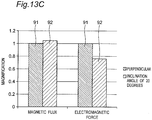
- the magnetic flux and the electromagnetic force in the case where the second air gap 212 is formed perpendicularly are represented by a bar graph 91
- the magnetic flux and the electromagnetic force in the case where the second air gap 212 is formed obliquely as in the third embodiment are represented by a bar graph 92
- respective magnifications 1.04 and 0.76 of the magnetic flux and the electromagnetic force in the case where the second air gap 212 is formed obliquely as in the third embodiment are shown when respective magnifications of the magnetic flux and the electromagnetic force in the case where the second air gap 212 is formed perpendicularly are defined as 1.
- the magnetic flux is increased by the increase in the effective magnetic path width, and the electromagnetic attractive force, in other words, electromagnetic force, is reduced by the decomposition into the radial force.
- the reduction in the electromagnetic attractive force in the axial direction makes it possible to reduce the axial force applied to the bearing. As a result, it is possible to reduce a drag torque and increase fuel efficiency of a vehicle.
- inclining the second air gap 212 to increase the cross-sectional area of the second air gap 212 makes it possible to lower the magnetic reluctance and reduce the field current. As a result, it is possible to increase the efficiency of the rotary electrical machine 10 and further increase the fuel efficiency of a vehicle.
- each inclined portion 212b is, for example, in a range from 10 degrees to 25 degrees from the axial direction of the rotational axis 7.
- each of the inclination directions of the inclined portions 212b in the first magnetic pole 21 and the second magnetic pole 22 may be an opposite direction.
- the inclined portion 212b on the second magnetic pole 22 side is gradually inclined from the inside to the outside in the radial direction as advancing from the transmission side to the engine side, while the inclined portion 212b on the first magnetic pole 21 side is gradually inclined outward from the inside in the radial direction as advancing from the engine side to the transmission side.
- the second air gap 212 may include only the inclined portion 212b without the perpendicular portions 212a and 212c.
- the field coil 2 is shifted in the axial direction of the rotational axis 7 to be in parallel to the rotor 1 with the second air gap 212 interposed between the field coil 2 and the rotor 1.
- the configuration of the third embodiment corresponding to Figs. 3 to 6 of the first embodiment is the same as the configuration of the first embodiment; thus description and illustration thereof is omitted.
- a field coil magnetic flux 15 is generated.
- the field coil magnetic flux 15 passes from the field core 6 through the second air gap 212, the first magnetic pole 21 of the rotor 1, the first air gap 11, the stator 3, the first air gap 11, the second magnetic pole 22 of the rotor 1, and the second air gap 212 and returns to the field core 6.
- the field coil magnetic flux 15 is generated, thereby magnetizing the first magnetic pole 21 and the second magnetic pole 22, for example, to N pole and S pole, respectively.
- an inverter (not shown) is driven to cause a three-phase alternating current flow through the stator 3 to magnetize the stator 3 and to cause a current flow through the field coil 2.
- Causing the current flow through the field coil 2 excites the first magnetic pole 21 and the second magnetic pole 22 of the rotor 1.
- the rotor 1 starts to rotate relative to the stator 3, and an electromotive force having an induced voltage is generated in the stator 3.
- the induced voltage increases according to a rotation speed of the rotor 1, and when the rotation speed reaches an initial explosion rotation speed lower than an idling speed corresponding to idling of the engine 8, the driving of the inverter is stopped, and the rotary electrical machine 10 automatically shifts to a power generation mode, in other words, a mode where the rotary electrical machine 10 serves as a dynamo to perform a power generating function, so as to hold a predetermined induced voltage (required voltage).
- an excitation current is adjusted to make the induced voltage constant at a predetermined induced voltage.
- the excitation current is first adjusted to make a magnetizing force of the field coil 2 constant. This is an intention of making the field coil 2 function just like a permanent magnet.
- the rotary electrical machine 10 functions as a dynamo.
- connecting the engine 8 and the rotary electrical machine 10 allows the engine to start and allows the rotary electrical machine 10 to function as a generator (dynamo) during traveling.
- the second air gap 212 between the field coil 2 and the rotor 1 is formed to be inclined relative to the rotational axis 7.
- the first magnetic pole 21 of the rotor 1 is an annular member having a large number of the claw portions 21b
- the second magnetic pole 22 is an annular member having a large number of the protrusions 22b
- the first and second magnetic poles 21, 22 are alternately arranged in the circumferential direction and held by the magnetic pole holding member 23 made of a nonmagnetic material.
- the third embodiment as shown in (a) of Fig. 14 , employed is a configuration in which the field coil 2 is shifted in the axial direction of the rotational axis 7 to be in parallel to the stator 3 and the rotor 1.
- This configuration causes only the two members of the stator 3 and the rotor 1 to be present outside the starting apparatus 4 in the radial direction, which eliminates the need for a space for disposing the field coil 2 outside the starting apparatus 4 in the radial direction.
- the radial dimension of the outside of the starting apparatus 4 by at least the space for disposing the field coil 2 or increase the thickness of the stator 3 or the rotor 1 by the space for disposing the field coil 2 for effective use of the space for disposing the field coil 2.
- the field coil 2 is disposed at a position shifted in the axial direction relative to the stator 3 and the rotor 1, it is possible to increase the thickness of the field coil 2 in the radial direction to increase the magnetic flux of the field coil 2 without considering the space for the stator 3 and the rotor 1. This makes it possible to increase the degree of freedom in designing.
- the field coil 2 is shifted in the axial direction relative to the stator 3 and the rotor 1 to form as the second air gap 212 an interval inclining from the axial direction between the field coil 2 and the rotor 1, which makes it possible to increase the efficiency of the rotary electrical machine 10 and reduce the axial force as described above.
- the rotor 1 of the rotary electrical machine 10 is connected to the starting apparatus 4 that is a synchronous rotating member synchronously rotating with an output shaft (rotational shaft) 7 of the engine 8, and the rotary electrical machine 10 is disposed so that the center axis of the output shaft of the engine 8 is aligned with a rotation axis of the rotor 1, which makes it possible to surely transmit a rotational driving force of the rotary electrical machine 10 to the engine 8 even in a cold state and surely start the engine 8 in the cold state.
- one of the stator 3 and the field coil 2 other than the rotor 1 is disposed in a narrow space on an inner circumferential side of the case 5 and an outer circumferential side of the starting apparatus 4.
- Such a disposition only requires two members to be arranged on diameters that are coaxial with the rotational axis 7 but different from each other, and thus allows an increase in the degree of freedom in designing and an increase in the output performance of the rotary electrical machine 10.
- the second air gap 212 has the inclined portion 212b that is an interval inclined from the axial direction of the rotational axis 7 on one end surface of the rotor 1 in the axial direction of the rotational axis 7, which makes it possible to increase the efficiency of rotary electrical machine 10 and reduce the axial force.
- a fourth embodiment of the present invention may have a structure in which a permanent magnet 27 is disposed inside the rotor 1 in the configuration of the third embodiment.
- the permanent magnet 27 having, for example, a rectangular plate shape is provided at the same circumferential position as each of the claw portions 21b of the first magnetic pole 21, on an inner diameter side of each of the claw portions 21b of the first magnetic pole 21 and on an outer diameter side of the second annular portion 22a of the second magnetic pole 22, and is sandwiched between an inner circumferential surface of each of the claw portions 21b and the outer circumferential surface of the second annular portion 22a.
- This arrangement causes, as shown in Fig. 16 , a magnet magnetic flux 28 of the permanent magnet 27 to be formed between each of the claw portions 21b of the first magnetic pole 21 and the protrusions 22b of the second magnetic pole 22.
- the permanent magnet 27 is a magnet primarily made of neodymium or a magnet primarily made of ferrite. Specifically, as the permanent magnet 27, various kinds of permanent magnets such as a SmCo magnet, an AlNiCo magnet, a neodymium bonded magnet, and the like can be used. The permanent magnet 27 is disposed entirely or partially an inner surface of each of the claw portions 21b.
- Such a configuration makes it possible to increase output performance by using the magnet magnetic flux 28 of the permanent magnet 27 in addition to a magnetic flux generated in the rotor 1 by the field coil 2. Further, holding the permanent magnet 27 with the claw portions 21b makes it possible to increase strength of the permanent magnet 27 against a centrifugal force, which can prevent the permanent magnet 27 from deforming due to the centrifugal force and thus increase centrifugal strength during high speed rotation.
- the rotary electrical machine according to the aspect of the present invention allows an increase in the degree of freedom in designing and an increase in the output performance, and is suitable for a power transmitting apparatus including a rotary electrical machine that integrally has a power generating function and an engine start function of an alternator and a starter motor of a vehicle.
Landscapes
- Engineering & Computer Science (AREA)
- Power Engineering (AREA)
- Synchronous Machinery (AREA)
- Iron Core Of Rotating Electric Machines (AREA)
- Permanent Field Magnets Of Synchronous Machinery (AREA)
- Connection Of Motors, Electrical Generators, Mechanical Devices, And The Like (AREA)
Abstract
Description
- The present invention relates to a brushless field winding type rotary electrical machine disposed on an outer circumference of a starting apparatus.
- As a conventional technique disclosed in Patent Document 1 (PTL 1), a rotary electrical machine shown in
Fig. 18 that supplies a magnetic flux from afield coil 102 that is stationary relative to arotor 101 has been proposed. Astator 103 is disposed outside therotor 101 in a radial direction. Such a structure makes it possible to eliminate the need for an electric power supply apparatus, the so-called slip ring using a brush conventionally required to magnetize therotor 101. This results in a brushless field winding type rotaryelectrical machine 110. Note that afirst air gap 111 is provided between thestator 103 and therotor 101, and asecond air gap 112 is provided between thefield coil 102 and therotor 101, both of which extend along an axial direction of arotational axis 107. - Further, as disclosed in Patent Document 2 (PTL 2), a structure in which a rotary electrical machine is disposed on an outer circumference of a starting apparatus has been proposed. Such a structure makes it possible to start an engine by connecting the engine and the rotary electrical machine and to eliminate the need for a starter and an alternator required for a conventional automobile by causing the rotary electrical machine to function as a generator during traveling.
-
- PTL 1:
JP 3445492 B2 - PTL 2:
JP 2010-516558 T - Combining these two Patent Documents, in other words, as shown in (b) of
Fig. 7 , when the brushless field winding type rotaryelectrical machine 110 is arranged on the outer circumference of thestarting apparatus 104, three members of thestator 103 fixed to acase 105, therotor 101, and thefield coil 102 are arranged in a narrow space on an inner circumferential side of thecase 105 and an outer circumferential side of the startingapparatus 104 coaxially with therotational axis 107 with different diameters, in a combination of the structures disclosed in the two Patent Documents. Hence, there are drawbacks that a severe restriction is imposed on a volume occupied by the rotaryelectrical machine 110, a degree of freedom in designing is limited, and the output performance of the rotaryelectrical machine 110 is limited. - Accordingly, an object of the present invention, having been conceived to solve the problem, is to provide a rotary electrical machine that allows an increase in degree of freedom in designing and an increase in output performance.
- In order to achieve the above-described object, the present invention is constructed as below.
- According to one aspect of the present invention, there is provided a brushless field winding type rotary electrical machine disposed between an engine and a transmission along a rotational axis and positioned between a case housing a starting apparatus and the starting apparatus, comprises:
- a stator held by the case, the stator including therein an AC coil that generates a rotating magnetic field with an alternating current;
- a field core held by the case, the field core including therein a field coil that is excited by a direct current;
- a rotor disposed on an outer circumference of the starting apparatus and held rotatably about the rotational axis relative to the stator and the field coil;
- a first air gap formed between the stator and the rotor, the first air gap being configured to allow a magnetic flux to flow between the stator and the rotor; and
- a second air gap formed between the field core and the rotor, the second air gap being configured to allow a magnetic flux to flow between the field core and the rotor and being an interval extending along a direction intersecting an axial direction of the rotational axis on one end surface of the rotor in the axial direction of the rotational axis.
- According to the aspect of the present invention, in a narrow space on an inner circumferential side of the case and an outer circumferential side of the starting apparatus, only the stator or the field coil other than the rotor is disposed, which only requires two members to be arranged on diameters that are coaxial with the rotational axis but different from each other, and thus allows an increase in the degree of freedom in designing and an increase in the output performance of the rotary electrical machine.
- These and other aspects and features of the present invention will become clear from the following description taken in conjunction with the embodiments thereof with reference to the accompanying drawings, in which:
-
Fig. 1 is an explanatory diagram showing a cross-sectional view taken approximately along a direction orthogonal to a rotational axis of a rotary electrical machine according to a first embodiment of the present invention and an arrangement relation of the rotary electrical machine relative to an engine and a transmission; -
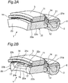
Fig. 2A is a perspective view of the rotary electrical machine according to the first embodiment, taken along the direction orthogonal to the rotational axis of the rotary electrical machine; -
Fig. 2B is a perspective view of the rotary electrical machine ofFig. 2A without a magnetic pole holding member; -
Fig. 3 is a front view of the rotary electrical machine according to the first embodiment, as viewed from a transmission side; -
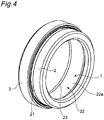
Fig. 4 is a perspective view of the rotary electrical machine according to the first embodiment; -
Fig. 5 is a perspective view of a rotor of the rotary electrical machine according to the first embodiment; -
Fig. 6 is an exploded perspective view of the rotor of the rotary electrical machine according to the first embodiment; -
Fig. 7 is an explanatory diagram showing a relation between a configuration of the first embodiment and a configuration of a combination example of conventional documents; -
Fig. 8 is an explanatory diagram showing a configuration according to a modification of the first embodiment; -
Fig. 9 is an explanatory diagram showing a cross-sectional view taken approximately along a direction orthogonal to a rotational axis of a rotary electrical machine according to a second embodiment of the present invention and an arrangement relation of the rotary electrical machine relative to an engine and a transmission; -
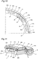
Fig. 10 is a partial front view of the rotary electrical machine according to the second embodiment; -
Fig. 11 is a perspective view of the rotary electrical machine according to the second embodiment without a magnetic pole holding member, taken along the direction orthogonal to the rotational axis of the rotary electrical machine; -
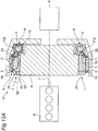
Fig. 12A is an explanatory diagram showing a cross-sectional view taken approximately along a direction orthogonal to a rotational axis of a rotary electrical machine according to a third embodiment of the present invention and an arrangement relation of the rotary electrical machine relative to an engine and a transmission; -
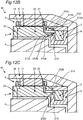
Fig. 12B is a partially enlarged view ofFig. 12A ; -
Fig. 12C is an explanatory diagram showing a cross-sectional view taken approximately along a direction orthogonal to a rotational axis of a rotary electrical machine according to a modification of the third embodiment of the present invention and an arrangement relation of the rotary electrical machine relative to an engine and a transmission; -
Fig. 13A is a perspective view of the rotary electrical machine according to the third embodiment, taken along the direction orthogonal to the rotational axis of the rotary electrical machine; -
Fig. 13B is a perspective view of the rotary electrical machine ofFig. 13A without a magnetic pole holding member; -
Fig. 13C is a graph showing, when respective magnifications of the magnetic flux and the electromagnetic force with the second air gap formed perpendicularly are defined as 1, respective magnifications of a magnetic flux and an axial electromagnetic force with a second air gap formed inclined (at, for example, an inclination angle of 20 degrees) as in the third embodiment; -
Fig. 14 is an explanatory diagram showing a relation between the configuration of the first embodiment and the configuration of the combination example of the conventional documents; -
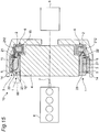
Fig. 15 is an explanatory diagram showing a cross-sectional view taken approximately along a direction orthogonal to a rotational axis of a rotary electrical machine according to a fourth embodiment of the present invention and an arrangement relation of the rotary electrical machine relative to an engine and a transmission; -
Fig. 16 is a partial front view of the rotary electrical machine according to the fourth embodiment; -
Fig. 17 is a perspective view of the rotary electrical machine according to the fourth embodiment without a magnetic pole holding member, taken along the direction orthogonal to the rotational axis of the rotary electrical machine; and -
Fig. 18 is an explanatory diagram showing a schematic configuration of a conventional rotary electrical machine. - Hereinafter, embodiments of the present invention will be described in detail with reference to the drawings.
- As shown in
Figs. 1 to 2B , a rotary electrical machine according to a first embodiment of the present invention is a brushless field winding type rotaryelectrical machine 10 that is disposed between anengine 8 and atransmission 9 along arotational axis 7 and is positioned between acase 5 housing astarting apparatus 4 and thestarting apparatus 4. The rotaryelectrical machine 10 includes at least astator 3, afield coil 2, and arotor 1. - The
stator 3 is fixedly held by thecase 5 in a non-rotatable manner and is configured by a cylindrical member having a plurality of slots on which anAC coil 14 is wound. Thestator 3 includes theAC coil 14 therein and generates a rotating magnetic field with an alternating current flowing through theAC coil 14. - The
field coil 2 is shifted along therotational axis 7 relative to thestator 3 and therotor 1, fixedly held by thecase 5 on a side adjacent to thetransmission 9 of thestator 3, and is excited by a direct current. Afield core 6 includes thefield coil 2 therein. Note that thefield coil 2 may be shifted along therotational axis 7 relative to thestator 3 and therotor 1 and on a side adjacent to the engine of thestator 3 via asecond air gap 12 rather than on a side adjacent to thetransmission 9 of the stator 3 (see aregion 89 enclosed by a long dashed short dashed line inFig. 1 ). - The
rotor 1 is fixedly disposed on an outer circumference of thestarting apparatus 4 such that an outer circumferential surface of therotor 1 faces an inner circumferential surface of thestator 3, and an end surface adjacent to the transmission of therotor 1 faces an end surface adjacent to the engine of thefield coil 2. Therotor 1 is held rotatably about therotational axis 7 relative to thestator 3 and thefield coil 2. - The
first air gap 11 is formed between thestator 3 and therotor 1 and allows a magnetic flux to flow between thestator 3 and therotor 1. Thefirst air gap 11 is an interval extending along an axial direction of therotational axis 7 between the inner circumferential surface of thestator 3 and the outer circumferential surface of therotor 1. - The
second air gap 12 is formed between thefield core 6 and therotor 1 and allows a magnetic flux to flow between thefield coil 2 and therotor 1. Thesecond air gap 12 is an interval extending along a direction intersecting the axial direction of therotational axis 7, for example, along a radial direction orthogonal to the axial direction between thefield core 6 and therotor 1 on the end surface adjacent to the transmission of therotor 1 and on an end surface adjacent to the engine of thefield core 6 in the axial direction of therotational axis 7. - Accordingly, the
field coil 2 is shifted in the axial direction of therotational axis 7 to be in parallel to therotor 1 with thesecond air gap 12 interposed between thefield coil 2 and therotor 1. - On the other hand, as shown in
Figs. 3 to 6 , therotor 1 is composed of a combination of a firstmagnetic pole 21, a secondmagnetic pole 22, and a magneticpole holding member 23. Note that a longitudinal cross-sectional view taken along line A-A ofFig. 3 corresponds to a cross-sectional view of the rotaryelectrical machine 10, thestarting apparatus 4, and the like shown in the center ofFig. 1 . - The first
magnetic pole 21 is composed of a soft magnetic material such as iron and has a plurality ofclaw portions 21b each of which has, for example, a rectangular thin plate shape and protrude from a firstannular portion 21a in the axial direction of therotational axis 7. Theclaw portions 21b are arranged at regular intervals, for example, equal intervals, in a circumferential direction thereof and all have the same length in the axial direction of therotational axis 7. An outer circumferential surface of each of theclaw portions 21b is flush with an outer circumferential surface of the firstannular portion 21a. When the firstmagnetic pole 21 and the secondmagnetic pole 22 are combined, theclaw portions 21b are kept from coming into contact with the secondmagnetic pole 22, and aradial interval 16 is formed extending in the radial direction. - The second
magnetic pole 22 is composed of a soft magnetic material such as iron and is disposed inside the firstannular portion 21a with theradial interval 16 interposed therebetween. The secondmagnetic pole 22 has a plurality ofprotrusions 22b each of which has, for example, a rectangular plate shape, protrude in the radial direction, and are arranged on an outer circumferential surface of a secondannular portion 22a atcircumferential intervals 17 in the circumferential direction. The secondannular portion 22a is disposed partially overlapping the firstannular portion 21a. Theprotrusions 22b are also arranged at regular intervals, for example, equal intervals, in the circumferential direction and all have the same height in the radial direction. Theprotrusions 22b all have the same length in the axial direction of therotational axis 7 and are shorter in length than theclaw portions 21b. An outer circumferential surface of each of theprotrusions 22b is disposed on a circle coaxial with a rotation axis of therotor 1. Each of theprotrusions 22b extends to an end edge adjacent to the engine of the secondannular portion 22a to form a second leadingend locking portion 22c while extending toward but terminating short of an end edge adjacent to the transmission of the secondannular portion 22a to form an insertingportion 22d having a thin annular shape without theprotrusion 22b. The firstmagnetic pole 21 is moved in the axial direction relative to the secondmagnetic pole 22 to insert each of theclaw portions 21b of the firstmagnetic pole 21 into a middle part of thecircumferential interval 17 between theprotrusions 22b adjacent to each other, thereby combining the firstmagnetic pole 21 and the secondmagnetic pole 22 with theclaw portion 21b and theprotrusion 22b alternately arranged in the circumferential direction. The firstannular portion 21a of the firstmagnetic pole 21 is configured to be disposed outward the insertingportion 22d with theradial interval 16 interposed therebetween. As shown inFig. 5 , with the firstmagnetic pole 21 and the secondmagnetic pole 22 combined with each other, anaxial interval 19 is present between each of theprotrusions 22b and the firstannular portion 21a, and, between each of theclaw portions 21b and the secondmagnetic pole 22, thecircumferential interval 17 in the circumferential direction and theradial interval 16 in the radial direction are present. Accordingly, the firstmagnetic pole 21 and the secondmagnetic pole 22 are kept from coming into contact with each other. In order to fix the firstmagnetic pole 21 and the secondmagnetic pole 22 to each other in this state, the magneticpole holding member 23 is further provided. - The magnetic
pole holding member 23 is composed of a nonmagnetic material such as aluminum or austenitic stainless steel and is an annular member. The magneticpole holding member 23 has afitting portion 23a, for example, on an outer circumferential side. To thefitting portion 23a, a first leadingend locking portion 21c of each of theclaw portions 21b of the firstmagnetic pole 21 and the second leadingend locking portion 22c of each of theprotrusions 22b of the secondmagnetic pole 22 are fixedly fitted. The first leadingend locking portion 21c and the second leadingend locking portion 22c are fitted to thefitting portion 23a and fixed by bolting, shrink fitting, brazing, or the like, so that the firstmagnetic pole 21 and the secondmagnetic pole 22 are fixedly held by the magneticpole holding member 23 with the firstmagnetic pole 21 and the secondmagnetic pole 22 kept from coming into contact with each other. - As a specific example, the first leading
end locking portion 21c of each of theclaw portions 21b of the firstmagnetic pole 21 and the second leadingend locking portion 22c of each of theprotrusions 22b of the secondmagnetic pole 22 are each formed in a step portion, and the step portion is fitted to an engaging recess of thefitting portion 23a and fixedly held in the radial direction. The second leadingend locking portion 22c is disposed at a leading end of each of theprotrusions 22b as an example, but may be disposed at a leading end of the secondannular portion 22a. When the magnetic flux is made to flow from thefield coil 2 to magnetize the firstmagnetic pole 21 and the secondmagnetic pole 22, this configuration achieves efficient magnetization by causing the magneticpole holding member 23 that is nonmagnetic to prevent a magnetic short, and allows the firstmagnetic pole 21 and the secondmagnetic pole 22 to be mechanically held by the magneticpole holding member 23. Further, the configuration in which the first leadingend locking portion 21c of each of theclaw portions 21b of the firstmagnetic pole 21 is fixedly fitted to and held by thefitting portion 23a of the magneticpole holding member 23 suppresses outward deformation of theclaw portions 21b due to a rotational centrifugal force, and thus makes it possible to increase rotational strength. - In the rotary
electrical machine 10 configured as described above, when thefield coil 2 is energized, a field coilmagnetic flux 15 is generated. The field coilmagnetic flux 15 passes from thefield core 6 through thesecond air gap 12, the firstmagnetic pole 21 of therotor 1, thefirst air gap 11, thestator 3, thefirst air gap 11, the secondmagnetic pole 22 of therotor 1, and thesecond air gap 12 and returns to thefield core 6. At this time, for example, when a direct current is made to flow through thefield coil 2, the field coilmagnetic flux 15 is generated, thereby magnetizing the firstmagnetic pole 21 and the secondmagnetic pole 22 to N pole and S pole, respectively. - A description will be given of a configuration where such a rotary
electrical machine 10 serves as a starter to perform a start function. In accordance with a command to start theengine 8, an inverter (not shown) is driven to cause a three-phase alternating current flow through thestator 3 to magnetize thestator 3 and to cause a current flow through thefield coil 2. Causing the current flow through thefield coil 2 excites the firstmagnetic pole 21 and the secondmagnetic pole 22 of therotor 1. As a result, therotor 1 starts to rotate relative to thestator 3, and an electromotive force having an induced voltage is generated in thestator 3. - Thereafter, the induced voltage increases according to a rotation speed of the
rotor 1, and when the rotation speed reaches an initial explosion rotation speed lower than an idling speed corresponding to idling of theengine 8, the driving of the inverter is stopped, and thereafter, the rotaryelectrical machine 10 automatically shifts to a power generation mode, in other words, a mode where the rotaryelectrical machine 10 serves as a dynamo to perform a power generating function, so as to hold a predetermined induced voltage (required voltage). - In the power generation mode, when the
field coil 2 continues to excite, an excitation current is adjusted to make the induced voltage constant at a predetermined induced voltage. When the excitation current is adjusted, the excitation current is first adjusted to make a magnetizing force of thefield coil 2 constant. This is an intention of making thefield coil 2 function just like a permanent magnet. As described above, when therotor 1 rotates in a state as if a permanent magnet is disposed, the rotaryelectrical machine 10 functions as a dynamo. - As a result, connecting the
engine 8 and the rotaryelectrical machine 10 allows the engine to start and allows the rotaryelectrical machine 10 to function as a generator (dynamo) during traveling. - According to the first embodiment, in the brushless field winding type rotary
electrical machine 10 disposed on the outer circumference of theautomobile starting apparatus 4, thesecond air gap 12 between thefield coil 2 and therotor 1 is formed on a plane perpendicular to therotational axis 7. Specifically, employed is a structure in which the firstmagnetic pole 21 of therotor 1 is an annular member having a large number of theclaw portions 21b, the secondmagnetic pole 22 is an annular member having a large number of theprotrusions 22b, and the first and secondmagnetic poles pole holding member 23 made of a nonmagnetic material. Such a configuration can exhibit the following effects. - First, as shown in (b) of
Fig. 7 as a combination example ofconventional PTL electrical machine 110 is disposed outside thestarting apparatus 104 in the radial direction, and three members of thestator 103, therotor 101, and thefield coil 102 are arranged in a space between thecase 105 and thestarting apparatus 104 from the outside to the inside in the radial direction, the more the number of turns of thefield coil 102 increases to increase the magnetic flux of thefield coil 102, the more the thickness in the radial direction increases, which makes it unable to put the three members into the space and accordingly fails to increase the magnetic flux. - On the other hand, in the first embodiment, as shown in (a) of
Fig. 7 , employed is a configuration in which thefield coil 2 is shifted in the axial direction of therotational axis 7 to be in parallel to thestator 3 and therotor 1. This configuration causes only the two members of thestator 3 and therotor 1 to be present outside thestarting apparatus 4 in the radial direction, which eliminates the need for a space for disposing thefield coil 2 outside thestarting apparatus 4 in the radial direction. Accordingly, it is possible to reduce the radial dimension of the outside of thestarting apparatus 4 by at least the space for disposing thefield coil 2 or increase the thickness of thestator 3 or therotor 1 by the space for disposing thefield coil 2, for example, for effective use of the space for disposing thefield coil 2. Further, since thefield coil 2 is disposed at a position shifted in the axial direction relative to thestator 3 and therotor 1, it is possible to increase the thickness of thefield coil 2 in the radial direction to increase the magnetic flux of thefield coil 2 without considering the space for thestator 3 and therotor 1. This makes it possible to increase the degree of freedom in designing. - Further, as shown in (b) of
Fig. 7 , when thestator 103, therotor 101, and thefield coil 102 are arranged in that order from the outside to the inside in the radial direction, it is required that a dimension of an interval between therotor 101 and thefield coil 102 to be designed in consideration of the change in thickness caused by expansion or the like due to the centrifugal force applied to therotor 101 and to be generally designed larger than a required dimension. - On the other hand, as shown in (a) of
Fig. 7 , thefield coil 2 is shifted relative to thestator 3 and therotor 1 in the axial direction to form an interval radially extending between thefield coil 2 and therotor 1 as thesecond air gap 12, which eliminates the need to take into consideration the change in thickness caused by expansion or the like due to the centrifugal force applied to therotor 1, and only requires adjustment of the interval dimension of thesecond air gap 12 along the axial direction. Therefore, the influence of the centrifugal force can be reduced. - Further, in the radial arrangement as shown in (b) of
Fig. 7 , concentricity (position adjustment of concentric positions) between therotor 101 that is a rotating side and thefield coil 102 that is a stationary side is strictly adjusted; however, as shown in (a) ofFig. 7 , when thefield coil 102 is shifted in the axial direction, there is no need to adjust the concentricity between therotor 1 that is the rotating side and thefield coil 2 that is the stationary side as strict as the configuration in (b) ofFig. 7 . - Further, in the configuration in (a) of
Fig. 7 , allowing thefield coil 2 of therotor 1 to be disposed in either a space adjacent to the engine or a space adjacent to the transmission in the axial direction makes it possible to use the space effectively. - Further, the
rotor 1 of the rotaryelectrical machine 10 is connected to thestarting apparatus 4 that is a synchronous rotating member synchronously rotating with an output shaft (rotational shaft) 7 of theengine 8, and the rotaryelectrical machine 10 is disposed so that the center axis of the output shaft of theengine 8 is aligned with a rotation axis of therotor 1, which makes it possible to surely transmit a rotational driving force of the rotaryelectrical machine 10 to theengine 8 even in a cold state and surely start theengine 8 in the cold state. - Note that the present invention is not limited to the first embodiment and may be implemented in various other modes. For example, as a modification shown in
Fig. 8 , in the first embodiment, an interchange in position between thestator 3 and thefield coil 2 may be made to cause thefield coil 2 to be disposed on an outer side in the radial direction of therotor 1 and cause thestator 3 to be shifted in the axial direction of therotational axis 7 relative to therotor 1. In other words, thefirst air gap 11 between therotor 1 and thestator 3 is formed as an interval extending along a direction intersecting the axial direction of therotational axis 7, for example, along the radial direction orthogonal to the axial direction. On the other hand, thesecond air gap 12 between thefield coil 2 and therotor 1 is formed as an interval extending along the axial direction of therotational axis 7. - This configuration not only exhibits the action effect of the first embodiment, but also causes the
first air gap 11 between therotor 1 and thestator 3 to be formed as an interval extending along the radial direction orthogonal to the axial direction of therotational axis 7, which eliminates the need to take into consideration the change in thickness caused by expansion or the like due to the centrifugal force applied to therotor 1 in designing thestator 3. - As shown in
Figs. 9 to 11 , a second embodiment of the present invention may have a structure in which apermanent magnet 27 is disposed inside therotor 1 in the configuration of the first embodiment. - More specifically, the
permanent magnet 27 having, for example, a rectangular plate shape is provided at the same circumferential position as each of theclaw portions 21b of the firstmagnetic pole 21 is disposed, on an inner diameter side of each of theclaw portions 21b of the firstmagnetic pole 21 and on an outer diameter side of the secondannular portion 22a of the secondmagnetic pole 22, and is sandwiched between an inner circumferential surface of each of theclaw portions 21b and the outer circumferential surface of the secondannular portion 22a. This arrangement causes, as shown inFig. 10 , a magnetmagnetic flux 28 of thepermanent magnet 27 to be formed between each of theclaw portions 21b of the firstmagnetic pole 21 and theprotrusions 22b of the secondmagnetic pole 22. - The
permanent magnet 27 is a magnet primarily made of neodymium or a magnet primarily made of ferrite. Specifically, as thepermanent magnet 27, various kinds of permanent magnets such as a SmCo magnet, an AlNiCo magnet, a neodymium bonded magnet, and the like can be used. Thepermanent magnet 27 is disposed entirely or partially an inner surface of each of theclaw portions 21b. - Such a configuration makes it possible to increase output performance by using the magnet
magnetic flux 28 of thepermanent magnet 27 in addition to a magnetic flux generated in therotor 1 by thefield coil 2. Further, holding thepermanent magnet 27 with theclaw portions 21b makes it possible to increase strength of thepermanent magnet 27 against a centrifugal force, which can prevent thepermanent magnet 27 from being deformed due to the centrifugal force and thus increase centrifugal strength during high speed rotation. - The
second air gap 12 is not limited to an interval extending along the radial direction orthogonal to the axial direction of therotational axis 7 as described in the first and second embodiments, and may be an interval inclined from the axis direction of therotational axis 7. An example having such an interval will be described below. - As shown in
Figs. 12A to 13B , a rotary electrical machine according to a third embodiment of the present invention is a brushless field winding type rotaryelectrical machine 10 that is disposed between anengine 8 and atransmission 9 along arotational axis 7 and is positioned between acase 5 housing astarting apparatus 4 and thestarting apparatus 4. The rotaryelectrical machine 10 includes at least astator 3, afield coil 2, and arotor 1. - The
stator 3 is fixedly held by thecase 5 in a non-rotatable manner and is configured by a cylindrical member having a plurality of slots on which anAC coil 14 is wound. Thestator 3 includes theAC coil 14 therein and generates a rotating magnetic field with an alternating current flowing through theAC coil 14. - The
field coil 2 is shifted along therotational axis 7 relative to thestator 3 and therotor 1, fixedly held by thecase 5 on a side adjacent to thetransmission 9 of thestator 3, and is excited by a direct current. Afield core 6 includes thefield coil 2 therein. Note that thefield coil 2 may be disposed closer to the engine than thestator 3 and therotor 1 along therotational axis 7, that is, on a side adjacent to the engine of thestator 3 via asecond air gap 212 rather than on a side adjacent to thetransmission 9 of the stator 3 (see aregion 89 enclosed by a long dashed short dashed line inFig. 12A ). - The
rotor 1 is fixedly disposed on an outer circumference of thestarting apparatus 4 such that an outer circumferential surface of therotor 1 faces an inner circumferential surface of thestator 3, and an end surface adjacent to the transmission of therotor 1 faces an end surface adjacent to the engine of thefield coil 2. Therotor 1 is held rotatably about therotational axis 7 relative to thestator 3 and thefield coil 2. - The
first air gap 11 is formed between thestator 3 and therotor 1 and allows a magnetic flux to flow between thestator 3 and therotor 1. Thefirst air gap 11 is an interval extending along an axial direction of therotational axis 7 between the inner circumferential surface of thestator 3 and the outer circumferential surface of therotor 1. - The
second air gap 212 is formed between thefield core 6 and therotor 1 and allows a magnetic flux to flow between thefield coil 2 and therotor 1. Thesecond air gap 212 is an interval inclined from the axial direction of therotational axis 7 at an inclination angle α between thefield core 6 and therotor 1 on the end surface adjacent to the transmission of therotor 1 and on an end surface adjacent to the engine of thefield core 6 in the axial direction of therotational axis 7. - More specifically, as shown in
Fig. 13A , thesecond air gap 212 is formed between thefield core 6 and the secondmagnetic pole 22 of therotor 1 on the end surface adjacent to the transmission of therotor 1 and on the end surface adjacent to the engine of thefield core 6 in the axial direction of therotational axis 7, and between thefield core 6 and the firstmagnetic pole 21 of therotor 1 on the end surface adjacent to the transmission of therotor 1 and on the end surface adjacent to the engine of thefield core 6 in the axial direction of therotational axis 7. - First, between the
field core 6 and the secondmagnetic pole 22 of therotor 1, on the end surface adjacent to the transmission of therotor 1 and on the end surface adjacent to the engine of thefield core 6 in the axial direction of therotational axis 7, thesecond air gap 212 includes a firstperpendicular portion 212a that is an interval perpendicular to the axial direction of therotational axis 7, aninclined portion 212b that is an interval inclined from the axial direction of therotational axis 7 at the inclination angle α, and a secondperpendicular portion 212c that is an interval perpendicular to the axial direction of therotational axis 7 in that order from a center of therotational axis 7. The firstperpendicular portion 212a, theinclined portion 212b, and the secondperpendicular portion 212c are continuously connected to each other. An inclination direction of theinclined portion 212b is gradually inclined from the inside to the outside in the radial direction as advancing from the engine side to the transmission side. The intervals of the firstperpendicular portion 212a, theinclined portion 212b, and the secondperpendicular portion 212c are approximately the same. - Further, between the
field core 6 and the firstmagnetic pole 21 of therotor 1, on the end surface adjacent to the transmission of therotor 1 and on the end surface adjacent to the engine of thefield core 6 in the axial direction of therotational axis 7, thesecond air gap 212 includes a firstperpendicular portion 212a that is an interval perpendicular to the axial direction of therotational axis 7, aninclined portion 212b that is an interval inclined from the axial direction of therotational axis 7 at the inclination angle α, and a secondperpendicular portion 212c that is an interval perpendicular to the axial direction of therotational axis 7 in that order from the center of therotational axis 7. The firstperpendicular portion 212a, theinclined portion 212b, and the secondperpendicular portion 212c are continuously connected to each other. In contrast to thesecond air gap 212 on the secondmagnetic pole 22 side, an inclination direction of theinclined portion 212b is gradually inclined from the inside to the outside in the radial direction as advancing from the transmission side to the engine side. The intervals of the firstperpendicular portion 212a, theinclined portion 212b, and the secondperpendicular portion 212c are approximately the same. - Consequently, when the inclination direction of the
second air gap 212 on the firstmagnetic pole 21 side and the inclination direction of thesecond air gap 212 on the secondmagnetic pole 22 side are aligned with each other, as shown inFig. 12B , thesecond air gaps 212 are arranged in an approximate V shape whose apex is directed from the engine side to the transmission side. This approximate V shape is an example and may be an approximate inverted V shape or a parallel shape. In other words, each of the inclination direction of thesecond air gap 212 on the firstmagnetic pole 21 side and the inclination direction of thesecond air gap 212 on the secondmagnetic pole 22 side may have any direction and any inclination angle. As an example, it is preferable that the inclination directions of the two be identical to each other from the viewpoint of balancing the magnetic flux and the axial force. - The
second air gap 212 only needs to include at least theinclined portion 212b, and may further include one or both of theperpendicular portions - Here, the reason why the
second air gap 212 is inclined in this way will be described. - When the
second air gap 212 between therotor 1 and thefield coil 2 is formed as a plane perpendicular to the axial direction of therotational axis 7, magnetic reluctance becomes high due to a small air gap cross-sectional area, which may cause an increase in field current that is required for a rotor field. Further, when thesecond air gap 212 is formed perpendicular to the axial direction of therotational axis 7, an electromagnetic attractive force is generated in the axial direction, and a large axial force may be applied to a bearing (not shown) that supports thestarting apparatus 4. - In particular, in a case where the
second air gap 212 is formed perpendicular to the axial direction of therotational axis 7, an effective magnetic path width of thesecond air gap 212 in the cross section is equivalent to a thickness of thefield core 6 and a thickness of the magnetic pole. Further, when thefield core 6 is excited, the electromagnetic attractive force acts between thefield core 6 and therotor 1. Therefore, when thesecond air gap 212 is formed perpendicular to the axial direction of therotational axis 7, all of the electromagnetic attractive force act as the axial force. - On the other hand, as in the third embodiment, when the
second air gap 212 is inclined from the axial direction of therotational axis 7, compared with the case where thesecond air gap 212 is formed perpendicular to the axial direction, the effective magnetic path width of thesecond air gap 212 can be increased, and the axial force can be reduced by decomposing the electromagnetic attractive force into not only the axial force but also a radial force. - Here, in
Fig. 13C , the magnetic flux and the electromagnetic force in the case where thesecond air gap 212 is formed perpendicularly are represented by abar graph 91, the magnetic flux and the electromagnetic force in the case where thesecond air gap 212 is formed obliquely as in the third embodiment are represented by abar graph 92. Here, respective magnifications 1.04 and 0.76 of the magnetic flux and the electromagnetic force in the case where thesecond air gap 212 is formed obliquely as in the third embodiment are shown when respective magnifications of the magnetic flux and the electromagnetic force in the case where thesecond air gap 212 is formed perpendicularly are defined as 1. In the case where thesecond air gap 212 is formed obliquely as in the third embodiment, as compared with the case where thesecond air gap 212 is formed perpendicularly, the magnetic flux is increased by the increase in the effective magnetic path width, and the electromagnetic attractive force, in other words, electromagnetic force, is reduced by the decomposition into the radial force. - Accordingly, the reduction in the electromagnetic attractive force in the axial direction makes it possible to reduce the axial force applied to the bearing. As a result, it is possible to reduce a drag torque and increase fuel efficiency of a vehicle.
- Further, inclining the
second air gap 212 to increase the cross-sectional area of thesecond air gap 212 makes it possible to lower the magnetic reluctance and reduce the field current. As a result, it is possible to increase the efficiency of the rotaryelectrical machine 10 and further increase the fuel efficiency of a vehicle. - In order to reliably achieve the various effects described above, the inclination angle α of each
inclined portion 212b is, for example, in a range from 10 degrees to 25 degrees from the axial direction of therotational axis 7. - Note that each of the inclination directions of the
inclined portions 212b in the firstmagnetic pole 21 and the secondmagnetic pole 22 may be an opposite direction. In other words, theinclined portion 212b on the secondmagnetic pole 22 side is gradually inclined from the inside to the outside in the radial direction as advancing from the transmission side to the engine side, while theinclined portion 212b on the firstmagnetic pole 21 side is gradually inclined outward from the inside in the radial direction as advancing from the engine side to the transmission side. - Further, as shown in
Fig. 12C , thesecond air gap 212 may include only theinclined portion 212b without theperpendicular portions - Accordingly, the
field coil 2 is shifted in the axial direction of therotational axis 7 to be in parallel to therotor 1 with thesecond air gap 212 interposed between thefield coil 2 and therotor 1. - Note that, the configuration of the third embodiment corresponding to
Figs. 3 to 6 of the first embodiment is the same as the configuration of the first embodiment; thus description and illustration thereof is omitted. - In the rotary
electrical machine 10 configured as described above, when thefield coil 2 is energized, a field coilmagnetic flux 15 is generated. The field coilmagnetic flux 15 passes from thefield core 6 through thesecond air gap 212, the firstmagnetic pole 21 of therotor 1, thefirst air gap 11, thestator 3, thefirst air gap 11, the secondmagnetic pole 22 of therotor 1, and thesecond air gap 212 and returns to thefield core 6. At this time, for example, when a direct current is made to flow through thefield coil 2, the field coilmagnetic flux 15 is generated, thereby magnetizing the firstmagnetic pole 21 and the secondmagnetic pole 22, for example, to N pole and S pole, respectively. - A description will be given of a configuration where such a rotary
electrical machine 10 serves as a starter to perform a start function. In accordance with a command to start theengine 8, an inverter (not shown) is driven to cause a three-phase alternating current flow through thestator 3 to magnetize thestator 3 and to cause a current flow through thefield coil 2. Causing the current flow through thefield coil 2 excites the firstmagnetic pole 21 and the secondmagnetic pole 22 of therotor 1. As a result, therotor 1 starts to rotate relative to thestator 3, and an electromotive force having an induced voltage is generated in thestator 3. - Thereafter, the induced voltage increases according to a rotation speed of the
rotor 1, and when the rotation speed reaches an initial explosion rotation speed lower than an idling speed corresponding to idling of theengine 8, the driving of the inverter is stopped, and the rotaryelectrical machine 10 automatically shifts to a power generation mode, in other words, a mode where the rotaryelectrical machine 10 serves as a dynamo to perform a power generating function, so as to hold a predetermined induced voltage (required voltage). - In the power generation mode, when the
field coil 2 continues to excite, an excitation current is adjusted to make the induced voltage constant at a predetermined induced voltage. When the excitation current is adjusted, the excitation current is first adjusted to make a magnetizing force of thefield coil 2 constant. This is an intention of making thefield coil 2 function just like a permanent magnet. As described above, when therotor 1 rotates in a state as if a permanent magnet is disposed, the rotaryelectrical machine 10 functions as a dynamo. - As a result, connecting the
engine 8 and the rotaryelectrical machine 10 allows the engine to start and allows the rotaryelectrical machine 10 to function as a generator (dynamo) during traveling. - According to the third embodiment, in the brushless field winding type rotary
electrical machine 10 disposed on the outer circumference of theautomobile starting apparatus 4, thesecond air gap 212 between thefield coil 2 and therotor 1 is formed to be inclined relative to therotational axis 7. Specifically, employed is a structure in which the firstmagnetic pole 21 of therotor 1 is an annular member having a large number of theclaw portions 21b, the secondmagnetic pole 22 is an annular member having a large number of theprotrusions 22b, and the first and secondmagnetic poles pole holding member 23 made of a nonmagnetic material. Such a configuration can exhibit the following effects. - First, as shown in (b) of
Fig. 14 as a combination example ofconventional PTL electrical machine 110 is disposed outside thestarting apparatus 104 in the radial direction, and three members of thestator 103, therotor 101, and thefield coil 102 are arranged in a space between thecase 105 and thestarting apparatus 104 from the outside to the inside in the radial direction, the more the number of turns of thefield coil 102 increases to increase the magnetic flux of thefield coil 102, the more the thickness in the radial direction increases, which makes it unable to put the three members into the space and accordingly fails to increase the magnetic flux. - On the other hand, in the third embodiment, as shown in (a) of
Fig. 14 , employed is a configuration in which thefield coil 2 is shifted in the axial direction of therotational axis 7 to be in parallel to thestator 3 and therotor 1. This configuration causes only the two members of thestator 3 and therotor 1 to be present outside thestarting apparatus 4 in the radial direction, which eliminates the need for a space for disposing thefield coil 2 outside thestarting apparatus 4 in the radial direction. Accordingly, it is possible to reduce the radial dimension of the outside of thestarting apparatus 4 by at least the space for disposing thefield coil 2 or increase the thickness of thestator 3 or therotor 1 by the space for disposing thefield coil 2 for effective use of the space for disposing thefield coil 2. Further, since thefield coil 2 is disposed at a position shifted in the axial direction relative to thestator 3 and therotor 1, it is possible to increase the thickness of thefield coil 2 in the radial direction to increase the magnetic flux of thefield coil 2 without considering the space for thestator 3 and therotor 1. This makes it possible to increase the degree of freedom in designing. - Further, as shown in (b) of
Fig. 14 , when thestator 103, therotor 101, and thefield coil 102 are arranged from the outside to the inside in the radial direction, it is required that a dimension of an interval between therotor 101 and thefield coil 102 to be designed in consideration of the change in thickness caused by expansion due to the centrifugal force applied to therotor 101 and be generally designed larger than a required dimension. - On the other hand, as shown in (a) of
Fig. 14 , thefield coil 2 is shifted in the axial direction relative to thestator 3 and therotor 1 to form as thesecond air gap 212 an interval inclining from the axial direction between thefield coil 2 and therotor 1, which makes it possible to increase the efficiency of the rotaryelectrical machine 10 and reduce the axial force as described above. - Further, in the radial arrangement as shown in (b) of
Fig. 14 , concentricity (position adjustment of concentric positions) between therotor 101 on a rotating side and thefield coil 102 on a stationary side is strictly adjusted; however, as shown in (a) ofFig. 14 , when thefield coil 102 is shifted in the axial direction, there is no need to adjust the concentricity between therotor 1 on the rotating side and thefield coil 2 on the stationary side as strict as the configuration in (b) ofFig. 14 . - Further, in the configuration in (a) of
Fig. 14 , allowing thefield coil 2 to be disposed in either a space in the engine or a space adjacent to the transmission of therotor 1 in the axial direction makes it possible to use the space effectively. - Further, the
rotor 1 of the rotaryelectrical machine 10 is connected to thestarting apparatus 4 that is a synchronous rotating member synchronously rotating with an output shaft (rotational shaft) 7 of theengine 8, and the rotaryelectrical machine 10 is disposed so that the center axis of the output shaft of theengine 8 is aligned with a rotation axis of therotor 1, which makes it possible to surely transmit a rotational driving force of the rotaryelectrical machine 10 to theengine 8 even in a cold state and surely start theengine 8 in the cold state. - Therefore, according to the third embodiment, in a narrow space on an inner circumferential side of the
case 5 and an outer circumferential side of thestarting apparatus 4, one of thestator 3 and thefield coil 2 other than therotor 1 is disposed. Such a disposition only requires two members to be arranged on diameters that are coaxial with therotational axis 7 but different from each other, and thus allows an increase in the degree of freedom in designing and an increase in the output performance of the rotaryelectrical machine 10. Furthermore, thesecond air gap 212 has the inclinedportion 212b that is an interval inclined from the axial direction of therotational axis 7 on one end surface of therotor 1 in the axial direction of therotational axis 7, which makes it possible to increase the efficiency of rotaryelectrical machine 10 and reduce the axial force. - As shown in
Figs. 15 to 17 , a fourth embodiment of the present invention may have a structure in which apermanent magnet 27 is disposed inside therotor 1 in the configuration of the third embodiment. - More specifically, the
permanent magnet 27 having, for example, a rectangular plate shape is provided at the same circumferential position as each of theclaw portions 21b of the firstmagnetic pole 21, on an inner diameter side of each of theclaw portions 21b of the firstmagnetic pole 21 and on an outer diameter side of the secondannular portion 22a of the secondmagnetic pole 22, and is sandwiched between an inner circumferential surface of each of theclaw portions 21b and the outer circumferential surface of the secondannular portion 22a. This arrangement causes, as shown inFig. 16 , a magnetmagnetic flux 28 of thepermanent magnet 27 to be formed between each of theclaw portions 21b of the firstmagnetic pole 21 and theprotrusions 22b of the secondmagnetic pole 22. - The
permanent magnet 27 is a magnet primarily made of neodymium or a magnet primarily made of ferrite. Specifically, as thepermanent magnet 27, various kinds of permanent magnets such as a SmCo magnet, an AlNiCo magnet, a neodymium bonded magnet, and the like can be used. Thepermanent magnet 27 is disposed entirely or partially an inner surface of each of theclaw portions 21b. - Such a configuration makes it possible to increase output performance by using the magnet
magnetic flux 28 of thepermanent magnet 27 in addition to a magnetic flux generated in therotor 1 by thefield coil 2. Further, holding thepermanent magnet 27 with theclaw portions 21b makes it possible to increase strength of thepermanent magnet 27 against a centrifugal force, which can prevent thepermanent magnet 27 from deforming due to the centrifugal force and thus increase centrifugal strength during high speed rotation. - By appropriately combining arbitrary embodiments or modifications of the above various embodiments or modifications, respective effects can be produced. Additionally, combination between embodiments, combination between working examples, or combination between an embodiment(s) and a working example(s) is possible, and combination between characteristics in different embodiments or working examples is possible as well.
- Although the present invention has been fully described in connection with the embodiments thereof with reference to the accompanying drawings, it is to be noted that various changes and modifications are apparent to those skilled in the art. Such changes and modifications are to be understood as included within the scope of the present invention as defined by the appended claims unless they depart therefrom.
- The rotary electrical machine according to the aspect of the present invention allows an increase in the degree of freedom in designing and an increase in the output performance, and is suitable for a power transmitting apparatus including a rotary electrical machine that integrally has a power generating function and an engine start function of an alternator and a starter motor of a vehicle.
-
- 1. rotor
- 2. field coil
- 3. stator
- 4. starting apparatus
- 5. case
- 6. field core
- 7. rotational axis
- 8. engine
- 9. transmission
- 10. brushless field winding type rotary electrical machine
- 11. first air gap
- 12. second air gap
- 14. AC coil
- 15. field coil magnetic flux
- 16. radial interval
- 17. circumferential interval
- 19. axial interval
- 21. first magnetic pole
- 21a. first annular portion
- 21b. claw portion
- 21c. first leading end locking portion
- 22. second magnetic pole
- 22a. second annular portion
- 22b. protrusion
- 22c. second leading end locking portion
- 22d. inserting portion
- 23. magnetic pole holding member
- 23a. fitting portion
- 27. permanent magnet
- 28. magnetic flux of permanent magnet
- 89. region where field coil is disposed on a side adjacent to engine of stator
- 91, 92. bar graph
- 212. second air gap
- 212a, 212c. perpendicular portion
- 212b. inclined portion
- α. inclination angle
Claims (14)
- A brushless field winding type rotary electrical machine disposed between an engine and a transmission along a rotational axis and positioned between a case housing a starting apparatus and the starting apparatus, comprising:a stator held by the case, the stator includes therein an AC coil that generates a rotating magnetic field with an alternating current;a field core held by the case, the field core includes therein a field coil that is excited by a direct current;a rotor disposed on an outer circumference of the starting apparatus and held rotatably about the rotational axis relative to the stator and the field coil;a first air gap formed between the stator and the rotor, the first air gap configured to allow a magnetic flux to flow between the stator and the rotor; anda second air gap formed between the field core and the rotor, the second air gap configured to allow a magnetic flux to flow between the field core and the rotor, the second air gap configured to define an interval extending along a direction that intersects an axial direction of the rotational axis on one end surface of the rotor in the axial direction of the rotational axis.
- The rotary electrical machine according to claim 1, wherein the second air gap is an interval extending along a radial direction perpendicular to the axial direction of the rotational axis on the one end surface of the rotor in the axial direction of the rotational axis.
- The rotary electrical machine according to claim 1, wherein the second air gap has an inclined portion that is an interval inclined from the axial direction of the rotational axis on the one end surface of the rotor in the axial direction of the rotational axis.
- The rotary electrical machine according to claim 3, wherein the second air gap has the inclined portion inclined from the axial direction of the rotational axis and a perpendicular portion that extends continuously from the inclined portion and perpendicular to the rotational axis.
- The rotary electrical machine according to claim 3 or 4, wherein an inclination angle of the inclined portion is in a range from 10 degrees to 25 degrees from the axial direction of the rotational axis.
- The rotary electrical machine according to any one of claims 1 to 5, wherein the field coil of the field core is disposed to be in parallel to the rotor in the axial direction of the rotational axis with the second air gap.
- The rotary electrical machine according to any one of claims 1 to 6, wherein the first air gap is an interval that extends along the axial direction of the rotational axis on the one end surface of the rotor in the axial direction of the rotational axis.
- The rotary electrical machine according to any one of claims 1 to 7, wherein
the rotor includesa first magnetic pole having a plurality of claw portions protruding from a first annular portion in the axial direction of the rotational axis ,a second magnetic pole having a plurality of protrusions that protrude in a radial direction and are arranged on an outer circumferential surface of a second annular portion at circumferential intervals in a circumferential direction thereof, the second annular portion being disposed inside the first annular portion with a radial interval interposed between the second annular portion and the first annular portion and partially overlapping the first annular portion, anda magnetic pole holding member with an annular shape having a fitting portion where the claw portions of the first magnetic pole and the protrusions of the second magnetic pole are fixedly fitted to each other,each of the claw portions of the first magnetic pole is inserted into the interval between the protrusions of the second magnetic pole to alternately arrange the claw portion of the first magnetic pole and the protrusion of the second magnetic pole in the circumferential direction, and
the first magnetic pole and the second magnetic pole are fixedly fitted to the magnetic pole holding member without coming into contact with each other. - The rotary electrical machine according to claim 8, wherein a first leading end locking portion of each of the claw portions of the first magnetic pole is fitted to the fitting portion disposed on an outer circumferential side of the magnetic pole holding member and fixedly held in the radial direction, and a second leading end locking portion of the second magnetic pole is fitted to the fitting portion of the magnetic pole holding member and fixedly held in the radial direction.
- The rotary electrical machine according to claim 8 or 9, wherein the magnetic pole holding member is nonmagnetic.
- The rotary electrical machine according to any one of claims 8 to 10, wherein each of the first magnetic pole and the second magnetic pole is soft magnetic.
- The rotary electrical machine according to any one of claims 8 to 11, further comprising a permanent magnet disposed at a same circumferential position as each of the claw portions of the first magnetic pole is disposed, and on an inner diameter side of the first magnetic pole and an outer diameter side of the second annular portion of the second magnetic pole.
- The rotary electrical machine according to claim 12, wherein the permanent magnet is a magnet primarily made of neodymium.
- The rotary electrical machine according to claim 12, wherein the permanent magnet is a magnet primarily made of ferrite.
Applications Claiming Priority (3)
| Application Number | Priority Date | Filing Date | Title |
|---|---|---|---|
| JP2017013495 | 2017-01-27 | ||
| JP2017248191 | 2017-12-25 | ||
| PCT/JP2018/002372 WO2018139561A1 (en) | 2017-01-27 | 2018-01-26 | Rotary electric machine |
Publications (2)
| Publication Number | Publication Date |
|---|---|
| EP3562010A1 true EP3562010A1 (en) | 2019-10-30 |
| EP3562010A4 EP3562010A4 (en) | 2020-07-29 |
Family
ID=62978583
Family Applications (1)
| Application Number | Title | Priority Date | Filing Date |
|---|---|---|---|
| EP18744762.8A Withdrawn EP3562010A4 (en) | 2017-01-27 | 2018-01-26 | Rotary electric machine |
Country Status (5)
| Country | Link |
|---|---|
| US (1) | US10985638B2 (en) |
| EP (1) | EP3562010A4 (en) |
| JP (1) | JP7195923B2 (en) |
| CN (1) | CN110235343B (en) |
| WO (1) | WO2018139561A1 (en) |
Families Citing this family (3)
| Publication number | Priority date | Publication date | Assignee | Title |
|---|---|---|---|---|
| JP7133970B2 (en) | 2018-04-27 | 2022-09-09 | 株式会社エクセディ | Rotating electric machine |
| JP7101531B2 (en) | 2018-04-27 | 2022-07-15 | 株式会社エクセディ | Rotating electric machine |
| JP7144966B2 (en) | 2018-04-27 | 2022-09-30 | 株式会社エクセディ | Rotating electric machine |
Family Cites Families (15)
| Publication number | Priority date | Publication date | Assignee | Title |
|---|---|---|---|---|
| DE1245483B (en) * | 1960-07-08 | 1967-07-27 | Licentia Gmbh | Electric claw pole machine with alternating poles |
| JPS5236710A (en) * | 1975-09-18 | 1977-03-22 | Toyo Electric Mfg Co Ltd | Brushless rotary electric machine |
| JPH02159950A (en) * | 1988-12-14 | 1990-06-20 | Tamagawa Seiki Co Ltd | Generator |
| FR2762722B1 (en) | 1997-04-23 | 1999-07-30 | Centre Nat Rech Scient | IMPROVED DOUBLE EXCITATION ELECTRIC MACHINE |
| JP3445492B2 (en) | 1998-05-25 | 2003-09-08 | 三菱電機株式会社 | Claw pole type brushless generator |
| US6794790B2 (en) * | 2002-03-20 | 2004-09-21 | Denso Corporation | Rotary electric machine |
| JP2004266965A (en) * | 2003-03-04 | 2004-09-24 | Mitsubishi Electric Corp | Rotating electric machine rotor |
| US6972504B1 (en) * | 2004-05-18 | 2005-12-06 | Ut-Battelle Llc | Permanent magnet machine and method with reluctance poles for high strength undiffused brushless operation |
| JP4682729B2 (en) * | 2005-07-22 | 2011-05-11 | マツダ株式会社 | Switched reluctance motor |
| US7622840B2 (en) | 2005-07-22 | 2009-11-24 | Mazda Motor Corporation | Electric machine and method of using electric machine |
| DE112008000155B4 (en) | 2007-01-29 | 2018-11-15 | Schaeffler Technologies AG & Co. KG | Powertrain with wet starting clutch for hybrid applications |
| JP4519928B2 (en) | 2008-06-02 | 2010-08-04 | 株式会社日本自動車部品総合研究所 | Hybrid excitation type synchronous machine |
| JP2011067048A (en) | 2009-09-18 | 2011-03-31 | Sanyo Electric Co Ltd | Permanent magnet synchronous motor |
| CN102971943B (en) | 2010-11-19 | 2015-09-23 | 阿斯莫有限公司 | Rotor and motor |
| JP5673640B2 (en) | 2012-02-29 | 2015-02-18 | アイシン・エィ・ダブリュ株式会社 | Hybrid excitation type rotating electric machine |
-
2018
- 2018-01-26 CN CN201880008601.3A patent/CN110235343B/en active Active
- 2018-01-26 US US16/480,408 patent/US10985638B2/en active Active
- 2018-01-26 JP JP2018507040A patent/JP7195923B2/en active Active
- 2018-01-26 WO PCT/JP2018/002372 patent/WO2018139561A1/en not_active Ceased
- 2018-01-26 EP EP18744762.8A patent/EP3562010A4/en not_active Withdrawn
Also Published As
| Publication number | Publication date |
|---|---|
| CN110235343A (en) | 2019-09-13 |
| JP7195923B2 (en) | 2022-12-26 |
| US20200161952A1 (en) | 2020-05-21 |
| JPWO2018139561A1 (en) | 2019-11-14 |
| CN110235343B (en) | 2021-07-16 |
| WO2018139561A1 (en) | 2018-08-02 |
| US10985638B2 (en) | 2021-04-20 |
| EP3562010A4 (en) | 2020-07-29 |
Similar Documents
| Publication | Publication Date | Title |
|---|---|---|
| US6608424B2 (en) | Rotary electric machine having annular rotor core with slits | |
| US10985638B2 (en) | Rotary electric machine | |
| WO2017126297A1 (en) | Rotary electric machine | |
| CN110417221B (en) | Rotary electric machine | |
| CN110417156B (en) | Rotary electric machine | |
| US10848041B2 (en) | Rotating electric machine | |
| US11146138B2 (en) | Rotating electrical machine | |
| JP7215917B2 (en) | Rotating electric machine | |
| EP3561290B1 (en) | Rotational electric machine | |
| US10923970B2 (en) | Rotary electric machine having magnetic flux supplied from a field coil | |
| US20220337143A1 (en) | Rotor of rotary electric machine | |
| JP7141249B2 (en) | Rotating electric machine | |
| CN112368909B (en) | Rotary electric machine |
Legal Events
| Date | Code | Title | Description |
|---|---|---|---|
| PUAI | Public reference made under article 153(3) epc to a published international application that has entered the european phase |
Free format text: ORIGINAL CODE: 0009012 |
|
| 17P | Request for examination filed |
Effective date: 20190722 |
|
| AK | Designated contracting states |
Kind code of ref document: A1 Designated state(s): AL AT BE BG CH CY CZ DE DK EE ES FI FR GB GR HR HU IE IS IT LI LT LU LV MC MK MT NL NO PL PT RO RS SE SI SK SM TR |
|
| AX | Request for extension of the european patent |
Extension state: BA ME |
|
| DAV | Request for validation of the european patent (deleted) | ||
| DAX | Request for extension of the european patent (deleted) | ||
| STAA | Information on the status of an ep patent application or granted ep patent |
Free format text: STATUS: THE APPLICATION HAS BEEN WITHDRAWN |
|
| A4 | Supplementary search report drawn up and despatched |
Effective date: 20200626 |
|
| RIC1 | Information provided on ipc code assigned before grant |
Ipc: H02K 19/12 20060101ALI20200622BHEP Ipc: H02K 7/00 20060101ALI20200622BHEP Ipc: H02K 19/10 20060101ALI20200622BHEP Ipc: H02K 19/24 20060101ALI20200622BHEP Ipc: H02K 21/04 20060101ALI20200622BHEP Ipc: H02K 19/22 20060101ALI20200622BHEP Ipc: H02K 19/26 20060101AFI20200622BHEP |
|
| 18W | Application withdrawn |
Effective date: 20200721 |