EP3561888A1 - Temperature controllable textile and wearable assembly thereof - Google Patents
Temperature controllable textile and wearable assembly thereof Download PDFInfo
- Publication number
- EP3561888A1 EP3561888A1 EP19170773.6A EP19170773A EP3561888A1 EP 3561888 A1 EP3561888 A1 EP 3561888A1 EP 19170773 A EP19170773 A EP 19170773A EP 3561888 A1 EP3561888 A1 EP 3561888A1
- Authority
- EP
- European Patent Office
- Prior art keywords
- conductive
- conductive cloth
- cloth
- temperature controllable
- metal
- Prior art date
- Legal status (The legal status is an assumption and is not a legal conclusion. Google has not performed a legal analysis and makes no representation as to the accuracy of the status listed.)
- Granted
Links
- 239000004753 textile Substances 0.000 title claims abstract description 82
- 239000004744 fabric Substances 0.000 claims abstract description 169
- 239000002184 metal Substances 0.000 claims abstract description 59
- 229910052751 metal Inorganic materials 0.000 claims abstract description 59
- 238000001816 cooling Methods 0.000 claims abstract description 47
- 238000010438 heat treatment Methods 0.000 claims abstract description 34
- 239000004020 conductor Substances 0.000 claims description 54
- 230000011664 signaling Effects 0.000 claims description 54
- 239000002131 composite material Substances 0.000 claims description 41
- 239000000835 fiber Substances 0.000 claims description 28
- 239000000463 material Substances 0.000 claims description 21
- 238000010586 diagram Methods 0.000 description 18
- 150000002739 metals Chemical class 0.000 description 16
- 238000009941 weaving Methods 0.000 description 11
- 230000005679 Peltier effect Effects 0.000 description 6
- 210000000707 wrist Anatomy 0.000 description 5
- XLYOFNOQVPJJNP-UHFFFAOYSA-N water Substances O XLYOFNOQVPJJNP-UHFFFAOYSA-N 0.000 description 4
- 230000015572 biosynthetic process Effects 0.000 description 3
- -1 polyethylenes Polymers 0.000 description 3
- 230000000694 effects Effects 0.000 description 2
- 230000005611 electricity Effects 0.000 description 2
- 239000002360 explosive Substances 0.000 description 2
- 238000000034 method Methods 0.000 description 2
- OKTJSMMVPCPJKN-UHFFFAOYSA-N Carbon Chemical compound [C] OKTJSMMVPCPJKN-UHFFFAOYSA-N 0.000 description 1
- 206010016326 Feeling cold Diseases 0.000 description 1
- 239000004952 Polyamide Substances 0.000 description 1
- 239000004698 Polyethylene Substances 0.000 description 1
- 239000004743 Polypropylene Substances 0.000 description 1
- 229910052799 carbon Inorganic materials 0.000 description 1
- 239000004917 carbon fiber Substances 0.000 description 1
- 229920002678 cellulose Polymers 0.000 description 1
- 235000010980 cellulose Nutrition 0.000 description 1
- 210000004177 elastic tissue Anatomy 0.000 description 1
- 239000003365 glass fiber Substances 0.000 description 1
- 210000004417 patella Anatomy 0.000 description 1
- 229920001643 poly(ether ketone) Polymers 0.000 description 1
- 229920002239 polyacrylonitrile Polymers 0.000 description 1
- 229920002647 polyamide Polymers 0.000 description 1
- 229920000728 polyester Polymers 0.000 description 1
- 229920000573 polyethylene Polymers 0.000 description 1
- 229920001155 polypropylene Polymers 0.000 description 1
- 102000004169 proteins and genes Human genes 0.000 description 1
- 108090000623 proteins and genes Proteins 0.000 description 1
- 238000005096 rolling process Methods 0.000 description 1
- BFKJFAAPBSQJPD-UHFFFAOYSA-N tetrafluoroethene Chemical group FC(F)=C(F)F BFKJFAAPBSQJPD-UHFFFAOYSA-N 0.000 description 1
Images




Classifications
-
- A—HUMAN NECESSITIES
- A41—WEARING APPAREL
- A41D—OUTERWEAR; PROTECTIVE GARMENTS; ACCESSORIES
- A41D13/00—Professional, industrial or sporting protective garments, e.g. surgeons' gowns or garments protecting against blows or punches
- A41D13/002—Professional, industrial or sporting protective garments, e.g. surgeons' gowns or garments protecting against blows or punches with controlled internal environment
- A41D13/005—Professional, industrial or sporting protective garments, e.g. surgeons' gowns or garments protecting against blows or punches with controlled internal environment with controlled temperature
- A41D13/0051—Heated garments
-
- A—HUMAN NECESSITIES
- A41—WEARING APPAREL
- A41D—OUTERWEAR; PROTECTIVE GARMENTS; ACCESSORIES
- A41D1/00—Garments
- A41D1/002—Garments adapted to accommodate electronic equipment
-
- A—HUMAN NECESSITIES
- A41—WEARING APPAREL
- A41D—OUTERWEAR; PROTECTIVE GARMENTS; ACCESSORIES
- A41D13/00—Professional, industrial or sporting protective garments, e.g. surgeons' gowns or garments protecting against blows or punches
- A41D13/002—Professional, industrial or sporting protective garments, e.g. surgeons' gowns or garments protecting against blows or punches with controlled internal environment
- A41D13/005—Professional, industrial or sporting protective garments, e.g. surgeons' gowns or garments protecting against blows or punches with controlled internal environment with controlled temperature
- A41D13/0053—Cooled garments
-
- B—PERFORMING OPERATIONS; TRANSPORTING
- B32—LAYERED PRODUCTS
- B32B—LAYERED PRODUCTS, i.e. PRODUCTS BUILT-UP OF STRATA OF FLAT OR NON-FLAT, e.g. CELLULAR OR HONEYCOMB, FORM
- B32B5/00—Layered products characterised by the non- homogeneity or physical structure, i.e. comprising a fibrous, filamentary, particulate or foam layer; Layered products characterised by having a layer differing constitutionally or physically in different parts
- B32B5/02—Layered products characterised by the non- homogeneity or physical structure, i.e. comprising a fibrous, filamentary, particulate or foam layer; Layered products characterised by having a layer differing constitutionally or physically in different parts characterised by structural features of a fibrous or filamentary layer
- B32B5/024—Woven fabric
-
- B—PERFORMING OPERATIONS; TRANSPORTING
- B32—LAYERED PRODUCTS
- B32B—LAYERED PRODUCTS, i.e. PRODUCTS BUILT-UP OF STRATA OF FLAT OR NON-FLAT, e.g. CELLULAR OR HONEYCOMB, FORM
- B32B5/00—Layered products characterised by the non- homogeneity or physical structure, i.e. comprising a fibrous, filamentary, particulate or foam layer; Layered products characterised by having a layer differing constitutionally or physically in different parts
- B32B5/22—Layered products characterised by the non- homogeneity or physical structure, i.e. comprising a fibrous, filamentary, particulate or foam layer; Layered products characterised by having a layer differing constitutionally or physically in different parts characterised by the presence of two or more layers which are next to each other and are fibrous, filamentary, formed of particles or foamed
- B32B5/24—Layered products characterised by the non- homogeneity or physical structure, i.e. comprising a fibrous, filamentary, particulate or foam layer; Layered products characterised by having a layer differing constitutionally or physically in different parts characterised by the presence of two or more layers which are next to each other and are fibrous, filamentary, formed of particles or foamed one layer being a fibrous or filamentary layer
- B32B5/26—Layered products characterised by the non- homogeneity or physical structure, i.e. comprising a fibrous, filamentary, particulate or foam layer; Layered products characterised by having a layer differing constitutionally or physically in different parts characterised by the presence of two or more layers which are next to each other and are fibrous, filamentary, formed of particles or foamed one layer being a fibrous or filamentary layer another layer next to it also being fibrous or filamentary
-
- D—TEXTILES; PAPER
- D02—YARNS; MECHANICAL FINISHING OF YARNS OR ROPES; WARPING OR BEAMING
- D02G—CRIMPING OR CURLING FIBRES, FILAMENTS, THREADS, OR YARNS; YARNS OR THREADS
- D02G3/00—Yarns or threads, e.g. fancy yarns; Processes or apparatus for the production thereof, not otherwise provided for
- D02G3/22—Yarns or threads characterised by constructional features, e.g. blending, filament/fibre
- D02G3/38—Threads in which fibres, filaments, or yarns are wound with other yarns or filaments, e.g. wrap yarns, i.e. strands of filaments or staple fibres are wrapped by a helically wound binder yarn
-
- D—TEXTILES; PAPER
- D02—YARNS; MECHANICAL FINISHING OF YARNS OR ROPES; WARPING OR BEAMING
- D02G—CRIMPING OR CURLING FIBRES, FILAMENTS, THREADS, OR YARNS; YARNS OR THREADS
- D02G3/00—Yarns or threads, e.g. fancy yarns; Processes or apparatus for the production thereof, not otherwise provided for
- D02G3/44—Yarns or threads characterised by the purpose for which they are designed
- D02G3/441—Yarns or threads with antistatic, conductive or radiation-shielding properties
-
- H—ELECTRICITY
- H10—SEMICONDUCTOR DEVICES; ELECTRIC SOLID-STATE DEVICES NOT OTHERWISE PROVIDED FOR
- H10N—ELECTRIC SOLID-STATE DEVICES NOT OTHERWISE PROVIDED FOR
- H10N10/00—Thermoelectric devices comprising a junction of dissimilar materials, i.e. devices exhibiting Seebeck or Peltier effects
- H10N10/10—Thermoelectric devices comprising a junction of dissimilar materials, i.e. devices exhibiting Seebeck or Peltier effects operating with only the Peltier or Seebeck effects
- H10N10/17—Thermoelectric devices comprising a junction of dissimilar materials, i.e. devices exhibiting Seebeck or Peltier effects operating with only the Peltier or Seebeck effects characterised by the structure or configuration of the cell or thermocouple forming the device
-
- H—ELECTRICITY
- H10—SEMICONDUCTOR DEVICES; ELECTRIC SOLID-STATE DEVICES NOT OTHERWISE PROVIDED FOR
- H10N—ELECTRIC SOLID-STATE DEVICES NOT OTHERWISE PROVIDED FOR
- H10N10/00—Thermoelectric devices comprising a junction of dissimilar materials, i.e. devices exhibiting Seebeck or Peltier effects
- H10N10/80—Constructional details
- H10N10/85—Thermoelectric active materials
- H10N10/851—Thermoelectric active materials comprising inorganic compositions
- H10N10/854—Thermoelectric active materials comprising inorganic compositions comprising only metals
-
- A—HUMAN NECESSITIES
- A41—WEARING APPAREL
- A41D—OUTERWEAR; PROTECTIVE GARMENTS; ACCESSORIES
- A41D2400/00—Functions or special features of garments
- A41D2400/10—Heat retention or warming
- A41D2400/12—Heat retention or warming using temperature-controlled means
-
- B—PERFORMING OPERATIONS; TRANSPORTING
- B32—LAYERED PRODUCTS
- B32B—LAYERED PRODUCTS, i.e. PRODUCTS BUILT-UP OF STRATA OF FLAT OR NON-FLAT, e.g. CELLULAR OR HONEYCOMB, FORM
- B32B2250/00—Layers arrangement
- B32B2250/20—All layers being fibrous or filamentary
-
- B—PERFORMING OPERATIONS; TRANSPORTING
- B32—LAYERED PRODUCTS
- B32B—LAYERED PRODUCTS, i.e. PRODUCTS BUILT-UP OF STRATA OF FLAT OR NON-FLAT, e.g. CELLULAR OR HONEYCOMB, FORM
- B32B2262/00—Composition or structural features of fibres which form a fibrous or filamentary layer or are present as additives
- B32B2262/10—Inorganic fibres
- B32B2262/103—Metal fibres
-
- B—PERFORMING OPERATIONS; TRANSPORTING
- B32—LAYERED PRODUCTS
- B32B—LAYERED PRODUCTS, i.e. PRODUCTS BUILT-UP OF STRATA OF FLAT OR NON-FLAT, e.g. CELLULAR OR HONEYCOMB, FORM
- B32B2307/00—Properties of the layers or laminate
- B32B2307/20—Properties of the layers or laminate having particular electrical or magnetic properties, e.g. piezoelectric
- B32B2307/202—Conductive
-
- B—PERFORMING OPERATIONS; TRANSPORTING
- B32—LAYERED PRODUCTS
- B32B—LAYERED PRODUCTS, i.e. PRODUCTS BUILT-UP OF STRATA OF FLAT OR NON-FLAT, e.g. CELLULAR OR HONEYCOMB, FORM
- B32B2307/00—Properties of the layers or laminate
- B32B2307/30—Properties of the layers or laminate having particular thermal properties
-
- B—PERFORMING OPERATIONS; TRANSPORTING
- B32—LAYERED PRODUCTS
- B32B—LAYERED PRODUCTS, i.e. PRODUCTS BUILT-UP OF STRATA OF FLAT OR NON-FLAT, e.g. CELLULAR OR HONEYCOMB, FORM
- B32B2437/00—Clothing
-
- D—TEXTILES; PAPER
- D10—INDEXING SCHEME ASSOCIATED WITH SUBLASSES OF SECTION D, RELATING TO TEXTILES
- D10B—INDEXING SCHEME ASSOCIATED WITH SUBLASSES OF SECTION D, RELATING TO TEXTILES
- D10B2101/00—Inorganic fibres
- D10B2101/20—Metallic fibres
-
- D—TEXTILES; PAPER
- D10—INDEXING SCHEME ASSOCIATED WITH SUBLASSES OF SECTION D, RELATING TO TEXTILES
- D10B—INDEXING SCHEME ASSOCIATED WITH SUBLASSES OF SECTION D, RELATING TO TEXTILES
- D10B2401/00—Physical properties
- D10B2401/16—Physical properties antistatic; conductive
-
- D—TEXTILES; PAPER
- D10—INDEXING SCHEME ASSOCIATED WITH SUBLASSES OF SECTION D, RELATING TO TEXTILES
- D10B—INDEXING SCHEME ASSOCIATED WITH SUBLASSES OF SECTION D, RELATING TO TEXTILES
- D10B2501/00—Wearing apparel
- D10B2501/04—Outerwear; Protective garments
-
- D—TEXTILES; PAPER
- D10—INDEXING SCHEME ASSOCIATED WITH SUBLASSES OF SECTION D, RELATING TO TEXTILES
- D10B—INDEXING SCHEME ASSOCIATED WITH SUBLASSES OF SECTION D, RELATING TO TEXTILES
- D10B2501/00—Wearing apparel
- D10B2501/04—Outerwear; Protective garments
- D10B2501/043—Footwear
Definitions
- the present disclosure relates to a textile, in particular, to a temperature controllable textile which is dedicated to cooling, and to a wearable assembly having the temperature controllable textile.
- the smart clothes not only measure physiological signals of wearers (i.e. users), but also heat the wearers.
- Most of the smart clothes are formed from chips, yarns, electric wires (such as enameled wires) and resistors.
- the electric wires are embedded or weaved in textiles formed by weaving the yarns, and the electric wires are electrically connected to the resistors and the chips.
- the electric wires can further connect to external power supply to supply power to the resistors and the chips.
- the chips each have a controller and a sensor for measuring the physiological signal.
- the resistors receive the electricity, the received electricity is converted to the thermal energy, so as to heat the smart clothes.
- the smart clothes prevent the wearers in a cold environment from catching cold or feeling cold.
- FIG. 1A is schematic diagram showing a cooling device operating by Peltier effect
- FIG. 1B is an equivalent circuit diagram of the cooling device of FIG. 1A
- the cooling device 1 comprises two metals 11, 12 having different materials, respectively.
- the metals 11, 12 are in contact with each other and electrically connected to each other.
- a positive end and a negative end of a direct current power V DC electrically connect to two opposite sides of the metal 11, respectively.
- junction portions JN1 and JN2 absorb and release heat respectively.
- junction portions JN1 and JN2 release and absorb heat respectively. It is worth noting that whether the junction portions JN1 and JN2 absorb and release heat, respectively, or release and absorb heat, depends on Seebeck coefficients of the metals 11, 12. Thus, one of the junction portions JN1 and JN2 acts as a cooling end, and the other one of the junction portions JN1 and JN2 acts as a heating end.
- the above cooling devices lack water washable and anti-tear characteristics and are simply applied to rigid devices, they cannot act as temperature controllable textiles of the smart clothes. Further, if the above cooling devices are directly disposed in the smart clothes but no consideration is given as to whether the above cooling devices have the water washable and anti-tear characteristics, the formed smart clothes may be perceived as a foreign body by the wearers to the detriment of user experiences.
- the present disclosure provides a temperature controllable textile having both of a cooling end and a heating end, so as to cool or heat a living body (such as, a human being, an animal and a plant) or an object, through the cooling end or the heating end.
- the present disclosure provides a temperature controllable textile comprising two first conductive cloths and a second conductive cloth.
- the two first conductive cloths each have a first metal.
- the second conductive cloth having a second metal not identical to the first metal is disposed between the two first conductive cloths.
- the second conductive cloth is in contact with and electrically connected to the two first conductive cloths, to form two junction portions.
- the two junction portions form a cooling end and a heating end, respectively.
- a top surface and a bottom surface of the second conductive cloth are in contact with a bottom surface of one of the first conductive cloths and a top surface of the other first conductive cloth, respectively.
- the temperature controllable textile further comprises two insulated heat-conductive films disposed on a top surface of one of the first conductive cloths and under a bottom surface of the other first conductive cloth, respectively, wherein the top surface of one of the first conductive cloths and the bottom surface of the other first conductive cloth are not in contact with the second conductive cloth.
- each of the two first conductive cloths and the second conductive cloth comprises a plurality of signaling yarns
- the signaling yarns each comprise a staple fiber and a sheet conductor.
- the staple fiber has a strength of 26 to 40 strands and acts as a supporting material.
- the sheet conductor enlaces a surrounding surface of the staple fiber by taking a spiral course.
- a material of the sheet conductor included in the signaling yarn of each the first conductive cloth is the first metal
- a material of the sheet conductor included in the signaling yarn of the second conductive cloth is the second metal.
- two sides of the second conductive cloth are in contact with a side of one of the first conductive cloths and a side of the other first conductive cloth, respectively.
- the two first conductive cloths and the second conductive cloth are an integrally formed cloth, wherein the integrally formed cloth comprises a plurality of composite signaling yarns, and the composite signaling yarn comprises a staple fiber and a composite sheet conductor.
- the staple fiber having a strength of 26 to 40 strands acts as a supporting material.
- the composite sheet conductor enlaces a surrounding surface of the staple fiber by taking a spiral course.
- the composite sheet conductor is formed by connecting a sheet conductor of the first metal, a sheet conductor of the second metal and another sheet conductor of the first metal in sequence.
- the present disclosure provides a temperature controllable textile comprising a first conductive cloth and a second conductive cloth.
- the first conductive cloth has a first metal.
- the second conductive cloth has a second metal not identical to the first metal.
- Both of the first conductive cloth and the second conductive cloth have a thickness.
- a side surface of the first conductive cloth is in contact with a side surface of the second conductive cloth.
- the first conductive cloth electrically connects to the second conductive cloth, to form two junction portions. When a negative end and a positive end of a direct current power electrically connect to a top surface and a bottom surface of the first conductive cloth, respectively, the two junction portions form a cooling end and a heating end, respectively.
- the temperature controllable textile according further comprises two insulated heat-conductive films disposed on top surfaces of the first and second conductive cloths and under bottom surface of the first and second conductive cloths, respectively.
- the first conductive cloth and the second conductive cloth are an integrally formed cloth, wherein the integrally formed cloth comprises a plurality of composite signaling yarns, and the composite signaling yarn comprises a staple fiber and a composite sheet conductor.
- the staple fiber having a strength of 26 to 40 strands acts as a supporting material.
- the composite sheet conductor enlaces a surrounding surface of the staple fiber by taking a spiral course.
- the composite sheet conductor is formed by connecting a sheet conductor of the first metal and a sheet conductor of the second metal in sequence.
- the present disclosure provides wearable assembly comprising any one of the above temperature controllable textiles.
- the present disclosure provides a temperature controllable textile having a cooling end and a heating end, and the temperature controllable textile is able to increase or decrease the temperature of the living body or the object, in the different environments.
- the temperature controllable textile is not perceived as a foreign body by the wearer, and thus wearing the wearable assembly formed from the temperature controllable textile is a satisfactory wearing experience for the wearer.
- the present disclosure provides a temperature controllable textile which has the water washable and anti-tear characteristics and can be stitched to other textile, so as to form a part of a wearable assembly (such as, smart clothes, smart shoes, smart pant, wristbands or kneecaps). Furthermore, the temperature controllable textile is not only used to form the wearable assembly, but also dedicated for controlling a temperature of a crop, an electronic equipment, a farm animal or other object or living body.
- the temperature controllable textile has at least one first conductive cloth and a second conductive cloth, wherein the at least one first conductive cloth has a first metal, the second conductive cloth has a second metal, and the first metal is not identical to the second metal (i.e. having different Seebeck coefficients.)
- the at least one first conductive cloth and the second conductive cloth have two junction portions therebetween.
- a positive end and a negative end of a direct current power electrically connect to the at least one first conductive cloth.
- the positive end and the negative end of the direct current power correspond to the two junction portions such that the two junction portions act as a cooling end and a heating end, respectively.
- the at least one first conductive cloth is in the number of two.
- One of the two first conductive cloths is disposed on and in contact with a top surface of the second conductive cloth while the other one of the two first conductive cloth is disposed under and in contact with a bottom surface of the second conductive cloth.
- the two first conductive cloths electrically connect to the second conductive cloth.
- the top surface and the bottom surface of second conductive cloth act as the two junction portions, respectively, which in turn act as a cooling end and a heating end respectively (or the heating end and the cooling end), such that the two junction portions absorb and release heat respectively (or release and absorb heat.)
- Each of the two first conductive cloths and the second conductive cloth in the embodiment can be formed by weaving signaling yarns formed of different metals, respectively.
- the at least one first conductive cloth is in the number of two. Two sides of the two first conductive cloth are disposed on and in contact with the two opposite sides of the second conductive cloth, respectively.
- the two first conductive cloth electrically connect to the second conductive cloth.
- the two opposite sides of the second conductive cloth act as the two junction portions acting as a cooling end and a heating end, respectively (or the heating end and the cooling end), such that the two junction portions absorb and release heat (or release and absorb heat), respectively.
- Each of the two first conductive cloths and the second conductive cloth in the embodiment can be formed by weaving the signaling yarns formed of different metals, respectively.
- the two first conductive cloths and the second conductive cloth are an integrally formed cloth, and the internally formed cloth is formed by weaving composite signaling yarns, wherein the composite signaling yarns each have different metals.
- the at least one first conductive cloth is in the number of one.
- a side surface of the first conductive cloth is in contact with a side surface of the second conductive cloth.
- the first conductive cloth electrically connects to the second conductive cloth.
- the first conductive cloth and the second conductive cloth have a thickness, for example, larger than 1 millimeter.
- the two junction portions act as a cooling end and a heating end (or the heating end and the cooling end), respectively, such that the two junction portions absorb and release heat (or release and absorb heat) respectively.
- the first conductive cloth and the second conductive cloth in the embodiment can be formed by weaving the signaling yarns formed of different metals, respectively.
- the first conductive cloth and the second conductive cloth are the integrally formed cloth, and the integrally formed cloth is formed by weaving the composite signaling yarns, wherein the composite signaling yarns each have different metals.
- FIG. 2 is an explosive diagram of a temperature controllable textile according to an embodiment of the present disclosure.
- the temperature controllable textile 2 comprises two first conductive cloths 21, 23, a second conductive cloth 22 and two insulated heat-conductive films 24, 25.
- a top surface of the first conductive cloth 21 is in contact with the bottom surface of the second conductive cloth 22, and the first conductive cloth 21 electrically connects to the second conductive cloth 22.
- a bottom surface of the first conductive cloth 23 is in contact with a top surface of the second conductive cloth 22, and the first conductive cloth 23 electrically connects to the second conductive cloth 22.
- the insulated heat-conductive film 24 is disposed under a bottom surface of the first conductive cloth 21 while the insulated heat-conductive film 24 is disposed on a top surface of the first conductive cloth 22.
- the first conductive cloths 21, 23 has the same metal, and the second conductive cloth 22 has a metal different from that of the first conductive cloths 21, 23. In other words, Seebeck coefficient of the first conductive cloths 21, 23 is different from that of the second conductive cloth 22.
- the first conductive cloths 21, 23, the second conductive cloth 22 and the insulated heat-conductive films 24, 25 can form the temperature controllable textile 2 by adhesion, stitching or the like. The temperature controllable textile 2 can further be adhered, stitched or connected to other objects or textiles.
- the two junction portions formed between the first conductive clothes 21, 23 and the second conductive cloth 22 act as a cooling end and a heating end (or the heating end and the cooling end) respectively.
- the two junction portions are the top surface of the first conductive cloth 21 and the bottom surface of the first conductive cloth 23 (or the top surface and the bottom surface of the second conductive cloth 22) respectively, and thus the first conductive clothes 21, 23 in whole can be a heat absorbing interface and a heat releasing interface, or the heat releasing interface and the heat absorbing interface, respectively.
- the two junction portions act as the cooling end and the heating end (or the heating end and the cooling end), respectively, depends on Seebeck coefficients of the first conductive cloths 21, 23 and the second conductive cloths 22, and/or the polarity of the direct current power V DC .
- the two insulated heat-conductive films 24, 25 may be non-essential components.
- the larger current of the direct current power V DC should be large. Therefore, preferably, the insulated heat-conductive films 24, 25 should be included in the temperature controllable textile 3 to prevent the living body from being hurt due to the large current.
- the first conductive cloths 21, 23 and the second conductive cloth 22 are formed by weaving signaling yarns formed from different metals.
- the signaling yarns are illustrated by FIG. 4A through FIG. 4C and described later.
- FIG. 3 is a schematic diagram showing the application of the temperature controllable textile for the wearable assembly according to an embodiment of the present disclosure.
- the wearable assembly can be the smart clothes which have a temperature controllable textile 2 and a textile 3, wherein the textile 3 is stitched to the temperature controllable textile 2.
- the location of the temperature controllable textile 2 is corresponding to the location of a wrist of the hand H.
- the inside of the temperature controllable textile 2 (the side in contact with the wrist) can be designed to be the cooling end, and the outside of the temperature controllable textile 2 (the side not in contact with the wrist) can be designed to be the heating end, thus making the wearer feel cool in the hot environment.
- the outside of the temperature controllable textile 2 (the side not in contact with the wrist) can be designed to be the cooling end
- the inside of the temperature controllable textile 2 (the side in contact with the wrist) can be designed to be the heating end, thus making the wearer feel warm in the cold environment.
- the way of determining the cooling end and the heating end is illustrated above. As shown in FIG. 2 , whether the two junction portions act as the cooling end and the heating end, or the heating end and the cooling end, respectively, depends on Seebeck coefficients of the first conductive cloths 21, 23 and the second conductive cloths 22, and/or the polarity of the direct current power V DC . If the positive end and the negative end of the direct current power V DC are changed to electrically connect to the first conductive cloths 23, 21, respectively, the cooling end and the heating end swap their positions.
- FIG. 4A is a three-dimensional diagram of a signaling yarn according to an embodiment of the present disclosure
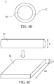
- FIG 4B is a cross sectional view of a signaling yarn according to an embodiment of the present disclosure.
- the signaling yarn 4 comprises a staple fiber 41 and a sheet conductor 42.
- the staple fiber 41 acts as the supporting material to support the sheet conductor 42 which enlaces the staple fiber 41.
- the sheet conductor 42 enlaces a surrounding surface of the staple fiber 41 by taking a spiral course. That the sheet conductor 42 enlaces a surrounding surface of the staple fiber 41 by taking a spiral course can increase the anti-tear strength of the signaling yarn 4.
- the anti-tear strength of the signaling yarn 4 can be further increased by selecting the strength of the staple fiber 41 and/or an aspect ratio of a cross section of the sheet conductor 42 corresponding to the spiral course.
- the strength of the staple fiber 41 is selected to be 30 strands, and the aspect ratio of the cross section of the sheet conductor 42 corresponding to the spiral course is selected to be about 20, but the present disclosure is not limited thereto.
- the staple fiber 41 may have the strength of 26, 28, or 40 strands, or the aspect ratio of the cross section of the sheet conductor 42 corresponding to the spiral course may be selected to be between 10 and 30.
- a material of the staple fiber 41 is selected from polyester, polyamides, polyacrylonitriles, polyethylenes, polypropylenes, celluloses, proteins, elastic fibers, poly perfluoroethylene, polyparaphenylene benzoxazole, polyether ketone, carbon and glass fiber, and the present disclosure is not limited thereto.
- the material of the short staple fiber 11 can be selected as needed.
- the material of the sheet conductor 52 is the metal with electric conductivity. It is worth noting that, in FIG. 2 , the metal in the signaling yarns of the first conductive cloths 21, 23 are different from the metal in the signaling yarns of the second conductive cloths 22.
- FIG. 4C is a schematic diagram showing formation of a sheet conductor of a signaling yarn according to an embodiment of the present disclosure.
- a length and a width of the cross section of the sheet conductor 42 are approximately 4X and X/5 respectively, wherein X is a diameter of the circular cross section of the conductive wire 42'.
- the conductive wire 42' is rolled by a rolling miller to form the sheet conductor 42.
- the formation of the sheet conductor 42 is not intended to limit the present disclosure. In other words, there are different implementations of the sheet conductor 42 of the embodiment of the present disclosure.
- FIG. 5 is a plan view of a temperature controllable textile according to another embodiment of the present disclosure.
- the temperature controllable textile 5 comprises two first conductive cloths 51, 53 and a second conductive cloth 52. Sides of the first conductive cloths 51, 53 are in contact with two opposite sides of the second conductive cloth 52, respectively.
- the first conductive cloths 51, 53 electrically connect to the second conductive cloth 52.
- the two sides of the first conductive cloths 51, 53 which are in contact with the second conductive cloth 52 form two junction portions JN1 and JN2 respectively.
- the two junction portions JN1 and JN2 act as a cooling end and a heating end (or the heating end and the cooling end) respectively.
- the junction portions JN1 and JN2 in the temperature controllable textile 5 are lines rather than plans.
- the temperature controllable textile 5 is rolled, such that the two sides of the first conductive cloths 51, 53 which are in contact with the second conductive cloth 52, respectively, the external environment and the object (or living body) whose temperature is to be controlled.
- the insulated heat-conductive film can be selectively disposed in the temperature controllable textile 5 as needed.
- the first conductive cloths 51, 53 and the second conductive cloth 52 can be formed by weaving signaling yarns, respectively, and then the first conductive cloths 51, 53 and the second conductive cloth 52 are bound to form the temperature controllable textile 5 by stitching, adhesion or the like.
- the metal of the signaling yarns of the first conductive cloths 51, 53 is not identical to the metal of the signaling yarns of the second conductive cloths 52.
- the first conductive cloths 51, 53 and the second conductive cloth 52 in the embodiment can be an integrally formed cloth which is formed by weaving a plurality of composite signaling yarns having different metals therein (to be described in detail later.)
- FIG. 6A is a three-dimensional diagram of a composite signaling yarn according to an embodiment of the present disclosure
- FIG 6B is a cross sectional view of a composite signaling yarn according to an embodiment of the present disclosure.
- the composite signaling yarn 6 comprises a staple fiber 61 and a composite sheet conductor 62, wherein the staple fiber 61 acts as a supporting material with the material and strength as mentioned above.
- the composite sheet conductor 62 enlaces a surrounding surface of the staple fiber 61 by taking a spiral course.
- FIG. 6C is a schematic diagram showing a composite sheet conductor of a composite signaling yarn according to an embodiment of the present disclosure.
- the composite sheet conductor 62 is sheet formed by connecting the sheet conductors 621 through 623 in sequence, wherein the metals of sheet conductors 621 and the 623 are the same one, but different from that of the sheet conductor 622.
- the locations of the sheet conductors 621 through 623 define the locations of the first conductive cloth 51, the second conductive cloth 52 and the first conductive cloth 53 in FIG. 5 .
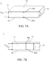
- FIG. 7A is a three-dimensional diagram of a temperature controllable textile according to an embodiment of the present disclosure
- FIG. 7B is a cross sectional view of a temperature controllable textile according to an embodiment of the present disclosure.
- the temperature controllable textile 7 comprises a first conductive cloth 71, a second conductive cloth 72 and two insulated heat-conductive films 73, 74.
- the metal of the first conductive cloth 71 is not the same as that of the second conductive cloth 72.
- the first conductive cloth 71 and the second conductive cloth 72 have a thickness T, for example, larger than or equal to 1 millimeter.
- the side surface of the first conductive cloth 71 is in contact with the side surface of the second conductive cloth 72, and the first conductive cloth 71 electrically connects to the second conductive cloth 72, thus forming two junction portions JN1 and JN2 on the contacting side surfaces.
- the insulated heat-conductive films 73, 74 respectively disposed on the top surfaces of the first conductive cloth 71 and the second conductive cloth 72 and under the bottom surfaces of the first conductive cloth 71 and the second conductive cloth 72.
- junction portions JN1 and JN2 act as a cooling end and a heating end (or the heating end and the cooling end), respectively.
- the junction portions JN1 and JN2 of the temperature controllable textile 7 are lines rather than plans.
- the first conductive cloth 71 is in the number of one.
- the first conductive cloth 71 and the second conductive cloth 72 are formed by weaving signaling yarns respectively, and the first conductive cloth 71 is bound to the second conductive cloth 72 to form the temperature controllable textile 7 by adhesion, stitching or the like.
- the metal of the signaling yarns of the first conductive cloth 71 is not the same as that of the signaling yarns of the second conductive cloth 72.
- first conductive cloth 71 and the second conductive cloth 72 in the embodiment can be an integrally formed cloth formed by weaving composite signaling yarns, wherein each composite signaling yarn have different metals therein.
- the implementation of the composite signaling yarn is similar to the implementation of the composite signaling yarn of FIG. 6A through FIG. 6C , but the composite sheet conductor herein is merely formed by connecting two sheet conductors having different metals.
- the temperature controllable textile provided by the embodiment of the present disclosure can have a cooling end and a heating end for controlling the temperature of the object or the living body, wherein junction portions formed between the at least one first conductive cloth and the second conductive cloth of the temperature controllable textile act as the cooling end and the heating end respectively.
- the temperature controllable textile has the water washable and anti-tear characteristics and can be a part of the wearable assembly, thereby allowing the wearer to wash the wearable assembly smoothly and safely.
- the temperature controllable textile can be in the form of the textile but is not perceived as a foreign body by the wearer, and thus wearing the wearable assembly formed from the temperature controllable textile is a satisfactory wearing experience for the wearer.
Landscapes
- Engineering & Computer Science (AREA)
- Textile Engineering (AREA)
- Environmental & Geological Engineering (AREA)
- Health & Medical Sciences (AREA)
- General Health & Medical Sciences (AREA)
- Physical Education & Sports Medicine (AREA)
- Mechanical Engineering (AREA)
- Chemical & Material Sciences (AREA)
- Inorganic Chemistry (AREA)
- Professional, Industrial, Or Sporting Protective Garments (AREA)
- Woven Fabrics (AREA)
Abstract
Description
- The present disclosure relates to a textile, in particular, to a temperature controllable textile which is dedicated to cooling, and to a wearable assembly having the temperature controllable textile.
- As the technology advances, many enterprises try to incorporate electronic components into clothes to form smart clothes. The smart clothes not only measure physiological signals of wearers (i.e. users), but also heat the wearers. Most of the smart clothes are formed from chips, yarns, electric wires (such as enameled wires) and resistors. The electric wires are embedded or weaved in textiles formed by weaving the yarns, and the electric wires are electrically connected to the resistors and the chips. The electric wires can further connect to external power supply to supply power to the resistors and the chips. The chips each have a controller and a sensor for measuring the physiological signal. When the resistors receive the electricity, the received electricity is converted to the thermal energy, so as to heat the smart clothes. Thus, by heating the smart clothes, the smart clothes prevent the wearers in a cold environment from catching cold or feeling cold.
- Specific materials are required to achieve cooling indirectly in a hot environment. However, the specific materials are not used in forming the textiles of the smart clothes. As a result, the conventional smart clothes are seldom capable of cooling.
- There are several conventional cooling techniques. For example, air compressors compress air to decrease air temperature, thereby achieving cooling. However, air compressors are too bulky to be integrated into the textiles or the smart clothes. Another cooling technique is based on Peltier effect and described below.
- When a current passes an interface between two different conductors, the interface absorbs heat from the outside, or releases heat to the outside, and this is known as "Peltier effect". Referring to
FIG. 1A and FIG. 1B, FIG. 1A is schematic diagram showing a cooling device operating by Peltier effect, andFIG. 1B is an equivalent circuit diagram of the cooling device ofFIG. 1A . Thecooling device 1 comprises twometals metals metal 11, respectively. - Since the materials of the
metals metals 11, 12 (i.e. two side interfaces of themetals 11, 12) to induce a temperature deviation. Thus, the junction portions JN1 and JN2 absorb and release heat respectively. Alternatively, the junction portions JN1 and JN2 release and absorb heat respectively. It is worth noting that whether the junction portions JN1 and JN2 absorb and release heat, respectively, or release and absorb heat, depends on Seebeck coefficients of themetals - Since the above cooling devices lack water washable and anti-tear characteristics and are simply applied to rigid devices, they cannot act as temperature controllable textiles of the smart clothes. Further, if the above cooling devices are directly disposed in the smart clothes but no consideration is given as to whether the above cooling devices have the water washable and anti-tear characteristics, the formed smart clothes may be perceived as a foreign body by the wearers to the detriment of user experiences.
- To achieve an objective of an embodiment of the present disclosure, the present disclosure provides a temperature controllable textile having both of a cooling end and a heating end, so as to cool or heat a living body (such as, a human being, an animal and a plant) or an object, through the cooling end or the heating end.
- According to at least one embodiment of the present disclosure, the present disclosure provides a temperature controllable textile comprising two first conductive cloths and a second conductive cloth. The two first conductive cloths each have a first metal. The second conductive cloth having a second metal not identical to the first metal is disposed between the two first conductive cloths. The second conductive cloth is in contact with and electrically connected to the two first conductive cloths, to form two junction portions. When a negative end and a positive end of a direct current power electrically connect to the two first conductive cloths, respectively, the two junction portions form a cooling end and a heating end, respectively.
- Optionally, a top surface and a bottom surface of the second conductive cloth are in contact with a bottom surface of one of the first conductive cloths and a top surface of the other first conductive cloth, respectively.
- Optionally, the temperature controllable textile further comprises two insulated heat-conductive films disposed on a top surface of one of the first conductive cloths and under a bottom surface of the other first conductive cloth, respectively, wherein the top surface of one of the first conductive cloths and the bottom surface of the other first conductive cloth are not in contact with the second conductive cloth.
- Optionally, each of the two first conductive cloths and the second conductive cloth comprises a plurality of signaling yarns, and the signaling yarns each comprise a staple fiber and a sheet conductor. The staple fiber has a strength of 26 to 40 strands and acts as a supporting material. The sheet conductor enlaces a surrounding surface of the staple fiber by taking a spiral course. A material of the sheet conductor included in the signaling yarn of each the first conductive cloth is the first metal, and a material of the sheet conductor included in the signaling yarn of the second conductive cloth is the second metal.
- Optionally, two sides of the second conductive cloth are in contact with a side of one of the first conductive cloths and a side of the other first conductive cloth, respectively.
- Optionally, the two first conductive cloths and the second conductive cloth are an integrally formed cloth, wherein the integrally formed cloth comprises a plurality of composite signaling yarns, and the composite signaling yarn comprises a staple fiber and a composite sheet conductor. The staple fiber having a strength of 26 to 40 strands acts as a supporting material. The composite sheet conductor enlaces a surrounding surface of the staple fiber by taking a spiral course. The composite sheet conductor is formed by connecting a sheet conductor of the first metal, a sheet conductor of the second metal and another sheet conductor of the first metal in sequence.
- According to at least one embodiment of the present disclosure, the present disclosure provides a temperature controllable textile comprising a first conductive cloth and a second conductive cloth. The first conductive cloth has a first metal. The second conductive cloth has a second metal not identical to the first metal. Both of the first conductive cloth and the second conductive cloth have a thickness. A side surface of the first conductive cloth is in contact with a side surface of the second conductive cloth. The first conductive cloth electrically connects to the second conductive cloth, to form two junction portions. When a negative end and a positive end of a direct current power electrically connect to a top surface and a bottom surface of the first conductive cloth, respectively, the two junction portions form a cooling end and a heating end, respectively.
- Optionally, the temperature controllable textile according further comprises two insulated heat-conductive films disposed on top surfaces of the first and second conductive cloths and under bottom surface of the first and second conductive cloths, respectively.
- Optionally, the first conductive cloth and the second conductive cloth are an integrally formed cloth, wherein the integrally formed cloth comprises a plurality of composite signaling yarns, and the composite signaling yarn comprises a staple fiber and a composite sheet conductor. The staple fiber having a strength of 26 to 40 strands acts as a supporting material. The composite sheet conductor enlaces a surrounding surface of the staple fiber by taking a spiral course. The composite sheet conductor is formed by connecting a sheet conductor of the first metal and a sheet conductor of the second metal in sequence.
- According to at least one embodiment of the present disclosure, the present disclosure provides wearable assembly comprising any one of the above temperature controllable textiles.
- To sum up, the present disclosure provides a temperature controllable textile having a cooling end and a heating end, and the temperature controllable textile is able to increase or decrease the temperature of the living body or the object, in the different environments. In addition, the temperature controllable textile is not perceived as a foreign body by the wearer, and thus wearing the wearable assembly formed from the temperature controllable textile is a satisfactory wearing experience for the wearer.
- In order that the present disclosure may be better understood and readily carried into effect, certain embodiments of the present disclosure will now be described with reference to the accompanying drawings, wherein:
-
FIG. 1A (Related Art) is schematic diagram showing a cooling device utilizing Peltier effect; -
FIG. 1B (Related Art) is an equivalent circuit diagram of the cooling device ofFIG. 1A ; -
FIG. 2 is an explosive diagram of a temperature controllable textile according to an embodiment of the present disclosure; -
FIG. 3 is a schematic diagram showing the application of the temperature controllable textile for the wearable assembly according to an embodiment of the present disclosure; -
FIG. 4A is a three-dimensional diagram of a signaling yarn according to an embodiment of the present disclosure; -
FIG. 4B is a cross sectional view of a signaling yarn according to an embodiment of the present disclosure; -
FIG. 4C is a schematic diagram showing formation of a sheet conductor of a signaling yarn according to an embodiment of the present disclosure; -
FIG. 5 is a plan view of a temperature controllable textile according to another embodiment of the present disclosure; -
FIG. 6A is a three-dimensional diagram of a composite signaling yarn according to an embodiment of the present disclosure; -
FIG. 6B is a cross sectional view of a composite signaling yarn according to an embodiment of the present disclosure; -
FIG. 6C is a schematic diagram showing a composite sheet conductor of a composite signaling yarn according to an embodiment of the present disclosure; -
FIG. 7A is a three-dimensional diagram of a temperature controllable textile according to an embodiment of the present disclosure; and -
FIG. 7B is a cross sectional view of a temperature controllable textile according to an embodiment of the present disclosure. - To make it easier for the examiner to understand the objects, characteristics and effects of this present disclosure, embodiments together with the attached drawings for the detailed description of the present disclosure are provided.
- The present disclosure provides a temperature controllable textile which has the water washable and anti-tear characteristics and can be stitched to other textile, so as to form a part of a wearable assembly (such as, smart clothes, smart shoes, smart pant, wristbands or kneecaps). Furthermore, the temperature controllable textile is not only used to form the wearable assembly, but also dedicated for controlling a temperature of a crop, an electronic equipment, a farm animal or other object or living body.
- In the embodiment of the present disclosure, the temperature controllable textile has at least one first conductive cloth and a second conductive cloth, wherein the at least one first conductive cloth has a first metal, the second conductive cloth has a second metal, and the first metal is not identical to the second metal (i.e. having different Seebeck coefficients.) The at least one first conductive cloth and the second conductive cloth have two junction portions therebetween. A positive end and a negative end of a direct current power electrically connect to the at least one first conductive cloth. The positive end and the negative end of the direct current power correspond to the two junction portions such that the two junction portions act as a cooling end and a heating end, respectively.
- In an embodiment, the at least one first conductive cloth is in the number of two. One of the two first conductive cloths is disposed on and in contact with a top surface of the second conductive cloth while the other one of the two first conductive cloth is disposed under and in contact with a bottom surface of the second conductive cloth. The two first conductive cloths electrically connect to the second conductive cloth. When the positive end and the negative end of the direct current power electrically connect to the two first conductive cloths respectively, the top surface and the bottom surface of second conductive cloth act as the two junction portions, respectively, which in turn act as a cooling end and a heating end respectively (or the heating end and the cooling end), such that the two junction portions absorb and release heat respectively (or release and absorb heat.) Each of the two first conductive cloths and the second conductive cloth in the embodiment can be formed by weaving signaling yarns formed of different metals, respectively.
- In another embodiment, the at least one first conductive cloth is in the number of two. Two sides of the two first conductive cloth are disposed on and in contact with the two opposite sides of the second conductive cloth, respectively. The two first conductive cloth electrically connect to the second conductive cloth. When the positive end and the negative end of the direct current power electrically connect to the two first conductive cloths, respectively, the two opposite sides of the second conductive cloth act as the two junction portions acting as a cooling end and a heating end, respectively (or the heating end and the cooling end), such that the two junction portions absorb and release heat (or release and absorb heat), respectively. Each of the two first conductive cloths and the second conductive cloth in the embodiment can be formed by weaving the signaling yarns formed of different metals, respectively. Alternatively, the two first conductive cloths and the second conductive cloth are an integrally formed cloth, and the internally formed cloth is formed by weaving composite signaling yarns, wherein the composite signaling yarns each have different metals.
- In another embodiment, the at least one first conductive cloth is in the number of one. A side surface of the first conductive cloth is in contact with a side surface of the second conductive cloth. The first conductive cloth electrically connects to the second conductive cloth. The first conductive cloth and the second conductive cloth have a thickness, for example, larger than 1 millimeter. When the positive end and the negative end of the direct current power electrically connect to a top surface and a bottom surface of the first conductive cloth respectively, an upper portion and a lower portion of the side surface of the first conductive cloth (the second conductive cloth) act as the two junction portions respectively. The two junction portions act as a cooling end and a heating end (or the heating end and the cooling end), respectively, such that the two junction portions absorb and release heat (or release and absorb heat) respectively. The first conductive cloth and the second conductive cloth in the embodiment can be formed by weaving the signaling yarns formed of different metals, respectively. Alternatively, the first conductive cloth and the second conductive cloth are the integrally formed cloth, and the integrally formed cloth is formed by weaving the composite signaling yarns, wherein the composite signaling yarns each have different metals.
- Next, implementation details of the temperature controllable textile can be illustrated accompanying with the drawings. However, it is worth noting that the following embodiments are not intended to limit the present disclosure, and the drawings are schematic. Therefore, dimensions of the components and materials of the components are not intended to limit the present disclosure.
- Referring to
FIG. 2, FIG. 2 is an explosive diagram of a temperature controllable textile according to an embodiment of the present disclosure. The temperaturecontrollable textile 2 comprises two firstconductive cloths conductive cloth 22 and two insulated heat-conductive films conductive cloth 21 is in contact with the bottom surface of the secondconductive cloth 22, and the firstconductive cloth 21 electrically connects to the secondconductive cloth 22. A bottom surface of the firstconductive cloth 23 is in contact with a top surface of the secondconductive cloth 22, and the firstconductive cloth 23 electrically connects to the secondconductive cloth 22. The insulated heat-conductive film 24 is disposed under a bottom surface of the firstconductive cloth 21 while the insulated heat-conductive film 24 is disposed on a top surface of the firstconductive cloth 22. - The first
conductive cloths conductive cloth 22 has a metal different from that of the firstconductive cloths conductive cloths conductive cloth 22. In addition, the firstconductive cloths conductive cloth 22 and the insulated heat-conductive films controllable textile 2 by adhesion, stitching or the like. The temperaturecontrollable textile 2 can further be adhered, stitched or connected to other objects or textiles. - When a positive end and a negative end of a direct current power VDC electrically connect to the first
conductive cloths conductive clothes conductive cloth 22 act as a cooling end and a heating end (or the heating end and the cooling end) respectively. In the embodiment, the two junction portions are the top surface of the firstconductive cloth 21 and the bottom surface of the first conductive cloth 23 (or the top surface and the bottom surface of the second conductive cloth 22) respectively, and thus the firstconductive clothes conductive cloths conductive cloths 22, and/or the polarity of the direct current power VDC. - In the embodiment, the two insulated heat-
conductive films conductive films - In the embodiment, the first
conductive cloths conductive cloth 22 are formed by weaving signaling yarns formed from different metals. The signaling yarns are illustrated byFIG. 4A through FIG. 4C and described later. - Referring to
FIG. 3, FIG. 3 is a schematic diagram showing the application of the temperature controllable textile for the wearable assembly according to an embodiment of the present disclosure. In the embodiment, the wearable assembly can be the smart clothes which have a temperaturecontrollable textile 2 and a textile 3, wherein the textile 3 is stitched to the temperaturecontrollable textile 2. The location of the temperaturecontrollable textile 2 is corresponding to the location of a wrist of the hand H. The inside of the temperature controllable textile 2 (the side in contact with the wrist) can be designed to be the cooling end, and the outside of the temperature controllable textile 2 (the side not in contact with the wrist) can be designed to be the heating end, thus making the wearer feel cool in the hot environment. By contrast, the outside of the temperature controllable textile 2 (the side not in contact with the wrist) can be designed to be the cooling end, and the inside of the temperature controllable textile 2 (the side in contact with the wrist) can be designed to be the heating end, thus making the wearer feel warm in the cold environment. The way of determining the cooling end and the heating end is illustrated above. As shown inFIG. 2 , whether the two junction portions act as the cooling end and the heating end, or the heating end and the cooling end, respectively, depends on Seebeck coefficients of the firstconductive cloths conductive cloths 22, and/or the polarity of the direct current power VDC. If the positive end and the negative end of the direct current power VDC are changed to electrically connect to the firstconductive cloths - Next, referring to
FIG. 4A andFIG. 4B ,FIG. 4A is a three-dimensional diagram of a signaling yarn according to an embodiment of the present disclosure, andFIG 4B is a cross sectional view of a signaling yarn according to an embodiment of the present disclosure. The signalingyarn 4 comprises astaple fiber 41 and asheet conductor 42. Thestaple fiber 41 acts as the supporting material to support thesheet conductor 42 which enlaces thestaple fiber 41. Specifically, thesheet conductor 42 enlaces a surrounding surface of thestaple fiber 41 by taking a spiral course. That thesheet conductor 42 enlaces a surrounding surface of thestaple fiber 41 by taking a spiral course can increase the anti-tear strength of the signalingyarn 4. - Optionally, the anti-tear strength of the signaling
yarn 4 can be further increased by selecting the strength of thestaple fiber 41 and/or an aspect ratio of a cross section of thesheet conductor 42 corresponding to the spiral course. In this embodiment, the strength of thestaple fiber 41 is selected to be 30 strands, and the aspect ratio of the cross section of thesheet conductor 42 corresponding to the spiral course is selected to be about 20, but the present disclosure is not limited thereto. For example, thestaple fiber 41 may have the strength of 26, 28, or 40 strands, or the aspect ratio of the cross section of thesheet conductor 42 corresponding to the spiral course may be selected to be between 10 and 30. - In the embodiment, a material of the
staple fiber 41 is selected from polyester, polyamides, polyacrylonitriles, polyethylenes, polypropylenes, celluloses, proteins, elastic fibers, poly perfluoroethylene, polyparaphenylene benzoxazole, polyether ketone, carbon and glass fiber, and the present disclosure is not limited thereto. The material of theshort staple fiber 11 can be selected as needed. Additionally, the material of thesheet conductor 52 is the metal with electric conductivity. It is worth noting that, inFIG. 2 , the metal in the signaling yarns of the firstconductive cloths conductive cloths 22. - Further, referring to
FIG. 4C, FIG. 4C is a schematic diagram showing formation of a sheet conductor of a signaling yarn according to an embodiment of the present disclosure. In the embodiment, a length and a width of the cross section of thesheet conductor 42 are approximately 4X and X/5 respectively, wherein X is a diameter of the circular cross section of the conductive wire 42'. The conductive wire 42' is rolled by a rolling miller to form thesheet conductor 42. However, the formation of thesheet conductor 42 is not intended to limit the present disclosure. In other words, there are different implementations of thesheet conductor 42 of the embodiment of the present disclosure. - Further, referring to
FIG. 5, FIG. 5 is a plan view of a temperature controllable textile according to another embodiment of the present disclosure. The temperaturecontrollable textile 5 comprises two firstconductive cloths conductive cloth 52. Sides of the firstconductive cloths conductive cloth 52, respectively. The firstconductive cloths conductive cloth 52. The two sides of the firstconductive cloths conductive cloth 52 form two junction portions JN1 and JN2 respectively. When a positive end and a negative end of the direct current power VDC electrically connect to the firstconductive cloths - Being different from the embodiment of
FIG. 2 , the junction portions JN1 and JN2 in the temperaturecontrollable textile 5 are lines rather than plans. When using the temperaturecontrollable textile 5, the temperaturecontrollable textile 5 is rolled, such that the two sides of the firstconductive cloths conductive cloth 52, respectively, the external environment and the object (or living body) whose temperature is to be controlled. In addition, in the embodiment, the insulated heat-conductive film can be selectively disposed in the temperaturecontrollable textile 5 as needed. - In the embodiment, the first
conductive cloths conductive cloth 52 can be formed by weaving signaling yarns, respectively, and then the firstconductive cloths conductive cloth 52 are bound to form the temperaturecontrollable textile 5 by stitching, adhesion or the like. The metal of the signaling yarns of the firstconductive cloths conductive cloths 52. In addition, the firstconductive cloths conductive cloth 52 in the embodiment can be an integrally formed cloth which is formed by weaving a plurality of composite signaling yarns having different metals therein (to be described in detail later.) - Referring to
FIG. 6A andFIG. 6B ,FIG. 6A is a three-dimensional diagram of a composite signaling yarn according to an embodiment of the present disclosure, andFIG 6B is a cross sectional view of a composite signaling yarn according to an embodiment of the present disclosure. The composite signaling yarn 6 comprises astaple fiber 61 and acomposite sheet conductor 62, wherein thestaple fiber 61 acts as a supporting material with the material and strength as mentioned above. Thecomposite sheet conductor 62 enlaces a surrounding surface of thestaple fiber 61 by taking a spiral course. - Further, the details of the composite sheet conductor are illustrated. Referring to
FIG. 6C, FIG. 6C is a schematic diagram showing a composite sheet conductor of a composite signaling yarn according to an embodiment of the present disclosure. Thecomposite sheet conductor 62 is sheet formed by connecting thesheet conductors 621 through 623 in sequence, wherein the metals ofsheet conductors 621 and the 623 are the same one, but different from that of thesheet conductor 622. The locations of thesheet conductors 621 through 623 define the locations of the firstconductive cloth 51, the secondconductive cloth 52 and the firstconductive cloth 53 inFIG. 5 . - Next, referring to
FIG. 7A and FIG. 7B, FIG. 7A is a three-dimensional diagram of a temperature controllable textile according to an embodiment of the present disclosure, andFIG. 7B is a cross sectional view of a temperature controllable textile according to an embodiment of the present disclosure. The temperaturecontrollable textile 7 comprises a firstconductive cloth 71, a secondconductive cloth 72 and two insulated heat-conductive films conductive cloth 71 is not the same as that of the secondconductive cloth 72. The firstconductive cloth 71 and the secondconductive cloth 72 have a thickness T, for example, larger than or equal to 1 millimeter. The side surface of the firstconductive cloth 71 is in contact with the side surface of the secondconductive cloth 72, and the firstconductive cloth 71 electrically connects to the secondconductive cloth 72, thus forming two junction portions JN1 and JN2 on the contacting side surfaces. The insulated heat-conductive films conductive cloth 71 and the secondconductive cloth 72 and under the bottom surfaces of the firstconductive cloth 71 and the secondconductive cloth 72. When a positive end and a negative end of the direct current power VDC electrically connects respectively with the top surface and the bottom surface of the firstconductive cloth 71, the junction portions JN1 and JN2 act as a cooling end and a heating end (or the heating end and the cooling end), respectively. - Being different from the embodiment of
FIG. 2 , the junction portions JN1 and JN2 of the temperaturecontrollable textile 7 are lines rather than plans. Further, being different from the embodiments ofFIG. 2 andFIG. 5 , the firstconductive cloth 71 is in the number of one. In the embodiment, the firstconductive cloth 71 and the secondconductive cloth 72 are formed by weaving signaling yarns respectively, and the firstconductive cloth 71 is bound to the secondconductive cloth 72 to form the temperaturecontrollable textile 7 by adhesion, stitching or the like. The metal of the signaling yarns of the firstconductive cloth 71 is not the same as that of the signaling yarns of the secondconductive cloth 72. In addition, the firstconductive cloth 71 and the secondconductive cloth 72 in the embodiment can be an integrally formed cloth formed by weaving composite signaling yarns, wherein each composite signaling yarn have different metals therein. The implementation of the composite signaling yarn is similar to the implementation of the composite signaling yarn ofFIG. 6A through FIG. 6C , but the composite sheet conductor herein is merely formed by connecting two sheet conductors having different metals. - To sum up, the temperature controllable textile provided by the embodiment of the present disclosure can have a cooling end and a heating end for controlling the temperature of the object or the living body, wherein junction portions formed between the at least one first conductive cloth and the second conductive cloth of the temperature controllable textile act as the cooling end and the heating end respectively. The temperature controllable textile has the water washable and anti-tear characteristics and can be a part of the wearable assembly, thereby allowing the wearer to wash the wearable assembly smoothly and safely. Moreover, the temperature controllable textile can be in the form of the textile but is not perceived as a foreign body by the wearer, and thus wearing the wearable assembly formed from the temperature controllable textile is a satisfactory wearing experience for the wearer.
- The above is only embodiments of the present disclosure, and these embodiments are not intended to limit the scope of the present disclosure.
Claims (18)
- A temperature controllable textile (2; 5), comprising:two first conductive cloths (21, 23; 51, 53), each having a first metal; anda second conductive cloth (22; 52), having a second metal not identical to the first metal, the second conductive cloth (22; 52) being disposed between the two first conductive cloths (21, 23; 51, 53), the second conductive cloth (22; 52) being in contact with and electrically connected to the two first conductive cloths (21, 23; 51, 53), to form two junction portions;wherein, when a negative end and a positive end of a direct current power (VDC) electrically connect to the two first conductive cloths (21, 23; 51, 53), respectively, the two junction portions form a cooling end and a heating end, respectively.
- The temperature controllable textile (2; 5) according to claim 1, wherein a top surface and a bottom surface of the second conductive cloth (22; 52) are in contact with a bottom surface of one of the first conductive cloths (21, 23; 51, 53) and a top surface of the other first conductive cloth, respectively.
- The temperature controllable textile (2; 5) according to claim 1, further comprising two insulated heat-conductive films (24, 25) disposed on a top surface of one of the first conductive cloths (21, 23; 51, 53) and under a bottom surface of the other first conductive cloth, respectively, wherein the top surface of one of the first conductive cloths (21, 23; 51, 53) and the bottom surface of the other first conductive cloth are not in contact with the second conductive cloth (22; 52).
- The temperature controllable textile (2; 5) according to claim 2, wherein each of the two first conductive cloths (21, 23; 51, 53) and the second conductive cloth (22; 52) comprises a plurality of signaling yarns (4), and the signaling yarns (4) each comprise:a staple fiber (41), having a strength of 26 to 40 strands, acting as a supporting material; anda sheet conductor (42), enlacing a surrounding surface of the staple fiber (41) by taking a spiral course;wherein a material of the sheet conductor (42) included in the signaling yarn (4) of each the first conductive cloth is the first metal, and a material of the sheet conductor (42) included in the signaling yarn (4) of the second conductive cloth (22; 52) is the second metal.
- The temperature controllable textile (2; 5) according to claim 1, wherein two sides of the second conductive cloth (22; 52) are in contact with a side of one of the first conductive cloths (21, 23; 51, 53) and a side of the other first conductive cloth, respectively.
- The temperature controllable textile (2; 5) according to claim 5, wherein the two first conductive cloths (21, 23; 51, 53) and the second conductive cloth (22; 52) are an integrally formed cloth, wherein the integrally formed cloth comprises a plurality of composite signaling yarns (6), and the composite signaling yarn (6) comprises:a staple fiber (61), having a strength of 26 to 40 strands, acting as a supporting material; anda composite sheet conductor (62), enlacing a surrounding surface of the staple fiber (61) by taking a spiral course;wherein the composite sheet conductor (62) is formed by connecting a sheet conductor (621) of the first metal, a sheet conductor (622) of the second metal and another sheet conductor (623) of the first metal in sequence.
- A temperature controllable textile (7), comprising:a first conductive cloth (71), having a first metal; anda second conductive cloth (72), having a second metal not identical to the first metal, wherein the first conductive cloth (71) and the second conductive cloth (72) have a thickness, and a side surface of the first conductive cloth (71) is in contact with a side surface of the second conductive cloth (72), with the first conductive cloth (71) electrically connecting to the second conductive cloth (72), to form two junction portions (JN1, JN2);wherein, when a negative end and a positive end of a direct current power (VDC) electrically connect to a top surface and a bottom surface of the first conductive cloth (71), respectively, the two junction portions (JN1, JN2) form a cooling end and a heating end, respectively.
- The temperature controllable textile (7) according to claim 7, further comprising two insulated heat-conductive films (73, 74), disposed on top surfaces of the first and second conductive cloths (71, 72) and under bottom surfaces of the first and second conductive cloths (71, 72), respectively.
- The temperature controllable textile (7) according to claim 8, wherein the first conductive cloth (71) and the second conductive cloth (72) are an integrally formed cloth, wherein the integrally formed cloth comprises a plurality of composite signaling yarns, and the composite signaling yarns comprise:a staple fiber, having a strength of 26 to 40 strands, acting as a supporting material; anda composite sheet conductor, enlacing a surrounding surface of the staple fiber by taking a spiral course;wherein the composite sheet conductor is formed by connecting a sheet conductor of the first metal and a sheet conductor of the second metal in sequence.
- A wearable assembly, comprising the temperature controllable textile (2; 5) according to claim 1.
- A wearable assembly, comprising the temperature controllable textile (2; 5) according to claim 2.
- A wearable assembly, comprising the temperature controllable textile (2; 5) according to claim 3.
- A wearable assembly, comprising the temperature controllable textile (2; 5) according to claim 4.
- A wearable assembly, comprising the temperature controllable textile (2; 5) according to claim 5.
- A wearable assembly, comprising the temperature controllable textile (2; 5) according to claim 6.
- A wearable assembly, comprising the temperature controllable textile (7) according to claim 7.
- A wearable assembly, comprising the temperature controllable textile (7) according to claim 8.
- A wearable assembly, comprising the temperature controllable textile (7) according to claim 9.
Applications Claiming Priority (1)
| Application Number | Priority Date | Filing Date | Title |
|---|---|---|---|
| TW107114589A TWI740033B (en) | 2018-04-27 | 2018-04-27 | Temperature controllable textile and wearable assembly thereof |
Publications (2)
| Publication Number | Publication Date |
|---|---|
| EP3561888A1 true EP3561888A1 (en) | 2019-10-30 |
| EP3561888B1 EP3561888B1 (en) | 2021-03-17 |
Family
ID=66597460
Family Applications (1)
| Application Number | Title | Priority Date | Filing Date |
|---|---|---|---|
| EP19170773.6A Not-in-force EP3561888B1 (en) | 2018-04-27 | 2019-04-24 | Temperature controllable textile and wearable assembly thereof |
Country Status (3)
| Country | Link |
|---|---|
| US (1) | US11044956B2 (en) |
| EP (1) | EP3561888B1 (en) |
| TW (1) | TWI740033B (en) |
Citations (5)
| Publication number | Priority date | Publication date | Assignee | Title |
|---|---|---|---|---|
| FR2080153A5 (en) * | 1970-02-25 | 1971-11-12 | Saint Gobain | |
| US3661653A (en) * | 1966-06-14 | 1972-05-09 | Arco Nuclear Co | Thermoelectric apparatus |
| JPH109969A (en) * | 1996-06-26 | 1998-01-16 | Kanebo Ltd | Thermoelectric conversion fabric |
| US20040025930A1 (en) * | 2000-12-01 | 2004-02-12 | Edouard Serras | Method for manufacturing thermoelectric converters |
| CN107201585A (en) * | 2017-06-07 | 2017-09-26 | 丹阳市斯鲍特体育用品有限公司 | A kind of fencing metallic plastron fabric flat filament fasciated yarn and preparation method thereof |
Family Cites Families (8)
| Publication number | Priority date | Publication date | Assignee | Title |
|---|---|---|---|---|
| FR2899999B1 (en) * | 2006-04-13 | 2008-06-27 | Commissariat Energie Atomique | THERMOELECTRIC STRUCTURE AND USE OF THE THERMOELECTRIC STRUCTURE FOR FORMING A TEXTILE STRUCTURE |
| EP3270736B1 (en) * | 2015-03-17 | 2018-12-19 | Dreamwell, Ltd. | Temperature control mattress with thermoelectric fabric |
| US10797215B2 (en) * | 2015-09-08 | 2020-10-06 | Boris Russ | Graded thermoelectric materials |
| CA2916131A1 (en) * | 2015-12-22 | 2017-06-22 | Jannatec Technologies | System for regulating body temperature of a subject |
| US20180014585A1 (en) * | 2016-07-17 | 2018-01-18 | David Requena Polonio | Temperature controlled garment |
| US11152556B2 (en) * | 2017-07-29 | 2021-10-19 | Nanohmics, Inc. | Flexible and conformable thermoelectric compositions |
| JP6939364B2 (en) * | 2017-10-03 | 2021-09-22 | 信越化学工業株式会社 | Light-transmitting heat-conducting resin sheet and its manufacturing method |
| WO2019173591A1 (en) * | 2018-03-07 | 2019-09-12 | The Regents Of The University Of Michigan | Thermoelectric thread for a heating and/or cooling device |
-
2018
- 2018-04-27 TW TW107114589A patent/TWI740033B/en not_active IP Right Cessation
- 2018-10-02 US US16/149,786 patent/US11044956B2/en not_active Expired - Fee Related
-
2019
- 2019-04-24 EP EP19170773.6A patent/EP3561888B1/en not_active Not-in-force
Patent Citations (5)
| Publication number | Priority date | Publication date | Assignee | Title |
|---|---|---|---|---|
| US3661653A (en) * | 1966-06-14 | 1972-05-09 | Arco Nuclear Co | Thermoelectric apparatus |
| FR2080153A5 (en) * | 1970-02-25 | 1971-11-12 | Saint Gobain | |
| JPH109969A (en) * | 1996-06-26 | 1998-01-16 | Kanebo Ltd | Thermoelectric conversion fabric |
| US20040025930A1 (en) * | 2000-12-01 | 2004-02-12 | Edouard Serras | Method for manufacturing thermoelectric converters |
| CN107201585A (en) * | 2017-06-07 | 2017-09-26 | 丹阳市斯鲍特体育用品有限公司 | A kind of fencing metallic plastron fabric flat filament fasciated yarn and preparation method thereof |
Also Published As
| Publication number | Publication date |
|---|---|
| US11044956B2 (en) | 2021-06-29 |
| US20190328055A1 (en) | 2019-10-31 |
| TW201945607A (en) | 2019-12-01 |
| EP3561888B1 (en) | 2021-03-17 |
| TWI740033B (en) | 2021-09-21 |
Similar Documents
| Publication | Publication Date | Title |
|---|---|---|
| JP5367144B2 (en) | Conductive pad and manufacturing method thereof | |
| US8133264B1 (en) | Therapeutic heating sleeve | |
| CN107771040A (en) | Textile or fabric with attached flexible and coordinated light source device | |
| TWI675628B (en) | Functional device with cloth | |
| US20150272236A1 (en) | Electrically-Heated Clothing/Pants and Its Accessories | |
| JP6836645B2 (en) | Conductive composite sheet | |
| US20180014585A1 (en) | Temperature controlled garment | |
| US20150382402A1 (en) | Electrically-Heated Clothing/Pants and Its Accessories with Silicone Rubber Heaters | |
| US20190029558A1 (en) | Module for detecting electrical signals from body skin | |
| Kayacan et al. | Implementation of steel-based fabric panels in a heated garment design | |
| JP2019220247A (en) | Terminal connection structure and terminal connection method | |
| Bahadir et al. | A wearable heating system with a controllable e-textile-based thermal panel | |
| Thilagavathi et al. | Development and characterization of electric heating fabric based on silver coated nylon yarn | |
| EP3561888B1 (en) | Temperature controllable textile and wearable assembly thereof | |
| KR101471271B1 (en) | Temperature Responsive Fiber Structure | |
| US11019856B2 (en) | Temperature controllable textile and wearable assembly thereof | |
| CN108182986B (en) | Electrical connections for wearable and other articles | |
| CN110574977A (en) | Temperature-controlled fabrics and wearables made from them | |
| KR102125395B1 (en) | Electric conduction planar element | |
| CN110574978A (en) | Temperature-controlled fabrics and wearables made from them | |
| Kumar et al. | Interactive smart textile garment with automatic temperature control and monitoring | |
| RU2860007C1 (en) | Multi-layer protective clothing | |
| KR101715221B1 (en) | Electric heating type jacket | |
| CN217487703U (en) | Wearable insulation equipment of noninductive formula | |
| Jones | The application of temperature sensors into fabric substrates. |
Legal Events
| Date | Code | Title | Description |
|---|---|---|---|
| PUAI | Public reference made under article 153(3) epc to a published international application that has entered the european phase |
Free format text: ORIGINAL CODE: 0009012 |
|
| STAA | Information on the status of an ep patent application or granted ep patent |
Free format text: STATUS: THE APPLICATION HAS BEEN PUBLISHED |
|
| AK | Designated contracting states |
Kind code of ref document: A1 Designated state(s): AL AT BE BG CH CY CZ DE DK EE ES FI FR GB GR HR HU IE IS IT LI LT LU LV MC MK MT NL NO PL PT RO RS SE SI SK SM TR |
|
| AX | Request for extension of the european patent |
Extension state: BA ME |
|
| STAA | Information on the status of an ep patent application or granted ep patent |
Free format text: STATUS: REQUEST FOR EXAMINATION WAS MADE |
|
| 17P | Request for examination filed |
Effective date: 20200424 |
|
| RBV | Designated contracting states (corrected) |
Designated state(s): AL AT BE BG CH CY CZ DE DK EE ES FI FR GB GR HR HU IE IS IT LI LT LU LV MC MK MT NL NO PL PT RO RS SE SI SK SM TR |
|
| GRAP | Despatch of communication of intention to grant a patent |
Free format text: ORIGINAL CODE: EPIDOSNIGR1 |
|
| STAA | Information on the status of an ep patent application or granted ep patent |
Free format text: STATUS: GRANT OF PATENT IS INTENDED |
|
| INTG | Intention to grant announced |
Effective date: 20201105 |
|
| GRAS | Grant fee paid |
Free format text: ORIGINAL CODE: EPIDOSNIGR3 |
|
| GRAA | (expected) grant |
Free format text: ORIGINAL CODE: 0009210 |
|
| STAA | Information on the status of an ep patent application or granted ep patent |
Free format text: STATUS: THE PATENT HAS BEEN GRANTED |
|
| AK | Designated contracting states |
Kind code of ref document: B1 Designated state(s): AL AT BE BG CH CY CZ DE DK EE ES FI FR GB GR HR HU IE IS IT LI LT LU LV MC MK MT NL NO PL PT RO RS SE SI SK SM TR |
|
| REG | Reference to a national code |
Ref country code: GB Ref legal event code: FG4D |
|
| REG | Reference to a national code |
Ref country code: CH Ref legal event code: EP |
|
| REG | Reference to a national code |
Ref country code: DE Ref legal event code: R096 Ref document number: 602019003174 Country of ref document: DE |
|
| REG | Reference to a national code |
Ref country code: IE Ref legal event code: FG4D |
|
| REG | Reference to a national code |
Ref country code: AT Ref legal event code: REF Ref document number: 1373049 Country of ref document: AT Kind code of ref document: T Effective date: 20210415 |
|
| REG | Reference to a national code |
Ref country code: LT Ref legal event code: MG9D |
|
| PG25 | Lapsed in a contracting state [announced via postgrant information from national office to epo] |
Ref country code: NO Free format text: LAPSE BECAUSE OF FAILURE TO SUBMIT A TRANSLATION OF THE DESCRIPTION OR TO PAY THE FEE WITHIN THE PRESCRIBED TIME-LIMIT Effective date: 20210617 Ref country code: BG Free format text: LAPSE BECAUSE OF FAILURE TO SUBMIT A TRANSLATION OF THE DESCRIPTION OR TO PAY THE FEE WITHIN THE PRESCRIBED TIME-LIMIT Effective date: 20210617 Ref country code: FI Free format text: LAPSE BECAUSE OF FAILURE TO SUBMIT A TRANSLATION OF THE DESCRIPTION OR TO PAY THE FEE WITHIN THE PRESCRIBED TIME-LIMIT Effective date: 20210317 Ref country code: GR Free format text: LAPSE BECAUSE OF FAILURE TO SUBMIT A TRANSLATION OF THE DESCRIPTION OR TO PAY THE FEE WITHIN THE PRESCRIBED TIME-LIMIT Effective date: 20210618 Ref country code: HR Free format text: LAPSE BECAUSE OF FAILURE TO SUBMIT A TRANSLATION OF THE DESCRIPTION OR TO PAY THE FEE WITHIN THE PRESCRIBED TIME-LIMIT Effective date: 20210317 |
|
| PGFP | Annual fee paid to national office [announced via postgrant information from national office to epo] |
Ref country code: DE Payment date: 20210419 Year of fee payment: 3 Ref country code: FR Payment date: 20210419 Year of fee payment: 3 |
|
| REG | Reference to a national code |
Ref country code: AT Ref legal event code: MK05 Ref document number: 1373049 Country of ref document: AT Kind code of ref document: T Effective date: 20210317 |
|
| REG | Reference to a national code |
Ref country code: NL Ref legal event code: MP Effective date: 20210317 |
|
| PG25 | Lapsed in a contracting state [announced via postgrant information from national office to epo] |
Ref country code: LV Free format text: LAPSE BECAUSE OF FAILURE TO SUBMIT A TRANSLATION OF THE DESCRIPTION OR TO PAY THE FEE WITHIN THE PRESCRIBED TIME-LIMIT Effective date: 20210317 Ref country code: RS Free format text: LAPSE BECAUSE OF FAILURE TO SUBMIT A TRANSLATION OF THE DESCRIPTION OR TO PAY THE FEE WITHIN THE PRESCRIBED TIME-LIMIT Effective date: 20210317 Ref country code: SE Free format text: LAPSE BECAUSE OF FAILURE TO SUBMIT A TRANSLATION OF THE DESCRIPTION OR TO PAY THE FEE WITHIN THE PRESCRIBED TIME-LIMIT Effective date: 20210317 |
|
| PG25 | Lapsed in a contracting state [announced via postgrant information from national office to epo] |
Ref country code: NL Free format text: LAPSE BECAUSE OF FAILURE TO SUBMIT A TRANSLATION OF THE DESCRIPTION OR TO PAY THE FEE WITHIN THE PRESCRIBED TIME-LIMIT Effective date: 20210317 |
|
| PG25 | Lapsed in a contracting state [announced via postgrant information from national office to epo] |
Ref country code: SM Free format text: LAPSE BECAUSE OF FAILURE TO SUBMIT A TRANSLATION OF THE DESCRIPTION OR TO PAY THE FEE WITHIN THE PRESCRIBED TIME-LIMIT Effective date: 20210317 Ref country code: AT Free format text: LAPSE BECAUSE OF FAILURE TO SUBMIT A TRANSLATION OF THE DESCRIPTION OR TO PAY THE FEE WITHIN THE PRESCRIBED TIME-LIMIT Effective date: 20210317 Ref country code: CZ Free format text: LAPSE BECAUSE OF FAILURE TO SUBMIT A TRANSLATION OF THE DESCRIPTION OR TO PAY THE FEE WITHIN THE PRESCRIBED TIME-LIMIT Effective date: 20210317 Ref country code: EE Free format text: LAPSE BECAUSE OF FAILURE TO SUBMIT A TRANSLATION OF THE DESCRIPTION OR TO PAY THE FEE WITHIN THE PRESCRIBED TIME-LIMIT Effective date: 20210317 Ref country code: LT Free format text: LAPSE BECAUSE OF FAILURE TO SUBMIT A TRANSLATION OF THE DESCRIPTION OR TO PAY THE FEE WITHIN THE PRESCRIBED TIME-LIMIT Effective date: 20210317 |
|
| PG25 | Lapsed in a contracting state [announced via postgrant information from national office to epo] |
Ref country code: IS Free format text: LAPSE BECAUSE OF FAILURE TO SUBMIT A TRANSLATION OF THE DESCRIPTION OR TO PAY THE FEE WITHIN THE PRESCRIBED TIME-LIMIT Effective date: 20210717 Ref country code: SK Free format text: LAPSE BECAUSE OF FAILURE TO SUBMIT A TRANSLATION OF THE DESCRIPTION OR TO PAY THE FEE WITHIN THE PRESCRIBED TIME-LIMIT Effective date: 20210317 Ref country code: RO Free format text: LAPSE BECAUSE OF FAILURE TO SUBMIT A TRANSLATION OF THE DESCRIPTION OR TO PAY THE FEE WITHIN THE PRESCRIBED TIME-LIMIT Effective date: 20210317 Ref country code: PT Free format text: LAPSE BECAUSE OF FAILURE TO SUBMIT A TRANSLATION OF THE DESCRIPTION OR TO PAY THE FEE WITHIN THE PRESCRIBED TIME-LIMIT Effective date: 20210719 Ref country code: PL Free format text: LAPSE BECAUSE OF FAILURE TO SUBMIT A TRANSLATION OF THE DESCRIPTION OR TO PAY THE FEE WITHIN THE PRESCRIBED TIME-LIMIT Effective date: 20210317 |
|
| REG | Reference to a national code |
Ref country code: DE Ref legal event code: R097 Ref document number: 602019003174 Country of ref document: DE |
|
| PG25 | Lapsed in a contracting state [announced via postgrant information from national office to epo] |
Ref country code: LU Free format text: LAPSE BECAUSE OF NON-PAYMENT OF DUE FEES Effective date: 20210424 |
|
| REG | Reference to a national code |
Ref country code: BE Ref legal event code: MM Effective date: 20210430 |
|
| PLBE | No opposition filed within time limit |
Free format text: ORIGINAL CODE: 0009261 |
|
| STAA | Information on the status of an ep patent application or granted ep patent |
Free format text: STATUS: NO OPPOSITION FILED WITHIN TIME LIMIT |
|
| PG25 | Lapsed in a contracting state [announced via postgrant information from national office to epo] |
Ref country code: MC Free format text: LAPSE BECAUSE OF FAILURE TO SUBMIT A TRANSLATION OF THE DESCRIPTION OR TO PAY THE FEE WITHIN THE PRESCRIBED TIME-LIMIT Effective date: 20210317 Ref country code: DK Free format text: LAPSE BECAUSE OF FAILURE TO SUBMIT A TRANSLATION OF THE DESCRIPTION OR TO PAY THE FEE WITHIN THE PRESCRIBED TIME-LIMIT Effective date: 20210317 Ref country code: AL Free format text: LAPSE BECAUSE OF FAILURE TO SUBMIT A TRANSLATION OF THE DESCRIPTION OR TO PAY THE FEE WITHIN THE PRESCRIBED TIME-LIMIT Effective date: 20210317 Ref country code: ES Free format text: LAPSE BECAUSE OF FAILURE TO SUBMIT A TRANSLATION OF THE DESCRIPTION OR TO PAY THE FEE WITHIN THE PRESCRIBED TIME-LIMIT Effective date: 20210317 |
|
| 26N | No opposition filed |
Effective date: 20211220 |
|
| PG25 | Lapsed in a contracting state [announced via postgrant information from national office to epo] |
Ref country code: SI Free format text: LAPSE BECAUSE OF FAILURE TO SUBMIT A TRANSLATION OF THE DESCRIPTION OR TO PAY THE FEE WITHIN THE PRESCRIBED TIME-LIMIT Effective date: 20210317 |
|
| PG25 | Lapsed in a contracting state [announced via postgrant information from national office to epo] |
Ref country code: IT Free format text: LAPSE BECAUSE OF FAILURE TO SUBMIT A TRANSLATION OF THE DESCRIPTION OR TO PAY THE FEE WITHIN THE PRESCRIBED TIME-LIMIT Effective date: 20210317 Ref country code: IE Free format text: LAPSE BECAUSE OF NON-PAYMENT OF DUE FEES Effective date: 20210424 |
|
| PG25 | Lapsed in a contracting state [announced via postgrant information from national office to epo] |
Ref country code: IS Free format text: LAPSE BECAUSE OF FAILURE TO SUBMIT A TRANSLATION OF THE DESCRIPTION OR TO PAY THE FEE WITHIN THE PRESCRIBED TIME-LIMIT Effective date: 20210717 |
|
| PG25 | Lapsed in a contracting state [announced via postgrant information from national office to epo] |
Ref country code: BE Free format text: LAPSE BECAUSE OF NON-PAYMENT OF DUE FEES Effective date: 20210430 |
|
| REG | Reference to a national code |
Ref country code: DE Ref legal event code: R119 Ref document number: 602019003174 Country of ref document: DE |
|
| REG | Reference to a national code |
Ref country code: DE Ref legal event code: R079 Ref document number: 602019003174 Country of ref document: DE Free format text: PREVIOUS MAIN CLASS: H01L0035200000 Ipc: H10N0010854000 |
|
| REG | Reference to a national code |
Ref country code: CH Ref legal event code: PL |
|
| PG25 | Lapsed in a contracting state [announced via postgrant information from national office to epo] |
Ref country code: LI Free format text: LAPSE BECAUSE OF NON-PAYMENT OF DUE FEES Effective date: 20220430 Ref country code: FR Free format text: LAPSE BECAUSE OF NON-PAYMENT OF DUE FEES Effective date: 20220430 Ref country code: DE Free format text: LAPSE BECAUSE OF NON-PAYMENT OF DUE FEES Effective date: 20221103 Ref country code: CH Free format text: LAPSE BECAUSE OF NON-PAYMENT OF DUE FEES Effective date: 20220430 |
|
| PG25 | Lapsed in a contracting state [announced via postgrant information from national office to epo] |
Ref country code: CY Free format text: LAPSE BECAUSE OF FAILURE TO SUBMIT A TRANSLATION OF THE DESCRIPTION OR TO PAY THE FEE WITHIN THE PRESCRIBED TIME-LIMIT Effective date: 20210317 |
|
| PG25 | Lapsed in a contracting state [announced via postgrant information from national office to epo] |
Ref country code: HU Free format text: LAPSE BECAUSE OF FAILURE TO SUBMIT A TRANSLATION OF THE DESCRIPTION OR TO PAY THE FEE WITHIN THE PRESCRIBED TIME-LIMIT; INVALID AB INITIO Effective date: 20190424 |
|
| GBPC | Gb: european patent ceased through non-payment of renewal fee |
Effective date: 20230424 |
|
| PG25 | Lapsed in a contracting state [announced via postgrant information from national office to epo] |
Ref country code: GB Free format text: LAPSE BECAUSE OF NON-PAYMENT OF DUE FEES Effective date: 20230424 |
|
| PG25 | Lapsed in a contracting state [announced via postgrant information from national office to epo] |
Ref country code: GB Free format text: LAPSE BECAUSE OF NON-PAYMENT OF DUE FEES Effective date: 20230424 |
|
| PG25 | Lapsed in a contracting state [announced via postgrant information from national office to epo] |
Ref country code: MK Free format text: LAPSE BECAUSE OF FAILURE TO SUBMIT A TRANSLATION OF THE DESCRIPTION OR TO PAY THE FEE WITHIN THE PRESCRIBED TIME-LIMIT Effective date: 20210317 |
|
| PG25 | Lapsed in a contracting state [announced via postgrant information from national office to epo] |
Ref country code: TR Free format text: LAPSE BECAUSE OF FAILURE TO SUBMIT A TRANSLATION OF THE DESCRIPTION OR TO PAY THE FEE WITHIN THE PRESCRIBED TIME-LIMIT Effective date: 20210317 |
|
| PG25 | Lapsed in a contracting state [announced via postgrant information from national office to epo] |
Ref country code: MT Free format text: LAPSE BECAUSE OF FAILURE TO SUBMIT A TRANSLATION OF THE DESCRIPTION OR TO PAY THE FEE WITHIN THE PRESCRIBED TIME-LIMIT Effective date: 20210317 |