EP3561619A1 - Position control device based on programmable logic controller - Google Patents
Position control device based on programmable logic controller Download PDFInfo
- Publication number
- EP3561619A1 EP3561619A1 EP18214256.2A EP18214256A EP3561619A1 EP 3561619 A1 EP3561619 A1 EP 3561619A1 EP 18214256 A EP18214256 A EP 18214256A EP 3561619 A1 EP3561619 A1 EP 3561619A1
- Authority
- EP
- European Patent Office
- Prior art keywords
- pulse
- control period
- position control
- driving
- interrupt
- Prior art date
- Legal status (The legal status is an assumption and is not a legal conclusion. Google has not performed a legal analysis and makes no representation as to the accuracy of the status listed.)
- Granted
Links
Images



Classifications
-
- G—PHYSICS
- G05—CONTROLLING; REGULATING
- G05B—CONTROL OR REGULATING SYSTEMS IN GENERAL; FUNCTIONAL ELEMENTS OF SUCH SYSTEMS; MONITORING OR TESTING ARRANGEMENTS FOR SUCH SYSTEMS OR ELEMENTS
- G05B19/00—Program-control systems
- G05B19/02—Program-control systems electric
- G05B19/04—Program control other than numerical control, i.e. in sequence controllers or logic controllers
- G05B19/05—Programmable logic controllers, e.g. simulating logic interconnections of signals according to ladder diagrams or function charts
-
- G—PHYSICS
- G05—CONTROLLING; REGULATING
- G05B—CONTROL OR REGULATING SYSTEMS IN GENERAL; FUNCTIONAL ELEMENTS OF SUCH SYSTEMS; MONITORING OR TESTING ARRANGEMENTS FOR SUCH SYSTEMS OR ELEMENTS
- G05B19/00—Program-control systems
- G05B19/02—Program-control systems electric
- G05B19/04—Program control other than numerical control, i.e. in sequence controllers or logic controllers
- G05B19/0405—Program-control specially adapted for machine tool control and not otherwise provided for
-
- G—PHYSICS
- G05—CONTROLLING; REGULATING
- G05B—CONTROL OR REGULATING SYSTEMS IN GENERAL; FUNCTIONAL ELEMENTS OF SUCH SYSTEMS; MONITORING OR TESTING ARRANGEMENTS FOR SUCH SYSTEMS OR ELEMENTS
- G05B19/00—Program-control systems
- G05B19/02—Program-control systems electric
- G05B19/04—Program control other than numerical control, i.e. in sequence controllers or logic controllers
- G05B19/05—Programmable logic controllers, e.g. simulating logic interconnections of signals according to ladder diagrams or function charts
- G05B19/054—Input/output
-
- G—PHYSICS
- G05—CONTROLLING; REGULATING
- G05B—CONTROL OR REGULATING SYSTEMS IN GENERAL; FUNCTIONAL ELEMENTS OF SUCH SYSTEMS; MONITORING OR TESTING ARRANGEMENTS FOR SUCH SYSTEMS OR ELEMENTS
- G05B19/00—Program-control systems
- G05B19/02—Program-control systems electric
- G05B19/18—Numerical control [NC], i.e. automatically operating machines, in particular machine tools, e.g. in a manufacturing environment, so as to execute positioning, movement or co-ordinated operations by means of program data in numerical form
- G05B19/19—Numerical control [NC], i.e. automatically operating machines, in particular machine tools, e.g. in a manufacturing environment, so as to execute positioning, movement or co-ordinated operations by means of program data in numerical form characterised by positioning or contouring control systems, e.g. to control position from one programmed point to another or to control movement along a programmed continuous path
-
- G—PHYSICS
- G05—CONTROLLING; REGULATING
- G05B—CONTROL OR REGULATING SYSTEMS IN GENERAL; FUNCTIONAL ELEMENTS OF SUCH SYSTEMS; MONITORING OR TESTING ARRANGEMENTS FOR SUCH SYSTEMS OR ELEMENTS
- G05B19/00—Program-control systems
- G05B19/02—Program-control systems electric
- G05B19/18—Numerical control [NC], i.e. automatically operating machines, in particular machine tools, e.g. in a manufacturing environment, so as to execute positioning, movement or co-ordinated operations by means of program data in numerical form
- G05B19/402—Numerical control [NC], i.e. automatically operating machines, in particular machine tools, e.g. in a manufacturing environment, so as to execute positioning, movement or co-ordinated operations by means of program data in numerical form characterised by control arrangements for positioning, e.g. centring a tool relative to a hole in the workpiece, additional detection means to correct position
-
- H—ELECTRICITY
- H02—GENERATION; CONVERSION OR DISTRIBUTION OF ELECTRIC POWER
- H02P—CONTROL OR REGULATION OF ELECTRIC MOTORS, ELECTRIC GENERATORS OR DYNAMO-ELECTRIC CONVERTERS; CONTROLLING TRANSFORMERS, REACTORS OR CHOKE COILS
- H02P8/00—Arrangements for controlling dynamo-electric motors rotating step by step
- H02P8/04—Arrangements for starting
- H02P8/10—Shaping pulses for starting; Boosting current during starting
-
- G—PHYSICS
- G05—CONTROLLING; REGULATING
- G05B—CONTROL OR REGULATING SYSTEMS IN GENERAL; FUNCTIONAL ELEMENTS OF SUCH SYSTEMS; MONITORING OR TESTING ARRANGEMENTS FOR SUCH SYSTEMS OR ELEMENTS
- G05B2219/00—Program-control systems
- G05B2219/10—Plc systems
- G05B2219/13—Plc programming
- G05B2219/13001—Interrupt handling
-
- G—PHYSICS
- G05—CONTROLLING; REGULATING
- G05B—CONTROL OR REGULATING SYSTEMS IN GENERAL; FUNCTIONAL ELEMENTS OF SUCH SYSTEMS; MONITORING OR TESTING ARRANGEMENTS FOR SUCH SYSTEMS OR ELEMENTS
- G05B2219/00—Program-control systems
- G05B2219/10—Plc systems
- G05B2219/13—Plc programming
- G05B2219/13087—Separate interrupt controller for modules
-
- G—PHYSICS
- G05—CONTROLLING; REGULATING
- G05B—CONTROL OR REGULATING SYSTEMS IN GENERAL; FUNCTIONAL ELEMENTS OF SUCH SYSTEMS; MONITORING OR TESTING ARRANGEMENTS FOR SUCH SYSTEMS OR ELEMENTS
- G05B2219/00—Program-control systems
- G05B2219/10—Plc systems
- G05B2219/14—Plc safety
- G05B2219/14041—Influence of execution of interrupts
-
- G—PHYSICS
- G05—CONTROLLING; REGULATING
- G05B—CONTROL OR REGULATING SYSTEMS IN GENERAL; FUNCTIONAL ELEMENTS OF SUCH SYSTEMS; MONITORING OR TESTING ARRANGEMENTS FOR SUCH SYSTEMS OR ELEMENTS
- G05B2219/00—Program-control systems
- G05B2219/20—Pc systems
- G05B2219/23—Pc programming
- G05B2219/23115—Buffer
-
- G—PHYSICS
- G05—CONTROLLING; REGULATING
- G05B—CONTROL OR REGULATING SYSTEMS IN GENERAL; FUNCTIONAL ELEMENTS OF SUCH SYSTEMS; MONITORING OR TESTING ARRANGEMENTS FOR SUCH SYSTEMS OR ELEMENTS
- G05B2219/00—Program-control systems
- G05B2219/30—Nc systems
- G05B2219/41—Servomotor, servo controller till figures
- G05B2219/41141—Position error compensation as function of speed to compensate detection delay
Definitions
- the present disclosure relates to a position control device based on a PLC (programmable logic controller), and, more specifically, to a PLC-based position control device for accurately moving a movable object to a determined target position.
- PLC programmable logic controller
- a PLC Programmable Logic Controller
- the PLC may allow a movable object (workpiece, tool), etc. to be be moved from a current position to a set target position precisely at a set speed.
- a PLC device that does not employ the dedicated ASIC has a low precision in a position control.
- the present disclosure is to provide a PLC-based position control device for accurately moving a movable object to a determined target position.
- a device for controlling a position based on a programmable logic controller comprising: a motor driving module configured to drive a motor to move a movable object; an input module configured to input a position command for determining a target position of the movable object; and a control module configured to output a driving pulse for operating the motor driving module based on the position command, wherein the control module includes: a profile creation unit configured for creating the position profile based on the position command when a first position calculation interrupt is generated in a first position control period; a pulse calculation unit configured for calculating a number of outputs of the driving pulse to be output in a second position control period following the first position control period based on the position profile; and a driving controller configured for outputting the driving pulse having the number of outputs calculated by the pulse calculation unit to the motor driving module when a second position calculation interrupt notifying a start time-point of the second position control period is generated.
- PLC programmable logic controller
- control module may further include: a first interrupt generation unit configured for generating the first and second position calculation interrupts; and a second interrupt generation unit configured for generating a pulse interrupt for outputting the driving pulse prior to the start time-point of the second position control period.
- the profile creation unit may be configured for generating the position profile including an output rate of and a number of outputs of the driving pulse to be output in the second position control period, based on the position command.
- the pulse calculation unit may include a buffer for storing the number of the outputs of the driving pulse.
- the driving controller may be configured to be activated for outputting of the driving pulse having the number calculated by the pulse calculation unit upon receiving the pulse interrupt, wherein then the second position calculation interrupt is generated, the driving controller is configured to output the driving pulse.
- the first interrupt generation unit may be configured to: output the driving pulse; and at the same time, generate a third position calculation interrupt such that a number of outputs of a next driving pulse to be output in a third position control period following the second position control period is calculated by the pulse calculation unit.
- the driving controller may be configured to determine whether a generation time-point of the third position calculation interrupt coincides with a start time-point of the third position control period.
- the driving controller may be further configured to: upon determination that the generation time-point of the third position calculation interrupt is earlier than the start time-point of the third position control period, reduce an output rate of the next driving pulse to be output at the fourth position control period after the third position control period.
- the driving controller may be further configured to: upon determination that the generation time-point of the third position calculation interrupt is later than the start time-point of the third position control period, increase an output rate of the next driving pulse to be output at the fourth position control period after the third position control period.
- the PLC-based position control device has an advantage in that an error accumulated in each position control period may be reduced by correcting the number and rate of driving pulses based on a set position control period.
- the PLC-based position control device sequentially generates position calculation interrupts for multi-axis control according to set position control periods to prevent delay of a driving pulse as generated in a corresponding position control period.
- FIG. 1 is a control block diagram of a PLC-based position control device according to the present disclosure.
- a PLC-based position control device 100 may include an input module 110, a motor driving module 120, and a control module 130.
- the input module 110 may input a position command (a) to determine a target position of a movable object by a user or an operator.
- the motor driving module 120 may actuate a servo motor controlling a plurality of axes to move a movable object to a target position.
- the motor driving module 120 may actuate a plurality of servo motors (not shown) controlling the plurality of axes based on a driving pulse output from the control module 130.
- the control module 130 may include first and second interrupt generation units 131 and 133, a profile creation unit 135, a pulse calculation unit 137, and a driving controller 139.
- the first interrupt generation unit 131 may generate a first position calculation interrupt (int1) such that a position profile corresponding to the position command (a) is created.
- the first interrupt generation unit 131 may then output the first position calculation interrupt (int1) to the profile creation unit 135.
- the first interrupt generation unit 131 may generate a position calculation interrupt int according to a position control period based on the position profile (profile) created in the profile creation unit 135.
- the profile creation unit 135 may create a position profile (profile) corresponding to the position command a.
- the position profile may include output rate information of the driving pulses and number information of outputs of the driving pulses (pulse).
- the profile creation unit 135 may generate information on the driving pulse (pulse) based on the position command (a) input from the input module 110.
- the pulse calculation unit 137 may calculate the number of outputs of driving pulses (pulse) to be output in a second position control period following the first position control period, based on the position profile (profile).
- the pulse calculation unit 137 may store the calculated number of outputs of the driving pulses (pulse) in a buffer 138.
- the second interrupt generation unit 133 may generate a pulse interrupt (pulse int) for outputting the driving pulse (pulse) and output the pulse interrupt (pulse int) to the driving controller 139 according to the position profile (profile), in synchronization with the second position control period, and prior to generation of a third position calculation interrupt (int3).
- the driving controller 139 When the pulse interrupt (pulse int) is input from the second interrupt generation unit 133, the driving controller 139 is driven for outputting the driving pulse (pulse) calculated by the pulse calculation unit 137.
- the driving controller 139 may output the driving pulse (pulse int) to the motor driving module 120.
- the first interrupt generation unit 131 may generate a third position calculation interrupt (int3) that signals a start time-point of the third position control period after the second position control period.
- the driving controller 139 may determine whether a generation time-point or input time-point of the third position calculation interrupt (int3) coincides with a start time-point of the third position control period.
- the driving controller 139 may reduce an output rate of a next driving pulse to be output at a fourth position control period after the third position control period.
- the driving controller 139 may increase the output rate of the next driving pulse to be output at the fourth position control period following the third position control period.
- the driving controller 139 compares the generation time-point of the position calculation interrupt (int) with the start time-point of the position control period. Then, the controller 139 adjusts the output rate of the driving pulse to be output in the next position control period based on the comparison result. Accordingly, the delay of the start time point of the position control period may be prevented.
- the driving controller 139 varies the start time-point of the position control period of each of the plurality of servomotors at a predetermined time interval. Accordingly, there is an advantage that the delay of the driving pulse supplied to each of the plurality of servomotors may be prevented.
- FIG. 2 is a timing diagram showing the driving pulse output from the PLC-based position control device according to the present disclosure.
- FIG. 2 is a timing diagram showing generation time points of first to fifth position calculation interrupts (intl to int5), pulse interrupts (pulse ints), and correction interrupts (DMA ints), and timing of supplying driving pulses (pulses).
- the control module 130 When the position command (a) is input in the first position control period where the driving pulse (pulse) is not output, the control module 130 creates the position profile (profile), and, at the same time, the module 130 generates the first position calculation interrupt (int1) to calculate the number of outputs of the driving pulse to be output in the second position control period.
- the control module 130 generates the pulse interrupt (fint) prior to the end time-point of the first position control period.
- the module 130 may output the driving pulse (pulse) in synchronization with the second position control period and before a start time-point of the next second position control period.
- the control module 130 At the start time-point of the second position control period, the control module 130 generates the second position calculation interrupt int2 to calculate the number of outputs of the driving pulse (pulse) to be output at the third position control period.
- the control module 130 At the end time-point of the second position control period or at the start time-point of the third position control period, the control module 130 generates the third position calculation interrupt (int3) to calculate the number of outputs of the driving pulse (pulse) to be output at the fourth position control period.
- control module 130 At the end time point of the second position control period or at the start time-point of the third position control period, the control module 130 generates a correction interrupt (DMA int) to correct the output rate of the driving pulse to be output at the fourth position control period.
- DMA int correction interrupt
- the correction interrupt (DMA int) refers to an interrupt for correcting the output rate of the driving pulse (pulse) in order to prevent the delay of the driving pulse to be output in the third position control period.
- the control module 130 compares the generation time-point of the third position calculation interrupt (int3) with the start time-point of the third position control period, the module 130 may correct the output rate of the driving pulse (pulse) based on the comparison result.
- control module 130 may prevent the delay of the driving pulse (pulse) output between the current position control period and the next position control period.
- the control module 130 At the end time-point of the third position control period or at the start time-point of the fourth position control period, the control module 130 generates a fourth position calculation interrupt (int4) to calculate the number of outputs of the driving pulse (pulse) to be output at a fifth position control period.
- the control module 130 may repeatedly perform the above procedure until the end time-point of the position control recorded in the position profile to correct the output rate of the driving pulse (pulse).
- FIG. 3 is a flowchart showing an operation method of a PLC-based position control device according to the present disclosure.
- the control module 130 of the position control device 100 may create the position profile (profile) S110.
- the control module 130 may generate the first position calculation interrupt (int1) based on the position profile (profile).
- the module 130 may calculate the number of outputs of the driving pulse (pulse) to be output in the second position control period after the first position control period S120.
- the control module 130 may generate the pulse interrupt (pulse int) for outputting the driving pulse (pulse) at the start time point of the second position control period or the end time-point of the first position control period, that is, in association with the second position control period S130.
- the control module 130 may output the driving pulse (pulse) to the motor driving module 120 at S140.
- control module 130 may also calculate the number of driving pulses (pulse) to be output at the next third position control period S150.
- the control module 130 may generate the third position calculation interrupt (int3) and the correction interrupt (DMA int) at the start time-point of the third position control period S160.
- control module 130 may also correct the output rate of the driving pulse (pulse) to be output at the third position control period S170.
- the control module 130 may supply the driving pulse (pulse) having the corrected output rate to the motor driving module 120 in the third position control period.
- the module 130 may repeat the operations S150 to S170 until a time-point at which the position control period ends based on the position profile.
- the control module 130 may correct, at the start time-point of the third position control period, the driving pulse (pulse) to be output at the next position control period and the output rate of the driving pulse (pulse).
- FIG. 4 is a flowchart showing an operation method of the process S130 shown in FIG. 3 .
- control module 130 generates the pulse interrupt (pulse int) for the output of the driving pulse (pulse) before the generation of the second position calculation interrupt (int2) S210.
- the control module 130 determines whether the number of outputs of the driving pulse (pulse) is greater than a predetermined number. When the number of outputs of the driving pulse (pulse) is greater than the predetermined number, the module 130 may determine whether or not the driving pulse is being output.
- control module 130 may set the output rate or period of the driving pulse (pulse), or the number of the correction interrupts (DMA ints) based on the position profile S240.
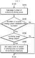
- FIG. 5 is a flowchart showing an operation method of the process S170 shown in FIG. 3 .
- the control module 130 determines whether the number of outputs of the driving pulse (pulse) to be output at the third position control period is greater than a predetermined number S310.
- the control module 130 determines whether the input time-point of the third position calculation interrupt (int3) coincides with the set start time-point of the third position control period S320.
- the control module 130 When it is determined that the input time-point of the third position calculation interrupt (int3) coincides with the start time-point of the third position control period, the control module 130 performs an operation S360 as described later.
- the control module 130 determines whether the input time-point of the third position calculation interrupt (int3) is earlier than the start time-point of the third position control period S330.
- the control module 130 When it is determined based on the result of the operation S330 that the input time-point of the third position calculation interrupt (int3) is earlier than the start time-point of the third position control period, the control module 130 reduces the output rate of the driving pulse (pulse) by an amount corresponding to the difference between the input time-point and the start time-point S340.
- the control module 130 increases the output rate of the driving pulse (pulse) by an amount corresponding to the difference between the input time-point and the start time-point S350.
- control module 130 resets the output rate or period of the driving pulse (pulse) or the number of the correction interrupts (DMA ints) S360.
Landscapes
- Engineering & Computer Science (AREA)
- Physics & Mathematics (AREA)
- General Physics & Mathematics (AREA)
- Automation & Control Theory (AREA)
- Human Computer Interaction (AREA)
- Manufacturing & Machinery (AREA)
- Power Engineering (AREA)
- Programmable Controllers (AREA)
Abstract
Description
- The present disclosure relates to a position control device based on a PLC (programmable logic controller), and, more specifically, to a PLC-based position control device for accurately moving a movable object to a determined target position.
- A PLC (Programmable Logic Controller) is connected to various servo driving devices or stepping motor control driving devices, and performs high precision position control using a driving pulse. The PLC may allow a movable object (workpiece, tool), etc. to be be moved from a current position to a set target position precisely at a set speed.
- It may be difficult to miniaturize a PLC device using a dedicated ASIC that outputs the driving pulse. A manufacturing cost thereof may be increased. Conversely, a PLC device that does not employ the dedicated ASIC has a low precision in a position control.
- In recent years, PLCs capable of performing multi-axis control using a plurality of channels or motors have been developed.
- The present disclosure is to provide a PLC-based position control device for accurately moving a movable object to a determined target position.
- The purposes of the present disclosure are not limited to the above-mentioned purposes. Other purposes and advantages of the present disclosure, as not mentioned above, may be understood from the following descriptions and more clearly understood from the embodiments of the present disclosure. Further, it will be readily appreciated that the objects and advantages of the present disclosure may be realized by features and combinations thereof as disclosed in the claims.
- In one aspect of the present disclosure, there is provided a device for controlling a position based on a programmable logic controller (PLC), the device comprising: a motor driving module configured to drive a motor to move a movable object; an input module configured to input a position command for determining a target position of the movable object; and a control module configured to output a driving pulse for operating the motor driving module based on the position command, wherein the control module includes: a profile creation unit configured for creating the position profile based on the position command when a first position calculation interrupt is generated in a first position control period; a pulse calculation unit configured for calculating a number of outputs of the driving pulse to be output in a second position control period following the first position control period based on the position profile; and a driving controller configured for outputting the driving pulse having the number of outputs calculated by the pulse calculation unit to the motor driving module when a second position calculation interrupt notifying a start time-point of the second position control period is generated.
- In one embodiment, the control module may further include: a first interrupt generation unit configured for generating the first and second position calculation interrupts; and a second interrupt generation unit configured for generating a pulse interrupt for outputting the driving pulse prior to the start time-point of the second position control period.
- In one embodiment, the profile creation unit may be configured for generating the position profile including an output rate of and a number of outputs of the driving pulse to be output in the second position control period, based on the position command.
- In one embodiment, the pulse calculation unit may include a buffer for storing the number of the outputs of the driving pulse.
- In one embodiment, the driving controller may be configured to be activated for outputting of the driving pulse having the number calculated by the pulse calculation unit upon receiving the pulse interrupt, wherein then the second position calculation interrupt is generated, the driving controller is configured to output the driving pulse.
- In one embodiment, the first interrupt generation unit may be configured to: output the driving pulse; and at the same time, generate a third position calculation interrupt such that a number of outputs of a next driving pulse to be output in a third position control period following the second position control period is calculated by the pulse calculation unit.
- In one embodiment, the driving controller may be configured to determine whether a generation time-point of the third position calculation interrupt coincides with a start time-point of the third position control period.
- In one embodiment, the driving controller may be further configured to: upon determination that the generation time-point of the third position calculation interrupt is earlier than the start time-point of the third position control period, reduce an output rate of the next driving pulse to be output at the fourth position control period after the third position control period.
- In one embodiment, the driving controller may be further configured to: upon determination that the generation time-point of the third position calculation interrupt is later than the start time-point of the third position control period, increase an output rate of the next driving pulse to be output at the fourth position control period after the third position control period.
- The PLC-based position control device according to the present disclosure has an advantage in that an error accumulated in each position control period may be reduced by correcting the number and rate of driving pulses based on a set position control period.
- Further, the PLC-based position control device according to the present disclosure sequentially generates position calculation interrupts for multi-axis control according to set position control periods to prevent delay of a driving pulse as generated in a corresponding position control period.
- Further specific effects of the present disclosure as well as the effects as described above will be described in conduction with illustrations of specific details for carrying out the invention.
-
-
FIG. 1 is a control block diagram of a PLC-based position control device according to the present disclosure. -
FIG. 2 is a timing diagram showing a driving pulse output from the PLC-based position control device according to the present disclosure. -
FIG. 3 is a flowchart showing an operation method of the PLC-based position control device according to the present disclosure. -
FIG. 4 is a flowchart showing an operation method of a process S130 shown inFIG. 3 . -
FIG. 5 is a flowchart showing an operation method of a process S170 shown inFIG. 3 . - The above objects, features and advantages will become apparent from the detailed description with reference to the accompanying drawings. Embodiments are described in sufficient detail to enable those skilled in the art in the art to easily practice the technical idea of the present disclosure. Detailed descriptions of well-known functions or configurations may be omitted in order not to unnecessarily obscure the gist of the present disclosure. Hereinafter, embodiments of the present disclosure will be described in detail with reference to the accompanying drawings. Throughout the drawings, like reference numerals refer to like elements.
-
FIG. 1 is a control block diagram of a PLC-based position control device according to the present disclosure. - Referring to
FIG. 1 , a PLC-basedposition control device 100 may include aninput module 110, amotor driving module 120, and acontrol module 130. - In this connection, the
input module 110 may input a position command (a) to determine a target position of a movable object by a user or an operator. - The
motor driving module 120 may actuate a servo motor controlling a plurality of axes to move a movable object to a target position. - In an embodiment, the
motor driving module 120 may actuate a plurality of servo motors (not shown) controlling the plurality of axes based on a driving pulse output from thecontrol module 130. - The
control module 130 may include first and secondinterrupt generation units profile creation unit 135, apulse calculation unit 137, and adriving controller 139. - When a position command (a) is input, the first
interrupt generation unit 131 may generate a first position calculation interrupt (int1) such that a position profile corresponding to the position command (a) is created. - The first
interrupt generation unit 131 may then output the first position calculation interrupt (int1) to theprofile creation unit 135. - After outputting the first position calculation interrupt (int1), the first
interrupt generation unit 131 may generate a position calculation interrupt int according to a position control period based on the position profile (profile) created in theprofile creation unit 135. - When the position command (a) is input and the first position calculation interrupt (int1) output from the first
interrupt generation unit 131 is input in the first position calculation period, theprofile creation unit 135 may create a position profile (profile) corresponding to the position command a. - In this connection, the position profile may include output rate information of the driving pulses and number information of outputs of the driving pulses (pulse).
- That is, the
profile creation unit 135 may generate information on the driving pulse (pulse) based on the position command (a) input from theinput module 110. - The
pulse calculation unit 137 may calculate the number of outputs of driving pulses (pulse) to be output in a second position control period following the first position control period, based on the position profile (profile). Thepulse calculation unit 137 may store the calculated number of outputs of the driving pulses (pulse) in abuffer 138. - In this regard, the second
interrupt generation unit 133 may generate a pulse interrupt (pulse int) for outputting the driving pulse (pulse) and output the pulse interrupt (pulse int) to thedriving controller 139 according to the position profile (profile), in synchronization with the second position control period, and prior to generation of a third position calculation interrupt (int3). - When the pulse interrupt (pulse int) is input from the second
interrupt generation unit 133, thedriving controller 139 is driven for outputting the driving pulse (pulse) calculated by thepulse calculation unit 137. When the second position calculation interrupt (int2) indicating a start time-point of the second position control period is input from the firstinterrupt generation unit 131, thedriving controller 139 may output the driving pulse (pulse int) to themotor driving module 120. - After outputting the second position calculation interrupt (int2), the first
interrupt generation unit 131 may generate a third position calculation interrupt (int3) that signals a start time-point of the third position control period after the second position control period. - In this connection, the
driving controller 139 may determine whether a generation time-point or input time-point of the third position calculation interrupt (int3) coincides with a start time-point of the third position control period. - When the generation time-point of the third position calculation interrupt (int3) is earlier than the start time-point of the third position control period, the
driving controller 139 may reduce an output rate of a next driving pulse to be output at a fourth position control period after the third position control period. - Further, when the generation time-point of the third position calculation interrupt (int3) is later than the start time-point of the third position control period, the
driving controller 139 may increase the output rate of the next driving pulse to be output at the fourth position control period following the third position control period. - The
driving controller 139 compares the generation time-point of the position calculation interrupt (int) with the start time-point of the position control period. Then, thecontroller 139 adjusts the output rate of the driving pulse to be output in the next position control period based on the comparison result. Accordingly, the delay of the start time point of the position control period may be prevented. - Further, the
driving controller 139 varies the start time-point of the position control period of each of the plurality of servomotors at a predetermined time interval. Accordingly, there is an advantage that the delay of the driving pulse supplied to each of the plurality of servomotors may be prevented. -
FIG. 2 is a timing diagram showing the driving pulse output from the PLC-based position control device according to the present disclosure. -
FIG. 2 is a timing diagram showing generation time points of first to fifth position calculation interrupts (intl to int5), pulse interrupts (pulse ints), and correction interrupts (DMA ints), and timing of supplying driving pulses (pulses). - When the position command (a) is input in the first position control period where the driving pulse (pulse) is not output, the
control module 130 creates the position profile (profile), and, at the same time, themodule 130 generates the first position calculation interrupt (int1) to calculate the number of outputs of the driving pulse to be output in the second position control period. - The
control module 130 generates the pulse interrupt (fint) prior to the end time-point of the first position control period. Thus, themodule 130 may output the driving pulse (pulse) in synchronization with the second position control period and before a start time-point of the next second position control period. - In this connection, at the start time-point of the second position control period, the
control module 130 generates the second position calculation interrupt int2 to calculate the number of outputs of the driving pulse (pulse) to be output at the third position control period. - At the end time-point of the second position control period or at the start time-point of the third position control period, the
control module 130 generates the third position calculation interrupt (int3) to calculate the number of outputs of the driving pulse (pulse) to be output at the fourth position control period. - Further, at the end time point of the second position control period or at the start time-point of the third position control period, the
control module 130 generates a correction interrupt (DMA int) to correct the output rate of the driving pulse to be output at the fourth position control period. - The correction interrupt (DMA int) refers to an interrupt for correcting the output rate of the driving pulse (pulse) in order to prevent the delay of the driving pulse to be output in the third position control period.
- When the correction interrupt (DMA int) is generated, the
control module 130 compares the generation time-point of the third position calculation interrupt (int3) with the start time-point of the third position control period, themodule 130 may correct the output rate of the driving pulse (pulse) based on the comparison result. - Thus, the
control module 130 may prevent the delay of the driving pulse (pulse) output between the current position control period and the next position control period. - At the end time-point of the third position control period or at the start time-point of the fourth position control period, the
control module 130 generates a fourth position calculation interrupt (int4) to calculate the number of outputs of the driving pulse (pulse) to be output at a fifth position control period. Thecontrol module 130 may repeatedly perform the above procedure until the end time-point of the position control recorded in the position profile to correct the output rate of the driving pulse (pulse). -
FIG. 3 is a flowchart showing an operation method of a PLC-based position control device according to the present disclosure. - Referring to
FIG. 3 , when the position command (a) is input in the first position control period, thecontrol module 130 of theposition control device 100 may create the position profile (profile) S110. - The
control module 130 may generate the first position calculation interrupt (int1) based on the position profile (profile). Themodule 130 may calculate the number of outputs of the driving pulse (pulse) to be output in the second position control period after the first position control period S120. - The
control module 130 may generate the pulse interrupt (pulse int) for outputting the driving pulse (pulse) at the start time point of the second position control period or the end time-point of the first position control period, that is, in association with the second position control period S130. - Then, when the second position calculation interrupt (int2) indicating the start time-point of the second position control period is generated, the
control module 130 may output the driving pulse (pulse) to themotor driving module 120 at S140. - At the generation time-point of the second position calculation interrupt (int2), that is, the start time point of the second position control period, the
control module 130 may also calculate the number of driving pulses (pulse) to be output at the next third position control period S150. - The
control module 130 may generate the third position calculation interrupt (int3) and the correction interrupt (DMA int) at the start time-point of the third position control period S160. - When the correction interrupt (DMA int) is generated, the
control module 130 may also correct the output rate of the driving pulse (pulse) to be output at the third position control period S170. - The
control module 130 may supply the driving pulse (pulse) having the corrected output rate to themotor driving module 120 in the third position control period. Themodule 130 may repeat the operations S150 to S170 until a time-point at which the position control period ends based on the position profile. - For example, when the position control period ends at the fourth position control period based on the position profile, the
control module 130 may correct, at the start time-point of the third position control period, the driving pulse (pulse) to be output at the next position control period and the output rate of the driving pulse (pulse). -
FIG. 4 is a flowchart showing an operation method of the process S130 shown inFIG. 3 . - Referring to
FIG. 4 , thecontrol module 130 generates the pulse interrupt (pulse int) for the output of the driving pulse (pulse) before the generation of the second position calculation interrupt (int2) S210. - The
control module 130 determines whether the number of outputs of the driving pulse (pulse) is greater than a predetermined number. When the number of outputs of the driving pulse (pulse) is greater than the predetermined number, themodule 130 may determine whether or not the driving pulse is being output. - In this connection, in operation S220, when the number of outputs of the driving pulse (pulse) is smaller than or equal to the predetermined number, or when the driving pulse is being output at operation S230, the
control module 130 ends generation of the pulse interrupt (pulse int). - When it is determined in S230 that the driving pulse is not being output, the
control module 130 may set the output rate or period of the driving pulse (pulse), or the number of the correction interrupts (DMA ints) based on the position profile S240. -
FIG. 5 is a flowchart showing an operation method of the process S170 shown inFIG. 3 . - When the correction interrupt (DMA int) is generated, the
control module 130 determines whether the number of outputs of the driving pulse (pulse) to be output at the third position control period is greater than a predetermined number S310. - The
control module 130 determines whether the input time-point of the third position calculation interrupt (int3) coincides with the set start time-point of the third position control period S320. - When it is determined that the input time-point of the third position calculation interrupt (int3) coincides with the start time-point of the third position control period, the
control module 130 performs an operation S360 as described later. - Further, when the input time-point of the third position calculation interrupt (int3) does not coincide with the start time-point of the third position control period, the
control module 130 determines whether the input time-point of the third position calculation interrupt (int3) is earlier than the start time-point of the third position control period S330. - When it is determined based on the result of the operation S330 that the input time-point of the third position calculation interrupt (int3) is earlier than the start time-point of the third position control period, the
control module 130 reduces the output rate of the driving pulse (pulse) by an amount corresponding to the difference between the input time-point and the start time-point S340. - When it is determined based on the result of the operation S330 that the input time-point of the third position calculation interrupt (int3) is later than the start time-point of the third position control period, the
control module 130 increases the output rate of the driving pulse (pulse) by an amount corresponding to the difference between the input time-point and the start time-point S350. - After the operation S340 and operation S350, the
control module 130 resets the output rate or period of the driving pulse (pulse) or the number of the correction interrupts (DMA ints) S360. - The foregoing disclosure is subject to various substitutions, modifications, and alterations by those skilled in the art to which the present disclosure belongs, without departing from the technical idea of the present disclosure. Therefore, the present disclosure is not limited to the above-described embodiment and the accompanying drawings.
Claims (9)
- A device (100) for controlling a position based on a programmable logic controller (PLC), the device (100) comprising a motor driving module (120) configured to drive a motor to move a movable object, an input module (110) configured to input a position command for determining a target position of the movable object and a control module (130) configured to output a driving pulse for operating the motor driving module (120) based on the position command,
characterized in that the control module (130) includes:a profile creation unit (135) configured for creating the position profile based on the position command when a first position calculation interrupt is generated in a first position control period;a pulse calculation unit (137) configured for calculating a number of outputs of the driving pulse to be output in a second position control period following the first position control period based on the position profile; anda driving controller (139) configured for outputting the driving pulse having the number of outputs calculated by the pulse calculation unit (137) to the motor driving module (120) when a second position calculation interrupt notifying a start time-point of the second position control period is generated. - The device (100) of claim 1, characterized in that the control module (130) further includes:a first interrupt generation unit (131) configured for generating the first and second position calculation interrupts; anda second interrupt generation unit (133) configured for generating a pulse interrupt for outputting the driving pulse prior to the start time-point of the second position control period.
- The device (100) of claim 2, characterized in that the profile creation unit (135) is configured for generating the position profile including an output rate of and a number of outputs of the driving pulse to be output in the second position control period, based on the position command.
- The device (100) of claim 2, characterized in that the pulse calculation unit (137) includes a buffer (138) for storing the number of the outputs of the driving pulse.
- The device (100) of claim 2, characterized in that the driving controller (139) is configured to be activated for outputting of the driving pulse having the number calculated by the pulse calculation unit (137) upon receiving the pulse interrupt, and
characterized in that then the second position calculation interrupt is generated, the driving controller (139) is configured to output the driving pulse. - The device (100) of claim 2, characterized in that the first interrupt generation unit (131) is configured to:output the driving pulse; andat the same time, generate a third position calculation interrupt such that a number of outputs of a next driving pulse to be output in a third position control period following the second position control period is calculated by the pulse calculation unit (137).
- The device (100) of claim 6, characterized in that the driving controller (139) is configured to determine whether a generation time-point of the third position calculation interrupt coincides with a start time-point of the third position control period.
- The device (100) of claim 7, characterized in that the driving controller (139) is further configured:upon determination that the generation time-point of the third position calculation interrupt is earlier than the start time-point of the third position control period,to reduce an output rate of the next driving pulse to be output at the fourth position control period after the third position control period.
- The device (100) of claim 7, characterized in that the driving controller (139) is further configured:upon determination that the generation time-point of the third position calculation interrupt is later than the start time-point of the third position control period,to increase an output rate of the next driving pulse to be output at the fourth position control period after the third position control period.
Applications Claiming Priority (1)
| Application Number | Priority Date | Filing Date | Title |
|---|---|---|---|
| KR1020180047898A KR102115310B1 (en) | 2018-04-25 | 2018-04-25 | Position control apparatus based on programmable logic controller |
Publications (2)
| Publication Number | Publication Date |
|---|---|
| EP3561619A1 true EP3561619A1 (en) | 2019-10-30 |
| EP3561619B1 EP3561619B1 (en) | 2021-07-21 |
Family
ID=64959148
Family Applications (1)
| Application Number | Title | Priority Date | Filing Date |
|---|---|---|---|
| EP18214256.2A Active EP3561619B1 (en) | 2018-04-25 | 2018-12-19 | Position control device based on programmable logic controller |
Country Status (6)
| Country | Link |
|---|---|
| US (1) | US10528022B2 (en) |
| EP (1) | EP3561619B1 (en) |
| JP (1) | JP6833799B2 (en) |
| KR (1) | KR102115310B1 (en) |
| CN (1) | CN110398933B (en) |
| ES (1) | ES2890530T3 (en) |
Citations (3)
| Publication number | Priority date | Publication date | Assignee | Title |
|---|---|---|---|---|
| EP0393650A2 (en) * | 1989-04-21 | 1990-10-24 | Vickers Incorporated | High resolution pulse width modulation |
| US20140149612A1 (en) * | 2012-11-26 | 2014-05-29 | Renesas Electronics Corporation | Microcomputer |
| US8890457B2 (en) * | 2008-09-19 | 2014-11-18 | Hewlett-Packard Development Company, L.P. | Systems and methods for controlling motors |
Family Cites Families (9)
| Publication number | Priority date | Publication date | Assignee | Title |
|---|---|---|---|---|
| US6865425B2 (en) * | 2002-01-07 | 2005-03-08 | Siemens Energy & Automation, Inc. | State machine for a pulse output function |
| TWI220700B (en) | 2003-08-20 | 2004-09-01 | Delta Electronics Inc | Programmable logic controller with an auxiliary processing unit |
| KR100777928B1 (en) | 2006-01-27 | 2007-11-21 | 엘에스산전 주식회사 | Speed synchronization method using PI |
| KR100994879B1 (en) * | 2008-12-03 | 2010-11-16 | 엘에스산전 주식회사 | PLC positioning system |
| KR101417197B1 (en) * | 2010-11-30 | 2014-07-08 | 엘에스산전 주식회사 | Apparatus and method for positioning in Programmable Logic Controller, and PLC system using thereof |
| CN102097973B (en) * | 2011-02-15 | 2013-01-09 | 南京航空航天大学 | Ultrasonic motor driving controller based on embedded chip |
| KR20150074392A (en) * | 2013-12-24 | 2015-07-02 | 엘에스산전 주식회사 | Method for setting control period of the positioning system |
| KR102079499B1 (en) * | 2015-10-20 | 2020-02-21 | 엘에스산전 주식회사 | A method of independent control period allocation of axis in the PLC positioning system |
| JP6805732B2 (en) * | 2016-10-31 | 2020-12-23 | オムロン株式会社 | Control system, its control method and recording medium |
-
2018
- 2018-04-25 KR KR1020180047898A patent/KR102115310B1/en active Active
- 2018-12-18 US US16/223,714 patent/US10528022B2/en active Active
- 2018-12-19 ES ES18214256T patent/ES2890530T3/en active Active
- 2018-12-19 EP EP18214256.2A patent/EP3561619B1/en active Active
- 2018-12-20 JP JP2018238546A patent/JP6833799B2/en active Active
-
2019
- 2019-01-23 CN CN201910063537.5A patent/CN110398933B/en active Active
Patent Citations (3)
| Publication number | Priority date | Publication date | Assignee | Title |
|---|---|---|---|---|
| EP0393650A2 (en) * | 1989-04-21 | 1990-10-24 | Vickers Incorporated | High resolution pulse width modulation |
| US8890457B2 (en) * | 2008-09-19 | 2014-11-18 | Hewlett-Packard Development Company, L.P. | Systems and methods for controlling motors |
| US20140149612A1 (en) * | 2012-11-26 | 2014-05-29 | Renesas Electronics Corporation | Microcomputer |
Also Published As
| Publication number | Publication date |
|---|---|
| CN110398933B (en) | 2022-06-21 |
| US10528022B2 (en) | 2020-01-07 |
| JP6833799B2 (en) | 2021-02-24 |
| ES2890530T3 (en) | 2022-01-20 |
| JP2019192208A (en) | 2019-10-31 |
| CN110398933A (en) | 2019-11-01 |
| EP3561619B1 (en) | 2021-07-21 |
| KR102115310B1 (en) | 2020-05-26 |
| US20190332080A1 (en) | 2019-10-31 |
| KR20190123948A (en) | 2019-11-04 |
Similar Documents
| Publication | Publication Date | Title |
|---|---|---|
| EP1967924A1 (en) | Apparatus for synchronously controlling a plurality of servomotors | |
| US7167772B2 (en) | Machining time calculating apparatus | |
| JP2013011937A (en) | Synchronous control device, synchronous control method, synchronous control program, and computer readable recording medium on which synchronous control program is recorded | |
| JP2017102617A (en) | Correction apparatus, correction apparatus control method, information processing program, and recording medium | |
| KR20170045940A (en) | Multi-Servo control system | |
| JP2009279608A (en) | System including robot and press, system including a plurality of robots, and controller for robot used in the same system | |
| CN112865750A (en) | Numerical control system multiplying power change smooth control method and device based on FIR filter | |
| JP3795854B2 (en) | Laser processing equipment | |
| US10569358B2 (en) | Laser processing system capable of adjusting timing to switch output command | |
| US20170108847A1 (en) | Numerical controller performing positioning for avoiding interference with workpiece | |
| CN109960221A (en) | Numerical control device | |
| US10915093B2 (en) | Numerical controller | |
| US10528022B2 (en) | Position control device based on programmable logic controller | |
| US9880525B2 (en) | Positioning apparatus and PLC system using same | |
| EP2733562A1 (en) | Trigger emission device | |
| US9417623B2 (en) | Numerical control device with servo-output delay unit | |
| JP2007025759A (en) | Electric motor drive device, position command device, and positioning device | |
| EP4184265A1 (en) | System and method for managing automation systems with synchronous elements | |
| US20210018891A1 (en) | Controller for machine tool and control system | |
| US20230159279A1 (en) | System and method for managing automation systems with jerk compensation | |
| JP4436809B2 (en) | Laser processing system | |
| CN111203653A (en) | Self-adaptive control device for adjusting position of laser cutting head and control method thereof | |
| JP7398947B2 (en) | motor control device | |
| US10514674B2 (en) | Numerical controller | |
| CN103760828A (en) | Speed planning method of chip mounter Y-axis servo motor |
Legal Events
| Date | Code | Title | Description |
|---|---|---|---|
| PUAI | Public reference made under article 153(3) epc to a published international application that has entered the european phase |
Free format text: ORIGINAL CODE: 0009012 |
|
| STAA | Information on the status of an ep patent application or granted ep patent |
Free format text: STATUS: THE APPLICATION HAS BEEN PUBLISHED |
|
| AK | Designated contracting states |
Kind code of ref document: A1 Designated state(s): AL AT BE BG CH CY CZ DE DK EE ES FI FR GB GR HR HU IE IS IT LI LT LU LV MC MK MT NL NO PL PT RO RS SE SI SK SM TR |
|
| AX | Request for extension of the european patent |
Extension state: BA ME |
|
| STAA | Information on the status of an ep patent application or granted ep patent |
Free format text: STATUS: REQUEST FOR EXAMINATION WAS MADE |
|
| 17P | Request for examination filed |
Effective date: 20200423 |
|
| RBV | Designated contracting states (corrected) |
Designated state(s): AL AT BE BG CH CY CZ DE DK EE ES FI FR GB GR HR HU IE IS IT LI LT LU LV MC MK MT NL NO PL PT RO RS SE SI SK SM TR |
|
| GRAP | Despatch of communication of intention to grant a patent |
Free format text: ORIGINAL CODE: EPIDOSNIGR1 |
|
| STAA | Information on the status of an ep patent application or granted ep patent |
Free format text: STATUS: GRANT OF PATENT IS INTENDED |
|
| INTG | Intention to grant announced |
Effective date: 20210329 |
|
| GRAS | Grant fee paid |
Free format text: ORIGINAL CODE: EPIDOSNIGR3 |
|
| GRAA | (expected) grant |
Free format text: ORIGINAL CODE: 0009210 |
|
| STAA | Information on the status of an ep patent application or granted ep patent |
Free format text: STATUS: THE PATENT HAS BEEN GRANTED |
|
| AK | Designated contracting states |
Kind code of ref document: B1 Designated state(s): AL AT BE BG CH CY CZ DE DK EE ES FI FR GB GR HR HU IE IS IT LI LT LU LV MC MK MT NL NO PL PT RO RS SE SI SK SM TR |
|
| REG | Reference to a national code |
Ref country code: GB Ref legal event code: FG4D |
|
| REG | Reference to a national code |
Ref country code: CH Ref legal event code: EP |
|
| REG | Reference to a national code |
Ref country code: DE Ref legal event code: R096 Ref document number: 602018020390 Country of ref document: DE |
|
| REG | Reference to a national code |
Ref country code: AT Ref legal event code: REF Ref document number: 1413149 Country of ref document: AT Kind code of ref document: T Effective date: 20210815 |
|
| REG | Reference to a national code |
Ref country code: IE Ref legal event code: FG4D |
|
| REG | Reference to a national code |
Ref country code: LT Ref legal event code: MG9D |
|
| REG | Reference to a national code |
Ref country code: NL Ref legal event code: MP Effective date: 20210721 |
|
| REG | Reference to a national code |
Ref country code: AT Ref legal event code: MK05 Ref document number: 1413149 Country of ref document: AT Kind code of ref document: T Effective date: 20210721 |
|
| REG | Reference to a national code |
Ref country code: ES Ref legal event code: FG2A Ref document number: 2890530 Country of ref document: ES Kind code of ref document: T3 Effective date: 20220120 |
|
| PG25 | Lapsed in a contracting state [announced via postgrant information from national office to epo] |
Ref country code: RS Free format text: LAPSE BECAUSE OF FAILURE TO SUBMIT A TRANSLATION OF THE DESCRIPTION OR TO PAY THE FEE WITHIN THE PRESCRIBED TIME-LIMIT Effective date: 20210721 Ref country code: SE Free format text: LAPSE BECAUSE OF FAILURE TO SUBMIT A TRANSLATION OF THE DESCRIPTION OR TO PAY THE FEE WITHIN THE PRESCRIBED TIME-LIMIT Effective date: 20210721 Ref country code: HR Free format text: LAPSE BECAUSE OF FAILURE TO SUBMIT A TRANSLATION OF THE DESCRIPTION OR TO PAY THE FEE WITHIN THE PRESCRIBED TIME-LIMIT Effective date: 20210721 Ref country code: FI Free format text: LAPSE BECAUSE OF FAILURE TO SUBMIT A TRANSLATION OF THE DESCRIPTION OR TO PAY THE FEE WITHIN THE PRESCRIBED TIME-LIMIT Effective date: 20210721 Ref country code: LT Free format text: LAPSE BECAUSE OF FAILURE TO SUBMIT A TRANSLATION OF THE DESCRIPTION OR TO PAY THE FEE WITHIN THE PRESCRIBED TIME-LIMIT Effective date: 20210721 Ref country code: BG Free format text: LAPSE BECAUSE OF FAILURE TO SUBMIT A TRANSLATION OF THE DESCRIPTION OR TO PAY THE FEE WITHIN THE PRESCRIBED TIME-LIMIT Effective date: 20211021 Ref country code: AT Free format text: LAPSE BECAUSE OF FAILURE TO SUBMIT A TRANSLATION OF THE DESCRIPTION OR TO PAY THE FEE WITHIN THE PRESCRIBED TIME-LIMIT Effective date: 20210721 Ref country code: NL Free format text: LAPSE BECAUSE OF FAILURE TO SUBMIT A TRANSLATION OF THE DESCRIPTION OR TO PAY THE FEE WITHIN THE PRESCRIBED TIME-LIMIT Effective date: 20210721 Ref country code: PT Free format text: LAPSE BECAUSE OF FAILURE TO SUBMIT A TRANSLATION OF THE DESCRIPTION OR TO PAY THE FEE WITHIN THE PRESCRIBED TIME-LIMIT Effective date: 20211122 Ref country code: NO Free format text: LAPSE BECAUSE OF FAILURE TO SUBMIT A TRANSLATION OF THE DESCRIPTION OR TO PAY THE FEE WITHIN THE PRESCRIBED TIME-LIMIT Effective date: 20211021 |
|
| PG25 | Lapsed in a contracting state [announced via postgrant information from national office to epo] |
Ref country code: PL Free format text: LAPSE BECAUSE OF FAILURE TO SUBMIT A TRANSLATION OF THE DESCRIPTION OR TO PAY THE FEE WITHIN THE PRESCRIBED TIME-LIMIT Effective date: 20210721 Ref country code: LV Free format text: LAPSE BECAUSE OF FAILURE TO SUBMIT A TRANSLATION OF THE DESCRIPTION OR TO PAY THE FEE WITHIN THE PRESCRIBED TIME-LIMIT Effective date: 20210721 Ref country code: GR Free format text: LAPSE BECAUSE OF FAILURE TO SUBMIT A TRANSLATION OF THE DESCRIPTION OR TO PAY THE FEE WITHIN THE PRESCRIBED TIME-LIMIT Effective date: 20211022 |
|
| REG | Reference to a national code |
Ref country code: DE Ref legal event code: R097 Ref document number: 602018020390 Country of ref document: DE |
|
| PG25 | Lapsed in a contracting state [announced via postgrant information from national office to epo] |
Ref country code: DK Free format text: LAPSE BECAUSE OF FAILURE TO SUBMIT A TRANSLATION OF THE DESCRIPTION OR TO PAY THE FEE WITHIN THE PRESCRIBED TIME-LIMIT Effective date: 20210721 |
|
| PLBE | No opposition filed within time limit |
Free format text: ORIGINAL CODE: 0009261 |
|
| STAA | Information on the status of an ep patent application or granted ep patent |
Free format text: STATUS: NO OPPOSITION FILED WITHIN TIME LIMIT |
|
| PG25 | Lapsed in a contracting state [announced via postgrant information from national office to epo] |
Ref country code: SM Free format text: LAPSE BECAUSE OF FAILURE TO SUBMIT A TRANSLATION OF THE DESCRIPTION OR TO PAY THE FEE WITHIN THE PRESCRIBED TIME-LIMIT Effective date: 20210721 Ref country code: SK Free format text: LAPSE BECAUSE OF FAILURE TO SUBMIT A TRANSLATION OF THE DESCRIPTION OR TO PAY THE FEE WITHIN THE PRESCRIBED TIME-LIMIT Effective date: 20210721 Ref country code: RO Free format text: LAPSE BECAUSE OF FAILURE TO SUBMIT A TRANSLATION OF THE DESCRIPTION OR TO PAY THE FEE WITHIN THE PRESCRIBED TIME-LIMIT Effective date: 20210721 Ref country code: EE Free format text: LAPSE BECAUSE OF FAILURE TO SUBMIT A TRANSLATION OF THE DESCRIPTION OR TO PAY THE FEE WITHIN THE PRESCRIBED TIME-LIMIT Effective date: 20210721 Ref country code: CZ Free format text: LAPSE BECAUSE OF FAILURE TO SUBMIT A TRANSLATION OF THE DESCRIPTION OR TO PAY THE FEE WITHIN THE PRESCRIBED TIME-LIMIT Effective date: 20210721 Ref country code: AL Free format text: LAPSE BECAUSE OF FAILURE TO SUBMIT A TRANSLATION OF THE DESCRIPTION OR TO PAY THE FEE WITHIN THE PRESCRIBED TIME-LIMIT Effective date: 20210721 |
|
| 26N | No opposition filed |
Effective date: 20220422 |
|
| PG25 | Lapsed in a contracting state [announced via postgrant information from national office to epo] |
Ref country code: MC Free format text: LAPSE BECAUSE OF FAILURE TO SUBMIT A TRANSLATION OF THE DESCRIPTION OR TO PAY THE FEE WITHIN THE PRESCRIBED TIME-LIMIT Effective date: 20210721 |
|
| REG | Reference to a national code |
Ref country code: CH Ref legal event code: PL |
|
| REG | Reference to a national code |
Ref country code: BE Ref legal event code: MM Effective date: 20211231 |
|
| PG25 | Lapsed in a contracting state [announced via postgrant information from national office to epo] |
Ref country code: LU Free format text: LAPSE BECAUSE OF NON-PAYMENT OF DUE FEES Effective date: 20211219 Ref country code: IE Free format text: LAPSE BECAUSE OF NON-PAYMENT OF DUE FEES Effective date: 20211219 |
|
| PG25 | Lapsed in a contracting state [announced via postgrant information from national office to epo] |
Ref country code: BE Free format text: LAPSE BECAUSE OF NON-PAYMENT OF DUE FEES Effective date: 20211231 |
|
| PG25 | Lapsed in a contracting state [announced via postgrant information from national office to epo] |
Ref country code: LI Free format text: LAPSE BECAUSE OF NON-PAYMENT OF DUE FEES Effective date: 20211231 Ref country code: CH Free format text: LAPSE BECAUSE OF NON-PAYMENT OF DUE FEES Effective date: 20211231 |
|
| PG25 | Lapsed in a contracting state [announced via postgrant information from national office to epo] |
Ref country code: CY Free format text: LAPSE BECAUSE OF FAILURE TO SUBMIT A TRANSLATION OF THE DESCRIPTION OR TO PAY THE FEE WITHIN THE PRESCRIBED TIME-LIMIT Effective date: 20210721 |
|
| PG25 | Lapsed in a contracting state [announced via postgrant information from national office to epo] |
Ref country code: HU Free format text: LAPSE BECAUSE OF FAILURE TO SUBMIT A TRANSLATION OF THE DESCRIPTION OR TO PAY THE FEE WITHIN THE PRESCRIBED TIME-LIMIT; INVALID AB INITIO Effective date: 20181219 |
|
| P01 | Opt-out of the competence of the unified patent court (upc) registered |
Effective date: 20230625 |
|
| PG25 | Lapsed in a contracting state [announced via postgrant information from national office to epo] |
Ref country code: MK Free format text: LAPSE BECAUSE OF FAILURE TO SUBMIT A TRANSLATION OF THE DESCRIPTION OR TO PAY THE FEE WITHIN THE PRESCRIBED TIME-LIMIT Effective date: 20210721 |
|
| PG25 | Lapsed in a contracting state [announced via postgrant information from national office to epo] |
Ref country code: TR Free format text: LAPSE BECAUSE OF FAILURE TO SUBMIT A TRANSLATION OF THE DESCRIPTION OR TO PAY THE FEE WITHIN THE PRESCRIBED TIME-LIMIT Effective date: 20210721 |
|
| PG25 | Lapsed in a contracting state [announced via postgrant information from national office to epo] |
Ref country code: MT Free format text: LAPSE BECAUSE OF FAILURE TO SUBMIT A TRANSLATION OF THE DESCRIPTION OR TO PAY THE FEE WITHIN THE PRESCRIBED TIME-LIMIT Effective date: 20210721 |
|
| PGFP | Annual fee paid to national office [announced via postgrant information from national office to epo] |
Ref country code: IT Payment date: 20250909 Year of fee payment: 8 |
|
| PGFP | Annual fee paid to national office [announced via postgrant information from national office to epo] |
Ref country code: FR Payment date: 20250909 Year of fee payment: 8 |
|
| PGFP | Annual fee paid to national office [announced via postgrant information from national office to epo] |
Ref country code: DE Payment date: 20250908 Year of fee payment: 8 |
|
| PGFP | Annual fee paid to national office [announced via postgrant information from national office to epo] |
Ref country code: GB Payment date: 20251001 Year of fee payment: 8 |
|
| PGFP | Annual fee paid to national office [announced via postgrant information from national office to epo] |
Ref country code: ES Payment date: 20260122 Year of fee payment: 8 |