EP3561592B1 - Lens bracket for security camera and security camera having the same - Google Patents
Lens bracket for security camera and security camera having the same Download PDFInfo
- Publication number
- EP3561592B1 EP3561592B1 EP18212309.1A EP18212309A EP3561592B1 EP 3561592 B1 EP3561592 B1 EP 3561592B1 EP 18212309 A EP18212309 A EP 18212309A EP 3561592 B1 EP3561592 B1 EP 3561592B1
- Authority
- EP
- European Patent Office
- Prior art keywords
- lens
- rail
- lens assembly
- bracket
- protrusion
- Prior art date
- Legal status (The legal status is an assumption and is not a legal conclusion. Google has not performed a legal analysis and makes no representation as to the accuracy of the status listed.)
- Active
Links
Images




Classifications
-
- H—ELECTRICITY
- H04—ELECTRIC COMMUNICATION TECHNIQUE
- H04N—PICTORIAL COMMUNICATION, e.g. TELEVISION
- H04N7/00—Television systems
- H04N7/18—Closed-circuit television [CCTV] systems, i.e. systems in which the video signal is not broadcast
-
- G—PHYSICS
- G03—PHOTOGRAPHY; CINEMATOGRAPHY; ANALOGOUS TECHNIQUES USING WAVES OTHER THAN OPTICAL WAVES; ELECTROGRAPHY; HOLOGRAPHY
- G03B—APPARATUS OR ARRANGEMENTS FOR TAKING PHOTOGRAPHS OR FOR PROJECTING OR VIEWING THEM; APPARATUS OR ARRANGEMENTS EMPLOYING ANALOGOUS TECHNIQUES USING WAVES OTHER THAN OPTICAL WAVES; ACCESSORIES THEREFOR
- G03B17/00—Details of cameras or camera bodies; Accessories therefor
- G03B17/56—Accessories
- G03B17/561—Support related camera accessories
-
- G—PHYSICS
- G02—OPTICS
- G02B—OPTICAL ELEMENTS, SYSTEMS OR APPARATUS
- G02B7/00—Mountings, adjusting means, or light-tight connections, for optical elements
- G02B7/02—Mountings, adjusting means, or light-tight connections, for optical elements for lenses
-
- H—ELECTRICITY
- H04—ELECTRIC COMMUNICATION TECHNIQUE
- H04N—PICTORIAL COMMUNICATION, e.g. TELEVISION
- H04N23/00—Cameras or camera modules comprising electronic image sensors; Control thereof
- H04N23/50—Constructional details
- H04N23/51—Housings
-
- H—ELECTRICITY
- H04—ELECTRIC COMMUNICATION TECHNIQUE
- H04N—PICTORIAL COMMUNICATION, e.g. TELEVISION
- H04N23/00—Cameras or camera modules comprising electronic image sensors; Control thereof
- H04N23/50—Constructional details
- H04N23/55—Optical parts specially adapted for electronic image sensors; Mounting thereof
Definitions
- Exemplary embodiments/implementations of the invention relate generally to an apparatus and, more specifically, to a lens bracket for a security camera and a security camera having the same.
- General security cameras may photograph events occurring outside by using cameras. Recently, a security camera may have a plurality of lens assemblies to capture an image of an event occurring in various directions.
- Various structures may be employed to arrange a plurality of lens assemblies at various angles.
- a plurality of lens assemblies are generally fixed at particular positions in a housing using screws or bolts. In this case, when at least one of the lens assemblies is removed, positions of the other lens assemblies may not be changed, and thus a wide blind spot of a security camera may be generated.
- the lens assemblies may be fixed at various positions.
- a housing needs to be changed to arrange each of the lens assemblies that are fixed at another position in the housing.
- the lens assemblies arranged at particular positions may not be able to be installed at other positions.
- U.S. Patent Publication No. 2017-0299949 (Title of the Invention: Omnidirectional User Configurable Multi-Camera Housing, Applicant: Arecont Vision, LLC) discloses such a security camera.
- US 2015/0090849 A1 and US 2013/160345 A1 disclose a lens bracket including a moving portion and a hooking portion.
- Devices constructed according to exemplary implementations of the invention include a lens bracket for a security camera and a security camera having the same.
- a lens bracket is provided as defined in claim 1.
- the hooking portion may include a coupling connection portion protruding from the moving portion toward the rail, at least a part of the coupling connection portion being bent surrounding a side surface of the rail,; and a position fixing protrusion protruding from the coupling connection portion toward the rail protrusion of the rail.
- the coupling protrusion may protrude from the moving portion toward the rail, and at least a part of the coupling protrusion may be bent surrounding the rail.
- the moving portion may include a moving body portion, and a handle portion provided separately from the moving body portion, the hooking portion being connected to the handle portion.
- the lens bracket may further include a contact protrusion that protrudes from a lower surface of the moving portion toward the rail.
- a security camera include a lens assembly; a lens bracket into which a protruding portion of the lens assembly is rotatably inserted; and a stopper provided on the lens assembly and rotating in contact with the lens bracket during rotation of the lens assembly, wherein the stopper determines an angle range in which the protruding portion of the lens assembly is drawn from an open portion of the lens bracket and thus the lens assembly and the lens bracket are separated from each other.
- a security camera include: a lens assembly; the lens bracket as defined above into which a protruding portion of the lens assembly is rotatably inserted and to which the lens assembly is detachably connected; and a lens assembly accommodation portion spaced apart from the lens bracket, into which the lens assembly separated from the lens bracket is inserted and fixed.
- the lens assembly may include a stopper that determines an angle range in which the protruding portion of the lens assembly is drawn from an open portion of the lens bracket and thus the lens assembly and the lens bracket are separated from each other.
- the security camera may further include a rotation prevention portion that is provided on at least one of the lens bracket and the stopper.
- a part of the lens bracket that the stopper contacts may be curved.
- the lens assembly accommodation portion may include a snap fit into which the stopper is inserted and fixed.
- the lens assembly accommodation portion may include a rotation axis insertion groove into which a rotation axis of the lens assembly is inserted.
- the security camera may further comprise a rail detachably connected to the moving portion of the lens bracket.
- the rail may be annular in shape.
- the rail may include a rail protrusion protruding from an outer surface of the rail, the coupling protrusion of the lens bracket may be connected to an inner surface of the rail and the hooking portion may be configured to contact the rail protrusion of the rail.
- the inner surface is a surface that is closest to the lens assembly accommodation portion and the outer surface is a surface that is farthest from the lens assembly accommodation portion.
- the position fixing protrusion of the lens bracket may protrude from the coupling connection portion of the lens bracket toward the rail protrusion of the rail.
- the lens assembly may include a plurality of lens assemblies and the lens bracket includes a plurality of lens brackets, a circular rail is provided on which the plurality of lens brackets independently move, one of the plurality of lens assemblies is provided on the lens assembly accommodation portion located at a center of the rail, and other lens assemblies of the plurality of lens assemblies are provided on the plurality of lens brackets spaced apart from one another.
- the illustrated exemplary embodiments are to be understood as providing exemplary features of varying detail of some ways in which the inventive concepts may be implemented in practice. Therefore, unless otherwise specified, the features, components, modules, layers, films, panels, regions, and/or aspects, etc. (hereinafter individually or collectively referred to as "elements"), of the various embodiments may be otherwise combined, separated, interchanged, and/or rearranged without departing from the inventive concepts.
- the term “connected” may refer to physical, electrical, and/or fluid connection, with or without intervening elements.
- the D1-axis, the D2-axis, and the D3-axis are not limited to three axes of a rectangular coordinate system, such as the x, y, and z - axes, and may be interpreted in a broader sense.
- the D1-axis, the D2-axis, and the D3-axis may be perpendicular to one another, or may represent different directions that are not perpendicular to one another.
- "at least one of X, Y, and Z" and "at least one selected from the group consisting of X, Y, and Z” may be construed as X only, Y only, Z only, or any combination of two or more of X, Y, and Z, such as, for instance, XYZ, XYY, YZ, and ZZ.
- the term "and/or" includes any and all combinations of one or more of the associated listed items.
- Spatially relative terms such as “beneath,” “below,” “under,” “lower,” “above,” “upper,” “over,” “higher,” “side” (e.g., as in “sidewall”), and the like, may be used herein for descriptive purposes, and, thereby, to describe one elements relationship to another element(s) as illustrated in the drawings.
- Spatially relative terms are intended to encompass different orientations of an apparatus in use, operation, and/or manufacture in addition to the orientation depicted in the drawings. For example, if the apparatus in the drawings is turned over, elements described as “below” or “beneath” other elements or features would then be oriented “above” the other elements or features.
- the exemplary term “below” can encompass both an orientation of above and below.
- the apparatus may be otherwise oriented (e.g., rotated 90 degrees or at other orientations), and, as such, the spatially relative descriptors used herein interpreted accordingly.
- exemplary embodiments are described herein with reference to sectional and/or exploded illustrations that are schematic illustrations of idealized exemplary embodiments and/or intermediate structures. As such, variations from the shapes of the illustrations as a result, for example, of manufacturing techniques and/or tolerances, are to be expected. Thus, exemplary embodiments disclosed herein should not necessarily be construed as limited to the particular illustrated shapes of regions, but are to include deviations in shapes that result from, for instance, manufacturing. In this manner, regions illustrated in the drawings may be schematic in nature and the shapes of these regions may not reflect actual shapes of regions of a device and, as such, are not necessarily intended to be limiting.
- FIG. 1 is a perspective view of a security camera 100 according to an exemplary embodiment.
- FIG. 2 is a perspective view of a part of the security camera 100 of FIG. 1 .
- the security camera 100 may include a base housing 111, a fixed housing 112, a cover housing 113, and a cover 130.
- the security camera 100 further includes a lens bracket 120 and a lens assembly 140.
- the lens bracket 120 may be arranged on the base housing 111. Furthermore, the base housing 111 may be fixed on the fixed housing 112. In this state, the base housing 111 may include a rail 111a on which the lens bracket 120 is arranged, a base housing body portion 111b on which the rail 111a is arranged, and a lens assembly accommodation portion 111c arranged at a center of the base housing body portion 111b.
- the rail 111a may have an annular shape. Furthermore, a lower surface of the rail 111a may be formed uneven.
- the rail 111a may include a rail protrusion 111a-1 protruding from the lower surface thereof.
- the rail protrusion 111a-1 may include a plurality of rail protrusions, and the rail protrusions 111a-1 may be arranged on the lower surface of the rail 111a around the outer periphery of the rail 111a.
- Each of the rail protrusions 111a-1 may be arranged on the lower surface of the rail 111a such that a lengthwise direction of each of the rail protrusions 111a-1 directs to the center of the rail 111a.
- the base housing body portion 111b may be arranged on the lower surface of the rail 111a. In this state, the rail 111a may be spaced apart from an upper surface of the base housing body portion 111b.
- the base housing body portion 111b may be provided with a first groove 111b-1 for inserting or removing when the lens bracket 120 is coupled to the rail 111a or separated from the rail 111a.
- the first groove 111b-1 may be indented from an outer surface of the base housing body portion 111b toward a center portion of the base housing body portion 111b.
- the lens assembly accommodation portion 111c may be located at the center of the rail 111a and in which one of a plurality of the lens assemblies 140 may be arranged. In this case, the lens assembly accommodation portion 111c may be coupled to the lens assembly 140 in various forms of inserting the lens assembly 140 therein or fixing the lens assembly 140 thereto. Furthermore, the lens assembly accommodation portion 111c may be formed integrally with the base housing body portion 111b, or separately from the base housing body portion 111b and coupled to the base housing body portion 111b. When the base housing body portion 111b and the lens assembly accommodation portion 111c are separately coupled to each other, the base housing body portion 111b and the lens assembly accommodation portion 111c may be coupled by various methods.
- the base housing body portion 111b and the lens assembly accommodation portion 111c may be connected to each other using various members such as screws or bolts.
- a protrusion such as a hook is formed on one of the base housing body portion 111b and the lens assembly accommodation portion 111c and a recess for accommodating the protrusion is formed in the other one of the base housing body portion 111b and the lens assembly accommodation portion 111c, and then as the protrusion is inserted into the recess, the base housing body portion 111b and the lens assembly accommodation portion 111c may be coupled to each other.
- a case in which the base housing body portion 111b and the lens assembly accommodation portion 111c are separately formed and coupled to each other is mainly described in detail.
- the base housing 111 may be coupled to the fixed housing 112.
- the fixed housing 112 may be fixed to an outer wall of a building.
- the fixed housing 112 may be fixed using bolts or screws.
- the base housing 111 and the fixed housing 112 may be coupled by various methods.
- the base housing 111 and the fixed housing 112 may be coupled to each other using bolts, screws, or pins.
- the base housing 111 may be pivotably coupled to the fixed housing 112 and may be connected to the fixed housing 112 using a hook.
- the cover housing 113 is coupled to at least one of the fixed housing 112 and the base housing 111 and may fix the cover 130. In this state, the cover housing 113 may shield a part of the cover 130 and may shield the fixed housing 112 and the base housing 111.
- the lens bracket 120 may be detachably coupled to the rail 111a.
- the lens bracket 120 may be coupled to the rail 111a to be movable along the rail 111a.
- the cover 130 may be coupled to the base housing 111 and may shield parts arranged between the cover 130 and the base housing 111 from the outside.
- the cover 130 may include a cover body portion 131 and a force applying portion 132.
- the cover body portion 131 may have a dome shape with a partially flat portion.
- a side portion of the base housing 111 may be formed to be curved and one surface of the cover body portion 131 facing the ground may be formed to be flat.
- the cover body portion 131 may be formed of a transparent material such as acryl, glass, or plastic.
- a sealing member may be provided between the cover body portion 131 and the base housing 111 to prevent intrusion of moisture from the outside.
- the cover body portion 131 and the base housing 111 may be coupled to each other by various methods. In an exemplary embodiment, the cover body portion 131 and the base housing 111 may be fixed using a separate clamp.
- a protrusion may be formed on one of the cover body portion 131 and the base housing 111, and a groove or hole for accommodating the protrusion may be formed in the other one of the cover body portion 131 and the base housing 111. Accordingly, as the protrusion is inserted into the groove or hole, the cover body portion 131 and the base housing 111 may be coupled to each other.
- the force applying portion 132 may protrude from the cover body portion 131 toward the lens bracket 120.
- the force applying portion 132 may be integrally formed with the cover body portion 131, or separately from the cover body portion 131 and coupled to the cover body portion 131.
- the force applying portion 132 may be formed of the same material as the cover body portion 131.
- the force applying portion 132 may be coupled to the cover body portion 131 using a separate adhesive member.
- the force applying portion 132 may be formed of an elastic material such as rubber, silicon, or plastic.
- the lens assembly 140 may be coupled to at least one of the lens assembly accommodation portion 111c and the lens bracket 120.
- the lens assembly 140 may include a plurality of lens assemblies, in which one of the lens assemblies 140 may be coupled to the lens assembly accommodation portion 111c and the others may be coupled to the lens bracket 120.
- the lens bracket 120 may include a plurality of lens brackets corresponding to the number of lens assemblies 140.
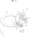
- FIG. 3 is a perspective view of the lens bracket 120 and the rail 111a illustrated in FIG. 2 .
- FIG. 4 is a partial perspective view showing lower surfaces of the lens bracket 120 and the rail 111a of FIG. 3 .
- FIG. 5 is a partial perspective view of the lower surface of the lens bracket 120 of FIG. 2 .
- FIG. 6 is a cross-sectional view of a part of the security camera 100 of FIG. 1 .
- the lens bracket 120 includes a fixed portion 121, a moving portion 122, a coupling protrusion 123, a hooking portion 124 and a guide 125.
- the lens bracket 120 may further include a contact protrusion 126 and a partition wall 127.
- the lens assembly 140 may be fixedly inserted into fixed portion 121.
- the fixed portion 121 may protrude from the moving portion 122 toward the cover 130.
- the fixed portion 121 may be connected to the lens assembly 140 by various methods. For example, a hole, into which a part of the lens assembly 140 is inserted, is formed in the fixed portion 121, and as the part of the lens assembly 140 is inserted into the hole, the lens assembly 140 may be coupled to the fixed portion 121.
- the fixed portion 121 may include an insertion groove 121a along which the part of the lens assembly 140 may be removed in a direction.
- the lens assembly 140 may be coupled to or separated from the fixed portion 121.
- the lens assembly 140 may be rotatably coupled to the fixed portion 121 using a pin.
- the moving portion 122 may include a moving body portion 122a and a handle portion 122b.
- the moving body portion 122a may be parallel to an upper surface of the rail 111a, for example, a surface facing a surface on which the rail protrusion 111a-1 is formed.
- the moving body portion 122a may have a partial fan shape having a diameter that is the same as or similar to that of the rail 111a. In other words, the shape of the moving body portion 122a may be the same as or similar to that of a portion of the rail 111a.
- the handle portion 122b may be separated from the moving body portion 122a, and one end of the handle portion 122b may be connected to the moving body portion 122a.
- the handle portion 122b when receiving a force, may pivot a certain distance (ex, a certain angle) around the moving body portion 122a.
- an anti-slip portion 122c may be provided on a surface of the handle portion 122b.
- the anti-slip portion 122c may include a plurality of anti-slip protrusions (not shown) spaced apart from each other.
- the anti-slip portion 122c may include a protrusion arranged on the surface of the handle portion 122b.
- the anti-slip portion 122c may have a roughness that is greater than that of the other portion of the handle portion 122b.
- the anti-slip portion 122c may be arranged on at least one surface of the handle portion 122b.
- the anti-slip portion 122c may be arranged on at least one of upper and lower surfaces of the handle portion 122b.
- a case in which the anti-slip portion 122c is provided on both of the upper and lower surfaces of the handle portion 122b is mainly described in detail.
- the coupling protrusion 123 is arranged on the moving portion 122, which may surround an inner surface of the rail 111a. In this state, the coupling protrusion 123 is formed to be bent and thus surrounds the inner surface of the rail 111a and the lower surface of the rail 111a.
- the coupling protrusion 123 may include at least one coupling protrusion.
- the coupling protrusion 123 may be spaced apart from a lower surface of the moving portion 122.
- a distance between the coupling protrusions 123 may be greater than a width of a portion of the handle portion 122b connected to the moving body portion 122a.
- the hooking portion 124 is arranged on the handle portion 122b. In this state, the hooking portion 124 may be provided between the two coupling protrusions 123. In this case, the hooking portion 124 and the two coupling protrusions 123 may be arranged in a triangular shape. As at least a part of the hooking portion 124 is formed to be bent, the hooking portion 124 may include a coupling connection portion 124a that is arranged to surround outer and lower surfaces of the rail 111a. In this state, the coupling connection portion 124a may be similar to the coupling protrusion 123. The hooking portion 124 may include a position fixing protrusion 124b that protrudes toward the rail protrusion 111a-1.
- the position fixing protrusion 124b may contact the lower surface of the rail 111a during moving of the moving portion 122.
- the position fixing protrusion 124b may contact the rail protrusion 111a-1 or enter between the rail protrusions 111a-1 that neighbor each other.
- the position fixing protrusion 124b may not only prevent the speed of the moving portion 122 from slowing down during the moving of the moving portion 122, but also fix the position of the moving portion 122, to a degree, after the moving of the moving portion 122.
- the guide 125 protrudes from the moving body portion 122a.
- the protrusion may be toward the rail 111a.
- the guide 125 may be arranged at a side surface of the moving body portion 122a on which the hooking portion 124 is arranged.
- the guide 125 may shield a side surface of the rail 111a.
- the guide 125 may be formed in various shapes.
- the guide 125 may be arranged on at least a portion of a side surface of the moving body portion 122a.
- the guide 125 may include a plurality of guides, and the guides 125 may be spaced apart from each other on the side surface of the moving body portion 122a. In the following description, for convenience of explanation, a case in which the guide 125 includes a plurality of guides and the guides 125 are spaced apart from each other is mainly described in detail.
- the contact protrusion 126 may be arranged on a lower surface of the moving body portion 122a. In this state, the contact protrusion 126 may protrude from the lower surface of the moving body portion 122a toward the rail 111a. When the moving portion 122 is stopped, the contact protrusion 126 may have a point contact or a surface contact with the rail 111a.
- the contact protrusion 126 may include a plurality of contact protrusions, and the contact protrusions 126 may be arranged on the moving body portion 122a to be spaced apart from each other.
- the contact protrusion 126 may allow the position fixing protrusion 124b to contact the rail protrusion 111a-1 or the lower surface of the rail 111a between the neighboring rail protrusions 111a-1.
- the partition wall 127 may be formed integrally with or separately from the moving portion 122. In this state, when the partition wall 127 is formed separately from the moving portion 122, the partition wall 127 may be formed similar to the moving portion 122 and coupled to the rail 111a and may perform a linear motion along the rail 111a.
- the partition wall 127 similar to the lens bracket 120, may include the fixed portion 121, the moving portion 122, the coupling protrusion 123, the hooking portion 124, the guide 125, and the contact protrusion 126. In the following description, for convenience of explanation, a case in which the partition wall 127 is integrally formed with the moving portion 122 is mainly described in detail.
- the partition wall 127 may be connected to the fixed portion 121. Furthermore, the partition wall 127 may protrude from the moving body portion 122a toward the cover 130.
- the partition wall 127 may include a pair of partition walls to face each other with respect to the moving portion 122. In this case, the partition walls 127 may block part of light incident on the lens assembly 140 provided on the moving portion 122.
- the partition wall 127 may be radially arranged around the lens assembly 140. For example, each of the partition walls 127 may be arranged to face the center of the rail 111a.
- the lens bracket 120 as described above may be separated from the rail 111a.
- at least one of the lens brackets 120 may be removed from the rail 111a because the position of the lens assembly 140 is changed or the number of lens assemblies 140 is adjusted.
- the handle portion 122b may receive a force in a direction away from the upper surface of the rail 111a.
- the handle portion 122b may be bent in a direction away from the upper surface of the rail 111a with respect to the moving body portion 122a.
- the hooking portion 124 with the handle portion 122b may be separated from the rail 111a.
- part of the coupling connection portion 124a may be moved from the lower surface of the rail 111a in a circumferential direction of the rail 111a. In this state, the coupling connection portion 124a may open parts of the lower and side surfaces of the rail 111a.
- the position fixing protrusion 124b may be completely separated from the lower surface of the rail 111a. Furthermore, as the handle portion 122b is continuously rotated as above, the lens bracket 120 may rotate around the coupling protrusion 123 and may be separated from the rail 111a. Then, the lens bracket 120 is moved in a direction toward the center of the rail 111a, and thus the coupling protrusion 123 may be separated from the rail 111a. A place where the lens bracket 120 is separated from the rail 111a may be the first groove 111b-1 of the base housing 111, as described above.
- At least one of the lens brackets 120 may be moved on the rail 111a.
- the lens bracket 120 In a method of moving the lens assembly 140 via the lens bracket 120, the lens bracket 120, which is coupled to the rail 111a, may be moved along the rail 111a. In this state, a user may apply a force to the handle portion 122b toward the rail 111a. In this case, the handle portion 122b may be bent towards the upper surface of the rail 111a, and thus the hooking portion 124 with the handle portion 122b may be moved. In this case, the position fixing protrusion 124b of the hooking portion 124 may be separated from the rail protrusion 111a-1 formed on the lower surface of the rail 111a or withdrawn from the groove between the rail protrusions 111a-1.
- the position fixing protrusion 124b is released from the rail protrusion 111a-1, and thus the lens bracket 120 may freely move along the rail 111a. In this case, additionally, the user may move the lens bracket 120 on the rail 111a without applying a force to the handle portion 122b. In detail, when the lens bracket 120 is moved on the rail 111a, the position fixing protrusion 124b, which moves with the lens bracket 120, may contact an outer surface of the rail protrusion 111a-1.
- the position of the position fixing protrusion 124b may be changed by the rail protrusion 111a-1, and the handle portion 122b may be bent a certain distance according to the position of the position fixing protrusion 124b.
- the handle portion 122b may be bent toward the rail 111a, and when the position fixing protrusion 124b is arranged in the groove between the rail protrusions 111a-1, the handle portion 122b may return to the original state.
- the lens bracket 120 may not smoothly move on the rail 111a due to the position fixing protrusion 124b, but may prevent the position of the lens bracket 120 from being changed too fast.
- the contact protrusion 126 may prevent the lens bracket 120 from moving at a fast speed.
- the contact protrusion 126 may be arranged to face the position fixing protrusion 124b and thus may apply a force to the moving portion 122 in a direction opposite to the position fixing protrusion 124b.
- the contact protrusion 126 may contact the upper surface of the rail 111a and may provide a frictional force to the lens bracket 120 during the moving of the lens bracket 120.
- the contact protrusion 126 may contact the upper surface of the rail 111a.
- the contact protrusion 126 may provide a certain degree of a frictional force to the lens bracket 120 during the moving of the lens bracket 120, and thus a rapid position change of the lens bracket 120 due to the fast speed of the lens bracket 120 may be prevented.
- the contact protrusion 126 with the rail 111a may fix the position of the lens bracket 120.
- the position fixing protrusion 124b may be arranged between the neighboring rail protrusions 111a-1.
- a distance between an end portion of the position fixing protrusion 124b and an end portion of the contact protrusion 126 is less than a distance from the thickest position of the rail protrusion 111a-1 to the upper surface of the rail 111a
- the position fixing protrusion 124b may be prevented from moving along the outer surface of the rail protrusion 111a-1 to a degree.
- the lens bracket 120 may not be moved on the rail 111a.
- a user may arrange the lens assembly 140 in the lens bracket 120 and then place the lens bracket 120 on the rail 111a.
- the lens bracket 120 may be coupled to the rail 111a by applying a force to the lens bracket 120 on the upper surface of the rail 111a or by first coupling one of the coupling protrusion 123 and the hooking portion 124 to the rail 111a and then rotating the lens bracket 120.
- the lens bracket 120 may be coupled to the rail 111a.
- the coupling protrusion 123 and the hooking portion 124 are elastic, at least one of an end portion of the coupling protrusion 123 and an end portion of the hooking portion 124 may perform a rotational motion around the lens bracket 120. Furthermore, as the hooking portion 124 is connected to the handle portion 122b, in the above case, the handle portion 122b pivots with respect to the moving body portion 122a, and thus a distance between the hooking portion 124 and the coupling protrusion 123 may vary.
- the lens bracket 120 may be coupled to the rail 111a by rotating the lens bracket 120 after coupling one of the coupling protrusion 123 and the hooking portion 124 to the rail 111a.
- the lens bracket 120 may be rotated around the coupling protrusion 123.
- the user may increase the distance between the hooking portion 124 and the coupling protrusion 123 by bending the handle portion 122b in an opposite direction to the rotation direction of the lens bracket 120.
- the hooking portion 124 is first coupled to the rail 111a
- the user may rotate the lens bracket 120 around the hooking portion 124.
- the coupling protrusion 123 contacts the rail 111a
- the position of the handle portion 122b is changed, and thus the distance between the coupling protrusion 123 and the hooking portion 124 may vary. Accordingly, the lens bracket 120 may be coupled to the rail 111a.
- the lens bracket 120 may fix the position of the lens assembly 140.
- the lens bracket 120 may be fixed through the cover 130 after coupling of the base housing 111, in addition to the contact protrusion 126 and the position fixing protrusion 124b.
- the lens assembly 140 may be shielded from the outside by coupling the base housing 111 and the cover 130.
- the force applying portion 132 provided on an inner surface of the cover 130 may contact part of the lens bracket 120 and apply a force to the lens bracket 120 toward the rail 111a.
- the force applying portion 132 may be arranged to encircle the inner surface of a flat portion of the cover 130.
- the force applying portion 132 may contact at least one of the fixed portion 121 and the partition wall 127 of the lens bracket 120 and apply a force to at least one of the fixed portion 121 and the partition wall 127.
- the thickness of the force applying portion 132 may be greater than the distance between an end portion of one of the fixed portion 121 and the partition wall 127 and the inner surface of the flat portion of the cover 130.
- the lens bracket 120 may be rapidly and easily mounted on the rail 111a. Furthermore, the position of the lens bracket 120, when the lens bracket 120 moves along the rail 111a, may be prevented from being changed too fast on the rail 111a. The position of the lens bracket 120 on the rail 111a may be easily changed on the rail 111a.
- the lens bracket 120 may be rapidly and easily replaced. Furthermore, in the security camera 100, after separating at least one of the lens brackets 120 from the rail 111a, the others of the lens brackets 120 may be arranged at desired positions on the rail 111a.
- FIG. 7 is an exploded perspective view of the lens assembly 140 of FIG. 2 .
- FIG. 8 is an exploded perspective view of the lens bracket 120 and the lens assembly 140 of FIG. 2 .
- FIGS. 9A and 9B are side views showing a coupling relationship between the lens bracket 120 and the lens assembly 140 illustrated in FIG. 7 .
- the lens assembly 140 may include a lens module 141, a lens housing 142, a protruding portion forming a rotation axis 143, a stopper 144, a rotation prevention portion 145, a housing circuit board (not shown), and a housing connector (not shown).
- all or some of the lens module 141, the lens housing 142, the rotation axis 143, the stopper 144, and the rotation prevention portion 145 may be formed integrally with one another.
- the lens module 141, the lens housing 142, the rotation axis 143, the stopper 144, and the rotation prevention portion 145 may be formed separately from one another.
- the lens module 141 may include a lens case 141a, at least one lens 141b arranged inside the lens case 141a, and a sensor (not shown) arranged inside the lens case 141a and detecting an image input through the lens 141b.
- the lens case 141a may include a plurality of lens cases and thus the lens cases 141a may be coupled to one another using hooks.
- the lens module 141 may include a circuit board (not shown) where the sensor is arranged and a connector (not shown) connected to the circuit board.
- the lens module 141 may be arranged in the lens housing 142.
- the lens housing 142 may be formed in one body or may be separated into a plurality of pieces. In the following description, for convenience of explanation, a case in which the lens housing 142 includes a plurality of pieces is mainly described in detail.
- the lens housing 142 may include a first lens housing 142a, into which the lens case 141a is inserted and to which the lens case 141a is coupled, and a second lens housing 142b arranged to surround the first lens housing 142a and coupled to the first lens housing 142a.
- the first lens housing 142a may include a lens case guide 147 that guides a movement of the lens case 141a when the lens case 141a is inserted into the first lens housing 142a.
- the lens case guide 147 may be formed in a lengthwise direction of the first lens housing 142a (or in an insertion direction of the lens assembly 140).
- the lens case 141a, the first lens housing 142a, and the second lens housing 142b may be coupled to one another by various methods.
- the lens case 141a, the first lens housing 142a, and the second lens housing 142b may be coupled using screws or bolts.
- the lens case 141a, the first lens housing 142a, and the second lens housing 142b may be coupled to one another using a coupling protrusion (not shown) or a coupling hook (not shown) and a coupling groove (not shown) or a coupling hole (not shown) into which the coupling protrusion or the coupling hook are inserted.
- the lens case 141a, the first lens housing 142a, and the second lens housing 142b may be coupled to one another using a ring member.
- the coupling method of the lens case 141a, the first lens housing 142a, and the second lens housing 142b is not limited to the above-described methods and may include a coupling method using all structures and apparatuses enabling coupling of different members.
- a case in which the lens case 141a, the first lens housing 142a, and the second lens housing 142b are coupled to one another using a hook and a hole is mainly described in detail.
- the lens case 141a may be inserted into the first lens housing 142a.
- the first lens housing 142a may be inserted into the second lens housing 142b.
- the first lens housing 142a may include a first coupling hook 142a-1 that is caught by an edge of the second lens housing 142b.
- the second lens housing 142b may include a second coupling hook 142b-1 that is caught by an edge of the lens case 141a.
- the first coupling hook 142a-1 may be pressed toward the second lens housing 142b.
- the second lens housing 142b may separately include a catch member or a protrusion to catch the first coupling hook 142a-1.
- the catch member and the first coupling hook 142a-1 are in close contact with each other to be firmly coupled to each other.
- the first lens housing 142a may be rotatably coupled to the second lens housing 142b. Accordingly, the lens assembly 140 and the first lens housing 142a may rotate inside the second lens housing 142b.
- the rotation axis 143 may be formed on the lens housing 142.
- the rotation axis 143 may protrude from the second lens housing 142b. In this state, the rotation axis 143 may be inserted into the insertion groove 121a of the fixed portion 121, and a diameter of an end portion of the rotation axis 143 may be greater than a diameter of the other part of the rotation axis 143.
- the stopper 144 may protrude from the lens housing 142.
- the stopper 144 may be formed on the second lens housing 142b.
- the stopper 144 may have a long side in a lengthwise direction of the lens module 141 (or in a direction in which light is incident on the lens module 141, a direction along an optical axis of the lens 141b, or a first direction).
- the stopper 144 may shield at least two surfaces of the fixed portion 121.
- the stopper 144 may shield a side surface and an upper surface of the fixed portion 121. Accordingly, the stopper 144 may prevent the lens module 141 from being shaken during rotation of the lens module 141.
- the stopper 144 may be formed as a flat surface perpendicular to the upper surface of the fixed portion 121. In this case, the stopper 144 does not have a part arranged corresponding to the side surface of the fixed portion 121 of FIG. 8 .
- the stopper 144 may limit a separation angle at which the lens assembly 140 is separated from the fixed portion 121.
- the stopper 144 contacts with the fixed portion 121 and may prevent the rotation axis 143 from being drawn from the insertion groove 121a.
- the particular angular range may include an angle at which the light incident on the lens assembly 140 is not blocked by at least one of the base housing 111, the fixed housing 112, and the cover housing 113.
- the particular angular range may be within about 180° from a position where at least one of the base housing 111, the fixed housing 112, and the cover housing 113 meets the cover 130.
- the lens assembly 140 may be separated from the fixed portion 121.
- the angle of the lens assembly 140 may be measured in one of a clockwise direction and a counterclockwise direction based on a case when the optical axis of the lens 141b is parallel to the upper surface of the base housing 111.
- the stopper 144 allows the lens assembly 140 to be separated from the fixed portion 121 only in a first direction in which the insertion groove 121a is formed.
- a separation angle range of the lens assembly 140 may be limited according to the size of the insertion groove 121a. For example, when the lens assembly 140 is within a separation angle range other than the above-described particular angular range, as the lens assembly 140 is drawn from the fixed portion 121, the progress of the stopper 144 is not interrupted by the fixed portion 121, and thus the rotation axis 143 may be separated from the insertion groove 121a.
- the separation angle range in which the lens assembly 140 is separated from the fixed portion 121 may be an angle range in which the progress of the stopper 144 is not interrupted by the fixed portion 121 even when the lens assembly 140 rotates, according to the width of the insertion groove 121a.
- the rotation prevention portion 145 may be arranged on at least one of the stopper 144 and the fixed portion 121. In this state, the rotation prevention portion 145 may be formed in various shapes.
- the rotation prevention portion 145 may include a frictional member that is arranged on at least one of the stopper 144 and the fixed portion 121. In this case, the frictional member may include rubber or silicon.
- the rotation prevention portion 145 may include a protrusion that is arranged on at least one of surfaces of the stopper 144 and the fixed portion 121. In this state, the rotation prevention portion 145 may include a fine protrusion such that a portion of at least one of the stopper 144 and the fixed portion 121 contacting each other is rougher than the other portion thereof.
- the rotation prevention portion 145 may include gear teeth arranged on each of the stopper 144 and the fixed portion 121.
- a housing circuit board 148 may be arranged in the first lens housing 142a. In this state, the housing circuit board 148 may be connected to the circuit board via the housing connector. Furthermore, the housing connector may be connected to a cable 149.
- the lens assembly 140 may be separated from the lens bracket 120 or arranged on the lens bracket 120.
- the rotation axis 143 may be inserted into the insertion groove 121a by drawing the rotation axis 143 from the insertion groove 121a of the fixed portion 121.
- the rotation axis 143 may be drawn from the insertion groove 121a or inserted into the insertion groove 121a.
- the stopper 144 may contact an outer surface of the fixed portion 121.
- a part of the stopper 144 that contacts the fixed portion 121 is formed in the same direction as the first direction in which the insertion groove 121a is formed, and thus no interference with the fixed portion 121 occurs when the rotation axis 143 is inserted into or drawn from the insertion groove 121a.
- An entrance portion of the insertion groove 121a through which the rotation axis 143 is inserted or drawn may be formed to guide the rotation axis 143 to the inside of the insertion groove 121a.
- the size of the outermost end of the entrance portion of the insertion groove 121a may be greater than the size of the inside of the insertion groove 121a.
- the insertion groove 121a may be formed to have a size that decreases by a certain length in the entrance portion and then increases to a certain size.
- the entrance portion is formed greater than the other portion, and thus, even when the rotation axis 143 is inserted into the insertion groove 121a in various directions, the rotation axis 143 may be easily guided to the inside of the insertion groove 121a.
- the entrance portion of the insertion groove 121a is formed inclined, the rotation axis 143 may be guided to the center portion of the insertion groove 121a.
- the lens assembly 140 may be rotated. In this state, the stopper 144 may be moved along the outer surface of the fixed portion 121. In particular, since the rotation prevention portion 145 is arranged between the stopper 144 and the fixed portion 121 and contacts the outer surface of the fixed portion 121, the lens assembly 140 may be prevented from rotating too fast, and further, when the lens assembly 140 stops rotating, the lens assembly 140 may be prevented from rotating due to the weight of the lens assembly 140, and thus the position of the lens assembly 140 may be fixed.
- the outer surface of the fixed portion 121 over which the stopper 144 moves may be formed curved.
- the outer surface of the fixed portion 121 over which the stopper 144 moves may have an arc of a semicircle or a fan shape, or a part of an ellipse. In this state, the outer surface of the fixed portion 121 may guide a rotation path of the lens assembly 140.
- the lens assembly 140 may be easily and freely replaced. Furthermore, in the security camera 100, the lens assembly 140 may be separated only in the separation angle range.
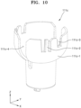
- FIG. 10 is a perspective view of the lens assembly accommodation portion illustrated in FIG. 2 .
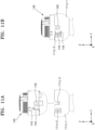
- FIGS. 11A and 11B are side views showing that the lens assembly 140 is coupled to the lens assembly accommodation portion of FIG. 10 .
- the lens assembly accommodation portion 111c may include a lens assembly accommodation portion body 111c-1 into which the lens assembly 140 is inserted and fixed. Furthermore, the lens assembly accommodation portion 111c may include a snap fit 111c-2 that is pivotably arranged on the lens assembly accommodation portion body 111c-1. In this state, in the lens assembly accommodation portion body 111c-1, a separate groove may be formed at both sides of the snap fit 111c-2 not to prevent the motion of the snap fit 111c-2 when the snap fit 111c-2 is moved.
- a rotation axis insertion groove 111c-3 into which the rotation axis 143 is inserted, may be formed in the lens assembly accommodation portion body 111c-1.
- a cable insertion groove 111c-4 into which a cable (not shown) of the lens assembly 140 is inserted, may be formed in the lens assembly accommodation portion body 111c-1.
- the lens assembly 140 may be separated from a lens bracket (not shown) and inserted into the lens assembly accommodation portion 111c.
- the lens assembly 140 may be arranged in the lens assembly accommodation portion 111c and then inserted into the lens assembly accommodation portion 111c.
- the rotation axis 143 may be inserted into the rotation axis insertion groove 111c-3.
- the stopper 144 may contact the snap fit 111c-2.
- the stopper 144 presses the snap fit 111c-2, and thus the snap fit 111c-2 may pivot.
- the stopper 144 passes over a part of the snap fit 111c-2, the snap fit 111c-2 may restrict the stopper 144.
- the stopper 144 may be caught by the protruding part of the snap fit 111c-2.
- the protruding portion of the snap fit 111c-2 is arranged at an end portion of the snap fit 111c-2, and after restricting the stopper 144, the stopper 144 may be prevented from escaping from the snap fit 111c-2.
- the cable of the lens assembly 140 may be drawn from the cable insertion groove 111c-4.
- the cable may be drawn from the side surface of the lens assembly accommodation portion 111c via the cable insertion groove 111c-4.
- the lens assembly 140 arranged on the rail 111a may be fixed to the lens assembly accommodation portion 111c arranged at the center of the rail 111a. Furthermore, in the security camera 100, the same lens assembly 140 may be commonly used in the rail 111a and the lens assembly accommodation portion 111c.
- the lens bracket may be rapidly and easily replaced.
- the other of the lens brackets may be arranged at desired positions on the rail.
- the position of the lens bracket may be firmly fixed after the position of the lens bracket is changed, an image at a position desired by the user may be obtained.
- the lens bracket may be rapidly and easily mounted.
- the position of the lens bracket may be prevented from being changed too fast during moving along the rail.
- the position of the lens bracket on the rail may be easily changed.
Landscapes
- Physics & Mathematics (AREA)
- Engineering & Computer Science (AREA)
- Multimedia (AREA)
- Signal Processing (AREA)
- General Physics & Mathematics (AREA)
- Optics & Photonics (AREA)
- Studio Devices (AREA)
- Accessories Of Cameras (AREA)
- Lens Barrels (AREA)
- Structure And Mechanism Of Cameras (AREA)
Description
- Exemplary embodiments/implementations of the invention relate generally to an apparatus and, more specifically, to a lens bracket for a security camera and a security camera having the same.
- General security cameras may photograph events occurring outside by using cameras. Recently, a security camera may have a plurality of lens assemblies to capture an image of an event occurring in various directions.
- Various structures may be employed to arrange a plurality of lens assemblies at various angles. A plurality of lens assemblies are generally fixed at particular positions in a housing using screws or bolts. In this case, when at least one of the lens assemblies is removed, positions of the other lens assemblies may not be changed, and thus a wide blind spot of a security camera may be generated.
- Furthermore, when a plurality of lens assemblies are used, the lens assemblies may be fixed at various positions. A housing needs to be changed to arrange each of the lens assemblies that are fixed at another position in the housing. In addition, the lens assemblies arranged at particular positions may not be able to be installed at other positions.
-
U.S. Patent Publication No. 2017-0299949 (Title of the Invention: Omnidirectional User Configurable Multi-Camera Housing, Applicant: Arecont Vision, LLC) discloses such a security camera. -
US 2015/0090849 A1 andUS 2013/160345 A1 disclose a lens bracket including a moving portion and a hooking portion. - The above information disclosed in this Background section is only for understanding of the background of the inventive concepts, and, therefore, it may contain information that does not constitute prior art.
- Devices constructed according to exemplary implementations of the invention include a lens bracket for a security camera and a security camera having the same.
- Additional features of the inventive concepts will be set forth in the description which follows, and in part will be apparent from the description, or may be learned by practice of the inventive concepts.
- According to one or more exemplary embodiments, a lens bracket is provided as defined in
claim 1. - The hooking portion may include a coupling connection portion protruding from the moving portion toward the rail, at least a part of the coupling connection portion being bent surrounding a side surface of the rail,; and a position fixing protrusion protruding from the coupling connection portion toward the rail protrusion of the rail.
- The coupling protrusion may protrude from the moving portion toward the rail, and at least a part of the coupling protrusion may be bent surrounding the rail.
- The moving portion may include a moving body portion, and a handle portion provided separately from the moving body portion, the hooking portion being connected to the handle portion.
- The lens bracket may further include a contact protrusion that protrudes from a lower surface of the moving portion toward the rail.
- According to one or more exemplary embodiments, a security camera include a lens assembly; a lens bracket into which a protruding portion of the lens assembly is rotatably inserted; and a stopper provided on the lens assembly and rotating in contact with the lens bracket during rotation of the lens assembly, wherein the stopper determines an angle range in which the protruding portion of the lens assembly is drawn from an open portion of the lens bracket and thus the lens assembly and the lens bracket are separated from each other.
- According to one or more exemplary embodiments, a security camera include: a lens assembly; the lens bracket as defined above into which a protruding portion of the lens assembly is rotatably inserted and to which the lens assembly is detachably connected; and a lens assembly accommodation portion spaced apart from the lens bracket, into which the lens assembly separated from the lens bracket is inserted and fixed.
- The lens assembly may include a stopper that determines an angle range in which the protruding portion of the lens assembly is drawn from an open portion of the lens bracket and thus the lens assembly and the lens bracket are separated from each other.
- The security camera may further include a rotation prevention portion that is provided on at least one of the lens bracket and the stopper.
- A part of the lens bracket that the stopper contacts may be curved.
- The lens assembly accommodation portion may include a snap fit into which the stopper is inserted and fixed.
- The lens assembly accommodation portion may include a rotation axis insertion groove into which a rotation axis of the lens assembly is inserted.
- The security camera may further comprise a rail detachably connected to the moving portion of the lens bracket. The rail may be annular in shape.
- The rail may include a rail protrusion protruding from an outer surface of the rail, the coupling protrusion of the lens bracket may be connected to an inner surface of the rail and the hooking portion may be configured to contact the rail protrusion of the rail. The inner surface is a surface that is closest to the lens assembly accommodation portion and the outer surface is a surface that is farthest from the lens assembly accommodation portion.
- The position fixing protrusion of the lens bracket may protrude from the coupling connection portion of the lens bracket toward the rail protrusion of the rail.
- The lens assembly may include a plurality of lens assemblies and the lens bracket includes a plurality of lens brackets, a circular rail is provided on which the plurality of lens brackets independently move, one of the plurality of lens assemblies is provided on the lens assembly accommodation portion located at a center of the rail, and other lens assemblies of the plurality of lens assemblies are provided on the plurality of lens brackets spaced apart from one another.
- It is to be understood that both the foregoing general description and the following detailed description are exemplary and explanatory and are intended to provide further explanation of the invention as claimed.
- The accompanying drawings, which are included to provide a further understanding of the invention and are incorporated in and constitute a part of this specification, illustrate exemplary embodiments of the invention, and together with the description serve to explain the inventive concepts.
-
FIG. 1 is a perspective view of a security camera according to an exemplary embodiment. -
FIG. 2 is a perspective view of a part of the security camera ofFIG. 1 . -
FIG. 3 is a perspective view of a lens bracket and a rail illustrated inFIG. 2 . -
FIG. 4 is a partial perspective view showing lower surfaces of the lens bracket and the rail ofFIG. 3 . -
FIG. 5 is a partial perspective view of the lower surface of the lens bracket ofFIG. 2 . -
FIG. 6 is a cross-sectional view of a part of the security camera ofFIG. 1 . -
FIG. 7 is an exploded perspective view of a lens assembly illustrated inFIG. 2 . -
FIG. 8 is an exploded perspective view of the lens bracket and the lens assembly ofFIG. 2 . -
FIGS. 9A and 9B are side views showing a coupling relationship between the lens bracket and the lens assembly illustrated inFIG. 7 . -
FIG. 10 is a perspective view of the lens assembly accommodation portion illustrated inFIG. 2 . -
FIGS. 11A and 11B are side views showing that the lens assembly is coupled to the lens assembly accommodation portion ofFIG. 10 . - In the following description, for the purposes of explanation, numerous specific details are set forth in order to provide a thorough understanding of various exemplary embodiments or implementations of the invention. As used herein "embodiments" and "implementations" are interchangeable words that are non-limiting examples of devices or methods employing one or more of the inventive concepts disclosed herein. It is apparent, however, that various exemplary embodiments may be practiced without these specific details or with one or more equivalent arrangements. In other instances, well-known structures and devices are shown in block diagram form in order to avoid unnecessarily obscuring various exemplary embodiments. Further, various exemplary embodiments may be different, but do not have to be exclusive. For example, specific shapes, configurations, and characteristics of an exemplary embodiment may be used or implemented in another exemplary embodiment without departing from the inventive concepts.
- Unless otherwise specified, the illustrated exemplary embodiments are to be understood as providing exemplary features of varying detail of some ways in which the inventive concepts may be implemented in practice. Therefore, unless otherwise specified, the features, components, modules, layers, films, panels, regions, and/or aspects, etc. (hereinafter individually or collectively referred to as "elements"), of the various embodiments may be otherwise combined, separated, interchanged, and/or rearranged without departing from the inventive concepts.
- The use of cross-hatching and/or shading in the accompanying drawings is generally provided to clarify boundaries between adjacent elements. As such, neither the presence nor the absence of cross-hatching or shading conveys or indicates any preference or requirement for particular materials, material properties, dimensions, proportions, commonalities between illustrated elements, and/or any other characteristic, attribute, property, etc., of the elements, unless specified. Further, in the accompanying drawings, the size and relative sizes of elements may be exaggerated for clarity and/or descriptive purposes. When an exemplary embodiment may be implemented differently, a specific process order may be performed differently from the described order. For example, two consecutively described processes may be performed substantially at the same time or performed in an order opposite to the described order. Also, like reference numerals denote like elements.
- When an element, such as a layer, is referred to as being "on," "connected to," or "coupled to" another element, it may be directly on, connected to, or coupled to the other element or intervening elements may be present. When, however, an element is referred to as being "directly on," "directly connected to," or "directly coupled to" another element, there are no intervening elements present. To this end, the term "connected" may refer to physical, electrical, and/or fluid connection, with or without intervening elements. Further, the D1-axis, the D2-axis, and the D3-axis are not limited to three axes of a rectangular coordinate system, such as the x, y, and z - axes, and may be interpreted in a broader sense. For example, the D1-axis, the D2-axis, and the D3-axis may be perpendicular to one another, or may represent different directions that are not perpendicular to one another. For the purposes of this disclosure, "at least one of X, Y, and Z" and "at least one selected from the group consisting of X, Y, and Z" may be construed as X only, Y only, Z only, or any combination of two or more of X, Y, and Z, such as, for instance, XYZ, XYY, YZ, and ZZ. As used herein, the term "and/or" includes any and all combinations of one or more of the associated listed items.
- Although the terms "first," "second," etc. may be used herein to describe various types of elements, these elements should not be limited by these terms. These terms are used to distinguish one element from another element. Thus, a first element discussed below could be termed a second element without departing from the teachings of the disclosure.
- Spatially relative terms, such as "beneath," "below," "under," "lower," "above," "upper," "over," "higher," "side" (e.g., as in "sidewall"), and the like, may be used herein for descriptive purposes, and, thereby, to describe one elements relationship to another element(s) as illustrated in the drawings. Spatially relative terms are intended to encompass different orientations of an apparatus in use, operation, and/or manufacture in addition to the orientation depicted in the drawings. For example, if the apparatus in the drawings is turned over, elements described as "below" or "beneath" other elements or features would then be oriented "above" the other elements or features. Thus, the exemplary term "below" can encompass both an orientation of above and below. Furthermore, the apparatus may be otherwise oriented (e.g., rotated 90 degrees or at other orientations), and, as such, the spatially relative descriptors used herein interpreted accordingly.
- The terminology used herein is for the purpose of describing particular embodiments and is not intended to be limiting. As used herein, the singular forms, "a," "an," and "the" are intended to include the plural forms as well, unless the context clearly indicates otherwise. Moreover, the terms "comprises," "comprising," "includes," and/or "including," when used in this specification, specify the presence of stated features, integers, steps, operations, elements, components, and/or groups thereof, but do not preclude the presence or addition of one or more other features, integers, steps, operations, elements, components, and/or groups thereof. It is also noted that, as used herein, the terms "substantially," "about," and other similar terms, are used as terms of approximation and not as terms of degree, and, as such, are utilized to account for inherent deviations in measured, calculated, and/or provided values that would be recognized by one of ordinary skill in the art.
- Various exemplary embodiments are described herein with reference to sectional and/or exploded illustrations that are schematic illustrations of idealized exemplary embodiments and/or intermediate structures. As such, variations from the shapes of the illustrations as a result, for example, of manufacturing techniques and/or tolerances, are to be expected. Thus, exemplary embodiments disclosed herein should not necessarily be construed as limited to the particular illustrated shapes of regions, but are to include deviations in shapes that result from, for instance, manufacturing. In this manner, regions illustrated in the drawings may be schematic in nature and the shapes of these regions may not reflect actual shapes of regions of a device and, as such, are not necessarily intended to be limiting.
- Unless otherwise defined, all terms (including technical and scientific terms) used herein have the same meaning as commonly understood by one of ordinary skill in the art to which this disclosure is a part. Terms, such as those defined in commonly used dictionaries, should be interpreted as having a meaning that is consistent with their meaning in the context of the relevant art and should not be interpreted in an idealized or overly formal sense, unless expressly so defined herein.
-
FIG. 1 is a perspective view of asecurity camera 100 according to an exemplary embodiment.FIG. 2 is a perspective view of a part of thesecurity camera 100 ofFIG. 1 . - Referring to
FIGS. 1 and2 , thesecurity camera 100 may include abase housing 111, a fixedhousing 112, acover housing 113, and acover 130. Thesecurity camera 100 further includes alens bracket 120 and alens assembly 140. - The
lens bracket 120 may be arranged on thebase housing 111. Furthermore, thebase housing 111 may be fixed on the fixedhousing 112. In this state, thebase housing 111 may include arail 111a on which thelens bracket 120 is arranged, a basehousing body portion 111b on which therail 111a is arranged, and a lensassembly accommodation portion 111c arranged at a center of the basehousing body portion 111b. - The
rail 111a may have an annular shape. Furthermore, a lower surface of therail 111a may be formed uneven. For example, therail 111a may include arail protrusion 111a-1 protruding from the lower surface thereof. In this state, therail protrusion 111a-1 may include a plurality of rail protrusions, and therail protrusions 111a-1 may be arranged on the lower surface of therail 111a around the outer periphery of therail 111a. Each of therail protrusions 111a-1 may be arranged on the lower surface of therail 111a such that a lengthwise direction of each of therail protrusions 111a-1 directs to the center of therail 111a. - The base
housing body portion 111b may be arranged on the lower surface of therail 111a. In this state, therail 111a may be spaced apart from an upper surface of the basehousing body portion 111b. The basehousing body portion 111b may be provided with afirst groove 111b-1 for inserting or removing when thelens bracket 120 is coupled to therail 111a or separated from therail 111a. Thefirst groove 111b-1 may be indented from an outer surface of the basehousing body portion 111b toward a center portion of the basehousing body portion 111b. - The lens
assembly accommodation portion 111c may be located at the center of therail 111a and in which one of a plurality of thelens assemblies 140 may be arranged. In this case, the lensassembly accommodation portion 111c may be coupled to thelens assembly 140 in various forms of inserting thelens assembly 140 therein or fixing thelens assembly 140 thereto. Furthermore, the lensassembly accommodation portion 111c may be formed integrally with the basehousing body portion 111b, or separately from the basehousing body portion 111b and coupled to the basehousing body portion 111b. When the basehousing body portion 111b and the lensassembly accommodation portion 111c are separately coupled to each other, the basehousing body portion 111b and the lensassembly accommodation portion 111c may be coupled by various methods. In an exemplary embodiment, the basehousing body portion 111b and the lensassembly accommodation portion 111c may be connected to each other using various members such as screws or bolts. In another exemplary embodiment, a protrusion such as a hook is formed on one of the basehousing body portion 111b and the lensassembly accommodation portion 111c and a recess for accommodating the protrusion is formed in the other one of the basehousing body portion 111b and the lensassembly accommodation portion 111c, and then as the protrusion is inserted into the recess, the basehousing body portion 111b and the lensassembly accommodation portion 111c may be coupled to each other. In the following description, for convenience of explanation, a case in which the basehousing body portion 111b and the lensassembly accommodation portion 111c are separately formed and coupled to each other is mainly described in detail. - The
base housing 111 may be coupled to the fixedhousing 112. In this state, the fixedhousing 112 may be fixed to an outer wall of a building. In this state, the fixedhousing 112 may be fixed using bolts or screws. Thebase housing 111 and the fixedhousing 112 may be coupled by various methods. For example, thebase housing 111 and the fixedhousing 112 may be coupled to each other using bolts, screws, or pins. In another exemplary embodiment, thebase housing 111 may be pivotably coupled to the fixedhousing 112 and may be connected to the fixedhousing 112 using a hook. - The
cover housing 113 is coupled to at least one of the fixedhousing 112 and thebase housing 111 and may fix thecover 130. In this state, thecover housing 113 may shield a part of thecover 130 and may shield the fixedhousing 112 and thebase housing 111. - The
lens bracket 120 may be detachably coupled to therail 111a. Thelens bracket 120 may be coupled to therail 111a to be movable along therail 111a. - The
cover 130 may be coupled to thebase housing 111 and may shield parts arranged between thecover 130 and thebase housing 111 from the outside. Thecover 130 may include acover body portion 131 and aforce applying portion 132. - The
cover body portion 131 may have a dome shape with a partially flat portion. For example, in thecover body portion 131, a side portion of thebase housing 111 may be formed to be curved and one surface of thecover body portion 131 facing the ground may be formed to be flat. Thecover body portion 131 may be formed of a transparent material such as acryl, glass, or plastic. Furthermore, a sealing member may be provided between thecover body portion 131 and thebase housing 111 to prevent intrusion of moisture from the outside. Thecover body portion 131 and thebase housing 111 may be coupled to each other by various methods. In an exemplary embodiment, thecover body portion 131 and thebase housing 111 may be fixed using a separate clamp. In another exemplary embodiment, a protrusion may be formed on one of thecover body portion 131 and thebase housing 111, and a groove or hole for accommodating the protrusion may be formed in the other one of thecover body portion 131 and thebase housing 111. Accordingly, as the protrusion is inserted into the groove or hole, thecover body portion 131 and thebase housing 111 may be coupled to each other. - The
force applying portion 132 may protrude from thecover body portion 131 toward thelens bracket 120. In this state, theforce applying portion 132 may be integrally formed with thecover body portion 131, or separately from thecover body portion 131 and coupled to thecover body portion 131. When theforce applying portion 132 is integrally formed with thecover body portion 131, theforce applying portion 132 may be formed of the same material as thecover body portion 131. When theforce applying portion 132 is formed separately from thecover body portion 131, theforce applying portion 132 may be coupled to thecover body portion 131 using a separate adhesive member. In this state, theforce applying portion 132 may be formed of an elastic material such as rubber, silicon, or plastic. In the following description, for convenience of explanation, a case in which theforce applying portion 132 is formed separately from thecover body portion 131 and coupled to theforce applying portion 132 is mainly described in detail. - The
lens assembly 140 may be coupled to at least one of the lensassembly accommodation portion 111c and thelens bracket 120. In this state, thelens assembly 140 may include a plurality of lens assemblies, in which one of thelens assemblies 140 may be coupled to the lensassembly accommodation portion 111c and the others may be coupled to thelens bracket 120. In this case, thelens bracket 120 may include a plurality of lens brackets corresponding to the number oflens assemblies 140. -
FIG. 3 is a perspective view of thelens bracket 120 and therail 111a illustrated inFIG. 2 .FIG. 4 is a partial perspective view showing lower surfaces of thelens bracket 120 and therail 111a ofFIG. 3 .FIG. 5 is a partial perspective view of the lower surface of thelens bracket 120 ofFIG. 2 .FIG. 6 is a cross-sectional view of a part of thesecurity camera 100 ofFIG. 1 . - Referring to
FIGS. 3 to 6 , thelens bracket 120 includes a fixedportion 121, a movingportion 122, acoupling protrusion 123, a hookingportion 124 and aguide 125. Thelens bracket 120 may further include acontact protrusion 126 and apartition wall 127. - The
lens assembly 140 may be fixedly inserted into fixedportion 121. In this state, the fixedportion 121 may protrude from the movingportion 122 toward thecover 130. The fixedportion 121 may be connected to thelens assembly 140 by various methods. For example, a hole, into which a part of thelens assembly 140 is inserted, is formed in the fixedportion 121, and as the part of thelens assembly 140 is inserted into the hole, thelens assembly 140 may be coupled to the fixedportion 121. In another exemplary embodiment, the fixedportion 121 may include aninsertion groove 121a along which the part of thelens assembly 140 may be removed in a direction. In this case, as the part of thelens assembly 140 is inserted into or removed from theinsertion groove 121a, thelens assembly 140 may be coupled to or separated from the fixedportion 121. In another exemplary embodiment, thelens assembly 140 may be rotatably coupled to the fixedportion 121 using a pin. In the following description, however, for convenience of explanation, a case in which theinsertion groove 121a is formed in the fixedportion 121 and thelens assembly 140 is coupled to the fixedportion 121 is mainly described in detail. - The moving
portion 122 may include a movingbody portion 122a and ahandle portion 122b. The movingbody portion 122a may be parallel to an upper surface of therail 111a, for example, a surface facing a surface on which therail protrusion 111a-1 is formed. Furthermore, the movingbody portion 122a may have a partial fan shape having a diameter that is the same as or similar to that of therail 111a. In other words, the shape of the movingbody portion 122a may be the same as or similar to that of a portion of therail 111a. Thehandle portion 122b may be separated from the movingbody portion 122a, and one end of thehandle portion 122b may be connected to the movingbody portion 122a. In this case, thehandle portion 122b, when receiving a force, may pivot a certain distance (ex, a certain angle) around the movingbody portion 122a. Furthermore, ananti-slip portion 122c may be provided on a surface of thehandle portion 122b. Theanti-slip portion 122c may include a plurality of anti-slip protrusions (not shown) spaced apart from each other. In another exemplary embodiment, theanti-slip portion 122c may include a protrusion arranged on the surface of thehandle portion 122b. In another exemplary embodiment, theanti-slip portion 122c may have a roughness that is greater than that of the other portion of thehandle portion 122b. In the following description, for convenience of explanation, a case in which theanti-slip portion 122c includes the anti-slip protrusion is mainly described in detail. Theanti-slip portion 122c may be arranged on at least one surface of thehandle portion 122b. For example, theanti-slip portion 122c may be arranged on at least one of upper and lower surfaces of thehandle portion 122b. In the following description, for convenience of explanation, a case in which theanti-slip portion 122c is provided on both of the upper and lower surfaces of thehandle portion 122b is mainly described in detail. - The
coupling protrusion 123 is arranged on the movingportion 122, which may surround an inner surface of therail 111a. In this state, thecoupling protrusion 123 is formed to be bent and thus surrounds the inner surface of therail 111a and the lower surface of therail 111a. Thecoupling protrusion 123 may include at least one coupling protrusion. In particular, when thecoupling protrusion 123 includes a plurality of coupling protrusions, thecoupling protrusions 123 may be spaced apart from a lower surface of the movingportion 122. In the following description, for convenience of explanation, a case in which thecoupling protrusion 123 includes two coupling protrusions is mainly described in detail. In this case, a distance between thecoupling protrusions 123 may be greater than a width of a portion of thehandle portion 122b connected to the movingbody portion 122a. - The hooking
portion 124 is arranged on thehandle portion 122b. In this state, the hookingportion 124 may be provided between the twocoupling protrusions 123. In this case, the hookingportion 124 and the twocoupling protrusions 123 may be arranged in a triangular shape. As at least a part of the hookingportion 124 is formed to be bent, the hookingportion 124 may include acoupling connection portion 124a that is arranged to surround outer and lower surfaces of therail 111a. In this state, thecoupling connection portion 124a may be similar to thecoupling protrusion 123. The hookingportion 124 may include aposition fixing protrusion 124b that protrudes toward therail protrusion 111a-1. Theposition fixing protrusion 124b may contact the lower surface of therail 111a during moving of the movingportion 122. In particular, during the moving of the movingportion 122, theposition fixing protrusion 124b may contact therail protrusion 111a-1 or enter between therail protrusions 111a-1 that neighbor each other. Theposition fixing protrusion 124b may not only prevent the speed of the movingportion 122 from slowing down during the moving of the movingportion 122, but also fix the position of the movingportion 122, to a degree, after the moving of the movingportion 122. - The
guide 125 protrudes from the movingbody portion 122a. The protrusion may be toward therail 111a. In this state, theguide 125 may be arranged at a side surface of the movingbody portion 122a on which the hookingportion 124 is arranged. Theguide 125 may shield a side surface of therail 111a. Theguide 125 may be formed in various shapes. In an exemplary embodiment, theguide 125 may be arranged on at least a portion of a side surface of the movingbody portion 122a. In another exemplary embodiment, theguide 125 may include a plurality of guides, and theguides 125 may be spaced apart from each other on the side surface of the movingbody portion 122a. In the following description, for convenience of explanation, a case in which theguide 125 includes a plurality of guides and theguides 125 are spaced apart from each other is mainly described in detail. - The
contact protrusion 126 may be arranged on a lower surface of the movingbody portion 122a. In this state, thecontact protrusion 126 may protrude from the lower surface of the movingbody portion 122a toward therail 111a. When the movingportion 122 is stopped, thecontact protrusion 126 may have a point contact or a surface contact with therail 111a. Thecontact protrusion 126 may include a plurality of contact protrusions, and thecontact protrusions 126 may be arranged on the movingbody portion 122a to be spaced apart from each other. When the movingportion 122 is accommodated on therail 111a, thecontact protrusion 126 may allow theposition fixing protrusion 124b to contact therail protrusion 111a-1 or the lower surface of therail 111a between the neighboringrail protrusions 111a-1. - The
partition wall 127 may be formed integrally with or separately from the movingportion 122. In this state, when thepartition wall 127 is formed separately from the movingportion 122, thepartition wall 127 may be formed similar to the movingportion 122 and coupled to therail 111a and may perform a linear motion along therail 111a. For example, thepartition wall 127, similar to thelens bracket 120, may include the fixedportion 121, the movingportion 122, thecoupling protrusion 123, the hookingportion 124, theguide 125, and thecontact protrusion 126. In the following description, for convenience of explanation, a case in which thepartition wall 127 is integrally formed with the movingportion 122 is mainly described in detail. - The
partition wall 127 may be connected to the fixedportion 121. Furthermore, thepartition wall 127 may protrude from the movingbody portion 122a toward thecover 130. Thepartition wall 127 may include a pair of partition walls to face each other with respect to the movingportion 122. In this case, thepartition walls 127 may block part of light incident on thelens assembly 140 provided on the movingportion 122. Thepartition wall 127 may be radially arranged around thelens assembly 140. For example, each of thepartition walls 127 may be arranged to face the center of therail 111a. - The
lens bracket 120 as described above may be separated from therail 111a. In particular, when thelens brackets 120 are arranged on therail 111a, at least one of thelens brackets 120 may be removed from therail 111a because the position of thelens assembly 140 is changed or the number oflens assemblies 140 is adjusted. - In detail, when the
lens bracket 120 is separated from therail 111a, thehandle portion 122b may receive a force in a direction away from the upper surface of therail 111a. In this case, thehandle portion 122b may be bent in a direction away from the upper surface of therail 111a with respect to the movingbody portion 122a. The hookingportion 124 with thehandle portion 122b may be separated from therail 111a. For example, when thehandle portion 122b is bent as above, part of thecoupling connection portion 124a may be moved from the lower surface of therail 111a in a circumferential direction of therail 111a. In this state, thecoupling connection portion 124a may open parts of the lower and side surfaces of therail 111a. Furthermore, theposition fixing protrusion 124b may be completely separated from the lower surface of therail 111a. Furthermore, as thehandle portion 122b is continuously rotated as above, thelens bracket 120 may rotate around thecoupling protrusion 123 and may be separated from therail 111a. Then, thelens bracket 120 is moved in a direction toward the center of therail 111a, and thus thecoupling protrusion 123 may be separated from therail 111a. A place where thelens bracket 120 is separated from therail 111a may be thefirst groove 111b-1 of thebase housing 111, as described above. - As described above, when one of the
lens brackets 120 is separated from or arranged on therail 111a, at least one of thelens brackets 120 may be moved on therail 111a. - In a method of moving the
lens assembly 140 via thelens bracket 120, thelens bracket 120, which is coupled to therail 111a, may be moved along therail 111a. In this state, a user may apply a force to thehandle portion 122b toward therail 111a. In this case, thehandle portion 122b may be bent towards the upper surface of therail 111a, and thus the hookingportion 124 with thehandle portion 122b may be moved. In this case, theposition fixing protrusion 124b of the hookingportion 124 may be separated from therail protrusion 111a-1 formed on the lower surface of therail 111a or withdrawn from the groove between therail protrusions 111a-1. As such, when the hookingportion 124 performs a motion, theposition fixing protrusion 124b is released from therail protrusion 111a-1, and thus thelens bracket 120 may freely move along therail 111a. In this case, additionally, the user may move thelens bracket 120 on therail 111a without applying a force to thehandle portion 122b. In detail, when thelens bracket 120 is moved on therail 111a, theposition fixing protrusion 124b, which moves with thelens bracket 120, may contact an outer surface of therail protrusion 111a-1. In this state, the position of theposition fixing protrusion 124b may be changed by therail protrusion 111a-1, and thehandle portion 122b may be bent a certain distance according to the position of theposition fixing protrusion 124b. For example, when theposition fixing protrusion 124b is located at a position where therail protrusion 111a-1 is the thickest, thehandle portion 122b may be bent toward therail 111a, and when theposition fixing protrusion 124b is arranged in the groove between therail protrusions 111a-1, thehandle portion 122b may return to the original state. In this above state, during rotation of thelens bracket 120, thelens bracket 120 may not smoothly move on therail 111a due to theposition fixing protrusion 124b, but may prevent the position of thelens bracket 120 from being changed too fast. - The
contact protrusion 126 may prevent thelens bracket 120 from moving at a fast speed. In detail, as described above, when thelens bracket 120 moves on therail 111a, thecontact protrusion 126 may be arranged to face theposition fixing protrusion 124b and thus may apply a force to the movingportion 122 in a direction opposite to theposition fixing protrusion 124b. In particular, when thelens bracket 120 moves on therail 111a, thecontact protrusion 126 may contact the upper surface of therail 111a and may provide a frictional force to thelens bracket 120 during the moving of thelens bracket 120. Furthermore, when theposition fixing protrusion 124b moves along the outer surface of therail protrusion 111a-1, thecontact protrusion 126 may contact the upper surface of therail 111a. In addition to the above case, when a force is applied to the handle portion toward therail 111a, thecontact protrusion 126 may contact the upper surface of therail 111a. Due to the above contact, thecontact protrusion 126 may provide a certain degree of a frictional force to thelens bracket 120 during the moving of thelens bracket 120, and thus a rapid position change of thelens bracket 120 due to the fast speed of thelens bracket 120 may be prevented. When thelens bracket 120 is stopped, thecontact protrusion 126 with therail 111a may fix the position of thelens bracket 120. In detail, when thelens bracket 120 is stopped, theposition fixing protrusion 124b may be arranged between the neighboringrail protrusions 111a-1. In this state, since a distance between an end portion of theposition fixing protrusion 124b and an end portion of thecontact protrusion 126 is less than a distance from the thickest position of therail protrusion 111a-1 to the upper surface of therail 111a, when thelens bracket 120 starts to move, theposition fixing protrusion 124b may be prevented from moving along the outer surface of therail protrusion 111a-1 to a degree. In particular, in this case, when a force over a certain amount is not applied to thelens bracket 120, thelens bracket 120 may not be moved on therail 111a. - A user may arrange the
lens assembly 140 in thelens bracket 120 and then place thelens bracket 120 on therail 111a. In the coupling of thelens bracket 120 to therail 111a, thelens bracket 120 may be coupled to therail 111a by applying a force to thelens bracket 120 on the upper surface of therail 111a or by first coupling one of thecoupling protrusion 123 and the hookingportion 124 to therail 111a and then rotating thelens bracket 120. In detail, when thelens bracket 120 is placed on therail 111a and then a force is applied to thelens bracket 120, as thecoupling protrusion 123 and the hookingportion 124 are separated from each other in opposite directions, thelens bracket 120 may be coupled to therail 111a. In this state, since thecoupling protrusion 123 and the hookingportion 124 are elastic, at least one of an end portion of thecoupling protrusion 123 and an end portion of the hookingportion 124 may perform a rotational motion around thelens bracket 120. Furthermore, as the hookingportion 124 is connected to thehandle portion 122b, in the above case, thehandle portion 122b pivots with respect to the movingbody portion 122a, and thus a distance between the hookingportion 124 and thecoupling protrusion 123 may vary. In another exemplary embodiment, thelens bracket 120 may be coupled to therail 111a by rotating thelens bracket 120 after coupling one of thecoupling protrusion 123 and the hookingportion 124 to therail 111a. First, after thecoupling protrusion 123 is coupled to therail 111a, thelens bracket 120 may be rotated around thecoupling protrusion 123. In this state, the user may increase the distance between the hookingportion 124 and thecoupling protrusion 123 by bending thehandle portion 122b in an opposite direction to the rotation direction of thelens bracket 120. Furthermore, when the hookingportion 124 is first coupled to therail 111a, the user may rotate thelens bracket 120 around the hookingportion 124. In this state, when thecoupling protrusion 123 contacts therail 111a, the position of thehandle portion 122b is changed, and thus the distance between thecoupling protrusion 123 and the hookingportion 124 may vary. Accordingly, thelens bracket 120 may be coupled to therail 111a. - As described above, after changing the position thereof, the
lens bracket 120 may fix the position of thelens assembly 140. In this state, as described above, thelens bracket 120 may be fixed through thecover 130 after coupling of thebase housing 111, in addition to thecontact protrusion 126 and theposition fixing protrusion 124b. - In detail, when the arrangement of the
lens bracket 120 is completed, thelens assembly 140 may be shielded from the outside by coupling thebase housing 111 and thecover 130. In this state, when thecover 130 is coupled to thebase housing 111, theforce applying portion 132 provided on an inner surface of thecover 130 may contact part of thelens bracket 120 and apply a force to thelens bracket 120 toward therail 111a. For example, theforce applying portion 132 may be arranged to encircle the inner surface of a flat portion of thecover 130. In this state, when thecover 130 is coupled to thebase housing 111, theforce applying portion 132 may contact at least one of the fixedportion 121 and thepartition wall 127 of thelens bracket 120 and apply a force to at least one of the fixedportion 121 and thepartition wall 127. In this case, the thickness of theforce applying portion 132 may be greater than the distance between an end portion of one of the fixedportion 121 and thepartition wall 127 and the inner surface of the flat portion of thecover 130. When thecover 130 is coupled to thebase housing 111, theforce applying portion 132 may apply a force to one of the fixedportion 121 and thepartition wall 127 toward therail 111a, and thus thelens bracket 120 may be prevented from being moved along therail 111a by an external force. - Accordingly, the
lens bracket 120 may be rapidly and easily mounted on therail 111a. Furthermore, the position of thelens bracket 120, when thelens bracket 120 moves along therail 111a, may be prevented from being changed too fast on therail 111a. The position of thelens bracket 120 on therail 111a may be easily changed on therail 111a. - In the
security camera 100, thelens bracket 120 may be rapidly and easily replaced. Furthermore, in thesecurity camera 100, after separating at least one of thelens brackets 120 from therail 111a, the others of thelens brackets 120 may be arranged at desired positions on therail 111a. - In the
security camera 100, since the position of thelens bracket 120 is firmly fixed after the position of thelens bracket 120 is changed, an image at a position desired by a user may be obtained. -
FIG. 7 is an exploded perspective view of thelens assembly 140 ofFIG. 2 .FIG. 8 is an exploded perspective view of thelens bracket 120 and thelens assembly 140 ofFIG. 2 .FIGS. 9A and 9B are side views showing a coupling relationship between thelens bracket 120 and thelens assembly 140 illustrated inFIG. 7 . - Referring to
FIGS. 7 to 9 , thelens assembly 140 may include alens module 141, alens housing 142, a protruding portion forming arotation axis 143, astopper 144, arotation prevention portion 145, a housing circuit board (not shown), and a housing connector (not shown). In this state, all or some of thelens module 141, thelens housing 142, therotation axis 143, thestopper 144, and therotation prevention portion 145 may be formed integrally with one another. Furthermore, thelens module 141, thelens housing 142, therotation axis 143, thestopper 144, and therotation prevention portion 145 may be formed separately from one another. - The
lens module 141 may include alens case 141a, at least onelens 141b arranged inside thelens case 141a, and a sensor (not shown) arranged inside thelens case 141a and detecting an image input through thelens 141b. In this state, thelens case 141a may include a plurality of lens cases and thus thelens cases 141a may be coupled to one another using hooks. Thelens module 141 may include a circuit board (not shown) where the sensor is arranged and a connector (not shown) connected to the circuit board. - The
lens module 141 may be arranged in thelens housing 142. Thelens housing 142 may be formed in one body or may be separated into a plurality of pieces. In the following description, for convenience of explanation, a case in which thelens housing 142 includes a plurality of pieces is mainly described in detail. - The
lens housing 142 may include afirst lens housing 142a, into which thelens case 141a is inserted and to which thelens case 141a is coupled, and asecond lens housing 142b arranged to surround thefirst lens housing 142a and coupled to thefirst lens housing 142a. In this state, when thefirst lens housing 142a may include a lens case guide 147 that guides a movement of thelens case 141a when thelens case 141a is inserted into thefirst lens housing 142a. Thelens case guide 147 may be formed in a lengthwise direction of thefirst lens housing 142a (or in an insertion direction of the lens assembly 140). - The
lens case 141a, thefirst lens housing 142a, and thesecond lens housing 142b may be coupled to one another by various methods. For example, thelens case 141a, thefirst lens housing 142a, and thesecond lens housing 142b may be coupled using screws or bolts. In another exemplary embodiment, thelens case 141a, thefirst lens housing 142a, and thesecond lens housing 142b may be coupled to one another using a coupling protrusion (not shown) or a coupling hook (not shown) and a coupling groove (not shown) or a coupling hole (not shown) into which the coupling protrusion or the coupling hook are inserted. In another exemplary embodiment, thelens case 141a, thefirst lens housing 142a, and thesecond lens housing 142b may be coupled to one another using a ring member. In this state, the coupling method of thelens case 141a, thefirst lens housing 142a, and thesecond lens housing 142b is not limited to the above-described methods and may include a coupling method using all structures and apparatuses enabling coupling of different members. In the following description, for convenience of explanation, a case in which thelens case 141a, thefirst lens housing 142a, and thesecond lens housing 142b are coupled to one another using a hook and a hole is mainly described in detail. - The
lens case 141a may be inserted into thefirst lens housing 142a. Thefirst lens housing 142a may be inserted into thesecond lens housing 142b. In this state, thefirst lens housing 142a may include afirst coupling hook 142a-1 that is caught by an edge of thesecond lens housing 142b. Thesecond lens housing 142b may include asecond coupling hook 142b-1 that is caught by an edge of thelens case 141a. When thelens module 141 is inserted into thefirst lens housing 142a, thefirst coupling hook 142a-1 may be pressed toward thesecond lens housing 142b. In this state, thesecond lens housing 142b may separately include a catch member or a protrusion to catch thefirst coupling hook 142a-1. When thelens module 141 is inserted into thefirst lens housing 142a, the catch member and thefirst coupling hook 142a-1 are in close contact with each other to be firmly coupled to each other. Furthermore, thefirst lens housing 142a may be rotatably coupled to thesecond lens housing 142b. Accordingly, thelens assembly 140 and thefirst lens housing 142a may rotate inside thesecond lens housing 142b. - The
rotation axis 143 may be formed on thelens housing 142. For example, therotation axis 143 may protrude from thesecond lens housing 142b. In this state, therotation axis 143 may be inserted into theinsertion groove 121a of the fixedportion 121, and a diameter of an end portion of therotation axis 143 may be greater than a diameter of the other part of therotation axis 143. - The
stopper 144 may protrude from thelens housing 142. In particular, thestopper 144 may be formed on thesecond lens housing 142b. Thestopper 144 may have a long side in a lengthwise direction of the lens module 141 (or in a direction in which light is incident on thelens module 141, a direction along an optical axis of thelens 141b, or a first direction). In an exemplary embodiment, as thestopper 144 is partially bent, thestopper 144 may shield at least two surfaces of the fixedportion 121. For example, thestopper 144 may shield a side surface and an upper surface of the fixedportion 121. Accordingly, thestopper 144 may prevent thelens module 141 from being shaken during rotation of thelens module 141. In another exemplary embodiment, thestopper 144 may be formed as a flat surface perpendicular to the upper surface of the fixedportion 121. In this case, thestopper 144 does not have a part arranged corresponding to the side surface of the fixedportion 121 ofFIG. 8 . - As described above, when the
lens assembly 140 rotates, thestopper 144 may limit a separation angle at which thelens assembly 140 is separated from the fixedportion 121. For example, when thelens assembly 140 is within a particular angular range, thestopper 144 contacts with the fixedportion 121 and may prevent therotation axis 143 from being drawn from theinsertion groove 121a. In this state, the particular angular range may include an angle at which the light incident on thelens assembly 140 is not blocked by at least one of thebase housing 111, the fixedhousing 112, and thecover housing 113. For example, the particular angular range may be within about 180° from a position where at least one of thebase housing 111, the fixedhousing 112, and thecover housing 113 meets thecover 130. In other words, when the optical axis of thelens 141b is arranged on a surface parallel to the upper surface of thebase housing 111 or under the surface, thelens assembly 140 may be separated from the fixedportion 121. In this state, the angle of thelens assembly 140 may be measured in one of a clockwise direction and a counterclockwise direction based on a case when the optical axis of thelens 141b is parallel to the upper surface of thebase housing 111. - Furthermore, as described above, the
stopper 144 allows thelens assembly 140 to be separated from the fixedportion 121 only in a first direction in which theinsertion groove 121a is formed. In addition, in thestopper 144, a separation angle range of thelens assembly 140 may be limited according to the size of theinsertion groove 121a. For example, when thelens assembly 140 is within a separation angle range other than the above-described particular angular range, as thelens assembly 140 is drawn from the fixedportion 121, the progress of thestopper 144 is not interrupted by the fixedportion 121, and thus therotation axis 143 may be separated from theinsertion groove 121a. In this state, the separation angle range in which thelens assembly 140 is separated from the fixedportion 121 may be an angle range in which the progress of thestopper 144 is not interrupted by the fixedportion 121 even when thelens assembly 140 rotates, according to the width of theinsertion groove 121a. - The
rotation prevention portion 145 may be arranged on at least one of thestopper 144 and the fixedportion 121. In this state, therotation prevention portion 145 may be formed in various shapes. For example, therotation prevention portion 145 may include a frictional member that is arranged on at least one of thestopper 144 and the fixedportion 121. In this case, the frictional member may include rubber or silicon. In another exemplary embodiment, therotation prevention portion 145 may include a protrusion that is arranged on at least one of surfaces of thestopper 144 and the fixedportion 121. In this state, therotation prevention portion 145 may include a fine protrusion such that a portion of at least one of thestopper 144 and the fixedportion 121 contacting each other is rougher than the other portion thereof. Therotation prevention portion 145 may include gear teeth arranged on each of thestopper 144 and the fixedportion 121. - A
housing circuit board 148 may be arranged in thefirst lens housing 142a. In this state, thehousing circuit board 148 may be connected to the circuit board via the housing connector. Furthermore, the housing connector may be connected to acable 149. - As described above, the
lens assembly 140 may be separated from thelens bracket 120 or arranged on thelens bracket 120. For example, therotation axis 143 may be inserted into theinsertion groove 121a by drawing therotation axis 143 from theinsertion groove 121a of the fixedportion 121. In this case, in thelens assembly 140, when the optical axis of thelens 141b is in the separation angle range, therotation axis 143 may be drawn from theinsertion groove 121a or inserted into theinsertion groove 121a. When therotation axis 143 is inserted into thegroove 121a, thestopper 144 may contact an outer surface of the fixedportion 121. In this state, a part of thestopper 144 that contacts the fixedportion 121 is formed in the same direction as the first direction in which theinsertion groove 121a is formed, and thus no interference with the fixedportion 121 occurs when therotation axis 143 is inserted into or drawn from theinsertion groove 121a. - An entrance portion of the
insertion groove 121a through which therotation axis 143 is inserted or drawn may be formed to guide therotation axis 143 to the inside of theinsertion groove 121a. For example, the size of the outermost end of the entrance portion of theinsertion groove 121a may be greater than the size of the inside of theinsertion groove 121a. In this case, theinsertion groove 121a may be formed to have a size that decreases by a certain length in the entrance portion and then increases to a certain size. In other words, in theinsertion groove 121a, the entrance portion is formed greater than the other portion, and thus, even when therotation axis 143 is inserted into theinsertion groove 121a in various directions, therotation axis 143 may be easily guided to the inside of theinsertion groove 121a. In addition, since the entrance portion of theinsertion groove 121a is formed inclined, therotation axis 143 may be guided to the center portion of theinsertion groove 121a. - After the
rotation axis 143 is inserted into theinsertion groove 121a, thelens assembly 140 may be rotated. In this state, thestopper 144 may be moved along the outer surface of the fixedportion 121. In particular, since therotation prevention portion 145 is arranged between thestopper 144 and the fixedportion 121 and contacts the outer surface of the fixedportion 121, thelens assembly 140 may be prevented from rotating too fast, and further, when thelens assembly 140 stops rotating, thelens assembly 140 may be prevented from rotating due to the weight of thelens assembly 140, and thus the position of thelens assembly 140 may be fixed. - As described above, the outer surface of the fixed
portion 121 over which thestopper 144 moves may be formed curved. For example, the outer surface of the fixedportion 121 over which thestopper 144 moves may have an arc of a semicircle or a fan shape, or a part of an ellipse. In this state, the outer surface of the fixedportion 121 may guide a rotation path of thelens assembly 140. - Accordingly, in the
security camera 100, thelens assembly 140 may be easily and freely replaced. Furthermore, in thesecurity camera 100, thelens assembly 140 may be separated only in the separation angle range. -
FIG. 10 is a perspective view of the lens assembly accommodation portion illustrated inFIG. 2 .FIGS. 11A and 11B are side views showing that thelens assembly 140 is coupled to the lens assembly accommodation portion ofFIG. 10 . - Referring to
FIGS. 10 and11 , the lensassembly accommodation portion 111c may include a lens assemblyaccommodation portion body 111c-1 into which thelens assembly 140 is inserted and fixed. Furthermore, the lensassembly accommodation portion 111c may include a snap fit 111c-2 that is pivotably arranged on the lens assemblyaccommodation portion body 111c-1. In this state, in the lens assemblyaccommodation portion body 111c-1, a separate groove may be formed at both sides of the snap fit 111c-2 not to prevent the motion of the snap fit 111c-2 when the snap fit 111c-2 is moved. A rotationaxis insertion groove 111c-3, into which therotation axis 143 is inserted, may be formed in the lens assemblyaccommodation portion body 111c-1. Furthermore, acable insertion groove 111c-4, into which a cable (not shown) of thelens assembly 140 is inserted, may be formed in the lens assemblyaccommodation portion body 111c-1. - As described above, the
lens assembly 140 may be separated from a lens bracket (not shown) and inserted into the lensassembly accommodation portion 111c. - In detail, after being separated from the
lens bracket 120, thelens assembly 140 may be arranged in the lensassembly accommodation portion 111c and then inserted into the lensassembly accommodation portion 111c. In this state, therotation axis 143 may be inserted into the rotationaxis insertion groove 111c-3. Furthermore, thestopper 144 may contact the snap fit 111c-2. In this case, when thelens assembly 140 is continuously inserted into the lensassembly accommodation portion 111c, thestopper 144 presses the snap fit 111c-2, and thus the snap fit 111c-2 may pivot. Then, when thestopper 144 passes over a part of the snap fit 111c-2, the snap fit 111c-2 may restrict thestopper 144. In this state, as a part of the snap fit 111c-2 protrudes, thestopper 144 may be caught by the protruding part of the snap fit 111c-2. In particular, the protruding portion of the snap fit 111c-2 is arranged at an end portion of the snap fit 111c-2, and after restricting thestopper 144, thestopper 144 may be prevented from escaping from the snap fit 111c-2. - As described above, when the
lens assembly 140 is coupled to the lensassembly accommodation portion 111c, the cable of thelens assembly 140 may be drawn from thecable insertion groove 111c-4. In this state, the cable may be drawn from the side surface of the lensassembly accommodation portion 111c via thecable insertion groove 111c-4. - Accordingly, in the
security camera 100, thelens assembly 140 arranged on therail 111a may be fixed to the lensassembly accommodation portion 111c arranged at the center of therail 111a. Furthermore, in thesecurity camera 100, thesame lens assembly 140 may be commonly used in therail 111a and the lensassembly accommodation portion 111c. - As described above, in the security camera according to the above-described exemplary embodiment, the lens bracket may be rapidly and easily replaced.
- Furthermore, in the security camera according to the above-described exemplary embodiment, after at least one of a plurality of lens brackets is separated from the rail, the other of the lens brackets may be arranged at desired positions on the rail.
- In the security camera according to the above-described exemplary embodiment, since the position of the lens bracket may be firmly fixed after the position of the lens bracket is changed, an image at a position desired by the user may be obtained.
- According to the above-described exemplary embodiments, the lens bracket may be rapidly and easily mounted.
- Furthermore, according to the above-described exemplary embodiments, the position of the lens bracket may be prevented from being changed too fast during moving along the rail.
- According to the above-described exemplary embodiments, the position of the lens bracket on the rail may be easily changed.
- It should be understood that exemplary embodiments described herein should be considered in a descriptive sense only and not for purposes of limitation. Descriptions of features or aspects within each exemplary embodiment should typically be considered as available for other similar features or aspects in other exemplary embodiments.
- It is clear for a person skilled in the art that the disclosed embodiments can also be combined where possible.
Claims (15)
- A lens bracket comprising:a fixed portion (121) connectable to a lens assembly;a moving portion (122) connected to the fixed portion (121) and detachably connectable to a rail;a coupling protrusion (123) provided on the moving portion (122) and connectable to a rail;a hooking portion (124) provided on the moving portion (122), the hooking portion facing the coupling protrusion (123), and being configured to contact a connectable rail; and characterized in that it further comprisesa guide (125) that is spaced apart from the hooking portion (124) and protruding from the moving portion (122) being configured to extend along a surface of a connectable rail.
- The lens bracket of claim 1, wherein the hooking portion (124) comprises:a coupling connection portion (124a) protruding from the moving portion (122) toward a connectable rail, at least a part of the coupling connection portion being bent to form a space in which a connectable rail is insertable ; anda position fixing protrusion (124b) protruding from the coupling connection portion (124a) toward a connectable rail.
- The lens bracket of claim 1 or 2, wherein the coupling protrusion protrudes (123) from the moving portion toward the rail, and at least a part of the coupling protrusion (123) is bent to form a space in which a connectable rail is insertable
- The lens bracket of one of the preceding claims, wherein the moving portion (122) comprises:a moving body portion (122a); anda handle portion (122b) provided separately from the moving body portion (122a), the hooking portion (124) being connected to the handle portion (122b).
- The lens bracket of one of the preceding claims, further comprising a contact protrusion (126) that protrudes from a lower surface of the moving portion (122b) toward a connectable rail
- A security camera comprising:a lens assembly (140);a lens bracket (120) of one of claims 1 to 5, wherein a protruding portion (143) of the lens assembly (140) is rotatably inserted into the lens bracket (120) and the lens assembly (140) is detachably connected to the lens bracket (120); anda lens assembly accommodation portion (111c) spaced apart from the lens bracket (120) and surrounded by the lens bracket (120), the lens assembly being inserted and fixed into the lens assembly accommodation portion
- The security camera of claim 6, wherein the lens assembly (140) comprises a stopper (144) configured to determine a separation angle range in which the protruding portion (143) of the lens assembly (140) is drawn from an insertion groove (121a) of the lens bracket(120) to separate the lens assembly from the lens bracket.
- The security camera of claim 6 or 7, further comprising a rotation prevention portion (145) that is provided on at least one of the lens bracket (120) and the stopper (144)
- The security camera of claim 7, wherein a part of the lens bracket (120) that contacts the stopper (144) is curved
- The security camera of one of claims 7 to 9, wherein the lens assembly accommodation portion (111c) comprises a snap fit (111c-2) into which the stopper (144) of the lens assembly (140) is inserted and fixed i.
- The security camera of one of claims 7 to 10, wherein the lens assembly accommodation portion (111c) comprises a rotation axis insertion groove into which the protruding portion (143) of the lens assembly (140) is inserted.
- The security camera of one of claims 6 to 11, further comprising a rail (111a) detachably connected to the moving portion (122) of the lens bracket (120), and/or
wherein the rail (111a) is annular in shape. - The security camera of claim 12, wherein the rail (111a) includes a rail protrusion (111a-1) protruding from an outer surface of the rail (111a),the coupling protrusion (123) of the lens bracket (120) is connected to an inner surface of the rail (111a), andthe hooking portion (124) is configured to contact the rail protrusion (111a-1) of the rail (111a).
- The security camera of claim 13, wherein the position fixing protrusion (124b) of the lens bracket (120) protrudes from the coupling connection portion (124a) of the lens bracket (120) toward the rail protrusion (111a-1) of the rail (111a).
- The security camera of one of claims 6 to 14, wherein the lens assembly comprises a plurality of lens assemblies and the lens bracket comprises a plurality of lens brackets,a circular rail is provided on which the plurality of lens brackets independently move,one of the plurality of lens assemblies is provided on the lens assembly accommodation portion located at a center of the rail, andother lens assemblies of the plurality of lens assemblies are provided on the plurality of lens brackets spaced apart from one another.
Applications Claiming Priority (1)
| Application Number | Priority Date | Filing Date | Title |
|---|---|---|---|
| KR1020180047323A KR102525183B1 (en) | 2018-04-24 | 2018-04-24 | Security camera |
Publications (2)
| Publication Number | Publication Date |
|---|---|
| EP3561592A1 EP3561592A1 (en) | 2019-10-30 |
| EP3561592B1 true EP3561592B1 (en) | 2024-02-21 |
Family
ID=64901846
Family Applications (1)
| Application Number | Title | Priority Date | Filing Date |
|---|---|---|---|
| EP18212309.1A Active EP3561592B1 (en) | 2018-04-24 | 2018-12-13 | Lens bracket for security camera and security camera having the same |
Country Status (3)
| Country | Link |
|---|---|
| US (1) | US10495952B2 (en) |
| EP (1) | EP3561592B1 (en) |
| KR (1) | KR102525183B1 (en) |
Families Citing this family (5)
| Publication number | Priority date | Publication date | Assignee | Title |
|---|---|---|---|---|
| US11150543B2 (en) * | 2018-01-22 | 2021-10-19 | Hangzhou Hikvision Digital Technology Co., Ltd. | Transparent cover and imaging optical system |
| KR102621876B1 (en) * | 2018-11-09 | 2024-01-05 | 한화비전 주식회사 | Apparatus for capturing images |
| JP7245767B2 (en) * | 2019-12-23 | 2023-03-24 | 株式会社日立エルジーデータストレージ | Omnidirectional ranging device |
| CN110881100B (en) * | 2019-12-31 | 2025-06-24 | 华勤技术股份有限公司 | Lens module and electronic equipment |
| KR102544347B1 (en) * | 2022-12-23 | 2023-06-16 | 한화시스템 주식회사 | Tracking apparatus and tracking method using the same |
Family Cites Families (21)
| Publication number | Priority date | Publication date | Assignee | Title |
|---|---|---|---|---|
| KR100481522B1 (en) * | 2001-10-30 | 2005-04-07 | 삼성전자주식회사 | Structure for fixing lens |
| KR100558021B1 (en) * | 2004-03-05 | 2006-03-10 | 황의남 | Pan / Tilt Dome Camera |
| US7520684B2 (en) | 2006-02-13 | 2009-04-21 | Hewlett-Packard Development Company, L.P. | Camera mount |
| KR20080011962A (en) | 2006-08-01 | 2008-02-11 | 주식회사 비젼아이트 | Dome camera device |
| CN101493562A (en) * | 2008-01-21 | 2009-07-29 | 鸿富锦精密工业(深圳)有限公司 | Lens cone rotating-in device and lens cone positioning method |
| JP5426257B2 (en) * | 2009-07-03 | 2014-02-26 | 富士フイルム株式会社 | Lens barrel shift mechanism and projector |
| JP2011069886A (en) * | 2009-09-24 | 2011-04-07 | Canon Inc | Lens barrel and optical device |
| KR100997877B1 (en) | 2009-10-16 | 2010-12-02 | 박웅도 | Broadband security camera |
| JP5587105B2 (en) * | 2010-09-09 | 2014-09-10 | キヤノン株式会社 | Imaging device |
| US8769859B2 (en) | 2011-12-23 | 2014-07-08 | Sellmark Corporation | Firearm sight mount |
| JP6064458B2 (en) * | 2012-09-05 | 2017-01-25 | ソニー株式会社 | Imaging device |
| US20150090849A1 (en) | 2013-09-30 | 2015-04-02 | Covidien Lp | Medical device supporting apparatus |
| FR3017020B1 (en) | 2014-01-24 | 2017-04-28 | Teb | FIXING STAND FOR SURVEILLANCE CAMERA AND COMPLEMENTARY FIXING MEMBER. |
| US9438782B2 (en) | 2014-06-09 | 2016-09-06 | Arecont Vision, Llc. | Omnidirectional user configurable multi-camera housing |
| JP6094827B2 (en) * | 2014-09-24 | 2017-03-15 | パナソニックIpマネジメント株式会社 | Imaging device |
| KR101778284B1 (en) * | 2015-07-20 | 2017-09-14 | 주식회사 오토닉스 | Device for detachable fixing lens cover |
| CN110892322A (en) * | 2017-06-05 | 2020-03-17 | 威智伦公司 | dome camera |
| CN207070183U (en) * | 2017-08-16 | 2018-03-02 | 中磊电子(苏州)有限公司 | Network camera |
| US10645265B2 (en) * | 2017-08-31 | 2020-05-05 | Canon Kabushiki Kaisha | Image pickup apparatus |
| TWI649610B (en) * | 2017-09-19 | 2019-02-01 | 晶睿通訊股份有限公司 | Lens driving mechanism and related camera device |
| KR102350916B1 (en) * | 2017-12-19 | 2022-01-13 | 한화테크윈 주식회사 | Surveillance camera assembly and method for installing the same |
-
2018
- 2018-04-24 KR KR1020180047323A patent/KR102525183B1/en active Active
- 2018-11-21 US US16/198,712 patent/US10495952B2/en active Active
- 2018-12-13 EP EP18212309.1A patent/EP3561592B1/en active Active
Also Published As
| Publication number | Publication date |
|---|---|
| EP3561592A1 (en) | 2019-10-30 |
| US10495952B2 (en) | 2019-12-03 |
| KR20190123517A (en) | 2019-11-01 |
| KR102525183B1 (en) | 2023-04-25 |
| US20190324352A1 (en) | 2019-10-24 |
Similar Documents
| Publication | Publication Date | Title |
|---|---|---|
| EP3561592A1 (en) | Lens bracket for security camera and security camera having the same | |
| US10791254B2 (en) | Lens assembly for surveillance camera and surveillance camera including the same | |
| CN213690191U (en) | Optical path conversion module, camera module and portable terminal including the same | |
| CN108303776B (en) | Optical lens sets, imaging lenses and electronic devices | |
| US20190377238A1 (en) | Camera module | |
| CN110967783A (en) | Motor assembly for driving liquid lens, camera module and electronic equipment | |
| US10939021B2 (en) | Image pickup apparatus | |
| KR102911333B1 (en) | Window member and electronic apparatus comprising the same | |
| KR20180127606A (en) | Display device and manufacturing method thereof | |
| US20200310080A9 (en) | Optical mechanism | |
| CN112449092B (en) | Camera module | |
| CN113311640A (en) | Camera module and portable electronic device including the same | |
| CN214795524U (en) | Camera module | |
| CN212727177U (en) | Camera module and electronic device including the same | |
| CN219514165U (en) | Camera module | |
| EP3114518B1 (en) | Camera and lens module | |
| KR102300017B1 (en) | Camera module and portable electronic device including the same | |
| US20240061318A1 (en) | Aperture module and camera module including the same | |
| CN104285182B (en) | With reference to the imaging device of lens protector | |
| US20230185166A1 (en) | Camera | |
| CN113281950A (en) | Camera module and portable electronic device including the same | |
| CN109963001A (en) | Functional assembly, electronic device and control method thereof | |
| US20090235590A1 (en) | Sliding mechanism for use in portable electronic device | |
| US6731869B2 (en) | Electrical connecting structure in lens barrels of cameras | |
| US7845864B2 (en) | Cover assembly |
Legal Events
| Date | Code | Title | Description |
|---|---|---|---|
| PUAI | Public reference made under article 153(3) epc to a published international application that has entered the european phase |
Free format text: ORIGINAL CODE: 0009012 |
|
| STAA | Information on the status of an ep patent application or granted ep patent |
Free format text: STATUS: THE APPLICATION HAS BEEN PUBLISHED |
|
| AK | Designated contracting states |
Kind code of ref document: A1 Designated state(s): AL AT BE BG CH CY CZ DE DK EE ES FI FR GB GR HR HU IE IS IT LI LT LU LV MC MK MT NL NO PL PT RO RS SE SI SK SM TR |
|
| AX | Request for extension of the european patent |
Extension state: BA ME |
|
| STAA | Information on the status of an ep patent application or granted ep patent |
Free format text: STATUS: REQUEST FOR EXAMINATION WAS MADE |
|
| 17P | Request for examination filed |
Effective date: 20191125 |
|
| RBV | Designated contracting states (corrected) |
Designated state(s): AL AT BE BG CH CY CZ DE DK EE ES FI FR GB GR HR HU IE IS IT LI LT LU LV MC MK MT NL NO PL PT RO RS SE SI SK SM TR |
|
| STAA | Information on the status of an ep patent application or granted ep patent |
Free format text: STATUS: EXAMINATION IS IN PROGRESS |
|
| 17Q | First examination report despatched |
Effective date: 20211102 |
|
| RAP3 | Party data changed (applicant data changed or rights of an application transferred) |
Owner name: HANWHA VISION CO., LTD. |
|
| GRAP | Despatch of communication of intention to grant a patent |
Free format text: ORIGINAL CODE: EPIDOSNIGR1 |
|
| STAA | Information on the status of an ep patent application or granted ep patent |
Free format text: STATUS: GRANT OF PATENT IS INTENDED |
|
| INTG | Intention to grant announced |
Effective date: 20230920 |
|
| GRAS | Grant fee paid |
Free format text: ORIGINAL CODE: EPIDOSNIGR3 |
|
| GRAA | (expected) grant |
Free format text: ORIGINAL CODE: 0009210 |
|
| STAA | Information on the status of an ep patent application or granted ep patent |
Free format text: STATUS: THE PATENT HAS BEEN GRANTED |
|
| AK | Designated contracting states |
Kind code of ref document: B1 Designated state(s): AL AT BE BG CH CY CZ DE DK EE ES FI FR GB GR HR HU IE IS IT LI LT LU LV MC MK MT NL NO PL PT RO RS SE SI SK SM TR |
|
| REG | Reference to a national code |
Ref country code: GB Ref legal event code: FG4D |
|
| REG | Reference to a national code |
Ref country code: CH Ref legal event code: EP |
|
| REG | Reference to a national code |
Ref country code: DE Ref legal event code: R096 Ref document number: 602018065471 Country of ref document: DE |
|
| REG | Reference to a national code |
Ref country code: IE Ref legal event code: FG4D |
|
| REG | Reference to a national code |
Ref country code: LT Ref legal event code: MG9D |
|
| REG | Reference to a national code |
Ref country code: NL Ref legal event code: MP Effective date: 20240221 |
|
| PG25 | Lapsed in a contracting state [announced via postgrant information from national office to epo] |
Ref country code: IS Free format text: LAPSE BECAUSE OF FAILURE TO SUBMIT A TRANSLATION OF THE DESCRIPTION OR TO PAY THE FEE WITHIN THE PRESCRIBED TIME-LIMIT Effective date: 20240621 |
|
| PG25 | Lapsed in a contracting state [announced via postgrant information from national office to epo] |
Ref country code: LT Free format text: LAPSE BECAUSE OF FAILURE TO SUBMIT A TRANSLATION OF THE DESCRIPTION OR TO PAY THE FEE WITHIN THE PRESCRIBED TIME-LIMIT Effective date: 20240221 |
|
| PG25 | Lapsed in a contracting state [announced via postgrant information from national office to epo] |
Ref country code: GR Free format text: LAPSE BECAUSE OF FAILURE TO SUBMIT A TRANSLATION OF THE DESCRIPTION OR TO PAY THE FEE WITHIN THE PRESCRIBED TIME-LIMIT Effective date: 20240522 |
|
| REG | Reference to a national code |
Ref country code: AT Ref legal event code: MK05 Ref document number: 1659616 Country of ref document: AT Kind code of ref document: T Effective date: 20240221 |
|
| PG25 | Lapsed in a contracting state [announced via postgrant information from national office to epo] |
Ref country code: RS Free format text: LAPSE BECAUSE OF FAILURE TO SUBMIT A TRANSLATION OF THE DESCRIPTION OR TO PAY THE FEE WITHIN THE PRESCRIBED TIME-LIMIT Effective date: 20240521 Ref country code: HR Free format text: LAPSE BECAUSE OF FAILURE TO SUBMIT A TRANSLATION OF THE DESCRIPTION OR TO PAY THE FEE WITHIN THE PRESCRIBED TIME-LIMIT Effective date: 20240221 Ref country code: NL Free format text: LAPSE BECAUSE OF FAILURE TO SUBMIT A TRANSLATION OF THE DESCRIPTION OR TO PAY THE FEE WITHIN THE PRESCRIBED TIME-LIMIT Effective date: 20240221 |
|
| PG25 | Lapsed in a contracting state [announced via postgrant information from national office to epo] |
Ref country code: ES Free format text: LAPSE BECAUSE OF FAILURE TO SUBMIT A TRANSLATION OF THE DESCRIPTION OR TO PAY THE FEE WITHIN THE PRESCRIBED TIME-LIMIT Effective date: 20240221 |
|
| PG25 | Lapsed in a contracting state [announced via postgrant information from national office to epo] |
Ref country code: AT Free format text: LAPSE BECAUSE OF FAILURE TO SUBMIT A TRANSLATION OF THE DESCRIPTION OR TO PAY THE FEE WITHIN THE PRESCRIBED TIME-LIMIT Effective date: 20240221 |
|
| PG25 | Lapsed in a contracting state [announced via postgrant information from national office to epo] |
Ref country code: RS Free format text: LAPSE BECAUSE OF FAILURE TO SUBMIT A TRANSLATION OF THE DESCRIPTION OR TO PAY THE FEE WITHIN THE PRESCRIBED TIME-LIMIT Effective date: 20240521 Ref country code: NO Free format text: LAPSE BECAUSE OF FAILURE TO SUBMIT A TRANSLATION OF THE DESCRIPTION OR TO PAY THE FEE WITHIN THE PRESCRIBED TIME-LIMIT Effective date: 20240521 Ref country code: NL Free format text: LAPSE BECAUSE OF FAILURE TO SUBMIT A TRANSLATION OF THE DESCRIPTION OR TO PAY THE FEE WITHIN THE PRESCRIBED TIME-LIMIT Effective date: 20240221 Ref country code: LT Free format text: LAPSE BECAUSE OF FAILURE TO SUBMIT A TRANSLATION OF THE DESCRIPTION OR TO PAY THE FEE WITHIN THE PRESCRIBED TIME-LIMIT Effective date: 20240221 Ref country code: IS Free format text: LAPSE BECAUSE OF FAILURE TO SUBMIT A TRANSLATION OF THE DESCRIPTION OR TO PAY THE FEE WITHIN THE PRESCRIBED TIME-LIMIT Effective date: 20240621 Ref country code: HR Free format text: LAPSE BECAUSE OF FAILURE TO SUBMIT A TRANSLATION OF THE DESCRIPTION OR TO PAY THE FEE WITHIN THE PRESCRIBED TIME-LIMIT Effective date: 20240221 Ref country code: GR Free format text: LAPSE BECAUSE OF FAILURE TO SUBMIT A TRANSLATION OF THE DESCRIPTION OR TO PAY THE FEE WITHIN THE PRESCRIBED TIME-LIMIT Effective date: 20240522 Ref country code: FI Free format text: LAPSE BECAUSE OF FAILURE TO SUBMIT A TRANSLATION OF THE DESCRIPTION OR TO PAY THE FEE WITHIN THE PRESCRIBED TIME-LIMIT Effective date: 20240221 Ref country code: ES Free format text: LAPSE BECAUSE OF FAILURE TO SUBMIT A TRANSLATION OF THE DESCRIPTION OR TO PAY THE FEE WITHIN THE PRESCRIBED TIME-LIMIT Effective date: 20240221 Ref country code: BG Free format text: LAPSE BECAUSE OF FAILURE TO SUBMIT A TRANSLATION OF THE DESCRIPTION OR TO PAY THE FEE WITHIN THE PRESCRIBED TIME-LIMIT Effective date: 20240221 Ref country code: AT Free format text: LAPSE BECAUSE OF FAILURE TO SUBMIT A TRANSLATION OF THE DESCRIPTION OR TO PAY THE FEE WITHIN THE PRESCRIBED TIME-LIMIT Effective date: 20240221 |
|
| PG25 | Lapsed in a contracting state [announced via postgrant information from national office to epo] |
Ref country code: PL Free format text: LAPSE BECAUSE OF FAILURE TO SUBMIT A TRANSLATION OF THE DESCRIPTION OR TO PAY THE FEE WITHIN THE PRESCRIBED TIME-LIMIT Effective date: 20240221 Ref country code: PT Free format text: LAPSE BECAUSE OF FAILURE TO SUBMIT A TRANSLATION OF THE DESCRIPTION OR TO PAY THE FEE WITHIN THE PRESCRIBED TIME-LIMIT Effective date: 20240621 |
|
| PG25 | Lapsed in a contracting state [announced via postgrant information from national office to epo] |
Ref country code: SE Free format text: LAPSE BECAUSE OF FAILURE TO SUBMIT A TRANSLATION OF THE DESCRIPTION OR TO PAY THE FEE WITHIN THE PRESCRIBED TIME-LIMIT Effective date: 20240221 Ref country code: PT Free format text: LAPSE BECAUSE OF FAILURE TO SUBMIT A TRANSLATION OF THE DESCRIPTION OR TO PAY THE FEE WITHIN THE PRESCRIBED TIME-LIMIT Effective date: 20240621 Ref country code: PL Free format text: LAPSE BECAUSE OF FAILURE TO SUBMIT A TRANSLATION OF THE DESCRIPTION OR TO PAY THE FEE WITHIN THE PRESCRIBED TIME-LIMIT Effective date: 20240221 Ref country code: LV Free format text: LAPSE BECAUSE OF FAILURE TO SUBMIT A TRANSLATION OF THE DESCRIPTION OR TO PAY THE FEE WITHIN THE PRESCRIBED TIME-LIMIT Effective date: 20240221 |
|
| PG25 | Lapsed in a contracting state [announced via postgrant information from national office to epo] |
Ref country code: DK Free format text: LAPSE BECAUSE OF FAILURE TO SUBMIT A TRANSLATION OF THE DESCRIPTION OR TO PAY THE FEE WITHIN THE PRESCRIBED TIME-LIMIT Effective date: 20240221 |
|
| PG25 | Lapsed in a contracting state [announced via postgrant information from national office to epo] |
Ref country code: SM Free format text: LAPSE BECAUSE OF FAILURE TO SUBMIT A TRANSLATION OF THE DESCRIPTION OR TO PAY THE FEE WITHIN THE PRESCRIBED TIME-LIMIT Effective date: 20240221 |
|
| PG25 | Lapsed in a contracting state [announced via postgrant information from national office to epo] |
Ref country code: EE Free format text: LAPSE BECAUSE OF FAILURE TO SUBMIT A TRANSLATION OF THE DESCRIPTION OR TO PAY THE FEE WITHIN THE PRESCRIBED TIME-LIMIT Effective date: 20240221 Ref country code: CZ Free format text: LAPSE BECAUSE OF FAILURE TO SUBMIT A TRANSLATION OF THE DESCRIPTION OR TO PAY THE FEE WITHIN THE PRESCRIBED TIME-LIMIT Effective date: 20240221 |
|
| PG25 | Lapsed in a contracting state [announced via postgrant information from national office to epo] |
Ref country code: SK Free format text: LAPSE BECAUSE OF FAILURE TO SUBMIT A TRANSLATION OF THE DESCRIPTION OR TO PAY THE FEE WITHIN THE PRESCRIBED TIME-LIMIT Effective date: 20240221 |
|
| PG25 | Lapsed in a contracting state [announced via postgrant information from national office to epo] |
Ref country code: SM Free format text: LAPSE BECAUSE OF FAILURE TO SUBMIT A TRANSLATION OF THE DESCRIPTION OR TO PAY THE FEE WITHIN THE PRESCRIBED TIME-LIMIT Effective date: 20240221 Ref country code: SK Free format text: LAPSE BECAUSE OF FAILURE TO SUBMIT A TRANSLATION OF THE DESCRIPTION OR TO PAY THE FEE WITHIN THE PRESCRIBED TIME-LIMIT Effective date: 20240221 Ref country code: RO Free format text: LAPSE BECAUSE OF FAILURE TO SUBMIT A TRANSLATION OF THE DESCRIPTION OR TO PAY THE FEE WITHIN THE PRESCRIBED TIME-LIMIT Effective date: 20240221 Ref country code: EE Free format text: LAPSE BECAUSE OF FAILURE TO SUBMIT A TRANSLATION OF THE DESCRIPTION OR TO PAY THE FEE WITHIN THE PRESCRIBED TIME-LIMIT Effective date: 20240221 Ref country code: DK Free format text: LAPSE BECAUSE OF FAILURE TO SUBMIT A TRANSLATION OF THE DESCRIPTION OR TO PAY THE FEE WITHIN THE PRESCRIBED TIME-LIMIT Effective date: 20240221 Ref country code: CZ Free format text: LAPSE BECAUSE OF FAILURE TO SUBMIT A TRANSLATION OF THE DESCRIPTION OR TO PAY THE FEE WITHIN THE PRESCRIBED TIME-LIMIT Effective date: 20240221 |
|
| REG | Reference to a national code |
Ref country code: DE Ref legal event code: R097 Ref document number: 602018065471 Country of ref document: DE |
|
| PG25 | Lapsed in a contracting state [announced via postgrant information from national office to epo] |
Ref country code: IT Free format text: LAPSE BECAUSE OF FAILURE TO SUBMIT A TRANSLATION OF THE DESCRIPTION OR TO PAY THE FEE WITHIN THE PRESCRIBED TIME-LIMIT Effective date: 20240221 |
|
| PLBE | No opposition filed within time limit |
Free format text: ORIGINAL CODE: 0009261 |
|
| STAA | Information on the status of an ep patent application or granted ep patent |
Free format text: STATUS: NO OPPOSITION FILED WITHIN TIME LIMIT |
|
| PG25 | Lapsed in a contracting state [announced via postgrant information from national office to epo] |
Ref country code: IT Free format text: LAPSE BECAUSE OF FAILURE TO SUBMIT A TRANSLATION OF THE DESCRIPTION OR TO PAY THE FEE WITHIN THE PRESCRIBED TIME-LIMIT Effective date: 20240221 |
|
| 26N | No opposition filed |
Effective date: 20241122 |
|
| PG25 | Lapsed in a contracting state [announced via postgrant information from national office to epo] |
Ref country code: SI Free format text: LAPSE BECAUSE OF FAILURE TO SUBMIT A TRANSLATION OF THE DESCRIPTION OR TO PAY THE FEE WITHIN THE PRESCRIBED TIME-LIMIT Effective date: 20240221 |
|
| PG25 | Lapsed in a contracting state [announced via postgrant information from national office to epo] |
Ref country code: MC Free format text: LAPSE BECAUSE OF FAILURE TO SUBMIT A TRANSLATION OF THE DESCRIPTION OR TO PAY THE FEE WITHIN THE PRESCRIBED TIME-LIMIT Effective date: 20240221 |
|
| REG | Reference to a national code |
Ref country code: CH Ref legal event code: PL |
|
| PG25 | Lapsed in a contracting state [announced via postgrant information from national office to epo] |
Ref country code: LU Free format text: LAPSE BECAUSE OF NON-PAYMENT OF DUE FEES Effective date: 20241213 |
|
| REG | Reference to a national code |
Ref country code: BE Ref legal event code: MM Effective date: 20241231 |
|
| PG25 | Lapsed in a contracting state [announced via postgrant information from national office to epo] |
Ref country code: BE Free format text: LAPSE BECAUSE OF NON-PAYMENT OF DUE FEES Effective date: 20241231 |
|
| PG25 | Lapsed in a contracting state [announced via postgrant information from national office to epo] |
Ref country code: FR Free format text: LAPSE BECAUSE OF NON-PAYMENT OF DUE FEES Effective date: 20241231 |
|
| PG25 | Lapsed in a contracting state [announced via postgrant information from national office to epo] |
Ref country code: CH Free format text: LAPSE BECAUSE OF NON-PAYMENT OF DUE FEES Effective date: 20241231 |
|
| PG25 | Lapsed in a contracting state [announced via postgrant information from national office to epo] |
Ref country code: IE Free format text: LAPSE BECAUSE OF NON-PAYMENT OF DUE FEES Effective date: 20241213 |
|
| PGFP | Annual fee paid to national office [announced via postgrant information from national office to epo] |
Ref country code: DE Payment date: 20251120 Year of fee payment: 8 |
|
| PGFP | Annual fee paid to national office [announced via postgrant information from national office to epo] |
Ref country code: GB Payment date: 20251120 Year of fee payment: 8 |
|
| PG25 | Lapsed in a contracting state [announced via postgrant information from national office to epo] |
Ref country code: CY Free format text: LAPSE BECAUSE OF FAILURE TO SUBMIT A TRANSLATION OF THE DESCRIPTION OR TO PAY THE FEE WITHIN THE PRESCRIBED TIME-LIMIT Effective date: 20240221 |