EP3561473A1 - A composite structure with damage location capability and method for manufacturing a composite structure with damage location capability - Google Patents
A composite structure with damage location capability and method for manufacturing a composite structure with damage location capability Download PDFInfo
- Publication number
- EP3561473A1 EP3561473A1 EP18382280.8A EP18382280A EP3561473A1 EP 3561473 A1 EP3561473 A1 EP 3561473A1 EP 18382280 A EP18382280 A EP 18382280A EP 3561473 A1 EP3561473 A1 EP 3561473A1
- Authority
- EP
- European Patent Office
- Prior art keywords
- damage
- optical fiber
- composite part
- fiber sensor
- composite
- Prior art date
- Legal status (The legal status is an assumption and is not a legal conclusion. Google has not performed a legal analysis and makes no representation as to the accuracy of the status listed.)
- Withdrawn
Links
- 239000002131 composite material Substances 0.000 title claims abstract description 135
- 238000000034 method Methods 0.000 title claims abstract description 18
- 238000004519 manufacturing process Methods 0.000 title claims abstract description 16
- 239000013307 optical fiber Substances 0.000 claims abstract description 71
- 238000012545 processing Methods 0.000 claims abstract description 20
- 230000003287 optical effect Effects 0.000 claims abstract description 13
- 238000006073 displacement reaction Methods 0.000 claims abstract description 6
- 230000007704 transition Effects 0.000 claims description 20
- 239000000853 adhesive Substances 0.000 claims description 7
- 230000001070 adhesive effect Effects 0.000 claims description 7
- 238000004891 communication Methods 0.000 claims description 4
- 238000007689 inspection Methods 0.000 description 13
- 230000007547 defect Effects 0.000 description 8
- 239000000835 fiber Substances 0.000 description 4
- 238000001514 detection method Methods 0.000 description 3
- 238000005259 measurement Methods 0.000 description 3
- 238000012544 monitoring process Methods 0.000 description 3
- 230000006978 adaptation Effects 0.000 description 1
- 238000010924 continuous production Methods 0.000 description 1
- 230000032798 delamination Effects 0.000 description 1
- 230000001066 destructive effect Effects 0.000 description 1
- 238000005516 engineering process Methods 0.000 description 1
- 230000005284 excitation Effects 0.000 description 1
- 230000009474 immediate action Effects 0.000 description 1
- 239000000463 material Substances 0.000 description 1
- 238000006116 polymerization reaction Methods 0.000 description 1
- 239000002520 smart material Substances 0.000 description 1
- 230000001960 triggered effect Effects 0.000 description 1
- 238000009966 trimming Methods 0.000 description 1
- 238000002604 ultrasonography Methods 0.000 description 1
Images













Classifications
-
- G—PHYSICS
- G01—MEASURING; TESTING
- G01M—TESTING STATIC OR DYNAMIC BALANCE OF MACHINES OR STRUCTURES; TESTING OF STRUCTURES OR APPARATUS, NOT OTHERWISE PROVIDED FOR
- G01M11/00—Testing of optical apparatus; Testing structures by optical methods not otherwise provided for
- G01M11/08—Testing mechanical properties
- G01M11/083—Testing mechanical properties by using an optical fiber in contact with the device under test [DUT]
- G01M11/086—Details about the embedment of the optical fiber within the DUT
-
- G—PHYSICS
- G01—MEASURING; TESTING
- G01M—TESTING STATIC OR DYNAMIC BALANCE OF MACHINES OR STRUCTURES; TESTING OF STRUCTURES OR APPARATUS, NOT OTHERWISE PROVIDED FOR
- G01M5/00—Investigating the elasticity of structures, e.g. deflection of bridges or air-craft wings
- G01M5/0033—Investigating the elasticity of structures, e.g. deflection of bridges or air-craft wings by determining damage, crack or wear
-
- G—PHYSICS
- G01—MEASURING; TESTING
- G01M—TESTING STATIC OR DYNAMIC BALANCE OF MACHINES OR STRUCTURES; TESTING OF STRUCTURES OR APPARATUS, NOT OTHERWISE PROVIDED FOR
- G01M5/00—Investigating the elasticity of structures, e.g. deflection of bridges or air-craft wings
- G01M5/0016—Investigating the elasticity of structures, e.g. deflection of bridges or air-craft wings of aircraft wings or blades
Definitions
- the present invention refers to a composite structure adapted to identify and localize a damage, such as a disbond or delamination occurred in a composite part.
- One object of the present invention is to provide a composite structure capable of performing an immediate detection and an accurate location of a damage present in a composite part. It is also an object of the invention to characterize the detected damage in order to be able of performing a diagnostic of the damage.
- Another object of the invention is to provide a composite structure capable of lowering the downtime caused by the current inspection of composite parts, and minimizing the need of such inspections, which usually involve unwanted costs and workload.
- the invention also refers to a method for manufacturing a composite structure with damage location capability.
- Another object of the invention is to provide a composite structure that is compatible with the manufacturing conditions of composite parts to easy the adaptations required in these composite parts.
- NDI Non Destructive Inspections
- optical fiber sensors are increasingly advancing with regard to other conventional instruments, becoming one of the best solution for some applications.
- the present invention overcomes the above mentioned drawbacks by providing a composite structure with damage location capability, and a method for manufacturing a composite structure with damage location capability, which reduces the costs and disturbances derived by damaged structures.
- One aspect of the present invention refers to a composite structure with damage location capability that comprises at least one composite part having an area to be monitored, at least one optical fiber sensor in contact with at least the area to be monitored and deployed following a direction, and a processing data unit in communication with the at least one optical fiber sensor.
- the processing data unit is adapted to:
- Equipping a composite part with an optical fiber sensor and a processing data unit configured as mentioned above, provides a permanent damage inspection in said composite part.
- This on-board inspection allows an immediate detection of damage, avoiding the appearance of unexpected damages, and thus the downtime, workload and costs caused by the scheduled and unscheduled inspection of composite parts.
- the invention provides precise location of the detected damages. This way, the invention offers valuable information for the diagnostic of the damage and for the repairing tasks.
- the processing data unit may be further adapted to obtain the size of the identified damage from the value of the distance that each peak of the strain signal has been displaced with respect to the location of said peak in a reference signal associated to the target area in an undamaged composite part.
- processing data unit may be further adapted to obtain the residual strength of the composite part from the size of the identified damage.
- the composite structure is adapted to shape or characterize the detected damage.
- the invention offers valuable information to make a diagnostic of the damage to know how severe is, and if so, if an immediate action to restore load capacity is required.
- the target area may comprise a transition area in the at least one composite part. Transition areas have different thickness and/or stiffness properties with respect to their adjacent areas. Usually, these different properties are caused by structural discontinuities in the composite part. Other target areas may include glued joints and/or structural damages (possibly caused by impacts received during the service of an aircraft).
- the optical fiber sensor consists of multiplexed Bragg gratings or distributed sensing fiber based on the monitoring of the backscattering reflection.
- the invention contemplates an aircraft that comprises a composite structure with damage location capability as describe above.
- the damage detection can be performed off-line, when the aircraft is on ground, and on-line, in a continuous process during flight operation, in function of the configuration of the used processing data unit.
- Another aspect of the invention refers to a method for manufacturing a composite structure with damage location capability comprising the steps of providing at least one composite part having an area to be monitored, providing at least one optical fiber sensor and deploying it following a direction to be in contact with at least the area to be monitored, and providing a processing data unit, in communication with the at least one optical fiber sensor, and configuring the processing data unit to:
- the method of the invention provides a composite structure equipped with a processing data unit and at least one optical fiber sensor in contact with a composite part to provide information (optical information) from which a strain profile can be obtained.
- the method can be applied and used with independence of the curing composite process: co-cured, co-bonded or secondary bonded.
- the method of the invention is compatible with the conventional manufacture of composites, sharing manufacturing conditions, trimming process and final assembly line.
- the method of the invention provides a simple and cost-effective way of producing composite structures with damage location.
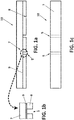
- Figures 1a-c shows different views of an undamaged composite part (10) that includes an upper layout (7), a lower layout (8), and an adhesive line (9) in between bonding the two layers (7, 8) together.
- the undamaged composite part (10) further includes two target areas (5) comprising transition areas. Transition areas have different thickness and/or stiffness properties caused by the inclusion of structural discontinuities with respect to their adjacent areas. Examples of transition areas are areas containing stringer run-outs. In the showed case, the transition areas correspond to a pair of grooves performed in the lower layout (8).
- FIG. 2a-b shows a composite structure (1) according to an embodiment of the invention.
- the structure (1) comprises a composite part (2), an optical fiber sensor (3) to obtain measurements, and a processing data unit (4) connected to the optical fiber sensor (3) for processing said measurements.
- the part (2) has the same configuration and transitions as the part shown in Figure 1 , besides to one (artificial) damage (6) to be detected.
- the optical fiber sensor (3) is embedded into the adhesive line (9) disposed between the layers (7, 8), and deployed along the longitudinal direction of the part (2). Further, as shown in Figure 2b , the optical fiber sensor (3) covers its width to provide more measurements in the transition areas.
- the optical fiber sensor (3) is connected to the processing data unit (4), which, according to the invention, is adapted to obtain optical parameters; convert these optical parameters into strain parameters in an axial (parallel) direction to the direction followed by the optical fiber sensor (3) (major direction of the part (2)), wherein said axial strain parameters represents the mechanical strain magnitude experienced by the composite part (2) along an axial direction to the direction followed by the optical fiber sensor (3) when a force transverse to the direction followed by the optical fiber sensor (3) is applied; form a strain signal (S) from the axial strain parameters; identify one target area (5) (transition area) in the composite part (2) from each peak (Pi) of the strain signal (S) that surpasses a first established value with respect to a reference signal associated to an undamaged composite part, identify a damage (6) in the target area (5) (transition area) from each displacement of each peak (Pi) of the strain signal (S) that surpasses a second established value with respect to a reference signal associated to the undamaged composite part (10), and obtain the location of the
- Figure 3a shows a top view of the composite structure (1) shown in Figure 2 , where different sections (A-B, C-D, E-F) of the optical fiber sensor (3) and the location of the transitions (both extremes of the artificial defect (d1, d2), and groove (d3)) have been marked.
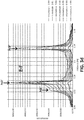
- Figure 3b , 3c , and 3d shows the strain signals obtained from each section (A-B, C-D, E-F) of the optical fiber sensor (3) when different levels of loads (1KN to 7 KN) are transversely applied to the direction followed by the optical fiber sensor (3).
- each section (A-B, C-D, E-F) of the optical fiber sensor (3) detects one transition (Pd1, Pd2; Pd1', Pd2'; Pd1", Pd2") in each one of the both extremes of the artificial defect (6), and a third transition (Pd3; Pd3'; Pd3") corresponding to the second groove.
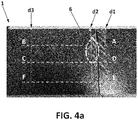
- Figure 4a shows a top view of the composite structure (1) similar to the view shown in Figure 3a in which the detected damage (6) has also been marked.
- one damage specifically a disbond, is detected when a load of 8KN is transversely applied to the composite part (2).
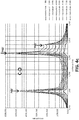
- Figure 4b shows the strain signals obtained from the section A-B of the optical fiber sensor (3) when different levels of loads (1KN to 8 KN) are transversely applied to the direction followed by the optical fiber sensor (3).
- the peak (Pd2) is shifted from the reference signal (consisting of the strain signal obtained when no load or a low load is transversely applied to the composite part (2)), which indicates that a damage (6) has been identified close to d2.
- Figures 4c and 4d show that although increasing levels of loads are applied to the composite part (2), no damage is detected, since no peak (Pd1', Pd2', Pd3'; Pd1", Pd2", Pd3") of the strain signals is displaced with respect to their reference signals.
- Figure 5a shows a top view of the composite structure (1) similar to the view shown in Figure 4a in which the detected damage (6) has grown when a load of 8,5KN has been transversely applied to the composite part (2).
- Figure 5b , 5c and 5d show the strain signals obtained from each of the sections A-B, C-D, E-F of the optical fiber sensor (3) when different levels of loads (1KN to 8,5 KN) are transversely applied to the direction followed by the optical fiber sensor (3).
- the peaks Pd2, Pd2' and Pd2" are shifted from their respective reference signals. This indicates that a damage (6) has been identified close to d2 and in the three sections, i.e. extending along the width of the part (2) as marked in Figure 5a .
- Figure 6a shows a top view of the composite structure (1) similar to the view shown in Figure 5a in which the first detected damage (6) has grown close to the section E-F and a new second damage (6) has appeared when a load of 9KN has been transversely applied to the composite part (2).
- Figures 6b and 6c show similar strain signals as obtained when a load of 8,5 KN is transversely applied to the direction followed by the optical fiber sensor (3). However, the peak Pd2" is shifted to a greater extent from its reference signal. This indicates that the first damage (6) has just grown in the section E-F.
- Figures 6b , 6c and 6d show that peaks Pd3, Pd3' and Pd3" are shifted from their respective reference signals. This indicates that a new damage (6) has been identified close to d3 and extending along the entire width of the part (2) as marked in Figure 6a .
- Figure 7a shows a top view of the composite structure (1) similar to the view shown in Figure 6a in which the first detected damage (6) has grown towards the second detected damage (6) when a load of 9,5KN has been transversely applied to the composite part (2).
- Figures 7b , 7c and 7d show that peaks Pd2, Pd2' and Pd2" are shifted to a greater extent from their respective reference signals, and towards the direction of d3, as marked in Figure 7a .
- Figure 8a shows a top view of the composite structure (1) similar to the view shown in Figure 7a in which both the first detected damage (6) has grown towards the second detected damage (6), and the second detected damage (6) has grown towards the first detected damage (6), when a load of 10KN has been transversely applied to the composite part (2).
- Figures 8b , 8c and 8d show that peaks Pd2, Pd2' and Pd2" are shifted even to a greater extent from their respective reference signals, and towards the direction of d3, as marked in Figure 8a .
- Figures 8b and 8d show that peaks Pd3 and Pd3" are shifted to a greater extent from their respective reference signals, and towards the direction of d2, as marked in Figure 8a .
- the optical fiber sensor (3) is embedded in the adhesive line (6).
- the optical fiber sensor (3) can be bonded to a surface of the composite part (2) or embedded between the layers of the composite part (2).
- Axial strain parameters can be represented by different types of graphs.
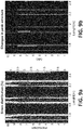
- Figure 9a and 9b shows a color-based graph related to the index of damage, where dark color means high probability of damage, medium dark color that the damage is not yet reached but it is closer (because of a high level of strain), and light color that no damage is foreseen.
- Figure 9a represents the deviation percentage of each peak of each strain signals obtained for the different levels of transversely applied loads (1KN to 10 KN) in the composite structure (1) shown in Figures 2-8 .
- Figure 9b represents the peak deviation values (in mm) of each one of the strain signals obtained for the different levels of transversely applied loads (1KN to 10 KN) in the composite structure (1) shown in Figures 2-8 .
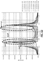
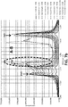
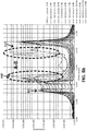
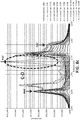
- Figure 10-13 shows the strain signal of a damaged composite part (drawing A), and the reference signal associated to the same composite part when it is undamaged (drawing B), when different levels of force of 4 KN, 5KN, 6KN, and 7KN is transversely applied to said part.
Landscapes
- Physics & Mathematics (AREA)
- General Physics & Mathematics (AREA)
- Engineering & Computer Science (AREA)
- Aviation & Aerospace Engineering (AREA)
- Chemical & Material Sciences (AREA)
- Analytical Chemistry (AREA)
- Length Measuring Devices By Optical Means (AREA)
- Optical Transform (AREA)
Abstract
The invention refers to a composite structure (1) with damage location capability that comprises a composite part (2) having an area to be monitored, an optical fiber sensor (3), and a processing data unit (4) adapted to: obtain optical parameters, convert these optical parameters into axial strain parameters, form a strain signal, identify a target area (5) in the composite part from each peak of the strain signal that surpasses a first value with respect to a reference signal associated to an undamaged composite part, identify a damage in the target area (5) from each displacement of each peak of the strain signal that surpasses a second value with respect to a reference signal associated to an undamaged composite part, and obtain the location of the damage from the location of the displaced peak. The invention further refers to a method for manufacturing a composite structure with damage location capability.

Description
- The present invention refers to a composite structure adapted to identify and localize a damage, such as a disbond or delamination occurred in a composite part.
- One object of the present invention is to provide a composite structure capable of performing an immediate detection and an accurate location of a damage present in a composite part. It is also an object of the invention to characterize the detected damage in order to be able of performing a diagnostic of the damage.
- Another object of the invention is to provide a composite structure capable of lowering the downtime caused by the current inspection of composite parts, and minimizing the need of such inspections, which usually involve unwanted costs and workload.
- The invention also refers to a method for manufacturing a composite structure with damage location capability.
- Another object of the invention is to provide a composite structure that is compatible with the manufacturing conditions of composite parts to easy the adaptations required in these composite parts.
- Nowadays, in-service inspections of composite parts are principally carried out by classical Non Destructive Inspections (NDI), and typically, by manual ultrasound pulse echo.
- Conventional inspections take place according to scheduled and/or unscheduled inspection programs. These inspections require access to the inspection area, availability of inspection systems, qualified inspectors, working time for the inspection, reporting and assessment of the results, and downtime of the equipment in which the composite part is integrated. All of these requirements involve substantial costs, and also an unpredictable availability of resources.
- Within the field of structural health monitoring of composite structures, optical fiber sensors are increasingly advancing with regard to other conventional instruments, becoming one of the best solution for some applications.
- Within the family of optical fiber sensors, discrete fiber Bragg grating sensors and distributed sensing fiber consisting of conventional optical fiber with backscattering reflection can be highly used due to their great potential.
- These technologies are being developed for measuring and monitoring structural deformations in different types of structures, such as composites used in the aeronautical industry.
- In aeronautical structures, traditional manufacturing processes for composites enable incorporating optical fibers within the material such that, after the polymerization of the composite, a unique material-sensor system is formed. This system constitutes a smart material with detecting capabilities potentially triggered by external excitations.
- Seeing this compatibility, it would therefore be desirable to provide technical means that based on optical fiber sensors leads to reduce the costs and disturbances derived by damaged composite structures.
- The present invention overcomes the above mentioned drawbacks by providing a composite structure with damage location capability, and a method for manufacturing a composite structure with damage location capability, which reduces the costs and disturbances derived by damaged structures.
- One aspect of the present invention refers to a composite structure with damage location capability that comprises at least one composite part having an area to be monitored, at least one optical fiber sensor in contact with at least the area to be monitored and deployed following a direction, and a processing data unit in communication with the at least one optical fiber sensor. The processing data unit is adapted to:
- obtain optical parameters associated to the area to be monitored from the optical fiber sensor,
- convert these optical parameters into axial strain parameters, said axial strain parameters representing the mechanical strain magnitude experienced by the composite part along an axial direction to the direction followed by the optical fiber sensor when a force transverse to the direction followed by the optical fiber sensor is applied,
- form a strain signal from the axial strain parameters,
- identify one target area in the composite part from each peak of the strain signal that surpasses a first established value with respect to a reference signal associated to an undamaged composite part,
- identify a damage in the target area from each displacement of each peak of the strain signal that surpasses a second established value with respect to the reference signal associated to the undamaged composite part,
- and obtain the location of the damage from the location of the displaced peak.
- Equipping a composite part with an optical fiber sensor and a processing data unit configured as mentioned above, provides a permanent damage inspection in said composite part. This on-board inspection allows an immediate detection of damage, avoiding the appearance of unexpected damages, and thus the downtime, workload and costs caused by the scheduled and unscheduled inspection of composite parts.
- In addition to identify damages, the invention provides precise location of the detected damages. This way, the invention offers valuable information for the diagnostic of the damage and for the repairing tasks.
- According to the invention, the processing data unit may be further adapted to obtain the size of the identified damage from the value of the distance that each peak of the strain signal has been displaced with respect to the location of said peak in a reference signal associated to the target area in an undamaged composite part.
- In addition, the processing data unit may be further adapted to obtain the residual strength of the composite part from the size of the identified damage.
- This way, the composite structure is adapted to shape or characterize the detected damage. Thus, the invention offers valuable information to make a diagnostic of the damage to know how severe is, and if so, if an immediate action to restore load capacity is required.
- The target area may comprise a transition area in the at least one composite part. Transition areas have different thickness and/or stiffness properties with respect to their adjacent areas. Usually, these different properties are caused by structural discontinuities in the composite part. Other target areas may include glued joints and/or structural damages (possibly caused by impacts received during the service of an aircraft).
- According to another preferred embodiment, the optical fiber sensor consists of multiplexed Bragg gratings or distributed sensing fiber based on the monitoring of the backscattering reflection.
- According to another preferred embodiment, the invention contemplates an aircraft that comprises a composite structure with damage location capability as describe above. The damage detection can be performed off-line, when the aircraft is on ground, and on-line, in a continuous process during flight operation, in function of the configuration of the used processing data unit.
- Another aspect of the invention refers to a method for manufacturing a composite structure with damage location capability comprising the steps of providing at least one composite part having an area to be monitored, providing at least one optical fiber sensor and deploying it following a direction to be in contact with at least the area to be monitored, and providing a processing data unit, in communication with the at least one optical fiber sensor, and configuring the processing data unit to:
- obtain optical parameters associated to the monitored area from the optical fiber sensor,
- convert these optical parameters into axial strain parameters, said axial strain parameters representing the mechanical strain magnitude experienced by the composite part along an axial direction to the direction followed by the optical fiber sensor when a force transverse to the direction followed by the optical fiber sensor is applied,
- form a strain signal from axial strain parameters,
- identify one target area in the composite part from each peak (Pi) of the strain signal that surpasses a first established value with respect to a reference signal associated to an undamaged composite part,
- identify a damage in the target area from each displacement of each peak (Pi) of the strain signal that surpasses a second established value with respect to the reference signal associated to the undamaged composite part,
- obtain the location of the damage from the location of the displaced peak.
- The method of the invention provides a composite structure equipped with a processing data unit and at least one optical fiber sensor in contact with a composite part to provide information (optical information) from which a strain profile can be obtained. The method can be applied and used with independence of the curing composite process: co-cured, co-bonded or secondary bonded.
- The method of the invention is compatible with the conventional manufacture of composites, sharing manufacturing conditions, trimming process and final assembly line. Thus, the method of the invention provides a simple and cost-effective way of producing composite structures with damage location.
- For a better comprehension of the invention, the following drawings are provided for illustrative and non-limiting purposes, wherein:
-
Figure 1a-1c show different views of an undamaged composite part that includes two transition areas. Drawing A shows a cross-sectional view, drawing B a detailed view of one transition area, and drawing C a top view of the composite part. -
Figure 2a-2b show different views of a composite structure according to an embodiment of the invention in which the composite part includes the two transition areas shown inFigure 1 and one artificial damage. Drawing A shows a cross-sectional view, and drawing B a top view of the composite structure where the location of the transitions have been highlighted. -
Figure 3a shows a top view of the composite structure shown inFigure 2 , where the artificial defect has been marked.Figure 3b shows the strain signals profile obtained from a first section of the optical fiber sensor (section A-B) when different levels of loads (1KN to 7 KN) are transversely applied to the direction followed by the optical fiber sensor.Figure 3c shows the strain signals profile obtained from a second section of the optical fiber sensor (section C-D) when different levels of loads (1KN to 7 KN) are transversely applied to the direction followed by the optical fiber sensor.Figure 3d shows the strain signals profile obtained from a third section of the optical fiber sensor (section E-F) when different levels of loads (1KN to 7 KN) are transversely applied to the direction followed by the optical fiber sensor. -
Figure 4a shows a top view of the composite structure shown inFigure 2 , where the artificial defect and the detected damage have been marked.Figures 4b -4d show the strain signals profile obtained from each one of the sections of the optical fiber sensor when different levels of loads (1KN to 8 KN) are transversely applied to the direction followed by the optical fiber sensor. -
Figure 5a shows a top view of the composite structure shown inFigure 2 , where the artificial defect and the detected damages have been marked.Figures 5b - 5d show the strain signals profile obtained from each one of the sections of the optical fiber sensor when different levels of loads (1KN to 8,5 KN) are transversely applied to the direction followed by the optical fiber sensor. -
Figure 6a shows a top view of the composite structure shown inFigure 2 , where the artificial defect and the detected damages have been marked.Figures 6b - 6d show the strain signals profile obtained from each one of the sections of the optical fiber sensor when different levels of loads (1KN to 9 KN) are transversely applied to the direction followed by the optical fiber sensor. -
Figure 7a shows a top view of the composite structure shown inFigure 2 , where the artificial defect and the detected damages have been marked.Figures 7b - 7d show the strain signals profile obtained from each one of the sections of the optical fiber sensor when different levels of loads (1KN to 9,5 KN) are transversely applied to the direction followed by the optical fiber sensor. -
Figure 8a shows a top view of the composite structure shown inFigure 2 , where the artificial defect and the detected damages have been marked.Figures 8b - 8d show the strain signals profile obtained from each one of the sections of the optical fiber sensor when different levels of loads (1KN to 10 KN) are transversely applied to the direction followed by the optical fiber sensor. -
Figure 9a shows, in a color-based graph, the deviation percentage of each peak of each one of the strain signals obtained from different levels of transversely applied loads (1KN to 10 KN).Figure 9b shows, in a color-based graph, the peak deviation values (in mm) of each one of the strain signals obtained from different levels of transversely applied loads (1KN to 10 KN). -
Figure 10a shows both the strain signal of a damaged composite part and the reference signal corresponding to the undamaged part when a force of 4 KN is transversely applied to said part.Figure 10b shows the difference between both the strain signal and the reference signal. -
Figure 11a shows both the strain signal of a damaged composite part and the reference signal corresponding to the undamaged part when a force of 5 KN is transversely applied to said part.Figure 11b shows the difference between both the strain signal and the reference signal. -
Figure 12a shows both the strain signal of a damaged composite part and the reference signal corresponding to the undamaged part when a force of 6 KN is transversely applied to said part.Figure 12b shows the difference between both the strain signal and the reference signal. -
Figure 13a shows both the strain signal of a damaged composite part and the reference signal corresponding to the undamaged part when a force of 7 KN is transversely applied to said part.Figure 13b shows the difference between both the strain signal and the reference signal. -
Figures 1a-c shows different views of an undamaged composite part (10) that includes an upper layout (7), a lower layout (8), and an adhesive line (9) in between bonding the two layers (7, 8) together. As shown, the undamaged composite part (10) further includes two target areas (5) comprising transition areas. Transition areas have different thickness and/or stiffness properties caused by the inclusion of structural discontinuities with respect to their adjacent areas. Examples of transition areas are areas containing stringer run-outs. In the showed case, the transition areas correspond to a pair of grooves performed in the lower layout (8). -
Figures 2a-b shows a composite structure (1) according to an embodiment of the invention. The structure (1) comprises a composite part (2), an optical fiber sensor (3) to obtain measurements, and a processing data unit (4) connected to the optical fiber sensor (3) for processing said measurements. As shown in the cross-sectional view ofFigure 2a , the part (2) has the same configuration and transitions as the part shown inFigure 1 , besides to one (artificial) damage (6) to be detected. - As further shown in
Figure 2a , the optical fiber sensor (3) is embedded into the adhesive line (9) disposed between the layers (7, 8), and deployed along the longitudinal direction of the part (2). Further, as shown inFigure 2b , the optical fiber sensor (3) covers its width to provide more measurements in the transition areas. - The optical fiber sensor (3) is connected to the processing data unit (4), which, according to the invention, is adapted to obtain optical parameters; convert these optical parameters into strain parameters in an axial (parallel) direction to the direction followed by the optical fiber sensor (3) (major direction of the part (2)), wherein said axial strain parameters represents the mechanical strain magnitude experienced by the composite part (2) along an axial direction to the direction followed by the optical fiber sensor (3) when a force transverse to the direction followed by the optical fiber sensor (3) is applied; form a strain signal (S) from the axial strain parameters; identify one target area (5) (transition area) in the composite part (2) from each peak (Pi) of the strain signal (S) that surpasses a first established value with respect to a reference signal associated to an undamaged composite part, identify a damage (6) in the target area (5) (transition area) from each displacement of each peak (Pi) of the strain signal (S) that surpasses a second established value with respect to a reference signal associated to the undamaged composite part (10), and obtain the location of the damage from the location of the displaced peak.
-
Figure 3a shows a top view of the composite structure (1) shown inFigure 2 , where different sections (A-B, C-D, E-F) of the optical fiber sensor (3) and the location of the transitions (both extremes of the artificial defect (d1, d2), and groove (d3)) have been marked. -
Figure 3b ,3c , and3d shows the strain signals obtained from each section (A-B, C-D, E-F) of the optical fiber sensor (3) when different levels of loads (1KN to 7 KN) are transversely applied to the direction followed by the optical fiber sensor (3). As shown inFigures 3b ,3c ,3d , each section (A-B, C-D, E-F) of the optical fiber sensor (3) detects one transition (Pd1, Pd2; Pd1', Pd2'; Pd1", Pd2") in each one of the both extremes of the artificial defect (6), and a third transition (Pd3; Pd3'; Pd3") corresponding to the second groove. - As shown in
Figures 3b ,3c ,3d , although increasing levels of loads are applied to the composite part (2), from 1KN to 7 KN, no damage is detected since no peak (Pd1, Pd2, Pd3; Pd1', Pd2', Pd3'; Pd1", Pd2", Pd3") of the strain signals is displaced with respect to a reference signal associated to the transition area in an undamaged composite part (10). Said reference signal consists of the strain signal obtained when no load or a low load (for instance, a load of 1 KN) is transversely applied to the composite part (2). -
Figure 4a shows a top view of the composite structure (1) similar to the view shown inFigure 3a in which the detected damage (6) has also been marked. In this case, one damage, specifically a disbond, is detected when a load of 8KN is transversely applied to the composite part (2). -
Figure 4b shows the strain signals obtained from the section A-B of the optical fiber sensor (3) when different levels of loads (1KN to 8 KN) are transversely applied to the direction followed by the optical fiber sensor (3). As shown, the peak (Pd2) is shifted from the reference signal (consisting of the strain signal obtained when no load or a low load is transversely applied to the composite part (2)), which indicates that a damage (6) has been identified close to d2. - However,
Figures 4c and4d , show that although increasing levels of loads are applied to the composite part (2), no damage is detected, since no peak (Pd1', Pd2', Pd3'; Pd1", Pd2", Pd3") of the strain signals is displaced with respect to their reference signals. - Since the peaks Pd2' and Pd2" are no displaced, it can be said that the damage (6) is located close to d2 and close to the first section of the fiber A-B (not extending to the second C-D, neither to the third section E-F).
-
Figure 5a shows a top view of the composite structure (1) similar to the view shown inFigure 4a in which the detected damage (6) has grown when a load of 8,5KN has been transversely applied to the composite part (2). -
Figure 5b ,5c and5d show the strain signals obtained from each of the sections A-B, C-D, E-F of the optical fiber sensor (3) when different levels of loads (1KN to 8,5 KN) are transversely applied to the direction followed by the optical fiber sensor (3). As shown, the peaks Pd2, Pd2' and Pd2" are shifted from their respective reference signals. This indicates that a damage (6) has been identified close to d2 and in the three sections, i.e. extending along the width of the part (2) as marked inFigure 5a . -
Figure 6a shows a top view of the composite structure (1) similar to the view shown inFigure 5a in which the first detected damage (6) has grown close to the section E-F and a new second damage (6) has appeared when a load of 9KN has been transversely applied to the composite part (2). -
Figures 6b and6c show similar strain signals as obtained when a load of 8,5 KN is transversely applied to the direction followed by the optical fiber sensor (3). However, the peak Pd2" is shifted to a greater extent from its reference signal. This indicates that the first damage (6) has just grown in the section E-F. - In addition,
Figures 6b ,6c and6d show that peaks Pd3, Pd3' and Pd3" are shifted from their respective reference signals. This indicates that a new damage (6) has been identified close to d3 and extending along the entire width of the part (2) as marked inFigure 6a . -
Figure 7a shows a top view of the composite structure (1) similar to the view shown inFigure 6a in which the first detected damage (6) has grown towards the second detected damage (6) when a load of 9,5KN has been transversely applied to the composite part (2). -
Figures 7b ,7c and7d show that peaks Pd2, Pd2' and Pd2" are shifted to a greater extent from their respective reference signals, and towards the direction of d3, as marked inFigure 7a . -
Figure 8a shows a top view of the composite structure (1) similar to the view shown inFigure 7a in which both the first detected damage (6) has grown towards the second detected damage (6), and the second detected damage (6) has grown towards the first detected damage (6), when a load of 10KN has been transversely applied to the composite part (2). -
Figures 8b ,8c and8d show that peaks Pd2, Pd2' and Pd2" are shifted even to a greater extent from their respective reference signals, and towards the direction of d3, as marked inFigure 8a . - In addition,
Figures 8b and8d show that peaks Pd3 and Pd3" are shifted to a greater extent from their respective reference signals, and towards the direction of d2, as marked inFigure 8a . - In the showed
Figures 1-8 , the optical fiber sensor (3) is embedded in the adhesive line (6). Alternatively, the optical fiber sensor (3) can be bonded to a surface of the composite part (2) or embedded between the layers of the composite part (2). - Axial strain parameters can be represented by different types of graphs. For instance,
Figure 9a and 9b shows a color-based graph related to the index of damage, where dark color means high probability of damage, medium dark color that the damage is not yet reached but it is closer (because of a high level of strain), and light color that no damage is foreseen.Figure 9a represents the deviation percentage of each peak of each strain signals obtained for the different levels of transversely applied loads (1KN to 10 KN) in the composite structure (1) shown inFigures 2-8 .Figure 9b represents the peak deviation values (in mm) of each one of the strain signals obtained for the different levels of transversely applied loads (1KN to 10 KN) in the composite structure (1) shown inFigures 2-8 . - In another way of representing the information,
Figure 10-13 shows the strain signal of a damaged composite part (drawing A), and the reference signal associated to the same composite part when it is undamaged (drawing B), when different levels of force of 4 KN, 5KN, 6KN, and 7KN is transversely applied to said part.
Claims (15)
- A composite structure (1) with damage location capability, comprising:- at least one composite part (2) having an area to be monitored,- at least one optical fiber sensor (3) in contact with at least the area to be monitored and deployed following a direction, and- a processing data unit (4), in communication with the at least one optical fiber sensor (3), and adapted to:- obtain optical parameters associated to the area to be monitored from the at least one optical fiber sensor (3),- convert these optical parameters into axial strain parameters representing the mechanical strain magnitude experienced by the composite part (2) along an axial direction to the direction followed by the optical fiber sensor (3) when a force transverse to the direction followed by the optical fiber sensor (3) is applied,- form a strain signal (S) from axial strain parameters,- identify one target area (5) in the composite part (2) from each peak (Pi) of the strain signal (S) that surpasses a first established value with respect to a reference signal associated to an undamaged composite part,- identify a damage in the target area (5) from each displacement of each peak (Pi) of the strain signal (S) that surpasses a second established value with respect to the reference signal associated to the undamaged composite part,- obtain the location of the damage from the location of the displaced peak.
- A composite structure (1) with damage location capability, according to claim 1, wherein the processing data unit (4) is further adapted to obtain the size of the identified damage from the value of the distance that each peak of the strain signal has been displaced with respect to the location of said peak in a reference signal associated to the target area (5) in an undamaged composite part.
- A composite structure (1) with damage location capability, according to claim 2, wherein the processing data unit (4) is further adapted to obtain the residual strength of the composite part (2) from the size of the identified damage.
- A composite structure (1) with damage location capability, according to any of the preceding claims, wherein the optical fiber sensor (3) is bonded to a surface of the composite part (2).
- A composite structure (1) with damage location capability, according to any of the preceding claims, wherein the composite part (2) comprises at least two layers, and the optical fiber sensor (3) is embedded between said layers.
- A composite structure (1) with damage location capability, according to any of the preceding claims, wherein further comprises at least one adhesive line (9) joined to the composite part (2), and wherein the optical fiber sensor (3) is embedded in the at least one adhesive line (9).
- A composite structure (1) with damage location capability, according to any of the preceding claims, wherein the target area (5) comprises a transition area in the at least one composite part (2).
- An aircraft, comprising a composite structure (1) with damage location capability according to any of claims 1 to 7.
- A method for manufacturing a composite structure (1) with damage location capability, comprising the steps of:- providing at least one composite part (2) having an area to be monitored,- providing at least one optical fiber sensor (3), and deploying the at least one optical fiber sensor (3) to be in contact with at least the area to be monitored, and- providing a processing data unit (4), in communication with the at least one optical fiber sensor (3), and- adapting the processing data unit (4) to:- obtain optical parameters associated to the area to be monitored from the optical fiber sensor (3),- convert these optical parameters into axial strain parameters representing the mechanical strain magnitude experienced by the composite part (2) along an axial direction to the direction followed by the optical fiber sensor (3) when a force transverse to the direction followed by the optical fiber sensor (3) is applied,- form a strain signal (S) from axial strain parameters,- identify one target area (5) in the composite part (2) from each peak (Pi) of the strain signal (S) that surpasses a first established value with respect to a reference signal associated to an undamaged composite part,- identify a damage in the target area (5) from each displacement of each peak (Pi) of the strain signal (S) that surpasses a second established value with respect to a reference signal associated to an undamaged composite part,- obtain the location of the damage from the location of the displaced peak.
- A method for manufacturing a composite structure (1) with damage location capability, according to claim 9, wherein the processing data unit (4) is further adapted to obtain the size of the identified damage from the value of the distance that each peak of the strain signal has been displaced with respect to the location of said peak in a reference signal associated to the target area (5) in an undamaged composite part.
- A method for manufacturing a composite structure (1) with damage location capability, according to claim 10, wherein the processing data unit (4) is further adapted to obtain the residual strength of the composite part (2) from the size of the identified damage.
- A method for manufacturing a composite structure (1) with damage location capability, according to any of claims 9-11, wherein the optical fiber sensor (3) is bonded to a surface of the composite part (2).
- A method for manufacturing a composite structure (1) with damage location capability, according to any of claims 9-12, wherein the composite part (2) comprises at least two layers, and the optical fiber sensor (3) is embedded between said layers.
- A method for manufacturing a composite structure (1) with damage location capability, according to any of the claims 9-13, wherein further comprises at least one adhesive line (9) joined to the composite part (2), and wherein the optical fiber sensor (3) is embedded in the at least one adhesive line (9).
- A method for manufacturing a composite structure (1) with damage location capability, according to any of the claims 9-14, wherein the target area (5) comprises a transition area in the at least one composite part (2).
Priority Applications (1)
| Application Number | Priority Date | Filing Date | Title |
|---|---|---|---|
| EP18382280.8A EP3561473A1 (en) | 2018-04-25 | 2018-04-25 | A composite structure with damage location capability and method for manufacturing a composite structure with damage location capability |
Applications Claiming Priority (1)
| Application Number | Priority Date | Filing Date | Title |
|---|---|---|---|
| EP18382280.8A EP3561473A1 (en) | 2018-04-25 | 2018-04-25 | A composite structure with damage location capability and method for manufacturing a composite structure with damage location capability |
Publications (1)
| Publication Number | Publication Date |
|---|---|
| EP3561473A1 true EP3561473A1 (en) | 2019-10-30 |
Family
ID=62222537
Family Applications (1)
| Application Number | Title | Priority Date | Filing Date |
|---|---|---|---|
| EP18382280.8A Withdrawn EP3561473A1 (en) | 2018-04-25 | 2018-04-25 | A composite structure with damage location capability and method for manufacturing a composite structure with damage location capability |
Country Status (1)
| Country | Link |
|---|---|
| EP (1) | EP3561473A1 (en) |
Cited By (1)
| Publication number | Priority date | Publication date | Assignee | Title |
|---|---|---|---|---|
| CN113740425A (en) * | 2021-07-12 | 2021-12-03 | 北京航空航天大学 | Composite material laminated structure anisotropic damage identification method |
Citations (4)
| Publication number | Priority date | Publication date | Assignee | Title |
|---|---|---|---|---|
| EP1258760A2 (en) * | 2001-05-15 | 2002-11-20 | The Boeing Company | Embeddable fiber optic connector and associated method |
| US20130268471A1 (en) * | 2012-04-06 | 2013-10-10 | Gayan Chanaka Kahandawa Appuhamillage | Signal monitoring system and methods of operating same |
| EP2672234A1 (en) * | 2012-06-05 | 2013-12-11 | Airbus Operations GmbH | System and method for monitoring a component in production and/or in service |
| US20160116366A1 (en) * | 2014-10-28 | 2016-04-28 | Paulo Anchieta da Silva | Method and system for structural health monitoring with frequency synchronization |
-
2018
- 2018-04-25 EP EP18382280.8A patent/EP3561473A1/en not_active Withdrawn
Patent Citations (4)
| Publication number | Priority date | Publication date | Assignee | Title |
|---|---|---|---|---|
| EP1258760A2 (en) * | 2001-05-15 | 2002-11-20 | The Boeing Company | Embeddable fiber optic connector and associated method |
| US20130268471A1 (en) * | 2012-04-06 | 2013-10-10 | Gayan Chanaka Kahandawa Appuhamillage | Signal monitoring system and methods of operating same |
| EP2672234A1 (en) * | 2012-06-05 | 2013-12-11 | Airbus Operations GmbH | System and method for monitoring a component in production and/or in service |
| US20160116366A1 (en) * | 2014-10-28 | 2016-04-28 | Paulo Anchieta da Silva | Method and system for structural health monitoring with frequency synchronization |
Cited By (1)
| Publication number | Priority date | Publication date | Assignee | Title |
|---|---|---|---|---|
| CN113740425A (en) * | 2021-07-12 | 2021-12-03 | 北京航空航天大学 | Composite material laminated structure anisotropic damage identification method |
Similar Documents
| Publication | Publication Date | Title |
|---|---|---|
| EP2603430B1 (en) | Planking panel for a structural component, flow body comprising such a planking panel and device for monitoring material damage on such a planking panel | |
| EP0757238A1 (en) | Bonded joint analysis | |
| US8605263B2 (en) | Wind turbine blades strain measuring system during static tests | |
| Güemes | SHM technologies and applications in aircraft structures | |
| US12287303B2 (en) | Sacrificial sensor for determining damage to a part | |
| DE19522543A1 (en) | Piezoelectric measuring sensor system for roller bearings | |
| WO2024075077A1 (en) | Method for monitoring structural elements in composite | |
| CN1928539A (en) | Damage detection information smart coat with subsidiary damage feature | |
| US7303374B2 (en) | Disbond resistant composite joint and method of forming | |
| Rao et al. | Structural health monitoring (SHM) using strain gauges, PVDF film and fiber bragg grating (FBG) sensors: A comparative study | |
| US20060140532A1 (en) | Method to monitor structural damage occurrence and progression in monolithic composite structures using fibre Bragg grating sensors | |
| ITTO20080908A1 (en) | PROCEDURE FOR THE PROGNOSTICS OF A STRUCTURE UNDER LOADED LOADS. | |
| Dengg et al. | Damage monitoring of pinned hybrid composite–titanium joints using direct current electrical resistance measurement | |
| US20200309512A1 (en) | Evaluating method and evaluation system | |
| KR20060047105A (en) | Bridge bearing with buit-in optic fiber sensor for measurement | |
| Carboni et al. | Acoustic emission based monitoring of fatigue damage in CFRP-CFRP adhesive bonded joints | |
| GB2558899A (en) | Sensor | |
| Carboni et al. | Acoustic emission-based monitoring of fatigue damage in CFRP-CFRP adhesively bonded joints | |
| DE102007014160B4 (en) | System and method for monitoring the status of structural components | |
| EP3857213B1 (en) | Measuring method for determining a structural and wear state of a component | |
| Preisler et al. | Monitoring of fatigue damages in adhesively bonded joints | |
| Sundaram et al. | Structural health monitoring of composite structures-issues and challenges | |
| Janetzko-Preisler et al. | Integration and evaluation of a meander-shaped fibre-optical sensor in a GFRP leaf spring | |
| Takahashi et al. | Development of FBG-MFC hybrid SHM system for aircraft composite structures in collaboration study with Airbus | |
| Grefe et al. | Using distributed fibreoptic sensing to monitor repaired structures reinforced with steel‐patches |
Legal Events
| Date | Code | Title | Description |
|---|---|---|---|
| PUAI | Public reference made under article 153(3) epc to a published international application that has entered the european phase |
Free format text: ORIGINAL CODE: 0009012 |
|
| AK | Designated contracting states |
Kind code of ref document: A1 Designated state(s): AL AT BE BG CH CY CZ DE DK EE ES FI FR GB GR HR HU IE IS IT LI LT LU LV MC MK MT NL NO PL PT RO RS SE SI SK SM TR |
|
| AX | Request for extension of the european patent |
Extension state: BA ME |
|
| STAA | Information on the status of an ep patent application or granted ep patent |
Free format text: STATUS: THE APPLICATION IS DEEMED TO BE WITHDRAWN |
|
| 18D | Application deemed to be withdrawn |
Effective date: 20200603 |