EP3561450A1 - Stereo camera - Google Patents
Stereo camera Download PDFInfo
- Publication number
- EP3561450A1 EP3561450A1 EP17886573.9A EP17886573A EP3561450A1 EP 3561450 A1 EP3561450 A1 EP 3561450A1 EP 17886573 A EP17886573 A EP 17886573A EP 3561450 A1 EP3561450 A1 EP 3561450A1
- Authority
- EP
- European Patent Office
- Prior art keywords
- image
- unit
- parallax
- vertical offset
- stereo camera
- Prior art date
- Legal status (The legal status is an assumption and is not a legal conclusion. Google has not performed a legal analysis and makes no representation as to the accuracy of the status listed.)
- Pending
Links
Images




Classifications
-
- G—PHYSICS
- G01—MEASURING; TESTING
- G01C—MEASURING DISTANCES, LEVELS OR BEARINGS; SURVEYING; NAVIGATION; GYROSCOPIC INSTRUMENTS; PHOTOGRAMMETRY OR VIDEOGRAMMETRY
- G01C11/00—Photogrammetry or videogrammetry, e.g. stereogrammetry; Photographic surveying
- G01C11/04—Interpretation of pictures
- G01C11/06—Interpretation of pictures by comparison of two or more pictures of the same area
-
- H—ELECTRICITY
- H04—ELECTRIC COMMUNICATION TECHNIQUE
- H04N—PICTORIAL COMMUNICATION, e.g. TELEVISION
- H04N13/00—Stereoscopic video systems; Multi-view video systems; Details thereof
- H04N13/20—Image signal generators
- H04N13/204—Image signal generators using stereoscopic image cameras
- H04N13/239—Image signal generators using stereoscopic image cameras using two two-dimensional [2D] image sensors having a relative position equal to or related to the interocular distance
-
- G—PHYSICS
- G01—MEASURING; TESTING
- G01B—MEASURING LENGTH, THICKNESS OR SIMILAR LINEAR DIMENSIONS; MEASURING ANGLES; MEASURING AREAS; MEASURING IRREGULARITIES OF SURFACES OR CONTOURS
- G01B11/00—Measuring arrangements characterised by the use of optical techniques
-
- G—PHYSICS
- G03—PHOTOGRAPHY; CINEMATOGRAPHY; ANALOGOUS TECHNIQUES USING WAVES OTHER THAN OPTICAL WAVES; ELECTROGRAPHY; HOLOGRAPHY
- G03B—APPARATUS OR ARRANGEMENTS FOR TAKING PHOTOGRAPHS OR FOR PROJECTING OR VIEWING THEM; APPARATUS OR ARRANGEMENTS EMPLOYING ANALOGOUS TECHNIQUES USING WAVES OTHER THAN OPTICAL WAVES; ACCESSORIES THEREFOR
- G03B35/00—Stereoscopic photography
- G03B35/08—Stereoscopic photography by simultaneous recording
-
- G—PHYSICS
- G06—COMPUTING OR CALCULATING; COUNTING
- G06T—IMAGE DATA PROCESSING OR GENERATION, IN GENERAL
- G06T1/00—General purpose image data processing
-
- G—PHYSICS
- G06—COMPUTING OR CALCULATING; COUNTING
- G06T—IMAGE DATA PROCESSING OR GENERATION, IN GENERAL
- G06T5/00—Image enhancement or restoration
- G06T5/80—Geometric correction
-
- G—PHYSICS
- G06—COMPUTING OR CALCULATING; COUNTING
- G06T—IMAGE DATA PROCESSING OR GENERATION, IN GENERAL
- G06T7/00—Image analysis
-
- H—ELECTRICITY
- H04—ELECTRIC COMMUNICATION TECHNIQUE
- H04N—PICTORIAL COMMUNICATION, e.g. TELEVISION
- H04N13/00—Stereoscopic video systems; Multi-view video systems; Details thereof
- H04N13/10—Processing, recording or transmission of stereoscopic or multi-view image signals
- H04N13/106—Processing image signals
- H04N13/122—Improving the three-dimensional [3D] impression of stereoscopic images by modifying image signal contents, e.g. by filtering or adding monoscopic depth cues
-
- G—PHYSICS
- G06—COMPUTING OR CALCULATING; COUNTING
- G06T—IMAGE DATA PROCESSING OR GENERATION, IN GENERAL
- G06T2207/00—Indexing scheme for image analysis or image enhancement
- G06T2207/10—Image acquisition modality
- G06T2207/10004—Still image; Photographic image
- G06T2207/10012—Stereo images
Definitions
- the present invention relates to a stereo camera.
- the plurality of features are retrieved in the region of the predetermined range in the longitudinal direction in addition to the region on the image of the same height. Therefore, a processing load becomes large, it takes a long time until the offset of camera parameter in the longitudinal direction is corrected, the offset in the longitudinal direction between the right and left images becomes large in the period, and thus it is not possible to output a normal parallax image.
- An object of the present invention is to provide a stereo camera in which it is possible to improve the precision of correcting vertical offset between a first image captured by a first image-capture unit and a second image captured by a second image-capture unit.
- the invention includes a first image-capture unit which captures a first image, a second image-capture unit which captures a second image, a geometry correction unit which generates a plurality of third images having a different moving amount in a vertical direction from the second image, a parallax calculation unit which generates a plurality of parallax images from combinations of the first image and respective third images, a parallax image evaluation unit which calculates a reliable degree of each parallax image, and a vertical offset correction unit which calculates a maximum reliable degree and the moving amount corresponding to the maximum reliable degree on the basis of a correspondence relationship between the moving amount and the reliable degree, and sets the moving amount corresponding to the maximum reliable degree as a correction amount of a vertical offset.
- the stereo camera calculates a depth image from a plurality of camera images for example, and recognizes a subject on the images to calculate a distance up to the subject.
- an object of the embodiment of the invention is partially overlapped with the above-described object, and is to provide a stereo camera which corrects a large vertical offset between the right and left images generated by a mechanical offset such as a secular change, a thermal change, and an impulsive variation in a short time with high precision.
- FIG. 1 illustrates a configuration of the stereo camera of an embodiment of the invention.
- the embodiment of the invention includes an image-capture system unit 100a, an image-capture system unit 100b, a storage unit 110, an integrated-circuit computation unit 120 (logical circuit), a general computation unit 130, a screen voice output unit 140, and a control unit 150.
- the image-capture system unit 100a such as a camera includes an optical element unit 101a, and an image-capture element unit 102a.
- the optical element unit 101a such as a lens refracts light to form an image on the image-capture element unit 102a.
- the image-capture element unit 102a such as an image capturing element receives an image of the light refracted by the optical element unit 101a, and generates an image according to an intensity of the light.
- the image-capture system unit 100a (first image-capture unit) captures a first image.
- the image-capture system unit 100b such as a camera includes an optical element unit 101b, and an image-capture element unit 102b.
- the design values of focal distances of the image-capture system unit 100a and the image-capture system unit 100b are equal.
- the directions of the optical axes of the image-capture system unit 100a and the image-capture system unit 100b are almost the same.
- the optical element unit 101b such as a lens refracts light to form an image on the image-capture element unit 102b.
- the image-capture element unit 102b such as an image capturing element receives an image of the light refracted by the optical element unit 101b, and generates an image according to an intensity of the light.
- the image-capture system unit 100b (second image-capture unit) captures a second image.
- the image (first image) captured by the image-capture system unit 100a is an image which becomes a benchmark for creating a parallax image, and thus called a benchmark image.
- the image (second image) captured by the image-capture system unit 100b is an image from which a region matched to the region extracted from the benchmark image is retrieved when the parallax image is created, and called a reference image.
- the storage unit 110 configured by a memory includes a recognition-use-captured-image storage unit 111, a calibration-use-captured-image storage unit 112, a geometry-corrected-image storage unit 113, a parallax image storage unit 114, and a geometry correction information storage unit 115.
- the recognition-use-captured-image storage unit 111 such as a memory stores the images output from the image-capture system unit 100a and the image-capture system unit 100b. These images are subjected to the geometry correction by a geometry correction unit 125, and are finally used to perform the recognition of a vehicle or a pedestrian by a recognition unit 133.
- the calibration-use-captured-image storage unit 112 such as a memory stores the images output from the image-capture system unit 100a and the image-capture system unit 100b. These images are subjected to the geometry correction by the geometry correction unit 125, and are finally used to calculate the vertical offset between the benchmark image and the reference image by a vertical offset correction unit 132.
- the geometry-corrected-image storage unit 113 such as a memory stores the benchmark image (the geometry-corrected benchmark image) and the reference image (the geometry-corrected reference image) obtained by geometrically correcting the captured benchmark image (the benchmark image after capturing) and the captured reference image (the reference image after capturing).
- the parallax image storage unit 114 such as a memory stores the parallax image.
- the geometry correction information storage unit 115 such as a memory stores two-dimensional coordinates (geometry correction information) which is on the image (after capturing) having distortion and corresponds to pixels on the image having no distortion in the benchmark image and the reference image.
- the geometry correction information (mapping such as affine transformation) is used to correct a lens distortion and an optical axis offset of the benchmark image and the reference image after capturing by the geometry correction unit 125.
- the geometry correction information storage unit 115 storage unit
- the geometry correction unit 125 corrects an optical distortion of the benchmark image and the reference image using the geometry correction information.
- the geometry correction information storage unit 115 stores moving amounts in the vertical direction and the horizontal direction of the benchmark image and the reference image to correct offsets in the vertical direction and the horizontal direction generated by mechanical offsets such as a secular change, a thermal change, and an impulsive variation in the benchmark image and the reference image where the geometry correction is performed using the geometry correction information.
- the integrated-circuit computation unit 120 such as an field-programmable gate array (FPGA) or an application specific integrated circuit (ASIC) includes an input/output accommodation information storage unit 121, a geometry correction modification information storage unit 122, a synchronous signal generation unit 123, a benchmark image intake unit 124a, a reference image intake unit 124b, the geometry correction unit 125, and a parallax calculation unit 126.
- FPGA field-programmable gate array
- ASIC application specific integrated circuit
- the input/output accommodation information storage unit 121 such as a register stores information (address) of places in the storage unit 110 where the data input/output by the benchmark image intake unit 124a, the reference image intake unit 124b, the geometry correction unit 125, and the parallax calculation unit 126 is stored.
- initial values of the output destinations of the benchmark image intake unit 124a and the reference image intake unit 124b are set to the recognition-use-captured-image storage unit 111 of the storage unit 110.
- the initial value of an input place of the input of the geometry correction unit 125 is set to the recognition-use-captured-image storage unit 111 of the storage unit 110.
- the geometry correction modification information storage unit 122 such as a register stores the horizontal moving amount and the vertical moving amount of the benchmark image and the reference image to further move the image from the geometry correction information to the horizontal direction and the vertical direction when the geometry correction unit 125 performs the geometry correction on the image.
- the initial values of the horizontal moving amount and the vertical moving amount of the benchmark image and the reference image are zero.
- the synchronous signal generation unit 123 generates and transmits a synchronization signal.
- the benchmark image intake unit 124a sends the synchronization signal and exposure time information to the image-capture element unit 102a together with the synchronization signal of the synchronous signal generation unit 123, and acquires an image generated by the image-capture element unit 102a.
- the benchmark image intake unit 124a reads output place information of the image from the input/output accommodation information storage unit 121, and stores the image at the place of the storage unit 110.
- the reference image intake unit 124b sends the synchronization signal and the exposure time information to the image-capture element unit 102b together with the synchronization signal of the synchronous signal generation unit 123, and acquires the image generated by the image-capture element unit 102b.
- the reference image intake unit 124b reads output destination information of the image from the input/output accommodation information storage unit 121, and stores the image at the place of the storage unit 110.
- the geometry correction unit 125 reads input destination information of the image from the input/output accommodation information storage unit 121, and reads the benchmark image and the reference image from the place of the storage unit 110.
- the geometry correction unit 125 reads the geometry correction information from the geometry correction information storage unit 115, and reads the horizontal moving amount and the vertical moving amount of the benchmark image and the reference image from the geometry correction modification information storage unit 122.
- the geometry correction unit 125 adds the horizontal moving amount and the vertical moving amount of the benchmark image and the reference image together at the two-dimensional coordinates (geometry correction information) on the image having distortion which corresponds to each pixel on the image having no distortion in the benchmark image and the reference image (geometry correction information).
- the geometry correction unit 125 performs the geometry correction on the basis of the benchmark image and the reference image after capturing, and the added geometry correction information, and calculates an image having no distortion. In other words, the geometry correction unit 125 corrects the optical distortion of the benchmark image (first image) and the reference image (second image).
- the geometry correction unit 125 stores the geometry-corrected benchmark image and the geometry-corrected reference image in the geometry-corrected-image storage unit 113.
- the parallax calculation unit 126 reads the geometry-corrected benchmark image and the geometry-corrected reference image from the geometry-corrected-image storage unit 113, and retrieves a region at the same height on the reference image corresponding to a predetermined-size region (template image) extracted from the benchmark image.
- the parallax calculation unit 126 calculates a difference (that is, parallax) between the position of the region on the reference image matched with the template image and the position of the template image on the benchmark image.
- the parallax calculation unit 126 calculates the parallax with respect to the regions to calculate the parallax image.
- the parallax calculation unit 126 determines whether the parallax is valid or invalid on the basis of a coincidence between the regions (template image) on the benchmark image and the region on the reference image most matched to these regions.
- the parallax calculation unit 126 stores the parallax image in the parallax image storage unit 114.
- the general computation unit 130 configured by a CPU (central processing unit) includes a parallax image evaluation unit 131, the vertical offset correction unit 132, the recognition unit 133, and an automatic geometry calibration unit 134.
- the parallax image evaluation unit 131 counts the number of valid regions (the number of valid blocks) of the parallax image, and calculates an evaluation value of reliability of the parallax image when the reference image is shifted by a predetermined interval ⁇ Y in the vertical direction in a predetermined range (that is, when the geometry-corrected benchmark image and the geometry-corrected reference image are shifted by the predetermined interval ⁇ Y in the predetermined range).
- the vertical offset correction unit 132 obtains a vertical offset of the largest number of valid regions of the parallax image (that is, a vertical offset of the evaluation value pertaining to a largest reliability of the parallax image), and set the vertical offset as a correction amount ⁇ Yc of a vertical offset.
- the recognition unit 133 reads the parallax image from the parallax image storage unit 114, and calculates a distance from the stereo camera up to the subject in the optical axial direction of the image-capture system unit 100a and the image-capture system unit 100b on the basis of the parallax, a distance between focuses of the image-capture system unit 100a and the image-capture system unit 100b (base line length), the focal distances, and the size of one pixel.
- the recognition unit 133 calculates a distance to each region to calculate the depth image.
- the recognition unit 133 reads the geometry-corrected benchmark image from the geometry-corrected-image storage unit 113, recognizes the position of the subject on the benchmark image and the position of the subject on the benchmark image using the geometry-corrected benchmark image and the depth image, and calculates a three-dimensional relative position and a relative speed of the subject with respect to the stereo camera.
- the principal point of the image-capture system unit 100a is the origin point, the x coordinate in the right direction with respect to the image-capture system unit 100a, the y coordinate is in the lower direction, and the z coordinate in the optical axial direction.
- the recognition unit 133 calculates a time until confliction on the basis of the relative position and the relative speed of the stereo camera and the subject, and determines whether the confliction occurs within a predetermined time.
- the recognition unit 133 sends the relative position, the relative speed, a confliction determination result, and a confliction time between the stereo camera and the subject to the screen voice output unit 140 and the control unit 150.
- the automatic geometry calibration unit 134 reads the geometry-corrected benchmark image and the geometry-corrected reference image from the geometry-corrected-image storage unit 113, and the parallax image from the parallax image storage unit 114, calculates a horizontal moving amount ⁇ X2 and a vertical moving amount ⁇ Y2 of the benchmark image such that the optical axial position (vanishing point) on the geometry-corrected benchmark image becomes the design value on the basis of the information, and calculates a horizontal moving amount ⁇ X1 of the reference image such that the parallax at the optical axial position (vanishing point) on the geometry-corrected benchmark image becomes zero.
- the automatic geometry calibration unit 134 stores these results in the geometry correction information storage unit 115.
- the screen voice output unit 140 such as a monitor and a speaker displays the benchmark image, the parallax image, or the depth image in a screen.
- the screen voice output unit 140 displays a frame or a marker at the position of the subject. At this time, the color of the frame or the marker of the subject determined to come into conflict from the confliction determination result from the recognition unit 133 is changed to another color for the subject which does not come into conflict.
- the screen voice output unit 140 outputs a warning sound in a case where there is a subject determined to come into conflict from the confliction determination result from the recognition unit 133.
- the control unit 150 such as a CPU generates a control signal on the basis of the relative position, the relative speed, the confliction time, and the confliction determination result between the stereo camera and the subject, and outputs the signal to the outside of the stereo camera.
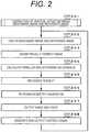
- FIGS. 2 and 3 An operation procedure of the embodiment of the stereo camera of the invention illustrated in FIG. 1 will be described using FIGS. 2 and 3 .
- Step 201 the geometry correction unit 125 geometrically corrects the reference image after capturing, and calculates the geometry-corrected reference image in which the reference image is shifted in the vertical direction by the predetermined interval ⁇ Y in the predetermined range.
- the geometry correction unit 125 generates a plurality of geometry-corrected reference images (third image) which have different moving amounts in the vertical direction from the reference image (second image).
- the parallax calculation unit 126 calculates the parallax image on the basis of the geometry-corrected benchmark image and the geometry-corrected reference image, and determines valid/invalid of each region of the parallax image. In other words, the parallax calculation unit 126 generates the plurality of parallax images from the combination of the benchmark image (first image) and each reference image (third image).
- the parallax image evaluation unit 131 calculates the number of valid regions (that is, the evaluation value pertaining to reliability of the parallax image) of the parallax image which is calculated from the geometry-corrected benchmark image and the geometry-corrected reference image obtained by shifting the reference image in the vertical direction by the predetermined interval ⁇ Y in the predetermined range. In other words, the parallax image evaluation unit 131 calculates a reliable degree of each parallax image. Further, the evaluation value (reliable degree) pertaining to reliability may be called an index indicating the number of valid parallax in each parallax image.
- the vertical offset correction unit 132 calculates the correction amount ⁇ Yc of the vertical offset on the basis of the number of valid regions (the evaluation value pertaining to reliability) of the parallax image calculated from the geometry-corrected benchmark image and the geometry-corrected reference image obtained by shifting the reference image in the vertical direction by the predetermined interval ⁇ Y in the predetermined range.
- the operation procedure of this step is illustrated in FIG. 3 . Further, the details will be described below.
- Step 202 the synchronous signal generation unit 123 generates the synchronization signal, and sends the signal to the benchmark image intake unit 124a and the reference image intake unit 124b.
- the benchmark image intake unit 124a sends the synchronization signal and the exposure time information to the image-capture element unit 102a immediately after the synchronization signal from the synchronous signal generation unit 123 is received.
- the image-capture element unit 102a receives the image of the light refracted by the optical element unit 101a by the exposure time immediately after the synchronization signal and the exposure time information from the benchmark image intake unit 124a is received, and generates and sends the image according to the intensity of the light to the benchmark image intake unit 124a.
- the benchmark image intake unit 124a receives the image from the image-capture element unit 102a, reads the output place information of the image from the input/output accommodation information storage unit 121, and stores the image at the place of the storage unit 110.
- the output destination of the benchmark image intake unit 124a in Step 304 is set to the recognition-use-captured-image storage unit 111. Therefore, the image is stored in the recognition-use-captured-image storage unit 111.
- the reference image intake unit 124b sends the synchronization signal and the exposure time information to the image-capture element unit 102b immediately after the synchronization signal from the synchronous signal generation unit 123 is received.
- the image-capture element unit 102b receives the image of the light refracted by the optical element unit 101b immediately after the synchronization signal and the exposure time information from the reference image intake unit 124b are received, generates the image according to the intensity of the light, and sends the image to the reference image intake unit 124b.
- the reference image intake unit 124b receives the image from the image-capture element unit 102b, reads the output place information of the image from the input/output accommodation information storage unit 121, and stores the image at the place of the storage unit 110.
- the output destination of the reference image intake unit 124b in Step 304 is set to the recognition-use-captured-image storage unit 111. Therefore, the image is stored in the recognition-use-captured-image storage unit 111.
- Step 203 the geometry correction unit 125 reads the input place of the image from the input/output accommodation information storage unit 121, and reads the benchmark image and the reference image after capturing at the place (the recognition-use-captured-image storage unit 111) of the storage unit 110.
- the geometry correction unit 125 reads the geometry correction information (mapping Fx) between the benchmark image and the reference image from the geometry correction information storage unit 115, and reads the horizontal moving amount and the vertical moving amount of the benchmark image and the reference image from the geometry correction modification information storage unit 122.
- the geometry correction unit 125 calculates the position (X1, Y1) of the benchmark image before capturing corresponding to the pixel (X2, Y2) of the geometry-corrected benchmark image on the basis of the coordinates (Fx(X2, Y2), Fy(X2, Y2)) on the image after capturing corresponding to each pixel on the geometry-corrected benchmark image, the horizontal moving amount ⁇ X2 of the benchmark image, and the vertical moving amount ⁇ Y2.
- X 1 Fx X 2 , Y 2 + ⁇ ⁇ X 2
- Y 1 Fy X 2 , Y 2 + ⁇ ⁇ Y 2
- the geometry correction unit 125 linearly interpolates luminance values of four pixels around the position (X1, Y1) of the benchmark image in a two-dimensional manner to calculate the luminance value of the pixel (X2, Y2) of the geometry-corrected benchmark image.
- the geometry correction unit 125 performs the above procedure on each pixel of the geometry-corrected benchmark image to calculate the luminance values of the geometry-corrected benchmark image.
- the geometry correction unit 125 performs the above procedure even on the reference image to calculate the luminance values of the geometry-corrected reference image.
- the geometry correction unit 125 stores the geometry-corrected benchmark image and the reference image in the geometry-corrected-image storage unit 113.
- Step 204 the parallax calculation unit 126 reads the geometry-corrected benchmark image and the reference image from the geometry-corrected-image storage unit 113. As illustrated in FIG. 4 , the parallax calculation unit 126 extracts an image 403 (template image) of the predetermined-size region of the geometry-corrected benchmark image 401. The parallax calculation unit 126 retrieves the image of the region showing the same subject as the template image 403 in the geometry-corrected reference image 402 by template matching.
- the parallax calculation unit 126 extracts an image 404 (retrieved image) of the predetermined-size region of the reference image 402 at the same height as the template image 403, and calculates a sum (SAD, Sum of Absolute Difference) of the absolute values of the differences between the luminance values of the template image 403 and the luminance values of the retrieved image 404.
- the parallax calculation unit 126 calculates the SAD with respect to the respective retrieved image 404 on the reference image 402 at the same height as the template image 403 to retrieve the retrieved image 405 having the smallest SAD value.
- the parallax calculation unit 126 performs an isometric linear fitting using the SAD of the retrieved image 405 and the SAD of the retrieved images of adjacent right one pixel and left one pixel from the retrieved image 405, and calculates a subpixel of the retrieved image 405 on the reference image which is most matched to the template image 403.
- the parallax calculation unit 126 adds the subpixel to the difference of the positions of the template image 403 and the retrieved image 405 to calculate the parallax of the template image 403 on the geometry-corrected benchmark image 401.
- the parallax calculation unit 126 determines whether the parallax is valid or invalid by the following two determination methods. In a case where it is determined that a minimum value of the obtained SAD is equal to or more than a threshold using the retrieved image 404 on the reference image 402 at the same height as the template image 403, the parallax calculation unit 126 determines that the template 403 and the retrieved image 405 are not matched and the parallax of the region is invalid. In a case where the minimum value of the SAD is less than the threshold, it is determined that the parallax is valid.
- the parallax calculation unit 126 calculates the difference (a slope of the SAD) between the adjacent SAD and the SAD in the SAD 501 indicating a coincidence of the pattern. Places 502 to 504 where the value of the difference is changed from negative to positive are calculated. The place 502 where the SAD is smallest and the place 503 of the second largest SAD are calculated. In a case where the difference of the SADs is less than the threshold, there is a possibility that there is a pattern similar to the template image and mismatching occurs. Therefore, it is determined that the parallax of the region is invalid. If not, it is determined that the parallax is valid.
- the parallax is determined as valid. In a case where a region determined as valid by both the determination methods is determined as valid. In a case where a region determined as invalid by any one of the methods is determined as invalid.
- the parallax calculation unit 126 calculates a similarly between the template image 403 of the benchmark image and the retrieved image 404 of the reference image with respect to a plurality of combinations of the retrieved image 404 (region) of the reference image (third image) at the same height as the template image 403 (region) of the benchmark image (first image).
- the parallax is calculated from the template image 403 of the benchmark image and the retrieved image 404 of the reference image of which the similarity is maximized. In a case where the maximum similarity is less than a first threshold, the parallax calculation unit 126 determines that the parallax is invalid.
- the parallax calculation unit 126 determines that the parallax is invalid. In a case where a maximum similarity is equal to or more than the first threshold, and there is only one maximum value of the similarity, the parallax calculation unit 126 determines that the parallax is valid. In a case where the maximum similarity is equal to or more than the first threshold, there are two or more maximum values of the similarity, and the difference between the largest maximum value and the second largest maximum value is equal to or more than the second threshold, the parallax calculation unit 126 determines that the parallax is valid. With this configuration, it is possible to determine whether the parallax is valid.
- Such a process is performed on all the regions on the geometry-corrected benchmark image to calculate the entire parallax of the benchmark image 401.
- the parallax image calculated as described above is stored in the parallax image storage unit 114.
- Step 205 the recognition unit 133 reads the parallax image from the parallax image storage unit 114, and the geometry-corrected image (the geometry-corrected benchmark image and the reference image) from the geometry-corrected-image storage unit 113.
- the recognition unit 133 calculates a distance L to the stereo camera in the region on the parallax image in the optical axial direction using Equation (3).
- f represents a design value of the focal distance of the image-capture system unit 100a and the image-capture system unit 100b
- B represents a distance (base line length) between the principal points of the image-capture system unit 100a and the image-capture system unit 100b
- d represents parallax
- c represents a pixel pitch of the image-capture element unit 102a and the image-capture element unit 102b.
- the recognition unit 133 performs the process on all the regions of the parallax image, and calculates a distance of the stereo camera in the entire parallax image in the optical axial direction to create the depth image.
- the recognition unit 133 calculates a position of the vanishing point on the benchmark image, determines the subject such as an automobile and a pedestrian, calculates the relative position and the relative speed of the subject with respect to the stereo camera, and determines a confliction between the subject and the stereo camera.
- the recognition unit 133 calculates the position of the vanishing point on the benchmark image in the following procedure.
- White lines on both sides at the boundary of the lane on the benchmark image are detected to calculate the slope of the white line on the benchmark image. If the white lines on both sides are straight lines, a position on the benchmark image at a point where the withe lines on both sides cross each other is calculated from the calculated slope. That position is the position of the vanishing point.
- the recognition unit 133 detects the subject such as an automobile and a pedestrian in the following procedure.
- the recognition unit 133 obtains a region 1 in the depth image where pixels continuing at a distance within the predetermined range.
- the predetermined range a plurality of ranges which are overlapped by 2.5 m in a range of 5 m wide with 5 to 10 m, 7.5 to 12.5 m, and 10 to 15 m.
- the recognition unit 133 obtains lengths in the longitudinal and lateral directions on the benchmark image of each region 1 where the pixels continuing at a distance within the predetermined range.
- the recognition unit 133 divides a value obtained by multiplying the length, the distance, and the pixel pitch in the longitudinal direction on the benchmark image of each region 1 by the focal distance to calculate a three-dimensional length in the longitudinal direction of each region 1.
- the recognition unit 133 divides a value obtained by multiplying the length, the distance, and the pixel pitch in the lateral direction on the benchmark image of each region 1 by the focal distance to calculate a three-dimensional length in the lateral direction of each region 1.
- the recognition unit 133 approximately calculates a position Vg in the longitudinal direction on the benchmark image related to the ground surface of each region 1 using Equation (4).
- Vv represents a height at the vanishing point
- Hi represents an installation height of the stereo camera
- Lr represents an average distance of the region 1.
- Equation (4) is a calculation formula on the assumption that the optical axes of the image-capture system unit 100a and the image-capture system unit 100b are almost in the horizontal direction. [Equation 4]
- Vg Vv ⁇ f ⁇ Hi / Lr ⁇ c
- the recognition unit 133 determines that the subject of the region 1 is an automobile.
- the recognition unit 133 determines that the subject of the region 1 is a pedestrian. These processes are performed on all the regions 1. The recognition unit 133 determines whether the subject is an automobile or a pedestrian.
- the recognition unit 133 calculates the relative position and the relative speed of the subject with respect to the stereo camera.
- the recognition unit 133 calculates the relative position (Xo, Yo, Zo) of the subject with respect to the stereo camera using Equations (5) to (7) in the region 1 in which the subject is determined as an automobile or a pedestrian.
- (Uo, Vo) represents a position on the benchmark image related to the center of the region 1 in which the subject is determined as an automobile or a pedestrian.
- Xo Lr ⁇ c ⁇ Uo / f
- Yo H + Lr ⁇ c ⁇ Vo ⁇ Vv / f
- Zo Lr
- Steps 202 to 208 are repeatedly performed in a predetermined period.
- the difference between the positions on the benchmark image of the region 1 detected in Step 205 of the current and previous processes is within the threshold, the subjects are determined as the same.
- a value obtained by subtracting the relative position calculated in Step 205 of the previous process from the relative position of the subject with respect to the stereo camera calculated in the current process is divided by a time interval of a processing cycle of Steps 202 to 208 to calculate the relative speed (Vx, Vy, Vz) of the subject with respect to the stereo camera.
- the recognition unit 133 determines the confliction between the subject and the stereo camera in the following procedure. In a case where a relative speed Vz of the subject with respect to the stereo camera is equal to or more than 0, the recognition unit 133 determines that there is no conflict with the subject of the region 1 determined as an automobile or a pedestrian. In a case where the relative speed Vz of the subject with respect to the stereo camera is negative, the recognition unit 133 divides a relative position Zo of the subject with respect to the stereo camera calculated in the current process by an absolute value of the relative speed Vz of the subject with respect to the stereo camera, and calculates a time (confliction time) taken until the confliction.
- the recognition unit 133 adds a relative position Xo of the subject to the value obtained by multiplying the confliction time to a relative speed Vx of the subject with respect to the stereo camera to calculate the relative position Xo of the subject with respect to the stereo camera at the time of confliction. Then, in a case where the relative speed Vz of the subject with respect to the stereo camera is negative, the confliction time falls within the threshold, and an absolute value of the relative position Xo of the subject with respect to the stereo camera at the time of confliction falls within the threshold, the recognition unit 133 determines that there is confliction with the subject of the region 1 determined as an automobile or a pedestrian. In other cases, the recognition unit 133 determines that there is confliction.
- the recognition unit 133 sends positions of four corners on the benchmark image related to the region 1 determined as an automobile or a pedestrian, the relative position and the relative speed of the subject with respect to the stereo camera, the confliction determination result, and the confliction time to the screen voice output unit 140 and the control unit 150.
- Step 206 the automatic geometry calibration unit 134 reads the geometry-corrected benchmark image and the reference image from the geometry-corrected-image storage unit 113, and the parallax image from the parallax image storage unit 114.
- the automatic geometry calibration unit 134 detects the right and left white lines of the lane on the geometry-corrected benchmark image to calculate approximate straight lines of the right and left white lines.
- the automatic geometry calibration unit 134 calculates an intersecting position of the approximate straight lines of the right and left white lines.
- the automatic geometry calibration unit 134 sends these correction amounts to the geometry correction information storage unit 115 and the geometry correction modification information storage unit 122 as the horizontal moving amount ⁇ X2 and the vertical moving amount ⁇ Y2 of the benchmark image.
- the geometry correction information storage unit 115 and the geometry correction modification information storage unit 122 store the horizontal moving amount ⁇ X2 and the vertical moving amount ⁇ Y2 of the benchmark image.
- the automatic geometry calibration unit 134 similarly detects the right and left white lines of the lane on the geometry-corrected reference image to calculate approximate straight lines of the right and left white lines.
- the intersecting position of the approximate straight lines of the right and left white lines us calculated.
- the difference between the intersecting position and the design value of the position of the optical axis is calculated as the correction amounts in the horizontal direction of the reference image.
- These correction amounts are sent to the geometry correction information storage unit 115 and the geometry correction modification information storage unit 122 as the horizontal moving amount ⁇ X1 of the reference image.
- the geometry correction information storage unit 115 and the geometry correction modification information storage unit 122 store the horizontal moving amount ⁇ X1 of the reference image.
- Step 207 the screen voice output unit 140 receives the positions of four corners on the benchmark image related to the region 1 determined as an automobile or a pedestrian, the relative position and the relative speed of the subject with respect to the stereo camera, the confliction determination result, and the confliction time from the recognition unit 133.
- the screen voice output unit 140 reads the geometry-corrected benchmark image from the geometry-corrected-image storage unit 113.
- the benchmark image is displayed in a screen, and the region 1 determined as an automobile or a pedestrian is displayed with a frame.
- the screen voice output unit 140 changes the color of the frame of the region 1 of the subject of the confliction determination result indicating confliction into the color of the frame of the region 1 of the subject of the determination result indicating no confliction, and displays in the screen. In a case where the confliction determination result indicates confliction in the region 1, the screen voice output unit 140 outputs a warning sound.
- Step 208 the control unit 150 receives the positions of four corners on the benchmark image related to the region 1 determined as an automobile or a pedestrian, the relative position and the relative speed of the subject with respect to the stereo camera, the confliction determination result, and the confliction time from the recognition unit 133.
- the confliction determination result indicates confliction in the region 1 determined as an automobile or a pedestrian
- a control signal for avoiding the confliction is generated and output to the outside of the stereo camera.
- Step 301 the vertical offset correction unit 132 reads the vertical moving amounts of the benchmark image and the reference image from the geometry correction information storage unit 115.
- Step 302 the vertical offset correction unit 132 sets the output destinations of the benchmark image intake unit 124a and the reference image intake unit 124b of the input/output accommodation information storage unit 121 to the calibration-use-captured-image storage unit 112 of the storage unit 110.
- Step 303 the synchronous signal generation unit 123 generates the synchronization signal, and sends the signal to the benchmark image intake unit 124a and the reference image intake unit 124b.
- the benchmark image intake unit 124a sends the synchronization signal and the exposure time information to the image-capture element unit 102a immediately after the synchronization signal from the synchronous signal generation unit 123 is received.
- the image-capture element unit 102a receives the image of the light refracted by the optical element unit 101a by the exposure time immediately after the synchronization signal and the exposure time information from the benchmark image intake unit 124a is received, and generates and sends the image according to the intensity of the light to the benchmark image intake unit 124a.
- the benchmark image intake unit 124a receives the image from the image-capture element unit 102a, reads the output place information of the image from the input/output accommodation information storage unit 121, and stores the image at the place of the storage unit 110.
- the output destination of the benchmark image intake unit 124a in Step 302 is set to the calibration-use-captured-image storage unit 112. Therefore, the image is stored in the calibration-use-captured-image storage unit 112.
- the reference image intake unit 124b sends the synchronization signal and the exposure time information to the image-capture element unit 102b immediately after the synchronization signal from the synchronous signal generation unit 123 is received.
- the image-capture element unit 102b receives the image of the light refracted by the optical element unit 101b immediately after the synchronization signal and the exposure time information from the reference image intake unit 124b are received, generates the image according to the intensity of the light, and sends the image to the reference image intake unit 124b.
- the reference image intake unit 124b receives the image from the image-capture element unit 102b, reads the output place information of the image from the input/output accommodation information storage unit 121, and stores the image at the place of the storage unit 110.
- the output destination of the reference image intake unit 124b in Step 302 is set to the calibration-use-captured-image storage unit 112. Therefore, the image is stored in the calibration-use-captured-image storage unit 112.
- Step 304 the vertical offset correction unit 132 sets the output destinations of the benchmark image intake unit 124a and the reference image intake unit 124b of the input/output accommodation information storage unit 121 to the recognition-use-captured-image storage unit 111 of the storage unit 110.
- Step 305 the vertical offset correction unit 132 sets the input place of the geometry correction unit 125 of the input/output accommodation information storage unit 121 to the calibration-use-captured-image storage unit 112 of the storage unit 110.
- Step 307 with the similar operation to Step 203, the geometry correction unit 125 geometrically corrects the benchmark image and the reference image after capturing, and moves the reference image in the vertical direction by the predetermined interval ⁇ Y in the predetermined range.
- Step 308 the parallax calculation unit 126 performs the operation similar to Step 204.
- Step 309 the parallax image evaluation unit 131 counts the number of regions determined as valid in the parallax image.
- Step 310 in a case where the vertical moving amount of the reference image is all set for every predetermined interval ⁇ Y in the predetermined range, and Step 306 to Step 309 are performed, the process proceeds to Step 311. If not, the process proceeds to Step 306.
- Step 311 the vertical offset correction unit 132 sets the vertical moving amount ⁇ Y1 of the reference image read in Step 301 to the vertical moving amount ⁇ Y1 of the reference image of the geometry correction modification information storage unit 122, and sets the input place of the geometry correction unit 125 of the input/output accommodation information storage unit 121 to the recognition-use-captured-image storage unit 111 of the storage unit 110.
- Step 312 the vertical offset correction unit 132 sets the difference between the vertical moving amounts of the benchmark image and the reference image to the vertical offset of the benchmark image and the reference image.
- the vertical offset correction unit 132 calculates the quadratic approximation 603 from the vertical offset (the vertical offset of the maximum number of valid regions 602) at which the number of valid regions of the parallax image is maximum using the data of the number of valid regions of the predetermined range in the number of valid regions 601 indicating an evaluation value of reliability of the parallax image in the vertical offset.
- the value of the vertical offset where the quadratic approximation of the number of valid regions becomes a maximum value is calculated, and is set to the correction amount ⁇ Yc of the vertical offset.
- the evaluation value pertaining to reliability of the parallax image indicates a coincidence in the vertical direction between the benchmark image and the reference image.
- the vertical offset correction unit 132 calculates, on the basis of a correspondence relationship between the vertical offset (moving amount) and the evaluation value pertaining to reliability (reliable degree), the evaluation value pertaining to the maximum reliability and a vertical offset that corresponds to this evaluation value, and sets the vertical offset that corresponds to the evaluation value pertaining to the maximum reliability as the correction amount of the vertical offset. With this configuration, it is possible to calculate the correction amount of the vertical offset with precision.
- Step 313 in a case where the following conditions are all satisfied, the vertical offset between the benchmark image and the reference image calculated in Step 312 is determined as normal, and the process proceeds to Step 314. If not, the vertical offset calculated in Step 312 is determined as abnormal, and the process proceeds to Step 301.
- the first and second conditions (i) and (ii) it is checked whether a position in which the vertical offset between the benchmark image and the reference image is detected is within a predetermined range of the vertical offset.
- the third condition (iii) it is checked whether the calculation of the quadratic approximation is normal.
- the fourth condition (iv) it is checked whether there is a change in the number of valid regions of the parallax image, and the vertical offset of the maximum number of valid regions can be detected with precision.
- a value obtained by adding the correction amount ⁇ Yc of the vertical offset to the vertical moving amount of the reference image is stored as the vertical moving amount ⁇ Y1 of the reference image in the geometry correction modification information storage unit 122.
- the retrieving region is wide, and a processing time is taken.
- the geometry correction of an image and the creating process of the parallax image are performed in real time by the parallax calculation unit 126 and the geometry correction unit 125 of the integrated-circuit computation unit 120. Therefore, it is possible to correct the vertical offset of the geometry-corrected benchmark image and the reference image in a short time.
- the entire surface of the benchmark image and the reference image is used, so that the vertical offset can be detected with high precision. Therefore, immediately after the stereo camera is activated, it is possible to correct the vertical offset between the benchmark image and the reference image, output the parallax image normally, and operate the conflict preventing function can be operated normally.
- Steps 301 and 314 of the operation procedure of the embodiment of the stereo camera of the invention illustrated in FIG. 1 it is possible to calculate a command value of the vertical offset correction on the basis of an image size, a template image (region) size of the parallax calculation, a parallax image size, a retrieval width at the time of creating the parallax image, and the number of creating the parallax image.
- the command value is divided by the processing cycle (fclock) of a calculation device such as a CPU or an FPGA, the processing time can be calculated.
- FIG. 7 is a graph illustrating a relation between the processing cycle of the calculation device and the processing time of the vertical offset correction.
- the embodiment of the invention can be realized in that device.
- stereo camera of the invention is not limited to the embodiment described above, and various modifications can be made. In the following, modifications of the stereo camera of the invention will be described.
- Step 204 of the operation procedure ( FIG. 2 ) of the embodiment of the stereo camera of the invention illustrated in FIG. 1 while the parallax calculation unit 126 can calculate Zero-mean Sum of Absolute Differences (ZSAD), Sum of Squared Differences (SSD), Zero-mean Sum of Squared Differences (ZSSD), Normalized Cross Correlation (NCC), or Zero-mean Normalized Cross Correlation (ZNCC), retrieve a region on the reference image of the smallest SAD value to calculate the parallax instead of calculating the SAD value, retrieving a region on the reference image of which the SAD value is smallest, and calculating the parallax.
- ZSAD Zero-mean Sum of Absolute Differences
- SSD Sum of Squared Differences
- ZSSD Zero-mean Sum of Squared Differences
- NCC Normalized Cross Correlation
- ZNCC Zero-mean Normalized Cross Correlation
- the parallax image evaluation unit 131 can detect the road surface to calculate a reciprocal of a deviation (standard deviation) of the parallax in a predetermined region of the road surface, and detect the vertical offset between the benchmark image and the reference image using the reciprocal as the evaluation value pertaining to reliability of the parallax image instead of counting the number of valid regions of the parallax image. If the vertical offset between the benchmark image and the reference image becomes large, it is not possible to calculate the parallax with precision, and the characteristic that the value of the parallax deviates is used.
- FIGS. 8 to 10 illustrate the operation procedure of the embodiment of the stereo camera of the invention illustrated in FIG. 1 . Further, the explanation on the operation procedure of Steps 202 to 208 described already will be omitted.
- Step 801 in a case where a remainder obtained by dividing the number of frames of a correction period by the frame number is 1, the process proceeds to Step 802. If not, the process proceeds to Step 202.
- Step 802 the parallax image evaluation unit 131 calculates the evaluation value pertaining to reliability of the parallax image.
- the vertical offset correction unit 132 calculates and corrects the vertical offset between the benchmark image and the reference image on the basis of the evaluation value.
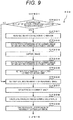
- FIGS. 9 and 10 illustrate the operation procedure of this step.
- Step 901 in the previous process of correcting the vertical offset between the benchmark image and the reference image, in a case where the correction amount ⁇ Yc of the vertical offset is calculated in Step 312, the process proceeds to Step 301. If not, the process proceeds to Step 306.
- the parallax image is created, and recognizes the subject such as a vehicle and a pedestrian. If a confliction to the subject is determined, a signal for preventing a confliction is output. In a process of one frame of correcting the vertical offset between the benchmark image and the reference image, one parallax image is created. If the process is performed by a predetermined number of parallax images used when the vertical offset is corrected, the correction amount ⁇ Yc of the vertical offset is calculated one time.
- Step 802 is performed one time for five frames.
- the correction amount ⁇ Yc of the vertical offset is calculated one time for 45 frames (5 frames x 9).
- the vertical offset between the benchmark image and the reference image is generated by the mechanical offset such as a secular change, a thermal change, and an impulsive variation .
- the correction amount ⁇ Yc of the vertical offset between the benchmark image and the reference image can always be calculated when the stereo camera is operating. Therefore, it is possible to correct the vertical offset between the benchmark image and the reference image caused by the mechanical offset such as a secular change, a thermal change, and an impulsive variation which is generated during the operation of the stereo camera.
- a command value of the calculating process of the evaluation value pertaining to reliability of one parallax image on the basis of an image size, the size of the template image (region) of calculating the parallax, and the size of the parallax image. If the command value is divided by the processing cycle (fclock) of the calculation device, the processing time can be calculated. In a case where the processing time for calculating the evaluation value pertaining to reliability of one parallax image is equal to or less than a sensing period, the embodiment of the invention can be realized by that device.
- the mapping showing the correspondence relationship before and after the geometry correction of the first image and the second image may include moving the second image in the vertical direction by the correction amount of the vertical offset.
- the geometry correction unit 125 corrects the optical distortion between the first image and the second image using the mapping, and also corrects the vertical offset generated by the mechanical offset such as a secular change, a thermal change, and an impulsive variation.
- the process of FIG. 3 may be performed when the stereo camera is activated. In addition, the process of FIG. 3 may be performed in a case where the ambient temperature of the stereo camera is changed by the threshold or more in a predetermined time. Further, the ambient temperature of the stereo camera is measured by a temperature sensor.
- the temperature sensor may be attached to the stereo camera, or may be attached to a vehicle.
- configurations and functions may be realized in hardware such as an integrated circuit.
- configurations and functions may be realized by software which analyzes and executes a program for executing each function by a processor (the general computation unit 130).
- the information of the program realizing functions, tables, and files may be secured in a recording device such as a memory, a hard disk, a Solid State Drive (SSD) or a recording medium such as an IC card, an SD card, and a DVD .
- SSD Solid State Drive
- embodiment of the invention may be configured as follows.
Landscapes
- Engineering & Computer Science (AREA)
- Physics & Mathematics (AREA)
- General Physics & Mathematics (AREA)
- Multimedia (AREA)
- Theoretical Computer Science (AREA)
- Signal Processing (AREA)
- Computer Vision & Pattern Recognition (AREA)
- Radar, Positioning & Navigation (AREA)
- Remote Sensing (AREA)
- Measurement Of Optical Distance (AREA)
- Image Analysis (AREA)
- Image Processing (AREA)
- Geometry (AREA)
- Length Measuring Devices By Optical Means (AREA)
- Stereoscopic And Panoramic Photography (AREA)
Abstract
Description
- The present invention relates to a stereo camera.
- There is known the related art in which a process of geometrically correcting two images is performed, features are extracted from the two images, and the same features on the two images are associated, and offsets of camera parameters are corrected on the basis of these features and a correspondence relationship of the images (for example, see PTL 1). Herein, in order to correct a camera parameter related to parallax, information on a distance between the feature and the camera or a distance between the features is used.
- PTL 1:
JP 2004-354257 A - In the related art disclosed in
PTL 1, in a case where there is a large offset in a longitudinal direction between the right and left images which is caused by a mechanical offset such as a secular change, a thermal change, and an impulsive variation when a stereo camera is activated, there is a need to retrieve a region of a predetermined range in the longitudinal direction instead of retrieving only a region on the image of the same height in order to retrieve a correspondence relationship of features of two images. In the retrieval of features, a matching method is used in which an index indicating a difference between patterns of two features is calculated. In addition, in order to correct the offset in the longitudinal direction between the right and left images with high precision, there is a need to obtain the correspondence relationship of a plurality of features. In this matching method, the plurality of features are retrieved in the region of the predetermined range in the longitudinal direction in addition to the region on the image of the same height. Therefore, a processing load becomes large, it takes a long time until the offset of camera parameter in the longitudinal direction is corrected, the offset in the longitudinal direction between the right and left images becomes large in the period, and thus it is not possible to output a normal parallax image. - An object of the present invention is to provide a stereo camera in which it is possible to improve the precision of correcting vertical offset between a first image captured by a first image-capture unit and a second image captured by a second image-capture unit.
- In order to achieve the above object, the invention includes a first image-capture unit which captures a first image, a second image-capture unit which captures a second image, a geometry correction unit which generates a plurality of third images having a different moving amount in a vertical direction from the second image, a parallax calculation unit which generates a plurality of parallax images from combinations of the first image and respective third images, a parallax image evaluation unit which calculates a reliable degree of each parallax image, and a vertical offset correction unit which calculates a maximum reliable degree and the moving amount corresponding to the maximum reliable degree on the basis of a correspondence relationship between the moving amount and the reliable degree, and sets the moving amount corresponding to the maximum reliable degree as a correction amount of a vertical offset.
- According to the invention, it is possible to improve the precision of correcting vertical offset between a first image captured by a first image-capture unit and a second image captured by a second image-capture unit. Objects, configurations, and effects besides the above description will be apparent through the explanation on the following embodiments.
-
-
FIG. 1 is a diagram illustrating a configuration of a stereo camera of an embodiment of the invention. -
FIG. 2 is a diagram illustrating an operation of the stereo camera. -
FIG. 3 is a diagram illustrating an operation of correcting a vertical offset between a benchmark image and a reference image of the stereo camera. -
FIG. 4 is a diagram illustrating the benchmark image and the reference image. -
FIG. 5 is a diagram illustrating a coincidence between a retrieval position and a pattern in parallax calculation. -
FIG. 6 is a diagram illustrating the vertical offset in the vertical offset correction between the benchmark image and the reference image and an evaluation value pertaining to reliability of a parallax image. -
FIG. 7 is a diagram illustrating a processing time of the vertical offset correction in a processing cycle of a calculation device. -
FIG. 8 is a diagram illustrating an operation of the stereo camera. -
FIG. 9 is a diagram illustrating an operation of correcting the vertical offset between the benchmark image and the reference image of the stereo camera. -
FIG. 10 is a diagram illustrating an operation of correcting the vertical offset between the benchmark image and the reference image of the stereo camera. - Hereinafter, a configuration and an operation of a stereo camera according to an embodiment of the invention will be described using the drawings. The stereo camera calculates a depth image from a plurality of camera images for example, and recognizes a subject on the images to calculate a distance up to the subject.
- Further, an object of the embodiment of the invention is partially overlapped with the above-described object, and is to provide a stereo camera which corrects a large vertical offset between the right and left images generated by a mechanical offset such as a secular change, a thermal change, and an impulsive variation in a short time with high precision.
-
FIG. 1 illustrates a configuration of the stereo camera of an embodiment of the invention. - The embodiment of the invention includes an image-capture system unit 100a, an image-capture system unit 100b, a
storage unit 110, an integrated-circuit computation unit 120 (logical circuit), ageneral computation unit 130, a screenvoice output unit 140, and a control unit 150. - The image-capture system unit 100a such as a camera includes an optical element unit 101a, and an image-capture element unit 102a.
- The optical element unit 101a such as a lens refracts light to form an image on the image-capture element unit 102a.
- The image-capture element unit 102a such as an image capturing element receives an image of the light refracted by the optical element unit 101a, and generates an image according to an intensity of the light.
- In other words, the image-capture system unit 100a (first image-capture unit) captures a first image.
- The image-capture system unit 100b such as a camera includes an optical element unit 101b, and an image-capture element unit 102b. In addition, the design values of focal distances of the image-capture system unit 100a and the image-capture system unit 100b are equal.
- The directions of the optical axes of the image-capture system unit 100a and the image-capture system unit 100b are almost the same.
- The optical element unit 101b such as a lens refracts light to form an image on the image-capture element unit 102b.
- The image-capture element unit 102b such as an image capturing element receives an image of the light refracted by the optical element unit 101b, and generates an image according to an intensity of the light.
- In other words, the image-capture system unit 100b (second image-capture unit) captures a second image.
- The image (first image) captured by the image-capture system unit 100a is an image which becomes a benchmark for creating a parallax image, and thus called a benchmark image. In addition, the image (second image) captured by the image-capture system unit 100b is an image from which a region matched to the region extracted from the benchmark image is retrieved when the parallax image is created, and called a reference image.
- The
storage unit 110 configured by a memory includes a recognition-use-captured-image storage unit 111, a calibration-use-captured-image storage unit 112, a geometry-corrected-image storage unit 113, a parallaximage storage unit 114, and a geometry correction information storage unit 115. - The recognition-use-captured-image storage unit 111 such as a memory stores the images output from the image-capture system unit 100a and the image-capture system unit 100b. These images are subjected to the geometry correction by a
geometry correction unit 125, and are finally used to perform the recognition of a vehicle or a pedestrian by arecognition unit 133. - The calibration-use-captured-image storage unit 112 such as a memory stores the images output from the image-capture system unit 100a and the image-capture system unit 100b. These images are subjected to the geometry correction by the
geometry correction unit 125, and are finally used to calculate the vertical offset between the benchmark image and the reference image by a verticaloffset correction unit 132. - The geometry-corrected-
image storage unit 113 such as a memory stores the benchmark image (the geometry-corrected benchmark image) and the reference image (the geometry-corrected reference image) obtained by geometrically correcting the captured benchmark image (the benchmark image after capturing) and the captured reference image (the reference image after capturing). - The parallax
image storage unit 114 such as a memory stores the parallax image. - The geometry correction information storage unit 115 such as a memory stores two-dimensional coordinates (geometry correction information) which is on the image (after capturing) having distortion and corresponds to pixels on the image having no distortion in the benchmark image and the reference image. The geometry correction information (mapping such as affine transformation) is used to correct a lens distortion and an optical axis offset of the benchmark image and the reference image after capturing by the
geometry correction unit 125. In other words, the geometry correction information storage unit 115 (storage unit) stores the geometry correction information (mapping) indicating a correspondence relationship before and after the geometry correction of the benchmark image (first image) and the reference image (second image). Thegeometry correction unit 125 corrects an optical distortion of the benchmark image and the reference image using the geometry correction information. - In addition, the geometry correction information storage unit 115 stores moving amounts in the vertical direction and the horizontal direction of the benchmark image and the reference image to correct offsets in the vertical direction and the horizontal direction generated by mechanical offsets such as a secular change, a thermal change, and an impulsive variation in the benchmark image and the reference image where the geometry correction is performed using the geometry correction information.
- The integrated-circuit computation unit 120 such as an field-programmable gate array (FPGA) or an application specific integrated circuit (ASIC) includes an input/output accommodation information storage unit 121, a geometry correction modification
information storage unit 122, a synchronoussignal generation unit 123, a benchmark image intake unit 124a, a reference image intake unit 124b, thegeometry correction unit 125, and aparallax calculation unit 126. - The input/output accommodation information storage unit 121 such as a register stores information (address) of places in the
storage unit 110 where the data input/output by the benchmark image intake unit 124a, the reference image intake unit 124b, thegeometry correction unit 125, and theparallax calculation unit 126 is stored. Herein, initial values of the output destinations of the benchmark image intake unit 124a and the reference image intake unit 124b are set to the recognition-use-captured-image storage unit 111 of thestorage unit 110. In addition, the initial value of an input place of the input of thegeometry correction unit 125 is set to the recognition-use-captured-image storage unit 111 of thestorage unit 110. - The geometry correction modification
information storage unit 122 such as a register stores the horizontal moving amount and the vertical moving amount of the benchmark image and the reference image to further move the image from the geometry correction information to the horizontal direction and the vertical direction when thegeometry correction unit 125 performs the geometry correction on the image. Herein, the initial values of the horizontal moving amount and the vertical moving amount of the benchmark image and the reference image are zero. - The synchronous
signal generation unit 123 generates and transmits a synchronization signal. - The benchmark image intake unit 124a sends the synchronization signal and exposure time information to the image-capture element unit 102a together with the synchronization signal of the synchronous
signal generation unit 123, and acquires an image generated by the image-capture element unit 102a. The benchmark image intake unit 124a reads output place information of the image from the input/output accommodation information storage unit 121, and stores the image at the place of thestorage unit 110. - The reference image intake unit 124b sends the synchronization signal and the exposure time information to the image-capture element unit 102b together with the synchronization signal of the synchronous
signal generation unit 123, and acquires the image generated by the image-capture element unit 102b. The reference image intake unit 124b reads output destination information of the image from the input/output accommodation information storage unit 121, and stores the image at the place of thestorage unit 110. - The
geometry correction unit 125 reads input destination information of the image from the input/output accommodation information storage unit 121, and reads the benchmark image and the reference image from the place of thestorage unit 110. Thegeometry correction unit 125 reads the geometry correction information from the geometry correction information storage unit 115, and reads the horizontal moving amount and the vertical moving amount of the benchmark image and the reference image from the geometry correction modificationinformation storage unit 122. Thegeometry correction unit 125 adds the horizontal moving amount and the vertical moving amount of the benchmark image and the reference image together at the two-dimensional coordinates (geometry correction information) on the image having distortion which corresponds to each pixel on the image having no distortion in the benchmark image and the reference image (geometry correction information). Thegeometry correction unit 125 performs the geometry correction on the basis of the benchmark image and the reference image after capturing, and the added geometry correction information, and calculates an image having no distortion. In other words, thegeometry correction unit 125 corrects the optical distortion of the benchmark image (first image) and the reference image (second image). Thegeometry correction unit 125 stores the geometry-corrected benchmark image and the geometry-corrected reference image in the geometry-corrected-image storage unit 113. - The
parallax calculation unit 126 reads the geometry-corrected benchmark image and the geometry-corrected reference image from the geometry-corrected-image storage unit 113, and retrieves a region at the same height on the reference image corresponding to a predetermined-size region (template image) extracted from the benchmark image. Theparallax calculation unit 126 calculates a difference (that is, parallax) between the position of the region on the reference image matched with the template image and the position of the template image on the benchmark image. Theparallax calculation unit 126 calculates the parallax with respect to the regions to calculate the parallax image. Next, theparallax calculation unit 126 determines whether the parallax is valid or invalid on the basis of a coincidence between the regions (template image) on the benchmark image and the region on the reference image most matched to these regions. Theparallax calculation unit 126 stores the parallax image in the parallaximage storage unit 114. - The
general computation unit 130 configured by a CPU (central processing unit) includes a parallax image evaluation unit 131, the vertical offsetcorrection unit 132, therecognition unit 133, and an automaticgeometry calibration unit 134. - The parallax image evaluation unit 131 counts the number of valid regions (the number of valid blocks) of the parallax image, and calculates an evaluation value of reliability of the parallax image when the reference image is shifted by a predetermined interval ΔY in the vertical direction in a predetermined range (that is, when the geometry-corrected benchmark image and the geometry-corrected reference image are shifted by the predetermined interval ΔY in the predetermined range).
- The vertical offset
correction unit 132 obtains a vertical offset of the largest number of valid regions of the parallax image (that is, a vertical offset of the evaluation value pertaining to a largest reliability of the parallax image), and set the vertical offset as a correction amount ΔYc of a vertical offset. - The
recognition unit 133 reads the parallax image from the parallaximage storage unit 114, and calculates a distance from the stereo camera up to the subject in the optical axial direction of the image-capture system unit 100a and the image-capture system unit 100b on the basis of the parallax, a distance between focuses of the image-capture system unit 100a and the image-capture system unit 100b (base line length), the focal distances, and the size of one pixel. Therecognition unit 133 calculates a distance to each region to calculate the depth image. Next, therecognition unit 133 reads the geometry-corrected benchmark image from the geometry-corrected-image storage unit 113, recognizes the position of the subject on the benchmark image and the position of the subject on the benchmark image using the geometry-corrected benchmark image and the depth image, and calculates a three-dimensional relative position and a relative speed of the subject with respect to the stereo camera. - Herein, in the three-dimensional relative coordinate system with respect to the stereo camera, the principal point of the image-capture system unit 100a is the origin point, the x coordinate in the right direction with respect to the image-capture system unit 100a, the y coordinate is in the lower direction, and the z coordinate in the optical axial direction. In addition, the
recognition unit 133 calculates a time until confliction on the basis of the relative position and the relative speed of the stereo camera and the subject, and determines whether the confliction occurs within a predetermined time. Therecognition unit 133 sends the relative position, the relative speed, a confliction determination result, and a confliction time between the stereo camera and the subject to the screenvoice output unit 140 and the control unit 150. - The automatic
geometry calibration unit 134 reads the geometry-corrected benchmark image and the geometry-corrected reference image from the geometry-corrected-image storage unit 113, and the parallax image from the parallaximage storage unit 114, calculates a horizontal moving amount ΔX2 and a vertical moving amount ΔY2 of the benchmark image such that the optical axial position (vanishing point) on the geometry-corrected benchmark image becomes the design value on the basis of the information, and calculates a horizontal moving amount ΔX1 of the reference image such that the parallax at the optical axial position (vanishing point) on the geometry-corrected benchmark image becomes zero. The automaticgeometry calibration unit 134 stores these results in the geometry correction information storage unit 115. - The screen
voice output unit 140 such as a monitor and a speaker displays the benchmark image, the parallax image, or the depth image in a screen. In addition, the screenvoice output unit 140 displays a frame or a marker at the position of the subject. At this time, the color of the frame or the marker of the subject determined to come into conflict from the confliction determination result from therecognition unit 133 is changed to another color for the subject which does not come into conflict. The screenvoice output unit 140 outputs a warning sound in a case where there is a subject determined to come into conflict from the confliction determination result from therecognition unit 133. - The control unit 150 such as a CPU generates a control signal on the basis of the relative position, the relative speed, the confliction time, and the confliction determination result between the stereo camera and the subject, and outputs the signal to the outside of the stereo camera.
- An operation procedure of the embodiment of the stereo camera of the invention illustrated in
FIG. 1 will be described usingFIGS. 2 and3 . - Step 201: the
geometry correction unit 125 geometrically corrects the reference image after capturing, and calculates the geometry-corrected reference image in which the reference image is shifted in the vertical direction by the predetermined interval ΔY in the predetermined range. In other words, thegeometry correction unit 125 generates a plurality of geometry-corrected reference images (third image) which have different moving amounts in the vertical direction from the reference image (second image). - The
parallax calculation unit 126 calculates the parallax image on the basis of the geometry-corrected benchmark image and the geometry-corrected reference image, and determines valid/invalid of each region of the parallax image. In other words, theparallax calculation unit 126 generates the plurality of parallax images from the combination of the benchmark image (first image) and each reference image (third image). - The parallax image evaluation unit 131 calculates the number of valid regions (that is, the evaluation value pertaining to reliability of the parallax image) of the parallax image which is calculated from the geometry-corrected benchmark image and the geometry-corrected reference image obtained by shifting the reference image in the vertical direction by the predetermined interval ΔY in the predetermined range. In other words, the parallax image evaluation unit 131 calculates a reliable degree of each parallax image. Further, the evaluation value (reliable degree) pertaining to reliability may be called an index indicating the number of valid parallax in each parallax image.
- The vertical offset
correction unit 132 calculates the correction amount ΔYc of the vertical offset on the basis of the number of valid regions (the evaluation value pertaining to reliability) of the parallax image calculated from the geometry-corrected benchmark image and the geometry-corrected reference image obtained by shifting the reference image in the vertical direction by the predetermined interval ΔY in the predetermined range. The operation procedure of this step is illustrated inFIG. 3 . Further, the details will be described below. - Step 202: the synchronous
signal generation unit 123 generates the synchronization signal, and sends the signal to the benchmark image intake unit 124a and the reference image intake unit 124b. The benchmark image intake unit 124a sends the synchronization signal and the exposure time information to the image-capture element unit 102a immediately after the synchronization signal from the synchronoussignal generation unit 123 is received. The image-capture element unit 102a receives the image of the light refracted by the optical element unit 101a by the exposure time immediately after the synchronization signal and the exposure time information from the benchmark image intake unit 124a is received, and generates and sends the image according to the intensity of the light to the benchmark image intake unit 124a. - The benchmark image intake unit 124a receives the image from the image-capture element unit 102a, reads the output place information of the image from the input/output accommodation information storage unit 121, and stores the image at the place of the
storage unit 110. Herein, the output destination of the benchmark image intake unit 124a in Step 304 is set to the recognition-use-captured-image storage unit 111. Therefore, the image is stored in the recognition-use-captured-image storage unit 111. - The reference image intake unit 124b sends the synchronization signal and the exposure time information to the image-capture element unit 102b immediately after the synchronization signal from the synchronous
signal generation unit 123 is received. The image-capture element unit 102b receives the image of the light refracted by the optical element unit 101b immediately after the synchronization signal and the exposure time information from the reference image intake unit 124b are received, generates the image according to the intensity of the light, and sends the image to the reference image intake unit 124b. The reference image intake unit 124b receives the image from the image-capture element unit 102b, reads the output place information of the image from the input/output accommodation information storage unit 121, and stores the image at the place of thestorage unit 110. Herein, the output destination of the reference image intake unit 124b in Step 304 is set to the recognition-use-captured-image storage unit 111. Therefore, the image is stored in the recognition-use-captured-image storage unit 111. - Step 203: the
geometry correction unit 125 reads the input place of the image from the input/output accommodation information storage unit 121, and reads the benchmark image and the reference image after capturing at the place (the recognition-use-captured-image storage unit 111) of thestorage unit 110. Thegeometry correction unit 125 reads the geometry correction information (mapping Fx) between the benchmark image and the reference image from the geometry correction information storage unit 115, and reads the horizontal moving amount and the vertical moving amount of the benchmark image and the reference image from the geometry correction modificationinformation storage unit 122. - Using Equation (1) and Equation (2), the
geometry correction unit 125 calculates the position (X1, Y1) of the benchmark image before capturing corresponding to the pixel (X2, Y2) of the geometry-corrected benchmark image on the basis of the coordinates (Fx(X2, Y2), Fy(X2, Y2)) on the image after capturing corresponding to each pixel on the geometry-corrected benchmark image, the horizontal moving amount ΔX2 of the benchmark image, and the vertical moving amount ΔY2.
[Equation 1]
[Equation 2]
- The
geometry correction unit 125 linearly interpolates luminance values of four pixels around the position (X1, Y1) of the benchmark image in a two-dimensional manner to calculate the luminance value of the pixel (X2, Y2) of the geometry-corrected benchmark image. Thegeometry correction unit 125 performs the above procedure on each pixel of the geometry-corrected benchmark image to calculate the luminance values of the geometry-corrected benchmark image. In addition, thegeometry correction unit 125 performs the above procedure even on the reference image to calculate the luminance values of the geometry-corrected reference image. Thegeometry correction unit 125 stores the geometry-corrected benchmark image and the reference image in the geometry-corrected-image storage unit 113. - Step 204: the
parallax calculation unit 126 reads the geometry-corrected benchmark image and the reference image from the geometry-corrected-image storage unit 113. As illustrated inFIG. 4 , theparallax calculation unit 126 extracts an image 403 (template image) of the predetermined-size region of the geometry-correctedbenchmark image 401. Theparallax calculation unit 126 retrieves the image of the region showing the same subject as thetemplate image 403 in the geometry-correctedreference image 402 by template matching. - The
parallax calculation unit 126 extracts an image 404 (retrieved image) of the predetermined-size region of thereference image 402 at the same height as thetemplate image 403, and calculates a sum (SAD, Sum of Absolute Difference) of the absolute values of the differences between the luminance values of thetemplate image 403 and the luminance values of the retrievedimage 404. Theparallax calculation unit 126 calculates the SAD with respect to the respective retrievedimage 404 on thereference image 402 at the same height as thetemplate image 403 to retrieve the retrieved image 405 having the smallest SAD value. Theparallax calculation unit 126 performs an isometric linear fitting using the SAD of the retrieved image 405 and the SAD of the retrieved images of adjacent right one pixel and left one pixel from the retrieved image 405, and calculates a subpixel of the retrieved image 405 on the reference image which is most matched to thetemplate image 403. Theparallax calculation unit 126 adds the subpixel to the difference of the positions of thetemplate image 403 and the retrieved image 405 to calculate the parallax of thetemplate image 403 on the geometry-correctedbenchmark image 401. - Next, the
parallax calculation unit 126 determines whether the parallax is valid or invalid by the following two determination methods. In a case where it is determined that a minimum value of the obtained SAD is equal to or more than a threshold using the retrievedimage 404 on thereference image 402 at the same height as thetemplate image 403, theparallax calculation unit 126 determines that thetemplate 403 and the retrieved image 405 are not matched and the parallax of the region is invalid. In a case where the minimum value of the SAD is less than the threshold, it is determined that the parallax is valid. - In addition, as illustrated in
FIG. 5 , theparallax calculation unit 126 calculates the difference (a slope of the SAD) between the adjacent SAD and the SAD in theSAD 501 indicating a coincidence of the pattern. Places 502 to 504 where the value of the difference is changed from negative to positive are calculated. The place 502 where the SAD is smallest and the place 503 of the second largest SAD are calculated. In a case where the difference of the SADs is less than the threshold, there is a possibility that there is a pattern similar to the template image and mismatching occurs. Therefore, it is determined that the parallax of the region is invalid. If not, it is determined that the parallax is valid. Herein, in a case where there is only one place where the difference of the adjacent SAD is changed from negative to positive, the parallax is determined as valid. In a case where a region determined as valid by both the determination methods is determined as valid. In a case where a region determined as invalid by any one of the methods is determined as invalid. - In other words, the
parallax calculation unit 126 calculates a similarly between thetemplate image 403 of the benchmark image and the retrievedimage 404 of the reference image with respect to a plurality of combinations of the retrieved image 404 (region) of the reference image (third image) at the same height as the template image 403 (region) of the benchmark image (first image). The parallax is calculated from thetemplate image 403 of the benchmark image and the retrievedimage 404 of the reference image of which the similarity is maximized. In a case where the maximum similarity is less than a first threshold, theparallax calculation unit 126 determines that the parallax is invalid. In a case where there are two or more maximum values of the similarity, and a difference between a largest maximum value and the second largest maximum value is less than a second threshold, theparallax calculation unit 126 determines that the parallax is invalid. In a case where a maximum similarity is equal to or more than the first threshold, and there is only one maximum value of the similarity, theparallax calculation unit 126 determines that the parallax is valid. In a case where the maximum similarity is equal to or more than the first threshold, there are two or more maximum values of the similarity, and the difference between the largest maximum value and the second largest maximum value is equal to or more than the second threshold, theparallax calculation unit 126 determines that the parallax is valid. With this configuration, it is possible to determine whether the parallax is valid. - Such a process is performed on all the regions on the geometry-corrected benchmark image to calculate the entire parallax of the
benchmark image 401. The parallax image calculated as described above is stored in the parallaximage storage unit 114. - Step 205: the
recognition unit 133 reads the parallax image from the parallaximage storage unit 114, and the geometry-corrected image (the geometry-corrected benchmark image and the reference image) from the geometry-corrected-image storage unit 113. - The
recognition unit 133 calculates a distance L to the stereo camera in the region on the parallax image in the optical axial direction using Equation (3). Herein, f represents a design value of the focal distance of the image-capture system unit 100a and the image-capture system unit 100b, B represents a distance (base line length) between the principal points of the image-capture system unit 100a and the image-capture system unit 100b, d represents parallax, and c represents a pixel pitch of the image-capture element unit 102a and the image-capture element unit 102b.
[Equation 3]
- The
recognition unit 133 performs the process on all the regions of the parallax image, and calculates a distance of the stereo camera in the entire parallax image in the optical axial direction to create the depth image. - Next, the
recognition unit 133 calculates a position of the vanishing point on the benchmark image, determines the subject such as an automobile and a pedestrian, calculates the relative position and the relative speed of the subject with respect to the stereo camera, and determines a confliction between the subject and the stereo camera. - First, the
recognition unit 133 calculates the position of the vanishing point on the benchmark image in the following procedure. White lines on both sides at the boundary of the lane on the benchmark image are detected to calculate the slope of the white line on the benchmark image. If the white lines on both sides are straight lines, a position on the benchmark image at a point where the withe lines on both sides cross each other is calculated from the calculated slope. That position is the position of the vanishing point. - Next, the
recognition unit 133 detects the subject such as an automobile and a pedestrian in the following procedure. - The
recognition unit 133 obtains aregion 1 in the depth image where pixels continuing at a distance within the predetermined range. As an example of the predetermined range, a plurality of ranges which are overlapped by 2.5 m in a range of 5 m wide with 5 to 10 m, 7.5 to 12.5 m, and 10 to 15 m. Therecognition unit 133 obtains lengths in the longitudinal and lateral directions on the benchmark image of eachregion 1 where the pixels continuing at a distance within the predetermined range. Therecognition unit 133 divides a value obtained by multiplying the length, the distance, and the pixel pitch in the longitudinal direction on the benchmark image of eachregion 1 by the focal distance to calculate a three-dimensional length in the longitudinal direction of eachregion 1. Similarly, therecognition unit 133 divides a value obtained by multiplying the length, the distance, and the pixel pitch in the lateral direction on the benchmark image of eachregion 1 by the focal distance to calculate a three-dimensional length in the lateral direction of eachregion 1. Therecognition unit 133 approximately calculates a position Vg in the longitudinal direction on the benchmark image related to the ground surface of eachregion 1 using Equation (4). Herein, Vv represents a height at the vanishing point, Hi represents an installation height of the stereo camera, and Lr represents an average distance of theregion 1. In addition, Equation (4) is a calculation formula on the assumption that the optical axes of the image-capture system unit 100a and the image-capture system unit 100b are almost in the horizontal direction.
[Equation 4]
- In a case where the three-dimensional lengths in the longitudinal and lateral directions of the
region 1 are within the predetermined range of an automobile, and the difference between a lower position in the longitudinal direction on the benchmark image of theregion 1 and the position in the longitudinal direction on the benchmark image of the ground surface of theregion 1 calculated by Equation (2) is within a threshold, therecognition unit 133 determines that the subject of theregion 1 is an automobile. Similarly, in a case where the three-dimensional lengths in the longitudinal and lateral directions of theregion 1 are within the predetermined range of a pedestrian, and the difference between a lower position in the longitudinal direction on the benchmark image of theregion 1 and the position in the longitudinal direction on the benchmark image of the ground surface of theregion 1 calculated by Equation (2) is within a threshold, therecognition unit 133 determines that the subject of theregion 1 is a pedestrian. These processes are performed on all theregions 1. Therecognition unit 133 determines whether the subject is an automobile or a pedestrian. - Next, the
recognition unit 133 calculates the relative position and the relative speed of the subject with respect to the stereo camera. Therecognition unit 133 calculates the relative position (Xo, Yo, Zo) of the subject with respect to the stereo camera using Equations (5) to (7) in theregion 1 in which the subject is determined as an automobile or a pedestrian. Herein, (Uo, Vo) represents a position on the benchmark image related to the center of theregion 1 in which the subject is determined as an automobile or a pedestrian.
[Equation 5]
[Equation 6]
[Equation 7]
- The processes of Steps 202 to 208 are repeatedly performed in a predetermined period. In a case where the difference between the positions on the benchmark image of the
region 1 detected in Step 205 of the current and previous processes is within the threshold, the subjects are determined as the same. A value obtained by subtracting the relative position calculated in Step 205 of the previous process from the relative position of the subject with respect to the stereo camera calculated in the current process is divided by a time interval of a processing cycle of Steps 202 to 208 to calculate the relative speed (Vx, Vy, Vz) of the subject with respect to the stereo camera. - Finally, the
recognition unit 133 determines the confliction between the subject and the stereo camera in the following procedure. In a case where a relative speed Vz of the subject with respect to the stereo camera is equal to or more than 0, therecognition unit 133 determines that there is no conflict with the subject of theregion 1 determined as an automobile or a pedestrian. In a case where the relative speed Vz of the subject with respect to the stereo camera is negative, therecognition unit 133 divides a relative position Zo of the subject with respect to the stereo camera calculated in the current process by an absolute value of the relative speed Vz of the subject with respect to the stereo camera, and calculates a time (confliction time) taken until the confliction. In addition, therecognition unit 133 adds a relative position Xo of the subject to the value obtained by multiplying the confliction time to a relative speed Vx of the subject with respect to the stereo camera to calculate the relative position Xo of the subject with respect to the stereo camera at the time of confliction. Then, in a case where the relative speed Vz of the subject with respect to the stereo camera is negative, the confliction time falls within the threshold, and an absolute value of the relative position Xo of the subject with respect to the stereo camera at the time of confliction falls within the threshold, therecognition unit 133 determines that there is confliction with the subject of theregion 1 determined as an automobile or a pedestrian. In other cases, therecognition unit 133 determines that there is confliction. Therecognition unit 133 sends positions of four corners on the benchmark image related to theregion 1 determined as an automobile or a pedestrian, the relative position and the relative speed of the subject with respect to the stereo camera, the confliction determination result, and the confliction time to the screenvoice output unit 140 and the control unit 150. - Step 206: the automatic
geometry calibration unit 134 reads the geometry-corrected benchmark image and the reference image from the geometry-corrected-image storage unit 113, and the parallax image from the parallaximage storage unit 114. The automaticgeometry calibration unit 134 detects the right and left white lines of the lane on the geometry-corrected benchmark image to calculate approximate straight lines of the right and left white lines. The automaticgeometry calibration unit 134 calculates an intersecting position of the approximate straight lines of the right and left white lines. On the assumption that the intersecting position is the vanishing point and matched to the position of the optical axis on the benchmark image, a difference between the intersecting position and the design value of the position of the optical axis is calculated as the correction amounts in the horizontal direction and the vertical direction of the benchmark image. The automaticgeometry calibration unit 134 sends these correction amounts to the geometry correction information storage unit 115 and the geometry correction modificationinformation storage unit 122 as the horizontal moving amount ΔX2 and the vertical moving amount ΔY2 of the benchmark image. The geometry correction information storage unit 115 and the geometry correction modificationinformation storage unit 122 store the horizontal moving amount ΔX2 and the vertical moving amount ΔY2 of the benchmark image. - With regard of the reference image, the automatic
geometry calibration unit 134 similarly detects the right and left white lines of the lane on the geometry-corrected reference image to calculate approximate straight lines of the right and left white lines. The intersecting position of the approximate straight lines of the right and left white lines us calculated. On the assumption that the intersecting position is the vanishing point and matched to the position of the optical axis on the reference image, the difference between the intersecting position and the design value of the position of the optical axis is calculated as the correction amounts in the horizontal direction of the reference image. These correction amounts are sent to the geometry correction information storage unit 115 and the geometry correction modificationinformation storage unit 122 as the horizontal moving amount ΔX1 of the reference image. The geometry correction information storage unit 115 and the geometry correction modificationinformation storage unit 122 store the horizontal moving amount ΔX1 of the reference image. - Step 207: the screen
voice output unit 140 receives the positions of four corners on the benchmark image related to theregion 1 determined as an automobile or a pedestrian, the relative position and the relative speed of the subject with respect to the stereo camera, the confliction determination result, and the confliction time from therecognition unit 133. The screenvoice output unit 140 reads the geometry-corrected benchmark image from the geometry-corrected-image storage unit 113. The benchmark image is displayed in a screen, and theregion 1 determined as an automobile or a pedestrian is displayed with a frame. In addition, the screenvoice output unit 140 changes the color of the frame of theregion 1 of the subject of the confliction determination result indicating confliction into the color of the frame of theregion 1 of the subject of the determination result indicating no confliction, and displays in the screen. In a case where the confliction determination result indicates confliction in theregion 1, the screenvoice output unit 140 outputs a warning sound. - Step 208: the control unit 150 receives the positions of four corners on the benchmark image related to the
region 1 determined as an automobile or a pedestrian, the relative position and the relative speed of the subject with respect to the stereo camera, the confliction determination result, and the confliction time from therecognition unit 133. In a case where the confliction determination result indicates confliction in theregion 1 determined as an automobile or a pedestrian, a control signal for avoiding the confliction is generated and output to the outside of the stereo camera. - An operation procedure of correcting the vertical offset between the benchmark image and the reference image of
Step 201 of the operation procedure of the embodiment of the stereo camera of the invention will be described usingFIG. 3 . - Step 301: the vertical offset
correction unit 132 reads the vertical moving amounts of the benchmark image and the reference image from the geometry correction information storage unit 115. - Step 302: the vertical offset
correction unit 132 sets the output destinations of the benchmark image intake unit 124a and the reference image intake unit 124b of the input/output accommodation information storage unit 121 to the calibration-use-captured-image storage unit 112 of thestorage unit 110. - Step 303: the synchronous
signal generation unit 123 generates the synchronization signal, and sends the signal to the benchmark image intake unit 124a and the reference image intake unit 124b. The benchmark image intake unit 124a sends the synchronization signal and the exposure time information to the image-capture element unit 102a immediately after the synchronization signal from the synchronoussignal generation unit 123 is received. The image-capture element unit 102a receives the image of the light refracted by the optical element unit 101a by the exposure time immediately after the synchronization signal and the exposure time information from the benchmark image intake unit 124a is received, and generates and sends the image according to the intensity of the light to the benchmark image intake unit 124a. - The benchmark image intake unit 124a receives the image from the image-capture element unit 102a, reads the output place information of the image from the input/output accommodation information storage unit 121, and stores the image at the place of the
storage unit 110. Herein, the output destination of the benchmark image intake unit 124a in Step 302 is set to the calibration-use-captured-image storage unit 112. Therefore, the image is stored in the calibration-use-captured-image storage unit 112. - The reference image intake unit 124b sends the synchronization signal and the exposure time information to the image-capture element unit 102b immediately after the synchronization signal from the synchronous
signal generation unit 123 is received. The image-capture element unit 102b receives the image of the light refracted by the optical element unit 101b immediately after the synchronization signal and the exposure time information from the reference image intake unit 124b are received, generates the image according to the intensity of the light, and sends the image to the reference image intake unit 124b. The reference image intake unit 124b receives the image from the image-capture element unit 102b, reads the output place information of the image from the input/output accommodation information storage unit 121, and stores the image at the place of thestorage unit 110. Herein, the output destination of the reference image intake unit 124b in Step 302 is set to the calibration-use-captured-image storage unit 112. Therefore, the image is stored in the calibration-use-captured-image storage unit 112. - Step 304: the vertical offset
correction unit 132 sets the output destinations of the benchmark image intake unit 124a and the reference image intake unit 124b of the input/output accommodation information storage unit 121 to the recognition-use-captured-image storage unit 111 of thestorage unit 110. - Step 305: the vertical offset
correction unit 132 sets the input place of thegeometry correction unit 125 of the input/output accommodation information storage unit 121 to the calibration-use-captured-image storage unit 112 of thestorage unit 110. - Step 306: the vertical offset
correction unit 132 sets a minimum value AY0 in the predetermined range to the vertical moving amount ΔY1 (= ΔY0) of the reference image of the geometry correction modificationinformation storage unit 122 with a vertical moving amount ΔY1 of the reference image read in Step 301 as the center. Herein, in the second and later operations, the vertical offsetcorrection unit 132 sets a value further increased by ΔY from the minimum value in the predetermined range with the vertical moving amount of the reference image as the center to the vertical moving amount ΔY1 (= ΔY1 + ΔY) of the reference image of the geometry correction modificationinformation storage unit 122. - Step 307: with the similar operation to Step 203, the
geometry correction unit 125 geometrically corrects the benchmark image and the reference image after capturing, and moves the reference image in the vertical direction by the predetermined interval ΔY in the predetermined range. - Step 308: the
parallax calculation unit 126 performs the operation similar to Step 204. - Step 309: the parallax image evaluation unit 131 counts the number of regions determined as valid in the parallax image.
- Step 310: in a case where the vertical moving amount of the reference image is all set for every predetermined interval ΔY in the predetermined range, and Step 306 to Step 309 are performed, the process proceeds to Step 311. If not, the process proceeds to Step 306.
- Step 311: the vertical offset
correction unit 132 sets the vertical moving amount ΔY1 of the reference image read in Step 301 to the vertical moving amount ΔY1 of the reference image of the geometry correction modificationinformation storage unit 122, and sets the input place of thegeometry correction unit 125 of the input/output accommodation information storage unit 121 to the recognition-use-captured-image storage unit 111 of thestorage unit 110. - Step 312: the vertical offset
correction unit 132 sets the difference between the vertical moving amounts of the benchmark image and the reference image to the vertical offset of the benchmark image and the reference image. As illustrated inFIG. 6 , the vertical offsetcorrection unit 132 calculates thequadratic approximation 603 from the vertical offset (the vertical offset of the maximum number of valid regions 602) at which the number of valid regions of the parallax image is maximum using the data of the number of valid regions of the predetermined range in the number of valid regions 601 indicating an evaluation value of reliability of the parallax image in the vertical offset. The value of the vertical offset where the quadratic approximation of the number of valid regions becomes a maximum value is calculated, and is set to the correction amount ΔYc of the vertical offset. The evaluation value pertaining to reliability of the parallax image indicates a coincidence in the vertical direction between the benchmark image and the reference image. - In other words, the vertical offset
correction unit 132 calculates, on the basis of a correspondence relationship between the vertical offset (moving amount) and the evaluation value pertaining to reliability (reliable degree), the evaluation value pertaining to the maximum reliability and a vertical offset that corresponds to this evaluation value, and sets the vertical offset that corresponds to the evaluation value pertaining to the maximum reliability as the correction amount of the vertical offset. With this configuration, it is possible to calculate the correction amount of the vertical offset with precision. - Step 313: in a case where the following conditions are all satisfied, the vertical offset between the benchmark image and the reference image calculated in Step 312 is determined as normal, and the process proceeds to Step 314. If not, the vertical offset calculated in Step 312 is determined as abnormal, and the process proceeds to Step 301. Herein, in the first and second conditions (i) and (ii), it is checked whether a position in which the vertical offset between the benchmark image and the reference image is detected is within a predetermined range of the vertical offset. In the third condition (iii), it is checked whether the calculation of the quadratic approximation is normal. In the fourth condition (iv), it is checked whether there is a change in the number of valid regions of the parallax image, and the vertical offset of the maximum number of valid regions can be detected with precision.
- (i) The maximum number of valid regions of the parallax image is not in the edge of the predetermined range of the vertical offset.
- (ii) The maximum value of the quadratic approximation is within the predetermined range of the vertical offset.
- (iii) A correlation coefficient of the quadratic approximation is equal to or more than the threshold.
- (iv) The difference between the minimum and maximum numbers of valid regions of the parallax image is equal to or more than the threshold.
- Step 314: the vertical offset
correction unit 132 reads the vertical moving amount ΔY1 of the reference image from the geometry correction information storage unit 115, adds a correction amount ΔYc of a vertical offset to the vertical moving amount ΔY1 of the reference image, and stores as the vertical moving amount ΔY1 (ΔY1 = ΔY1 + AYc) of the reference image in the geometry correction information storage unit 115. In addition, a value obtained by adding the correction amount ΔYc of the vertical offset to the vertical moving amount of the reference image is stored as the vertical moving amount ΔY1 of the reference image in the geometry correction modificationinformation storage unit 122. - As a result, the
geometry correction unit 125 corrects the vertical offset between the benchmark image (first image) and the reference image (second image) by the correction amount ΔYc (= ΔY1) of the vertical offset. - In the operation procedure (
FIGS. 2 and3 ) of the embodiment of the stereo camera of the invention illustrated inFIG. 1 , if the vertical offset of the benchmark image and the reference image becomes small, a coincidence between the template image on the benchmark image and the retrieved image on the reference image at the same height as the template image is improved, and the number of valid regions of the parallax image is increased. The vertical offset of the benchmark image and the reference image is changed by the predetermined interval ΔY to obtain the vertical offset where the number of valid regions of the parallax image is maximized. - In a case where the vertical offset between the benchmark image and the reference image is large immediately after the stereo camera is activated, there is no region on the region which is matched to each region on the benchmark image. Therefore, a valid parallax does not appear on the parallax image. Even if there is a vehicle or a pedestrian on the front side, the subject is not possible to be detected. The conflict preventing function may be not worked normally.
- In addition, in a method of retrieving the region on the reference image corresponding to the region on the benchmark image, the retrieving region is wide, and a processing time is taken. According to the operation procedure (
FIGS. 2 and3 ) of the embodiment of the stereo camera of the invention illustrated inFIG. 1 , the geometry correction of an image and the creating process of the parallax image are performed in real time by theparallax calculation unit 126 and thegeometry correction unit 125 of the integrated-circuit computation unit 120. Therefore, it is possible to correct the vertical offset of the geometry-corrected benchmark image and the reference image in a short time. In addition, the entire surface of the benchmark image and the reference image is used, so that the vertical offset can be detected with high precision. Therefore, immediately after the stereo camera is activated, it is possible to correct the vertical offset between the benchmark image and the reference image, output the parallax image normally, and operate the conflict preventing function can be operated normally. - With regard to Steps 301 and 314 of the operation procedure of the embodiment of the stereo camera of the invention illustrated in
FIG. 1 , it is possible to calculate a command value of the vertical offset correction on the basis of an image size, a template image (region) size of the parallax calculation, a parallax image size, a retrieval width at the time of creating the parallax image, and the number of creating the parallax image. If the command value is divided by the processing cycle (fclock) of a calculation device such as a CPU or an FPGA, the processing time can be calculated.FIG. 7 is a graph illustrating a relation between the processing cycle of the calculation device and the processing time of the vertical offset correction. In a case where a time obtained by adding the processing time of the vertical offset correction and an initial setting time of the stereo camera is equal to or less than a required time taken from the activation (power on) of the stereo camera up to starting sensing, the embodiment of the invention can be realized in that device. - Further, the stereo camera of the invention is not limited to the embodiment described above, and various modifications can be made. In the following, modifications of the stereo camera of the invention will be described.
- In Step 204 of the operation procedure (
FIG. 2 ) of the embodiment of the stereo camera of the invention illustrated inFIG. 1 , while theparallax calculation unit 126 can calculate Zero-mean Sum of Absolute Differences (ZSAD), Sum of Squared Differences (SSD), Zero-mean Sum of Squared Differences (ZSSD), Normalized Cross Correlation (NCC), or Zero-mean Normalized Cross Correlation (ZNCC), retrieve a region on the reference image of the smallest SAD value to calculate the parallax instead of calculating the SAD value, retrieving a region on the reference image of which the SAD value is smallest, and calculating the parallax. - In Step 309 of the operation procedure (
FIG. 3 ) of the embodiment of the stereo camera of the invention illustrated inFIG. 1 , the parallax image evaluation unit 131 can detect the road surface to calculate a reciprocal of a deviation (standard deviation) of the parallax in a predetermined region of the road surface, and detect the vertical offset between the benchmark image and the reference image using the reciprocal as the evaluation value pertaining to reliability of the parallax image instead of counting the number of valid regions of the parallax image. If the vertical offset between the benchmark image and the reference image becomes large, it is not possible to calculate the parallax with precision, and the characteristic that the value of the parallax deviates is used. -
FIGS. 8 to 10 illustrate the operation procedure of the embodiment of the stereo camera of the invention illustrated inFIG. 1 . Further, the explanation on the operation procedure of Steps 202 to 208 described already will be omitted. - Step 801: in a case where a remainder obtained by dividing the number of frames of a correction period by the frame number is 1, the process proceeds to Step 802. If not, the process proceeds to Step 202.
- Step 802: the parallax image evaluation unit 131 calculates the evaluation value pertaining to reliability of the parallax image. The vertical offset
correction unit 132 calculates and corrects the vertical offset between the benchmark image and the reference image on the basis of the evaluation value.FIGS. 9 and10 illustrate the operation procedure of this step. - An operation procedure of correcting the vertical offset between the benchmark image and the reference image of
Step 802 of the operation procedure of the embodiment of the stereo camera of the invention will be described usingFIGS. 9 and10 . Further, the explanation on the operation procedure of Steps 301 and 312 described already will be omitted. However, if the condition is not satisfied in Steps 310 and 313, the process proceeds to Step 302. - Step 901: in the previous process of correcting the vertical offset between the benchmark image and the reference image, in a case where the correction amount ΔYc of the vertical offset is calculated in Step 312, the process proceeds to Step 301. If not, the process proceeds to Step 306.
- According to the operation procedure (
FIGS. 8 to 10 ) of the embodiment of the stereo camera of the invention illustrated inFIG. 1 , there is performed a process of calculating and correcting the vertical offset between the benchmark image and the reference image in a predetermined period (cycle). In other cases, the parallax image is created, and recognizes the subject such as a vehicle and a pedestrian. If a confliction to the subject is determined, a signal for preventing a confliction is output. In a process of one frame of correcting the vertical offset between the benchmark image and the reference image, one parallax image is created. If the process is performed by a predetermined number of parallax images used when the vertical offset is corrected, the correction amount ΔYc of the vertical offset is calculated one time. For example,Step 802 is performed one time for five frames. In a case where the number of parallax images necessary for calculating the correction amount ΔYc of the vertical offset is 9, the correction amount ΔYc of the vertical offset is calculated one time for 45 frames (5 frames x 9). - Even when the stereo camera is operating, the vertical offset between the benchmark image and the reference image is generated by the mechanical offset such as a secular change, a thermal change, and an impulsive variation . According to the operation procedure (
FIGS. 8 to 10 ) of the embodiment of the stereo camera of the invention illustrated inFIG. 1 , the correction amount ΔYc of the vertical offset between the benchmark image and the reference image can always be calculated when the stereo camera is operating. Therefore, it is possible to correct the vertical offset between the benchmark image and the reference image caused by the mechanical offset such as a secular change, a thermal change, and an impulsive variation which is generated during the operation of the stereo camera. - With regard to Steps 306 to 309 of the operation procedure of the embodiment of the stereo camera of the invention illustrated in
FIG. 1 , a command value of the calculating process of the evaluation value pertaining to reliability of one parallax image on the basis of an image size, the size of the template image (region) of calculating the parallax, and the size of the parallax image. If the command value is divided by the processing cycle (fclock) of the calculation device, the processing time can be calculated. In a case where the processing time for calculating the evaluation value pertaining to reliability of one parallax image is equal to or less than a sensing period, the embodiment of the invention can be realized by that device. - As described above, according to this embodiment, it is possible to improve the correction precision of the vertical offset between the benchmark image (first image) captured by the image-capture system unit 100a (first image-capture unit) and the reference image (second image) captured by the image-capture system unit 100b (second image-capture unit).
- Further, the invention is not limited to the above embodiments, but various modifications may be contained. For example, the above-described embodiments of the invention have been described in detail in a clearly understandable way, and are not necessarily limited to those having all the described configurations.
- For example, the mapping showing the correspondence relationship before and after the geometry correction of the first image and the second image may include moving the second image in the vertical direction by the correction amount of the vertical offset. In a case, the
geometry correction unit 125 corrects the optical distortion between the first image and the second image using the mapping, and also corrects the vertical offset generated by the mechanical offset such as a secular change, a thermal change, and an impulsive variation. - The process of
FIG. 3 may be performed when the stereo camera is activated. In addition, the process ofFIG. 3 may be performed in a case where the ambient temperature of the stereo camera is changed by the threshold or more in a predetermined time. Further, the ambient temperature of the stereo camera is measured by a temperature sensor. - The temperature sensor may be attached to the stereo camera, or may be attached to a vehicle.
- In addition, some or all of the configurations and functions may be realized in hardware such as an integrated circuit. In addition, the configurations and functions may be realized by software which analyzes and executes a program for executing each function by a processor (the general computation unit 130). The information of the program realizing functions, tables, and files may be secured in a recording device such as a memory, a hard disk, a Solid State Drive (SSD) or a recording medium such as an IC card, an SD card, and a DVD .
- Further, the embodiment of the invention may be configured as follows.
- (1) A stereo camera which includes two image-capture units which captures a benchmark image and a reference image, an image geometry correction unit which shifts the reference image by a predetermined value in a vertical direction, a parallax image generation unit which generates a parallax image, an evaluation unit which calculates an evaluation value pertaining to reliability of the parallax image, and a correction unit which calculates a value of a vertical offset which increases the evaluation value pertaining to reliability of the parallax image to correct the value of the vertical offset as a correction amount.
- (2) In the stereo camera of (1), the image geometry correction unit adds a predetermined value to a table indicating a geometry correspondence relationship immediately after image correction on an integrated circuit, shifts the entire image in the vertical direction, and geometrically corrects the image.
- (3) In the stereo camera of (1), the process of (1) is performed when the stereo camera is activated.
- (4) In the stereo camera of (2), the geometry correction unit the table used in the geometry correction is corrected to shift the entire reference image in the vertical direction by a predetermined value.
- (5) In the stereo camera of
claim 4, a process of shifting the table by an erroneous amount is performed by the integrated circuit. - (6) In the stereo camera of
claim 2, a process of generating the parallax image is performed by the integrated circuit. - (7) In the stereo camera of (1), in a case where a temperature is changed by a threshold or more within a predetermined time, the process of (1) is performed.
- (8) In the stereo camera of (1), in a predetermined cycle, the image geometry correction unit performs a process of shifting the reference image by a predetermined value in the vertical direction. In a predetermined cycle, the parallax image generation unit performs a process of generating the parallax image. In a predetermined cycle, the evaluation unit calculates an evaluation value pertaining to reliability of the parallax image to calculate the evaluation value pertaining to reliability of the parallax image by the vertical offset with which the reference image is shifted in the vertical direction within the predetermined range. The correction unit performs the correction using the vertical offset as the correction amount at which the evaluation value pertaining to reliability of the parallax image is increased.
- According to (1) to (8), a correction amount of the vertical offset between the benchmark image and the reference image is obtained using the evaluation value pertaining to reliability which is obtained from the entire parallax image. Therefore, the correction precision is high compared to a method in which only a feature that is a part of the benchmark image and the reference image is used. In addition, the geometry correction and the process of generating the parallax image are realized in real time by the
parallax calculation unit 126 and thegeometry correction unit 125 of the integrated-circuit computation unit 120, so that the correction can be made in a short time. -
- 100a image-capture system unit
- 100b image-capture system unit
- 101a optical element unit
- 101b optical element unit
- 102a image-capture element unit
- 102b image-capture element unit
- 110 storage unit
- 111 recognition-use-captured-image storage unit
- 112 calibration-use-captured-image storage unit
- 113 geometry-corrected-image storage unit
- 114 parallax image storage unit
- 115 geometry correction information storage unit
- 120 integrated-circuit computation unit
- 121 input/output accommodation information storage unit
- 122 geometry correction modification information storage unit
- 123 synchronous signal generation unit
- 124a benchmark image intake unit
- 124b reference image intake unit
- 125 geometry correction unit
- 126 parallax calculation unit
- 130 general computation unit
- 131 parallax image evaluation unit
- 132 vertical offset correction unit
- 133 recognition unit
- 134 automatic geometry calibration unit
- 140 screen voice output unit
- 150 control unit
- 401 benchmark image
- 402 reference image
- 403 template image of benchmark image
- 404 retrieved image of reference image
- 405 retrieved image most matched to template image
- 501 obtained SAD in retrieved image at same height as that of template image
- 502 position at which SAD is minimized at place where difference from adjacent SAD is changed from negative to positive
- 503 position at which SAD is second smallest at place where difference from adjacent SAD is changed from negative to positive
- 504 place where difference in SAD from adjacent one is changed from negative to positive
- 601 place of evaluation value pertaining to reliability of parallax image in vertical offset in benchmark image and reference image
- 602 place of vertical offset at which evaluation value pertaining to reliability of parallax image is maximized
- 603 quadratic approximation of evaluation value pertaining to reliability of vertical offset and parallax image
Claims (10)
- A stereo camera, comprising:a first image-capture unit which captures a first image;a second image-capture unit which captures a second image;a geometry correction unit which generates a plurality of third images having a different moving amount in a vertical direction from the second image;a parallax calculation unit which generates a plurality of parallax images from combinations of the first image and respective third images;a parallax image evaluation unit which calculates a reliable degree of each parallax image; anda vertical offset correction unit which calculates a maximum reliable degree and the moving amount corresponding to the maximum reliable degree on the basis of a correspondence relationship between the moving amount and the reliable degree, and sets the moving amount corresponding to the maximum reliable degree as a correction amount of a vertical offset.
- The stereo camera according to claim 1,
wherein the geometry correction unit
corrects optical distortions of the first image and the second image,
and corrects the vertical offset between the first image and the second image using the correction amount of the vertical offset. - The stereo camera according to claim 2, further comprising:a storage unit which stores a mapping showing a correspondence relationship between the first image and the second image before and after a geometry correction,wherein the geometry correction unitcorrects the optical distortions of the first image and the second image using the mapping, andcorrects the vertical offset between the first image and the second image using the correction amount of the vertical offset.
- The stereo camera according to claim 1,
wherein at least the vertical offset correction unit operates when the stereo camera is activated. - The stereo camera according to claim 3,
wherein the mapping
includes moving the second image in the vertical direction by the correction amount of the vertical offset, and
wherein the geometry correction unit
corrects the vertical offset between the first image and the second image using the mapping. - The stereo camera according to claim 1,
wherein the geometry correction unit and the parallax calculation unit are logical circuits. - The stereo camera according to claim 1,
wherein at least the vertical offset correction unit operates in a case where an ambient temperature of the stereo camera is changed by equal to or more than a threshold within a predetermined time. - The stereo camera according to claim 1,
wherein at least the vertical offset correction unit operates in a predetermined cycle. - The stereo camera according to claim 1,
wherein the reliable degree is an index indicating the number of valid parallax in each of the parallax image. - The stereo camera according to claim 9,
wherein the parallax calculation unit
calculates a similarity of a region of the first image and a region of the third image with respect to each of a plurality of combinations of the region of the first image and the region of the third image of the same height as the region of the first image, and calculates the parallax from the region of the first image and the region of the third image in which the similarity is maximized,
determines that the parallax is invalid in a case where the maximum similarity is less than a first threshold,
determines that the parallax is invalid in a case where there are two or more maximum values of the similarity, and a difference between a largest maximum value and a second largest maximum value is less than a second threshold,
determines that the parallax is valid in a case where the maximum similarity is equal to or more than the first threshold, and the number of maximum values of the similarity is only one, and
determines that the parallax is valid in a case where the maximum similarity is equal to or more than the first threshold, the number of maximum values of the similarity is equal to or more than two, and the difference between the largest maximum value and the second largest maximum value is equal to or more than the second threshold.
Applications Claiming Priority (2)
| Application Number | Priority Date | Filing Date | Title |
|---|---|---|---|
| JP2016250956A JP6707022B2 (en) | 2016-12-26 | 2016-12-26 | Stereo camera |
| PCT/JP2017/045034 WO2018123642A1 (en) | 2016-12-26 | 2017-12-15 | Stereo camera |
Publications (2)
| Publication Number | Publication Date |
|---|---|
| EP3561450A1 true EP3561450A1 (en) | 2019-10-30 |
| EP3561450A4 EP3561450A4 (en) | 2020-07-29 |
Family
ID=62707391
Family Applications (1)
| Application Number | Title | Priority Date | Filing Date |
|---|---|---|---|
| EP17886573.9A Pending EP3561450A4 (en) | 2016-12-26 | 2017-12-15 | STEREOCAMERA |
Country Status (4)
| Country | Link |
|---|---|
| US (1) | US10659762B2 (en) |
| EP (1) | EP3561450A4 (en) |
| JP (1) | JP6707022B2 (en) |
| WO (1) | WO2018123642A1 (en) |
Cited By (2)
| Publication number | Priority date | Publication date | Assignee | Title |
|---|---|---|---|---|
| US11398045B2 (en) | 2019-02-27 | 2022-07-26 | Fanuc Corporation | Three-dimensional imaging device and three-dimensional imaging condition adjusting method |
| EP4015990A4 (en) * | 2019-08-14 | 2023-08-23 | Hitachi Astemo, Ltd. | IMAGE PROCESSING DEVICE |
Families Citing this family (10)
| Publication number | Priority date | Publication date | Assignee | Title |
|---|---|---|---|---|
| JP7146608B2 (en) * | 2018-12-14 | 2022-10-04 | 日立Astemo株式会社 | Image processing device |
| JP7109386B2 (en) * | 2019-01-22 | 2022-07-29 | 日立Astemo株式会社 | Image processing device |
| JP7297606B2 (en) * | 2019-09-04 | 2023-06-26 | 日立Astemo株式会社 | Image processing device |
| JP7247063B2 (en) | 2019-09-13 | 2023-03-28 | 日立Astemo株式会社 | Image processing device and stereo camera device using the same |
| US11669942B2 (en) * | 2019-09-20 | 2023-06-06 | Synaptics Incorporated | Image de-warping system |
| JP7341033B2 (en) * | 2019-11-11 | 2023-09-08 | キヤノン株式会社 | Parallax detection device, imaging device, parallax detection method, and program |
| JP7465671B2 (en) * | 2020-02-20 | 2024-04-11 | 株式会社Subaru | Image processing device and image processing method |
| US11270466B2 (en) * | 2020-03-12 | 2022-03-08 | Bnsf Railway Company | Systems and methods for calibrating image capturing modules |
| DE112022002020T5 (en) | 2021-09-29 | 2024-03-07 | Hitachi Astemo, Ltd. | IMAGE PROCESSING DEVICE |
| JP2025034985A (en) * | 2023-08-31 | 2025-03-13 | 日立Astemo株式会社 | Image processing device and image processing method |
Family Cites Families (13)
| Publication number | Priority date | Publication date | Assignee | Title |
|---|---|---|---|---|
| JP3280001B2 (en) | 1999-09-16 | 2002-04-30 | 富士重工業株式会社 | Stereo image misalignment adjustment device |
| US6674892B1 (en) * | 1999-11-01 | 2004-01-06 | Canon Kabushiki Kaisha | Correcting an epipolar axis for skew and offset |
| JP3833042B2 (en) * | 2000-03-29 | 2006-10-11 | 株式会社ジェイテクト | Distance recognition device |
| JP2004354257A (en) | 2003-05-29 | 2004-12-16 | Olympus Corp | Calibration slippage correction device, and stereo camera and stereo camera system equipped with the device |
| US20080117290A1 (en) * | 2006-10-18 | 2008-05-22 | Mgc Works, Inc. | Apparatus, system and method for generating stereoscopic images and correcting for vertical parallax |
| JP2011180022A (en) * | 2010-03-02 | 2011-09-15 | Suzuki Motor Corp | Method and device of diagnosing stereo camera |
| US8797387B2 (en) | 2011-04-27 | 2014-08-05 | Aptina Imaging Corporation | Self calibrating stereo camera |
| KR101787020B1 (en) * | 2011-04-29 | 2017-11-16 | 삼성디스플레이 주식회사 | 3-dimensional display device and data processing method therefor |
| US8773513B2 (en) * | 2011-07-01 | 2014-07-08 | Seiko Epson Corporation | Context and epsilon stereo constrained correspondence matching |
| DE102011109301B4 (en) * | 2011-08-03 | 2013-05-08 | 3Ality Digital Systems, Llc | Method for correcting the zoom setting and / or the vertical offset of partial images of a stereo film as well as controlling or controlling a camera digit with two cameras |
| JP5949314B2 (en) * | 2012-08-20 | 2016-07-06 | 株式会社日本自動車部品総合研究所 | Parallax map generator and program for parallax map generator |
| JP6353289B2 (en) | 2014-06-23 | 2018-07-04 | 株式会社Soken | Ranging correction device |
| JP6345627B2 (en) * | 2015-05-20 | 2018-06-20 | 株式会社ソニー・インタラクティブエンタテインメント | Information processing apparatus and information processing method |
-
2016
- 2016-12-26 JP JP2016250956A patent/JP6707022B2/en active Active
-
2017
- 2017-12-15 EP EP17886573.9A patent/EP3561450A4/en active Pending
- 2017-12-15 US US16/466,356 patent/US10659762B2/en active Active
- 2017-12-15 WO PCT/JP2017/045034 patent/WO2018123642A1/en not_active Ceased
Cited By (2)
| Publication number | Priority date | Publication date | Assignee | Title |
|---|---|---|---|---|
| US11398045B2 (en) | 2019-02-27 | 2022-07-26 | Fanuc Corporation | Three-dimensional imaging device and three-dimensional imaging condition adjusting method |
| EP4015990A4 (en) * | 2019-08-14 | 2023-08-23 | Hitachi Astemo, Ltd. | IMAGE PROCESSING DEVICE |
Also Published As
| Publication number | Publication date |
|---|---|
| EP3561450A4 (en) | 2020-07-29 |
| US20200068186A1 (en) | 2020-02-27 |
| JP2018105682A (en) | 2018-07-05 |
| WO2018123642A1 (en) | 2018-07-05 |
| JP6707022B2 (en) | 2020-06-10 |
| US10659762B2 (en) | 2020-05-19 |
Similar Documents
| Publication | Publication Date | Title |
|---|---|---|
| US10659762B2 (en) | Stereo camera | |
| US10671862B2 (en) | Method and system for detecting obstacles by autonomous vehicles in real-time | |
| US6658150B2 (en) | Image recognition system | |
| JP5870273B2 (en) | Object detection apparatus, object detection method, and program | |
| US9070042B2 (en) | Image processing apparatus, image processing method, and program thereof | |
| US8743183B2 (en) | Parallax calculation method and parallax calculation device | |
| JP2005072888A (en) | Image projection method and image projection device | |
| JP2006252473A (en) | Obstacle detection device, calibration device, calibration method, and calibration program | |
| JP6566768B2 (en) | Information processing apparatus, information processing method, and program | |
| JP6515650B2 (en) | Calibration apparatus, distance measuring apparatus and calibration method | |
| JP7152506B2 (en) | Imaging device | |
| US11346663B2 (en) | Stereo camera | |
| US6697146B2 (en) | Range finder for finding range by image realization | |
| JP2019012915A (en) | Image processing apparatus and image conversion method | |
| JP7258632B2 (en) | object detector | |
| WO2023068034A1 (en) | Image processing device | |
| JP2014138331A (en) | Imaging apparatus and program | |
| US20250220145A1 (en) | Parallax information generation device, parallax information generation method, and parallax information generation program | |
| EP3896387B1 (en) | Image processing device | |
| JP2011171991A (en) | Image processing apparatus, electronic device, image processing method and image processing program | |
| KR20220159658A (en) | Vehicle, camera for vehicle and operating method of the same | |
| US20220230342A1 (en) | Information processing apparatus that estimates object depth, method therefor, and storage medium holding program therefor | |
| US12045997B2 (en) | Distance estimation device and distance estimation method | |
| JP5614100B2 (en) | Image processing apparatus and moving body position estimation method | |
| JP4394053B2 (en) | Image recognition device |
Legal Events
| Date | Code | Title | Description |
|---|---|---|---|
| STAA | Information on the status of an ep patent application or granted ep patent |
Free format text: STATUS: THE INTERNATIONAL PUBLICATION HAS BEEN MADE |
|
| PUAI | Public reference made under article 153(3) epc to a published international application that has entered the european phase |
Free format text: ORIGINAL CODE: 0009012 |
|
| STAA | Information on the status of an ep patent application or granted ep patent |
Free format text: STATUS: REQUEST FOR EXAMINATION WAS MADE |
|
| 17P | Request for examination filed |
Effective date: 20190531 |
|
| AK | Designated contracting states |
Kind code of ref document: A1 Designated state(s): AL AT BE BG CH CY CZ DE DK EE ES FI FR GB GR HR HU IE IS IT LI LT LU LV MC MK MT NL NO PL PT RO RS SE SI SK SM TR |
|
| AX | Request for extension of the european patent |
Extension state: BA ME |
|
| DAV | Request for validation of the european patent (deleted) | ||
| DAX | Request for extension of the european patent (deleted) | ||
| A4 | Supplementary search report drawn up and despatched |
Effective date: 20200629 |
|
| RIC1 | Information provided on ipc code assigned before grant |
Ipc: G01C 3/06 20060101ALI20200623BHEP Ipc: G01C 3/00 20060101AFI20200623BHEP Ipc: G01B 11/00 20060101ALI20200623BHEP Ipc: G01C 11/06 20060101ALI20200623BHEP |
|
| RAP3 | Party data changed (applicant data changed or rights of an application transferred) |
Owner name: HITACHI ASTEMO, LTD. |
|
| STAA | Information on the status of an ep patent application or granted ep patent |
Free format text: STATUS: EXAMINATION IS IN PROGRESS |
|
| 17Q | First examination report despatched |
Effective date: 20230606 |
|
| RAP3 | Party data changed (applicant data changed or rights of an application transferred) |
Owner name: ASTEMO, LTD. |