EP3561399B1 - Temperature delta control for a hydronic heating/cooling system - Google Patents
Temperature delta control for a hydronic heating/cooling system Download PDFInfo
- Publication number
- EP3561399B1 EP3561399B1 EP19171229.8A EP19171229A EP3561399B1 EP 3561399 B1 EP3561399 B1 EP 3561399B1 EP 19171229 A EP19171229 A EP 19171229A EP 3561399 B1 EP3561399 B1 EP 3561399B1
- Authority
- EP
- European Patent Office
- Prior art keywords
- temperature
- delta
- temperature delta
- valve
- emitter
- Prior art date
- Legal status (The legal status is an assumption and is not a legal conclusion. Google has not performed a legal analysis and makes no representation as to the accuracy of the status listed.)
- Active
Links
Images




Classifications
-
- F—MECHANICAL ENGINEERING; LIGHTING; HEATING; WEAPONS; BLASTING
- F24—HEATING; RANGES; VENTILATING
- F24D—DOMESTIC- OR SPACE-HEATING SYSTEMS, e.g. CENTRAL HEATING SYSTEMS; DOMESTIC HOT-WATER SUPPLY SYSTEMS; ELEMENTS OR COMPONENTS THEREFOR
- F24D19/00—Details
- F24D19/10—Arrangement or mounting of control or safety devices
- F24D19/1006—Arrangement or mounting of control or safety devices for water heating systems
- F24D19/1009—Arrangement or mounting of control or safety devices for water heating systems for central heating
- F24D19/1015—Arrangement or mounting of control or safety devices for water heating systems for central heating using a valve or valves
- F24D19/1018—Radiator valves
-
- F—MECHANICAL ENGINEERING; LIGHTING; HEATING; WEAPONS; BLASTING
- F24—HEATING; RANGES; VENTILATING
- F24D—DOMESTIC- OR SPACE-HEATING SYSTEMS, e.g. CENTRAL HEATING SYSTEMS; DOMESTIC HOT-WATER SUPPLY SYSTEMS; ELEMENTS OR COMPONENTS THEREFOR
- F24D15/00—Other domestic- or space-heating systems
-
- F—MECHANICAL ENGINEERING; LIGHTING; HEATING; WEAPONS; BLASTING
- F24—HEATING; RANGES; VENTILATING
- F24D—DOMESTIC- OR SPACE-HEATING SYSTEMS, e.g. CENTRAL HEATING SYSTEMS; DOMESTIC HOT-WATER SUPPLY SYSTEMS; ELEMENTS OR COMPONENTS THEREFOR
- F24D19/00—Details
- F24D19/10—Arrangement or mounting of control or safety devices
- F24D19/1006—Arrangement or mounting of control or safety devices for water heating systems
-
- F—MECHANICAL ENGINEERING; LIGHTING; HEATING; WEAPONS; BLASTING
- F24—HEATING; RANGES; VENTILATING
- F24D—DOMESTIC- OR SPACE-HEATING SYSTEMS, e.g. CENTRAL HEATING SYSTEMS; DOMESTIC HOT-WATER SUPPLY SYSTEMS; ELEMENTS OR COMPONENTS THEREFOR
- F24D3/00—Hot-water central heating systems
- F24D3/04—Hot-water central heating systems with the water under high pressure
-
- F—MECHANICAL ENGINEERING; LIGHTING; HEATING; WEAPONS; BLASTING
- F24—HEATING; RANGES; VENTILATING
- F24F—AIR-CONDITIONING; AIR-HUMIDIFICATION; VENTILATION; USE OF AIR CURRENTS FOR SCREENING
- F24F11/00—Control or safety arrangements
- F24F11/62—Control or safety arrangements characterised by the type of control or by internal processing, e.g. using fuzzy logic, adaptive control or estimation of values
- F24F11/63—Electronic processing
- F24F11/64—Electronic processing using pre-stored data
-
- F—MECHANICAL ENGINEERING; LIGHTING; HEATING; WEAPONS; BLASTING
- F24—HEATING; RANGES; VENTILATING
- F24F—AIR-CONDITIONING; AIR-HUMIDIFICATION; VENTILATION; USE OF AIR CURRENTS FOR SCREENING
- F24F11/00—Control or safety arrangements
- F24F11/70—Control systems characterised by their outputs; Constructional details thereof
- F24F11/80—Control systems characterised by their outputs; Constructional details thereof for controlling the temperature of the supplied air
- F24F11/83—Control systems characterised by their outputs; Constructional details thereof for controlling the temperature of the supplied air by controlling the supply of heat-exchange fluids to heat-exchangers
-
- F—MECHANICAL ENGINEERING; LIGHTING; HEATING; WEAPONS; BLASTING
- F24—HEATING; RANGES; VENTILATING
- F24F—AIR-CONDITIONING; AIR-HUMIDIFICATION; VENTILATION; USE OF AIR CURRENTS FOR SCREENING
- F24F11/00—Control or safety arrangements
- F24F11/89—Arrangement or mounting of control or safety devices
-
- F—MECHANICAL ENGINEERING; LIGHTING; HEATING; WEAPONS; BLASTING
- F24—HEATING; RANGES; VENTILATING
- F24F—AIR-CONDITIONING; AIR-HUMIDIFICATION; VENTILATION; USE OF AIR CURRENTS FOR SCREENING
- F24F3/00—Air-conditioning systems in which conditioned primary air is supplied from one or more central stations to distributing units in the rooms or spaces where it may receive secondary treatment; Apparatus specially designed for such systems
- F24F3/06—Air-conditioning systems in which conditioned primary air is supplied from one or more central stations to distributing units in the rooms or spaces where it may receive secondary treatment; Apparatus specially designed for such systems characterised by the arrangements for the supply of heat-exchange fluid for the subsequent treatment of primary air in the room units
-
- F—MECHANICAL ENGINEERING; LIGHTING; HEATING; WEAPONS; BLASTING
- F24—HEATING; RANGES; VENTILATING
- F24F—AIR-CONDITIONING; AIR-HUMIDIFICATION; VENTILATION; USE OF AIR CURRENTS FOR SCREENING
- F24F5/00—Air-conditioning systems or apparatus not covered by F24F1/00 or F24F3/00, e.g. using solar heat or combined with household units such as an oven or water heater
- F24F5/0003—Exclusively-fluid systems
-
- G—PHYSICS
- G05—CONTROLLING; REGULATING
- G05B—CONTROL OR REGULATING SYSTEMS IN GENERAL; FUNCTIONAL ELEMENTS OF SUCH SYSTEMS; MONITORING OR TESTING ARRANGEMENTS FOR SUCH SYSTEMS OR ELEMENTS
- G05B19/00—Program-control systems
- G05B19/02—Program-control systems electric
- G05B19/04—Program control other than numerical control, i.e. in sequence controllers or logic controllers
- G05B19/042—Program control other than numerical control, i.e. in sequence controllers or logic controllers using digital processors
-
- G—PHYSICS
- G05—CONTROLLING; REGULATING
- G05D—SYSTEMS FOR CONTROLLING OR REGULATING NON-ELECTRIC VARIABLES
- G05D23/00—Control of temperature
- G05D23/19—Control of temperature characterised by the use of electric means
- G05D23/1927—Control of temperature characterised by the use of electric means using a plurality of sensors
- G05D23/193—Control of temperature characterised by the use of electric means using a plurality of sensors sensing the temperaure in different places in thermal relationship with one or more spaces
- G05D23/1931—Control of temperature characterised by the use of electric means using a plurality of sensors sensing the temperaure in different places in thermal relationship with one or more spaces to control the temperature of one space
-
- F—MECHANICAL ENGINEERING; LIGHTING; HEATING; WEAPONS; BLASTING
- F24—HEATING; RANGES; VENTILATING
- F24D—DOMESTIC- OR SPACE-HEATING SYSTEMS, e.g. CENTRAL HEATING SYSTEMS; DOMESTIC HOT-WATER SUPPLY SYSTEMS; ELEMENTS OR COMPONENTS THEREFOR
- F24D2220/00—Components of central heating installations excluding heat sources
- F24D2220/04—Sensors
- F24D2220/042—Temperature sensors
-
- F—MECHANICAL ENGINEERING; LIGHTING; HEATING; WEAPONS; BLASTING
- F24—HEATING; RANGES; VENTILATING
- F24F—AIR-CONDITIONING; AIR-HUMIDIFICATION; VENTILATION; USE OF AIR CURRENTS FOR SCREENING
- F24F2110/00—Control inputs relating to air properties
- F24F2110/10—Temperature
-
- F—MECHANICAL ENGINEERING; LIGHTING; HEATING; WEAPONS; BLASTING
- F24—HEATING; RANGES; VENTILATING
- F24F—AIR-CONDITIONING; AIR-HUMIDIFICATION; VENTILATION; USE OF AIR CURRENTS FOR SCREENING
- F24F2140/00—Control inputs relating to system states
- F24F2140/20—Heat-exchange fluid temperature
-
- G—PHYSICS
- G05—CONTROLLING; REGULATING
- G05B—CONTROL OR REGULATING SYSTEMS IN GENERAL; FUNCTIONAL ELEMENTS OF SUCH SYSTEMS; MONITORING OR TESTING ARRANGEMENTS FOR SUCH SYSTEMS OR ELEMENTS
- G05B2219/00—Program-control systems
- G05B2219/20—Pc systems
- G05B2219/26—Pc applications
- G05B2219/2614—HVAC, heating, ventillation, climate control
Definitions
- the present invention relates to a manifold or valve heating or cooling system and a method of controlling a fluid flowing through an emitter of such a system. Aspects of the disclosure relate to power modulating individual radiators, underfloor heating circuits, chilled beams or fan-coils for a heating/cooling system.
- Heating/cooling systems with hydronic emitters are based on power transfer from one or more of the hydronic emitters to affect one or more environmental entities (for example, offices, apartments, conference rooms, and the like).
- Traditional approaches often switch on the heating when the temperature of the environmental entity falls below the setpoint and switch off the heating when the temperature rises above the setpoint.
- This approach typically exhibits various deficiencies. For example, the resulting temperature control is quite poor and may produce both temperature overshoot and undershoot of the desired temperature.
- DE 202014103760 discloses a control device for controlling a thermostatic valve drive of a connection station of a heating system as a function of the room temperature, flow temperature and return temperature, such that a predetermined room temperature is achieved with the greatest possible temperature difference between the flow temperature and the return temperature.
- a controller for a manifold/valve heating/cooling system comprises: at least one controller assembly controlling the system, the at least one controller assembly including: a movement actuator configured to connect to a valve in order to control water flow through a hydronic emitter; a temperature sensor interface configured to interface to first and second temperature sensors, wherein the first temperature sensor and the second temperature sensor measure an inlet temperature and an outlet temperature, respectively, of the hydronic emitter and wherein a measured temperature delta is a difference between the inlet and outlet temperatures; a thermostat interface configured to obtain a temperature setpoint and a room temperature for an environmental entity; and a computer device comprising: a processor; a first memory device; and a second memory device storing computer-readable instructions that, when executed by the processor, cause the at least one controller assembly to perform: obtaining, through the thermostat interface, the temperature setpoint and the room temperature; accessing a target temperature delta from a first data structure stored on the first memory device, wherein the first data structure maps the
- a method for controlling a fluid flowing through a first hydronic emitter of a heating/cooling system comprises: obtaining, through a thermostat interface, a first temperature setpoint and a first room temperature for a first environmental entity; accessing a first target temperature delta from a first data structure stored on a memory device, wherein the first data structure maps the first temperature delta to a temperature difference between the first temperature setpoint and the first room temperature; measuring, through a temperature sensor interface configured to interface to first and second temperature sensors, a first measured temperature delta between a first inlet and a first outlet of the first hydronic emitter, wherein the first measured temperature delta is a difference between the first inlet and outlet temperatures; adjusting, through a first movement actuator, a first valve so that fluid flow through the first hydronic emitter results in the first measured temperature delta approximately equaling the first target temperature delta, comprising: mapping, in a second data structure stored on a memory device, a resulting position of the first valve to the temperature difference when the first
- a delta temperature room control is provided using a high precision movement actuator fitted with two pipe temperature sensors to power modulate individual radiators, underfloor heating circuits, chilled beams or fan-coils to provide energy efficiency for individual room heating/cooling control.
- the controller assembly includes a movement actuator configured to connect to a valve in order to control water flow through a hydronic emitter and a temperature sensor interface configured to interface to first and second temperature sensors that measure an inlet temperature and an outlet temperature, respectively, of the hydronic emitter, where a measured temperature delta is a difference between the inlet and outlet temperatures.
- a thermostat interface obtains a temperature setpoint and a room temperature for an environmental entity such as a room.
- the controller assembly obtains a target temperature delta from the difference of the temperature setpoint and room temperature and subsequently controls the movement actuator to adjust a valve resulting in water flow through the hydronic emitter based on the target temperature delta.
- the controller assembly may repeat the above actions for an updated room temperature.
- a controller assembly incrementally controls the movement actuator to adjust the valve so that water flow through the hydronic emitter corresponds to an incremental change of the measured temperature delta, waits for the measured temperature delta to stabilize, and repeats the above actions until the measured temperature delta approximately equals the target temperature delta.
- a controller assembly generates a data structure that maps a resulting position of the valve to a temperature difference between the temperature setpoint and room temperature when the measured temperature delta approximately equals the target temperature delta.
- a controller assembly when a mapping of a valve position and a temperature difference between the temperature setpoint and room temperature is stored a data structure, a controller assembly instructs the movement actuator to directly adjust the valve to the resulting position.
- the controller assembly incrementally controls the movement actuator to adjust the valve so that water flow through the hydronic emitter corresponds to an incremental change of the measured temperature delta.
- the controller assembly then waits for the measured temperature delta to stabilize and repeats the above actions until the measured temperature delta approximately equals the target temperature delta.
- the controller for a manifold heating/cooling system includes first and second controller assemblies that control first and second emitters, respectively. This enables the system to control multiple heating/cooling zones.
- a software product comprising instructions that, when executed by a processor, are suitable to cause the controller of the first aspect to perform the method of the second aspect.
- a heating/cooling system supports individual room load compensation for use with both modulated and non-modulated boilers.
- the control uses a precision movement actuator connected to a valve or manifold.
- Two remote pipe temperature sensors are attached to the actuator, where one is attached to the emitter flow pipe and the other is attached to the emitter return pipe.
- the control “modulates" the heating/cooling emitter by varying flow rate through the emitter dependent upon the temperature delta across the emitter flow and return temperature such that the power given off by the emitter is modulated.
- the power level required by a control device (for example, thermostat) from the emitter is controlled by the difference from the room temperature to the setpoint. For example, in the case of a hot water radiator when the room temperature is greater than 1.5C degrees from the setpoint, the actuator will be opened to full flow (100% power output) by reducing the temperature delta between the emitter flow and return.
- the actuator may adjust the flow rate by increasing the temperature delta between the emitter flow and return. This adjustment causes the emitter power output to be reduced. With some embodiments, the power output can be modulated between 1% and 100%. As the room temperature reaches the setpoint, the actuator may restrict the flow to match the room energy losses. Only when the room temperature exceeds the setpoint by, for example, 0.2C degrees will the actuator close the water flow completely.
- This control approach may ensure that there is no overshoot or undershoot of the room temperature and also ensure that the delta temperature control will achieve this without continually switching the boiler/pump on and/or off. Because the temperature delta control (TDC) approach is implemented at the emitter rather than at the system boiler, individual room modulation control can be achieved using a standard boiler.
- TDC temperature delta control
- the actuator With under floor heating (UFH), the actuator may be assembled to the heating manifold and controlled from the room thermostat via a wiring center.
- the actuator For radiators the actuator may be assembled to the radiator with either wired pipe sensors or wireless remote pipe sensors. Room control may be obtained from the room thermostat either via wired or wireless channels.
- the actuator For fan coil control the actuator may be assembled to the flow/return pipe in the fan coil with wired pipe sensors, where control may be from the fan coil thermostat via either wired or wireless channels.
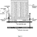
- FIG. 1 shows a radiator.
- controller assembly 106 controls water flow through hydronic emitter (radiator) 101 via a valve not explicitly shown to achieve a desired temperature delta between inlet 102 and outlet 103.
- Controller assembly 106 may support heating and/or cooling environmental systems.
- water flow pipe 107 transports heated water to hydronic emitter 101 through inlet 102.
- water flow 107 transports cooled water.
- Water return pipe 108 returns the expended water from hydronic emitter 101 through outlet 103.
- Controller assembly 106 measures the inlet and outlet temperatures through temperature sensors 104 and 105, respectively, and adjusts the water flow through hydronic emitter 101 so that the measured temperature delta approximately equals the target temperature delta, where the temperature delta equals the temperature difference between the outlet temperature and the inlet temperature. For example, when controller assembly 106 is operating in the heating mode and receives a temperature setpoint and a room temperature indication from an associated thermostat, controller assembly 106 adjusts the water flow though hydronic emitter 101 so that the hydronic emitter 101 provides an appropriate power output to a corresponding environmental entity (for example, a room).
- a corresponding environmental entity for example, a room
- controller assembly 106 repeats the above actions based on the updated room temperature obtained from the associated thermostat, where the updated temperature difference is the difference between the updated room temperature and the temperature setpoint. Consequently, controller assembly 106 modulates the water flow through hydronic emitter 101 (by varying the valve position of hydronic emitter 101) as the room temperature approaches the temperature setpoint.
- Controller assembly 106 may connect to temperature sensors 104 and 105 in a number of ways.
- temperature sensors 104 and 105 may be separate radio frequency module sensors that report the measured temperatures to controller assembly 106 periodically or by a wired communication.
- controller assembly 106 attached near inlet 102
- some embodiments may support controller assembly 106 being attached near outlet 103, where a valve controls water flow through outlet 103.
- FIG. 2 shows controller assembly 106 that controls water flow through a hydronic emitter in accordance with an embodiment.
- Controller assembly 106 obtains thermostat signal 251, which may be indicative of the temperature setpoint and current room temperature, via thermostat interface 204. Controller assembly 106 may receive signal 251 through various communication media, including wireless or wired channels using different communication protocols.
- Processor 201 processes signal 251 in accordance with computer readable instructions obtained from memory device 206.
- the computer readable instructions may reflect flowchart 400 and/or flowchart 900 shown in in Figures 4 and 9 , respectively, as will be discussed.
- processor 201 controls water flow though hydronic emitter 101 by controlling a valve through movement actuator 202.
- movement actuator 202 may comprises a precision motor drive that drives valve shaft 210 as instructed by processor 201.
- Processor 201 also obtains measured temperatures measured at inlet 102 and outlet 103 via temperature sensor interface 203 from temperature sensors 104 and 105, respectively.
- the difference between inlet 102 and outlet 103 may referred as the measured temperature delta.
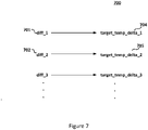
- the processor 201 determines a temperature difference between the room temperature and temperature setpoint obtained from signal 251. Processor 201 then accesses a data structure stored in memory device 205 that maps the temperature difference to a target temperature delta. An exemplary mapping is depicted as data structure 700 as shown in Figure 7 . For example, when the temperature difference equals diff_1 701, the target temperature delta equals target_temp_delta_1 704. Processor 201 then drives valve shaft 210 so that the measured temperature delta approximately equals the target_temp_delta_1 704.
- processor 201 After the measured temperature delta reaches target_temp_delta_1 704, processor 201 obtains the updated room temperature from the associated thermostat and consequently the updated temperature difference. For example, referring to Figure 7 , when the updated temperature equals diff_2 702, the target temperature delta equals target_temp_delta 705. Processor 201 then drives valve shaft 210 so that the measured temperature delta approximately equals the target temp delta_1 705.
- the computing system environment may include a computing device wherein the processes (for example, shown in Figures 4 and 9 ) discussed herein may be implemented.
- the computing device may have a processor 201 for controlling overall operation of the computing device and its associated components, including RAM, ROM, communications module, and memory devices 205 and 206.
- the computing device typically includes a variety of computer readable media.
- Computer readable media may be any available media that may be accessed by computing device and include both volatile and nonvolatile media, removable and non-removable media.
- computer readable media may comprise a combination of computer storage media and communication media.
- Computer storage media may include volatile and nonvolatile, removable and non-removable media implemented in any method or technology for storage of information such as computer readable instructions, data structures, program modules or other data.
- Computer storage media include, but is not limited to, random access memory (RAM), read only memory (ROM), electronically erasable programmable read only memory (EEPROM), flash memory or other memory technology, CD-ROM, digital versatile disks (DVD) or other optical disk storage, magnetic cassettes, magnetic tape, magnetic disk storage or other magnetic storage devices, or any other medium that can be used to store the desired information and that can be accessed by the computing device.
- Communication media typically embodies computer readable instructions, data structures, program modules or other data in a modulated data signal such as a carrier wave or other transport mechanism and includes any information delivery media.
- Modulated data signal is a signal that has one or more of its characteristics set or changed in such a manner as to encode information in the signal.
- communication media includes wired media such as a wired network or direct-wired connection, and wireless media such as acoustic, RF, infrared and other wireless media.
- memory devices 205 and 206 may be physically implemented with a single memory device.
- embodiments water flow is controlled separately for different hydronic emitters associated with different portions (for example, rooms) of the building structure (for example, a house) rather than at the boiler itself. Consequently, embodiments may support multiple heating/cooling zones.
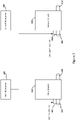
- Figure 3 shows an under-floor heating/cooling manifold with a plurality of emitters 303 and 304.
- Controller assemblies 301 and 302 control water flow through emitters 303 and 304, respectively, based on signals obtained from thermostats 305 and 306, respectively.
- Inlets 307 and 309 may connect to water flow pipe 107 and outlets 308 and 310 may connect to water return pipe 108 as shown in Figure 1 .
- Controller assemblies 301 and 302 control water flow through emitters 303 and 304, respectively, based on measured temperature deltas measured between inlet 307 and outlet 308 and between inlet 309 and outlet 310, respectively. Consequently, controller assemblies 301 and 302 may support separate first and second heating/cooling zones, respectively.
- controller assembly 301 is electrically coupled to temperature sensors thermally coupled to inlet 307 and outlet 308 while controller assembly 302 is electrically coupled to temperature sensors thermally coupled to inlet 309 and outlet 310.
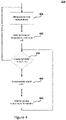
- FIG. 4 shows flowchart 400 of the operation of controller assembly 106 in accordance with an embodiment.
- processor 201 initiates process 400 by obtaining the room temperature and setpoint from the associated thermostat and consequently determines the temperature difference.
- Processor 201 then accesses data structure 700 to obtain the target temperature delta at block 402.
- processor 201 incrementally adjusts a valve controlling water flow at inlet 102 so that the measured temperature delta incrementally approaches (converges to) the target temperature delta.
- processor 201 obtains the updated room temperature from the associated thermostat at block 401. Blocks 401-405 are repeated until the room temperature reaches a desired temperature (for example, the temperature setpoint or predetermined temperature offset from the setpoint).
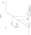
- Figure 5 shows exemplary relationship 500 between an emitter power output and a temperature difference in accordance with an embodiment.
- the emitter power output is at the maximum capability (100%) when the temperature difference is at or above a first predetermined value (shown as 1.5C degrees in exemplary relationship 500).
- the emitter power output varies from 100% to 1%.
- the water flow is stopped so that the power output equals 0%.
- Figure 6 shows exemplary relationship 600 between an emitter power output and a measured temperature delta of the emitter in accordance with an embodiment.
- temperature difference 501 corresponds to power output 502.
- power output 501 corresponds to target temperature delta 601. Consequently, temperature difference 501 maps to target temperature delta 601 as reflected in data structure 700.
- temperature difference 503 corresponds to power output 504 which corresponds to target temperature delta 602.
- FIG 8 shows mapping 800 between a temperature difference and a resulting position of a valve controlling water flow through emitter 101 in accordance with an embodiment.
- mapping 700 presents the target temperature delta for an emitter but does not explicitly present the corresponding valve position. Consequently, controller assembly 106 when executing computer readable instructions corresponding to flowchart 400 incrementally adjusts the valve until the measured temperature delta approximately equals the target temperature delta. When reaching the target temperature delta, processor 201 can determine the resulting position of the valve. Corresponding entries in mapping 800 may be generated for the particular temperature difference.
- resulting_position_1 801 is mapped to diff_1 701 while there is no mapping for diff_2 702 (where value 802 is "to be determined") because, with the hypothetical example, processor 201 has not encountered corresponding diff_2 702.
- processor 201 may utilize the generated entries in mapping 800 to expedite control by controller assembly 106.
- the above approach may be advantageous to generating a fixed mapping for mapping 800 when characteristics of the emitter and variability of the associated valve sufficiently differ from one configuration to another.
- Figure 9 shows process 900 of the operation of controller assembly 106 in accordance with an embodiment. Operation at blocks 901-902 and 905-907 is similar to that at blocks 401-402 and 403-405, respectively, as previously discussed with Figure 4 . However, when an entry has been generated in mapping 800 for a given temperature difference, process 900 adjusts the valve position in one step at block 904 without incrementally adjusting the valve and is consequently referred as the "quick mode.”
- processor 201 executes blocks 905-907 in a similar fashion as with blocks 403-405 of process 400.
- processor 201 can generate an entry for the temperature difference at block 908 by tracking the valve position at that event. Because process 900 is able to generate mapping 900, blocks 905-907 may be referred to as a "training mode.”
- the computer system may include at least one computer such as a microprocessor, digital signal processor, and associated peripheral electronic circuitry.
Landscapes
- Engineering & Computer Science (AREA)
- Chemical & Material Sciences (AREA)
- Combustion & Propulsion (AREA)
- Mechanical Engineering (AREA)
- General Engineering & Computer Science (AREA)
- Physics & Mathematics (AREA)
- Thermal Sciences (AREA)
- General Physics & Mathematics (AREA)
- Automation & Control Theory (AREA)
- Signal Processing (AREA)
- Fuzzy Systems (AREA)
- Sustainable Development (AREA)
- Remote Sensing (AREA)
- Life Sciences & Earth Sciences (AREA)
- Mathematical Physics (AREA)
- Steam Or Hot-Water Central Heating Systems (AREA)
- Control Of Temperature (AREA)
Description
- The present invention relates to a manifold or valve heating or cooling system and a method of controlling a fluid flowing through an emitter of such a system. Aspects of the disclosure relate to power modulating individual radiators, underfloor heating circuits, chilled beams or fan-coils for a heating/cooling system.
- Heating/cooling systems with hydronic emitters (including radiators, underfloor heating/cooling circuits, fan coils, chilled beams) are based on power transfer from one or more of the hydronic emitters to affect one or more environmental entities (for example, offices, apartments, conference rooms, and the like). Traditional approaches often switch on the heating when the temperature of the environmental entity falls below the setpoint and switch off the heating when the temperature rises above the setpoint. This approach typically exhibits various deficiencies. For example, the resulting temperature control is quite poor and may produce both temperature overshoot and undershoot of the desired temperature.
DE 202014103760 discloses a control device for controlling a thermostatic valve drive of a connection station of a heating system as a function of the room temperature, flow temperature and return temperature, such that a predetermined room temperature is achieved with the greatest possible temperature difference between the flow temperature and the return temperature. - According to a first aspect of the invention there is provided a controller for a manifold/valve heating/cooling system. The controller comprises: at least one controller assembly controlling the system, the at least one controller assembly including: a movement actuator configured to connect to a valve in order to control water flow through a hydronic emitter; a temperature sensor interface configured to interface to first and second temperature sensors, wherein the first temperature sensor and the second temperature sensor measure an inlet temperature and an outlet temperature, respectively, of the hydronic emitter and wherein a measured temperature delta is a difference between the inlet and outlet temperatures; a thermostat interface configured to obtain a temperature setpoint and a room temperature for an environmental entity; and a computer device comprising: a processor; a first memory device; and a second memory device storing computer-readable instructions that, when executed by the processor, cause the at least one controller assembly to perform: obtaining, through the thermostat interface, the temperature setpoint and the room temperature; accessing a target temperature delta from a first data structure stored on the first memory device, wherein the first data structure maps the target temperature delta to a temperature difference between the temperature setpoint and the room temperature; controlling the movement actuator to adjust the valve so that water flow through the hydronic emitter results in the measured temperature delta approximately equaling the target temperature delta comprising: mapping, in a second data structure stored in the first memory device, a resulting position of the valve to the temperature difference when the measured temperature delta approximately equals the target temperature delta; when a mapping for the temperature difference is stored in the second data structure, instructing the movement actuator to directly adjust the valve to the resulting position; when the mapping for the temperature difference is not stored in the second data structure, incrementally controlling the movement actuator to adjust the valve so that water flow through the hydronic emitter corresponds to an incremental change of the measured temperature delta; waiting for the measured temperature delta to stabilize; and repeating the incrementally controlling and the waiting until the measured temperature delta approximately equals the target temperature delta; and repeating the obtaining, the accessing, and the controlling for an updated room temperature.
- According to a second aspect, there is provided a method for controlling a fluid flowing through a first hydronic emitter of a heating/cooling system. The method comprises: obtaining, through a thermostat interface, a first temperature setpoint and a first room temperature for a first environmental entity; accessing a first target temperature delta from a first data structure stored on a memory device, wherein the first data structure maps the first temperature delta to a temperature difference between the first temperature setpoint and the first room temperature; measuring, through a temperature sensor interface configured to interface to first and second temperature sensors, a first measured temperature delta between a first inlet and a first outlet of the first hydronic emitter, wherein the first measured temperature delta is a difference between the first inlet and outlet temperatures; adjusting, through a first movement actuator, a first valve so that fluid flow through the first hydronic emitter results in the first measured temperature delta approximately equaling the first target temperature delta, comprising: mapping, in a second data structure stored on a memory device, a resulting position of the first valve to the temperature difference when the first measured temperature delta approximately equals the first target temperature delta; when a mapping for the temperature difference and the resulting position is stored in a the second data structure, instructing the first movement actuator to directly adjust the first valve to the resulting position; when the mapping for the temperature difference and the resulting position is not stored in the data structure, incrementally controlling the first movement actuator to adjust the first valve so that fluid flow through the first emitter corresponds to an incremental change of the first measured temperature delta; waiting for the first measured temperature delta to stabilize; and repeating the incrementally controlling and the waiting until the first measured temperature delta approximately equals the first target temperature delta; and repeating the obtaining, the accessing, the measuring, and the adjusting for an updated first room temperature.
- A delta temperature room control is provided using a high precision movement actuator fitted with two pipe temperature sensors to power modulate individual radiators, underfloor heating circuits, chilled beams or fan-coils to provide energy efficiency for individual room heating/cooling control.
- According to the invention, the controller assembly includes a movement actuator configured to connect to a valve in order to control water flow through a hydronic emitter and a temperature sensor interface configured to interface to first and second temperature sensors that measure an inlet temperature and an outlet temperature, respectively, of the hydronic emitter, where a measured temperature delta is a difference between the inlet and outlet temperatures. A thermostat interface obtains a temperature setpoint and a room temperature for an environmental entity such as a room. The controller assembly obtains a target temperature delta from the difference of the temperature setpoint and room temperature and subsequently controls the movement actuator to adjust a valve resulting in water flow through the hydronic emitter based on the target temperature delta. The controller assembly may repeat the above actions for an updated room temperature.
- According to the invention, a controller assembly incrementally controls the movement actuator to adjust the valve so that water flow through the hydronic emitter corresponds to an incremental change of the measured temperature delta, waits for the measured temperature delta to stabilize, and repeats the above actions until the measured temperature delta approximately equals the target temperature delta.
- According to the invention, a controller assembly generates a data structure that maps a resulting position of the valve to a temperature difference between the temperature setpoint and room temperature when the measured temperature delta approximately equals the target temperature delta.
- According to the invention, when a mapping of a valve position and a temperature difference between the temperature setpoint and room temperature is stored a data structure, a controller assembly instructs the movement actuator to directly adjust the valve to the resulting position. When the mapping is not stored in the data structure, the controller assembly incrementally controls the movement actuator to adjust the valve so that water flow through the hydronic emitter corresponds to an incremental change of the measured temperature delta. The controller assembly then waits for the measured temperature delta to stabilize and repeats the above actions until the measured temperature delta approximately equals the target temperature delta.
- According to an embodiment, the controller for a manifold heating/cooling system includes first and second controller assemblies that control first and second emitters, respectively. This enables the system to control multiple heating/cooling zones.
- According to a third aspect there is provided a software product comprising instructions that, when executed by a processor, are suitable to cause the controller of the first aspect to perform the method of the second aspect.
- The foregoing summary of the invention, as well as the following detailed description of exemplary embodiments of the invention, is better understood when read in conjunction with the accompanying drawings, which are included by way of example only, and not by way of limitation with regard to the claimed invention.
-
Figure 1 shows a radiator. -
Figure 2 shows a controller assembly that controls water flow through a hydronic emitter in accordance with an embodiment. -
Figure 3 shows an under-floor heating/cooling manifold with a plurality of emitters. -
Figure 4 shows a flowchart of the operation of a controller assembly in accordance with an embodiment. -
Figure 5 shows an exemplary relationship between an emitter power output and a temperature difference in accordance with an embodiment. -
Figure 6 shows an exemplary relationship between an emitter power output and a measured temperature delta of the emitter in accordance with an embodiment. -
Figure 7 shows a mapping between a temperature difference and a target temperature delta for an emitter in accordance with an embodiment. -
Figure 8 shows a mapping between a temperature difference and a resulting position of a valve controlling water flow through an emitter in accordance with an embodiment. -
Figure 9 shows a flowchart of the operation of a controller assembly in accordance with an embodiment. - A heating/cooling system supports individual room load compensation for use with both modulated and non-modulated boilers. The control uses a precision movement actuator connected to a valve or manifold. Two remote pipe temperature sensors are attached to the actuator, where one is attached to the emitter flow pipe and the other is attached to the emitter return pipe.
- The control "modulates" the heating/cooling emitter by varying flow rate through the emitter dependent upon the temperature delta across the emitter flow and return temperature such that the power given off by the emitter is modulated. The power level required by a control device (for example, thermostat) from the emitter is controlled by the difference from the room temperature to the setpoint. For example, in the case of a hot water radiator when the room temperature is greater than 1.5C degrees from the setpoint, the actuator will be opened to full flow (100% power output) by reducing the temperature delta between the emitter flow and return.
- As the room temperature approaches the setpoint, the actuator may adjust the flow rate by increasing the temperature delta between the emitter flow and return. This adjustment causes the emitter power output to be reduced. With some embodiments, the power output can be modulated between 1% and 100%. As the room temperature reaches the setpoint, the actuator may restrict the flow to match the room energy losses. Only when the room temperature exceeds the setpoint by, for example, 0.2C degrees will the actuator close the water flow completely.
- This control approach may ensure that there is no overshoot or undershoot of the room temperature and also ensure that the delta temperature control will achieve this without continually switching the boiler/pump on and/or off. Because the temperature delta control (TDC) approach is implemented at the emitter rather than at the system boiler, individual room modulation control can be achieved using a standard boiler.
- The delta temperature control approach has various advantages with respect to traditional approaches. With under floor heating (UFH), the actuator may be assembled to the heating manifold and controlled from the room thermostat via a wiring center. For radiators the actuator may be assembled to the radiator with either wired pipe sensors or wireless remote pipe sensors. Room control may be obtained from the room thermostat either via wired or wireless channels. For fan coil control the actuator may be assembled to the flow/return pipe in the fan coil with wired pipe sensors, where control may be from the fan coil thermostat via either wired or wireless channels.
-
Figure 1 shows a radiator. As will be further discussed,controller assembly 106 controls water flow through hydronic emitter (radiator) 101 via a valve not explicitly shown to achieve a desired temperature delta betweeninlet 102 andoutlet 103. -
Controller assembly 106 may support heating and/or cooling environmental systems. When supporting a heating mode,water flow pipe 107 transports heated water tohydronic emitter 101 throughinlet 102. When supporting a cooling mode,water flow 107 transports cooled water.Water return pipe 108 returns the expended water fromhydronic emitter 101 throughoutlet 103. -
Controller assembly 106 measures the inlet and outlet temperatures throughtemperature sensors hydronic emitter 101 so that the measured temperature delta approximately equals the target temperature delta, where the temperature delta equals the temperature difference between the outlet temperature and the inlet temperature. For example, whencontroller assembly 106 is operating in the heating mode and receives a temperature setpoint and a room temperature indication from an associated thermostat,controller assembly 106 adjusts the water flow thoughhydronic emitter 101 so that thehydronic emitter 101 provides an appropriate power output to a corresponding environmental entity (for example, a room). When the measured temperature delta approximately equals the target temperature delta,controller assembly 106 repeats the above actions based on the updated room temperature obtained from the associated thermostat, where the updated temperature difference is the difference between the updated room temperature and the temperature setpoint. Consequently,controller assembly 106 modulates the water flow through hydronic emitter 101 (by varying the valve position of hydronic emitter 101) as the room temperature approaches the temperature setpoint. -
Controller assembly 106 may connect totemperature sensors temperature sensors assembly 106 periodically or by a wired communication. - While
Figure 1 showscontroller assembly 106 attached nearinlet 102, some embodiments may supportcontroller assembly 106 being attached nearoutlet 103, where a valve controls water flow throughoutlet 103. -
Figure 2 showscontroller assembly 106 that controls water flow through a hydronic emitter in accordance with an embodiment. -
Controller assembly 106 obtainsthermostat signal 251, which may be indicative of the temperature setpoint and current room temperature, viathermostat interface 204.Controller assembly 106 may receive signal 251 through various communication media, including wireless or wired channels using different communication protocols. -
Processor 201 processes signal 251 in accordance with computer readable instructions obtained frommemory device 206. For example, the computer readable instructions may reflectflowchart 400 and/orflowchart 900 shown in inFigures 4 and9 , respectively, as will be discussed. Based on information obtained fromsignal 251,processor 201 controls water flow thoughhydronic emitter 101 by controlling a valve throughmovement actuator 202. For example,movement actuator 202 may comprises a precision motor drive that drivesvalve shaft 210 as instructed byprocessor 201. -
Processor 201 also obtains measured temperatures measured atinlet 102 andoutlet 103 viatemperature sensor interface 203 fromtemperature sensors inlet 102 andoutlet 103 may referred as the measured temperature delta. - The
processor 201 determines a temperature difference between the room temperature and temperature setpoint obtained fromsignal 251.Processor 201 then accesses a data structure stored inmemory device 205 that maps the temperature difference to a target temperature delta. An exemplary mapping is depicted asdata structure 700 as shown inFigure 7 . For example, when the temperature difference equalsdiff_1 701, the target temperature delta equalstarget_temp_delta_1 704.Processor 201 then drivesvalve shaft 210 so that the measured temperature delta approximately equals thetarget_temp_delta_1 704. Several approaches for achieving this objective will be presented when discussingFigures 4 and9 . - After the measured temperature delta reaches target_temp_delta_1 704,
processor 201 obtains the updated room temperature from the associated thermostat and consequently the updated temperature difference. For example, referring toFigure 7 , when the updated temperature equalsdiff_2 702, the target temperature delta equalstarget_temp_delta 705.Processor 201 then drivesvalve shaft 210 so that the measured temperature delta approximately equals thetarget temp delta_1 705. - With reference to
Figure 2 , the computing system environment may include a computing device wherein the processes (for example, shown inFigures 4 and9 ) discussed herein may be implemented. The computing device may have aprocessor 201 for controlling overall operation of the computing device and its associated components, including RAM, ROM, communications module, andmemory devices - Computer storage media may include volatile and nonvolatile, removable and non-removable media implemented in any method or technology for storage of information such as computer readable instructions, data structures, program modules or other data. Computer storage media include, but is not limited to, random access memory (RAM), read only memory (ROM), electronically erasable programmable read only memory (EEPROM), flash memory or other memory technology, CD-ROM, digital versatile disks (DVD) or other optical disk storage, magnetic cassettes, magnetic tape, magnetic disk storage or other magnetic storage devices, or any other medium that can be used to store the desired information and that can be accessed by the computing device.
- Communication media typically embodies computer readable instructions, data structures, program modules or other data in a modulated data signal such as a carrier wave or other transport mechanism and includes any information delivery media. Modulated data signal is a signal that has one or more of its characteristics set or changed in such a manner as to encode information in the signal. By way of example, and not limitation, communication media includes wired media such as a wired network or direct-wired connection, and wireless media such as acoustic, RF, infrared and other wireless media.
- With some embodiments,
memory devices - Traditional approaches often have only a single thermostat and consequently do not support multiple thermostats. With traditional approaches, a boiler provides a single water temperature applicable to the entire building structure.
- With an aspect of the embodiments, water flow is controlled separately for different hydronic emitters associated with different portions (for example, rooms) of the building structure (for example, a house) rather than at the boiler itself. Consequently, embodiments may support multiple heating/cooling zones.
-
Figure 3 shows an under-floor heating/cooling manifold with a plurality ofemitters Controller assemblies emitters thermostats Inlets water flow pipe 107 andoutlets water return pipe 108 as shown inFigure 1 . -
Controller assemblies emitters inlet 307 andoutlet 308 and betweeninlet 309 andoutlet 310, respectively. Consequently,controller assemblies controller assembly 301 is electrically coupled to temperature sensors thermally coupled toinlet 307 andoutlet 308 whilecontroller assembly 302 is electrically coupled to temperature sensors thermally coupled toinlet 309 andoutlet 310. -
Figure 4 showsflowchart 400 of the operation ofcontroller assembly 106 in accordance with an embodiment. Atblock 401processor 201initiates process 400 by obtaining the room temperature and setpoint from the associated thermostat and consequently determines the temperature difference.Processor 201 then accessesdata structure 700 to obtain the target temperature delta atblock 402. - At blocks 403-405,
processor 201 incrementally adjusts a valve controlling water flow atinlet 102 so that the measured temperature delta incrementally approaches (converges to) the target temperature delta. When the measured temperature delta approximately equals the target temperature delta,processor 201 obtains the updated room temperature from the associated thermostat atblock 401. Blocks 401-405 are repeated until the room temperature reaches a desired temperature (for example, the temperature setpoint or predetermined temperature offset from the setpoint). -
Figure 5 showsexemplary relationship 500 between an emitter power output and a temperature difference in accordance with an embodiment. The emitter power output is at the maximum capability (100%) when the temperature difference is at or above a first predetermined value (shown as 1.5C degrees in exemplary relationship 500). - As the temperature difference varies from the first predetermined value to a second predetermined value (shown as 0C degrees in exemplary relationship 500), the emitter power output varies from 100% to 1%. When the temperature difference reaches a third predetermined value, the water flow is stopped so that the power output equals 0%.
-
Figure 6 showsexemplary relationship 600 between an emitter power output and a measured temperature delta of the emitter in accordance with an embodiment. - From
relationships Figure 7 . For example, referring toFigure 5 ,temperature difference 501 corresponds topower output 502. Fromrelationship 600 shown inFigure 6 ,power output 501 corresponds to targettemperature delta 601. Consequently,temperature difference 501 maps to targettemperature delta 601 as reflected indata structure 700. Similarly,temperature difference 503 corresponds topower output 504 which corresponds to targettemperature delta 602. -
Figure 8 showsmapping 800 between a temperature difference and a resulting position of a valve controlling water flow throughemitter 101 in accordance with an embodiment. Referring toFigure 7 ,mapping 700 presents the target temperature delta for an emitter but does not explicitly present the corresponding valve position. Consequently,controller assembly 106 when executing computer readable instructions corresponding to flowchart 400 incrementally adjusts the valve until the measured temperature delta approximately equals the target temperature delta. When reaching the target temperature delta,processor 201 can determine the resulting position of the valve. Corresponding entries inmapping 800 may be generated for the particular temperature difference. For example,resulting_position_1 801 is mapped to diff_1 701 while there is no mapping for diff_2 702 (wherevalue 802 is "to be determined") because, with the hypothetical example,processor 201 has not encountered correspondingdiff_2 702. As will be discussed,processor 201 may utilize the generated entries inmapping 800 to expedite control bycontroller assembly 106. The above approach may be advantageous to generating a fixed mapping formapping 800 when characteristics of the emitter and variability of the associated valve sufficiently differ from one configuration to another. -
Figure 9 showsprocess 900 of the operation ofcontroller assembly 106 in accordance with an embodiment. Operation at blocks 901-902 and 905-907 is similar to that at blocks 401-402 and 403-405, respectively, as previously discussed withFigure 4 . However, when an entry has been generated inmapping 800 for a given temperature difference,process 900 adjusts the valve position in one step atblock 904 without incrementally adjusting the valve and is consequently referred as the "quick mode." - However, if an entry has not been generated in mapping for a given temperature difference,
processor 201 executes blocks 905-907 in a similar fashion as with blocks 403-405 ofprocess 400. In addition, when the measured temperature delta approximately equals the target temperature delta,processor 201 can generate an entry for the temperature difference atblock 908 by tracking the valve position at that event. Becauseprocess 900 is able to generatemapping 900, blocks 905-907 may be referred to as a "training mode." - As can be appreciated by one skilled in the art, a computer system with an associated computer-readable medium containing instructions for controlling the computer system can be utilized to implement the exemplary embodiments that are disclosed herein. The computer system may include at least one computer such as a microprocessor, digital signal processor, and associated peripheral electronic circuitry.
Claims (10)
- A controller for a manifold/valve heating/cooling system comprising:
at least one controller assembly (106) controlling the system, the at least one controller assembly including:a movement actuator (202) configured to connect to a valve in order to control water flow through a hydronic emitter (101);a temperature sensor interface (203) configured to interface to first and second temperature sensors (104, 105), wherein the first temperature sensor and the second temperature sensor measure an inlet temperature and an outlet temperature, respectively, of the hydronic emitter and wherein a measured temperature delta is a difference between the inlet and outlet temperatures;a thermostat interface (204) configured to obtain a temperature setpoint and a room temperature for an environmental entity; anda computer device comprising:a processor (201);a first memory device (205); anda second memory device (206) storing computer-readable instructions that, when executed by the processor, cause the at least one controller assembly to perform:obtaining, through the thermostat interface, the temperature setpoint and the room temperature;accessing a target temperature delta from a first data structure stored on the first memory device, wherein the first data structure maps the target temperature delta to a temperature difference between the temperature setpoint and the room temperature;controlling the movement actuator to adjust the valve so that water flow through the hydronic emitter results in the measured temperature delta approximately equaling the target temperature delta comprising:mapping, in a second data structure stored in the first memory device (205), a resulting position of the valve to the temperature difference when the measured temperature delta approximately equals the target temperature delta;when a mapping for the temperature difference is stored in the second data structure, instructing the movement actuator (202) to directly adjust the valve to the resulting position;when the mapping for the temperature difference is not stored in the second data structure, incrementally controlling the movement actuator to adjust the valve so that water flow through the hydronic emitter (102) corresponds to an incremental change of the measured temperature delta;waiting for the measured temperature delta to stabilize; andrepeating the incrementally controlling and the waiting until the measured temperature delta approximately equals the target temperature delta; andrepeating the obtaining, the accessing, and the controlling for an updated room temperature. - The controller of claim 1, wherein the second memory device (206) stores computer-readable instructions that, when executed by the processor (201), cause the at least one controller assembly (106) to perform:incrementally controlling the movement actuator to adjust the valve so that water flow through the hydronic emitter (101) corresponds to an incremental change of the measured temperature delta;waiting for the measured temperature delta to stabilize; andrepeating the incrementally controlling and the waiting until the measured temperature delta approximately equals the target temperature delta.
- The controller of any preceding claim further comprising a first and a second controller assembly (301, 302), wherein:
the first controller assembly controls water flow through a first emitter (303) and comprises a first processor and a third memory device storing computer-readable instructions that, when executed by the first processor, cause the first controller assembly to perform:
accessing a first target temperature delta for the first emitter from the first data structure provided by a first thermostat (305); and wherein:
the second controller assembly controls water flow through a second emitter (304) and comprises a second processor and a fourth memory device storing computer-readable instructions that, when executed by the second processor, cause the second controller assembly to perform:
accessing a second target temperature delta for the second emitter from second data provided by a second thermostat (306). - A method for controlling a fluid flowing through a first hydronic emitter (303) of a heating/cooling system, the method comprising:obtaining, through a thermostat interface (204), a first temperature setpoint and a first room temperature for a first environmental entity;accessing a first target temperature delta from a first data structure stored on a memory device, wherein the first data structure maps the first temperature delta to, a temperature difference between the first temperature setpoint and the first room temperature;measuring, through a temperature sensor interface configured to interface to first and second temperature sensors, a first measured temperature delta between a first inlet (307) and a first outlet (308) of the first hydronic emitter, wherein the first measured temperature delta is a difference between the first inlet and outlet temperatures;adjusting, through a first movement actuator (202), a first valve so that fluid flow through the first hydronic emitter results in the first measured temperature delta approximately equaling the first target temperature delta, comprising:mapping, in a second data structure stored on a memory device, a resulting position of the first valve to the temperature difference when the first measured temperature delta approximately equals the first target temperature delta;when a mapping for the temperature difference and the resulting position is stored in the second data structure, instructing the first movement actuator (202) to directly adjust the first valve to the resulting position;when the mapping for the temperature difference and the resulting position is not stored in the data structure, incrementally controlling the first movement actuator to adjust the first valve so that fluid flow through the first emitter (303) corresponds to an incremental change of the first measured temperature delta;waiting for the first measured temperature delta to stabilize; andrepeating the incrementally controlling and the waiting until the first measured temperature delta approximately equals the first target temperature delta; andrepeating the obtaining, the accessing, the measuring, and the adjusting for an updated first room temperature.
- A method of claim 4 further comprising:incrementally controlling the first movement actuator (202) to adjust the first valve so that fluid flow through the first hydronic emitter (303) corresponds to an incremental change of the first measured temperature delta;waiting for the first measured temperature delta to stabilize; andrepeating the incrementally controlling and the waiting until the first measured temperature delta approximately equals the first target temperature delta.
- A method of any of claims 4 or 5 further comprising:obtaining, through the thermostat interface (204), a second temperature setpoint and a second room temperature for a second environmental entity;accessing a second target temperature delta based on the second temperature setpoint and the second room temperature;measuring a second measured temperature delta between a second inlet (309) and a second outlet (310) of a second emitter (304), wherein the second measured temperature delta is a difference between the second inlet and outlet temperatures; andadjusting, through a second movement actuator, a second valve so that fluid flow through the second emitter corresponds to the second measured temperature delta approximately equaling the second target temperature delta.
- A method of any of claims 4 to 6, wherein the fluid comprises water; and optionally:
a heating source of the heating/cooling system is a standard boiler. - A method of any of claims 4 to 7 further comprising:
when a difference between the first temperature setpoint and the first room temperature is greater than a first predetermined amount, setting the first target temperature delta so that the first valve is fully open to obtain a maximum power level from the first hydronic emitter (303); and optionally:
when the difference between the first temperature setpoint and the first room temperature is less than the first predetermined amount and greater than a second predetermined amount, setting the first target temperature delta so that the first valve is partially open to obtain a partial power level from the first hydronic emitter; and optionally:
when the difference between the first temperature setpoint and the first room temperature is less than a third predetermined amount, fully closing the first valve so that fluid flow is approximately stopped. - A method of claim 8, wherein the third predetermined amount corresponds to the first room temperature exceeding the first temperature setpoint by approximately 0.2C degrees.
- A software product comprising instructions that, when executed by a processor (201), are suitable to cause the controller of claim 1 to perform the method of claim 4.
Applications Claiming Priority (1)
| Application Number | Priority Date | Filing Date | Title |
|---|---|---|---|
| US15/962,437 US10527296B2 (en) | 2018-04-25 | 2018-04-25 | Temperature delta control for a hydronic heating/cooling system |
Publications (2)
| Publication Number | Publication Date |
|---|---|
| EP3561399A1 EP3561399A1 (en) | 2019-10-30 |
| EP3561399B1 true EP3561399B1 (en) | 2022-08-17 |
Family
ID=66290227
Family Applications (1)
| Application Number | Title | Priority Date | Filing Date |
|---|---|---|---|
| EP19171229.8A Active EP3561399B1 (en) | 2018-04-25 | 2019-04-25 | Temperature delta control for a hydronic heating/cooling system |
Country Status (3)
| Country | Link |
|---|---|
| US (1) | US10527296B2 (en) |
| EP (1) | EP3561399B1 (en) |
| CN (1) | CN110397981B (en) |
Families Citing this family (6)
| Publication number | Priority date | Publication date | Assignee | Title |
|---|---|---|---|---|
| US10697650B2 (en) * | 2016-07-27 | 2020-06-30 | Computime Ltd. | Automatic balance valve control |
| US20200108687A1 (en) * | 2018-10-03 | 2020-04-09 | Red Dot Corporation | Automatic temperature control actuator |
| IT202200017151A1 (en) * | 2022-08-10 | 2024-02-10 | Ivar Spa | METHOD FOR REGULATING THE FLOW OF FLUID TO A HEATING ELEMENT AND RELATED DEVICE |
| CN115540038A (en) * | 2022-08-22 | 2022-12-30 | 安徽辰吉新能源科技有限公司 | A method, system and storage medium for controlling water floor heating temperature |
| US12613050B2 (en) * | 2022-09-19 | 2026-04-28 | Microsoft Technology Licensing, Llc | Machine teaching with method of moments for mechanical systems |
| CN115682463B (en) * | 2022-09-28 | 2025-07-01 | 中建八局发展建设有限公司 | A temperature regulation system and method for the construction of a linear accelerator room main structure |
Family Cites Families (17)
| Publication number | Priority date | Publication date | Assignee | Title |
|---|---|---|---|---|
| AUPR212700A0 (en) * | 2000-12-18 | 2001-01-25 | Southcorp Australia Pty Ltd | Thermostat to provide a water heater with adaptive adjustment to controlled water temperature |
| CN201212720Y (en) * | 2008-04-16 | 2009-03-25 | 谭文胜 | Apparatus for controlling central air-conditioning end to supply backwater temperature difference |
| JP2010196946A (en) * | 2009-02-24 | 2010-09-09 | Daikin Ind Ltd | Heat pump system |
| EP3128143B1 (en) * | 2009-06-18 | 2018-05-23 | Cummins IP, Inc. | System for reductant line heating control |
| US9204578B2 (en) * | 2010-02-09 | 2015-12-01 | It Aire Inc. | Systems and methods for cooling data centers and other electronic equipment |
| EP2466220B1 (en) * | 2010-02-24 | 2016-11-16 | Mitsubishi Electric Corporation | Air conditioning system and method of controlling air conditioning system |
| US9273889B2 (en) * | 2011-04-21 | 2016-03-01 | United States Thermoamp Inc. | Monitoring and control system for a heat pump |
| PL2636959T3 (en) | 2012-03-05 | 2017-07-31 | Kermi Gmbh | Heater control |
| US20130240172A1 (en) * | 2012-03-13 | 2013-09-19 | Victaulic Company | Hydronic System and Control Method |
| CN103574829B (en) * | 2012-07-18 | 2016-04-13 | 同方泰德国际科技(北京)有限公司 | A kind of energy-saving control method of air-conditioner set |
| US10119711B2 (en) * | 2013-12-17 | 2018-11-06 | Optimum Energy Llc | Air handler unit including a smart valve |
| DE202014103760U1 (en) | 2014-08-13 | 2015-08-14 | Carnotherm Gmbh | heating system |
| JP5869648B1 (en) * | 2014-10-29 | 2016-02-24 | 木村工機株式会社 | Air conditioning system |
| DE102014226450A1 (en) | 2014-12-18 | 2016-06-23 | Robert Bosch Gmbh | Method for carrying out an automated hydraulic balancing of a refining plant |
| US20170219219A1 (en) * | 2016-02-01 | 2017-08-03 | Keith A. Miller | Demand based hvac (heating, ventilation, air conditioning) control |
| US10697650B2 (en) | 2016-07-27 | 2020-06-30 | Computime Ltd. | Automatic balance valve control |
| CN206755310U (en) * | 2017-09-14 | 2017-12-15 | 北京华远意通热力科技股份有限公司 | A kind of warm heat supply control system of timesharing point |
-
2018
- 2018-04-25 US US15/962,437 patent/US10527296B2/en active Active
-
2019
- 2019-04-24 CN CN201910335355.9A patent/CN110397981B/en active Active
- 2019-04-25 EP EP19171229.8A patent/EP3561399B1/en active Active
Also Published As
| Publication number | Publication date |
|---|---|
| CN110397981B (en) | 2021-07-13 |
| US10527296B2 (en) | 2020-01-07 |
| CN110397981A (en) | 2019-11-01 |
| US20190331349A1 (en) | 2019-10-31 |
| EP3561399A1 (en) | 2019-10-30 |
Similar Documents
| Publication | Publication Date | Title |
|---|---|---|
| US10527296B2 (en) | Temperature delta control for a hydronic heating/cooling system | |
| RU2660721C2 (en) | Device and method for controlling opening of valve in hvac system | |
| US6250560B1 (en) | Variable-air-volume diffuser actuator assembly and method | |
| EP3276267B1 (en) | Automatic balance valve assembly, method for controlling water flow and computer-readable medium | |
| US20170219219A1 (en) | Demand based hvac (heating, ventilation, air conditioning) control | |
| US10578318B2 (en) | Single thermostat with multiple thermostatic radiator valve controllers | |
| EP3699500B1 (en) | Modulated heating/cooling system control | |
| EP3115703B1 (en) | Control of heating, ventilation, air conditioning | |
| US20080277488A1 (en) | Method for Controlling HVAC Systems | |
| US11754296B2 (en) | System and method for controlling a fluid vector temperature in order to heat a building | |
| RU2570784C2 (en) | Method and plant of temperature regulation in building | |
| EP4567341A1 (en) | Control method for environmental conditioning device, environmental conditioning device, and storage medium | |
| US10712021B2 (en) | Pulse modulated heating, ventilation, and air conditioning (HVAC) control | |
| EP3841332B1 (en) | Determination of hydronic valve opening point | |
| HK40013758B (en) | Temperature delta control for a hydronic heating/cooling system | |
| HK40013758A (en) | Temperature delta control for a hydronic heating/cooling system | |
| US20250354698A1 (en) | Improvements to heating systems | |
| EP3859485B1 (en) | Adaptive boiler control | |
| EP3339753B1 (en) | System and method for enforcing a manual temperature setpoint within a smart thermal management system | |
| GB2567034A (en) | Radiator thermostat (17500) | |
| HK40031848A (en) | Modulated heating/cooling system control | |
| HK40020324A (en) | Pulse modulated heating, ventilation, and air conditioning (hvac) control | |
| GB2619355A (en) | Improvements to heating systems | |
| JPH0339228B2 (en) | ||
| HK40008561A (en) | Single thermostat with multiple thermostatic radiator valve controllers |
Legal Events
| Date | Code | Title | Description |
|---|---|---|---|
| PUAI | Public reference made under article 153(3) epc to a published international application that has entered the european phase |
Free format text: ORIGINAL CODE: 0009012 |
|
| STAA | Information on the status of an ep patent application or granted ep patent |
Free format text: STATUS: THE APPLICATION HAS BEEN PUBLISHED |
|
| AK | Designated contracting states |
Kind code of ref document: A1 Designated state(s): AL AT BE BG CH CY CZ DE DK EE ES FI FR GB GR HR HU IE IS IT LI LT LU LV MC MK MT NL NO PL PT RO RS SE SI SK SM TR |
|
| AX | Request for extension of the european patent |
Extension state: BA ME |
|
| STAA | Information on the status of an ep patent application or granted ep patent |
Free format text: STATUS: REQUEST FOR EXAMINATION WAS MADE |
|
| 17P | Request for examination filed |
Effective date: 20200430 |
|
| RBV | Designated contracting states (corrected) |
Designated state(s): AL AT BE BG CH CY CZ DE DK EE ES FI FR GB GR HR HU IE IS IT LI LT LU LV MC MK MT NL NO PL PT RO RS SE SI SK SM TR |
|
| GRAP | Despatch of communication of intention to grant a patent |
Free format text: ORIGINAL CODE: EPIDOSNIGR1 |
|
| STAA | Information on the status of an ep patent application or granted ep patent |
Free format text: STATUS: GRANT OF PATENT IS INTENDED |
|
| INTG | Intention to grant announced |
Effective date: 20210507 |
|
| RAP3 | Party data changed (applicant data changed or rights of an application transferred) |
Owner name: COMPUTIME LTD. |
|
| GRAJ | Information related to disapproval of communication of intention to grant by the applicant or resumption of examination proceedings by the epo deleted |
Free format text: ORIGINAL CODE: EPIDOSDIGR1 |
|
| STAA | Information on the status of an ep patent application or granted ep patent |
Free format text: STATUS: REQUEST FOR EXAMINATION WAS MADE |
|
| STAA | Information on the status of an ep patent application or granted ep patent |
Free format text: STATUS: EXAMINATION IS IN PROGRESS |
|
| INTC | Intention to grant announced (deleted) | ||
| 17Q | First examination report despatched |
Effective date: 20211025 |
|
| GRAP | Despatch of communication of intention to grant a patent |
Free format text: ORIGINAL CODE: EPIDOSNIGR1 |
|
| STAA | Information on the status of an ep patent application or granted ep patent |
Free format text: STATUS: GRANT OF PATENT IS INTENDED |
|
| INTG | Intention to grant announced |
Effective date: 20220513 |
|
| GRAS | Grant fee paid |
Free format text: ORIGINAL CODE: EPIDOSNIGR3 |
|
| GRAA | (expected) grant |
Free format text: ORIGINAL CODE: 0009210 |
|
| STAA | Information on the status of an ep patent application or granted ep patent |
Free format text: STATUS: THE PATENT HAS BEEN GRANTED |
|
| AK | Designated contracting states |
Kind code of ref document: B1 Designated state(s): AL AT BE BG CH CY CZ DE DK EE ES FI FR GB GR HR HU IE IS IT LI LT LU LV MC MK MT NL NO PL PT RO RS SE SI SK SM TR |
|
| REG | Reference to a national code |
Ref country code: CH Ref legal event code: EP |
|
| REG | Reference to a national code |
Ref country code: DE Ref legal event code: R096 Ref document number: 602019018288 Country of ref document: DE |
|
| REG | Reference to a national code |
Ref country code: IE Ref legal event code: FG4D |
|
| REG | Reference to a national code |
Ref country code: AT Ref legal event code: REF Ref document number: 1512419 Country of ref document: AT Kind code of ref document: T Effective date: 20220915 |
|
| REG | Reference to a national code |
Ref country code: NL Ref legal event code: MP Effective date: 20220817 |
|
| REG | Reference to a national code |
Ref country code: LT Ref legal event code: MG9D |
|
| PG25 | Lapsed in a contracting state [announced via postgrant information from national office to epo] |
Ref country code: SE Free format text: LAPSE BECAUSE OF FAILURE TO SUBMIT A TRANSLATION OF THE DESCRIPTION OR TO PAY THE FEE WITHIN THE PRESCRIBED TIME-LIMIT Effective date: 20220817 Ref country code: RS Free format text: LAPSE BECAUSE OF FAILURE TO SUBMIT A TRANSLATION OF THE DESCRIPTION OR TO PAY THE FEE WITHIN THE PRESCRIBED TIME-LIMIT Effective date: 20220817 Ref country code: PT Free format text: LAPSE BECAUSE OF FAILURE TO SUBMIT A TRANSLATION OF THE DESCRIPTION OR TO PAY THE FEE WITHIN THE PRESCRIBED TIME-LIMIT Effective date: 20221219 Ref country code: NO Free format text: LAPSE BECAUSE OF FAILURE TO SUBMIT A TRANSLATION OF THE DESCRIPTION OR TO PAY THE FEE WITHIN THE PRESCRIBED TIME-LIMIT Effective date: 20221117 Ref country code: NL Free format text: LAPSE BECAUSE OF FAILURE TO SUBMIT A TRANSLATION OF THE DESCRIPTION OR TO PAY THE FEE WITHIN THE PRESCRIBED TIME-LIMIT Effective date: 20220817 Ref country code: LV Free format text: LAPSE BECAUSE OF FAILURE TO SUBMIT A TRANSLATION OF THE DESCRIPTION OR TO PAY THE FEE WITHIN THE PRESCRIBED TIME-LIMIT Effective date: 20220817 Ref country code: LT Free format text: LAPSE BECAUSE OF FAILURE TO SUBMIT A TRANSLATION OF THE DESCRIPTION OR TO PAY THE FEE WITHIN THE PRESCRIBED TIME-LIMIT Effective date: 20220817 Ref country code: FI Free format text: LAPSE BECAUSE OF FAILURE TO SUBMIT A TRANSLATION OF THE DESCRIPTION OR TO PAY THE FEE WITHIN THE PRESCRIBED TIME-LIMIT Effective date: 20220817 |
|
| REG | Reference to a national code |
Ref country code: AT Ref legal event code: MK05 Ref document number: 1512419 Country of ref document: AT Kind code of ref document: T Effective date: 20220817 |
|
| PG25 | Lapsed in a contracting state [announced via postgrant information from national office to epo] |
Ref country code: PL Free format text: LAPSE BECAUSE OF FAILURE TO SUBMIT A TRANSLATION OF THE DESCRIPTION OR TO PAY THE FEE WITHIN THE PRESCRIBED TIME-LIMIT Effective date: 20220817 Ref country code: IS Free format text: LAPSE BECAUSE OF FAILURE TO SUBMIT A TRANSLATION OF THE DESCRIPTION OR TO PAY THE FEE WITHIN THE PRESCRIBED TIME-LIMIT Effective date: 20221217 Ref country code: HR Free format text: LAPSE BECAUSE OF FAILURE TO SUBMIT A TRANSLATION OF THE DESCRIPTION OR TO PAY THE FEE WITHIN THE PRESCRIBED TIME-LIMIT Effective date: 20220817 Ref country code: GR Free format text: LAPSE BECAUSE OF FAILURE TO SUBMIT A TRANSLATION OF THE DESCRIPTION OR TO PAY THE FEE WITHIN THE PRESCRIBED TIME-LIMIT Effective date: 20221118 |
|
| PG25 | Lapsed in a contracting state [announced via postgrant information from national office to epo] |
Ref country code: SM Free format text: LAPSE BECAUSE OF FAILURE TO SUBMIT A TRANSLATION OF THE DESCRIPTION OR TO PAY THE FEE WITHIN THE PRESCRIBED TIME-LIMIT Effective date: 20220817 Ref country code: RO Free format text: LAPSE BECAUSE OF FAILURE TO SUBMIT A TRANSLATION OF THE DESCRIPTION OR TO PAY THE FEE WITHIN THE PRESCRIBED TIME-LIMIT Effective date: 20220817 Ref country code: ES Free format text: LAPSE BECAUSE OF FAILURE TO SUBMIT A TRANSLATION OF THE DESCRIPTION OR TO PAY THE FEE WITHIN THE PRESCRIBED TIME-LIMIT Effective date: 20220817 Ref country code: DK Free format text: LAPSE BECAUSE OF FAILURE TO SUBMIT A TRANSLATION OF THE DESCRIPTION OR TO PAY THE FEE WITHIN THE PRESCRIBED TIME-LIMIT Effective date: 20220817 Ref country code: CZ Free format text: LAPSE BECAUSE OF FAILURE TO SUBMIT A TRANSLATION OF THE DESCRIPTION OR TO PAY THE FEE WITHIN THE PRESCRIBED TIME-LIMIT Effective date: 20220817 Ref country code: AT Free format text: LAPSE BECAUSE OF FAILURE TO SUBMIT A TRANSLATION OF THE DESCRIPTION OR TO PAY THE FEE WITHIN THE PRESCRIBED TIME-LIMIT Effective date: 20220817 |
|
| REG | Reference to a national code |
Ref country code: DE Ref legal event code: R097 Ref document number: 602019018288 Country of ref document: DE |
|
| PG25 | Lapsed in a contracting state [announced via postgrant information from national office to epo] |
Ref country code: SK Free format text: LAPSE BECAUSE OF FAILURE TO SUBMIT A TRANSLATION OF THE DESCRIPTION OR TO PAY THE FEE WITHIN THE PRESCRIBED TIME-LIMIT Effective date: 20220817 Ref country code: EE Free format text: LAPSE BECAUSE OF FAILURE TO SUBMIT A TRANSLATION OF THE DESCRIPTION OR TO PAY THE FEE WITHIN THE PRESCRIBED TIME-LIMIT Effective date: 20220817 |
|
| PLBE | No opposition filed within time limit |
Free format text: ORIGINAL CODE: 0009261 |
|
| STAA | Information on the status of an ep patent application or granted ep patent |
Free format text: STATUS: NO OPPOSITION FILED WITHIN TIME LIMIT |
|
| PG25 | Lapsed in a contracting state [announced via postgrant information from national office to epo] |
Ref country code: AL Free format text: LAPSE BECAUSE OF FAILURE TO SUBMIT A TRANSLATION OF THE DESCRIPTION OR TO PAY THE FEE WITHIN THE PRESCRIBED TIME-LIMIT Effective date: 20220817 |
|
| 26N | No opposition filed |
Effective date: 20230519 |
|
| PG25 | Lapsed in a contracting state [announced via postgrant information from national office to epo] |
Ref country code: SI Free format text: LAPSE BECAUSE OF FAILURE TO SUBMIT A TRANSLATION OF THE DESCRIPTION OR TO PAY THE FEE WITHIN THE PRESCRIBED TIME-LIMIT Effective date: 20220817 |
|
| REG | Reference to a national code |
Ref country code: CH Ref legal event code: PL |
|
| PG25 | Lapsed in a contracting state [announced via postgrant information from national office to epo] |
Ref country code: LU Free format text: LAPSE BECAUSE OF NON-PAYMENT OF DUE FEES Effective date: 20230425 |
|
| REG | Reference to a national code |
Ref country code: BE Ref legal event code: MM Effective date: 20230430 |
|
| PG25 | Lapsed in a contracting state [announced via postgrant information from national office to epo] |
Ref country code: MC Free format text: LAPSE BECAUSE OF FAILURE TO SUBMIT A TRANSLATION OF THE DESCRIPTION OR TO PAY THE FEE WITHIN THE PRESCRIBED TIME-LIMIT Effective date: 20220817 |
|
| PG25 | Lapsed in a contracting state [announced via postgrant information from national office to epo] |
Ref country code: MC Free format text: LAPSE BECAUSE OF FAILURE TO SUBMIT A TRANSLATION OF THE DESCRIPTION OR TO PAY THE FEE WITHIN THE PRESCRIBED TIME-LIMIT Effective date: 20220817 Ref country code: LI Free format text: LAPSE BECAUSE OF NON-PAYMENT OF DUE FEES Effective date: 20230430 Ref country code: FR Free format text: LAPSE BECAUSE OF NON-PAYMENT OF DUE FEES Effective date: 20230430 Ref country code: CH Free format text: LAPSE BECAUSE OF NON-PAYMENT OF DUE FEES Effective date: 20230430 |
|
| REG | Reference to a national code |
Ref country code: IE Ref legal event code: MM4A |
|
| PG25 | Lapsed in a contracting state [announced via postgrant information from national office to epo] |
Ref country code: BE Free format text: LAPSE BECAUSE OF NON-PAYMENT OF DUE FEES Effective date: 20230430 |
|
| PG25 | Lapsed in a contracting state [announced via postgrant information from national office to epo] |
Ref country code: IE Free format text: LAPSE BECAUSE OF NON-PAYMENT OF DUE FEES Effective date: 20230425 |
|
| PG25 | Lapsed in a contracting state [announced via postgrant information from national office to epo] |
Ref country code: IE Free format text: LAPSE BECAUSE OF NON-PAYMENT OF DUE FEES Effective date: 20230425 |
|
| PG25 | Lapsed in a contracting state [announced via postgrant information from national office to epo] |
Ref country code: IT Free format text: LAPSE BECAUSE OF FAILURE TO SUBMIT A TRANSLATION OF THE DESCRIPTION OR TO PAY THE FEE WITHIN THE PRESCRIBED TIME-LIMIT Effective date: 20220817 |
|
| PG25 | Lapsed in a contracting state [announced via postgrant information from national office to epo] |
Ref country code: BG Free format text: LAPSE BECAUSE OF FAILURE TO SUBMIT A TRANSLATION OF THE DESCRIPTION OR TO PAY THE FEE WITHIN THE PRESCRIBED TIME-LIMIT Effective date: 20220817 |
|
| PG25 | Lapsed in a contracting state [announced via postgrant information from national office to epo] |
Ref country code: BG Free format text: LAPSE BECAUSE OF FAILURE TO SUBMIT A TRANSLATION OF THE DESCRIPTION OR TO PAY THE FEE WITHIN THE PRESCRIBED TIME-LIMIT Effective date: 20220817 |
|
| PGFP | Annual fee paid to national office [announced via postgrant information from national office to epo] |
Ref country code: DE Payment date: 20250429 Year of fee payment: 7 |
|
| PGFP | Annual fee paid to national office [announced via postgrant information from national office to epo] |
Ref country code: GB Payment date: 20250428 Year of fee payment: 7 |
|
| PG25 | Lapsed in a contracting state [announced via postgrant information from national office to epo] |
Ref country code: CY Free format text: LAPSE BECAUSE OF FAILURE TO SUBMIT A TRANSLATION OF THE DESCRIPTION OR TO PAY THE FEE WITHIN THE PRESCRIBED TIME-LIMIT; INVALID AB INITIO Effective date: 20190425 |
|
| PG25 | Lapsed in a contracting state [announced via postgrant information from national office to epo] |
Ref country code: HU Free format text: LAPSE BECAUSE OF FAILURE TO SUBMIT A TRANSLATION OF THE DESCRIPTION OR TO PAY THE FEE WITHIN THE PRESCRIBED TIME-LIMIT; INVALID AB INITIO Effective date: 20190425 |
|
| PG25 | Lapsed in a contracting state [announced via postgrant information from national office to epo] |
Ref country code: TR Free format text: LAPSE BECAUSE OF FAILURE TO SUBMIT A TRANSLATION OF THE DESCRIPTION OR TO PAY THE FEE WITHIN THE PRESCRIBED TIME-LIMIT Effective date: 20220817 |