EP3561357A1 - Composite tube - Google Patents
Composite tube Download PDFInfo
- Publication number
- EP3561357A1 EP3561357A1 EP17888373.2A EP17888373A EP3561357A1 EP 3561357 A1 EP3561357 A1 EP 3561357A1 EP 17888373 A EP17888373 A EP 17888373A EP 3561357 A1 EP3561357 A1 EP 3561357A1
- Authority
- EP
- European Patent Office
- Prior art keywords
- pipe body
- porous resin
- resin layer
- covering layer
- layer
- Prior art date
- Legal status (The legal status is an assumption and is not a legal conclusion. Google has not performed a legal analysis and makes no representation as to the accuracy of the status listed.)
- Withdrawn
Links
- 239000002131 composite material Substances 0.000 title claims abstract description 71
- 229920005989 resin Polymers 0.000 claims abstract description 237
- 239000011347 resin Substances 0.000 claims abstract description 237
- 239000000463 material Substances 0.000 claims abstract description 40
- 230000000994 depressogenic effect Effects 0.000 claims abstract description 6
- 230000006835 compression Effects 0.000 claims description 10
- 238000007906 compression Methods 0.000 claims description 10
- 229920002635 polyurethane Polymers 0.000 claims description 10
- 239000004814 polyurethane Substances 0.000 claims description 10
- 229920005830 Polyurethane Foam Polymers 0.000 description 26
- 239000011496 polyurethane foam Substances 0.000 description 26
- 238000004519 manufacturing process Methods 0.000 description 23
- 238000000034 method Methods 0.000 description 23
- 229920001083 polybutene Polymers 0.000 description 12
- 238000004904 shortening Methods 0.000 description 12
- 239000011342 resin composition Substances 0.000 description 9
- 238000013459 approach Methods 0.000 description 7
- 238000005520 cutting process Methods 0.000 description 7
- 229920001684 low density polyethylene Polymers 0.000 description 7
- 239000004702 low-density polyethylene Substances 0.000 description 7
- 230000015572 biosynthetic process Effects 0.000 description 6
- 230000000052 comparative effect Effects 0.000 description 6
- 230000008878 coupling Effects 0.000 description 6
- 238000010168 coupling process Methods 0.000 description 6
- 238000005859 coupling reaction Methods 0.000 description 6
- -1 polyethylene Polymers 0.000 description 6
- 238000001816 cooling Methods 0.000 description 5
- 239000006260 foam Substances 0.000 description 5
- 238000005259 measurement Methods 0.000 description 5
- 239000000654 additive Substances 0.000 description 4
- 230000000996 additive effect Effects 0.000 description 4
- 239000002994 raw material Substances 0.000 description 4
- 230000008961 swelling Effects 0.000 description 4
- 239000004698 Polyethylene Substances 0.000 description 3
- 239000004743 Polypropylene Substances 0.000 description 3
- BZHJMEDXRYGGRV-UHFFFAOYSA-N Vinyl chloride Chemical compound ClC=C BZHJMEDXRYGGRV-UHFFFAOYSA-N 0.000 description 3
- 230000001276 controlling effect Effects 0.000 description 3
- 238000005187 foaming Methods 0.000 description 3
- 239000000178 monomer Substances 0.000 description 3
- 229920000573 polyethylene Polymers 0.000 description 3
- 229920000098 polyolefin Polymers 0.000 description 3
- 229920001155 polypropylene Polymers 0.000 description 3
- 239000011148 porous material Substances 0.000 description 3
- 238000012360 testing method Methods 0.000 description 3
- 238000011144 upstream manufacturing Methods 0.000 description 3
- 238000004891 communication Methods 0.000 description 2
- 239000000470 constituent Substances 0.000 description 2
- 239000004703 cross-linked polyethylene Substances 0.000 description 2
- 229920003020 cross-linked polyethylene Polymers 0.000 description 2
- 238000006073 displacement reaction Methods 0.000 description 2
- 238000011156 evaluation Methods 0.000 description 2
- 235000012438 extruded product Nutrition 0.000 description 2
- 239000000203 mixture Substances 0.000 description 2
- 238000009751 slip forming Methods 0.000 description 2
- 239000004793 Polystyrene Substances 0.000 description 1
- 238000005452 bending Methods 0.000 description 1
- 239000003054 catalyst Substances 0.000 description 1
- 230000008602 contraction Effects 0.000 description 1
- 229920003244 diene elastomer Polymers 0.000 description 1
- 230000000694 effects Effects 0.000 description 1
- 230000002708 enhancing effect Effects 0.000 description 1
- HQQADJVZYDDRJT-UHFFFAOYSA-N ethene;prop-1-ene Chemical group C=C.CC=C HQQADJVZYDDRJT-UHFFFAOYSA-N 0.000 description 1
- NBVXSUQYWXRMNV-UHFFFAOYSA-N fluoromethane Chemical compound FC NBVXSUQYWXRMNV-UHFFFAOYSA-N 0.000 description 1
- 239000004088 foaming agent Substances 0.000 description 1
- 239000010410 layer Substances 0.000 description 1
- 239000000155 melt Substances 0.000 description 1
- 238000000465 moulding Methods 0.000 description 1
- 230000000149 penetrating effect Effects 0.000 description 1
- 239000005056 polyisocyanate Substances 0.000 description 1
- 229920001228 polyisocyanate Polymers 0.000 description 1
- 229920005862 polyol Polymers 0.000 description 1
- 150000003077 polyols Chemical class 0.000 description 1
- 229920002223 polystyrene Polymers 0.000 description 1
- 238000012545 processing Methods 0.000 description 1
- 230000001737 promoting effect Effects 0.000 description 1
- 230000001105 regulatory effect Effects 0.000 description 1
- 230000000717 retained effect Effects 0.000 description 1
- 239000003381 stabilizer Substances 0.000 description 1
- 230000001629 suppression Effects 0.000 description 1
- 229920003002 synthetic resin Polymers 0.000 description 1
- 239000000057 synthetic resin Substances 0.000 description 1
- 238000004804 winding Methods 0.000 description 1
Images





Classifications
-
- B—PERFORMING OPERATIONS; TRANSPORTING
- B32—LAYERED PRODUCTS
- B32B—LAYERED PRODUCTS, i.e. PRODUCTS BUILT-UP OF STRATA OF FLAT OR NON-FLAT, e.g. CELLULAR OR HONEYCOMB, FORM
- B32B1/00—Layered products having a non-planar shape
- B32B1/08—Tubular products
-
- B—PERFORMING OPERATIONS; TRANSPORTING
- B32—LAYERED PRODUCTS
- B32B—LAYERED PRODUCTS, i.e. PRODUCTS BUILT-UP OF STRATA OF FLAT OR NON-FLAT, e.g. CELLULAR OR HONEYCOMB, FORM
- B32B27/00—Layered products comprising a layer of synthetic resin
- B32B27/06—Layered products comprising a layer of synthetic resin as the main or only constituent of a layer, which is next to another layer of the same or of a different material
- B32B27/065—Layered products comprising a layer of synthetic resin as the main or only constituent of a layer, which is next to another layer of the same or of a different material of foam
-
- B—PERFORMING OPERATIONS; TRANSPORTING
- B32—LAYERED PRODUCTS
- B32B—LAYERED PRODUCTS, i.e. PRODUCTS BUILT-UP OF STRATA OF FLAT OR NON-FLAT, e.g. CELLULAR OR HONEYCOMB, FORM
- B32B27/00—Layered products comprising a layer of synthetic resin
- B32B27/32—Layered products comprising a layer of synthetic resin comprising polyolefins
-
- B—PERFORMING OPERATIONS; TRANSPORTING
- B32—LAYERED PRODUCTS
- B32B—LAYERED PRODUCTS, i.e. PRODUCTS BUILT-UP OF STRATA OF FLAT OR NON-FLAT, e.g. CELLULAR OR HONEYCOMB, FORM
- B32B3/00—Layered products comprising a layer with external or internal discontinuities or unevennesses, or a layer of non-planar shape; Layered products comprising a layer having particular features of form
- B32B3/26—Layered products comprising a layer with external or internal discontinuities or unevennesses, or a layer of non-planar shape; Layered products comprising a layer having particular features of form characterised by a particular shape of the outline of the cross-section of a continuous layer; characterised by a layer with cavities or internal voids ; characterised by an apertured layer
- B32B3/28—Layered products comprising a layer with external or internal discontinuities or unevennesses, or a layer of non-planar shape; Layered products comprising a layer having particular features of form characterised by a particular shape of the outline of the cross-section of a continuous layer; characterised by a layer with cavities or internal voids ; characterised by an apertured layer characterised by a layer comprising a deformed thin sheet, i.e. the layer having its entire thickness deformed out of the plane, e.g. corrugated, crumpled
-
- B—PERFORMING OPERATIONS; TRANSPORTING
- B32—LAYERED PRODUCTS
- B32B—LAYERED PRODUCTS, i.e. PRODUCTS BUILT-UP OF STRATA OF FLAT OR NON-FLAT, e.g. CELLULAR OR HONEYCOMB, FORM
- B32B3/00—Layered products comprising a layer with external or internal discontinuities or unevennesses, or a layer of non-planar shape; Layered products comprising a layer having particular features of form
- B32B3/26—Layered products comprising a layer with external or internal discontinuities or unevennesses, or a layer of non-planar shape; Layered products comprising a layer having particular features of form characterised by a particular shape of the outline of the cross-section of a continuous layer; characterised by a layer with cavities or internal voids ; characterised by an apertured layer
- B32B3/30—Layered products comprising a layer with external or internal discontinuities or unevennesses, or a layer of non-planar shape; Layered products comprising a layer having particular features of form characterised by a particular shape of the outline of the cross-section of a continuous layer; characterised by a layer with cavities or internal voids ; characterised by an apertured layer characterised by a layer formed with recesses or projections, e.g. hollows, grooves, protuberances, ribs
-
- B—PERFORMING OPERATIONS; TRANSPORTING
- B32—LAYERED PRODUCTS
- B32B—LAYERED PRODUCTS, i.e. PRODUCTS BUILT-UP OF STRATA OF FLAT OR NON-FLAT, e.g. CELLULAR OR HONEYCOMB, FORM
- B32B5/00—Layered products characterised by the non- homogeneity or physical structure, i.e. comprising a fibrous, filamentary, particulate or foam layer; Layered products characterised by having a layer differing constitutionally or physically in different parts
- B32B5/18—Layered products characterised by the non- homogeneity or physical structure, i.e. comprising a fibrous, filamentary, particulate or foam layer; Layered products characterised by having a layer differing constitutionally or physically in different parts characterised by features of a layer of foamed material
-
- B—PERFORMING OPERATIONS; TRANSPORTING
- B32—LAYERED PRODUCTS
- B32B—LAYERED PRODUCTS, i.e. PRODUCTS BUILT-UP OF STRATA OF FLAT OR NON-FLAT, e.g. CELLULAR OR HONEYCOMB, FORM
- B32B7/00—Layered products characterised by the relation between layers; Layered products characterised by the relative orientation of features between layers, or by the relative values of a measurable parameter between layers, i.e. products comprising layers having different physical, chemical or physicochemical properties; Layered products characterised by the interconnection of layers
- B32B7/04—Interconnection of layers
-
- F—MECHANICAL ENGINEERING; LIGHTING; HEATING; WEAPONS; BLASTING
- F16—ENGINEERING ELEMENTS AND UNITS; GENERAL MEASURES FOR PRODUCING AND MAINTAINING EFFECTIVE FUNCTIONING OF MACHINES OR INSTALLATIONS; THERMAL INSULATION IN GENERAL
- F16L—PIPES; JOINTS OR FITTINGS FOR PIPES; SUPPORTS FOR PIPES, CABLES OR PROTECTIVE TUBING; MEANS FOR THERMAL INSULATION IN GENERAL
- F16L11/00—Hoses, i.e. flexible pipes
- F16L11/14—Hoses, i.e. flexible pipes made of rigid material, e.g. metal or hard plastics
- F16L11/15—Hoses, i.e. flexible pipes made of rigid material, e.g. metal or hard plastics corrugated
-
- F—MECHANICAL ENGINEERING; LIGHTING; HEATING; WEAPONS; BLASTING
- F16—ENGINEERING ELEMENTS AND UNITS; GENERAL MEASURES FOR PRODUCING AND MAINTAINING EFFECTIVE FUNCTIONING OF MACHINES OR INSTALLATIONS; THERMAL INSULATION IN GENERAL
- F16L—PIPES; JOINTS OR FITTINGS FOR PIPES; SUPPORTS FOR PIPES, CABLES OR PROTECTIVE TUBING; MEANS FOR THERMAL INSULATION IN GENERAL
- F16L9/00—Rigid pipes
- F16L9/12—Rigid pipes of plastics with or without reinforcement
-
- B—PERFORMING OPERATIONS; TRANSPORTING
- B32—LAYERED PRODUCTS
- B32B—LAYERED PRODUCTS, i.e. PRODUCTS BUILT-UP OF STRATA OF FLAT OR NON-FLAT, e.g. CELLULAR OR HONEYCOMB, FORM
- B32B2250/00—Layers arrangement
- B32B2250/03—3 layers
-
- B—PERFORMING OPERATIONS; TRANSPORTING
- B32—LAYERED PRODUCTS
- B32B—LAYERED PRODUCTS, i.e. PRODUCTS BUILT-UP OF STRATA OF FLAT OR NON-FLAT, e.g. CELLULAR OR HONEYCOMB, FORM
- B32B2266/00—Composition of foam
- B32B2266/02—Organic
- B32B2266/0214—Materials belonging to B32B27/00
- B32B2266/0278—Polyurethane
-
- B—PERFORMING OPERATIONS; TRANSPORTING
- B32—LAYERED PRODUCTS
- B32B—LAYERED PRODUCTS, i.e. PRODUCTS BUILT-UP OF STRATA OF FLAT OR NON-FLAT, e.g. CELLULAR OR HONEYCOMB, FORM
- B32B2307/00—Properties of the layers or laminate
- B32B2307/50—Properties of the layers or laminate having particular mechanical properties
- B32B2307/56—Damping, energy absorption
-
- B—PERFORMING OPERATIONS; TRANSPORTING
- B32—LAYERED PRODUCTS
- B32B—LAYERED PRODUCTS, i.e. PRODUCTS BUILT-UP OF STRATA OF FLAT OR NON-FLAT, e.g. CELLULAR OR HONEYCOMB, FORM
- B32B2307/00—Properties of the layers or laminate
- B32B2307/70—Other properties
- B32B2307/72—Density
-
- B—PERFORMING OPERATIONS; TRANSPORTING
- B32—LAYERED PRODUCTS
- B32B—LAYERED PRODUCTS, i.e. PRODUCTS BUILT-UP OF STRATA OF FLAT OR NON-FLAT, e.g. CELLULAR OR HONEYCOMB, FORM
- B32B2597/00—Tubular articles, e.g. hoses, pipes
Definitions
- the present disclosure relates to a composite pipe having a multilayer structure.
- Patent Literature 1 discloses a corrugated pipe for a wiring or piping material, through which the wiring or piping material is inserted, and at least the inner side of which is formed of a polyolefin synthetic resin or vinyl chloride resin mixed with a fluorocarbon resin.
- Patent Literature 1 Japanese Patent Application Laid-Open ( JP-A) No. 2015-48909
- a porous resin layer as a shock-absorbing layer between the pipe body and the covering layer from the viewpoint of further enhancing in shock-absorbing properties.
- the covering layer is required to be displaced to expose an end of the interior pipe body when a coupling or the like is connected to an end of the interior pipe body. After the coupling or the like is connected to the end of the pipe body, the covering layer is required to be returned to an initial length to cover the pipe body again.
- the porous resin layer when the covering layer is exposed and then returned to an initial length, the porous resin layer is subjected to oppositely-directed frictional forces applied from the covering layer located on an outer circumferential surface thereof, which moves in the axial direction of the composite pipe to recover, and the pipe body located on an inner circumferential surface thereof.
- the porous resin layer does not follow the moving of the covering layer, and a phenomenon may occur in which the porous resin layer is entangled and partially curled in clusters due to the oppositely-directed frictional forces applied from the outer circumferential surface and the inner circumferential surface thereof. The occurrence of such entanglement may cause the porous resin layer to not return to the initial position in some cases.
- a composite pipe having a pipe body, a bellows-like covering layer covering the pipe body, and a porous resin layer disposed between the pipe body and the covering layer is produced, for example, by applying, onto the outer circumferential surface of the porous resin layer, a molten product of a resin composition for forming a covering layer in a state in which a sheet to be formed into the porous resin layer is wound around the outer circumferential surface of the pipe body, and solidifying the molten product while forming it into a bellows shape.
- a method for forming the molten product of the resin composition for forming a covering layer into a bellows shape, a method is conceivable by which a pair of molds each having a semi-arc inner surface with bellows shape are made to approach the outer circumferential surface of the molten product from two directions to come into contact, and the molten product is solidified to form a bellows shape.
- an object of the present disclosure is to provide a composite pipe of the embodiment including a pipe body having a tubular shape, a covering layer which has a tubular shape and covers an outer circumferential surface of the pipe body, and a porous resin layer disposed between the pipe body and the covering layer, wherein in the composite pipe, burr radially outside the covering layer is suppressed, and occurrence of entanglement (curl) of the porous resin layer is suppressed, when an end of the covering layer is once shortened and deformed to expose an end of the pipe body, and then the shortened covering layer is elongated to an initial length.
- a composite pipe of the embodiment including a pipe body having a tubular shape, a covering layer which has a tubular shape and covers an outer circumferential surface of the pipe body, and a porous resin layer disposed between the pipe body and the covering layer, wherein in the composite pipe, burr radially outside the covering layer is suppressed, and occurrence of entanglement (curl) of the porous resin layer is suppressed, when an end of the covering layer is once shortened and deformed to expose an end of the pipe body, and then the shortened covering layer is elongated to an initial length.
- the "main component” herein refers to a component having the highest content on a mass basis in a mixture, unless particularly noted.
- the composite pipe according to the present disclosure includes a pipe body having a tubular shape, a covering layer which has a tubular shape and covers the outer circumferential surface of the pipe body, and a porous resin layer disposed between the pipe body and the covering layer.
- the pipe body is composed of a resin material, more precisely composed of a resin material containing a resin.
- the covering layer is composed of a resin material, more precisely composed of a resin material containing a resin. It has a bellows shape with annular ridge portions protruding outwardly in a radial direction and annular groove portions depressed inwardly in the radial direction, the annular ridge portions and the annular groove portions being alternately formed in an axial direction of the pipe body, and the covering layer being shortenable in the axial direction of the pipe body by being guided along the outer circumferential surface of the pipe body.
- the porous resin layer has a compressively held portion compressed and held between the groove portions and the pipe body, and the repulsive force in the radial direction at the compressively held portion is from 21 N/cm 2 to 30 N/cm 2 .
- the pipe body 12 is tried to relatively remain in its location against the moving of the covering layer 20 in the axial direction, so that a force in the direction of the arrow B from the pipe body 12 acts on the porous resin layer 14.
- the porous resin layer 14 the friction forces in the opposite directions are applied from the covering layer 20 (the outer circumference side) and the pipe body 12 (the inner circumference side) respectively. Therefore, when the porous resin layer 14 cannot fully follow the movement of the covering layer 20, a phenomenon in which entanglement of the porous resin layer 14 may take place and part of which may be curled in clusters due to the friction forces in the opposite directions applied from the outer circumference side and the inner circumference side respectively may occur.
- FIG. 11 presents a perspective view showing an area in which entanglement of the porous resin layer 14 occurs and part of which is curled in clusters.
- entanglement C has occurred at the end of the porous resin layer 14.
- FIG. 11 shows a state in which the covering layer 20 is shortened again to expose the location in which the entanglement C has occurred.
- FIG. 11 shows a state in which the entanglement C has occurred at the end of the porous resin layer 14, such entanglement (curl) may occur not at the end of the porous resin layer 14, but on the axially central side (in the axially middle zone) of the porous resin layer.
- the repulsive force in the radial direction at the compressively held portion of the porous resin layer is 21 N/cm 2 or more.
- the porous resin layer 14 is not pressed too much to the pipe body 12 side, and when the end of the pipe body 12 is exposed by shortening and deforming the end of the covering layer 20, and then the covering layer 20 is replaced to the original position, the porous resin layer 14 follows well the axial elongating operation of the covering layer 20, so that a phenomenon in which entangled part of the porous resin layer 14 is curled in clusters may be suppressed. As a result, the exposed end of the pipe body 12 can be well covered again with the porous resin layer 14 and the covering layer 20.
- the lower limit value of the repulsive force in the radial direction at the compressively held portion is preferably 22 N/cm 2 or more from the viewpoint of suppressing occurrence of entanglement (curl).
- a method is conceivable by which the molten product of a resin composition for forming a covering layer is further applied to a sheet to form a porous resin layer wound around the outer circumferential surface of the pipe body, and a pair of molds having a semi-arc inner surface with bellows shape are made to approach the outer circumferential surface of the molten product from two directions to come into contact, and the molten product is solidified to form a bellows shape.
- a force acts on the applied molten product such that the molten product is pushed back outward in the radial direction from the porous resin layer, and may be pushed out into a contact portion of the pair of molds such that burr may be generated outside the covering layer.
- the repulsive force in the radial direction at the compressively held portion of the porous resin layer is 30 N/cm 2 or less.
- the repulsive force acted outward in the radial direction on the applied molten product from the porous resin layer is limited, it is suppressed that the molten product of the resin composition for forming a covering layer is pushed back axially outward from the porous resin layer and is pushed out into the contact portion of the pair of molds, and generation of burr radially outside the covering layer is inhibited. Therefore, it may be inhibited that burr becomes an obstacle to the operation of shortening and shifting the covering layer in order to expose an end of a pipe body, and therefore the shortening operation can be performed easily.
- a step of removing burr generated radially outside the covering layer may be omitted so as to avoid complication of the producing process of a composite pipe.
- the upper limit value of the repulsive force in the radial direction at the compressively held portion is preferably 25 N/cm 2 or less from the viewpoint of suppression of the burr.
- the range of the repulsive force in the radial direction at the compressively held portion is from 21 N/cm 2 to 30 N/cm 2 , more preferably from 22 N/cm 2 to 28 N/cm 2 , and further preferably from 22 N/cm 2 to 25 N/cm 2 .
- the repulsive force in the radial direction at the compressively held portion of the porous resin layer can be determined from a "force vs deflection curve" measured by "6.8 E Method (method for determining compressive deflection coefficient and hysteresis loss rate)" specified in JIS-K 6400-2 (2012).
- the measurement of force vs deflection curve is performed three times in total, and the second result among them is adopted.
- the method of controlling the repulsive force in the radial direction at the compressively held portion of the porous resin layer within the above range is not particularly limited, and examples thereof include a method by which the compression rate of the porous resin layer at the compressively held portion is adjusted, and a method by which the elastic modulus of the porous resin layer is adjusted (such as a method of adjusting an abundance ratio of pores in the porous resin layer (for example, in the case of a foam, a foaming rate), or a method of adjusting the molecular structure of the porous resin (that is, a method of adjusting the molecular structure of a monomer to be used as a raw material for a porous resin, or the cross-linked structure thereof).)
- the compression rate of the porous resin layer at the compressively held portion is preferably from 160% to 230%, more preferably from 165% to 220%, and further preferably from 170% to 200%.
- the compression rate represents a value of "thickness B of the porous resin layer in the natural state (state in which a force, such as a compressive force or a tensile force is not loaded, the temperature is 23°C, and the relative humidity is 45%)/thickness A of the porous resin layer at the compressively held portion".
- the compression rate at the compressively held portion may be adjusted with the thickness of the porous resin layer in the natural state, and the difference (distance) between the outer circumferential surface of the pipe body and the inner surface in the radial direction of the inner wall of the groove portion of the covering layer.
- a porous resin layer is a layer composed of a resin material (that is, composed of a resin material containing a resin) and having a porous structure.
- a resin material that is, composed of a resin material containing a resin
- a porous resin layer is a layer composed of a resin material (that is, composed of a resin material containing a resin) and having a porous structure.
- a resin material composing a porous resin layer among others polyurethane is preferable, and a porous polyurethane layer containing polyurethane as a main component is preferable.
- a resin material composing a porous resin layer may be a material composed solely of a resin, it may contain another additive.
- the density of the porous resin layer is preferably from 12 kg/m 3 to 22 kg/m 3 , and more preferably in a range of from 14 kg/m 3 to 20 kg/m 3 .
- an end of the covering layer is required to be shortened and displaced to expose an end of an interior pipe body when a coupling or the like is connected to an end of the pipe body.
- the pipe body cannot be sufficiently exposed in some cases because the porous resin layer does not follow, and remains on the outer surface of the pipe body in the displacement of the covering layer.
- the porous resin layer has proper flexibility and thus the porous resin layer favorably follows the movement of the covering layer when an end of the covering layer is shortened and displaced to expose an end of the pipe body, whereby the porous resin layer less likely to remain on the outer surface of the pipe body. As a result, such an end of the pipe body can be easily exposed.
- the porous resin layer has a density of 12 kg/m 3 or more, the porous resin layer has proper strength and it is inhibited that the porous resin layer is broken and damaged in processing in manufacturing or the like of the composite pipe.
- the density of the porous resin layer can be measured according to the method prescribed in JIS-K7222 (2005).
- the measurement environment is here an environment of a temperature of 23°C and a relative humidity of 45%.
- the method of controlling the density of the porous resin layer within the above range is not particularly limited, and examples thereof include a method of adjusting the abundance ratio in the porous resin layer (for example, the foaming rate in the case of the foam) and a method of adjusting the molecular structure of the resin (namely, adjusting the molecular structure of a monomer serving as a raw material of the resin, and/or the crosslinked structure thereof).
- the hysteresis loss of the porous resin layer is preferably 42% or more. Although there is no particular restriction on the upper limit value of the hysteresis loss, it is preferably 80% or less.
- the outer circumferential surface of the pipe body is wound by a sheet serving as the porous resin layer, and is further applied by a molten product of a resin composition for covering layer formation, a pair of molds each having a semi-arc inner surface having a bellows shape are made to approach the outer circumferential surface of the molten product from two directions to come into contact, and the molten product is solidified to form a bellows-shaped.
- the molten product for applying is subjected to application of a force so as to be pushed back from the porous resin layer outward in the radial direction, whereby the molten product may be pushed out onto any contact portion between the pair of molds, thereby causing any burr to occur on the outside of the covering layer.
- the hysteresis loss of the porous resin layer can be measured according to the method prescribed in JIS-K6400-2 (2012).
- the measurement environment is here an environment of a temperature of 23°C and a relative humidity of 45%.
- the hysteresis loss is measured three times in total and the second result thereof are adopted.
- the method of controlling the hysteresis loss of the porous resin layer within the above range is not particularly limited, and examples thereof include a method of adjusting the abundance ratio in the porous resin layer (for example, the foaming rate in the case of the foam) and a method of adjusting the molecular structure of the resin (namely, adjusting the molecular structure of a monomer serving as a raw material of the resin, and/or the crosslinked structure thereof).
- a composite pipe 10 according to the present embodiment, illustrated in Figure 1 includes a pipe body 12, a porous resin layer 14, and a covering layer 20. Meanwhile, the symbol S represents the axis of the pipe body 12, and its axial direction.
- the pipe body 12 has a tubular shape, and is a resin pipe composed of a resin material (that is, composed of a resin material containing a resin).
- the resin in the resin material examples include polyolefins such as polybutene, polyethylene, crosslinked polyethylene, and polypropylene, and vinyl chloride, and such resins may be used singly, or in combination of two or more kinds thereof.
- polybutene is suitably used, the resin preferably includes polybutene as a main component, and, for example, the resin material included in the pipe body more preferably includes 85% by mass or more of polybutene.
- the resin material included in the pipe body may be a material made of only the resin, or may contain other additive(s).
- the covering layer 20 has a tubular shape, and covers the outer circumferential surfaces of the pipe body 12 and the porous resin layer 14.
- the porous resin layer 14 is disposed between the pipe body 12 and the covering layer 20.
- the covering layer is composed of a resin material (that is, composed of a resin material containing a resin).
- the resin included in the resin material included in the covering layer include polyolefins such as polybutene, polyethylene, polypropylene, and crosslinked polyethylene, and vinyl chloride, and such resins may be used singly, or in combination of two or more kinds thereof.
- low-density polyethylene is suitably used, the resin preferably includes low-density polyethylene as a main component, and, for example, the resin material included in the covering layer more preferably includes 80% by mass or more, still more preferably 90% by mass or more of low-density polyethylene.
- the melt flow rate (MFR) of the resin to be used is preferably 0.4 or more.
- MFR the melt flow rate
- the resin of the covering layer 20 can easily enter a porous structure of the porous resin layer 14, thereby resulting in an enhancement in the degree of adhesion of the porous resin layer 14 and groove portions 24 of the covering layer 20, described below.
- the resin material included in the covering layer may be a material made of only the resin, or may contain other additive(s).
- a covering layer 20 has a bellows shape, and annular ridge portions 22 protruding outwardly in a radial direction and annular groove portions 24 depressed inwardly in the radial direction are alternately continuously formed in an axial direction S of a pipe body 12.
- the ridge portions 22 is disposed more outward in a radial direction R, than the groove portions 24.
- an intermediate portion M in the radial direction, between the outer walls 22A and the inner walls 24A is defined as a boundary, the areas outside the boundary in the radial direction are defined as ridge portions 22, and the areas inside the boundary in the radial direction are defined as a groove portions 24.
- the ridge portion 22 includes an outer wall 22A extending in the axial direction S and side walls 22B extending from both ends of the outer wall 22A along with the radial direction R.
- Outer bent portions 22C are formed between the outer wall 22A and the side walls 22B.
- the groove portion 24 includes an inner wall 24A extending in the axial direction S and side walls 24B extending from both ends of the inner wall 24A along with the radial direction R.
- Inner bent portions 24C are formed between the inner wall 24A and the side walls 24B.
- a protrusion space 23 recessed inside in the radial direction is formed inside the ridge portion 22 of the covering layer 20 in the radial direction.
- Aprojection portion 14B of a porous resin layer 14 described below is preferably inserted into the protrusion space 23.
- the length L1 of each of the ridge portions 22 in the axial direction S is preferably set to be longer than the length L2 of each of the groove portions 24 in the axial direction S, but is not particularly limited.
- the length L1 is preferably at least 1.2-times the length L2 in order to ensure ease of deformation of the outer walls 22A in shortening and deforming described below.
- the length L1 is preferably at most 5-times the length L2. In a case in which the length L1 is at most 5-times the length L2, flexibility of a composite pipe 10 can be kept. In a case in which the length L1 is too long, when the composite pipe 10 is provided, contact area of the composite pipe 10 with the ground increases, thereby resulting in difficulty in the providing of the composite pipe 10.
- the covering layer 20 preferably has a thickness of 0.1 mm or greater at a thinnest portion and a thickness of 0.4 mm or less at a thickest portion in order to shorten the covering layer 20.
- a thickness HI of the outer wall 22A is less than a thickness H2 of the inner wall 24A.
- the thickness HI is preferably at most 0.9-times the thickness H2 in order to ensure ease of deformation of the outer wall 22A in shortening and deforming described below.
- a difference in radius ⁇ R between the outer surfaces of the ridge portion 22 and the groove portion 24 is preferably 800% or less of the average thickness of the covering layer 20.
- the difference in radius ⁇ R is large, even if the portion along the axial direction S of the ridge portion 22 is not deformed, radially outward swelling of the groove portion 24, or a distorted deformation without mutual approach of the adjacent ridge portions 22 is inhibited when the covering layer is shortened.
- the difference in radius ⁇ R is 800% or less of the average thickness of the covering layer 20
- making the length, in the axial direction S, of the ridge portion 22 longer than the length, in the axial direction, of the groove portion 24 is effective to inhibit such a situation of deformation. It is especially effective when the difference in radius ⁇ R is 600% or less of the average thickness of the covering layer 20.
- the diameter (the outermost diameter) of the covering layer 20 may be for example in a range of from 12.85 mm to 34.25 mm. From the viewpoint of easy control of burr radially outside the covering layer 20, the larger diameter is preferable.
- the porous resin layer 14 is composed of a resin material (that is, composed of a resin material containing a resin), and has a porous structure.
- a resin material that is, composed of a resin material containing a resin
- polyurethane, polystyrene, polyethylene, polypropylene, an ethylene/propylene/diene rubber, a mixture of these resins, or the like may be used, and among them polyurethane is more preferable.
- a layer which contains a polyurethane as a main component is preferable, and for example polyurethane preferably occupies 80% by mass or more in the components of the porous resin layer, and more preferably occupies 90% by mass or more.
- a resin material composing the porous resin layer may be a material composed solely of a resin, or it may contain another additive.
- the abundance ratio of pores in the porous resin layer is preferably from 25/25 mm to 45/25 mm.
- the abundance ratio can be measured by the method described in Appendix 1 of JIS-K6400-1 (2012).
- the porous resin layer 14 is disposed between the pipe body 12 and the covering layer 20.
- the porous resin layer 14 is held while being compressed between an inner wall 24A of the groove portion 24 of the covering layer 20 and the pipe body 12, thereby forming a compressively held portion 14A.
- the repulsive force in the radial direction at the compressively held portion is from 21 N/cm 2 to 30 N/cm 2 .
- the inner circumferential surface of the porous resin layer 14 is preferably flat, is preferably fully in contact with the outer circumferential surface of the pipe body 12, and covers the outer circumferential surface of the pipe body 12.
- the "fully in contact with” here means not a need for completely close contact of the entire surface, but substantial contact of the entire surface. Accordingly, for example, in a case in which the porous resin layer 14 is formed with being wound by a sheet-shaped porous resin sheet, a seam portion may be partially separated or a portion wrinkled between the pipe body 12 and the covering layer 20 may be partially separated.
- the porous resin layer 14 can have, for example, a sheet shape.
- the porous resin layer 14 can be produced by, for example, winding a sheet-shaped porous resin sheet that is formed in a belt manner so as to have a width which has substantially the same length as the circumferential length of the outer circumferential surface of the pipe body 12, around the pipe body 12, and also feeding a resin composition for forming the covering layer 20, to the outer circumferential surface of thereof, and molding the resin composition.
- the thickness of the porous resin layer 14 is equal to or greater than the difference between the outer circumferential surface of the pipe body 12 and the inner surface in the radial direction of the inner wall 24A, in a natural state (a state at a temperature of 23°C and a relative humidity of 45%, in which there acts no force, for example, neither compression nor tension), and the thickness of the porous resin layer 14 is preferably greater than the difference.
- the porous resin layer 14 is thinner in thickness on the compressively held portion 14A, than that in the natural state, due to compression.
- a projection portion 14B is formed between adjacent, compressively held portions 14A of the porous resin layer 14.
- the projection portion 14B has a larger diameter than that of the compressively held portion 14A, and is projected into the protrusion space 23.
- the top of the projection portion 14B (the outermost portion in the radial direction) is preferably separated from the outer wall 22A in the protrusion space 23.
- the compressively held portions 14A and the projection portions 14B are alternately continuously formed in the axial direction S, and the outer circumferential surface of the porous resin layer 14 has a wave shape.
- the thickness of the porous resin layer 14 in the natural state is preferably in a range of from 1.5 mm to 4.0 mm, more preferably from 2.0 mm to 3.0 mm from the viewpoint of ease of formation of the compressively held portions 14A compressed by the inner walls 24A and the pipe body 12.
- the thickness of the porous resin layer 14 in the natural state is defined as the average value of values obtained by measurement at any 10 points of the porous resin layer 14 taken out from the composite pipe 10.
- a length, in the axial direction S, of the porous resin layer 14 extracted from between the pipe body 12 and the covering layer 20, in the natural state is preferably from 90% to 100% of a length, in the axial direction S, of the covering layer 20.
- the reason for this is because in a case in which the porous resin layer 14 is elongated and retained between the pipe body 12 and the covering layer 20, relative transferring between the porous resin layer 14 and the covering layer 20 can easily occur, thereby making shortening of the porous resin layer 14 and exposure of an end of the outer circumferential surface of the pipe body 12 can be impossible when the covering layer 20 is shorten and deformed.
- the length, in the axial direction S, of the porous resin layer 14 in the natural state is preferably from 90% to 100% of the length, in the axial direction, of the covering layer 20, in order to suppress such relative transferring between the porous resin layer 14 and the covering layer 20.
- any force in a direction in which the covering layer 20 is shortened in the axial direction S to expose the pipe body 12 is acted on the covering layer 20 in the state illustrated in Figure 2 .
- the covering layer 20 at one end is transferred in a direction in which the pipe body 12 is exposed, as illustrated in Figure 5 .
- the outer wall 22A of the ridge portion 22 and the inner wall 24A of the groove portion 24 is more easily deformed than the inner wall 24A, and is deformed so as to swell outward in the radial direction as illustrated in Figure 6 .
- the outer bent portion 22C of the ridge portion 22 and the inner bent portion 24C of the groove portion 24 are deformed so that the ridge portion 22 approaches to adjacent one, as illustrated in Figure 7 .
- the covering layer 20 at one end is easily transferred in a direction in which the pipe body 12 is exposed, as illustrated in Figure 5 .
- the repulsive force in the radial direction at the compressively held portion of the porous resin layer 14 is 21 N/cm 2 or more.
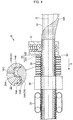
- the porous resin layer 14 is compressed between the inner wall 24A and the pipe body 12, so that the compressively held portion 14A is in tight contact with the covering layer 20, and a projection 14B is engaged between the side walls 24B of the adjacent groove portions 24, therefore the porous resin layer may be easily shortened together with the covering layer 20. Owing to such a configuration, an end of the pipe body 12 can be exposed as depicted in FIG. 8 .
- the thickness HI of the outer walls 22A is set to be less than the thickness H2of the inner walls 24A in the embodiment, the thickness HI may be the same as the thickness H2.
- outer walls 22A has a substantially straight shape in the axial direction S in the embodiment, the outer walls may have an arc shape swelling outward in the radial direction.
- the inner walls 24A may also have an arc shape swelling inward in the radial direction.
- another layer 13 may be disposed between the porous resin layer 14 and the pipe body 12.
- a low friction sheet may be provided to improve the sliding property between the porous resin layer 14 and the pipe body 12 to establish a configuration promoting deformation through improved followability of the porous resin layer 14 and such other layer 13 to the covering layer 20, when an end of the pipe body 12 is to be exposed by shortening and deforming the covering layer 20.
- the porous resin layer 14 is entirely in contact with the outer circumferential surface of the pipe body 12.
- the porous resin layer 14 is compressed between the inner wall 24A and the pipe body 12.
- the compressively held portion 14A is brought into tight contact with the covering layer 20, and the projection 14B is engaged between the side walls 24B of the adjacent groove portions 24.
- a manufacturing apparatus 30 illustrated in Figure 4 can be used for manufacturing the composite pipe 10.
- the manufacturing apparatus 30 includes an extruder 32, a die 34, a corrugation mold 36, a cooling tank 38, and a receiving apparatus 39.
- the right section in Figure 4 is defined as being upstream in the manufacturing flow of the composite pipe 10 in the manufacturing apparatus 30, and the composite pipe is manufactured with the pipe body 12 being transferred from the right to the left.
- the transferring direction is referred to as "manufacturing direction Y".
- the die 34, the corrugation mold 36, the cooling tank 38, and the receiving apparatus 39 are disposed in the listed order in the manufacturing direction Y, and the extruder 32 is disposed upstream relative to the die 34.
- a pipe body 12 wound up in a coil shape, and a sheet-shaped member 14S, which is a porous resin sheet wound up in a roll shape and is to form a porous resin layer 14, are disposed upstream of the die 34.
- the pipe body 12 in a coil shape and the sheet-shaped member 14S in a roll shape are pulled by a receiving apparatus 39 in the manufacturing direction Y, and thus continuously extracted.
- the sheet-shaped member 14S is wound around the entire outer circumferential surface of the pipe body 12 extracted continuously, before the die 34.
- the sheet-shaped member 14S is slackened before the die 34 in order not to allow a tensile force to act, and is inserted into the die 34.
- the outer circumferential surface of the sheet-shaped member 14S wound onto the outer circumferential surface of the pipe body 12 is applied a resin material molten (a molten product of a resin composition for formation of the covering layer 20) cylindrically extruded from the die 34, and a resin layer 20A is formed.
- the resin here used is low-density polyethylene (LDPE) having an MFR of 0.4 or more, whereby the resin material easily enters pores (air bubbles) of the porous resin sheet, thereby resulting in an enhancement in adhesion of the sheet-shaped member 14S and the resin layer 20A.
- LDPE low-density polyethylene
- a corrugation step (step of formation of a bellows shape) is performed in the corrugation mold 36 disposed downstream relative to the die 34.
- the corrugation mold 36 corresponds to, for example, a pair of molds, and all the molds have a semi-arc inner surface.
- Each annular cavity 36A is formed on a portion of the inner circumferential surface of such a mold, corresponding to the ridge portions 22 of the covering layer 20, and each annular inner projection 36B is formed on a portion thereof, corresponding to the groove portions 24, and has a bellows shape.
- Each vent 36C is formed in such a cavity 36A, the vent being formed with having one end in communication with such a cavity 36A and penetrating through each of such corrugation molds 36. Suction in such a cavity 36A is performed from the outside of each of such corrugation molds 36 via the vent 36C.
- Such a pair of corrugation molds 36 approaches to the resin layer 20A from two directions downstream relative to the die 34 and the inner surfaces thereof are brought into contact therewith, and the corrugation molds are transferred together with the pipe body 12 in the manufacturing direction Y with the outer circumferential surface of the tubular extruded product 21 being covered under pushing of the resin layer 20A by the inner projection 36B. Suction from the outside of the corrugation molds 36 is here performed to thereby impart a negative pressure in the cavity 36A. Thus, the resin layer 20A is transferred outward in the radial direction, and a bellows-shaped covering layer 20 along with each of the corrugation molds 36 is formed.
- the repulsive force in the radial direction at the compressively held portion of the porous resin layer 14 is 30 N/cm 2 or less. Therefore, pushing back the resin layer 20A axially outward by the the porous resin layer 14, and pushing out the resin layer 20A into the gap of the contact portion contacting the pair of corrugation molds 36 are suppressed, and generation of burr radially outside the covering layer 20 is inhibited.
- the sheet-shaped member 14S enters the cavity 36A in the protrusion space 23 corresponding to the ridge portions 22 of the covering layer 20, and the projection portions 14B is formed.
- a portion corresponding to the inner walls 24A of the groove portions 24 of the covering layer 20 is not only kept with adhering to the covering layer 20, but also compressed between the pipe body 12 and the inner walls 24A, and the compressively held portion 14A is formed.
- the covering layer 20 is cooled in a cooling tank 38.
- the composite pipe 10 is manufactured.
- the present disclosure provides the following composite pipe.
- a polyisocyanate and a polyol as raw materials were mixed and reacted together with a catalyst, a foaming agent, and a foam stabilizer, and the product was cut to a desired thickness with a cutting machine to yield a polyurethane foam sheet A having a thickness (average thickness in a natural state) of 2.5 mm.
- a manufacturing apparatus having the structure shown in FIG. 4 was prepared.
- a polybutene pipe wound in a form of a coil was loaded as the pipe body 12, and a polyurethane foam sheet B (thickness 3.0 mm) produced by the method described before was loaded as the sheet-shaped member 14S.
- the receiving apparatus 39 was operated to continuously draw out the coiled polybutene pipe and the rolled-up polyurethane foam sheet B (sheet-shaped member 14S), and the polyurethane foam sheet B was wound around the entire outer circumferential surface of the polybutene pipe.
- the polyurethane foam sheet B was slackened before a die 34 and then inserted into the die 34.
- a molten resin material (low density polyethylene (LDPE)) was cylindrically extruded from the die 34 and applied to the outer circumferential surface of the polyurethane foam sheet B to form a resin layer.
- LDPE low density polyethylene
- the corrugation molds 36 are a pair of molds with the same inner surface shape, both of which have a semi-arc inner surface.
- an annular cavity 36A is formed at a part corresponding to each ridge portion of the covering layer to be formed, and an annular inward projection 36B at a part corresponding to each groove portion is formed, such that a bellows shape is formed.
- a vent 36C one end of which is in communication with the cavity 36A through the corrugation mold 36, is formed.
- the resin layer 20A was moved together with the polybutene pipe in a manufacturing direction Y, while the resin layer 20A was pressed by the inward projections 36B, and the inside of cavity 36A was aspirated from the outside of the corrugation mold 36 to a negative pressure.
- the bellows covering layer was formed along the corrugation mold 36.
- the distance between the inner surface of the groove portion 24 of the covering layer and the outer surface of the polybutene pipe (the pipe body), namely the difference between the outer circumferential surface of the pipe body and the radially inner side surface of the inner wall 24A of the covering layer (clearance at the compressively held portion) was 2.0 mm.
- the length L1 in the axial direction S of the ridge portion 22 of the covering layer was 2.1 mm, and the length L2 in the axial direction S of the groove portion 24 was 1.5 mm.
- the thickness of the covering layer was 0.2 mm at the thinnest part, and 0.5 mm at the thickest part.
- the diameter of the covering layer (the diameter of the outermost surface) was 23.5 mm.
- the polyurethane foam sheet B layer (porous resin layer) was entirely in contact with the outer surface of the pipe body.
- a composite pipe was obtained in the same manner as in Example 1, except that the applied polyurethane foam sheet was changed to the one listed in Table 1, and the distance between the inner surface of the groove portion 24 of the covering layer and the outer surface of the polybutene pipe (the pipe body) (clearance at the compressively held portion) was adjusted to the value described in Table 1 below by adjusting the diameter of the covering layer.
Landscapes
- Engineering & Computer Science (AREA)
- General Engineering & Computer Science (AREA)
- Mechanical Engineering (AREA)
- Rigid Pipes And Flexible Pipes (AREA)
- Laminated Bodies (AREA)
Abstract
Description
- The present disclosure relates to a composite pipe having a multilayer structure.
- Heretofore, various pipes, which cover piping in order to protect the piping, have been proposed. For example, Patent Literature 1 discloses a corrugated pipe for a wiring or piping material, through which the wiring or piping material is inserted, and at least the inner side of which is formed of a polyolefin synthetic resin or vinyl chloride resin mixed with a fluorocarbon resin.
- [Patent Literature 1] Japanese Patent Application Laid-Open (
JP-A) No. 2015-48909 - It is conceivable to, in a composite pipe including an interior pipe body and a bellows-shaped covering layer for covering the outer circumferential surface of the pipe body, dispose a porous resin layer as a shock-absorbing layer between the pipe body and the covering layer from the viewpoint of further enhancing in shock-absorbing properties. In such a composite pipe, the covering layer is required to be displaced to expose an end of the interior pipe body when a coupling or the like is connected to an end of the interior pipe body. After the coupling or the like is connected to the end of the pipe body, the covering layer is required to be returned to an initial length to cover the pipe body again.
- However, when the covering layer is exposed and then returned to an initial length, the porous resin layer is subjected to oppositely-directed frictional forces applied from the covering layer located on an outer circumferential surface thereof, which moves in the axial direction of the composite pipe to recover, and the pipe body located on an inner circumferential surface thereof. Thus, the porous resin layer does not follow the moving of the covering layer, and a phenomenon may occur in which the porous resin layer is entangled and partially curled in clusters due to the oppositely-directed frictional forces applied from the outer circumferential surface and the inner circumferential surface thereof. The occurrence of such entanglement may cause the porous resin layer to not return to the initial position in some cases.
- A composite pipe having a pipe body, a bellows-like covering layer covering the pipe body, and a porous resin layer disposed between the pipe body and the covering layer is produced, for example, by applying, onto the outer circumferential surface of the porous resin layer, a molten product of a resin composition for forming a covering layer in a state in which a sheet to be formed into the porous resin layer is wound around the outer circumferential surface of the pipe body, and solidifying the molten product while forming it into a bellows shape. In this case, for forming the molten product of the resin composition for forming a covering layer into a bellows shape, a method is conceivable by which a pair of molds each having a semi-arc inner surface with bellows shape are made to approach the outer circumferential surface of the molten product from two directions to come into contact, and the molten product is solidified to form a bellows shape.
- However, since a force acts on the molten product applied to the outer circumferential surface of the porous resin layer such that the molten product is pushed back outward in the radial direction from the porous resin layer, the molten product may not be fully accommodated inside the pair of molds, but rather pushed out into a contact portion of the pair of molds which the molten product should not normally reach. As a consequence, burr may be generated outside a solidified covering layer. In a case in which there is burr outside the covering layer, the movement of the covering layer for exposing an end of the pipe body is suppressed, and contraction of the covering layer itself becomes difficult. Although providing a step of removing the burr generated outside is also conceivable, this removal step complicates the production of a composite pipe.
- Considering the above situation, an object of the present disclosure is to provide a composite pipe of the embodiment including a pipe body having a tubular shape, a covering layer which has a tubular shape and covers an outer circumferential surface of the pipe body, and a porous resin layer disposed between the pipe body and the covering layer, wherein in the composite pipe, burr radially outside the covering layer is suppressed, and occurrence of entanglement (curl) of the porous resin layer is suppressed, when an end of the covering layer is once shortened and deformed to expose an end of the pipe body, and then the shortened covering layer is elongated to an initial length.
- The above problems are solved by the following disclosure.
- <1> A composite pipe including a pipe body having a tubular shape and including a resin material, a covering layer including a resin material, the covering layer having a tubular shape and covering an outer circumferential surface of the pipe body, the covering layer having a bellow shape with annular ridge portions protruding outwardly in a radial direction and annular groove portions depressed inwardly in the radial direction, the annular ridge portions and the annular groove portions being alternately formed in an axial direction of the pipe body, and the covering layer being shortenable in the axial direction of the pipe body by being guided along the outer circumferential surface of the pipe body, and a porous resin layer disposed between the pipe body and the covering layer, the porous resin layer having compressively held portions that are compressed and held between the groove portions and the pipe body, and the porous resin layer having a repulsive force in a radial direction of from 21 N/cm2 to 30 N/cm2 at the compressively held portions.
- According to an aspect of the present disclosure, there can be provided a composite pipe of the embodiment including a pipe body having a tubular shape, a covering layer which has a tubular shape and covers an outer circumferential surface of the pipe body, and a porous resin layer disposed between the pipe body and the covering layer, wherein in the composite pipe, burr radially outside the covering layer is suppressed, and occurrence of entanglement (curl) of the porous resin layer is suppressed, when an end of the covering layer is once shortened and deformed to expose an end of the pipe body, and then the shortened covering layer is elongated to an initial length.
-
-
Figure 1 is a perspective view illustrating a composite pipe according to an embodiment of the present disclosure. -
Figure 2 is a vertical cross-sectional view illustrating a composite pipe according to an embodiment of the present disclosure. -
Figure 3 is a partially enlarged view of a vertical cross-section of a composite pipe according to an embodiment of the present disclosure. -
Figure 4 is a view illustrating a step of manufacturing the composite pipe of the present disclosure. -
Figure 5 is a vertical cross-sectional view illustrating a state in which an end of a pipe body of a composite pipe according to an embodiment of the present disclosure is exposed. -
Figure 6 is a view illustrating a process in which a covering layer and a porous resin layer in the vertical cross-section portion inFigure 3 are being shortened and deformed. -
Figure 7 is a view illustrating a state in which a covering layer and a porous resin layer in the vertical cross-section portion inFigure 3 are shortened and deformed. -
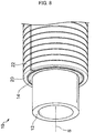
Figure 8 is a perspective view illustrating a state in which an end of a pipe body of a composite pipe according to an embodiment of the present disclosure is exposed. -
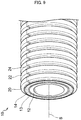
Figure 9 is a perspective view illustrating a composite pipe according to another embodiment of the present disclosure. -
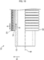
Figure 10 is a vertical cross-sectional view of a composite pipe, for illustrating a force acting on the porous resin layer from the covering layer and a force acting on the porous resin layer from the pipe body when the covering layer is shortened and deformed and then returned to an initial length. -
Figure 11 is a perspective view illustrating a portion of a conventional composite pipe, in which a porous resin layer is entangled and thus partially curled in clusters. - Hereinafter, an embodiment as an example of the composite pipe according to the present disclosure is described in detail appropriately with reference to the drawings. It is meant that constituent components indicated by the same symbol in each drawing are the same constituent components. It is noted that descriptions and symbols overlapped in the embodiment described below may be omitted.
- The "main component" herein refers to a component having the highest content on a mass basis in a mixture, unless particularly noted.
- The composite pipe according to the present disclosure includes a pipe body having a tubular shape, a covering layer which has a tubular shape and covers the outer circumferential surface of the pipe body, and a porous resin layer disposed between the pipe body and the covering layer.
- The pipe body is composed of a resin material, more precisely composed of a resin material containing a resin.
- The covering layer is composed of a resin material, more precisely composed of a resin material containing a resin. It has a bellows shape with annular ridge portions protruding outwardly in a radial direction and annular groove portions depressed inwardly in the radial direction, the annular ridge portions and the annular groove portions being alternately formed in an axial direction of the pipe body, and the covering layer being shortenable in the axial direction of the pipe body by being guided along the outer circumferential surface of the pipe body.
- The porous resin layer has a compressively held portion compressed and held between the groove portions and the pipe body, and the repulsive force in the radial direction at the compressively held portion is from 21 N/cm2 to 30 N/cm2.
- With respect to a composite pipe, when an end of the internal pipe body is to be connected with a coupling or the like, it is required to shorten and displace an end of the covering layer to expose an end of the pipe body, to connect the end of the pipe body with the coupling or the like, and then the shortened covering layer is elongated to an initial length to cover again the pipe body. However, as shown in
FIG. 10 , when the coveringlayer 20 is replaced to the original position after exposing thepipe body 12, the coveringlayer 20 moves in the axial direction to return to the original position, so that a force in the direction of the arrow A from the coveringlayer 20 acts on theporous resin layer 14. Meanwhile, thepipe body 12 is tried to relatively remain in its location against the moving of the coveringlayer 20 in the axial direction, so that a force in the direction of the arrow B from thepipe body 12 acts on theporous resin layer 14. In other words, to theporous resin layer 14, the friction forces in the opposite directions are applied from the covering layer 20 (the outer circumference side) and the pipe body 12 (the inner circumference side) respectively. Therefore, when theporous resin layer 14 cannot fully follow the movement of the coveringlayer 20, a phenomenon in which entanglement of theporous resin layer 14 may take place and part of which may be curled in clusters due to the friction forces in the opposite directions applied from the outer circumference side and the inner circumference side respectively may occur. In this regard,FIG. 11 presents a perspective view showing an area in which entanglement of theporous resin layer 14 occurs and part of which is curled in clusters. In the composite pipe shown inFIG. 11 , entanglement C has occurred at the end of theporous resin layer 14. In this figure showing the location in which the entanglement C has occurred, a state in which the coveringlayer 20 is shortened again to expose the location in which the entanglement C has occurred is illustrated. AlthoughFIG. 11 shows a state in which the entanglement C has occurred at the end of theporous resin layer 14, such entanglement (curl) may occur not at the end of theporous resin layer 14, but on the axially central side (in the axially middle zone) of the porous resin layer. - Meanwhile, in the present disclosure, the repulsive force in the radial direction at the compressively held portion of the porous resin layer is 21 N/cm2 or more.
- By this means, the
porous resin layer 14 is not pressed too much to thepipe body 12 side, and when the end of thepipe body 12 is exposed by shortening and deforming the end of thecovering layer 20, and then thecovering layer 20 is replaced to the original position, theporous resin layer 14 follows well the axial elongating operation of thecovering layer 20, so that a phenomenon in which entangled part of theporous resin layer 14 is curled in clusters may be suppressed. As a result, the exposed end of thepipe body 12 can be well covered again with theporous resin layer 14 and thecovering layer 20. - The lower limit value of the repulsive force in the radial direction at the compressively held portion is preferably 22 N/cm2 or more from the viewpoint of suppressing occurrence of entanglement (curl).
- For producing a composite pipe, a method is conceivable by which the molten product of a resin composition for forming a covering layer is further applied to a sheet to form a porous resin layer wound around the outer circumferential surface of the pipe body, and a pair of molds having a semi-arc inner surface with bellows shape are made to approach the outer circumferential surface of the molten product from two directions to come into contact, and the molten product is solidified to form a bellows shape. However, since a force acts on the applied molten product such that the molten product is pushed back outward in the radial direction from the porous resin layer, and may be pushed out into a contact portion of the pair of molds such that burr may be generated outside the covering layer.
- In contrast, according to the present disclosure, the repulsive force in the radial direction at the compressively held portion of the porous resin layer is 30 N/cm2 or less.
- By this means, the repulsive force acted outward in the radial direction on the applied molten product from the porous resin layer is limited, it is suppressed that the molten product of the resin composition for forming a covering layer is pushed back axially outward from the porous resin layer and is pushed out into the contact portion of the pair of molds, and generation of burr radially outside the covering layer is inhibited. Therefore, it may be inhibited that burr becomes an obstacle to the operation of shortening and shifting the covering layer in order to expose an end of a pipe body, and therefore the shortening operation can be performed easily. In addition, a step of removing burr generated radially outside the covering layer may be omitted so as to avoid complication of the producing process of a composite pipe.
- The upper limit value of the repulsive force in the radial direction at the compressively held portion is preferably 25 N/cm2 or less from the viewpoint of suppression of the burr.
- The range of the repulsive force in the radial direction at the compressively held portion is from 21 N/cm2 to 30 N/cm2, more preferably from 22 N/cm2 to 28 N/cm2, and further preferably from 22 N/cm2 to 25 N/cm2.
- In this regard, the repulsive force in the radial direction at the compressively held portion of the porous resin layer can be determined from a "force vs deflection curve" measured by "6.8 E Method (method for determining compressive deflection coefficient and hysteresis loss rate)" specified in JIS-K 6400-2 (2012). The measurement environment in which the temperature is set at 23°C, and a relative humidity is 45% should be used. The measurement of force vs deflection curve is performed three times in total, and the second result among them is adopted.
- The method of controlling the repulsive force in the radial direction at the compressively held portion of the porous resin layer within the above range is not particularly limited, and examples thereof include a method by which the compression rate of the porous resin layer at the compressively held portion is adjusted, and a method by which the elastic modulus of the porous resin layer is adjusted (such as a method of adjusting an abundance ratio of pores in the porous resin layer (for example, in the case of a foam, a foaming rate), or a method of adjusting the molecular structure of the porous resin (that is, a method of adjusting the molecular structure of a monomer to be used as a raw material for a porous resin, or the cross-linked structure thereof).)
- From the viewpoint of regulating the repulsive force in the radial direction at the compressively held portion of the porous resin layer within the above range, the compression rate of the porous resin layer at the compressively held portion is preferably from 160% to 230%, more preferably from 165% to 220%, and further preferably from 170% to 200%.
- In this regard, the compression rate represents a value of "thickness B of the porous resin layer in the natural state (state in which a force, such as a compressive force or a tensile force is not loaded, the temperature is 23°C, and the relative humidity is 45%)/thickness A of the porous resin layer at the compressively held portion".
- The compression rate at the compressively held portion may be adjusted with the thickness of the porous resin layer in the natural state, and the difference (distance) between the outer circumferential surface of the pipe body and the inner surface in the radial direction of the inner wall of the groove portion of the covering layer.
- A porous resin layer is a layer composed of a resin material (that is, composed of a resin material containing a resin) and having a porous structure. Although there is no particular restriction on the resin in a resin material composing a porous resin layer, among others polyurethane is preferable, and a porous polyurethane layer containing polyurethane as a main component is preferable.
- Although a resin material composing a porous resin layer may be a material composed solely of a resin, it may contain another additive.
- In the composite pipe according to the present disclosure, the density of the porous resin layer is preferably from 12 kg/m3 to 22 kg/m3, and more preferably in a range of from 14 kg/m3 to 20 kg/m3.
- In the composite pipe, an end of the covering layer is required to be shortened and displaced to expose an end of an interior pipe body when a coupling or the like is connected to an end of the pipe body. However, the pipe body cannot be sufficiently exposed in some cases because the porous resin layer does not follow, and remains on the outer surface of the pipe body in the displacement of the covering layer. Meanwhile, in a case in which the porous resin layer has a density of 22 kg/m3 or less, the porous resin layer has proper flexibility and thus the porous resin layer favorably follows the movement of the covering layer when an end of the covering layer is shortened and displaced to expose an end of the pipe body, whereby the porous resin layer less likely to remain on the outer surface of the pipe body. As a result, such an end of the pipe body can be easily exposed.
- In this regard, in a case in which the porous resin layer has a density of 12 kg/m3 or more, the porous resin layer has proper strength and it is inhibited that the porous resin layer is broken and damaged in processing in manufacturing or the like of the composite pipe.
- The density of the porous resin layer can be measured according to the method prescribed in JIS-K7222 (2005). The measurement environment is here an environment of a temperature of 23°C and a relative humidity of 45%.
- The method of controlling the density of the porous resin layer within the above range is not particularly limited, and examples thereof include a method of adjusting the abundance ratio in the porous resin layer (for example, the foaming rate in the case of the foam) and a method of adjusting the molecular structure of the resin (namely, adjusting the molecular structure of a monomer serving as a raw material of the resin, and/or the crosslinked structure thereof).
- In the composite pipe according to the present disclosure, the hysteresis loss of the porous resin layer is preferably 42% or more. Although there is no particular restriction on the upper limit value of the hysteresis loss, it is preferably 80% or less.
- When the composite pipe is produced, a method is conceivable by which, for example, the outer circumferential surface of the pipe body is wound by a sheet serving as the porous resin layer, and is further applied by a molten product of a resin composition for covering layer formation, a pair of molds each having a semi-arc inner surface having a bellows shape are made to approach the outer circumferential surface of the molten product from two directions to come into contact, and the molten product is solidified to form a bellows-shaped. However, the molten product for applying is subjected to application of a force so as to be pushed back from the porous resin layer outward in the radial direction, whereby the molten product may be pushed out onto any contact portion between the pair of molds, thereby causing any burr to occur on the outside of the covering layer. On the contrary, in a case in which the hysteresis loss of the porous resin layer is 42% or more, flattening of the porous resin layer is adjusted to a proper range, it is inhibited that the molten product of a resin composition for covering layer formation is pushed back from the porous resin layer outward in the radial direction and is pushed out onto the contact portion between the pair of molds, and occurring of burr on the outside of the covering layer in the radial direction is inhibited. Thus, obstructing a movement for shortening and displacement of the covering layer to expose an end of the pipe body by any burr is inhibited, and the movement for shortening of the covering layer can be easily performed. A step of removing any burr generated on the outside of the covering layer in the radial direction can be omitted, and complicated manufacturing process of the composite pipe can be avoided.
- The hysteresis loss of the porous resin layer can be measured according to the method prescribed in JIS-K6400-2 (2012). The measurement environment is here an environment of a temperature of 23°C and a relative humidity of 45%. The hysteresis loss is measured three times in total and the second result thereof are adopted.
- The method of controlling the hysteresis loss of the porous resin layer within the above range is not particularly limited, and examples thereof include a method of adjusting the abundance ratio in the porous resin layer (for example, the foaming rate in the case of the foam) and a method of adjusting the molecular structure of the resin (namely, adjusting the molecular structure of a monomer serving as a raw material of the resin, and/or the crosslinked structure thereof).
- Next, a mode for carrying out the composite pipe of the present disclosure is described by way of example based on the drawings.
- A
composite pipe 10 according to the present embodiment, illustrated inFigure 1 , includes apipe body 12, aporous resin layer 14, and acovering layer 20. Meanwhile, the symbol S represents the axis of thepipe body 12, and its axial direction. - The
pipe body 12 has a tubular shape, and is a resin pipe composed of a resin material (that is, composed of a resin material containing a resin). - Examples of the resin in the resin material include polyolefins such as polybutene, polyethylene, crosslinked polyethylene, and polypropylene, and vinyl chloride, and such resins may be used singly, or in combination of two or more kinds thereof. In particular, polybutene is suitably used, the resin preferably includes polybutene as a main component, and, for example, the resin material included in the pipe body more preferably includes 85% by mass or more of polybutene.
- The resin material included in the pipe body may be a material made of only the resin, or may contain other additive(s).
- The
covering layer 20 has a tubular shape, and covers the outer circumferential surfaces of thepipe body 12 and theporous resin layer 14. Theporous resin layer 14 is disposed between thepipe body 12 and thecovering layer 20. - The covering layer is composed of a resin material (that is, composed of a resin material containing a resin). Examples of the resin included in the resin material included in the covering layer include polyolefins such as polybutene, polyethylene, polypropylene, and crosslinked polyethylene, and vinyl chloride, and such resins may be used singly, or in combination of two or more kinds thereof. In particular, low-density polyethylene is suitably used, the resin preferably includes low-density polyethylene as a main component, and, for example, the resin material included in the covering layer more preferably includes 80% by mass or more, still more preferably 90% by mass or more of low-density polyethylene.
- The melt flow rate (MFR) of the resin to be used is preferably 0.4 or more. In a case in which the MFR is 0.4 or more, the resin of the
covering layer 20 can easily enter a porous structure of theporous resin layer 14, thereby resulting in an enhancement in the degree of adhesion of theporous resin layer 14 andgroove portions 24 of thecovering layer 20, described below. - The resin material included in the covering layer may be a material made of only the resin, or may contain other additive(s).
- As illustrated in
Figure 2 , acovering layer 20 has a bellows shape, andannular ridge portions 22 protruding outwardly in a radial direction andannular groove portions 24 depressed inwardly in the radial direction are alternately continuously formed in an axial direction S of apipe body 12. Theridge portions 22 is disposed more outward in a radial direction R, than thegroove portions 24. As illustrated inFigure 3 , in a case in which outermost portions of a bellows-shapedcovering layer 20 in the radial direction are defined asouter walls 22A, and innermost portions thereof in the radial direction are defined asinner walls 24A, an intermediate portion M in the radial direction, between theouter walls 22A and theinner walls 24A is defined as a boundary, the areas outside the boundary in the radial direction are defined asridge portions 22, and the areas inside the boundary in the radial direction are defined as agroove portions 24. - The
ridge portion 22 includes anouter wall 22A extending in the axial direction S andside walls 22B extending from both ends of theouter wall 22A along with the radial direction R. Outer bentportions 22C are formed between theouter wall 22A and theside walls 22B. Thegroove portion 24 includes aninner wall 24A extending in the axial direction S andside walls 24B extending from both ends of theinner wall 24A along with the radial direction R. Inner bentportions 24C are formed between theinner wall 24A and theside walls 24B. - A
protrusion space 23 recessed inside in the radial direction is formed inside theridge portion 22 of thecovering layer 20 in the radial direction.Aprojection portion 14B of aporous resin layer 14 described below is preferably inserted into theprotrusion space 23. - The length L1 of each of the
ridge portions 22 in the axial direction S is preferably set to be longer than the length L2 of each of thegroove portions 24 in the axial direction S, but is not particularly limited. The length L1 is preferably at least 1.2-times the length L2 in order to ensure ease of deformation of theouter walls 22A in shortening and deforming described below. The length L1 is preferably at most 5-times the length L2. In a case in which the length L1 is at most 5-times the length L2, flexibility of acomposite pipe 10 can be kept. In a case in which the length L1 is too long, when thecomposite pipe 10 is provided, contact area of thecomposite pipe 10 with the ground increases, thereby resulting in difficulty in the providing of thecomposite pipe 10. - The
covering layer 20 preferably has a thickness of 0.1 mm or greater at a thinnest portion and a thickness of 0.4 mm or less at a thickest portion in order to shorten thecovering layer 20. A thickness HI of theouter wall 22A is less than a thickness H2 of theinner wall 24A. The thickness HI is preferably at most 0.9-times the thickness H2 in order to ensure ease of deformation of theouter wall 22A in shortening and deforming described below. - A difference in radius ΔR between the outer surfaces of the
ridge portion 22 and thegroove portion 24 is preferably 800% or less of the average thickness of thecovering layer 20. In a case in which the difference in radius ΔR is large, even if the portion along the axial direction S of theridge portion 22 is not deformed, radially outward swelling of thegroove portion 24, or a distorted deformation without mutual approach of theadjacent ridge portions 22 is inhibited when the covering layer is shortened. In a case in which the difference in radius ΔR is 800% or less of the average thickness of thecovering layer 20, making the length, in the axial direction S, of theridge portion 22 longer than the length, in the axial direction, of thegroove portion 24 is effective to inhibit such a situation of deformation. It is especially effective when the difference in radius ΔR is 600% or less of the average thickness of thecovering layer 20. - Although there is no particular restriction on the diameter (the outermost diameter) of the
covering layer 20, it may be for example in a range of from 12.85 mm to 34.25 mm. From the viewpoint of easy control of burr radially outside thecovering layer 20, the larger diameter is preferable. - The
porous resin layer 14 is composed of a resin material (that is, composed of a resin material containing a resin), and has a porous structure. As the resin in the resin material composing the porous resin layer, polyurethane, polystyrene, polyethylene, polypropylene, an ethylene/propylene/diene rubber, a mixture of these resins, or the like may be used, and among them polyurethane is more preferable. A layer which contains a polyurethane as a main component is preferable, and for example polyurethane preferably occupies 80% by mass or more in the components of the porous resin layer, and more preferably occupies 90% by mass or more. In this regard, a resin material composing the porous resin layer may be a material composed solely of a resin, or it may contain another additive. - The abundance ratio of pores in the porous resin layer (for example, in the case of the foam, the forming rate) is preferably from 25/25 mm to 45/25 mm. The abundance ratio can be measured by the method described in Appendix 1 of JIS-K6400-1 (2012).
- The
porous resin layer 14 is disposed between thepipe body 12 and thecovering layer 20. Theporous resin layer 14 is held while being compressed between aninner wall 24A of thegroove portion 24 of thecovering layer 20 and thepipe body 12, thereby forming a compressively heldportion 14A. - With respect to the
porous resin layer 14, the repulsive force in the radial direction at the compressively held portion is from 21 N/cm2 to 30 N/cm2. - The inner circumferential surface of the
porous resin layer 14 is preferably flat, is preferably fully in contact with the outer circumferential surface of thepipe body 12, and covers the outer circumferential surface of thepipe body 12. The "fully in contact with" here means not a need for completely close contact of the entire surface, but substantial contact of the entire surface. Accordingly, for example, in a case in which theporous resin layer 14 is formed with being wound by a sheet-shaped porous resin sheet, a seam portion may be partially separated or a portion wrinkled between thepipe body 12 and thecovering layer 20 may be partially separated. - The
porous resin layer 14 can have, for example, a sheet shape. Theporous resin layer 14 can be produced by, for example, winding a sheet-shaped porous resin sheet that is formed in a belt manner so as to have a width which has substantially the same length as the circumferential length of the outer circumferential surface of thepipe body 12, around thepipe body 12, and also feeding a resin composition for forming thecovering layer 20, to the outer circumferential surface of thereof, and molding the resin composition. - The thickness of the
porous resin layer 14 is equal to or greater than the difference between the outer circumferential surface of thepipe body 12 and the inner surface in the radial direction of theinner wall 24A, in a natural state (a state at a temperature of 23°C and a relative humidity of 45%, in which there acts no force, for example, neither compression nor tension), and the thickness of theporous resin layer 14 is preferably greater than the difference. - The
porous resin layer 14 is thinner in thickness on the compressively heldportion 14A, than that in the natural state, due to compression. Aprojection portion 14B is formed between adjacent, compressively heldportions 14A of theporous resin layer 14. Theprojection portion 14B has a larger diameter than that of the compressively heldportion 14A, and is projected into theprotrusion space 23. The top of theprojection portion 14B (the outermost portion in the radial direction) is preferably separated from theouter wall 22A in theprotrusion space 23. In a case in which theporous resin layer 14 is compressed by theinner walls 24A and thepipe body 12, the compressively heldportions 14A and theprojection portions 14B are alternately continuously formed in the axial direction S, and the outer circumferential surface of theporous resin layer 14 has a wave shape. - The thickness of the
porous resin layer 14 in the natural state is preferably in a range of from 1.5 mm to 4.0 mm, more preferably from 2.0 mm to 3.0 mm from the viewpoint of ease of formation of the compressively heldportions 14A compressed by theinner walls 24A and thepipe body 12. The thickness of theporous resin layer 14 in the natural state is defined as the average value of values obtained by measurement at any 10 points of theporous resin layer 14 taken out from thecomposite pipe 10. - A length, in the axial direction S, of the
porous resin layer 14 extracted from between thepipe body 12 and thecovering layer 20, in the natural state is preferably from 90% to 100% of a length, in the axial direction S, of thecovering layer 20. The reason for this is because in a case in which theporous resin layer 14 is elongated and retained between thepipe body 12 and thecovering layer 20, relative transferring between theporous resin layer 14 and thecovering layer 20 can easily occur, thereby making shortening of theporous resin layer 14 and exposure of an end of the outer circumferential surface of thepipe body 12 can be impossible when thecovering layer 20 is shorten and deformed. The length, in the axial direction S, of theporous resin layer 14 in the natural state, is preferably from 90% to 100% of the length, in the axial direction, of thecovering layer 20, in order to suppress such relative transferring between theporous resin layer 14 and thecovering layer 20. - Next, the action of the
composite pipe 10 of the embodiment is described. - When the
composite pipe 10 according to the embodiment and a coupling are connected, any force in a direction in which thecovering layer 20 is shortened in the axial direction S to expose thepipe body 12 is acted on thecovering layer 20 in the state illustrated inFigure 2 . Thus, the coveringlayer 20 at one end is transferred in a direction in which thepipe body 12 is exposed, as illustrated inFigure 5 . - It is preferable in the
outer wall 22A of theridge portion 22 and theinner wall 24A of thegroove portion 24 that the length L1 is longer than the length L2 in the axial direction S and the thickness HI is less than the thickness H2. Thus, theouter wall 22A is more easily deformed than theinner wall 24A, and is deformed so as to swell outward in the radial direction as illustrated inFigure 6 . Subsequently, the outerbent portion 22C of theridge portion 22 and the innerbent portion 24C of thegroove portion 24 are deformed so that theridge portion 22 approaches to adjacent one, as illustrated inFigure 7 . Thus, the coveringlayer 20 at one end is easily transferred in a direction in which thepipe body 12 is exposed, as illustrated inFigure 5 . Thus, deformation is made so that theouter walls 22A swells out in shortening of thecovering layer 20, and thus swelling of thegroove portions 24 outward in the radial direction and/or distortion deformation due to no approaching of theridge portions 22 to adjacent one can be suppressed even in the presence of more or less variations in the bending angle and the thickness of thecovering layer 20. Thus, being deteriorated of the appearance of thecovering layer 20 shortened can be inhibited. - In the present embodiment, the repulsive force in the radial direction at the compressively held portion of the
porous resin layer 14 is 21 N/cm2 or more. By this means, when the end of thepipe body 12 is exposed by shortening and deforming the end of thecovering layer 20, and then thecovering layer 20 is replaced to the original position, theporous resin layer 14 follows well the axial elongating operation of thecovering layer 20, such that a phenomenon in which entangled part of theporous resin layer 14 is curled in clusters may be suppressed. - The
porous resin layer 14 is compressed between theinner wall 24A and thepipe body 12, so that the compressively heldportion 14A is in tight contact with thecovering layer 20, and aprojection 14B is engaged between theside walls 24B of theadjacent groove portions 24, therefore the porous resin layer may be easily shortened together with thecovering layer 20. Owing to such a configuration, an end of thepipe body 12 can be exposed as depicted inFIG. 8 . - While the thickness HI of the
outer walls 22A is set to be less than the thickness H2of theinner walls 24A in the embodiment, the thickness HI may be the same as the thickness H2. - While the
outer walls 22A has a substantially straight shape in the axial direction S in the embodiment, the outer walls may have an arc shape swelling outward in the radial direction. Theinner walls 24A may also have an arc shape swelling inward in the radial direction. - Further, in the present embodiment, as shown in
FIG. 9 , anotherlayer 13 may be disposed between theporous resin layer 14 and thepipe body 12. For example, a low friction sheet may be provided to improve the sliding property between theporous resin layer 14 and thepipe body 12 to establish a configuration promoting deformation through improved followability of theporous resin layer 14 and suchother layer 13 to thecovering layer 20, when an end of thepipe body 12 is to be exposed by shortening and deforming thecovering layer 20. - Further, in the present embodiment, it is preferable that the
porous resin layer 14 is entirely in contact with the outer circumferential surface of thepipe body 12. By this means, after exposing an end of thepipe body 12 by moving theporous resin layer 14 and thecovering layer 20 relative to thepipe body 12, theporous resin layer 14 and thecovering layer 20 can be easily held at the shortened position by the friction force between the outer circumferential surface of thepipe body 12 and the inner circumferential surface of theporous resin layer 14. - Further, in the present embodiment, the
porous resin layer 14 is compressed between theinner wall 24A and thepipe body 12. By this means, the compressively heldportion 14A is brought into tight contact with thecovering layer 20, and theprojection 14B is engaged between theside walls 24B of theadjacent groove portions 24. This facilitate for theporous resin layer 14 to follow the movement of thecovering layer 20, and theporous resin layer 14 is protected from being left behind on the outer circumferential surface of thepipe body 12, so that the same can be easily shortened with thecovering layer 20. - Next, a method of manufacturing the
composite pipe 10 of the embodiment is described. - For example, a
manufacturing apparatus 30 illustrated inFigure 4 can be used for manufacturing thecomposite pipe 10. Themanufacturing apparatus 30 includes anextruder 32, adie 34, acorrugation mold 36, acooling tank 38, and a receivingapparatus 39. The right section inFigure 4 is defined as being upstream in the manufacturing flow of thecomposite pipe 10 in themanufacturing apparatus 30, and the composite pipe is manufactured with thepipe body 12 being transferred from the right to the left. Hereinafter, the transferring direction is referred to as "manufacturing direction Y". Thedie 34, thecorrugation mold 36, thecooling tank 38, and the receivingapparatus 39 are disposed in the listed order in the manufacturing direction Y, and theextruder 32 is disposed upstream relative to thedie 34. - Although not illustrated, a
pipe body 12 wound up in a coil shape, and a sheet-shapedmember 14S, which is a porous resin sheet wound up in a roll shape and is to form aporous resin layer 14, are disposed upstream of thedie 34. Thepipe body 12 in a coil shape and the sheet-shapedmember 14S in a roll shape are pulled by a receivingapparatus 39 in the manufacturing direction Y, and thus continuously extracted. The sheet-shapedmember 14S is wound around the entire outer circumferential surface of thepipe body 12 extracted continuously, before thedie 34. In this regard, the sheet-shapedmember 14S is slackened before the die 34 in order not to allow a tensile force to act, and is inserted into thedie 34. - The outer circumferential surface of the sheet-shaped
member 14S wound onto the outer circumferential surface of thepipe body 12 is applied a resin material molten (a molten product of a resin composition for formation of the covering layer 20) cylindrically extruded from thedie 34, and aresin layer 20A is formed. The resin here used is low-density polyethylene (LDPE) having an MFR of 0.4 or more, whereby the resin material easily enters pores (air bubbles) of the porous resin sheet, thereby resulting in an enhancement in adhesion of the sheet-shapedmember 14S and theresin layer 20A. - After a tubular
extruded product 21 including thepipe body 12, the sheet-shapedmember 14S, and theresin layer 20A is formed, a corrugation step (step of formation of a bellows shape) is performed in thecorrugation mold 36 disposed downstream relative to thedie 34. Thecorrugation mold 36 corresponds to, for example, a pair of molds, and all the molds have a semi-arc inner surface. Eachannular cavity 36A is formed on a portion of the inner circumferential surface of such a mold, corresponding to theridge portions 22 of thecovering layer 20, and each annularinner projection 36B is formed on a portion thereof, corresponding to thegroove portions 24, and has a bellows shape. Eachvent 36C is formed in such acavity 36A, the vent being formed with having one end in communication with such acavity 36A and penetrating through each ofsuch corrugation molds 36. Suction in such acavity 36A is performed from the outside of each ofsuch corrugation molds 36 via thevent 36C. - Such a pair of
corrugation molds 36 approaches to theresin layer 20A from two directions downstream relative to the die 34 and the inner surfaces thereof are brought into contact therewith, and the corrugation molds are transferred together with thepipe body 12 in the manufacturing direction Y with the outer circumferential surface of the tubularextruded product 21 being covered under pushing of theresin layer 20A by theinner projection 36B. Suction from the outside of thecorrugation molds 36 is here performed to thereby impart a negative pressure in thecavity 36A. Thus, theresin layer 20A is transferred outward in the radial direction, and a bellows-shapedcovering layer 20 along with each of thecorrugation molds 36 is formed. - In this regard, according to the present embodiment, the repulsive force in the radial direction at the compressively held portion of the
porous resin layer 14 is 30 N/cm2 or less. Therefore, pushing back theresin layer 20A axially outward by the theporous resin layer 14, and pushing out theresin layer 20A into the gap of the contact portion contacting the pair ofcorrugation molds 36 are suppressed, and generation of burr radially outside thecovering layer 20 is inhibited. - The sheet-shaped
member 14S enters thecavity 36A in theprotrusion space 23 corresponding to theridge portions 22 of thecovering layer 20, and theprojection portions 14B is formed. A portion corresponding to theinner walls 24A of thegroove portions 24 of thecovering layer 20 is not only kept with adhering to thecovering layer 20, but also compressed between thepipe body 12 and theinner walls 24A, and the compressively heldportion 14A is formed. - After the corrugation step is performed on each of the
corrugation molds 36, the coveringlayer 20 is cooled in acooling tank 38. Thus, thecomposite pipe 10 is manufactured. - As described above, the present disclosure provides the following composite pipe.
- <1> According to the first aspect of the present disclosure, there is provided a composite pipe including a pipe body having a tubular shape and comprising a resin material, a covering layer comprising a resin material, the covering layer having a tubular shape and covering an outer circumferential surface of the pipe body, the covering layer having a bellow shape with annular ridge portions protruding outwardly in a radial direction and annular groove portions depressed inwardly in the radial direction, the annular ridge portions and the annular groove portions being alternately formed in an axial direction of the pipe body, and the covering layer being shortenable in the axial direction of the pipe body by being guided along the outer circumferential surface of the pipe body, and a porous resin layer disposed between the pipe body and the covering layer, the porous resin layer having compressively held portions that are compressed and held between the groove portions and the pipe body, and the porous resin layer having a repulsive force in a radial direction of from 21 N/cm2 to 30 N/cm2 at the compressively held portions.
- <2> According to the second aspect of the present disclosure, there is provided the composite pipe according to the first aspect, wherein the porous resin layer has a compression rate at the compressively held portions of from 160% to 230%.
- <3> According to the third aspect of the present disclosure, there is provided the composite pipe according to the first or second aspect, wherein the porous resin layer is a porous polyurethane layer.
- <4> According to the fourth aspect of the present disclosure, there is provided the composite pipe according to any one of the first to third aspects, wherein the porous resin layer has a density of from 12 kg/m3 to 22 kg/m3.
- <5> According to the fifth aspect of the present disclosure, there is provided the composite pipe according to any one of the first to fourth aspects, wherein the porous resin layer has a hysteresis loss of 42% or more.
- <6> According to a sixth aspect of the present disclosure, there is provided the composite pipe according to any one of the first to fifth aspects, wherein the porous resin layer has a sheet shape and contacts with an entire outer circumferential surface of the pipe body.
- <7> According to a seventh aspect of the present disclosure, there is provided the composite pipe according to any one of the first to sixth aspects, wherein a length, in the axial direction, of the porous resin layer in a natural state is from 90% to 100% of a length, in the axial direction, of the covering layer.
- <8> According to an eighth aspect of the present disclosure, there is provided the composite pipe according to any one of the first to seventh aspects, wherein a length, in the axial direction, of each of the ridge portions is greater than a length, in the axial direction, of each of the groove portions.
- Hereinafter, the present disclosure is further specifically described with reference to Examples, but the present disclosure is not intended to be limited to the following Examples.
- A polyisocyanate and a polyol as raw materials were mixed and reacted together with a catalyst, a foaming agent, and a foam stabilizer, and the product was cut to a desired thickness with a cutting machine to yield a polyurethane foam sheet A having a thickness (average thickness in a natural state) of 2.5 mm.
- Similar to the polyurethane foam sheet (A1), but by changing the thickness at the time of cutting with a cutting machine, a polyurethane foam sheet B with a thickness of 3.0 mm (average thickness in the natural state) was produced.
- Similar to the polyurethane foam sheet (A1), but by changing the thickness at the time of cutting with a cutting machine, a polyurethane foam sheet B with a thickness of 3.5 mm (average thickness in the natural state) was produced.
- Similar to the polyurethane foam sheet (A1), but by changing the thickness at the time of cutting with a cutting machine, a polyurethane foam sheet B with a thickness of 5.0 mm (average thickness in the natural state) was produced.
- A manufacturing apparatus having the structure shown in
FIG. 4 was prepared. A polybutene pipe wound in a form of a coil was loaded as thepipe body 12, and a polyurethane foam sheet B (thickness 3.0 mm) produced by the method described before was loaded as the sheet-shapedmember 14S. The receivingapparatus 39 was operated to continuously draw out the coiled polybutene pipe and the rolled-up polyurethane foam sheet B (sheet-shapedmember 14S), and the polyurethane foam sheet B was wound around the entire outer circumferential surface of the polybutene pipe. The polyurethane foam sheet B was slackened before a die 34 and then inserted into thedie 34. - Next, a molten resin material (low density polyethylene (LDPE)) was cylindrically extruded from the
die 34 and applied to the outer circumferential surface of the polyurethane foam sheet B to form a resin layer. - Then, a pair of
corrugation molds 36 disposed on the downstream side of the die 34 were made to approach the resin layer from two directions to bring the inner surfaces into contact. Thecorrugation molds 36 are a pair of molds with the same inner surface shape, both of which have a semi-arc inner surface. On the inner circumferential surface, anannular cavity 36A is formed at a part corresponding to each ridge portion of the covering layer to be formed, and an annularinward projection 36B at a part corresponding to each groove portion is formed, such that a bellows shape is formed. In each of thecavities 36A, avent 36C, one end of which is in communication with thecavity 36A through thecorrugation mold 36, is formed. Theresin layer 20A was moved together with the polybutene pipe in a manufacturing direction Y, while theresin layer 20A was pressed by theinward projections 36B, and the inside ofcavity 36A was aspirated from the outside of thecorrugation mold 36 to a negative pressure. Thus, the bellows covering layer was formed along thecorrugation mold 36. - Then, by cooling in a
cooling tank 38, a composite pipe was obtained. - The distance between the inner surface of the
groove portion 24 of the covering layer and the outer surface of the polybutene pipe (the pipe body), namely the difference between the outer circumferential surface of the pipe body and the radially inner side surface of theinner wall 24A of the covering layer (clearance at the compressively held portion) was 2.0 mm. - In the obtained composite pipe, the length L1 in the axial direction S of the
ridge portion 22 of the covering layer was 2.1 mm, and the length L2 in the axial direction S of thegroove portion 24 was 1.5 mm. - The thickness of the covering layer was 0.2 mm at the thinnest part, and 0.5 mm at the thickest part.
- The difference in radius ΔR between the outer surface at the
ridge portion 22 and the same at thegroove portion 24 was 88.9%. - The diameter of the covering layer (the diameter of the outermost surface) was 23.5 mm.
- The polyurethane foam sheet B layer (porous resin layer) was entirely in contact with the outer surface of the pipe body.
- A composite pipe was obtained in the same manner as in Example 1, except that the applied polyurethane foam sheet was changed to the one listed in Table 1, and the distance between the inner surface of the
groove portion 24 of the covering layer and the outer surface of the polybutene pipe (the pipe body) (clearance at the compressively held portion) was adjusted to the value described in Table 1 below by adjusting the diameter of the covering layer. - It was visually confirmed whether or not the resin material for covering layer formation entered the contact portion between the pair of corrugation molds, thereby causing the occurrence of burr on the outside of the covering layer in the radial direction, in production of the composite pipe. The results are shown in Table 1 below.
- An end of the covering layer was drawn by 30 mm to cause shortening and deforming for exposing an end of the polybutene pipe (the pipe body), and then a elongating operation to replace the covering layer again to the original position was performed. In so doing, it was examined visually whether the polyurethane foam sheet layer (porous resin layer) could not follow the operation of elongating the covering layer, and entanglement occurred to cause a phenomenon of curling partially in clusters, or the polyurethane foam sheet layer followed the operation of elongating the covering layer, so that entanglement did not occur and the polyurethane foam sheet layer was replaced to the original position. The results are shown in the following Table 1.
[Table 1] Clearance at compressively held portion (A) [mm] Polyurethane foam sheet Sheet thickness (B) [mm] Compression Rate (B)/(A) [%] Repulsive force at compressively held portion [N/cm2] Evaluation Comparative Example 1 2.0 D 5.0 250 31.5 Burr generated Example 1 1.5 B 3.0 200 25.0 No problem Example 2 2.0 C 3.5 175 22.5 No problem Example 3 1.5 A 2.5 167 21.5 No problem Comparative Example 2 2.0 B 3.0 150 20.3 Entanglement occurred Comparative Example 3 2.0 A 2.5 125 19.3 Entanglement occurred - In Comparative Example 1 in which the repulsive force at the compressively held portion exceeded 30 N/cm2, generation of burr was recognized, but in Examples 1 to 3 in which the same was 30 N/cm2 or less, generation of burr was not recognized.
- When different values of the repulsive force at the compressively held portion were realized by adjusting the clearance (A) at the compressively held portion and the thickness (B) of the polyurethane foam sheet, and similar tests as above were carried out, it was confirmed that separated by the repulsive force at the compressively held portion of 30 N/cm2, in the higher region burr was generated, but in the region not higher than 30 N/cm2, burr did not appear.
- Also, in Comparative Examples 2 and 3 in which the repulsive force at the compressively held portion was less than 21 N/cm2, occurrence of entanglement (phenomenon of curl in clusters) was recognized, but in Examples 1 to 3 in which the repulsive force was 21 N/cm2 or more, occurrence of entanglement was not recognized.
- When different values of the repulsive force at the compressively held portion were realized by adjusting the clearance (A) at the compressively held portion and the thickness (B) of the polyurethane foam sheet, and similar tests as above were carried out, it was confirmed that separated by the repulsive force at the compressively held portion of 21 N/cm2, in the lower region entanglement occurred, but in the region not lower than 21 N/cm2, entanglement did not occur.
- The disclosure of Japanese Patent Application No.
2016-251953 - All documents, patent applications, and technical standards described herein are herein incorporated by reference, as if each individual document, patent application, and technical standard were specifically and individually indicated to be incorporated by reference.
Claims (8)
- A composite pipe comprising:a pipe body having a tubular shape and comprising a resin material;a covering layer comprising a resin material, the covering layer having a tubular shape and covering an outer circumferential surface of the pipe body, the covering layer having a bellow shape with annular ridge portions protruding outwardly in a radial direction, and annular groove portions depressed inwardly in the radial direction, the annular ridge portions and the annular groove portions being alternately formed in an axial direction of the pipe body, and the covering layer being shortenable in the axial direction of the pipe body by being guided along the outer circumferential surface of the pipe body, anda porous resin layer disposed between the pipe body and the covering layer, the porous resin layer having compressively held portions that are compressed and held between the groove portions and the pipe body, and the porous resin layer having a repulsive force in a radial direction of from 21 N/cm2 to 30 N/cm2 at the compressively held portions.
- The composite pipe according to claim 1, wherein the porous resin layer has a compression rate at the compressively held portions of from 160% to 230%.
- The composite pipe according to claim 1 or 2, wherein the porous resin layer is a porous polyurethane layer.
- The composite pipe according to any one of claims 1 to 3, wherein the porous resin layer has a density of from 12 kg/m3 to 22 kg/m3.
- The composite pipe according to any one of claims 1 to 4, wherein the porous resin layer has a hysteresis loss of 42% or more.
- The composite pipe according to any one of claims 1 to 5, wherein the porous resin layer has a sheet shape and contacts with an entire outer circumferential surface of the pipe body.
- The composite pipe according to any one of claims 1 to 6, wherein a length, in the axial direction, of the porous resin layer in a natural state is from 90% to 100% of a length, in the axial direction, of the covering layer.
- The composite pipe according to any one of claims 1 to 7, wherein a length, in the axial direction, of each of the ridge portions is greater than a length, in the axial direction, of each of the groove portions.
Applications Claiming Priority (2)
| Application Number | Priority Date | Filing Date | Title |
|---|---|---|---|
| JP2016251953A JP6820196B2 (en) | 2016-12-26 | 2016-12-26 | Composite pipe |
| PCT/JP2017/045835 WO2018123781A1 (en) | 2016-12-26 | 2017-12-20 | Composite tube |
Publications (2)
| Publication Number | Publication Date |
|---|---|
| EP3561357A1 true EP3561357A1 (en) | 2019-10-30 |
| EP3561357A4 EP3561357A4 (en) | 2019-12-18 |
Family
ID=62710530
Family Applications (1)
| Application Number | Title | Priority Date | Filing Date |
|---|---|---|---|
| EP17888373.2A Withdrawn EP3561357A4 (en) | 2016-12-26 | 2017-12-20 | Composite tube |
Country Status (5)
| Country | Link |
|---|---|
| EP (1) | EP3561357A4 (en) |
| JP (1) | JP6820196B2 (en) |
| CN (1) | CN110114604B (en) |
| TW (1) | TWI725271B (en) |
| WO (1) | WO2018123781A1 (en) |
Families Citing this family (1)
| Publication number | Priority date | Publication date | Assignee | Title |
|---|---|---|---|---|
| JP7376277B2 (en) * | 2019-08-13 | 2023-11-08 | 未来工業株式会社 | Corrugated double pipe and water pipe equipment |
Family Cites Families (24)
| Publication number | Priority date | Publication date | Assignee | Title |
|---|---|---|---|---|
| JPS61235416A (en) * | 1985-04-11 | 1986-10-20 | Achilles Corp | Vibration-proof foam of improved heat-sensitivity |
| JPS62290713A (en) * | 1986-06-09 | 1987-12-17 | Dai Ichi Kogyo Seiyaku Co Ltd | Soundproof damping material |
| JPH0257790A (en) * | 1988-08-18 | 1990-02-27 | Toyo Densen Kk | Heat-insulated pipe and manufacture thereof |
| GB8907113D0 (en) * | 1989-03-29 | 1989-05-10 | Tift Limited | Coupling arrangements |
| DE4128654C2 (en) * | 1991-08-29 | 1995-05-18 | Wolfgang Mayer | Multi-layer plastic conduit and process for its manufacture |
| JPH08239500A (en) * | 1995-02-28 | 1996-09-17 | Nitto Denko Corp | Anti-vibration material |
| JPH11503217A (en) * | 1995-04-03 | 1999-03-23 | ウポノール・ベー・ブイ | Method of manufacturing corrugated tube and corrugated tube manufactured by this method |
| JPH09210291A (en) * | 1996-02-05 | 1997-08-12 | Furukawa Electric Co Ltd:The | Adiabatic tube |
| JP4557388B2 (en) * | 2000-07-18 | 2010-10-06 | 因幡電機産業株式会社 | Method for manufacturing fluid transport pipe with protective pipe |
| JP4516680B2 (en) * | 2000-09-28 | 2010-08-04 | 株式会社パイオラックス | Corrugated tube |
| CN2519095Y (en) * | 2001-12-24 | 2002-10-30 | 靖江市东亚通风空调制造有限公司 | Double-face aluminium foil composite glass cloth noise-absorbing hose |
| JP4190923B2 (en) * | 2002-05-24 | 2008-12-03 | 古河電気工業株式会社 | Stretch corrugated sheath and piping structure for water supply and hot water supply piping materials |
| AU2003261920A1 (en) * | 2002-09-06 | 2004-03-29 | Ork Corporation | Metal bellows tube, method of producing the same, and flexible tube for high-pressure fluid |
| AU2003280235A1 (en) * | 2002-10-31 | 2004-05-25 | Plastiflex Belgium | Tubular body having isolation layer of foamed plastic and method for producing same |
| JP4201638B2 (en) * | 2003-04-28 | 2008-12-24 | 株式会社三洋化成 | Corrugated pipe manufacturing method and corrugated pipe manufactured by the manufacturing method |
| TW200635830A (en) * | 2004-12-29 | 2006-10-16 | Hunter Paine Entpr Llc | Composite structural material and method of making the same |
| JP4896607B2 (en) * | 2006-07-07 | 2012-03-14 | 株式会社イノアックコーポレーション | Soft polyurethane foam for hot press molding and method for producing the same |
| FI20085395A0 (en) * | 2008-04-30 | 2008-04-30 | Uponor Innovation Ab | ventilation holes |
| JP5847403B2 (en) * | 2011-03-01 | 2016-01-20 | 株式会社ブリヂストン | Manufacturing method of composite pipe |
| JP2013231490A (en) * | 2012-05-01 | 2013-11-14 | Bridgestone Corp | Composite pipe, and method for manufacturing the same |
| TWM447448U (en) * | 2012-10-11 | 2013-02-21 | Super Flex Entpr Co Ltd | Joint device |
| JP2015048909A (en) | 2013-09-02 | 2015-03-16 | 未来工業株式会社 | Corrugated pipe for wiring and piping materials |
| JP6300315B2 (en) * | 2014-03-31 | 2018-03-28 | 住友電気工業株式会社 | Fuel cell current collector and fuel cell |
| JP7197356B2 (en) * | 2016-06-09 | 2022-12-27 | 株式会社ブリヂストン | Composite pipe |
-
2016
- 2016-12-26 JP JP2016251953A patent/JP6820196B2/en active Active
-
2017
- 2017-12-20 CN CN201780080588.8A patent/CN110114604B/en active Active
- 2017-12-20 WO PCT/JP2017/045835 patent/WO2018123781A1/en not_active Ceased
- 2017-12-20 EP EP17888373.2A patent/EP3561357A4/en not_active Withdrawn
- 2017-12-21 TW TW106145133A patent/TWI725271B/en active
Also Published As
| Publication number | Publication date |
|---|---|
| EP3561357A4 (en) | 2019-12-18 |
| JP6820196B2 (en) | 2021-01-27 |
| JP2018105406A (en) | 2018-07-05 |
| WO2018123781A1 (en) | 2018-07-05 |
| CN110114604B (en) | 2021-03-05 |
| CN110114604A (en) | 2019-08-09 |
| TW201837356A (en) | 2018-10-16 |
| TWI725271B (en) | 2021-04-21 |
Similar Documents
| Publication | Publication Date | Title |
|---|---|---|
| JP7197356B2 (en) | Composite pipe | |
| EP3561355A1 (en) | Composite pipe and method for manufacturing composite pipe | |
| EP3561356A1 (en) | Composite tube | |
| US7891383B2 (en) | Ringed tubular sheath and device for making such a sheath | |
| JP5811145B2 (en) | coaxial cable | |
| JP6217159B2 (en) | duct | |
| EP3561357A1 (en) | Composite tube | |
| EP3575657A1 (en) | Composite tube | |
| CN108215236B (en) | Method for producing extrusion molded product for automobile | |
| JP7719661B2 (en) | Cladding pipes and composite pipes | |
| JP7737841B2 (en) | Cladding pipes and composite pipes | |
| JP4842580B2 (en) | Thermoplastic resin hollow foam blow molded body | |
| TW202103911A (en) | Composite pipe and method for manufacturing composite pipe | |
| JP2023142260A (en) | composite pipe | |
| JP2020094637A (en) | Composite tube and manufacturing method of composite tube | |
| JP2010228478A (en) | Glass run and method for producing the same | |
| JP2022108565A (en) | Composite pipe | |
| JP2021070271A (en) | Molded body and its manufacturing method |
Legal Events
| Date | Code | Title | Description |
|---|---|---|---|
| PUAI | Public reference made under article 153(3) epc to a published international application that has entered the european phase |
Free format text: ORIGINAL CODE: 0009012 |
|
| 17P | Request for examination filed |
Effective date: 20190628 |
|
| AK | Designated contracting states |
Kind code of ref document: A1 Designated state(s): AL AT BE BG CH CY CZ DE DK EE ES FI FR GB GR HR HU IE IS IT LI LT LU LV MC MK MT NL NO PL PT RO RS SE SI SK SM TR |
|
| AX | Request for extension of the european patent |
Extension state: BA ME |
|
| A4 | Supplementary search report drawn up and despatched |
Effective date: 20191115 |
|
| RIC1 | Information provided on ipc code assigned before grant |
Ipc: B32B 3/30 20060101ALI20191108BHEP Ipc: B32B 1/08 20060101AFI20191108BHEP Ipc: F16L 9/12 20060101ALI20191108BHEP Ipc: B32B 3/28 20060101ALI20191108BHEP Ipc: B32B 5/18 20060101ALI20191108BHEP |
|
| DAV | Request for validation of the european patent (deleted) | ||
| DAX | Request for extension of the european patent (deleted) | ||
| STAA | Information on the status of an ep patent application or granted ep patent |
Free format text: STATUS: THE APPLICATION IS DEEMED TO BE WITHDRAWN |
|
| 18D | Application deemed to be withdrawn |
Effective date: 20200616 |