EP3561341A1 - Sealing system for food applications - Google Patents
Sealing system for food applications Download PDFInfo
- Publication number
- EP3561341A1 EP3561341A1 EP19169190.6A EP19169190A EP3561341A1 EP 3561341 A1 EP3561341 A1 EP 3561341A1 EP 19169190 A EP19169190 A EP 19169190A EP 3561341 A1 EP3561341 A1 EP 3561341A1
- Authority
- EP
- European Patent Office
- Prior art keywords
- rubber
- holes
- rubber profile
- housing element
- profile
- Prior art date
- Legal status (The legal status is an assumption and is not a legal conclusion. Google has not performed a legal analysis and makes no representation as to the accuracy of the status listed.)
- Granted
Links
Images


Classifications
-
- F—MECHANICAL ENGINEERING; LIGHTING; HEATING; WEAPONS; BLASTING
- F16—ENGINEERING ELEMENTS AND UNITS; GENERAL MEASURES FOR PRODUCING AND MAINTAINING EFFECTIVE FUNCTIONING OF MACHINES OR INSTALLATIONS; THERMAL INSULATION IN GENERAL
- F16J—PISTONS; CYLINDERS; SEALINGS
- F16J15/00—Sealings
-
- F—MECHANICAL ENGINEERING; LIGHTING; HEATING; WEAPONS; BLASTING
- F16—ENGINEERING ELEMENTS AND UNITS; GENERAL MEASURES FOR PRODUCING AND MAINTAINING EFFECTIVE FUNCTIONING OF MACHINES OR INSTALLATIONS; THERMAL INSULATION IN GENERAL
- F16J—PISTONS; CYLINDERS; SEALINGS
- F16J15/00—Sealings
- F16J15/02—Sealings between relatively-stationary surfaces
- F16J15/06—Sealings between relatively-stationary surfaces with solid packing compressed between sealing surfaces
- F16J15/10—Sealings between relatively-stationary surfaces with solid packing compressed between sealing surfaces with non-metallic packing
- F16J15/104—Sealings between relatively-stationary surfaces with solid packing compressed between sealing surfaces with non-metallic packing characterised by structure
- F16J15/106—Sealings between relatively-stationary surfaces with solid packing compressed between sealing surfaces with non-metallic packing characterised by structure homogeneous
-
- B—PERFORMING OPERATIONS; TRANSPORTING
- B67—OPENING, CLOSING OR CLEANING BOTTLES, JARS OR SIMILAR CONTAINERS; LIQUID HANDLING
- B67B—APPLYING CLOSURE MEMBERS TO BOTTLES JARS, OR SIMILAR CONTAINERS; OPENING CLOSED CONTAINERS
- B67B3/00—Closing bottles, jars or similar containers by applying caps
- B67B3/02—Closing bottles, jars or similar containers by applying caps by applying flanged caps, e.g. crown caps, and securing by deformation of flanges
- B67B3/026—Closing bottles, jars or similar containers by applying caps by applying flanged caps, e.g. crown caps, and securing by deformation of flanges the caps being made of thermoplastic material
-
- A—HUMAN NECESSITIES
- A23—FOODS OR FOODSTUFFS; TREATMENT THEREOF, NOT COVERED BY OTHER CLASSES
- A23B—PRESERVATION OF FOODS, FOODSTUFFS OR NON-ALCOHOLIC BEVERAGES; CHEMICAL RIPENING OF FRUIT OR VEGETABLES
- A23B2/00—Preservation of foods or foodstuffs, in general
- A23B2/001—Details of apparatus, e.g. pressure feed valves or for transport, or loading or unloading manipulation
-
- B—PERFORMING OPERATIONS; TRANSPORTING
- B65—CONVEYING; PACKING; STORING; HANDLING THIN OR FILAMENTARY MATERIAL
- B65B—MACHINES, APPARATUS OR DEVICES FOR, OR METHODS OF, PACKAGING ARTICLES OR MATERIALS; UNPACKING
- B65B7/00—Closing containers or receptacles after filling
- B65B7/16—Closing semi-rigid or rigid containers or receptacles not deformed by, or not taking-up shape of, contents, e.g. boxes or cartons
- B65B7/28—Closing semi-rigid or rigid containers or receptacles not deformed by, or not taking-up shape of, contents, e.g. boxes or cartons by applying separate preformed closures, e.g. lids, covers
- B65B7/2842—Securing closures on containers
-
- B—PERFORMING OPERATIONS; TRANSPORTING
- B65—CONVEYING; PACKING; STORING; HANDLING THIN OR FILAMENTARY MATERIAL
- B65D—CONTAINERS FOR STORAGE OR TRANSPORT OF ARTICLES OR MATERIALS, e.g. BAGS, BARRELS, BOTTLES, BOXES, CANS, CARTONS, CRATES, DRUMS, JARS, TANKS, HOPPERS, FORWARDING CONTAINERS; ACCESSORIES, CLOSURES, OR FITTINGS THEREFOR; PACKAGING ELEMENTS; PACKAGES
- B65D39/00—Closures arranged within necks or pouring openings or in discharge apertures, e.g. stoppers
- B65D39/0005—Closures arranged within necks or pouring openings or in discharge apertures, e.g. stoppers made in one piece
- B65D39/0029—Plastic closures other than those covered by groups B65D39/0011 - B65D39/0023
-
- B—PERFORMING OPERATIONS; TRANSPORTING
- B65—CONVEYING; PACKING; STORING; HANDLING THIN OR FILAMENTARY MATERIAL
- B65D—CONTAINERS FOR STORAGE OR TRANSPORT OF ARTICLES OR MATERIALS, e.g. BAGS, BARRELS, BOTTLES, BOXES, CANS, CARTONS, CRATES, DRUMS, JARS, TANKS, HOPPERS, FORWARDING CONTAINERS; ACCESSORIES, CLOSURES, OR FITTINGS THEREFOR; PACKAGING ELEMENTS; PACKAGES
- B65D39/00—Closures arranged within necks or pouring openings or in discharge apertures, e.g. stoppers
- B65D39/02—Disc closures
-
- B—PERFORMING OPERATIONS; TRANSPORTING
- B65—CONVEYING; PACKING; STORING; HANDLING THIN OR FILAMENTARY MATERIAL
- B65D—CONTAINERS FOR STORAGE OR TRANSPORT OF ARTICLES OR MATERIALS, e.g. BAGS, BARRELS, BOTTLES, BOXES, CANS, CARTONS, CRATES, DRUMS, JARS, TANKS, HOPPERS, FORWARDING CONTAINERS; ACCESSORIES, CLOSURES, OR FITTINGS THEREFOR; PACKAGING ELEMENTS; PACKAGES
- B65D53/00—Sealing or packing elements; Sealings formed by liquid or plastics material
- B65D53/06—Sealings formed by liquid or plastic material
-
- F—MECHANICAL ENGINEERING; LIGHTING; HEATING; WEAPONS; BLASTING
- F16—ENGINEERING ELEMENTS AND UNITS; GENERAL MEASURES FOR PRODUCING AND MAINTAINING EFFECTIVE FUNCTIONING OF MACHINES OR INSTALLATIONS; THERMAL INSULATION IN GENERAL
- F16J—PISTONS; CYLINDERS; SEALINGS
- F16J15/00—Sealings
- F16J15/02—Sealings between relatively-stationary surfaces
- F16J15/021—Sealings between relatively-stationary surfaces with elastic packing
Definitions
- the present invention relates to a sealing system for food applications, particularly a system for sealing between mechanical components clamped to a machine frame. More particularly, the shape that has been developed makes it possible to avoid cracks in the rubber of the seal, on the outer perimeter of the clamped element, thus preventing the formation of bacteria traps.
- EHEDG European Hygienic Engineering and Design Group
- the EHEDG working group has suggested a shape of the seal to be placed along the whole base perimeter of the housing element.
- One object of the present invention is to provide a sealing system for food applications, for sealing between mechanical components clamped to a machine frame.
- the shape that has been developed makes it possible to avoid cracks in the rubber of the seal on the outer perimeter of the clamped element, thus preventing the formation of bacteria traps.
- the object of the present invention is achieved by using a special rubber profile which is not constant along the whole perimeter of the housing element, by defining the most stressed areas for each embodiment of the invention and consequently the cross section of the rubber, and implementing a transition between two different rubber section profiles.
- housing elements forming part of the sealing system according to the invention are described below purely by way of example. These housing elements are used in food applications for being clamped against a machine frame and, together with an innovative rubber seal, shape the sealing system according to the present invention.
- the idea for a solution is therefore that of implementing a special rubber profile which is not constant along the whole perimeter of the housing element, by defining the most stressed areas for each embodiment of the invention and consequently the cross section of the rubber, and implementing a transition between two different rubber section profiles.
- a first rubber profile with a larger cross section has been designed for implementation around the areas of the bolts, that is to say the areas that are much more stressed.
- the second profile, with a smaller cross section, corresponding to the specifications of the aforesaid guidelines, has been retained throughout the remaining perimeter, to provide the same result, in terms of hygiene, in a less stressed area.
- the profile with the larger cross section makes it possible to produce deformations of the rubber having the same extent as the deformations produced in the less stressed areas, although the rubber profile has a smaller cross section in these areas.
- the principle of proportionality between the tensors of tension and the tensors of deformation of the material is used to produce virtually uniform deformations along the whole perimeter of the housing element.
- Theoretical considerations and experimental evidence have confirmed that the ratio between the two cross sections should preferably be between 1.25 and 1.8.
- the sealing system is preferably made from a rubber having a hardness close to a value of 70 Shore A. This value was determined by conducting experimental tests of resistance to the ingress of water and detergent, using pressure washing.
- the positioning of the transitions was modified to adapt to the specific characteristics of the shape of the housing.
- the sealing system comprises a housing element which is a three-bolt flanged element 10, provided, precisely, with three holes 11 for bolts for clamping to the frame of a machine which is of a known type and is therefore not shown.
- the three-bolt flanged element 10 comprises a body 12.
- the sealing system further comprises a rubber seal 13 placed along the base of the three-bolt flanged element 10.
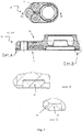
- the first portion 14 of the rubber profile is constant and smaller than the second portion 15 of the rubber profile located adjacent to the holes 11 (detail A of Fig. 1 ).
- the ratio between the thicknesses of the second portion 15 and the first portion 14 is preferably between 1.25 and 1.8. Additionally, as it becomes more distant from the area of the holes, the rubber profile assumes a transitional cross section 16, decreasing as the distance from the area of the holes increases.
- the sealing system comprises a housing element which is a square flanged element 20, provided with four holes 21 for bolts for clamping to the frame of a machine which is of a known type and is therefore not shown.
- the square flanged element 20 comprises a body 22.
- the sealing system further comprises a rubber seal 23 placed along the base of the square flanged element 20.
- the first portion 24 of the rubber profile is constant and smaller than the second portion 25 of the rubber profile located adjacent to the holes 21 (detail A of Fig. 2 ).
- the ratio between the thicknesses of the second portion 25 and the first portion 24 is preferably between 1.25 and 1.8. Additionally, as it becomes more distant from the area of the holes, the rubber profile assumes a transitional cross section 26, decreasing as the distance from the area of the holes increases.
- the sealing system comprises a housing element which is an oval flanged element 30, provided with two holes 31 for bolts for clamping to the frame of a machine which is of a known type and is therefore not shown.
- the oval flanged element 30 comprises a body 32.
- the sealing system further comprises a rubber seal 33 placed along the base of the oval flanged element 30.
- the first portion 34 of the rubber profile is constant and smaller than the second portion 35 of the rubber profile located adjacent to the holes 31 (detail A of Fig. 3 ).
- the ratio between the thicknesses of the second portion 35 and the first portion 34 is preferably between 1.25 and 1.8. Additionally, as it becomes more distant from the area of the holes, the rubber profile assumes a transitional cross section 36, decreasing as the distance from the area of the holes increases.
- the sealing system comprises a housing element which is an upright support element 40, provided with two holes 41 for bolts for clamping to the frame of a machine which is of a known type and is therefore not shown.
- the upright support element 40 comprises a body 42.
- the sealing system further comprises a rubber seal 43 placed along the base of the upright support element 40.
- the first portion 44 of the rubber profile is constant and smaller than the second portion 45 of the rubber profile located adjacent to the holes 41 (detail A of Fig. 4 ).
- the ratio between the thicknesses of the second portion 45 and the first portion 44 is preferably between 1.25 and 1.8.
- the sealing system comprises a housing element which is an upright support element 50, provided with two holes 51 for bolts for clamping to the frame of a machine which is of a known type and is therefore not shown.
- the short-base upright support element 50 comprises a body 52.
- the sealing system further comprises a rubber seal 53 placed along the base of the short-base upright support element 50.
- the first portion 54 of the rubber profile is constant and smaller than the second portion 55 of the rubber profile located adjacent to the holes 51 (detail A of Fig. 5 ).
- the ratio between the thicknesses of the second portion 55 and the first portion 54 is preferably between 1.25 and 1.8. Additionally, as it becomes more distant from the area of the holes, the rubber profile assumes a transitional cross section 56, decreasing as the distance from the area of the holes increases.
Landscapes
- Engineering & Computer Science (AREA)
- Mechanical Engineering (AREA)
- General Engineering & Computer Science (AREA)
- Life Sciences & Earth Sciences (AREA)
- Wood Science & Technology (AREA)
- Zoology (AREA)
- Chemical & Material Sciences (AREA)
- Food Science & Technology (AREA)
- Polymers & Plastics (AREA)
- Gasket Seals (AREA)
- General Preparation And Processing Of Foods (AREA)
Abstract
Description
- The present invention relates to a sealing system for food applications, particularly a system for sealing between mechanical components clamped to a machine frame. More particularly, the shape that has been developed makes it possible to avoid cracks in the rubber of the seal, on the outer perimeter of the clamped element, thus preventing the formation of bacteria traps.
- As is known, in the food and beverages (known simply as F&B, from the English "Food and Beverages") industry, there is increasing interest in the development of new machinery and designs for machinery intended to improve the safety and quality of food. One of the guidelines written by an engineering design group called the European Hygienic Engineering and Design Group (EHEDG) shows how the conventional O-ring or rubber seal commonly used on the market is a risk in the food sector, because of the possibility of creating cracks or small cavities which are completely impossible to clean, and which consequently allow bacterial growth inside them.
- At the present time, in the range of F&B products for Y-type pads, neither the present applicant nor other competitors in the F&B field offer solutions for effective sealing between the base of a housing element clamped against the frame of a machine. The only "palliative" used on the market at present is that of using a composite and completely filled base of the element, instead of using a version having one or more cavities. Clearly, this cannot be considered a solution, since the cost is prohibitive.
- Indeed it is not a simple matter to develop a rubber sealing profile for use on all the shapes of housing elements offered in the range of products for food use.
- To provide a sealing solution that avoids the creation of bacteria traps between the housing element and the machine frame, the EHEDG working group has suggested a shape of the seal to be placed along the whole base perimeter of the housing element.
- This solution has also proven to be unsatisfactory. Inspection of the initial samples of the housing elements has revealed that the rubber did not behave as expected. Indeed, the rubber was deformed in a differential way, and therefore did not succeed in avoiding the creation of bacteria traps in the area of the clamping bolts.
- Consequently there is a need to design a sealing system for food applications that is free of the aforesaid drawbacks. In particular, there is a need to reduce the differential deformation of the sealing system, making it virtually independent of the load conditions.
- One object of the present invention is to provide a sealing system for food applications, for sealing between mechanical components clamped to a machine frame. In particular, the shape that has been developed makes it possible to avoid cracks in the rubber of the seal on the outer perimeter of the clamped element, thus preventing the formation of bacteria traps.
- The object of the present invention is achieved by using a special rubber profile which is not constant along the whole perimeter of the housing element, by defining the most stressed areas for each embodiment of the invention and consequently the cross section of the rubber, and implementing a transition between two different rubber section profiles.
- Therefore, according to the present invention, a description is given of a sealing system for food applications, having the characteristics stated in the independent claim attached to the present description.
- Further preferred and/or particularly advantageous embodiments of the invention are described according to the characteristics stated in the attached dependent claims.
- The invention will now be described with reference to the attached drawings, which show some non-limiting examples of the sealing system for food applications, in which:
-
Figure 1 shows, in a top view, a cross section and associated details, a three-bolt flanged element, forming part of a first embodiment of the invention, -
Figure 2 shows, in a top view, a cross section and associated details, a square flanged element, forming part of a second embodiment of the invention, -
Figure 3 shows, in a top view, cross sections and associated details, an oval flanged element, forming part of a third embodiment of the invention, -
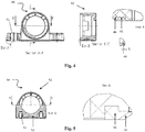
Figure 4 shows, in cross sections and associated details, an upright support element, forming part of a fourth embodiment of the invention, and -
Figure 5 shows, in a cross section and an associated detail, an upright support element with a short base, forming part of a fifth embodiment of the invention. - Referring now to the aforesaid figures, some housing elements forming part of the sealing system according to the invention are described below purely by way of example. These housing elements are used in food applications for being clamped against a machine frame and, together with an innovative rubber seal, shape the sealing system according to the present invention.
- The idea for a solution on which the present invention is based arises from the analysis of the behaviour of the rubber sealing system produced according to the suggestions of the EHEDG working group, that is to say a seal to be placed on the whole base perimeter of the housing element. In fact, it is evident from this analysis that, although the "standard" rubber profile behaves as predicted in the less "stressed" area, that is to say at a certain distance from the mounting bolts, the rubber profile is, on the contrary, excessively deformed at the position of the clamping bolts.
- The idea for a solution is therefore that of implementing a special rubber profile which is not constant along the whole perimeter of the housing element, by defining the most stressed areas for each embodiment of the invention and consequently the cross section of the rubber, and implementing a transition between two different rubber section profiles.
- In particular, a first rubber profile with a larger cross section has been designed for implementation around the areas of the bolts, that is to say the areas that are much more stressed. The second profile, with a smaller cross section, corresponding to the specifications of the aforesaid guidelines, has been retained throughout the remaining perimeter, to provide the same result, in terms of hygiene, in a less stressed area. In other words, the profile with the larger cross section (in the more stressed areas) makes it possible to produce deformations of the rubber having the same extent as the deformations produced in the less stressed areas, although the rubber profile has a smaller cross section in these areas. In other words, the principle of proportionality between the tensors of tension and the tensors of deformation of the material is used to produce virtually uniform deformations along the whole perimeter of the housing element. Theoretical considerations and experimental evidence have confirmed that the ratio between the two cross sections should preferably be between 1.25 and 1.8.
- The sealing system is preferably made from a rubber having a hardness close to a value of 70 Shore A. This value was determined by conducting experimental tests of resistance to the ingress of water and detergent, using pressure washing.
- Depending on the shape, the positioning of the transitions was modified to adapt to the specific characteristics of the shape of the housing.
- According to a first embodiment of the invention (
Fig. 1 ), the sealing system comprises a housing element which is a three-bolt flangedelement 10, provided, precisely, with threeholes 11 for bolts for clamping to the frame of a machine which is of a known type and is therefore not shown. The three-bolt flangedelement 10 comprises abody 12. The sealing system further comprises arubber seal 13 placed along the base of the three-bolt flangedelement 10. As may be seen in detail B ofFig. 1 , in the areas remote from theholes 11 for the clamping bolts, thefirst portion 14 of the rubber profile is constant and smaller than thesecond portion 15 of the rubber profile located adjacent to the holes 11 (detail A ofFig. 1 ). The ratio between the thicknesses of thesecond portion 15 and thefirst portion 14 is preferably between 1.25 and 1.8. Additionally, as it becomes more distant from the area of the holes, the rubber profile assumes atransitional cross section 16, decreasing as the distance from the area of the holes increases. - In a second embodiment of the invention (
Fig. 2 ), the sealing system comprises a housing element which is a square flangedelement 20, provided with four holes 21 for bolts for clamping to the frame of a machine which is of a known type and is therefore not shown. The square flangedelement 20 comprises abody 22. The sealing system further comprises arubber seal 23 placed along the base of the square flangedelement 20. As may be seen in detail B ofFig. 2 , in the areas remote from the holes 21 for the clamping bolts, thefirst portion 24 of the rubber profile is constant and smaller than thesecond portion 25 of the rubber profile located adjacent to the holes 21 (detail A ofFig. 2 ). The ratio between the thicknesses of thesecond portion 25 and thefirst portion 24 is preferably between 1.25 and 1.8. Additionally, as it becomes more distant from the area of the holes, the rubber profile assumes atransitional cross section 26, decreasing as the distance from the area of the holes increases. - Similarly, according to a third embodiment of the invention (
Fig. 3 ), the sealing system comprises a housing element which is an oval flangedelement 30, provided with twoholes 31 for bolts for clamping to the frame of a machine which is of a known type and is therefore not shown. The oval flangedelement 30 comprises abody 32. The sealing system further comprises arubber seal 33 placed along the base of the oval flangedelement 30. As may be seen in detail B ofFig. 3 , in the areas remote from theholes 31 for the clamping bolts, thefirst portion 34 of the rubber profile is constant and smaller than thesecond portion 35 of the rubber profile located adjacent to the holes 31 (detail A ofFig. 3 ). The ratio between the thicknesses of thesecond portion 35 and thefirst portion 34 is preferably between 1.25 and 1.8. Additionally, as it becomes more distant from the area of the holes, the rubber profile assumes atransitional cross section 36, decreasing as the distance from the area of the holes increases. - Similarly, according to a fourth embodiment of the invention (
Fig. 4 ), the sealing system comprises a housing element which is anupright support element 40, provided with twoholes 41 for bolts for clamping to the frame of a machine which is of a known type and is therefore not shown. Theupright support element 40 comprises abody 42. The sealing system further comprises a rubber seal 43 placed along the base of theupright support element 40. As may be seen in detail B ofFig. 4 , in the areas remote from theholes 41 for the clamping bolts, thefirst portion 44 of the rubber profile is constant and smaller than thesecond portion 45 of the rubber profile located adjacent to the holes 41 (detail A ofFig. 4 ). The ratio between the thicknesses of thesecond portion 45 and thefirst portion 44 is preferably between 1.25 and 1.8. Additionally, as it becomes more distant from the area of the holes, the rubber profile assumes atransitional cross section 46, decreasing as the distance from the area of the holes increases.
Similarly, according to a fourth embodiment of the invention (Fig. 5 ), the sealing system comprises a housing element which is anupright support element 50, provided with twoholes 51 for bolts for clamping to the frame of a machine which is of a known type and is therefore not shown. The short-baseupright support element 50 comprises abody 52. The sealing system further comprises arubber seal 53 placed along the base of the short-baseupright support element 50. In the areas remote from theholes 51 for the clamping bolts, the first portion 54 of the rubber profile is constant and smaller than thesecond portion 55 of the rubber profile located adjacent to the holes 51 (detail A ofFig. 5 ). The ratio between the thicknesses of thesecond portion 55 and the first portion 54 is preferably between 1.25 and 1.8. Additionally, as it becomes more distant from the area of the holes, the rubber profile assumes atransitional cross section 56, decreasing as the distance from the area of the holes increases. - The solution, presented in countless embodiments, has the evident advantage of providing a rubber profile which is deformed in a virtually constant way along the whole base perimeter of the housing element. This conforms to the provisions of the guidelines for ensuring a design that meets the requirements of hygiene, while avoiding any effect on other performance parameters such as the clamping torque during assembly.
- In addition to the embodiments of the invention as described above, it should be understood that there are numerous other variants. It should also be understood that said embodiments are described purely by way of example, and do not limit the object of the invention, or its applications, or its possible configurations. On the contrary, although the above description enables a person skilled in the art to implement the present invention at least according to an example of configuration thereof, it should be understood that numerous variations of the components described could be devised without thereby departing from the object of the invention as defined in the attached claims, whether interpreted literally and/or according to their legal equivalents.
Claims (4)
- Sealing system for food applications comprising a housing element (10, 20, 30, 40, 50) having two or more bolts and respective clamping holes (11, 21, 31, 41, 51), so as to clamp said housing element (10, 20, 30, 40, 50) to the frame of a machine and a rubber seal (13, 23, 33, 43, 53) arranged along the base perimeter of the housing element (10, 20, 30, 40, 50) and characterized in that said rubber seal (13, 23, 33, 43, 53) comprises a first portion (14, 24, 34, 44, 54) of the rubber profile located in the areas away from the holes (11, 21, 31, 41, 51) and a second portion (15, 25, 35, 45, 55) of the rubber profile adjacent to the holes (11, 21, 31, 41, 51), wherein the rubber profile of the second portion (15, 25, 35 , 45, 55) has a cross-section greater than the cross-section of the first portion (14, 24, 34, 44, 54) so as to make the deformations of the rubber profile almost uniform all along the base perimeter of the housing element, so that rubber fractures formation and consequently bacteria traps are avoided.
- System according to claim 1, characterized in that the ratio between the thickness of the second portion (15, 25, 35, 45, 55) of the rubber profile and the thickness of the first portion (14, 24, 34, 44, 54) of the rubber profile ranges between 1.25 and 1.8.
- System according to claim 1 or 2, wherein said rubber profile of the rubber seal (13, 23, 33, 43, 53) comprises a transition section (16, 26, 36, 46, 56) gradually decreasing away from the area of the holes (11, 21, 31, 41, 51) of the housing element (10, 20, 30, 40, 50).
- System according to any of the preceding claims, characterized in that the rubber seal (13, 23, 33, 43, 53) presents a hardness approximately equal to 70 Shore A.
Applications Claiming Priority (1)
| Application Number | Priority Date | Filing Date | Title |
|---|---|---|---|
| IT102018000004906A IT201800004906A1 (en) | 2018-04-27 | 2018-04-27 | SEALING SYSTEM FOR FOOD APPLICATIONS |
Publications (2)
| Publication Number | Publication Date |
|---|---|
| EP3561341A1 true EP3561341A1 (en) | 2019-10-30 |
| EP3561341B1 EP3561341B1 (en) | 2024-02-28 |
Family
ID=63244707
Family Applications (1)
| Application Number | Title | Priority Date | Filing Date |
|---|---|---|---|
| EP19169190.6A Active EP3561341B1 (en) | 2018-04-27 | 2019-04-15 | Sealing system for food applications |
Country Status (5)
| Country | Link |
|---|---|
| US (1) | US11235964B2 (en) |
| EP (1) | EP3561341B1 (en) |
| CN (2) | CN118088686A (en) |
| DK (1) | DK3561341T3 (en) |
| IT (1) | IT201800004906A1 (en) |
Families Citing this family (1)
| Publication number | Priority date | Publication date | Assignee | Title |
|---|---|---|---|---|
| SE543692C2 (en) * | 2019-10-23 | 2021-06-08 | Roxtec Ab | Compressible round seal for a lead-through maintaining the shape of a rectangular through hole when compressed |
Citations (3)
| Publication number | Priority date | Publication date | Assignee | Title |
|---|---|---|---|---|
| US4535996A (en) * | 1985-01-18 | 1985-08-20 | Felt Products Mfg. Co. | Gasket assembly for oil pans and the like and method of making same |
| DE3927340C1 (en) * | 1988-09-15 | 1990-10-31 | Dichtungstechnik G. Bruss Kg, 2071 Hoisdorf, De | IC engine rubber gasket - has semicircular section grooves and embedded rubber insert |
| CN107906282A (en) * | 2018-01-02 | 2018-04-13 | 仁兴机械(佛山)有限公司 | A kind of oil return steel pipe flange of die casting machine system |
Family Cites Families (13)
| Publication number | Priority date | Publication date | Assignee | Title |
|---|---|---|---|---|
| US4625978A (en) * | 1985-05-20 | 1986-12-02 | Parker Hannifin Corporation | Low temperature seal |
| US5121932A (en) * | 1990-11-07 | 1992-06-16 | Fel-Pro Incorporated | Gasket assembly for oil pans and the like |
| US5118121A (en) * | 1991-01-22 | 1992-06-02 | Hellman Sr Robert R | Compound gasket useful for high temperature, high pressure service |
| US5236205A (en) * | 1991-06-17 | 1993-08-17 | Fel-Pro Incorporated | Molded thermoplastic resin gasket having a compound sealing bead |
| US5536023A (en) * | 1994-10-31 | 1996-07-16 | Indian Head Industries, Inc. | One piece gasket for complex oil pan configuration |
| US6536775B1 (en) * | 2001-01-30 | 2003-03-25 | Dana Corporation | Boundary gasket with integral bolt thread seals |
| US6543787B1 (en) * | 2001-03-28 | 2003-04-08 | Dana Corporation | Boundary gasket with waffle pattern sealing beads |
| US6682081B2 (en) * | 2001-10-30 | 2004-01-27 | Inertech, Inc. | Reduced area gaskets |
| DE10247559A1 (en) * | 2002-10-11 | 2004-05-13 | Federal-Mogul Sealing Systems Bretten Gmbh & Co. Kg | sealing element |
| US7070187B2 (en) * | 2004-11-09 | 2006-07-04 | Federal-Mogul World Wide, Inc | Gasket assembly |
| US7306235B2 (en) * | 2005-07-29 | 2007-12-11 | Federal-Mogul World Wide, Inc. | Gasket assembly having isolated compression limiting device |
| JP5760411B2 (en) * | 2010-12-08 | 2015-08-12 | Nok株式会社 | gasket |
| CN107429748B (en) * | 2015-03-31 | 2019-11-08 | 斯凯孚公司 | Bearing housings specially designed for the food industry |
-
2018
- 2018-04-27 IT IT102018000004906A patent/IT201800004906A1/en unknown
-
2019
- 2019-04-04 US US16/374,812 patent/US11235964B2/en active Active
- 2019-04-15 EP EP19169190.6A patent/EP3561341B1/en active Active
- 2019-04-15 DK DK19169190.6T patent/DK3561341T3/en active
- 2019-04-22 CN CN202410357421.3A patent/CN118088686A/en active Pending
- 2019-04-22 CN CN201910323195.6A patent/CN110410499A/en active Pending
Patent Citations (3)
| Publication number | Priority date | Publication date | Assignee | Title |
|---|---|---|---|---|
| US4535996A (en) * | 1985-01-18 | 1985-08-20 | Felt Products Mfg. Co. | Gasket assembly for oil pans and the like and method of making same |
| DE3927340C1 (en) * | 1988-09-15 | 1990-10-31 | Dichtungstechnik G. Bruss Kg, 2071 Hoisdorf, De | IC engine rubber gasket - has semicircular section grooves and embedded rubber insert |
| CN107906282A (en) * | 2018-01-02 | 2018-04-13 | 仁兴机械(佛山)有限公司 | A kind of oil return steel pipe flange of die casting machine system |
Also Published As
| Publication number | Publication date |
|---|---|
| US11235964B2 (en) | 2022-02-01 |
| CN118088686A (en) | 2024-05-28 |
| DK3561341T3 (en) | 2024-05-27 |
| EP3561341B1 (en) | 2024-02-28 |
| IT201800004906A1 (en) | 2019-10-27 |
| CN110410499A (en) | 2019-11-05 |
| US20190330035A1 (en) | 2019-10-31 |
Similar Documents
| Publication | Publication Date | Title |
|---|---|---|
| US9903516B2 (en) | Press fitting and joint assembly with such a press fitting | |
| CA3024666C (en) | Fitting for producing a leak-tight connection comprising a retaining element with contact surfaces | |
| TR201807980T4 (en) | FITTINGS FOR THICK WALL PIPES AND THEIR METHOD FOR THEIR PRODUCTION | |
| CA3024047C (en) | Coupling device with grip element | |
| JPWO2020026893A1 (en) | Sealing device and gasket | |
| US11235964B2 (en) | Sealing system for food applications | |
| BR0206445A (en) | Seal, Piston Apparatus, and Seawater Desalination Plant | |
| EP2234197A1 (en) | Electrolytic corrosion prevention structure and waveguide connection structure | |
| CN103797286B (en) | Utilize the seal construction of metal gasket | |
| JP2006527339A (en) | Gate valve | |
| MA31698B1 (en) | Can be installed, dismantled and reusable | |
| JP2012502237A (en) | Slip valve | |
| CN110462270A (en) | pipe joint | |
| WO2017086178A1 (en) | Dust cover for ball joint and method for attaching dust cover for ball joint | |
| MY161303A (en) | Metal-to-metal seal assembly for a subsea well assembly | |
| JP7043029B2 (en) | How to assemble the water supply unit room and the water supply unit room | |
| US20070023985A1 (en) | Sleeve assembly for an elastomer bearing | |
| JP2005133814A (en) | Method for reinforcing junction part of fcd valve to single flange pipe | |
| JP6586308B2 (en) | tank | |
| KR20240010017A (en) | Cocks for valves and valves containing such cocks | |
| JP2016161054A (en) | Leakage prevention device at flange joint part | |
| KR20110055103A (en) | Foreign metal seat butterfly valve | |
| GB2316720A (en) | Gasket | |
| JP2002030892A (en) | segment | |
| WO2018203730A3 (en) | Sealing members for gasket, and gasket comprising same |
Legal Events
| Date | Code | Title | Description |
|---|---|---|---|
| PUAI | Public reference made under article 153(3) epc to a published international application that has entered the european phase |
Free format text: ORIGINAL CODE: 0009012 |
|
| STAA | Information on the status of an ep patent application or granted ep patent |
Free format text: STATUS: THE APPLICATION HAS BEEN PUBLISHED |
|
| AK | Designated contracting states |
Kind code of ref document: A1 Designated state(s): AL AT BE BG CH CY CZ DE DK EE ES FI FR GB GR HR HU IE IS IT LI LT LU LV MC MK MT NL NO PL PT RO RS SE SI SK SM TR |
|
| AX | Request for extension of the european patent |
Extension state: BA ME |
|
| STAA | Information on the status of an ep patent application or granted ep patent |
Free format text: STATUS: REQUEST FOR EXAMINATION WAS MADE |
|
| 17P | Request for examination filed |
Effective date: 20200430 |
|
| RBV | Designated contracting states (corrected) |
Designated state(s): AL AT BE BG CH CY CZ DE DK EE ES FI FR GB GR HR HU IE IS IT LI LT LU LV MC MK MT NL NO PL PT RO RS SE SI SK SM TR |
|
| RAP3 | Party data changed (applicant data changed or rights of an application transferred) |
Owner name: AKTIEBOLAGET SKF |
|
| STAA | Information on the status of an ep patent application or granted ep patent |
Free format text: STATUS: EXAMINATION IS IN PROGRESS |
|
| 17Q | First examination report despatched |
Effective date: 20220215 |
|
| GRAP | Despatch of communication of intention to grant a patent |
Free format text: ORIGINAL CODE: EPIDOSNIGR1 |
|
| STAA | Information on the status of an ep patent application or granted ep patent |
Free format text: STATUS: GRANT OF PATENT IS INTENDED |
|
| INTG | Intention to grant announced |
Effective date: 20230926 |
|
| GRAS | Grant fee paid |
Free format text: ORIGINAL CODE: EPIDOSNIGR3 |
|
| P01 | Opt-out of the competence of the unified patent court (upc) registered |
Effective date: 20231218 |
|
| GRAA | (expected) grant |
Free format text: ORIGINAL CODE: 0009210 |
|
| STAA | Information on the status of an ep patent application or granted ep patent |
Free format text: STATUS: THE PATENT HAS BEEN GRANTED |
|
| AK | Designated contracting states |
Kind code of ref document: B1 Designated state(s): AL AT BE BG CH CY CZ DE DK EE ES FI FR GB GR HR HU IE IS IT LI LT LU LV MC MK MT NL NO PL PT RO RS SE SI SK SM TR |
|
| REG | Reference to a national code |
Ref country code: GB Ref legal event code: FG4D |
|
| REG | Reference to a national code |
Ref country code: CH Ref legal event code: EP |
|
| REG | Reference to a national code |
Ref country code: DE Ref legal event code: R096 Ref document number: 602019047182 Country of ref document: DE |
|
| REG | Reference to a national code |
Ref country code: IE Ref legal event code: FG4D |
|
| REG | Reference to a national code |
Ref country code: DK Ref legal event code: T3 Effective date: 20240522 |
|
| REG | Reference to a national code |
Ref country code: LT Ref legal event code: MG9D |
|
| REG | Reference to a national code |
Ref country code: NL Ref legal event code: FP |
|
| PG25 | Lapsed in a contracting state [announced via postgrant information from national office to epo] |
Ref country code: IS Free format text: LAPSE BECAUSE OF FAILURE TO SUBMIT A TRANSLATION OF THE DESCRIPTION OR TO PAY THE FEE WITHIN THE PRESCRIBED TIME-LIMIT Effective date: 20240628 |
|
| PG25 | Lapsed in a contracting state [announced via postgrant information from national office to epo] |
Ref country code: LT Free format text: LAPSE BECAUSE OF FAILURE TO SUBMIT A TRANSLATION OF THE DESCRIPTION OR TO PAY THE FEE WITHIN THE PRESCRIBED TIME-LIMIT Effective date: 20240228 |
|
| PG25 | Lapsed in a contracting state [announced via postgrant information from national office to epo] |
Ref country code: GR Free format text: LAPSE BECAUSE OF FAILURE TO SUBMIT A TRANSLATION OF THE DESCRIPTION OR TO PAY THE FEE WITHIN THE PRESCRIBED TIME-LIMIT Effective date: 20240529 |
|
| PG25 | Lapsed in a contracting state [announced via postgrant information from national office to epo] |
Ref country code: RS Free format text: LAPSE BECAUSE OF FAILURE TO SUBMIT A TRANSLATION OF THE DESCRIPTION OR TO PAY THE FEE WITHIN THE PRESCRIBED TIME-LIMIT Effective date: 20240528 Ref country code: HR Free format text: LAPSE BECAUSE OF FAILURE TO SUBMIT A TRANSLATION OF THE DESCRIPTION OR TO PAY THE FEE WITHIN THE PRESCRIBED TIME-LIMIT Effective date: 20240228 |
|
| PG25 | Lapsed in a contracting state [announced via postgrant information from national office to epo] |
Ref country code: ES Free format text: LAPSE BECAUSE OF FAILURE TO SUBMIT A TRANSLATION OF THE DESCRIPTION OR TO PAY THE FEE WITHIN THE PRESCRIBED TIME-LIMIT Effective date: 20240228 |
|
| PG25 | Lapsed in a contracting state [announced via postgrant information from national office to epo] |
Ref country code: RS Free format text: LAPSE BECAUSE OF FAILURE TO SUBMIT A TRANSLATION OF THE DESCRIPTION OR TO PAY THE FEE WITHIN THE PRESCRIBED TIME-LIMIT Effective date: 20240528 Ref country code: NO Free format text: LAPSE BECAUSE OF FAILURE TO SUBMIT A TRANSLATION OF THE DESCRIPTION OR TO PAY THE FEE WITHIN THE PRESCRIBED TIME-LIMIT Effective date: 20240528 Ref country code: LT Free format text: LAPSE BECAUSE OF FAILURE TO SUBMIT A TRANSLATION OF THE DESCRIPTION OR TO PAY THE FEE WITHIN THE PRESCRIBED TIME-LIMIT Effective date: 20240228 Ref country code: IS Free format text: LAPSE BECAUSE OF FAILURE TO SUBMIT A TRANSLATION OF THE DESCRIPTION OR TO PAY THE FEE WITHIN THE PRESCRIBED TIME-LIMIT Effective date: 20240628 Ref country code: HR Free format text: LAPSE BECAUSE OF FAILURE TO SUBMIT A TRANSLATION OF THE DESCRIPTION OR TO PAY THE FEE WITHIN THE PRESCRIBED TIME-LIMIT Effective date: 20240228 Ref country code: GR Free format text: LAPSE BECAUSE OF FAILURE TO SUBMIT A TRANSLATION OF THE DESCRIPTION OR TO PAY THE FEE WITHIN THE PRESCRIBED TIME-LIMIT Effective date: 20240529 Ref country code: FI Free format text: LAPSE BECAUSE OF FAILURE TO SUBMIT A TRANSLATION OF THE DESCRIPTION OR TO PAY THE FEE WITHIN THE PRESCRIBED TIME-LIMIT Effective date: 20240228 Ref country code: ES Free format text: LAPSE BECAUSE OF FAILURE TO SUBMIT A TRANSLATION OF THE DESCRIPTION OR TO PAY THE FEE WITHIN THE PRESCRIBED TIME-LIMIT Effective date: 20240228 Ref country code: BG Free format text: LAPSE BECAUSE OF FAILURE TO SUBMIT A TRANSLATION OF THE DESCRIPTION OR TO PAY THE FEE WITHIN THE PRESCRIBED TIME-LIMIT Effective date: 20240228 |
|
| PG25 | Lapsed in a contracting state [announced via postgrant information from national office to epo] |
Ref country code: PL Free format text: LAPSE BECAUSE OF FAILURE TO SUBMIT A TRANSLATION OF THE DESCRIPTION OR TO PAY THE FEE WITHIN THE PRESCRIBED TIME-LIMIT Effective date: 20240228 Ref country code: PT Free format text: LAPSE BECAUSE OF FAILURE TO SUBMIT A TRANSLATION OF THE DESCRIPTION OR TO PAY THE FEE WITHIN THE PRESCRIBED TIME-LIMIT Effective date: 20240628 |
|
| REG | Reference to a national code |
Ref country code: AT Ref legal event code: MK05 Ref document number: 1661530 Country of ref document: AT Kind code of ref document: T Effective date: 20240228 |
|
| PG25 | Lapsed in a contracting state [announced via postgrant information from national office to epo] |
Ref country code: SE Free format text: LAPSE BECAUSE OF FAILURE TO SUBMIT A TRANSLATION OF THE DESCRIPTION OR TO PAY THE FEE WITHIN THE PRESCRIBED TIME-LIMIT Effective date: 20240228 Ref country code: PT Free format text: LAPSE BECAUSE OF FAILURE TO SUBMIT A TRANSLATION OF THE DESCRIPTION OR TO PAY THE FEE WITHIN THE PRESCRIBED TIME-LIMIT Effective date: 20240628 Ref country code: PL Free format text: LAPSE BECAUSE OF FAILURE TO SUBMIT A TRANSLATION OF THE DESCRIPTION OR TO PAY THE FEE WITHIN THE PRESCRIBED TIME-LIMIT Effective date: 20240228 Ref country code: LV Free format text: LAPSE BECAUSE OF FAILURE TO SUBMIT A TRANSLATION OF THE DESCRIPTION OR TO PAY THE FEE WITHIN THE PRESCRIBED TIME-LIMIT Effective date: 20240228 |
|
| PG25 | Lapsed in a contracting state [announced via postgrant information from national office to epo] |
Ref country code: SM Free format text: LAPSE BECAUSE OF FAILURE TO SUBMIT A TRANSLATION OF THE DESCRIPTION OR TO PAY THE FEE WITHIN THE PRESCRIBED TIME-LIMIT Effective date: 20240228 |
|
| PG25 | Lapsed in a contracting state [announced via postgrant information from national office to epo] |
Ref country code: EE Free format text: LAPSE BECAUSE OF FAILURE TO SUBMIT A TRANSLATION OF THE DESCRIPTION OR TO PAY THE FEE WITHIN THE PRESCRIBED TIME-LIMIT Effective date: 20240228 Ref country code: CZ Free format text: LAPSE BECAUSE OF FAILURE TO SUBMIT A TRANSLATION OF THE DESCRIPTION OR TO PAY THE FEE WITHIN THE PRESCRIBED TIME-LIMIT Effective date: 20240228 |
|
| PG25 | Lapsed in a contracting state [announced via postgrant information from national office to epo] |
Ref country code: AT Free format text: LAPSE BECAUSE OF FAILURE TO SUBMIT A TRANSLATION OF THE DESCRIPTION OR TO PAY THE FEE WITHIN THE PRESCRIBED TIME-LIMIT Effective date: 20240228 |
|
| PG25 | Lapsed in a contracting state [announced via postgrant information from national office to epo] |
Ref country code: SK Free format text: LAPSE BECAUSE OF FAILURE TO SUBMIT A TRANSLATION OF THE DESCRIPTION OR TO PAY THE FEE WITHIN THE PRESCRIBED TIME-LIMIT Effective date: 20240228 |
|
| PG25 | Lapsed in a contracting state [announced via postgrant information from national office to epo] |
Ref country code: SM Free format text: LAPSE BECAUSE OF FAILURE TO SUBMIT A TRANSLATION OF THE DESCRIPTION OR TO PAY THE FEE WITHIN THE PRESCRIBED TIME-LIMIT Effective date: 20240228 Ref country code: SK Free format text: LAPSE BECAUSE OF FAILURE TO SUBMIT A TRANSLATION OF THE DESCRIPTION OR TO PAY THE FEE WITHIN THE PRESCRIBED TIME-LIMIT Effective date: 20240228 Ref country code: RO Free format text: LAPSE BECAUSE OF FAILURE TO SUBMIT A TRANSLATION OF THE DESCRIPTION OR TO PAY THE FEE WITHIN THE PRESCRIBED TIME-LIMIT Effective date: 20240228 Ref country code: EE Free format text: LAPSE BECAUSE OF FAILURE TO SUBMIT A TRANSLATION OF THE DESCRIPTION OR TO PAY THE FEE WITHIN THE PRESCRIBED TIME-LIMIT Effective date: 20240228 Ref country code: CZ Free format text: LAPSE BECAUSE OF FAILURE TO SUBMIT A TRANSLATION OF THE DESCRIPTION OR TO PAY THE FEE WITHIN THE PRESCRIBED TIME-LIMIT Effective date: 20240228 Ref country code: AT Free format text: LAPSE BECAUSE OF FAILURE TO SUBMIT A TRANSLATION OF THE DESCRIPTION OR TO PAY THE FEE WITHIN THE PRESCRIBED TIME-LIMIT Effective date: 20240228 |
|
| PG25 | Lapsed in a contracting state [announced via postgrant information from national office to epo] |
Ref country code: MC Free format text: LAPSE BECAUSE OF FAILURE TO SUBMIT A TRANSLATION OF THE DESCRIPTION OR TO PAY THE FEE WITHIN THE PRESCRIBED TIME-LIMIT Effective date: 20240228 |
|
| PG25 | Lapsed in a contracting state [announced via postgrant information from national office to epo] |
Ref country code: MC Free format text: LAPSE BECAUSE OF FAILURE TO SUBMIT A TRANSLATION OF THE DESCRIPTION OR TO PAY THE FEE WITHIN THE PRESCRIBED TIME-LIMIT Effective date: 20240228 |
|
| REG | Reference to a national code |
Ref country code: DE Ref legal event code: R097 Ref document number: 602019047182 Country of ref document: DE Ref country code: CH Ref legal event code: PL |
|
| PG25 | Lapsed in a contracting state [announced via postgrant information from national office to epo] |
Ref country code: LU Free format text: LAPSE BECAUSE OF NON-PAYMENT OF DUE FEES Effective date: 20240415 |
|
| PG25 | Lapsed in a contracting state [announced via postgrant information from national office to epo] |
Ref country code: LU Free format text: LAPSE BECAUSE OF NON-PAYMENT OF DUE FEES Effective date: 20240415 |
|
| PLBE | No opposition filed within time limit |
Free format text: ORIGINAL CODE: 0009261 |
|
| STAA | Information on the status of an ep patent application or granted ep patent |
Free format text: STATUS: NO OPPOSITION FILED WITHIN TIME LIMIT |
|
| PG25 | Lapsed in a contracting state [announced via postgrant information from national office to epo] |
Ref country code: CH Free format text: LAPSE BECAUSE OF NON-PAYMENT OF DUE FEES Effective date: 20240430 |
|
| 26N | No opposition filed |
Effective date: 20241129 |
|
| PG25 | Lapsed in a contracting state [announced via postgrant information from national office to epo] |
Ref country code: IE Free format text: LAPSE BECAUSE OF NON-PAYMENT OF DUE FEES Effective date: 20240415 |
|
| PG25 | Lapsed in a contracting state [announced via postgrant information from national office to epo] |
Ref country code: SI Free format text: LAPSE BECAUSE OF FAILURE TO SUBMIT A TRANSLATION OF THE DESCRIPTION OR TO PAY THE FEE WITHIN THE PRESCRIBED TIME-LIMIT Effective date: 20240228 |
|
| PG25 | Lapsed in a contracting state [announced via postgrant information from national office to epo] |
Ref country code: CY Free format text: LAPSE BECAUSE OF FAILURE TO SUBMIT A TRANSLATION OF THE DESCRIPTION OR TO PAY THE FEE WITHIN THE PRESCRIBED TIME-LIMIT; INVALID AB INITIO Effective date: 20190415 |
|
| PG25 | Lapsed in a contracting state [announced via postgrant information from national office to epo] |
Ref country code: HU Free format text: LAPSE BECAUSE OF FAILURE TO SUBMIT A TRANSLATION OF THE DESCRIPTION OR TO PAY THE FEE WITHIN THE PRESCRIBED TIME-LIMIT; INVALID AB INITIO Effective date: 20190415 |
|
| PGFP | Annual fee paid to national office [announced via postgrant information from national office to epo] |
Ref country code: NL Payment date: 20260423 Year of fee payment: 8 |
|
| PG25 | Lapsed in a contracting state [announced via postgrant information from national office to epo] |
Ref country code: TR Free format text: LAPSE BECAUSE OF FAILURE TO SUBMIT A TRANSLATION OF THE DESCRIPTION OR TO PAY THE FEE WITHIN THE PRESCRIBED TIME-LIMIT Effective date: 20240228 |
|
| PGFP | Annual fee paid to national office [announced via postgrant information from national office to epo] |
Ref country code: GB Payment date: 20260421 Year of fee payment: 8 Ref country code: DK Payment date: 20260423 Year of fee payment: 8 |
|
| PGFP | Annual fee paid to national office [announced via postgrant information from national office to epo] |
Ref country code: IT Payment date: 20260422 Year of fee payment: 8 |
|
| PGFP | Annual fee paid to national office [announced via postgrant information from national office to epo] |
Ref country code: DE Payment date: 20260421 Year of fee payment: 8 |
|
| PGFP | Annual fee paid to national office [announced via postgrant information from national office to epo] |
Ref country code: BE Payment date: 20260421 Year of fee payment: 8 |
|
| PGFP | Annual fee paid to national office [announced via postgrant information from national office to epo] |
Ref country code: FR Payment date: 20260423 Year of fee payment: 8 |