EP3561331A1 - Actuator with rotating electromagnetic clutch utilizing inductive coupling - Google Patents
Actuator with rotating electromagnetic clutch utilizing inductive coupling Download PDFInfo
- Publication number
- EP3561331A1 EP3561331A1 EP19171315.5A EP19171315A EP3561331A1 EP 3561331 A1 EP3561331 A1 EP 3561331A1 EP 19171315 A EP19171315 A EP 19171315A EP 3561331 A1 EP3561331 A1 EP 3561331A1
- Authority
- EP
- European Patent Office
- Prior art keywords
- winding
- clutch
- drive shaft
- operable
- rotatable portion
- Prior art date
- Legal status (The legal status is an assumption and is not a legal conclusion. Google has not performed a legal analysis and makes no representation as to the accuracy of the status listed.)
- Granted
Links
Images


Classifications
-
- F—MECHANICAL ENGINEERING; LIGHTING; HEATING; WEAPONS; BLASTING
- F16—ENGINEERING ELEMENTS AND UNITS; GENERAL MEASURES FOR PRODUCING AND MAINTAINING EFFECTIVE FUNCTIONING OF MACHINES OR INSTALLATIONS; THERMAL INSULATION IN GENERAL
- F16D—COUPLINGS FOR TRANSMITTING ROTATION; CLUTCHES; BRAKES
- F16D27/00—Magnetically- or electrically- actuated clutches; Control or electric circuits therefor
- F16D27/02—Magnetically- or electrically- actuated clutches; Control or electric circuits therefor with electromagnets incorporated in the clutch, i.e. with collecting rings
- F16D27/04—Magnetically- or electrically- actuated clutches; Control or electric circuits therefor with electromagnets incorporated in the clutch, i.e. with collecting rings with axially-movable friction surfaces
- F16D27/06—Magnetically- or electrically- actuated clutches; Control or electric circuits therefor with electromagnets incorporated in the clutch, i.e. with collecting rings with axially-movable friction surfaces with friction surfaces arranged within the flux
-
- F—MECHANICAL ENGINEERING; LIGHTING; HEATING; WEAPONS; BLASTING
- F16—ENGINEERING ELEMENTS AND UNITS; GENERAL MEASURES FOR PRODUCING AND MAINTAINING EFFECTIVE FUNCTIONING OF MACHINES OR INSTALLATIONS; THERMAL INSULATION IN GENERAL
- F16D—COUPLINGS FOR TRANSMITTING ROTATION; CLUTCHES; BRAKES
- F16D27/00—Magnetically- or electrically- actuated clutches; Control or electric circuits therefor
- F16D27/02—Magnetically- or electrically- actuated clutches; Control or electric circuits therefor with electromagnets incorporated in the clutch, i.e. with collecting rings
- F16D27/09—Magnetically- or electrically- actuated clutches; Control or electric circuits therefor with electromagnets incorporated in the clutch, i.e. with collecting rings and with interengaging jaws or gear-teeth
-
- H—ELECTRICITY
- H02—GENERATION; CONVERSION OR DISTRIBUTION OF ELECTRIC POWER
- H02K—DYNAMO-ELECTRIC MACHINES
- H02K7/00—Arrangements for handling mechanical energy structurally associated with dynamo-electric machines, e.g. structural association with mechanical driving motors or auxiliary dynamo-electric machines
- H02K7/10—Structural association with clutches, brakes, gears, pulleys or mechanical starters
- H02K7/11—Structural association with clutches, brakes, gears, pulleys or mechanical starters with dynamo-electric clutches
-
- H—ELECTRICITY
- H02—GENERATION; CONVERSION OR DISTRIBUTION OF ELECTRIC POWER
- H02P—CONTROL OR REGULATION OF ELECTRIC MOTORS, ELECTRIC GENERATORS OR DYNAMO-ELECTRIC CONVERTERS; CONTROLLING TRANSFORMERS, REACTORS OR CHOKE COILS
- H02P15/00—Arrangements for controlling dynamo-electric brakes or clutches
-
- F—MECHANICAL ENGINEERING; LIGHTING; HEATING; WEAPONS; BLASTING
- F16—ENGINEERING ELEMENTS AND UNITS; GENERAL MEASURES FOR PRODUCING AND MAINTAINING EFFECTIVE FUNCTIONING OF MACHINES OR INSTALLATIONS; THERMAL INSULATION IN GENERAL
- F16D—COUPLINGS FOR TRANSMITTING ROTATION; CLUTCHES; BRAKES
- F16D27/00—Magnetically- or electrically- actuated clutches; Control or electric circuits therefor
- F16D2027/001—Means for electric connection of the coils of the electromagnetic clutches
-
- F—MECHANICAL ENGINEERING; LIGHTING; HEATING; WEAPONS; BLASTING
- F16—ENGINEERING ELEMENTS AND UNITS; GENERAL MEASURES FOR PRODUCING AND MAINTAINING EFFECTIVE FUNCTIONING OF MACHINES OR INSTALLATIONS; THERMAL INSULATION IN GENERAL
- F16D—COUPLINGS FOR TRANSMITTING ROTATION; CLUTCHES; BRAKES
- F16D27/00—Magnetically- or electrically- actuated clutches; Control or electric circuits therefor
Definitions
- This application relates to clutches, and more particularly to an actuator that includes a rotatable electromagnetic clutch utilizing an inductive coupling.
- Clutches are used to selectively couple a drive shaft to a load shaft to drive a load.
- a common application for a clutch is selectively coupling a vehicle engine to a transmission to transmit driving torque to wheels of the vehicle, for example.
- Electromagnetic clutches utilize an electromagnetic field to cause a clutch plate to engage or disengage from an armature coupled to the load shaft.
- direct current DC
- DC is typically provided to the electromagnetic coil through brushes. Brushes are subject to wear and are therefore considered unreliable for certain applications.
- An example electromagnetic actuator includes a drive shaft, a motor operable to rotate the drive shaft, and a load shaft coupled to an armature body.
- a clutch is operable to control whether the drive shaft engages the load shaft.
- a rotatable portion of the clutch corotates with the drive shaft and includes a field winding and a clutch body.
- a stationary portion of the clutch includes an exciter winding that is inductively coupled to the rotatable portion and is operable to energize the field winding.
- the field winding is operable, when energized, to provide a magnetic field that causes engagement or disengagement between the clutch body and an armature body
- An example method of operating an electromagnetic actuator includes operating a motor to rotate a drive shaft.
- a field winding in a rotatable portion of an electromagnetic clutch assembly is energized through an inductive coupling between the rotatable portion and an exciter winding in a stationary portion of the electromagnetic clutch assembly.
- the rotatable portion corotates with the drive shaft.
- a magnetic field generated from the field winding urges engagement or disengagement between a clutch body of the rotatable portion and an armature body of the stationary portion that corotates with a load shaft.
- An example electromagnetic actuator includes a drive shaft, a motor operable to rotate the drive shaft, a load shaft coupled to an armature body, and a clutch operable to control whether the drive shaft engages the load shaft.
- the clutch includes a rotatable portion having an inductive winding and a field winding.
- the clutch also includes a stationary portion having an exciter winding configured such that during rotation of the rotatable portion when electrical power is supplied to the exciter winding, electrical power is induced in the inductive winding and transferred to the field winding to generate a magnetic field to urge engagement or disengagement between the rotatable portion and the stationary portion.
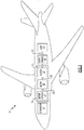
- Figure 1 is a schematic view of an aircraft 10 that utilizes an electromagnetic actuator 16 that includes an electromagnetic clutch assembly 18.
- the actuator 16 also includes a motor 20 that drives rotation of a drive shaft 22.
- the electromagnetic clutch assembly 18 controls whether the drive shaft 22 is coupled to a load shaft 24 that drives a load 25.
- a motor sensor 26 is operable to determine an angular position of the motor 20 or drive shaft 22, and an output sensor 28 is operable to determine an angular position of the load shaft 24.
- the electromagnetic actuator 16 could be used for a variety of aircraft 10 features, such as braking, primary flight controls (e.g., aileron control, rudder control, etc.), landing gear operation, etc.
- braking e.g., aileron control, rudder control, etc.
- primary flight controls e.g., aileron control, rudder control, etc.
- landing gear operation etc.
- FIG 2 is a schematic view of an example actuator 16 that can be used in the aircraft 10 of Figure 1 .
- the actuator 16 includes the electromagnetic clutch assembly 18, motor 20, motor sensor 16, and output sensor 28 shown in Figure 1 .
- the motor sensor 26 and output sensor 28 are each resolvers. However, is understood that other types of sensors could be used.
- the motor 20 includes a plurality of windings 21A-C in a stator 30. Each winding 21A-C corresponds to a phase of current.
- the stator windings 21A-C drive rotation of rotor 32 and drive shaft 22.
- a controller 64 is operable to provide current to the windings 21 for operation of the motor 20 based on a rotational position of the drive shaft 22 determined from motor sensor 26.
- the controller 64 is configured to energize primary winding 27A of motor sensor 26, and read sine winding 27B and cosine winding 27C of motor sensor 26.
- the controller 64 is similarly configured to energize primary winding 29A of output sensor 28 and read sine winding 29B and cosine winding 29C of output sensor 28.
- the controller 64 energizes the windings 21A-C, 27A, and 29A utilizing alternating current (AC).
- the AC is provided by generator 14 in one example.
- the AC from the generator 14 is rectified to DC, and the controller 64 utilizes an inverter (not shown in Figure 2 ) to convert that DC to AC for energizing the windings 21A-C, 27A, and 29A.
- inverter not shown in Figure 2
- windings 21A-C, 27A-C, and 29A-C are all schematically shown as being connected to controller 64 in Figure 2 , it is understood that one or more of the windings could be connected to a component controlled by the controller 64 (such as an inverter).
- An optional gear set 38 interconnects a first portion 22A and a second potion 22B of the drive shaft.
- the first and second portions 22A-B are coaxial and both rotate about a central longitudinal axis A.
- FIG 3 is a schematic view of the example electromagnetic clutch assembly 18 of Figure 2 in greater detail.
- the electromagnetic clutch assembly 18 includes a rotatable portion and a stationary portion.
- the rotatable portion includes at least one inductive winding 33, a rectifier 34, a clutch body 35, and a field winding 36 that is at least partially disposed within the clutch body 35.
- the rotatable portion is rotatable about the central longitudinal axis A.
- the stationary portion includes at least one exciter winding 40 and the clutch housing 42.
- the at least one exciter winding 40 is inductively coupled to the rotatable portion, and is operable to energize the field winding 36.
- the field winding 36 when energized, is operable to provide a magnetic field that causes engagement or disengagement between the clutch body 34 and an armature body 50.
- the at least one exciter winding 40 which is stationary, and the at least one inductive winding 33, which is rotatable, are inductively coupled or "field-coupled.”
- two windings being “inductively coupled” means that that current in one of the windings induces a voltage in the other of the windings through electromagnetic induction.
- the at least one exciter winding 40 receives current from the power source 68 and induces current in the at least one inductive winding 33.
- This field-coupled arrangement avoids the need for brushes, and avoids the reliability issues typically associated with using brushes.
- the armature body 50 is coupled to a splined hub 52.
- the armature body 50 and splined hub 52 corotate with the load shaft 24.
- the armature body 50 includes an armature plate 54 and at least one splined armature member 56 that mates with the splined hub 52.
- the armature body 50 is movable along the central longitudinal axis A with respect to the splined hub 52 to engage or disengage from the clutch body 35.
- At least one spring 58 provides a bias force to the armature plate 54.
- the spring(s) 58 are tension springs that provides a bias force that biases the armature plate 54 away from the clutch body 35 (a "power off - disengaged" configuration).
- the magnetic field from the at least one field winding 36 resists the bias force and causes the armature body 50 to engage the clutch body 35.
- the spring(s) 58 are compression springs that provides a bias force that biases the armature body 50 towards the clutch body 35 (a "power off - engaged" configuration), and the magnetic field from the at least one field winding 36 causes the armature body 50 to disengage from the clutch body 35.
- the at least one spring 58 is mounted to the splined hub 52 and the armature plate 54.
- the at least one spring 58 could be mounted on an opposite side of the armature plate 54, and could connect the armature plate 54 to the clutch body 35.
- the clutch body 35 comprises a plurality of teeth 60 on a face 61 of the clutch body 35 that are operable to engage teeth 62 of the armature body 50.
- teeth 60 instead of teeth 60 at least one of the face 61 of the clutch body 35 and the armature plate 54 have a high friction surface for engaging the face 61 with the armature plate 54.
- a "high friction" surface is one having a higher coefficient of friction than the base substrate on which the high friction surface is situated (e.g., face 61 having a higher coefficient of friction than the portion of the clutch body 35 behind the face 61).
- At least one proximity sensor 63 is configured to measure axial displacement of the armature body 50 along the longitudinal axis A.
- the controller 64 is operable to verify whether the clutch body 35 and armature body 50 are engaged or disengaged based on feedback from the at least one proximity sensor 63 and/or the output sensor 28.
- the controller 64 is operable to utilize pulse width modulation (PWM) to power the at least one exciter winding 40.
- PWM pulse width modulation
- the controller 64 operates an inverter 66 to convert DC from a power source 68 to AC for energizing the at least one exciter winding 40 through leads 41 that extend outside of the clutch housing 42.
- the controller 64 operates the inverter 66 based on feedback from the at least one proximity sensor 63 (e.g., adjusting strength of the magnetic field from field winding(s) 36 based on an axial position of the armature body 50).
- the sensor 63 also enables the controller 64 to perform its own testing of the electromagnetic clutch assembly 18.
- the power source 68 could be powered by the generator 14 in Figure 1 , for example.
- the same inverter 66 is used by the controller 64 to convert DC to AC for energizing the windings 21A-C, 27A, and 29A.
- Bearings 69A and 69B enable rotation of the drive shaft 22 relative to the clutch housing 42, and bearings 69C and 69D similarly enable rotation of the load shaft 24 relative to the clutch housing 42.
- the exciter winding 40 induces alternating current (AC) in the at least one inductive winding 33.
- the rectifier 34 rectifies the AC and provides DC to the at least one field winding 36.
- Other quantities of windings could be used, however, such as one or more than two exciter windings 40, and one or more than two inductive windings 33, and more than one field winding 36.
- Figure 4 is a schematic view of an interface between the splined armature member 56 and the splined hub 52.
- the splined hub 52 includes a plurality of splined teeth 53 disposed along an outer diameter of the splined hub 52
- the splined armature member 56 includes a plurality of splined teeth 57 disposed along an inner diameter of the splined armature member 56.
- the splined teeth 53 of the splined hub 52 engage the splined teeth 57 of the splined armature member 56.
- Both of the splined hub 52 and splined armature member 56 rotate about the central longitudinal axis A when the clutch body 35 and armature body 50 are engaged.
- Figure 5 is a schematic view of an example implementation of the rectifier 34.
- the at least one inductive winding 33 includes a plurality of inductive windings 33A-C, each corresponding to a phase of electrical current
- the rectifier 34 includes a respective diode 70A-C that rectifies current from its respective inductive winding 33A-C.
- a return diode 72 is also included.
- Figure 6 is a flowchart 100 representative of an example method of operating an electromagnetic actuator 16.
- the method includes operating a motor to rotate a drive shaft 22 (block 102).
- a field winding 36 in a rotatable portion of an electromagnetic clutch assembly 18 is energized through an inductive coupling between the rotatable portion and an exciter winding 40 in a stationary portion of the electromagnetic clutch assembly 18 (block 104).
- a magnetic field is generated from the field winding 36 that urges engagement or disengagement between clutch body 35 of the rotatable portion and armature body 50 of the stationary portion which corotates with the load shaft 24 (block 106).
- energizing the field winding 36 includes inducing current in the inductive winding 33 of the rotatable portion, rectifying the induced current using rectifier 34, and providing the rectified current to the field winding 36.
- the rectifier 34 and inductive winding 33 are omitted, and the exciter winding 40 induces current in the field winding 36.
- Figure 3 illustrates the clutch body 35 as being axially stationary while the armature body 50 is movable along the central longitudinal axis A
- the clutch body 35 is axially movable along the central longitudinal axis A in addition to or as an alternative to the armature body 50 being axially movable.
- the electromagnetic clutch assembly 18 discussed herein avoids the brushed configuration of prior art electromagnetic clutches, and therefore improves reliability.
- the electromagnetic clutch assembly 18 also expands potential uses for electronic actuators to certain aerospace applications, for which the reliability of traditional electromagnetic clutches that use contact brushes would not be sufficient.
Landscapes
- Engineering & Computer Science (AREA)
- General Engineering & Computer Science (AREA)
- Physics & Mathematics (AREA)
- Electromagnetism (AREA)
- Mechanical Engineering (AREA)
- Power Engineering (AREA)
- Hydraulic Clutches, Magnetic Clutches, Fluid Clutches, And Fluid Joints (AREA)
- Automation & Control Theory (AREA)
- Aviation & Aerospace Engineering (AREA)
Abstract
Description
- This application relates to clutches, and more particularly to an actuator that includes a rotatable electromagnetic clutch utilizing an inductive coupling.
- Clutches are used to selectively couple a drive shaft to a load shaft to drive a load. A common application for a clutch is selectively coupling a vehicle engine to a transmission to transmit driving torque to wheels of the vehicle, for example.
- Electromagnetic clutches utilize an electromagnetic field to cause a clutch plate to engage or disengage from an armature coupled to the load shaft. In a typical configuration, direct current (DC) is provided to an electromagnetic coil, which creates a magnetic field causing the armature to engage a clutch plate. DC is typically provided to the electromagnetic coil through brushes. Brushes are subject to wear and are therefore considered unreliable for certain applications.
- An example electromagnetic actuator includes a drive shaft, a motor operable to rotate the drive shaft, and a load shaft coupled to an armature body. A clutch is operable to control whether the drive shaft engages the load shaft. A rotatable portion of the clutch corotates with the drive shaft and includes a field winding and a clutch body. A stationary portion of the clutch includes an exciter winding that is inductively coupled to the rotatable portion and is operable to energize the field winding. The field winding is operable, when energized, to provide a magnetic field that causes engagement or disengagement between the clutch body and an armature body
- An example method of operating an electromagnetic actuator includes operating a motor to rotate a drive shaft. A field winding in a rotatable portion of an electromagnetic clutch assembly is energized through an inductive coupling between the rotatable portion and an exciter winding in a stationary portion of the electromagnetic clutch assembly. The rotatable portion corotates with the drive shaft. A magnetic field generated from the field winding urges engagement or disengagement between a clutch body of the rotatable portion and an armature body of the stationary portion that corotates with a load shaft.
- An example electromagnetic actuator includes a drive shaft, a motor operable to rotate the drive shaft, a load shaft coupled to an armature body, and a clutch operable to control whether the drive shaft engages the load shaft. The clutch includes a rotatable portion having an inductive winding and a field winding. The clutch also includes a stationary portion having an exciter winding configured such that during rotation of the rotatable portion when electrical power is supplied to the exciter winding, electrical power is induced in the inductive winding and transferred to the field winding to generate a magnetic field to urge engagement or disengagement between the rotatable portion and the stationary portion.
- The embodiments, examples, and alternatives of the preceding paragraphs, the claims, or the following description and drawings, including any of their various aspects or respective individual features, may be taken independently or in any combination. Features described in connection with one embodiment are applicable to all embodiments, unless such features are incompatible.
-
-
Figure 1 is a schematic view of an aircraft that utilizes an actuator with an electromagnetic clutch. -
Figure 2 is a schematic view of an example actuator that can be used in the aircraft ofFigure 1 . -
Figure 3 is an enlarged schematic view of an electromagnetic clutch assembly ofFigure 2 . -
Figure 4 is a schematic view of an interface between an armature body and a splined hub in the electromagnetic clutch assembly ofFigure 3 . -
Figure 5 is a schematic view of an example rectifier for the electromagnetic clutch assembly ofFigure 3 . -
Figure 6 is a flowchart representative of an example method of operating an electromagnetic actuator. -
Figure 1 is a schematic view of anaircraft 10 that utilizes anelectromagnetic actuator 16 that includes anelectromagnetic clutch assembly 18. Theactuator 16 also includes amotor 20 that drives rotation of adrive shaft 22. Theelectromagnetic clutch assembly 18 controls whether thedrive shaft 22 is coupled to aload shaft 24 that drives aload 25. Amotor sensor 26 is operable to determine an angular position of themotor 20 ordrive shaft 22, and anoutput sensor 28 is operable to determine an angular position of theload shaft 24. - The
electromagnetic actuator 16 could be used for a variety ofaircraft 10 features, such as braking, primary flight controls (e.g., aileron control, rudder control, etc.), landing gear operation, etc. -
Figure 2 is a schematic view of anexample actuator 16 that can be used in theaircraft 10 ofFigure 1 . Theactuator 16 includes theelectromagnetic clutch assembly 18,motor 20,motor sensor 16, andoutput sensor 28 shown inFigure 1 . In the example ofFigure 2 , themotor sensor 26 andoutput sensor 28 are each resolvers. However, is understood that other types of sensors could be used. - The
motor 20 includes a plurality ofwindings 21A-C in astator 30. Each winding 21A-C corresponds to a phase of current. Thestator windings 21A-C drive rotation ofrotor 32 anddrive shaft 22. Acontroller 64 is operable to provide current to the windings 21 for operation of themotor 20 based on a rotational position of thedrive shaft 22 determined frommotor sensor 26. - To determine a rotational position of the
drive shaft 22 using themotor sensor 26, thecontroller 64 is configured to energizeprimary winding 27A ofmotor sensor 26, and read sine winding 27B and cosine winding 27C ofmotor sensor 26. - To determine a rotational position of the
load shaft 24 using theoutput sensor 28, thecontroller 64 is similarly configured to energizeprimary winding 29A ofoutput sensor 28 and read sine winding 29B and cosine winding 29C ofoutput sensor 28. - In one example, the
controller 64 energizes thewindings 21A-C, 27A, and 29A utilizing alternating current (AC). The AC is provided bygenerator 14 in one example. In one example, the AC from thegenerator 14 is rectified to DC, and thecontroller 64 utilizes an inverter (not shown inFigure 2 ) to convert that DC to AC for energizing thewindings 21A-C, 27A, and 29A. Thus, althoughwindings 21A-C, 27A-C, and 29A-C are all schematically shown as being connected tocontroller 64 inFigure 2 , it is understood that one or more of the windings could be connected to a component controlled by the controller 64 (such as an inverter). - An optional gear set 38 interconnects a
first portion 22A and asecond potion 22B of the drive shaft. The first andsecond portions 22A-B are coaxial and both rotate about a central longitudinal axis A. -
Figure 3 is a schematic view of the exampleelectromagnetic clutch assembly 18 ofFigure 2 in greater detail. Referring now toFigure 3 with continued reference toFigure 2 , theelectromagnetic clutch assembly 18 includes a rotatable portion and a stationary portion. The rotatable portion includes at least one inductive winding 33, arectifier 34, aclutch body 35, and a field winding 36 that is at least partially disposed within theclutch body 35. The rotatable portion is rotatable about the central longitudinal axis A. The stationary portion includes at least one exciter winding 40 and theclutch housing 42. - The at least one exciter winding 40 is inductively coupled to the rotatable portion, and is operable to energize the field winding 36. The field winding 36, when energized, is operable to provide a magnetic field that causes engagement or disengagement between the
clutch body 34 and anarmature body 50. - The at least one exciter winding 40, which is stationary, and the at least one inductive winding 33, which is rotatable, are inductively coupled or "field-coupled." As used herein, two windings being "inductively coupled" means that that current in one of the windings induces a voltage in the other of the windings through electromagnetic induction. Thus, the at least one exciter winding 40 receives current from the
power source 68 and induces current in the at least one inductive winding 33. This field-coupled arrangement avoids the need for brushes, and avoids the reliability issues typically associated with using brushes. - The
armature body 50 is coupled to a splinedhub 52. Thearmature body 50 and splinedhub 52 corotate with theload shaft 24. Thearmature body 50 includes anarmature plate 54 and at least onesplined armature member 56 that mates with thesplined hub 52. In the example ofFigure 3 , thearmature body 50 is movable along the central longitudinal axis A with respect to thesplined hub 52 to engage or disengage from theclutch body 35. - At least one
spring 58 provides a bias force to thearmature plate 54. In the example ofFigure 3 , the spring(s) 58 are tension springs that provides a bias force that biases thearmature plate 54 away from the clutch body 35 (a "power off - disengaged" configuration). The magnetic field from the at least one field winding 36 resists the bias force and causes thearmature body 50 to engage theclutch body 35. - In another example, the spring(s) 58 are compression springs that provides a bias force that biases the
armature body 50 towards the clutch body 35 (a "power off - engaged" configuration), and the magnetic field from the at least one field winding 36 causes thearmature body 50 to disengage from theclutch body 35. - In the example of
Figure 3 , the at least onespring 58 is mounted to thesplined hub 52 and thearmature plate 54. In another example, the at least onespring 58 could be mounted on an opposite side of thearmature plate 54, and could connect thearmature plate 54 to theclutch body 35. - In the example of
Figure 3 , theclutch body 35 comprises a plurality ofteeth 60 on aface 61 of theclutch body 35 that are operable to engageteeth 62 of thearmature body 50. In one example, instead ofteeth 60 at least one of theface 61 of theclutch body 35 and thearmature plate 54 have a high friction surface for engaging theface 61 with thearmature plate 54. As used herein, a "high friction" surface is one having a higher coefficient of friction than the base substrate on which the high friction surface is situated (e.g., face 61 having a higher coefficient of friction than the portion of theclutch body 35 behind the face 61). - At least one
proximity sensor 63 is configured to measure axial displacement of thearmature body 50 along the longitudinal axis A. Thecontroller 64 is operable to verify whether theclutch body 35 andarmature body 50 are engaged or disengaged based on feedback from the at least oneproximity sensor 63 and/or theoutput sensor 28. - The
controller 64 is operable to utilize pulse width modulation (PWM) to power the at least one exciter winding 40. In particular, thecontroller 64 operates aninverter 66 to convert DC from apower source 68 to AC for energizing the at least one exciter winding 40 throughleads 41 that extend outside of theclutch housing 42. In one example, thecontroller 64 operates theinverter 66 based on feedback from the at least one proximity sensor 63 (e.g., adjusting strength of the magnetic field from field winding(s) 36 based on an axial position of the armature body 50). Thesensor 63 also enables thecontroller 64 to perform its own testing of the electromagneticclutch assembly 18. Thepower source 68 could be powered by thegenerator 14 inFigure 1 , for example. - In one example, the
same inverter 66 is used by thecontroller 64 to convert DC to AC for energizing thewindings 21A-C, 27A, and 29A. -
Bearings drive shaft 22 relative to theclutch housing 42, andbearings 69C and 69D similarly enable rotation of theload shaft 24 relative to theclutch housing 42. - In the example of
Figure 3 , the exciter winding 40 induces alternating current (AC) in the at least one inductive winding 33. Therectifier 34 rectifies the AC and provides DC to the at least one field winding 36. In the example ofFigure 3 , there are twoexciter windings 40A-B that induce current on the twoinductive windings 33A-B. Other quantities of windings could be used, however, such as one or more than two exciter windings 40, and one or more than two inductive windings 33, and more than one field winding 36. -
Figure 4 is a schematic view of an interface between thesplined armature member 56 and thesplined hub 52. Referring now toFigure 4 with continued reference toFigure 3 , thesplined hub 52 includes a plurality ofsplined teeth 53 disposed along an outer diameter of thesplined hub 52, and thesplined armature member 56 includes a plurality ofsplined teeth 57 disposed along an inner diameter of thesplined armature member 56. Thesplined teeth 53 of thesplined hub 52 engage thesplined teeth 57 of thesplined armature member 56. Both of thesplined hub 52 andsplined armature member 56 rotate about the central longitudinal axis A when theclutch body 35 andarmature body 50 are engaged. -
Figure 5 is a schematic view of an example implementation of therectifier 34. In the example ofFigure 5 , the at least one inductive winding 33 includes a plurality ofinductive windings 33A-C, each corresponding to a phase of electrical current, and therectifier 34 includes arespective diode 70A-C that rectifies current from its respective inductive winding 33A-C.A return diode 72 is also included. -
Figure 6 is aflowchart 100 representative of an example method of operating anelectromagnetic actuator 16. The method includes operating a motor to rotate a drive shaft 22 (block 102). A field winding 36 in a rotatable portion of an electromagneticclutch assembly 18 is energized through an inductive coupling between the rotatable portion and an exciter winding 40 in a stationary portion of the electromagnetic clutch assembly 18 (block 104). A magnetic field is generated from the field winding 36 that urges engagement or disengagement betweenclutch body 35 of the rotatable portion andarmature body 50 of the stationary portion which corotates with the load shaft 24 (block 106). - In one example, energizing the field winding 36 (block 104) includes inducing current in the inductive winding 33 of the rotatable portion, rectifying the induced
current using rectifier 34, and providing the rectified current to the field winding 36. In another example, therectifier 34 and inductive winding 33 are omitted, and the exciter winding 40 induces current in the field winding 36. - Although
Figure 3 illustrates theclutch body 35 as being axially stationary while thearmature body 50 is movable along the central longitudinal axis A, in another example theclutch body 35 is axially movable along the central longitudinal axis A in addition to or as an alternative to thearmature body 50 being axially movable. - The electromagnetic
clutch assembly 18 discussed herein avoids the brushed configuration of prior art electromagnetic clutches, and therefore improves reliability. The electromagneticclutch assembly 18 also expands potential uses for electronic actuators to certain aerospace applications, for which the reliability of traditional electromagnetic clutches that use contact brushes would not be sufficient. - Although example embodiments have been disclosed, a worker of ordinary skill in this art would recognize that certain modifications would come within the scope of the invention as defined by the claims. For that reason, the following claims should be studied to determine the scope of this disclosure.
Claims (15)
- An electromagnetic actuator comprising:a drive shaft (22);a motor (20) operable to rotate the drive shaft;a load shaft (24) coupled to an armature body (50); anda clutch operable to control whether the drive shaft engages the load shaft, the clutch comprising:a rotatable portion that corotates with the drive shaft and comprises a field winding (33) and a clutch body (35); anda stationary portion comprising an exciter winding that is inductively coupled to the rotatable portion and is operable to energize the field winding;wherein the field winding is operable, when energized, to provide a magnetic field that causes engagement or disengagement between the clutch body and an armature body.
- The electromagnetic actuator of claim 1, wherein the rotatable portion comprises an inductive winding (33) and a rectifier (34) that connects the inductive winding to the field winding, the exciter winding configured to induce alternating current (AC) in the inductive winding, and the rectifier configured to rectify the AC to direct current (DC) provided to the field winding.
- The electromagnetic actuator of claim 2, wherein:the stationary portion comprises a clutch housing (42);the rotatable portion is at least partially disposed within the clutch housing; andthe exciter winding comprises leads that connect to a power source outside of the clutch housing, such that the exciter winding receives current from the power source and induces current in the inductive winding in a brushless configuration.
- The electromagnetic actuator of claim 1, 2 or 3, comprising:at least one spring that provides a bias force that biases the armature body away from the clutch body;wherein the magnetic field resists said bias force and causes the armature body to engage the clutch body; orat least one spring (58) that provides a bias force that biases the armature body towards the clutch body;wherein the magnetic field resists said bias force and causes the armature body to disengage from the clutch body.
- The electromagnetic actuator of any preceding claim, wherein the clutch body (35) comprises a plurality of teeth operable to engage teeth of the armature body, or wherein at least one of the clutch body and armature body comprises a high friction surface for engagement between the clutch body and the armature body.
- The electromagnetic actuator of any preceding claim, wherein the rotatable portion is rotatable about a longitudinal axis, and the armature body is movable along the longitudinal axis to engage or disengage from the clutch body.
- The electromagnetic actuator of any preceding claim, comprising:at least one sensor (63) configured to provide feedback; anda controller (64) operable to control at least one of operation of the motor and energizing of the exciter winding based on the feedback, and preferably wherein:the at least one sensor (63) comprises a proximity sensor configured to measure axial displacement of the armature body along the longitudinal axis; andthe controller is operable to verify whether the clutch body and armature body are engaged or disengaged based on feedback from the at least one proximity sensor.
- The electromagnetic actuator of claim 7, wherein the at least one sensor is configured to determine an angular position of the drive shaft, and the controller is configured to control operation of the motor based on the angular position, or wherein the at least one sensor is configured to determine an angular position of the load shaft, and the controller is configured to control energizing of the exciter winding based on the angular position.
- The electromagnetic actuator of any preceding claim, wherein:the drive shaft comprises a first and second portions that are coaxial and rotate about a common axis; andthe first and second portions are connected through a gear set.
- A method of operating an electromagnetic actuator comprising:operating a motor to rotate a drive shaft;energizing a field winding in a rotatable portion of an electromagnetic clutch assembly through an inductive coupling between the rotatable portion and an exciter winding in a stationary portion of the electromagnetic clutch assembly, wherein the rotatable portion corotates with the drive shaft; andgenerating a magnetic field from the field winding that urges engagement or disengagement between a clutch body of the rotatable portion and an armature body of the stationary portion that corotates with a load shaft.
- The method of claim 10, wherein said energizing the field winding comprises inducing current in an inductive winding of the rotatable portion, rectifying the induced current, and providing the rectified current to the field winding, and preferably wherein the exciter winding receives current from a power source and induces current in the at least one inductive winding in a brushless configuration.
- The method of claim 10 or 11, comprising:providing a bias force from at least one spring that biases the armature body away from or towards the clutch body; andutilizing the magnetic field to resist the bias force.
- The method of claim 10, 11 or 12, comprising:detecting an angular position of the drive shaft using a sensor; andperforming said operating the motor based on the detected angular position.
- The method of any of claims 10 to 13, comprising:detecting an angular position of the load shaft using a sensor; andperforming said energizing based on the detected angular position.
- An electromagnetic actuator comprising:a drive shaft;a motor operable to rotate the drive shaft;a load shaft coupled to an armature body; anda clutch operable to control whether the drive shaft engages the load shaft, the clutch comprising:a rotatable portion having an inductive winding and a field winding; anda stationary portion having an exciter winding configured such that during rotation of the rotatable portion when electrical power is supplied to the exciter winding, electrical power is induced in the inductive winding and transferred to the field winding to generate a magnetic field to urge engagement or disengagement between the rotatable portion and the stationary portion.
Applications Claiming Priority (1)
| Application Number | Priority Date | Filing Date | Title |
|---|---|---|---|
| US15/963,342 US10995804B2 (en) | 2018-04-26 | 2018-04-26 | Actuator with rotating electromagnetic clutch utilizing inductive coupling |
Publications (2)
| Publication Number | Publication Date |
|---|---|
| EP3561331A1 true EP3561331A1 (en) | 2019-10-30 |
| EP3561331B1 EP3561331B1 (en) | 2021-07-07 |
Family
ID=66290279
Family Applications (1)
| Application Number | Title | Priority Date | Filing Date |
|---|---|---|---|
| EP19171315.5A Active EP3561331B1 (en) | 2018-04-26 | 2019-04-26 | Actuator with rotating electromagnetic clutch utilizing inductive coupling |
Country Status (2)
| Country | Link |
|---|---|
| US (2) | US10995804B2 (en) |
| EP (1) | EP3561331B1 (en) |
Citations (4)
| Publication number | Priority date | Publication date | Assignee | Title |
|---|---|---|---|---|
| US2883873A (en) * | 1955-01-03 | 1959-04-28 | Ite Circuit Breaker Ltd | Power supply circuit for electromagnetic clutches |
| WO2000023292A1 (en) * | 1998-08-07 | 2000-04-27 | American Cooling Systems, Llc | Magnetic clutch method and apparatus for driving a vehicle air conditioner |
| CN201103636Y (en) * | 2007-11-05 | 2008-08-20 | 方显忠 | Vehicle electric-controlled clutch |
| CN104006153A (en) * | 2014-05-30 | 2014-08-27 | 长城汽车股份有限公司 | Separation and reunion control device for automatic transmission |
Family Cites Families (11)
| Publication number | Priority date | Publication date | Assignee | Title |
|---|---|---|---|---|
| US2284353A (en) * | 1935-11-16 | 1942-05-26 | Eclipse Aviat Corp | Driving mechanism |
| DE1920128A1 (en) * | 1969-04-21 | 1970-11-05 | Lenze Kg Maschf Hans | Automatic adjustment device for two-disc or multi-disc spring-force clutches or brakes with electromagnetic release of the clutch or ventilation of the brake |
| US4329603A (en) | 1977-06-10 | 1982-05-11 | Sundstrand Corporation | Directly cooled, rotating rectifier assembly for a synchronous machine |
| US4559486A (en) | 1983-12-27 | 1985-12-17 | Sundstrand Corporation | Detector for shorted rotating diode of a brushless alternator |
| US5898249A (en) * | 1996-06-14 | 1999-04-27 | Boggs, Iii; Paul D. | No slip eddy current drive |
| US7586224B2 (en) | 2005-11-16 | 2009-09-08 | Hamilton Sundstrand Corporation | Rotating rectifier assembly |
| FR2920744B1 (en) * | 2007-09-07 | 2010-04-09 | Eurocopter France | COMPENSATION JACK FOR FLIGHT CONTROL |
| DE102011086053A1 (en) * | 2010-12-02 | 2012-08-23 | Schaeffler Technologies Gmbh & Co. Kg | Rotation transmission device for coupling device of crankshaft pulley for drive train of motor vehicle, has electromagnet including armature for limiting movement of slip rings or brushes in axial direction |
| DE102012002731A1 (en) * | 2012-02-10 | 2013-08-14 | Knorr-Bremse Systeme für Nutzfahrzeuge GmbH | Pad wear adjustment device for a disc brake |
| US10176813B2 (en) * | 2015-04-17 | 2019-01-08 | Dolby Laboratories Licensing Corporation | Audio encoding and rendering with discontinuity compensation |
| JP2019027525A (en) * | 2017-07-31 | 2019-02-21 | 株式会社ジェイテクト | Differential device and method for adjusting differential device |
-
2018
- 2018-04-26 US US15/963,342 patent/US10995804B2/en active Active
-
2019
- 2019-04-26 EP EP19171315.5A patent/EP3561331B1/en active Active
-
2021
- 2021-03-19 US US17/206,258 patent/US20210207662A1/en not_active Abandoned
Patent Citations (4)
| Publication number | Priority date | Publication date | Assignee | Title |
|---|---|---|---|---|
| US2883873A (en) * | 1955-01-03 | 1959-04-28 | Ite Circuit Breaker Ltd | Power supply circuit for electromagnetic clutches |
| WO2000023292A1 (en) * | 1998-08-07 | 2000-04-27 | American Cooling Systems, Llc | Magnetic clutch method and apparatus for driving a vehicle air conditioner |
| CN201103636Y (en) * | 2007-11-05 | 2008-08-20 | 方显忠 | Vehicle electric-controlled clutch |
| CN104006153A (en) * | 2014-05-30 | 2014-08-27 | 长城汽车股份有限公司 | Separation and reunion control device for automatic transmission |
Also Published As
| Publication number | Publication date |
|---|---|
| US20190334427A1 (en) | 2019-10-31 |
| EP3561331B1 (en) | 2021-07-07 |
| US20210207662A1 (en) | 2021-07-08 |
| US10995804B2 (en) | 2021-05-04 |
Similar Documents
| Publication | Publication Date | Title |
|---|---|---|
| JP5571879B2 (en) | Power transmission device | |
| US7841456B2 (en) | Adjustable hysteresis driver | |
| US11732768B2 (en) | Failsafe brake device for robotic and other applications | |
| EP3561332B1 (en) | Rotatable electromagnetic clutch utilizing inductive coupling | |
| JP6799946B2 (en) | Electric linear actuator | |
| CN104514661A (en) | Aircraft starter motor assembly | |
| US5898249A (en) | No slip eddy current drive | |
| JP5564334B2 (en) | Rotating electric machine | |
| EP3561331B1 (en) | Actuator with rotating electromagnetic clutch utilizing inductive coupling | |
| CN111600428A (en) | Motor brake | |
| US9027727B2 (en) | Coupling system and method for a vehicle | |
| US9350225B2 (en) | Integrated electromagnetic clutch and eddy-current coupling | |
| JP6732621B2 (en) | Electric motor device and electric brake device | |
| US7453220B2 (en) | Drive and brake | |
| US12497165B2 (en) | Rotary actuator | |
| US12377722B2 (en) | Motor vehicle | |
| EP2768124B1 (en) | Brushless alternator for helicopter transmission install | |
| JP5215827B2 (en) | Power transmission device | |
| US6127754A (en) | Master synchronizer motor | |
| JP2016055849A (en) | Electric brake device | |
| US20190131900A1 (en) | Variable torque electric motor assembly | |
| US20210091696A1 (en) | Control system for motor | |
| EP3477845A1 (en) | Variable torque electric motor assembly | |
| JP2021175303A (en) | Rotary electric machine | |
| JP2019024315A (en) | Motor drive device |
Legal Events
| Date | Code | Title | Description |
|---|---|---|---|
| PUAI | Public reference made under article 153(3) epc to a published international application that has entered the european phase |
Free format text: ORIGINAL CODE: 0009012 |
|
| STAA | Information on the status of an ep patent application or granted ep patent |
Free format text: STATUS: THE APPLICATION HAS BEEN PUBLISHED |
|
| AK | Designated contracting states |
Kind code of ref document: A1 Designated state(s): AL AT BE BG CH CY CZ DE DK EE ES FI FR GB GR HR HU IE IS IT LI LT LU LV MC MK MT NL NO PL PT RO RS SE SI SK SM TR |
|
| AX | Request for extension of the european patent |
Extension state: BA ME |
|
| STAA | Information on the status of an ep patent application or granted ep patent |
Free format text: STATUS: REQUEST FOR EXAMINATION WAS MADE |
|
| 17P | Request for examination filed |
Effective date: 20191202 |
|
| RBV | Designated contracting states (corrected) |
Designated state(s): AL AT BE BG CH CY CZ DE DK EE ES FI FR GB GR HR HU IE IS IT LI LT LU LV MC MK MT NL NO PL PT RO RS SE SI SK SM TR |
|
| GRAP | Despatch of communication of intention to grant a patent |
Free format text: ORIGINAL CODE: EPIDOSNIGR1 |
|
| STAA | Information on the status of an ep patent application or granted ep patent |
Free format text: STATUS: GRANT OF PATENT IS INTENDED |
|
| INTG | Intention to grant announced |
Effective date: 20210210 |
|
| GRAS | Grant fee paid |
Free format text: ORIGINAL CODE: EPIDOSNIGR3 |
|
| GRAA | (expected) grant |
Free format text: ORIGINAL CODE: 0009210 |
|
| STAA | Information on the status of an ep patent application or granted ep patent |
Free format text: STATUS: THE PATENT HAS BEEN GRANTED |
|
| AK | Designated contracting states |
Kind code of ref document: B1 Designated state(s): AL AT BE BG CH CY CZ DE DK EE ES FI FR GB GR HR HU IE IS IT LI LT LU LV MC MK MT NL NO PL PT RO RS SE SI SK SM TR |
|
| REG | Reference to a national code |
Ref country code: GB Ref legal event code: FG4D |
|
| REG | Reference to a national code |
Ref country code: AT Ref legal event code: REF Ref document number: 1408870 Country of ref document: AT Kind code of ref document: T Effective date: 20210715 |
|
| REG | Reference to a national code |
Ref country code: DE Ref legal event code: R096 Ref document number: 602019005834 Country of ref document: DE |
|
| REG | Reference to a national code |
Ref country code: IE Ref legal event code: FG4D |
|
| REG | Reference to a national code |
Ref country code: LT Ref legal event code: MG9D |
|
| REG | Reference to a national code |
Ref country code: NL Ref legal event code: MP Effective date: 20210707 |
|
| REG | Reference to a national code |
Ref country code: AT Ref legal event code: MK05 Ref document number: 1408870 Country of ref document: AT Kind code of ref document: T Effective date: 20210707 |
|
| PG25 | Lapsed in a contracting state [announced via postgrant information from national office to epo] |
Ref country code: BG Free format text: LAPSE BECAUSE OF FAILURE TO SUBMIT A TRANSLATION OF THE DESCRIPTION OR TO PAY THE FEE WITHIN THE PRESCRIBED TIME-LIMIT Effective date: 20211007 Ref country code: AT Free format text: LAPSE BECAUSE OF FAILURE TO SUBMIT A TRANSLATION OF THE DESCRIPTION OR TO PAY THE FEE WITHIN THE PRESCRIBED TIME-LIMIT Effective date: 20210707 Ref country code: LT Free format text: LAPSE BECAUSE OF FAILURE TO SUBMIT A TRANSLATION OF THE DESCRIPTION OR TO PAY THE FEE WITHIN THE PRESCRIBED TIME-LIMIT Effective date: 20210707 Ref country code: NO Free format text: LAPSE BECAUSE OF FAILURE TO SUBMIT A TRANSLATION OF THE DESCRIPTION OR TO PAY THE FEE WITHIN THE PRESCRIBED TIME-LIMIT Effective date: 20211007 Ref country code: PT Free format text: LAPSE BECAUSE OF FAILURE TO SUBMIT A TRANSLATION OF THE DESCRIPTION OR TO PAY THE FEE WITHIN THE PRESCRIBED TIME-LIMIT Effective date: 20211108 Ref country code: NL Free format text: LAPSE BECAUSE OF FAILURE TO SUBMIT A TRANSLATION OF THE DESCRIPTION OR TO PAY THE FEE WITHIN THE PRESCRIBED TIME-LIMIT Effective date: 20210707 Ref country code: HR Free format text: LAPSE BECAUSE OF FAILURE TO SUBMIT A TRANSLATION OF THE DESCRIPTION OR TO PAY THE FEE WITHIN THE PRESCRIBED TIME-LIMIT Effective date: 20210707 Ref country code: FI Free format text: LAPSE BECAUSE OF FAILURE TO SUBMIT A TRANSLATION OF THE DESCRIPTION OR TO PAY THE FEE WITHIN THE PRESCRIBED TIME-LIMIT Effective date: 20210707 Ref country code: ES Free format text: LAPSE BECAUSE OF FAILURE TO SUBMIT A TRANSLATION OF THE DESCRIPTION OR TO PAY THE FEE WITHIN THE PRESCRIBED TIME-LIMIT Effective date: 20210707 Ref country code: RS Free format text: LAPSE BECAUSE OF FAILURE TO SUBMIT A TRANSLATION OF THE DESCRIPTION OR TO PAY THE FEE WITHIN THE PRESCRIBED TIME-LIMIT Effective date: 20210707 Ref country code: SE Free format text: LAPSE BECAUSE OF FAILURE TO SUBMIT A TRANSLATION OF THE DESCRIPTION OR TO PAY THE FEE WITHIN THE PRESCRIBED TIME-LIMIT Effective date: 20210707 |
|
| PG25 | Lapsed in a contracting state [announced via postgrant information from national office to epo] |
Ref country code: PL Free format text: LAPSE BECAUSE OF FAILURE TO SUBMIT A TRANSLATION OF THE DESCRIPTION OR TO PAY THE FEE WITHIN THE PRESCRIBED TIME-LIMIT Effective date: 20210707 Ref country code: LV Free format text: LAPSE BECAUSE OF FAILURE TO SUBMIT A TRANSLATION OF THE DESCRIPTION OR TO PAY THE FEE WITHIN THE PRESCRIBED TIME-LIMIT Effective date: 20210707 Ref country code: GR Free format text: LAPSE BECAUSE OF FAILURE TO SUBMIT A TRANSLATION OF THE DESCRIPTION OR TO PAY THE FEE WITHIN THE PRESCRIBED TIME-LIMIT Effective date: 20211008 |
|
| REG | Reference to a national code |
Ref country code: DE Ref legal event code: R097 Ref document number: 602019005834 Country of ref document: DE |
|
| PG25 | Lapsed in a contracting state [announced via postgrant information from national office to epo] |
Ref country code: DK Free format text: LAPSE BECAUSE OF FAILURE TO SUBMIT A TRANSLATION OF THE DESCRIPTION OR TO PAY THE FEE WITHIN THE PRESCRIBED TIME-LIMIT Effective date: 20210707 |
|
| PLBE | No opposition filed within time limit |
Free format text: ORIGINAL CODE: 0009261 |
|
| STAA | Information on the status of an ep patent application or granted ep patent |
Free format text: STATUS: NO OPPOSITION FILED WITHIN TIME LIMIT |
|
| PG25 | Lapsed in a contracting state [announced via postgrant information from national office to epo] |
Ref country code: SM Free format text: LAPSE BECAUSE OF FAILURE TO SUBMIT A TRANSLATION OF THE DESCRIPTION OR TO PAY THE FEE WITHIN THE PRESCRIBED TIME-LIMIT Effective date: 20210707 Ref country code: SK Free format text: LAPSE BECAUSE OF FAILURE TO SUBMIT A TRANSLATION OF THE DESCRIPTION OR TO PAY THE FEE WITHIN THE PRESCRIBED TIME-LIMIT Effective date: 20210707 Ref country code: RO Free format text: LAPSE BECAUSE OF FAILURE TO SUBMIT A TRANSLATION OF THE DESCRIPTION OR TO PAY THE FEE WITHIN THE PRESCRIBED TIME-LIMIT Effective date: 20210707 Ref country code: EE Free format text: LAPSE BECAUSE OF FAILURE TO SUBMIT A TRANSLATION OF THE DESCRIPTION OR TO PAY THE FEE WITHIN THE PRESCRIBED TIME-LIMIT Effective date: 20210707 Ref country code: CZ Free format text: LAPSE BECAUSE OF FAILURE TO SUBMIT A TRANSLATION OF THE DESCRIPTION OR TO PAY THE FEE WITHIN THE PRESCRIBED TIME-LIMIT Effective date: 20210707 Ref country code: AL Free format text: LAPSE BECAUSE OF FAILURE TO SUBMIT A TRANSLATION OF THE DESCRIPTION OR TO PAY THE FEE WITHIN THE PRESCRIBED TIME-LIMIT Effective date: 20210707 |
|
| 26N | No opposition filed |
Effective date: 20220408 |
|
| PG25 | Lapsed in a contracting state [announced via postgrant information from national office to epo] |
Ref country code: IT Free format text: LAPSE BECAUSE OF FAILURE TO SUBMIT A TRANSLATION OF THE DESCRIPTION OR TO PAY THE FEE WITHIN THE PRESCRIBED TIME-LIMIT Effective date: 20210707 |
|
| REG | Reference to a national code |
Ref country code: CH Ref legal event code: PL |
|
| REG | Reference to a national code |
Ref country code: BE Ref legal event code: MM Effective date: 20220430 |
|
| PG25 | Lapsed in a contracting state [announced via postgrant information from national office to epo] |
Ref country code: MC Free format text: LAPSE BECAUSE OF FAILURE TO SUBMIT A TRANSLATION OF THE DESCRIPTION OR TO PAY THE FEE WITHIN THE PRESCRIBED TIME-LIMIT Effective date: 20210707 Ref country code: LU Free format text: LAPSE BECAUSE OF NON-PAYMENT OF DUE FEES Effective date: 20220426 Ref country code: LI Free format text: LAPSE BECAUSE OF NON-PAYMENT OF DUE FEES Effective date: 20220430 Ref country code: CH Free format text: LAPSE BECAUSE OF NON-PAYMENT OF DUE FEES Effective date: 20220430 |
|
| PG25 | Lapsed in a contracting state [announced via postgrant information from national office to epo] |
Ref country code: BE Free format text: LAPSE BECAUSE OF NON-PAYMENT OF DUE FEES Effective date: 20220430 |
|
| PG25 | Lapsed in a contracting state [announced via postgrant information from national office to epo] |
Ref country code: IE Free format text: LAPSE BECAUSE OF NON-PAYMENT OF DUE FEES Effective date: 20220426 |
|
| P01 | Opt-out of the competence of the unified patent court (upc) registered |
Effective date: 20230522 |
|
| PG25 | Lapsed in a contracting state [announced via postgrant information from national office to epo] |
Ref country code: HU Free format text: LAPSE BECAUSE OF FAILURE TO SUBMIT A TRANSLATION OF THE DESCRIPTION OR TO PAY THE FEE WITHIN THE PRESCRIBED TIME-LIMIT; INVALID AB INITIO Effective date: 20190426 |
|
| PG25 | Lapsed in a contracting state [announced via postgrant information from national office to epo] |
Ref country code: MK Free format text: LAPSE BECAUSE OF FAILURE TO SUBMIT A TRANSLATION OF THE DESCRIPTION OR TO PAY THE FEE WITHIN THE PRESCRIBED TIME-LIMIT Effective date: 20210707 Ref country code: CY Free format text: LAPSE BECAUSE OF FAILURE TO SUBMIT A TRANSLATION OF THE DESCRIPTION OR TO PAY THE FEE WITHIN THE PRESCRIBED TIME-LIMIT Effective date: 20210707 |
|
| PG25 | Lapsed in a contracting state [announced via postgrant information from national office to epo] |
Ref country code: TR Free format text: LAPSE BECAUSE OF FAILURE TO SUBMIT A TRANSLATION OF THE DESCRIPTION OR TO PAY THE FEE WITHIN THE PRESCRIBED TIME-LIMIT Effective date: 20210707 |
|
| PG25 | Lapsed in a contracting state [announced via postgrant information from national office to epo] |
Ref country code: MT Free format text: LAPSE BECAUSE OF FAILURE TO SUBMIT A TRANSLATION OF THE DESCRIPTION OR TO PAY THE FEE WITHIN THE PRESCRIBED TIME-LIMIT Effective date: 20210707 |
|
| PGFP | Annual fee paid to national office [announced via postgrant information from national office to epo] |
Ref country code: DE Payment date: 20250319 Year of fee payment: 7 |
|
| PGFP | Annual fee paid to national office [announced via postgrant information from national office to epo] |
Ref country code: GB Payment date: 20260319 Year of fee payment: 8 |
|
| PGFP | Annual fee paid to national office [announced via postgrant information from national office to epo] |
Ref country code: FR Payment date: 20260319 Year of fee payment: 8 |