EP3561301A1 - Internal gear pump - Google Patents
Internal gear pump Download PDFInfo
- Publication number
- EP3561301A1 EP3561301A1 EP17885425.3A EP17885425A EP3561301A1 EP 3561301 A1 EP3561301 A1 EP 3561301A1 EP 17885425 A EP17885425 A EP 17885425A EP 3561301 A1 EP3561301 A1 EP 3561301A1
- Authority
- EP
- European Patent Office
- Prior art keywords
- liquid
- casing
- internal gear
- gear pump
- ejector
- Prior art date
- Legal status (The legal status is an assumption and is not a legal conclusion. Google has not performed a legal analysis and makes no representation as to the accuracy of the status listed.)
- Withdrawn
Links
- 239000007788 liquid Substances 0.000 claims abstract description 169
- 230000004308 accommodation Effects 0.000 claims abstract description 45
- 238000007599 discharging Methods 0.000 claims abstract description 7
- 229910052751 metal Inorganic materials 0.000 claims description 125
- 239000002184 metal Substances 0.000 claims description 125
- 239000011347 resin Substances 0.000 claims description 106
- 229920005989 resin Polymers 0.000 claims description 106
- 239000011342 resin composition Substances 0.000 claims description 20
- 239000004734 Polyphenylene sulfide Substances 0.000 claims description 15
- 229920000069 polyphenylene sulfide Polymers 0.000 claims description 15
- 210000000078 claw Anatomy 0.000 claims description 14
- 238000003825 pressing Methods 0.000 claims description 13
- 239000003365 glass fiber Substances 0.000 claims description 10
- 239000011256 inorganic filler Substances 0.000 claims description 9
- 229910003475 inorganic filler Inorganic materials 0.000 claims description 9
- 229920000049 Carbon (fiber) Polymers 0.000 claims description 6
- 239000004917 carbon fiber Substances 0.000 claims description 6
- VNWKTOKETHGBQD-UHFFFAOYSA-N methane Chemical compound C VNWKTOKETHGBQD-UHFFFAOYSA-N 0.000 claims description 6
- 230000009467 reduction Effects 0.000 abstract description 6
- 239000003921 oil Substances 0.000 description 21
- XEEYBQQBJWHFJM-UHFFFAOYSA-N Iron Chemical compound [Fe] XEEYBQQBJWHFJM-UHFFFAOYSA-N 0.000 description 18
- 238000005299 abrasion Methods 0.000 description 18
- 239000000463 material Substances 0.000 description 18
- 238000000465 moulding Methods 0.000 description 13
- 239000002131 composite material Substances 0.000 description 11
- 230000007246 mechanism Effects 0.000 description 10
- 239000000126 substance Substances 0.000 description 10
- 229910052742 iron Inorganic materials 0.000 description 9
- 238000002347 injection Methods 0.000 description 7
- 239000007924 injection Substances 0.000 description 7
- 238000001746 injection moulding Methods 0.000 description 6
- XLYOFNOQVPJJNP-UHFFFAOYSA-N water Substances O XLYOFNOQVPJJNP-UHFFFAOYSA-N 0.000 description 6
- 238000004519 manufacturing process Methods 0.000 description 5
- 229920001707 polybutylene terephthalate Polymers 0.000 description 5
- 239000000243 solution Substances 0.000 description 5
- 230000006835 compression Effects 0.000 description 4
- 238000007906 compression Methods 0.000 description 4
- 238000005520 cutting process Methods 0.000 description 4
- 230000003247 decreasing effect Effects 0.000 description 4
- 230000000694 effects Effects 0.000 description 4
- 238000000926 separation method Methods 0.000 description 4
- RYGMFSIKBFXOCR-UHFFFAOYSA-N Copper Chemical compound [Cu] RYGMFSIKBFXOCR-UHFFFAOYSA-N 0.000 description 3
- 239000004696 Poly ether ether ketone Substances 0.000 description 3
- 239000004952 Polyamide Substances 0.000 description 3
- 229910052802 copper Inorganic materials 0.000 description 3
- 239000010949 copper Substances 0.000 description 3
- IYRDVAUFQZOLSB-UHFFFAOYSA-N copper iron Chemical compound [Fe].[Cu] IYRDVAUFQZOLSB-UHFFFAOYSA-N 0.000 description 3
- JEIPFZHSYJVQDO-UHFFFAOYSA-N iron(III) oxide Inorganic materials O=[Fe]O[Fe]=O JEIPFZHSYJVQDO-UHFFFAOYSA-N 0.000 description 3
- 238000003754 machining Methods 0.000 description 3
- 229920002647 polyamide Polymers 0.000 description 3
- 229920002530 polyetherether ketone Polymers 0.000 description 3
- 229920000139 polyethylene terephthalate Polymers 0.000 description 3
- 239000005020 polyethylene terephthalate Substances 0.000 description 3
- 239000010935 stainless steel Substances 0.000 description 3
- 229910001220 stainless steel Inorganic materials 0.000 description 3
- 229920003002 synthetic resin Polymers 0.000 description 3
- 239000000057 synthetic resin Substances 0.000 description 3
- 229910000838 Al alloy Inorganic materials 0.000 description 2
- CURLTUGMZLYLDI-UHFFFAOYSA-N Carbon dioxide Chemical compound O=C=O CURLTUGMZLYLDI-UHFFFAOYSA-N 0.000 description 2
- 229930182556 Polyacetal Natural products 0.000 description 2
- 239000004962 Polyamide-imide Substances 0.000 description 2
- 229910045601 alloy Inorganic materials 0.000 description 2
- 239000000956 alloy Substances 0.000 description 2
- 230000008859 change Effects 0.000 description 2
- 230000006866 deterioration Effects 0.000 description 2
- 230000005489 elastic deformation Effects 0.000 description 2
- 239000000945 filler Substances 0.000 description 2
- 238000005192 partition Methods 0.000 description 2
- 230000002093 peripheral effect Effects 0.000 description 2
- 239000005011 phenolic resin Substances 0.000 description 2
- 229920002312 polyamide-imide Polymers 0.000 description 2
- -1 polybutylene terephthalate Polymers 0.000 description 2
- 239000009719 polyimide resin Substances 0.000 description 2
- 229920000642 polymer Polymers 0.000 description 2
- 229920006324 polyoxymethylene Polymers 0.000 description 2
- 229920006259 thermoplastic polyimide Polymers 0.000 description 2
- 229920008285 Poly(ether ketone) PEK Polymers 0.000 description 1
- 239000004698 Polyethylene Substances 0.000 description 1
- 238000004378 air conditioning Methods 0.000 description 1
- 239000011324 bead Substances 0.000 description 1
- 229910002092 carbon dioxide Inorganic materials 0.000 description 1
- 239000001569 carbon dioxide Substances 0.000 description 1
- KYKAJFCTULSVSH-UHFFFAOYSA-N chloro(fluoro)methane Chemical compound F[C]Cl KYKAJFCTULSVSH-UHFFFAOYSA-N 0.000 description 1
- 238000004891 communication Methods 0.000 description 1
- 239000011521 glass Substances 0.000 description 1
- 229920006015 heat resistant resin Polymers 0.000 description 1
- 230000006872 improvement Effects 0.000 description 1
- 239000000314 lubricant Substances 0.000 description 1
- 238000005461 lubrication Methods 0.000 description 1
- 230000007257 malfunction Effects 0.000 description 1
- 238000000034 method Methods 0.000 description 1
- 239000008188 pellet Substances 0.000 description 1
- 229920001643 poly(ether ketone) Polymers 0.000 description 1
- 229920000573 polyethylene Polymers 0.000 description 1
- 229920013716 polyethylene resin Polymers 0.000 description 1
- 238000012805 post-processing Methods 0.000 description 1
- 230000008569 process Effects 0.000 description 1
- 239000002994 raw material Substances 0.000 description 1
- 239000003507 refrigerant Substances 0.000 description 1
- 238000003466 welding Methods 0.000 description 1
Images








Classifications
-
- F—MECHANICAL ENGINEERING; LIGHTING; HEATING; WEAPONS; BLASTING
- F04—POSITIVE - DISPLACEMENT MACHINES FOR LIQUIDS; PUMPS FOR LIQUIDS OR ELASTIC FLUIDS
- F04C—ROTARY-PISTON, OR OSCILLATING-PISTON, POSITIVE-DISPLACEMENT MACHINES FOR LIQUIDS; ROTARY-PISTON, OR OSCILLATING-PISTON, POSITIVE-DISPLACEMENT PUMPS
- F04C2/00—Rotary-piston machines or pumps
- F04C2/08—Rotary-piston machines or pumps of intermeshing-engagement type, i.e. with engagement of co-operating members similar to that of toothed gearing
- F04C2/10—Rotary-piston machines or pumps of intermeshing-engagement type, i.e. with engagement of co-operating members similar to that of toothed gearing of internal-axis type with the outer member having more teeth or tooth-equivalents, e.g. rollers, than the inner member
-
- F—MECHANICAL ENGINEERING; LIGHTING; HEATING; WEAPONS; BLASTING
- F04—POSITIVE - DISPLACEMENT MACHINES FOR LIQUIDS; PUMPS FOR LIQUIDS OR ELASTIC FLUIDS
- F04C—ROTARY-PISTON, OR OSCILLATING-PISTON, POSITIVE-DISPLACEMENT MACHINES FOR LIQUIDS; ROTARY-PISTON, OR OSCILLATING-PISTON, POSITIVE-DISPLACEMENT PUMPS
- F04C2/00—Rotary-piston machines or pumps
- F04C2/08—Rotary-piston machines or pumps of intermeshing-engagement type, i.e. with engagement of co-operating members similar to that of toothed gearing
- F04C2/10—Rotary-piston machines or pumps of intermeshing-engagement type, i.e. with engagement of co-operating members similar to that of toothed gearing of internal-axis type with the outer member having more teeth or tooth-equivalents, e.g. rollers, than the inner member
- F04C2/102—Rotary-piston machines or pumps of intermeshing-engagement type, i.e. with engagement of co-operating members similar to that of toothed gearing of internal-axis type with the outer member having more teeth or tooth-equivalents, e.g. rollers, than the inner member the two members rotating simultaneously around their respective axes
-
- F—MECHANICAL ENGINEERING; LIGHTING; HEATING; WEAPONS; BLASTING
- F04—POSITIVE - DISPLACEMENT MACHINES FOR LIQUIDS; PUMPS FOR LIQUIDS OR ELASTIC FLUIDS
- F04C—ROTARY-PISTON, OR OSCILLATING-PISTON, POSITIVE-DISPLACEMENT MACHINES FOR LIQUIDS; ROTARY-PISTON, OR OSCILLATING-PISTON, POSITIVE-DISPLACEMENT PUMPS
- F04C14/00—Control of, monitoring of, or safety arrangements for, machines, pumps or pumping installations
- F04C14/24—Control of, monitoring of, or safety arrangements for, machines, pumps or pumping installations characterised by using valves controlling pressure or flow rate, e.g. discharge valves or unloading valves
- F04C14/26—Control of, monitoring of, or safety arrangements for, machines, pumps or pumping installations characterised by using valves controlling pressure or flow rate, e.g. discharge valves or unloading valves using bypass channels
-
- F—MECHANICAL ENGINEERING; LIGHTING; HEATING; WEAPONS; BLASTING
- F04—POSITIVE - DISPLACEMENT MACHINES FOR LIQUIDS; PUMPS FOR LIQUIDS OR ELASTIC FLUIDS
- F04C—ROTARY-PISTON, OR OSCILLATING-PISTON, POSITIVE-DISPLACEMENT MACHINES FOR LIQUIDS; ROTARY-PISTON, OR OSCILLATING-PISTON, POSITIVE-DISPLACEMENT PUMPS
- F04C2240/00—Components
- F04C2240/30—Casings or housings
Definitions
- the present invention relates to an internal gear pump (a trochoid pump) that pumps liquid such as oil, water, and chemical solution, and more particularly, to an internal gear pump used in an industrial machinery field, for example, an air conditioning compressor.
- a trochoid pump that pumps liquid such as oil, water, and chemical solution
- an internal gear pump used in an industrial machinery field, for example, an air conditioning compressor.
- An internal gear pump (a trochoid pump) is a pump in which an outer rotor and an inner rotor having a trochoid tooth profile are accommodated in a casing in a sealed state, and the inner rotor and the outer rotor fixed to a driving shaft rotate together with the rotation of the driving shaft, so that liquid is sucked and discharged.
- a type of pump for example, Patent Literature 1 has been proposed.
- a pump having a resin casing has been known (see Patent Literature 2).
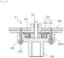
- FIG. 19 is a sectional view of an internal gear pump of the related art.
- this pump 21 is mainly composed of a trochoid 24 in which an inner rotor 23 having a plurality of external teeth is accommodated in an annular outer rotor 22 having a plurality of internal teeth.
- the trochoid 24 is rotatably accommodated in a circular trochoid accommodation recessed part 25a formed in a columnar casing 25 with a flange.
- a cover 26 is fixed to the casing 25 to close the trochoid accommodation recessed part 25a.
- the trochoid 24 is configured in such a manner that the external teeth of the inner rotor 23 are engaged with the internal teeth of the outer rotor 22 and the inner rotor 23 is rotatably accommodated in the outer rotor 22 in an eccentric state.
- a volume chamber on a suction-side and a discharge-side is formed between partition points, where the rotors come into contact with each other, in accordance with the rotation direction of the trochoid 24.
- a driving shaft 27 rotated by a driving source (not illustrated) penetrates and is fixed to an axial center of the inner rotor 23.
- an internal gear pump that is intended to send lubricant oil to a sliding part such as a compression part and a sliding bearing supporting a driving shaft like a scroll type compressor
- the lubrication state of the sliding part is designed to ensure a discharge flow rate required in the low-speed rotation.
- the flow rate of liquid to be discharged according to the rotation of the driving shaft is approximately proportional to the number of rotations, the flow rate is increased and oil is oversupplied in the high-speed rotation in view of the aforementioned design, which is not preferable in terms of the efficiency and the like of the compressor.
- Patent Literature 3 proposes an internal gear pump in which a liquid discharge groove (a bypass passage) for partially discharging liquid in a trochoid accommodation space to the exterior is provided to a slide part between a driving shaft and a slide bearing for supporting the driving shaft.
- the type of the mechanism may lead to an increase in size and weight. Furthermore, since the amount of discharge depends on a groove shape, a groove position, and the like, it is not easy to finely adjust an oil discharge amount and discharge pressure of excess supply during the high-speed rotation.
- a relief mechanism a mechanism that liberates discharge pressure by using a plunger and the like when the discharge pressure reaches predetermined pressure
- a general pump and the like are manufactured by cutting or a case where they are formed integrally with other pump members by cutting. In such a case, the manufacturing cost is increased, and partial replacement of the relief mechanism is not easy at the time of the occurrence of malfunction.
- An object of the present invention is, in order to solve such a problem, to provide an internal gear pump capable of suppressing a liquid discharge amount during a high-speed rotation by controlling discharge pressure while achieving reduction in size, weight, cost, and the like.
- An internal gear pump including a trochoid in which an inner rotor having a plurality of external teeth is accommodated inside an outer rotor having a plurality of internal teeth in an eccentrically rotatable manner with the external teeth and the internal teeth interdigitated with each other, and a suction-side volume chamber for sucking liquid and a discharge-side volume chamber for discharging the liquid sucked into the suction-side volume chamber are formed between the internal teeth and the external teeth, includes: a casing formed with a recessed part for accommodating the trochoid; and a cover that closes the recessed part of the casing, wherein an ejector is provided to communicate with a flow passage of the liquid formed on a bottom surface of the recessed part and to partially discharge the liquid in an accommodation space (simply referred to as a "pump inside”) of the trochoid formed by the casing and the cover.
- the ejector includes: a housing; a cylindrical body provided in the housing; and an elastic body that presses the cylindrical body in a direction opposite to pressure of the liquid in the flow passage of the liquid, wherein the liquid is partially discharged from a discharge flow passage between the cylindrical body and the housing formed when the elastic body is contracted in a direction opposite to the pressing direction by the pressure of the liquid via the cylindrical body, and the housing and the cylindrical body include a resin body.
- a through hole communicating with the ejector is provided in a part of the flow passage of the liquid formed on the bottom surface of the recessed part, and a chamfered portion of an end portion of the cylindrical body is pressed to a chamfered portion of the through hole facing a side of the ejector.
- An inner side surface of the recessed part of the casing includes a resin body, the bottom surface of the recessed part includes a metal body, and the ejector is fixed to the metal body.
- the casing includes a liquid suction part forming a part of a flow passage to the suction-side volume chamber of the liquid, and in the casing, a part including the recessed part and a part including the liquid suction part are configured separately from each other.
- the internal gear pump includes a suction port for introducing the liquid inside the accommodation space of the trochoid and the ejector on the bottom surface of the recessed part, and the ejector is configured to partially discharge the liquid from the suction port through a discharge flow passage by forming the discharge flow passage communicating the flow passage and the suction port in accordance with pressure of the liquid.
- the inner side surface of the recessed part of the casing includes a resin body, the bottom surface of the recessed part includes a metal plate embedded in the resin body of the casing, and the ejector is installed within a thickness of the metal plate.
- the ejector includes: a cylindrical body; and an elastic body that presses the cylindrical body in a direction opposite to the pressure of the liquid in the flow passage of the liquid and is a horizontal direction of the metal plate, wherein the elastic body is deformed by the pressure of the liquid via the cylindrical body, so that the pressing is released and the discharge flow passage is formed.
- the elastic body includes a coil spring, a torsion spring, a leaf spring, or a tension spring.
- the cylindrical body is made of a resin and the elastic body does not come into contact with the outer rotor and the inner rotor.
- a through hole communicating with the ejector is provided in a part of the flow passage of the liquid formed on the bottom surface of the recessed part, and in a state in which the pressing is not released, a tapered portion of the cylindrical body is pressed to an inclined portion of the through hole facing a side of the ejector, so that the flow passage is sealed by surface contact.
- At least one member of the casing and the cover includes a molded body of a resin composition, and the casing and the cover are fixed by fitting a plurality of protrusion parts protruding from one member to the other member.
- the casing and the cover are integrated with each other by a fixing member passing through a metal bush across the casing and the cover, and at least one of the protrusion parts is a protrusion part of the metal bush protruding from one member of the casing and the cover and fixed to the one member.
- At least one of the protrusion parts is a claw part protruding as a part of the molded body in one member of the casing and the cover.
- the resin composition is a resin composition in which a polyphenylene sulfide (PPS) resin is used as a base resin, and at least one selected from a glass fiber, a carbon fiber, and an inorganic filler is blended in the polyphenylene sulfide resin.
- PPS polyphenylene sulfide
- the internal gear pump according to the present invention is provided with the ejector that communicates with the flow passage of the liquid formed on the bottom surface of the recessed part accommodating the trochoid and partially discharges the liquid in the pump formed by the casing and the cover, so that it is possible to partially discharge the liquid in the pump and to suppress excess liquid supply during a high-speed rotation. Furthermore, it is possible to achieve reduction in size and weight compared to a case where a bypass passage is formed.
- the ejector includes a housing, a cylindrical body provided in the housing, and an elastic body that presses the cylindrical body in a direction opposite to pressure of the liquid in the liquid flow passage, and the liquid is partially discharged from a discharge flow passage between the cylindrical body and the housing formed when the elastic body is contracted in a direction opposite to the pressing direction by the pressure of the liquid via the cylindrical body, so that a discharge amount can be constantly held by liberating discharge pressure in the pump when the discharge pressure reaches a certain level. In this way, it is possible to stabilize the discharge amount by controlling the discharge pressure during a high-speed rotation, and to prevent oversupply of oil to the compressor. Furthermore, in the ejector, since the housing and the cylindrical body include a resin body, the pump can be made smaller and lighter. In particular, the housing and the cylindrical body include an injection molded body, so that cutting and the like are not required and the ejector can be easily manufactured at a low cost.
- the through hole communicating with the ejector is provided in a part of the liquid flow passage formed on the bottom surface of the recessed part, and the chamfered portion of the end portion of the cylindrical body is pressed to the chamfered portion of the through hole facing a side of the ejector, when the ejector is closed (when the cylindrical body is not lowered), it is possible to prevent the liquid from being leaked from the liquid flow passage to the discharge flow passage. In this way, it is possible to accurately control the discharge pressure.
- the inner side surface of the recessed part of the casing includes a resin body and the bottom surface of the recessed part includes a metal body, so that it is possible to improve friction and abrasion properties on inner side surface and to suppress the variation of the discharge performance on the bottom surface.
- the casing includes the liquid suction part forming a part of the flow passage to the suction-side volume chamber of the liquid, and in the casing, a part including the trochoid accommodation recessed part and a part including the liquid suction part are configured separately from each other, the fitting performance of the ejector is improved, so that it is possible to easily manufacture the pump having the aforementioned configuration.
- the internal gear pump forms the liquid flow passage on the bottom surface of the recessed part accommodating the trochoid and includes the suction port for introducing liquid inside the trochoid accommodation space and the ejector on the bottom surface, and the ejector is configured to partially discharge the liquid from the suction port through the discharge flow passage by forming the discharge flow passage communicating the flow passage and the suction port in accordance with pressure of the liquid, so that it is possible to partially discharge the liquid in the pump, to suppress excess liquid supply during a high-speed rotation, and to prevent burning.
- the ejector is provided by the improvement of the internal structure using a part of the existing suction port as a discharge port, so that the number of parts is decreased and it is possible to meet the requirement of the space saving.
- the bottom surface of the recessed part of the casing includes the metal plate embedded in the resin body of the casing and the ejector is installed within a thickness of the metal plate, so that it is not necessary to change an external appearance or a size compared to the existing product.
- the ejector includes a cylindrical body, and an elastic body that presses the cylindrical body in a direction opposite to the pressure of the liquid in the flow passage of the liquid and is a horizontal direction of the metal plate, and the elastic body is deformed by the pressure of the liquid via the cylindrical body, so that the pressing is released and the discharge flow passage is formed. Consequently, the discharge amount can be constantly held by liberating the discharge pressure in the pump when the discharge pressure reaches a certain level. In this way, it is possible to stabilize the discharge amount by controlling the discharge pressure during a high-speed rotation, and to prevent oversupply of oil to the compressor.
- the cylindrical body is made of a resin and the elastic body does not come into contact with the outer rotor and the inner rotor, even when a metal spring and the like are used as the elastic body, it is possible to prevent abrasion of each rotor, deterioration of the relief mechanism, and the like.
- the through hole communicating with the ejector is provided in a part of the flow passage of the liquid formed on the bottom surface of the recessed part, and in a state in which the pressing of the cylindrical body is not released, the tapered portion of the cylindrical body is pressed to the inclined portion of the through hole facing a side of the ejector, so that the flow passage is sealed by surface contact. Consequently, in the state (that is, in a state in which the ejector is closed), it is possible to prevent the liquid from being leaked from the liquid flow passage to the discharge flow passage. In this way, it is possible to accurately control the discharge pressure.
- At least one member of the casing and the cover includes a molded body of a resin composition, and the casing and the cover are fixed by fitting a plurality of protrusion parts protruding from one member to the other member, so that positioning during assembling is facilitated, it is possible to prevent separation or falling off of these two members, and workability is improved.
- the casing and the cover are integrated with each other by the fixing member passing through the metal bush across the casing and the cover and at least one of the protrusion parts is a protrusion part of the metal bush protruding from one member of the casing and the cover and fixed to the one member, when the casing and the cover are assembled, it is possible to facilitate the positioning of the casing and the cover by fitting the protrusion part of the metal bush in one member to the fitting part for the protrusion part of the other member. Furthermore, the strength of the fastening part of the casing and the cover is improved by the metal bush and it is possible to prevent the loosening of the fastening part due to the creep deformation of a resin.
- the claw part protruding as a part of the molded body in one member of the casing and the cover, the claw part is also a part of the resin molded body, is easily elastically deformed, and is superior in toughness, and it is possible to prevent breakage and the like during assembling.
- the resin composition is a resin composition in which a PPS resin is used as a base resin and at least one selected from a glass fiber, a carbon fiber, and an inorganic filler is blended in the PPS resin, it is superior in dimensional accuracy or toughness and the aforementioned effect is easily obtained. Furthermore, it is superior in oil resistance and chemical resistance, and can also be used in a high temperature atmosphere exceeding 120°C of a compressor and the like.
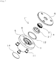
- FIG. 1 illustrates an assembled perspective view of the internal gear pump
- Fig. 2 illustrates an axial sectional view of the internal gear pump. As illustrated in Fig. 1 and Fig.
- the internal gear pump 1 includes a trochoid 4 in which an inner rotor 3 is accommodated in an annular outer rotor 2, a pump casing 5a formed with a circular recessed part (a trochoid accommodation recessed part) 8 for rotatably accommodating the trochoid 4, a suction casing 5b formed with a liquid suction part 5c, and a cover 6 that closes the trochoid accommodation recessed part 8 of the pump casing 5a.
- the cover 6 has a shape coinciding with an outer shape of an upper surface of a casing 5 in which the trochoid accommodation recessed part 8 is opened.
- the casing 5 is composed of the pump casing 5a and the suction casing 5b. As illustrated in Fig.
- the pump casing 5a, the suction casing 5b, and the cover 6 are integrated with one another by a fixing screw 13 passing through a bush 11, and are fastened and fixed to a plate (not illustrated) of the device body. Furthermore, the internal gear pump 1 has a driving shaft 10 fixed coaxially to the rotation center of the inner rotor 3.
- the number of external teeth of the inner rotor 3 is smaller than that of internal teeth of the outer rotor 2 by 1, and the inner rotor 3 is accommodated in the outer rotor 2 in an eccentric state in which the external teeth are inscribed in and interdigitated with the internal teeth.
- a volume chamber on a suction-side and a discharge-side is formed between partition points, where the rotors come into contact with each other, in accordance with the rotation direction of the trochoid 4.
- a bottom surface 8a of the trochoid accommodation recessed part 8 of the casing 5 is provided with a liquid flow passage 15 including a suction port communicating with the volume chamber on the suction side and a discharge port communicating with the volume chamber on the discharge side. Liquid is pumped from the discharge port to a compression part (not illustrated) at an upper side in the drawing through a discharge flow passage at the center of the driving shaft 10.
- liquid is sucked from the suction port into the suction-side volume chamber of the pump, where its volume is increased and a negative pressure state is reached due to the rotation of the trochoid 4 by the driving shaft 10.
- the suction-side volume chamber is changed to the discharge-side volume chamber where its volume is decreased and internal pressure is increased due to the rotation of the trochoid 4, so that the sucked liquid is discharged from the discharge-side volume chamber to the discharge port.
- the aforementioned pump operation is continuously performed by the rotation of the trochoid 4, so that liquid is continuously pumped.
- differential pressure between the volume chambers is increased, so that a large pump operation is obtained.
- the material of each member is not particularly limited, it is preferable that the inner side surface of the recessed part of the casing is made of a resin body and the bottom surface of the recessed part is made of a metal body.
- the pump casing 5a is in sliding contact with the outer rotor 2 and the inner rotor 3 at the bottom surface 8a and the inner side surface 8b constituting the trochoid accommodation recessed part 8.
- the inner side surface 8b of the trochoid accommodation recessed part 8 is made of a resin body, so that the friction and abrasion properties with the outer rotor 2 are improved.
- the bottom surface 8a of the trochoid accommodation recessed part 8 is composed of a disk-like metal plate 7 integrated with the pump casing 5a by composite molding. In this way, flatness is improved compared to a case where the bottom surface 8a is made of a resin, and it is possible to suppress the variation of discharge performance.
- the metal plate 7 it is possible to employ a sintered metal body or a molten metal body (a sheet-pressed component).
- the casing 5 is composed of two members of the pump casing 5a and the suction casing 5b, so that an ejector 9 to be described below is fixed to the pump casing 5a and then can be integrated with the suction casing 5b and the cover 6. In this way, the fitting performance of the ejector 9 is improved, so that it is possible to easily manufacture the pump having the ejector.
- the liquid suction part 5c is provided in the suction casing 5b.
- a filter 14 can be fixed to an end portion of the liquid suction part 5c serving as a communication passage inlet (a liquid suction port) up to the suction-side volume chamber by welding and the like. It is possible to prevent a foreign matter from entering the pump by the filter 14.
- the pump casing 5a As a material of the cover 6, the pump casing 5a, and the suction casing 5b, it is possible to use a metal (an iron, a stainless steel, a sintered metal, an aluminum alloy and the like) or a resin (a PPS resin, a polybutylene terephthalate (PBT) resin, a resin composition containing a filler blended in the PPS resin and the PBT resin, and a composite product of the metal and the resin may be used.
- a metal an iron, a stainless steel, a sintered metal, an aluminum alloy and the like
- a resin a PPS resin, a polybutylene terephthalate (PBT) resin, a resin composition containing a filler blended in the PPS resin and the PBT resin, and a composite product of the metal and the resin
- PPS resin polybutylene terephthalate
- a resin composition containing a filler blended in the PPS resin and the PBT resin a composite product of the metal
- a sintered metal an iron-based, a copper iron-based, a copper-based, a stainless-based metal, and the like
- the iron-based metal is more preferable in terms of cost.
- the stainless-based metal with high rust preventing capacity and the like are employed.
- the trochoid accommodation recessed part 8 is provided on the outer peripheral part thereof with a groove, and a seal ring 12 is assembled to the groove.
- a seal ring 12 is assembled to the groove.
- the liquid flow passage 15 is provided with the ejector 9 for partially discharging liquid in the accommodation space of the trochoid 4 to the exterior.
- the ejector 9 includes a housing 9a, a cylindrical body 9c provided in the housing 9a, and a spring 9b serving as an elastic body pressing the cylindrical body 9c in a direction toward the inside of the pump.
- the direction toward the inside of the pump is a direction opposite to the pressure of liquid in the liquid flow passage.
- a diameter of the cylindrical body 9c, which faces the spring side, is smaller than that of the inside of the pump, and the small diameter part is inserted and fitted to the spring 9b.
- An accommodation part of the housing 9a for accommodating the cylindrical body 9c is provided with a space where the cylindrical body 9c is displaceable by elastic deformation of the spring 9b. Furthermore, the metal plate 7 is formed with a through hole 7a for communicating the accommodation part of the cylindrical body of the ejector 9 and the liquid flow passage 15. The elastic force of the spring 9b can be adjusted by an adjustment screw 9g.
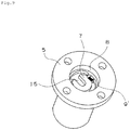
- FIG. 3 is a perspective view of a part including the pump casing (including the metal plate) and the ejector.
- the housing 9a of the ejector 9 is fixed to the metal plate 7 constituting the trochoid accommodation recessed part by fixing screws 9d.
- the cylindrical body 9c is pressed by the spring 9b so as to close the aforementioned through hole 7a.
- the through hole 7a is provided in the liquid flow passage 15 (see Fig. 2 ) including the discharge port communicating with the discharge-side volume chamber.
- the ejector 9 is fixed to an approximate center of the metal plate 7.
- the ejector 9 is configured not to interfere with a suction port 7b communicating with the suction-side volume chamber and the pump casing 5a. Furthermore, as illustrated in Fig. 2 , the ejector 9 is arranged inside the liquid suction part 5c of the suction casing 5b.
- FIG. 4 On the basis of Fig. 4 , the operation of the ejector will be described.
- (a) of Fig. 4 is an enlarged sectional view of the periphery of the ejector when no liquid is discharged
- (b) of Fig. 4 is an enlarged sectional view of the periphery of the ejector when liquid is discharged.
- the pressure (discharge pressure) of the liquid in the liquid flow passage 15 is applied to the end portion of the cylindrical body 9c, which faces the liquid flow passage 15 side.
- the spring 9b in the range in which the discharge pressure generated inside the pump does not exceed prescribed pressure (a setting value at which discharge is started), the spring 9b is not pushed and the cylindrical body 9c is pressed by the spring 9b so as to close the through hole 7a of the metal plate 7. Specifically, a chamfered portion 9e of the end portion of the cylindrical body 9c is pressed to a chamfered portion 7c of the through hole 7a, which faces the ejector side.
- FIG. 5 is a plan view illustrating the housing of the ejector and
- FIG. 5 is a plan view illustrating a state in which the cylindrical body is accommodated in the housing.
- a gap is formed between the cylindrical body 9c and the housing 9a as the discharge flow passage 9f.
- the cylindrical body 9c and the housing 9a are made of a resin body.
- the resin body is a molded body of a resin composition, and is preferably an injection molded body of a resin composition.
- the resin is employed as a material, it is possible to achieve reduction in size and weight compared to metal cutting products. Furthermore, when the injection molded body of the resin is employed, it is possible to easily manufacture the ejector 9 at a low cost.
- an injection-moldable synthetic resin (base resin) constituting such a resin composition there are a thermoplastic polyimide resin, a polyether ketone (PEK) resin, a polyether ether ketone (PEEK) resin, a PPS resin, a polyamide-imide resin, a polyamide (PA) resin, a PBT resin, a polyethylene terephthalate (PET) resin, a polyethylene (PE) resin, a polyacetal resin, a phenol resin, and the like.
- These resins may be used alone or may be a polymer alloy in which two or more types of resins are mixed.
- it is more preferable to use the PPS resin because it is superior in creep resistance, load resistance, abrasion resistance, chemical resistance, and the like of molded body.
- a glass fiber, a carbon fiber, or an inorganic filler which is effective for high strength, high elasticity, high dimension accuracy, and imparting abrasion resistance and removing anisotropy of injection molding shrinkage, alone or in combination as appropriate.
- the combination of the glass fiber and the inorganic filler is superior in economic efficiency and is superior in friction and abrasion properties in oil.
- the cylindrical body is pressed to the metal plate and the like, it is preferable to employ the aforementioned resin material superior in abrasion resistance as the material of the cylindrical body.
- the ejector has been described on the basis of Fig. 1 to Fig. 5 ; however, the ejector according to the first embodiment is not limited thereto and any mechanism can be employed that is fixable to the bottom surface side of the trochoid accommodation recessed part and is configured to partially discharge liquid in the trochoid accommodation space by communicating with the liquid flow passage formed on the bottom surface.
- Fig. 6 illustrates a relation between the number of rotations and the discharge flow rate in the internal gear pump.
- a change in the relation between the number of rotations and the discharge flow rate was evaluated in the pump (the present invention in the drawing) including the ejection structure ( Fig. 1 to Fig. 5 ) according to the first embodiment and the pump (the related art in the drawing) in which only the ejection structure is not provided and the other configurations are the same.
- the number of rotations and the discharge amount are roughly directly proportional to each other.
- the discharge amount increases in the high-speed rotation region (after 8000 rotations), but in the pump according to the first embodiment, the discharge amount is approximately constant in the equivalent high-speed rotation region.
- the ejector operates (the cylindrical body is pushed) in the high-speed rotation region and excess oil is discharged in the pump according to the first embodiment.
- an internal gear pump such as a scroll type compressor
- the flow rate is likely to increase during the high-speed rotation, and when there is no ejector as in the related art, oil may be oversupplied.
- the liquid in the pump can be partially discharged to the exterior by the ejector, so that it is possible to suppress excess liquid supply during the high-speed rotation.
- the internal gear pump 1' includes a trochoid 4 in which an inner rotor 3 is accommodated in an annular outer rotor 2, a casing 5 formed with a circular recessed part (a trochoid accommodation recessed part) 8 for rotatably accommodating the trochoid 4, and a cover 6 that closes the trochoid accommodation recessed part 8 of the casing 5.
- the casing 5 is composed of one member.
- the cover 6 has a shape coinciding with an outer shape of an upper surface of the casing 5 in which the trochoid accommodation recessed part 8 is opened.
- the casing 5 and the cover 6 are integrated with each other by a fixing screw 13 passing through a bush 11, and are fastened and fixed to the plate (not illustrated) of the device body.
- the bottom surface 8a of the trochoid accommodation recessed part 8 of the casing 5 is provided with a suction port 7b (see Fig. 10 ) communicating with a volume chamber on a suction side, a discharge port communicating with a volume chamber on a discharge side, and a liquid flow passage 15. Liquid is pumped from the discharge port to a compression part (not illustrated) at an upper side in the drawing through a discharge flow passage at the center of a driving shaft 10.
- the other basic configurations of the pump are the same as those in the first embodiment.
- the internal gear pump 1' as a material of the cover 6 and the casing 5, similarly to the first embodiment, it is possible to use a metal or a resin, and a composite product of the metal and the resin may be used. Furthermore, it is preferable to use a sintered metal (an iron-based, a copper iron-based, a copper-based, a stainless-based metal, and the like) as a material of the outer rotor and the inner rotor, and the iron-based metal is more preferable in terms of cost. In addition, in the trochoid pump that pumps water, chemical solution, and the like, it is sufficient if the stainless-based metal with high rust preventing capacity and the like are employed.
- the material of the aforementioned casing and the like is not particularly limited, it is preferable that the inner side surface of the recessed part of the casing is made of a resin body and the bottom surface of the recessed part is made of a metal body such as a metal plate.
- the casing 5 is in sliding contact with the outer rotor 2 and the inner rotor 3 at the bottom surface 8a and the inner side surface 8b constituting the trochoid accommodation recessed part 8.
- the inner side surface 8b of the trochoid accommodation recessed part 8 is made of a resin body, so that the friction and abrasion properties with the outer rotor 2 are improved.
- the liquid suction part 5c is provided in the casing 5.
- the casing 5 is made of a resin body, so that the liquid suction part 5c can also be integrally formed at the time of molding.
- the bottom surface 8a of the trochoid accommodation recessed part 8 is composed of the disk-like metal plate 7 integrally embedded in the resin body by composite molding with the casing 5. In this way, flatness is improved compared to a case where the bottom surface 8a is made of a resin, and it is possible to suppress the variation of discharge performance.
- the metal plate 7 it is possible to employ a sintered metal body or a molten metal body (a sheet-pressed component).
- the internal gear pump 1' has an ejector 9' for partially discharging liquid in the accommodation space of the trochoid.
- the ejector will be described on the basis of Fig. 9 to Fig. 11 .
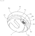
- Fig. 9 is a perspective view of the casing
- Fig. 10 is an enlarged view of the periphery of the ejector
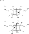
- Fig. 11 is a horizontal sectional view of the periphery of the ejector. As illustrated in Fig. 9 and Fig.
- the bottom surface 8a of the recessed part 8 of the casing 5 is provided with the suction port 7b for introducing liquid into the inside of the pump, the liquid flow passage 15, and the ejector 9' for partially discharging the liquid in the pump.
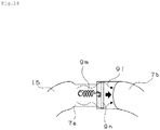
- the ejector 9' is configured to partially discharge the liquid from the suction port 7b through the discharge flow passage 9j by forming a discharge flow passage 9j communicating the liquid flow passage 15 and the suction port 7b in accordance with the pressure of the liquid.
- the discharge flow passage 9j is formed in the middle of the liquid flow passage 15 to partially recirculate the liquid to the suction port 7b.
- the discharge flow passage 9j is a flow passage that is temporarily formed by a relief mechanism, which is different from a normal liquid flow passage directed to the discharge port from the suction port 7b.
- the ejector 9' of this embodiment includes a cylindrical body 9h and a spring 9i for pressing the cylindrical body in a predetermined direction.
- the pressing direction is a direction opposite to the pressure of the liquid in the liquid flow passage 15 and is a horizontal direction of the metal plate 7.
- a diameter of the cylindrical body 9h, which faces the spring side, is smaller than that of the liquid flow passage 15 side, and the small diameter part is inserted and fitted to the spring 9i.
- An accommodation part of the metal plate 7 for accommodating the cylindrical body 9h is provided with a space where the cylindrical body 9h is displaceable by elastic deformation of the spring 9i.
- the metal plate 7 is formed with a through hole 7a for communicating a space where the cylindrical body 9h of the ejector 9' is accommodated and the liquid flow passage 15.
- the spring 9i is fitted and fixed to a spring fixing part 7d provided on the metal plate 7.
- the spring fixing part 7d is integrated with the metal plate 7 by post-processing and the like of the metal plate 7 and may be fixed by bonding, fitting, and the like of a separate member.
- the spring fixing part 7d is integrated with the metal plate 7 because the number of parts can be reduced and a failure rate is also lowered.
- the cylindrical body 9h is pressed by the spring 9i so as to close the through hole 7a.
- the pressure (discharge pressure) of the liquid in the liquid flow passage 15 is applied to the end portion of the cylindrical body 9h, which faces the liquid flow passage 15 side.
- the ejector 9' is installed within the thickness of the metal plate 7. Due to the structure of the space-saving ejector, the thickness of the metal plate 7 can be allowed to be constant regardless of the presence or absence of the ejector. Therefore, it is possible to appropriately employ the ejector without changing an external appearance or a size of the internal gear pump with the conventional structure and dimension. Furthermore, the ejector 9' has a structure in which only the cylindrical body 9h comes into contact with the outer rotor 2 or the inner rotor 3 and the spring 9i or the spring fixing part 7d do not come into contact with the outer rotor 2 or the inner rotor 3. In such a structure, the cylindrical body 9h is made of a resin body, so that it is possible to prevent abrasion of each rotor, deterioration of the relief mechanism, and the like.
- the cylindrical body 9h is made of a resin body as described above.
- the resin body is a molded body of a resin composition, and is preferably an injection molded body of a resin composition.
- the resin is employed as a material, it is easy to achieve reduction in size and weight and it is also superior in a sliding property.
- the injection molded body of the resin is employed, it is possible to easily manufacture the ejector 9' at a low cost.
- An injection-moldable synthetic resin (base resin) constituting such a resin composition is the same as that used for the cylindrical body 9c or the housing 9a of the ejector 9 according to the first embodiment, and it is more preferable to use the PPS resin because it is superior in creep resistance, abrasion resistance, chemical resistance, and the like of molded body.
- a glass fiber, a carbon fiber, or an inorganic filler which is effective for high strength, high elasticity, high dimension accuracy, and imparting abrasion resistance and removing anisotropy of injection molding shrinkage, alone or in combination as appropriate.
- the combination of the glass fiber and the inorganic filler is superior in economic efficiency and is superior in friction and abrasion properties in oil.
- each surface of the cylindrical body is in sliding contact with the metal plate or each rotor, it is preferable to employ the aforementioned resin material superior in abrasion resistance as the material of the cylindrical body.
- a lid may be provided on the ejector to separate the rotors from each other.
- the ejector may be disposed on the outer side (a part may protrude from the recessed part) of the bottom surface, or may be disposed in a position where the ejector is not in sliding contact with the inner rotor.
- the prescribed pressure can be set by specifying elastic force by a spring constant and a free length thereof. In this way, it is also possible to appropriately set a liquid discharge amount.
- the spring it is possible to employ a torsion spring, a leaf spring, or a tension spring, in addition to the coil spring illustrated in Fig. 9 to Fig. 11 .
- a rubber material and the like may be employed as the elastic body.
- Fig. 12 to Fig. 14 are schematic views of the periphery of the ejector.
- the ejector illustrated in (a) of Fig. 12 is an example in which the coil spring 9i is used as the elastic body similarly to Fig. 9 to Fig. 11 .
- the coil spring 9i is not pushed and the cylindrical body 9h is pressed by the coil spring 9i so as to close the through hole 7a of the metal plate.
- the ejector illustrated in (b) of Fig. 12 is an example in which a leaf spring 9k is used as the elastic body.
- the leaf spring 9k is provided by fixing its one end to the metal plate so as to close the through hole 7a of the metal plate. In the range in which the discharge pressure generated inside the pump does not exceed the prescribed pressure, the leaf spring 9k is not deformed and the through hole 7a is blocked. In this way, since the discharge flow passage 9j is not formed between the suction port 7b and the liquid flow passage 15, the liquid in the pump is not discharged. When the leaf spring receives the pressure of the liquid and is deformed such that a non-fixed side end portion is pushed, the discharge flow passage 9j is formed.
- the ejector illustrated in (a) of Fig. 13 is an example in which a separate leaf spring 9k is used as the elastic body.
- the leaf spring 9k is provided by fixing its both ends to the metal plate and supports the cylindrical body 9h.
- the cylindrical body 9h is pressed by the leaf spring 9k so as to close the through hole 7a of the metal plate.
- the leaf spring 9k is deformed, so that the discharge flow passage 9j is formed.
- the ejector illustrated in (b) of Fig. 13 is an example in which torsion springs 9l are used as the elastic body.
- Each torsion spring 9l is provided by fixing its one end to the metal plate, so that the two torsion springs 9l support the cylindrical body 9h from both end walls of the flow passage.
- the cylindrical body 9h is pressed by the torsion springs 9l so as to close the through hole 7a of the metal plate.
- the torsion springs 9l are deformed, so that the discharge flow passage 9j is formed.
- the ejector illustrated in Fig. 14 is an example in which a tension spring 9m is used as the elastic body.
- the tension spring 9m is provided by fixing its one end to a part of the flow passage of the metal plate and pulls a lid 9n against the pressure of the liquid. In the range in which the discharge pressure generated inside the pump does not exceed the prescribed pressure, the lid 9n is pulled by the tension spring 9m so as to close the through hole 7a of the metal plate. When the lid 9n is moved by the pressure of the liquid, the tension spring 9m is deformed, so that the discharge flow passage 9j is formed.
- the cylindrical body 9h forms a tapered portion and the like at its end portion facing the through hole 7a side and seals the flow passage by surface contact with an inclined portion formed at the edge of the through hole 7a. In this way, it is possible to prevent liquid from being leaked from the liquid flow passage 15 to the suction port 7b.
- the ejector has been described on the basis of Fig. 9 to Fig. 14 ; however, the ejector according to the second embodiment is not limited thereto and any means can be employed that is configured to partially discharge the liquid from the suction port through the discharge flow passage by forming the discharge flow passage communicating the liquid flow passage and the suction port in accordance with the pressure of liquid.
- the number of rotations and the discharge amount are roughly directly proportional to each other, and in the pump of the related art, the discharge amount tends to increase in the high-speed rotation region (after 8000 rotations) (see Fig. 6 ).
- an internal gear pump such as a scroll type compressor, since it is designed to ensure a discharge flow rate required in the low-speed rotation, the flow rate is likely to increase during the high-speed rotation, and when there is no ejector as in the related art, oil may be oversupplied.
- the liquid in the pump can be partially discharged to the exterior by the ejector, so that it is possible to suppress excess liquid supply during the high-speed rotation.
- the material of the casing and the cover it is possible to use a metal or a resin and the material is not particularly limited.
- a pump which can reduce a machining process and can be manufactured at a low cost a pump having a resin casing has been known.
- FIG. 19 A mounting structure of the casing and the cover in such a pump will be described using Fig. 19 .
- the cover 26 is made of a sintered metal and the casing 25 is an injection molded body manufactured by injection molding using a resin composition.
- the casing 25 and the cover 26 are fastened and fixed to a fixed plate 30 of an actual device by a bolt 29 passing through a metal bush 28 provided in the casing 25.
- the casing 25 and the cover 26 have a mutually flat planar shape and seal the trochoid accommodation recessed part 25a.
- such an internal gear pump is bolted in a state in which the resin casing and the metal cover overlap each other when being mounted on an actual device.
- a resin molded article has a low mechanical strength
- the strength of the fastening part is improved by insert-molding the aforementioned metal bush.
- a boundary surface between the casing and the cover is a plane, it is necessary to visually confirm a deviation and the like of a bolt hole in the metal bush on the casing side and the cover, and to perform the positioning of the casing and the cover.
- the housing and the cover may separate or may fall off. In particular, when being mounted on the actual device, the housing and the cover may fall off and workability may deteriorate due to the mounting posture of the pump.
- the casing and the cover are fixed by allowing a plurality of protruding parts protruding from one member to be fitted to the other member.
- the protruding part for example, a metal bush fixed to a resin casing may be used, or a claw part provided on a resin casing or cover may be used.
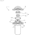
- Fig. 15 is an assembled perspective view of an example of the internal gear pump
- Fig. 16 is an axial sectional view of the internal gear pump.
- the internal gear pump 1" illustrated in Fig. 15 and Fig. 16 is a pump which does not have the aforementioned ejector (for example, the ejector 9 or the ejector 9').
- the internal gear pump 1" includes a trochoid 4 in which an inner rotor 3 is accommodated in an annular outer rotor 2, a pump casing 5a formed with a circular recessed part (a trochoid accommodation recessed part) 8 for rotatably accommodating the trochoid 4, a suction casing 5b formed with a liquid suction part 5c, and a cover 6 that closes the trochoid accommodation recessed part 8 of the pump casing 5a.
- a casing 5 is composed of two members of the pump casing 5a and a suction casing 5b. Three metal bushes 16 are fixed to the suction casing 5b. As illustrated in Fig.
- bolts 13 are fixing members passing through the metal bushes 16 across the casings and cover, and integrated with one another.
- the fixing member is not limited to the bolt 13, and any members may be used if they can fix each member and for example, a screw, a pin, and the like may be used.
- the bottom surface 8a of the trochoid accommodation recessed part 8 of the casing 5 is provided with a liquid flow passage including a suction port communicating with a volume chamber on a suction side and a discharge port communicating with a volume chamber on a discharge side. Liquid is pumped from the discharge port to a compression part (not illustrated) at an upper side in the drawing through a discharge flow passage at the center of a driving shaft 10.
- the other basic configurations of the pump are the same as those in the first embodiment.
- the internal gear pump according to the third embodiment at least one member of the casing and the cover is a molded body (a resin body) of a resin composition.
- the internal gear pump according to the third embodiment has a configuration employing such a resin casing and the like, facilitates the positioning of the casing and the cover during assembling, and prevents separation or falling off of these two members.
- the almost whole of the casing 5 and the cover 6, that is, the cover 6, the pump casing 5a, and the suction casing 5b are made of a resin body and are integrated with one another by the metal bush 16 and the bolt 13.
- a member for fixing at least the metal bush 16 is a resin body, and for example, the cover 6 may be made of a metal (iron, a stainless steel, a sintered metal, an aluminum alloy, and the like).
- the metal bush 16 is fixed to a flange part 5d of the suction casing 5b.
- a protruding part of the metal bush 16 from the suction casing 5b is allowed to be fitted to a fitting part 5e of the pump casing 5a and a fitting part 6a of the cover 6, so that it is possible to facilitate the positions of these members.
- the metal bush 16 even when one or both of the casing 5 and the cover 6 is made of a resin body, it is possible to improve the strength of the fastening parts of both members and to prevent the loosening of the fastening part due to the creep deformation of a resin.
- the length of the metal bush 16 is adjusted such that the distal end of the metal bush 16 during assembling does not protrude from the upper end surface 6b of the fitting part 6a of the cover 6. More preferably, the distal end of the metal bush 16 is shaped to be recessed from the upper end surface 6b of the fitting part 6a of the cover 6. In this way, it is possible to prevent interference between the fixed plate of an actual device and the metal bush 16.
- the metal bush 16 can be made of an arbitrary metal such as an iron, a stainless steel, and a sintered metal; preferably, the metal bush 16 is made of the sintered metal.
- the metal bush is made of the sintered metal and is subjected to composite molding (insert molding) with the suction casing, since the resin enters the recess of the surface of the sintered metal of the bush, it is firmly bonded by an anchor effect. In this way, even when the metal bush is designed to protrude longer from the injection molded body such as the casing, it is possible to prevent detachment of the metal bush during transport or mounting.
- the inner side surface of the trochoid accommodation recessed part is made of a resin body and the bottom surface of the recessed part is made of a metal body.
- the pump casing 5a is in sliding contact with the outer rotor 2 and the inner rotor 3 at the bottom surface 8a and the inner side surface 8b constituting the trochoid accommodation recessed part 8.
- the inner side surface 8b of the trochoid accommodation recessed part 8 is made of a resin body, so that the friction and abrasion properties with the outer rotor 2 are improved.
- the bottom surface 8a of the trochoid accommodation recessed part 8 is composed of a disk-like metal plate 7 integrated with the pump casing 5a by composite molding.
- the metal plate 7 it is possible to employ a sintered metal body or a molten metal body (a sheet-pressed component).
- the casing 5 is composed of two members of the pump casing 5a and the suction casing 5b, so that the aforementioned composite molding (insert molding) of the metal plate 7 is facilitated.
- the third embodiment even when the number of parts is increased by separating the casing into a plurality of members, positioning is facilitated and assembling performance is improved due to a fitting structure using a plurality of protruding parts.
- the internal gear pump 1"' includes a trochoid 4 in which an inner rotor 3 is accommodated in an annular outer rotor 2, a casing 5 formed with a trochoid accommodation recessed part 8, and a cover 6 that closes the trochoid accommodation recessed part 8.
- the cover 6 has a shape coinciding with an outer shape of an upper surface of a casing 5 in which the trochoid accommodation recessed part 8 is opened.
- the casing 5 is made of a resin.
- the casing 5 and the cover 6 are fixed to a fixed plate of an actual device with bolts (not illustrated) passing through the metal bushes 16 fixed to the casing 5, and integrated with one another.
- the other basic configurations of the pump are the same as those illustrated in Fig. 15 and Fig. 16 .
- the metal bush 16 is not fitted to the cover 6.
- the casing 5 is provided with four claw parts 17 protruding therefrom. These claw parts 17 are integrated with the casing 5 and are formed simultaneously with the molding of the resin casing 5. As illustrated in Fig. 18 , at the time of assembling, the claw parts 17 are fitted (engaged) so as to hold an outer peripheral portion of the cover 6, so that positioning can be easily performed. Furthermore, since the claw part is made of a resin, it is easy to be elastically deformed and is superior in toughness, and it is possible to prevent breakage and the like during assembling. In addition, the shape or the number of the claw parts 17 is not particularly limited if the positioning of both members is possible.
- a resin composition forming the casing or the cover mainly employs an injection-moldable synthetic resin as a base resin.
- the base resin for example, there are a PPS resin, a thermoplastic polyimide resin, a PEK resin, a PEEK resin, a polyamide-imide resin, a PA resin, a PBT resin, a PET resin, a PE resin, a polyacetal resin, a phenol resin, and the like.
- These resins may be used alone or may be a polymer alloy in which two or more types of resins are mixed.
- it is more preferable to use the PPS resin because it is superior in creep resistance, load resistance, abrasion resistance, chemical resistance, and the like of molded body.
- a glass fiber, a carbon fiber, or an inorganic filler which is effective for high strength, high elasticity, high dimension accuracy, and imparting abrasion resistance and removing anisotropy of injection molding shrinkage, alone or in combination as appropriate.
- the combination of the glass fiber and the inorganic filler is superior in economic efficiency and is superior in friction and abrasion properties in oil.
- the third embodiment it is more preferable to use a resin composition in which the straight-chain type PPS resin is used as a base resin and glass fibers and glass beads are blended in the base resin as a filler. Since this structure is superior in oil resistance, chemical resistance, and toughness, has a small warpage due to removal of the anisotropy of injection molding shrinkage, and significantly improves dimensional accuracy, it is particularly effective when both of the cover and the casing are made of a resin.
- the casing or the cover is molded by injection molding using molding pellets obtained from these raw materials.
- the aforementioned metal bush is arranged in a mold and is integrated by composite molding when the suction casing is molded. Furthermore, when the pump casing is molded, the aforementioned metal bush is arranged in a mold and is integrated by composite molding.
- the internal gear pump according to the third embodiment as a material of the outer rotor and the inner rotor, it is preferable to use a sintered metal (an iron-based, a copper iron-based, a copper-based, a stainless-based metal, and the like), and the iron-based metal is more preferable in terms of cost.
- a sintered metal an iron-based, a copper iron-based, a copper-based, a stainless-based metal, and the like
- the iron-based metal is more preferable in terms of cost.
- the stainless-based metal with high rust preventing capacity and the like are employed.
- the internal gear pump according to the third embodiment is not limited thereto.
- both of the metal bush and the claw part may be used.
- the ejector 9 according to the first embodiment or the ejector 9' according to the second embodiment may also be provided in the internal gear pump illustrated in Fig. 15 to Fig. 18 . In this way, it is possible to partially discharge liquid in the pump to the exterior by the ejector and to suppress excess liquid supply during the high-speed rotation while facilitating positioning at the time of assembling.
- the internal gear pump according to the present invention can suppress a liquid discharge amount during a high-speed rotation by controlling discharge pressure while achieving reduction in size, weight, cost, and the like, so that it can be used as an internal gear pump (a trochoid pump) that pumps liquid such as oil, water, and chemical solution.
- the internal gear pump can be suitably used as a pump for supplying liquid to sliding parts of a scroll type compressor for an electric hot-water supply machine, a room air conditioner, or a car air conditioner, which uses alternatives for chlorofluorocarbon, carbon dioxide, and the like as a refrigerant.
Landscapes
- Engineering & Computer Science (AREA)
- Mechanical Engineering (AREA)
- General Engineering & Computer Science (AREA)
- Rotary Pumps (AREA)
- Details And Applications Of Rotary Liquid Pumps (AREA)
Abstract
Description
- The present invention relates to an internal gear pump (a trochoid pump) that pumps liquid such as oil, water, and chemical solution, and more particularly, to an internal gear pump used in an industrial machinery field, for example, an air conditioning compressor.
- An internal gear pump (a trochoid pump) is a pump in which an outer rotor and an inner rotor having a trochoid tooth profile are accommodated in a casing in a sealed state, and the inner rotor and the outer rotor fixed to a driving shaft rotate together with the rotation of the driving shaft, so that liquid is sucked and discharged. As such a type of pump, for example,
Patent Literature 1 has been proposed. In recent years, as a pump which can reduce a machining process and can be manufactured at a low cost, a pump having a resin casing has been known (see Patent Literature 2). - On the basis of
Fig. 19 , the structure of such a type of internal gear pump will be described.Fig. 19 is a sectional view of an internal gear pump of the related art. As illustrated inFig. 19 , thispump 21 is mainly composed of atrochoid 24 in which aninner rotor 23 having a plurality of external teeth is accommodated in an annularouter rotor 22 having a plurality of internal teeth. Thetrochoid 24 is rotatably accommodated in a circular trochoid accommodation recessed part 25a formed in acolumnar casing 25 with a flange. Acover 26 is fixed to thecasing 25 to close the trochoid accommodation recessed part 25a. - The
trochoid 24 is configured in such a manner that the external teeth of theinner rotor 23 are engaged with the internal teeth of theouter rotor 22 and theinner rotor 23 is rotatably accommodated in theouter rotor 22 in an eccentric state. A volume chamber on a suction-side and a discharge-side is formed between partition points, where the rotors come into contact with each other, in accordance with the rotation direction of thetrochoid 24. Adriving shaft 27 rotated by a driving source (not illustrated) penetrates and is fixed to an axial center of theinner rotor 23. When theinner rotor 23 rotates by the rotation of thedriving shaft 27, since the external teeth are engaged with the internal teeth of theouter rotor 22 and theouter rotor 22 rotates in the same direction, liquid is sucked from a suction port into the suction-side volume chamber where its volume is increased due to the rotation and a negative pressure state is reached. Then, the suction-side volume chamber is changed to the discharge-side volume chamber where the volume is decreased by the rotation of thetrochoid 24 and internal pressure is increased, so that the sucked liquid is discharged from the discharge-side volume chamber to a discharge port. - In an internal gear pump that is intended to send lubricant oil to a sliding part such as a compression part and a sliding bearing supporting a driving shaft like a scroll type compressor, since it is difficult to form an oil film in a lower speed rotation than a higher speed rotation, the lubrication state of the sliding part is designed to ensure a discharge flow rate required in the low-speed rotation. In the internal gear pump, since the flow rate of liquid to be discharged according to the rotation of the driving shaft is approximately proportional to the number of rotations, the flow rate is increased and oil is oversupplied in the high-speed rotation in view of the aforementioned design, which is not preferable in terms of the efficiency and the like of the compressor. In order to solve such a problem, for example,
Patent Literature 3 proposes an internal gear pump in which a liquid discharge groove (a bypass passage) for partially discharging liquid in a trochoid accommodation space to the exterior is provided to a slide part between a driving shaft and a slide bearing for supporting the driving shaft. -
- Patent Literature 1:
JP 4215160 - Patent Literature 2:
JP 2014-51964 - Patent Literature 3:
JP 2015-183631 - However, in the case of employing the mechanism that provides the bypass passage and allows the bypass passage to be communicated, the type of the mechanism may lead to an increase in size and weight. Furthermore, since the amount of discharge depends on a groove shape, a groove position, and the like, it is not easy to finely adjust an oil discharge amount and discharge pressure of excess supply during the high-speed rotation.
- In addition, there is a case where all parts constituting a relief mechanism (a mechanism that liberates discharge pressure by using a plunger and the like when the discharge pressure reaches predetermined pressure) used in a general pump and the like are manufactured by cutting or a case where they are formed integrally with other pump members by cutting. In such a case, the manufacturing cost is increased, and partial replacement of the relief mechanism is not easy at the time of the occurrence of malfunction.
- An object of the present invention is, in order to solve such a problem, to provide an internal gear pump capable of suppressing a liquid discharge amount during a high-speed rotation by controlling discharge pressure while achieving reduction in size, weight, cost, and the like.
- An internal gear pump according to the present invention including a trochoid in which an inner rotor having a plurality of external teeth is accommodated inside an outer rotor having a plurality of internal teeth in an eccentrically rotatable manner with the external teeth and the internal teeth interdigitated with each other, and a suction-side volume chamber for sucking liquid and a discharge-side volume chamber for discharging the liquid sucked into the suction-side volume chamber are formed between the internal teeth and the external teeth, includes: a casing formed with a recessed part for accommodating the trochoid; and a cover that closes the recessed part of the casing, wherein an ejector is provided to communicate with a flow passage of the liquid formed on a bottom surface of the recessed part and to partially discharge the liquid in an accommodation space (simply referred to as a "pump inside") of the trochoid formed by the casing and the cover.
- The ejector includes: a housing; a cylindrical body provided in the housing; and an elastic body that presses the cylindrical body in a direction opposite to pressure of the liquid in the flow passage of the liquid, wherein the liquid is partially discharged from a discharge flow passage between the cylindrical body and the housing formed when the elastic body is contracted in a direction opposite to the pressing direction by the pressure of the liquid via the cylindrical body, and the housing and the cylindrical body include a resin body.
- A through hole communicating with the ejector is provided in a part of the flow passage of the liquid formed on the bottom surface of the recessed part, and a chamfered portion of an end portion of the cylindrical body is pressed to a chamfered portion of the through hole facing a side of the ejector.
- An inner side surface of the recessed part of the casing includes a resin body, the bottom surface of the recessed part includes a metal body, and the ejector is fixed to the metal body.
- The casing includes a liquid suction part forming a part of a flow passage to the suction-side volume chamber of the liquid, and in the casing, a part including the recessed part and a part including the liquid suction part are configured separately from each other.
- The internal gear pump includes a suction port for introducing the liquid inside the accommodation space of the trochoid and the ejector on the bottom surface of the recessed part, and the ejector is configured to partially discharge the liquid from the suction port through a discharge flow passage by forming the discharge flow passage communicating the flow passage and the suction port in accordance with pressure of the liquid.
- The inner side surface of the recessed part of the casing includes a resin body, the bottom surface of the recessed part includes a metal plate embedded in the resin body of the casing, and the ejector is installed within a thickness of the metal plate.
- The ejector includes: a cylindrical body; and an elastic body that presses the cylindrical body in a direction opposite to the pressure of the liquid in the flow passage of the liquid and is a horizontal direction of the metal plate, wherein the elastic body is deformed by the pressure of the liquid via the cylindrical body, so that the pressing is released and the discharge flow passage is formed. In particular, the elastic body includes a coil spring, a torsion spring, a leaf spring, or a tension spring.
- The cylindrical body is made of a resin and the elastic body does not come into contact with the outer rotor and the inner rotor.
- A through hole communicating with the ejector is provided in a part of the flow passage of the liquid formed on the bottom surface of the recessed part, and in a state in which the pressing is not released, a tapered portion of the cylindrical body is pressed to an inclined portion of the through hole facing a side of the ejector, so that the flow passage is sealed by surface contact.
- At least one member of the casing and the cover includes a molded body of a resin composition, and the casing and the cover are fixed by fitting a plurality of protrusion parts protruding from one member to the other member.
- The casing and the cover are integrated with each other by a fixing member passing through a metal bush across the casing and the cover, and at least one of the protrusion parts is a protrusion part of the metal bush protruding from one member of the casing and the cover and fixed to the one member.
- At least one of the protrusion parts is a claw part protruding as a part of the molded body in one member of the casing and the cover.
- The resin composition is a resin composition in which a polyphenylene sulfide (PPS) resin is used as a base resin, and at least one selected from a glass fiber, a carbon fiber, and an inorganic filler is blended in the polyphenylene sulfide resin.
- The internal gear pump according to the present invention is provided with the ejector that communicates with the flow passage of the liquid formed on the bottom surface of the recessed part accommodating the trochoid and partially discharges the liquid in the pump formed by the casing and the cover, so that it is possible to partially discharge the liquid in the pump and to suppress excess liquid supply during a high-speed rotation. Furthermore, it is possible to achieve reduction in size and weight compared to a case where a bypass passage is formed.
- Furthermore, the ejector includes a housing, a cylindrical body provided in the housing, and an elastic body that presses the cylindrical body in a direction opposite to pressure of the liquid in the liquid flow passage, and the liquid is partially discharged from a discharge flow passage between the cylindrical body and the housing formed when the elastic body is contracted in a direction opposite to the pressing direction by the pressure of the liquid via the cylindrical body, so that a discharge amount can be constantly held by liberating discharge pressure in the pump when the discharge pressure reaches a certain level. In this way, it is possible to stabilize the discharge amount by controlling the discharge pressure during a high-speed rotation, and to prevent oversupply of oil to the compressor. Furthermore, in the ejector, since the housing and the cylindrical body include a resin body, the pump can be made smaller and lighter. In particular, the housing and the cylindrical body include an injection molded body, so that cutting and the like are not required and the ejector can be easily manufactured at a low cost.
- Since the through hole communicating with the ejector is provided in a part of the liquid flow passage formed on the bottom surface of the recessed part, and the chamfered portion of the end portion of the cylindrical body is pressed to the chamfered portion of the through hole facing a side of the ejector, when the ejector is closed (when the cylindrical body is not lowered), it is possible to prevent the liquid from being leaked from the liquid flow passage to the discharge flow passage. In this way, it is possible to accurately control the discharge pressure.
- The inner side surface of the recessed part of the casing includes a resin body and the bottom surface of the recessed part includes a metal body, so that it is possible to improve friction and abrasion properties on inner side surface and to suppress the variation of the discharge performance on the bottom surface.
- Since the casing includes the liquid suction part forming a part of the flow passage to the suction-side volume chamber of the liquid, and in the casing, a part including the trochoid accommodation recessed part and a part including the liquid suction part are configured separately from each other, the fitting performance of the ejector is improved, so that it is possible to easily manufacture the pump having the aforementioned configuration.
- When the aforementioned excess oil supply state is continued in the internal gear pump, since oil in an oil tank is decreased and finally the oil in the oil tank is exhausted, there are many cases of burning. The internal gear pump according to the present invention forms the liquid flow passage on the bottom surface of the recessed part accommodating the trochoid and includes the suction port for introducing liquid inside the trochoid accommodation space and the ejector on the bottom surface, and the ejector is configured to partially discharge the liquid from the suction port through the discharge flow passage by forming the discharge flow passage communicating the flow passage and the suction port in accordance with pressure of the liquid, so that it is possible to partially discharge the liquid in the pump, to suppress excess liquid supply during a high-speed rotation, and to prevent burning.
- Furthermore, when a relief mechanism used in a general pump and the like is arranged as a separate member, the number of parts is increased, the external appearance is greatly changed depending on the size or arrangement thereof, and it is difficult to meet the requirement of space saving in some cases. In the internal gear pump according to the present invention, the ejector is provided by the improvement of the internal structure using a part of the existing suction port as a discharge port, so that the number of parts is decreased and it is possible to meet the requirement of the space saving. In particular, the bottom surface of the recessed part of the casing includes the metal plate embedded in the resin body of the casing and the ejector is installed within a thickness of the metal plate, so that it is not necessary to change an external appearance or a size compared to the existing product.
- Furthermore, the ejector includes a cylindrical body, and an elastic body that presses the cylindrical body in a direction opposite to the pressure of the liquid in the flow passage of the liquid and is a horizontal direction of the metal plate, and the elastic body is deformed by the pressure of the liquid via the cylindrical body, so that the pressing is released and the discharge flow passage is formed. Consequently, the discharge amount can be constantly held by liberating the discharge pressure in the pump when the discharge pressure reaches a certain level. In this way, it is possible to stabilize the discharge amount by controlling the discharge pressure during a high-speed rotation, and to prevent oversupply of oil to the compressor.
- Furthermore, in the ejector, since the cylindrical body is made of a resin and the elastic body does not come into contact with the outer rotor and the inner rotor, even when a metal spring and the like are used as the elastic body, it is possible to prevent abrasion of each rotor, deterioration of the relief mechanism, and the like.
- Furthermore, the through hole communicating with the ejector is provided in a part of the flow passage of the liquid formed on the bottom surface of the recessed part, and in a state in which the pressing of the cylindrical body is not released, the tapered portion of the cylindrical body is pressed to the inclined portion of the through hole facing a side of the ejector, so that the flow passage is sealed by surface contact. Consequently, in the state (that is, in a state in which the ejector is closed), it is possible to prevent the liquid from being leaked from the liquid flow passage to the discharge flow passage. In this way, it is possible to accurately control the discharge pressure.
- Furthermore, at least one member of the casing and the cover includes a molded body of a resin composition, and the casing and the cover are fixed by fitting a plurality of protrusion parts protruding from one member to the other member, so that positioning during assembling is facilitated, it is possible to prevent separation or falling off of these two members, and workability is improved.
- Since the casing and the cover are integrated with each other by the fixing member passing through the metal bush across the casing and the cover and at least one of the protrusion parts is a protrusion part of the metal bush protruding from one member of the casing and the cover and fixed to the one member, when the casing and the cover are assembled, it is possible to facilitate the positioning of the casing and the cover by fitting the protrusion part of the metal bush in one member to the fitting part for the protrusion part of the other member. Furthermore, the strength of the fastening part of the casing and the cover is improved by the metal bush and it is possible to prevent the loosening of the fastening part due to the creep deformation of a resin.
- Since at least one of the protrusion parts is the claw part protruding as a part of the molded body in one member of the casing and the cover, the claw part is also a part of the resin molded body, is easily elastically deformed, and is superior in toughness, and it is possible to prevent breakage and the like during assembling.
- Since the resin composition is a resin composition in which a PPS resin is used as a base resin and at least one selected from a glass fiber, a carbon fiber, and an inorganic filler is blended in the PPS resin, it is superior in dimensional accuracy or toughness and the aforementioned effect is easily obtained. Furthermore, it is superior in oil resistance and chemical resistance, and can also be used in a high temperature atmosphere exceeding 120°C of a compressor and the like.
-
-
Fig. 1 is an exploded perspective view illustrating an example of an internal gear pump according to a first embodiment. -
Fig. 2 is an axial sectional view illustrating the internal gear pump (a finished product) ofFig. 1 . -
Fig. 3 is a perspective view of a part including a pump casing and an ejector. -
Fig. 4 is a view illustrating an operation of the ejector. -
Fig. 5 is a plan view illustrating a cylindrical body and a housing of the ejector. -
Fig. 6 is a view illustrating a relation between the number of rotations and a discharge amount. -
Fig. 7 is an exploded perspective view illustrating an example of an internal gear pump according to a second embodiment. -
Fig. 8 is an axial sectional view illustrating the internal gear pump ofFig. 7 . -
Fig. 9 is a perspective view of a casing constituting the internal gear pump. -
Fig. 10 is an enlarged view of the periphery of an ejector. -
Fig. 11 is a horizontal sectional view of the periphery of the ejector. -
Fig. 12 is a schematic view illustrating a configuration example of the ejector. -
Fig. 13 is a schematic view illustrating a configuration example of the ejector. -
Fig. 14 is a schematic view illustrating a configuration example of the ejector. -
Fig. 15 is an exploded perspective view illustrating an example of an internal gear pump according to a third embodiment. -
Fig. 16 is an axial sectional view of the internal gear pump ofFig. 15 . -
Fig. 17 is an exploded perspective view illustrating another example of the internal gear pump according to the third embodiment. -
Fig. 18 is a complete perspective view of the internal gear pump ofFig. 17 . -
Fig. 19 is an axial sectional view of an internal gear pump of the related art. - An example of an internal gear pump according to a first embodiment will be described on the basis of
Fig. 1 andFig. 2 .Fig. 1 illustrates an assembled perspective view of the internal gear pump, andFig. 2 illustrates an axial sectional view of the internal gear pump. As illustrated inFig. 1 andFig. 2 , theinternal gear pump 1 includes a trochoid 4 in which aninner rotor 3 is accommodated in an annularouter rotor 2, apump casing 5a formed with a circular recessed part (a trochoid accommodation recessed part) 8 for rotatably accommodating the trochoid 4, asuction casing 5b formed with aliquid suction part 5c, and acover 6 that closes the trochoid accommodation recessedpart 8 of thepump casing 5a. Thecover 6 has a shape coinciding with an outer shape of an upper surface of acasing 5 in which the trochoid accommodation recessedpart 8 is opened. Thecasing 5 is composed of thepump casing 5a and thesuction casing 5b. As illustrated inFig. 2 , thepump casing 5a, thesuction casing 5b, and thecover 6 are integrated with one another by a fixingscrew 13 passing through a bush 11, and are fastened and fixed to a plate (not illustrated) of the device body. Furthermore, theinternal gear pump 1 has a drivingshaft 10 fixed coaxially to the rotation center of theinner rotor 3. - The number of external teeth of the
inner rotor 3 is smaller than that of internal teeth of theouter rotor 2 by 1, and theinner rotor 3 is accommodated in theouter rotor 2 in an eccentric state in which the external teeth are inscribed in and interdigitated with the internal teeth. A volume chamber on a suction-side and a discharge-side is formed between partition points, where the rotors come into contact with each other, in accordance with the rotation direction of thetrochoid 4. Abottom surface 8a of the trochoid accommodation recessedpart 8 of thecasing 5 is provided with aliquid flow passage 15 including a suction port communicating with the volume chamber on the suction side and a discharge port communicating with the volume chamber on the discharge side. Liquid is pumped from the discharge port to a compression part (not illustrated) at an upper side in the drawing through a discharge flow passage at the center of the drivingshaft 10. - In the
internal gear pump 1, liquid is sucked from the suction port into the suction-side volume chamber of the pump, where its volume is increased and a negative pressure state is reached due to the rotation of thetrochoid 4 by the drivingshaft 10. The suction-side volume chamber is changed to the discharge-side volume chamber where its volume is decreased and internal pressure is increased due to the rotation of thetrochoid 4, so that the sucked liquid is discharged from the discharge-side volume chamber to the discharge port. The aforementioned pump operation is continuously performed by the rotation of thetrochoid 4, so that liquid is continuously pumped. Moreover, due to the liquid seal effect that the sealability of each volume chamber is enhanced by the sucked liquid, differential pressure between the volume chambers is increased, so that a large pump operation is obtained. - In the
internal gear pump 1, although the material of each member is not particularly limited, it is preferable that the inner side surface of the recessed part of the casing is made of a resin body and the bottom surface of the recessed part is made of a metal body. As illustrated inFig. 2 , thepump casing 5a is in sliding contact with theouter rotor 2 and theinner rotor 3 at thebottom surface 8a and theinner side surface 8b constituting the trochoid accommodation recessedpart 8. Theinner side surface 8b of the trochoid accommodation recessedpart 8 is made of a resin body, so that the friction and abrasion properties with theouter rotor 2 are improved. Furthermore, thebottom surface 8a of the trochoid accommodation recessedpart 8 is composed of a disk-like metal plate 7 integrated with thepump casing 5a by composite molding. In this way, flatness is improved compared to a case where thebottom surface 8a is made of a resin, and it is possible to suppress the variation of discharge performance. As themetal plate 7, it is possible to employ a sintered metal body or a molten metal body (a sheet-pressed component). - The
casing 5 is composed of two members of thepump casing 5a and thesuction casing 5b, so that anejector 9 to be described below is fixed to thepump casing 5a and then can be integrated with thesuction casing 5b and thecover 6. In this way, the fitting performance of theejector 9 is improved, so that it is possible to easily manufacture the pump having the ejector. Furthermore, theliquid suction part 5c is provided in thesuction casing 5b. As needed, afilter 14 can be fixed to an end portion of theliquid suction part 5c serving as a communication passage inlet (a liquid suction port) up to the suction-side volume chamber by welding and the like. It is possible to prevent a foreign matter from entering the pump by thefilter 14. - In the
internal gear pump 1, as a material of thecover 6, thepump casing 5a, and thesuction casing 5b, it is possible to use a metal (an iron, a stainless steel, a sintered metal, an aluminum alloy and the like) or a resin (a PPS resin, a polybutylene terephthalate (PBT) resin, a resin composition containing a filler blended in the PPS resin and the PBT resin, and a composite product of the metal and the resin may be used. As described above, preferably, at least thepump casing 5a is made of a resin material and is a composite product with themetal plate 7. Furthermore, it is preferable to use a sintered metal (an iron-based, a copper iron-based, a copper-based, a stainless-based metal, and the like) as a material of the outer rotor and the inner rotor, and the iron-based metal is more preferable in terms of cost. In addition, in the trochoid pump that pumps water, chemical solution, and the like, it is sufficient if the stainless-based metal with high rust preventing capacity and the like are employed. - Furthermore, in the
pump casing 5a, the trochoid accommodation recessedpart 8 is provided on the outer peripheral part thereof with a groove, and aseal ring 12 is assembled to the groove. By assembling theseal ring 12, it is possible to prevent leakage of liquid from the matching surface of thepump casing 5a and thecover 6 and to suppress the variation of a discharge amount, and the safety rate becomes higher. - In the
internal gear pump 1, theliquid flow passage 15 is provided with theejector 9 for partially discharging liquid in the accommodation space of the trochoid 4 to the exterior. As illustrated inFig. 1 andFig. 2 , theejector 9 includes a housing 9a, acylindrical body 9c provided in the housing 9a, and aspring 9b serving as an elastic body pressing thecylindrical body 9c in a direction toward the inside of the pump. The direction toward the inside of the pump is a direction opposite to the pressure of liquid in the liquid flow passage. A diameter of thecylindrical body 9c, which faces the spring side, is smaller than that of the inside of the pump, and the small diameter part is inserted and fitted to thespring 9b. An accommodation part of the housing 9a for accommodating thecylindrical body 9c is provided with a space where thecylindrical body 9c is displaceable by elastic deformation of thespring 9b. Furthermore, themetal plate 7 is formed with a throughhole 7a for communicating the accommodation part of the cylindrical body of theejector 9 and theliquid flow passage 15. The elastic force of thespring 9b can be adjusted by anadjustment screw 9g. - On the basis of
Fig. 3 , the fixing mode of the ejector will be described.Fig. 3 is a perspective view of a part including the pump casing (including the metal plate) and the ejector. The housing 9a of theejector 9 is fixed to themetal plate 7 constituting the trochoid accommodation recessed part by fixing screws 9d. Thecylindrical body 9c is pressed by thespring 9b so as to close the aforementioned throughhole 7a. The throughhole 7a is provided in the liquid flow passage 15 (seeFig. 2 ) including the discharge port communicating with the discharge-side volume chamber. Theejector 9 is fixed to an approximate center of themetal plate 7. Theejector 9 is configured not to interfere with asuction port 7b communicating with the suction-side volume chamber and thepump casing 5a. Furthermore, as illustrated inFig. 2 , theejector 9 is arranged inside theliquid suction part 5c of thesuction casing 5b. - On the basis of
Fig. 4 , the operation of the ejector will be described. (a) ofFig. 4 is an enlarged sectional view of the periphery of the ejector when no liquid is discharged, and (b) ofFig. 4 is an enlarged sectional view of the periphery of the ejector when liquid is discharged. The pressure (discharge pressure) of the liquid in theliquid flow passage 15 is applied to the end portion of thecylindrical body 9c, which faces theliquid flow passage 15 side. As illustrated in (a) ofFig. 4 , in the range in which the discharge pressure generated inside the pump does not exceed prescribed pressure (a setting value at which discharge is started), thespring 9b is not pushed and thecylindrical body 9c is pressed by thespring 9b so as to close the throughhole 7a of themetal plate 7. Specifically, a chamferedportion 9e of the end portion of thecylindrical body 9c is pressed to a chamferedportion 7c of the throughhole 7a, which faces the ejector side. In this way, when the discharge pressure does not exceed the prescribed pressure, the end portion of thecylindrical body 9c slightly enters the throughhole 7a and the flow passage is sealed by surface contact between the chamfered portions of both the members, so that it is possible to prevent liquid from being leaked from theliquid flow passage 15 to a discharge flow passage. - As illustrated in (b) of
Fig. 4 , in the range in which the discharge pressure exceeds the prescribed pressure due to an increase in the number of rotations, thespring 9b is pushed by the pressure of the liquid via thecylindrical body 9c and contracted, so that thecylindrical body 9c is separated from the throughhole 7a. In such a state, adischarge flow passage 9f is formed between thecylindrical body 9c and the housing 9a and the liquid in the pump is partially discharged to the exterior through thedischarge flow passage 9f. In this way, it is possible to suppress excess liquid supply during a high-speed rotation. When the aforementioned spring is employed as an elastic body, the prescribed pressure can be set by specifying elastic force by a spring constant and a free length thereof. In this way, it is also possible to appropriately set a liquid discharge amount. In addition, as the elastic body, a rubber material and the like may also be employed. - A process in which liquid is discharged by the discharge flow passage will be described on the basis of
Fig. 4 andFig. 5 . (a) ofFig. 5 is a plan view illustrating the housing of the ejector and (b) ofFig. 5 is a plan view illustrating a state in which the cylindrical body is accommodated in the housing. As illustrated inFig. 5 , in theejector 9, a gap is formed between thecylindrical body 9c and the housing 9a as thedischarge flow passage 9f. As illustrated in (a) ofFig. 4 , in the state in which thecylindrical body 9c is pressed to the throughhole 7a, since there is no gap between thecylindrical body 9c and the throughhole 7a and thedischarge flow passage 9f and theliquid flow passage 15 do not communicate with each other, the liquid in the pump is not discharged. As illustrated in (b) ofFig. 4 , when thecylindrical body 9c is pushed to the side of the housing 9a, since thedischarge flow passage 9f and the throughhole 7a are connected to each other and thedischarge flow passage 9f and theliquid flow passage 15 communicate with each other. In this way, the liquid in the pump can be partially discharged to the exterior from thedischarge flow passage 9f. - In the
ejector 9, it is preferable that thecylindrical body 9c and the housing 9a are made of a resin body. The resin body is a molded body of a resin composition, and is preferably an injection molded body of a resin composition. When the resin is employed as a material, it is possible to achieve reduction in size and weight compared to metal cutting products. Furthermore, when the injection molded body of the resin is employed, it is possible to easily manufacture theejector 9 at a low cost. As examples of an injection-moldable synthetic resin (base resin) constituting such a resin composition, there are a thermoplastic polyimide resin, a polyether ketone (PEK) resin, a polyether ether ketone (PEEK) resin, a PPS resin, a polyamide-imide resin, a polyamide (PA) resin, a PBT resin, a polyethylene terephthalate (PET) resin, a polyethylene (PE) resin, a polyacetal resin, a phenol resin, and the like. These resins may be used alone or may be a polymer alloy in which two or more types of resins are mixed. Among these resins, it is more preferable to use the PPS resin because it is superior in creep resistance, load resistance, abrasion resistance, chemical resistance, and the like of molded body. - It is preferable to use a glass fiber, a carbon fiber, or an inorganic filler, which is effective for high strength, high elasticity, high dimension accuracy, and imparting abrasion resistance and removing anisotropy of injection molding shrinkage, alone or in combination as appropriate. Among them, the combination of the glass fiber and the inorganic filler is superior in economic efficiency and is superior in friction and abrasion properties in oil. In particular, since the cylindrical body is pressed to the metal plate and the like, it is preferable to employ the aforementioned resin material superior in abrasion resistance as the material of the cylindrical body.
- So far, the ejector has been described on the basis of
Fig. 1 to Fig. 5 ; however, the ejector according to the first embodiment is not limited thereto and any mechanism can be employed that is fixable to the bottom surface side of the trochoid accommodation recessed part and is configured to partially discharge liquid in the trochoid accommodation space by communicating with the liquid flow passage formed on the bottom surface. -
Fig. 6 illustrates a relation between the number of rotations and the discharge flow rate in the internal gear pump. A change in the relation between the number of rotations and the discharge flow rate was evaluated in the pump (the present invention in the drawing) including the ejection structure (Fig. 1 to Fig. 5 ) according to the first embodiment and the pump (the related art in the drawing) in which only the ejection structure is not provided and the other configurations are the same. As illustrated inFig. 6 , the number of rotations and the discharge amount are roughly directly proportional to each other. In the pump of the related art, the discharge amount increases in the high-speed rotation region (after 8000 rotations), but in the pump according to the first embodiment, the discharge amount is approximately constant in the equivalent high-speed rotation region. This is considered to be because the ejector operates (the cylindrical body is pushed) in the high-speed rotation region and excess oil is discharged in the pump according to the first embodiment. In an internal gear pump such as a scroll type compressor, since it is designed to ensure a discharge flow rate required in the low-speed rotation, the flow rate is likely to increase during the high-speed rotation, and when there is no ejector as in the related art, oil may be oversupplied. In contrast, in the present invention, the liquid in the pump can be partially discharged to the exterior by the ejector, so that it is possible to suppress excess liquid supply during the high-speed rotation. - An example of an internal gear pump according to a second embodiment will be described on the basis of
Fig. 7 andFig. 8 .Fig. 7 illustrates an assembled perspective view of the internal gear pump, andFig. 8 illustrates an axial sectional view of the internal gear pump. As illustrated inFig. 7 andFig. 8 , the internal gear pump 1' includes a trochoid 4 in which aninner rotor 3 is accommodated in an annularouter rotor 2, acasing 5 formed with a circular recessed part (a trochoid accommodation recessed part) 8 for rotatably accommodating the trochoid 4, and acover 6 that closes the trochoid accommodation recessedpart 8 of thecasing 5. In the second embodiment, differently from the first embodiment, thecasing 5 is composed of one member. Thecover 6 has a shape coinciding with an outer shape of an upper surface of thecasing 5 in which the trochoid accommodation recessedpart 8 is opened. As illustrated inFig. 8 , thecasing 5 and thecover 6 are integrated with each other by a fixingscrew 13 passing through a bush 11, and are fastened and fixed to the plate (not illustrated) of the device body. - The
bottom surface 8a of the trochoid accommodation recessedpart 8 of thecasing 5 is provided with asuction port 7b (seeFig. 10 ) communicating with a volume chamber on a suction side, a discharge port communicating with a volume chamber on a discharge side, and aliquid flow passage 15. Liquid is pumped from the discharge port to a compression part (not illustrated) at an upper side in the drawing through a discharge flow passage at the center of a drivingshaft 10. The other basic configurations of the pump are the same as those in the first embodiment. - In the internal gear pump 1', as a material of the
cover 6 and thecasing 5, similarly to the first embodiment, it is possible to use a metal or a resin, and a composite product of the metal and the resin may be used. Furthermore, it is preferable to use a sintered metal (an iron-based, a copper iron-based, a copper-based, a stainless-based metal, and the like) as a material of the outer rotor and the inner rotor, and the iron-based metal is more preferable in terms of cost. In addition, in the trochoid pump that pumps water, chemical solution, and the like, it is sufficient if the stainless-based metal with high rust preventing capacity and the like are employed. - In the internal gear pump 1', although the material of the aforementioned casing and the like is not particularly limited, it is preferable that the inner side surface of the recessed part of the casing is made of a resin body and the bottom surface of the recessed part is made of a metal body such as a metal plate. As illustrated in
Fig. 8 , thecasing 5 is in sliding contact with theouter rotor 2 and theinner rotor 3 at thebottom surface 8a and theinner side surface 8b constituting the trochoid accommodation recessedpart 8. Theinner side surface 8b of the trochoid accommodation recessedpart 8 is made of a resin body, so that the friction and abrasion properties with theouter rotor 2 are improved. Furthermore, theliquid suction part 5c is provided in thecasing 5. Thecasing 5 is made of a resin body, so that theliquid suction part 5c can also be integrally formed at the time of molding. - Furthermore, in the embodiment illustrated in
Fig. 8 , thebottom surface 8a of the trochoid accommodation recessedpart 8 is composed of the disk-like metal plate 7 integrally embedded in the resin body by composite molding with thecasing 5. In this way, flatness is improved compared to a case where thebottom surface 8a is made of a resin, and it is possible to suppress the variation of discharge performance. As themetal plate 7, it is possible to employ a sintered metal body or a molten metal body (a sheet-pressed component). - The internal gear pump 1' according to the second embodiment has an ejector 9' for partially discharging liquid in the accommodation space of the trochoid. The ejector will be described on the basis of
Fig. 9 to Fig. 11 .Fig. 9 is a perspective view of the casing,Fig. 10 is an enlarged view of the periphery of the ejector, andFig. 11 is a horizontal sectional view of the periphery of the ejector. As illustrated inFig. 9 andFig. 10 , in the composite molded article of thecasing 5 and themetal plate 7, thebottom surface 8a of the recessedpart 8 of thecasing 5 is provided with thesuction port 7b for introducing liquid into the inside of the pump, theliquid flow passage 15, and the ejector 9' for partially discharging the liquid in the pump. The ejector 9' is configured to partially discharge the liquid from thesuction port 7b through thedischarge flow passage 9j by forming adischarge flow passage 9j communicating theliquid flow passage 15 and thesuction port 7b in accordance with the pressure of the liquid. In the internal gear pump, when liquid is introduced into the inside of the pump from thesuction port 7b, the liquid is discharged from the discharge port (a part connected to the discharge flow passage at the center of the driving shaft) via theliquid flow passage 15 and the volume chamber in the trochoid. In the second embodiment, thedischarge flow passage 9j is formed in the middle of theliquid flow passage 15 to partially recirculate the liquid to thesuction port 7b. Thedischarge flow passage 9j is a flow passage that is temporarily formed by a relief mechanism, which is different from a normal liquid flow passage directed to the discharge port from thesuction port 7b. - As illustrated in
Fig. 10 , the ejector 9' of this embodiment includes acylindrical body 9h and a spring 9i for pressing the cylindrical body in a predetermined direction. The pressing direction is a direction opposite to the pressure of the liquid in theliquid flow passage 15 and is a horizontal direction of themetal plate 7. A diameter of thecylindrical body 9h, which faces the spring side, is smaller than that of theliquid flow passage 15 side, and the small diameter part is inserted and fitted to the spring 9i. An accommodation part of themetal plate 7 for accommodating thecylindrical body 9h is provided with a space where thecylindrical body 9h is displaceable by elastic deformation of the spring 9i. Themetal plate 7 is formed with a throughhole 7a for communicating a space where thecylindrical body 9h of the ejector 9' is accommodated and theliquid flow passage 15. - As illustrated in
Fig. 11 , the spring 9i is fitted and fixed to aspring fixing part 7d provided on themetal plate 7. Thespring fixing part 7d is integrated with themetal plate 7 by post-processing and the like of themetal plate 7 and may be fixed by bonding, fitting, and the like of a separate member. Preferably, thespring fixing part 7d is integrated with themetal plate 7 because the number of parts can be reduced and a failure rate is also lowered. Thecylindrical body 9h is pressed by the spring 9i so as to close the throughhole 7a. The pressure (discharge pressure) of the liquid in theliquid flow passage 15 is applied to the end portion of thecylindrical body 9h, which faces theliquid flow passage 15 side. In this configuration, when the discharge pressure exceeds prescribed pressure due to an increase in the number of rotations, the spring 9i is pushed by the pressure of the liquid via thecylindrical body 9h and contracted, so that thecylindrical body 9h is separated from the throughhole 7a and the pressing is released. In such a state, thedischarge flow passage 9j (seeFig. 12 and the like) passing through between thecylindrical body 9h and the wall surface of themetal plate 7 is formed, so that the liquid in the pump is partially discharged to the exterior through thedischarge flow passage 9j. In this way, it is possible to suppress excess liquid supply during a high-speed rotation. - As illustrated in
Fig. 11 , the ejector 9' is installed within the thickness of themetal plate 7. Due to the structure of the space-saving ejector, the thickness of themetal plate 7 can be allowed to be constant regardless of the presence or absence of the ejector. Therefore, it is possible to appropriately employ the ejector without changing an external appearance or a size of the internal gear pump with the conventional structure and dimension. Furthermore, the ejector 9' has a structure in which only thecylindrical body 9h comes into contact with theouter rotor 2 or theinner rotor 3 and the spring 9i or thespring fixing part 7d do not come into contact with theouter rotor 2 or theinner rotor 3. In such a structure, thecylindrical body 9h is made of a resin body, so that it is possible to prevent abrasion of each rotor, deterioration of the relief mechanism, and the like. - In the ejector 9', preferably, the
cylindrical body 9h is made of a resin body as described above. The resin body is a molded body of a resin composition, and is preferably an injection molded body of a resin composition. When the resin is employed as a material, it is easy to achieve reduction in size and weight and it is also superior in a sliding property. Furthermore, when the injection molded body of the resin is employed, it is possible to easily manufacture the ejector 9' at a low cost. An injection-moldable synthetic resin (base resin) constituting such a resin composition is the same as that used for thecylindrical body 9c or the housing 9a of theejector 9 according to the first embodiment, and it is more preferable to use the PPS resin because it is superior in creep resistance, abrasion resistance, chemical resistance, and the like of molded body. - It is preferable to use a glass fiber, a carbon fiber, or an inorganic filler, which is effective for high strength, high elasticity, high dimension accuracy, and imparting abrasion resistance and removing anisotropy of injection molding shrinkage, alone or in combination as appropriate. Among them, the combination of the glass fiber and the inorganic filler is superior in economic efficiency and is superior in friction and abrasion properties in oil. In particular, since each surface of the cylindrical body is in sliding contact with the metal plate or each rotor, it is preferable to employ the aforementioned resin material superior in abrasion resistance as the material of the cylindrical body.
- Furthermore, in order to prevent abrasion of the cylindrical body, a lid may be provided on the ejector to separate the rotors from each other. In addition, the ejector may be disposed on the outer side (a part may protrude from the recessed part) of the bottom surface, or may be disposed in a position where the ejector is not in sliding contact with the inner rotor.
- When the spring is employed as an elastic body, the prescribed pressure can be set by specifying elastic force by a spring constant and a free length thereof. In this way, it is also possible to appropriately set a liquid discharge amount. As the spring, it is possible to employ a torsion spring, a leaf spring, or a tension spring, in addition to the coil spring illustrated in
Fig. 9 to Fig. 11 . Furthermore, as the elastic body, a rubber material and the like may be employed. - Hereinafter, configuration examples of the ejector will be described on the basis of
Fig. 12 to Fig. 14. Fig. 12 to Fig. 14 are schematic views of the periphery of the ejector. The ejector illustrated in (a) ofFig. 12 is an example in which the coil spring 9i is used as the elastic body similarly toFig. 9 to Fig. 11 . In the range in which the discharge pressure generated inside the pump does not exceed the prescribed pressure, the coil spring 9i is not pushed and thecylindrical body 9h is pressed by the coil spring 9i so as to close the throughhole 7a of the metal plate. In the state in which thecylindrical body 9h is pressed to the throughhole 7a, since there is no gap between thecylindrical body 9h and the throughhole 7a and thedischarge flow passage 9j is not formed between thesuction port 7b and theliquid flow passage 15, the liquid in the pump is not discharged. When thecylindrical body 9h is pushed, the coil spring 9i is contracted and thedischarge flow passage 9j is formed, so that the liquid in the pump can be partially discharged to the exterior from thedischarge flow passage 9j and thesuction port 7b. - The ejector illustrated in (b) of
Fig. 12 is an example in which aleaf spring 9k is used as the elastic body. Theleaf spring 9k is provided by fixing its one end to the metal plate so as to close the throughhole 7a of the metal plate. In the range in which the discharge pressure generated inside the pump does not exceed the prescribed pressure, theleaf spring 9k is not deformed and the throughhole 7a is blocked. In this way, since thedischarge flow passage 9j is not formed between thesuction port 7b and theliquid flow passage 15, the liquid in the pump is not discharged. When the leaf spring receives the pressure of the liquid and is deformed such that a non-fixed side end portion is pushed, thedischarge flow passage 9j is formed. - The ejector illustrated in (a) of
Fig. 13 is an example in which aseparate leaf spring 9k is used as the elastic body. Theleaf spring 9k is provided by fixing its both ends to the metal plate and supports thecylindrical body 9h. In the range in which the discharge pressure generated inside the pump does not exceed the prescribed pressure, thecylindrical body 9h is pressed by theleaf spring 9k so as to close the throughhole 7a of the metal plate. When thecylindrical body 9h is pushed, theleaf spring 9k is deformed, so that thedischarge flow passage 9j is formed. - The ejector illustrated in (b) of
Fig. 13 is an example in which torsion springs 9l are used as the elastic body. Each torsion spring 9l is provided by fixing its one end to the metal plate, so that the two torsion springs 9l support thecylindrical body 9h from both end walls of the flow passage. In the range in which the discharge pressure generated inside the pump does not exceed the prescribed pressure, thecylindrical body 9h is pressed by the torsion springs 9l so as to close the throughhole 7a of the metal plate. When thecylindrical body 9h is pushed, the torsion springs 9l are deformed, so that thedischarge flow passage 9j is formed. - The ejector illustrated in
Fig. 14 is an example in which atension spring 9m is used as the elastic body. Thetension spring 9m is provided by fixing its one end to a part of the flow passage of the metal plate and pulls a lid 9n against the pressure of the liquid. In the range in which the discharge pressure generated inside the pump does not exceed the prescribed pressure, the lid 9n is pulled by thetension spring 9m so as to close the throughhole 7a of the metal plate. When the lid 9n is moved by the pressure of the liquid, thetension spring 9m is deformed, so that thedischarge flow passage 9j is formed. - As illustrated in
Fig. 12 ,Fig. 13 , and the like, preferably, thecylindrical body 9h forms a tapered portion and the like at its end portion facing the throughhole 7a side and seals the flow passage by surface contact with an inclined portion formed at the edge of the throughhole 7a. In this way, it is possible to prevent liquid from being leaked from theliquid flow passage 15 to thesuction port 7b. - So far, the ejector has been described on the basis of
Fig. 9 to Fig. 14 ; however, the ejector according to the second embodiment is not limited thereto and any means can be employed that is configured to partially discharge the liquid from the suction port through the discharge flow passage by forming the discharge flow passage communicating the liquid flow passage and the suction port in accordance with the pressure of liquid. - Normally, the number of rotations and the discharge amount are roughly directly proportional to each other, and in the pump of the related art, the discharge amount tends to increase in the high-speed rotation region (after 8000 rotations) (see
Fig. 6 ). In an internal gear pump such as a scroll type compressor, since it is designed to ensure a discharge flow rate required in the low-speed rotation, the flow rate is likely to increase during the high-speed rotation, and when there is no ejector as in the related art, oil may be oversupplied. In contrast, in the second embodiment, similarly to the first embodiment, the liquid in the pump can be partially discharged to the exterior by the ejector, so that it is possible to suppress excess liquid supply during the high-speed rotation. - In the aforementioned first embodiment and second embodiment, in the internal gear pump, as the material of the casing and the cover, it is possible to use a metal or a resin and the material is not particularly limited. For example, in recent years, as a pump which can reduce a machining process and can be manufactured at a low cost, a pump having a resin casing has been known.
- A mounting structure of the casing and the cover in such a pump will be described using
Fig. 19 . InFig. 19 , thecover 26 is made of a sintered metal and thecasing 25 is an injection molded body manufactured by injection molding using a resin composition. Thecasing 25 and thecover 26 are fastened and fixed to a fixedplate 30 of an actual device by abolt 29 passing through ametal bush 28 provided in thecasing 25. Thecasing 25 and thecover 26 have a mutually flat planar shape and seal the trochoid accommodation recessed part 25a. - As described above, such an internal gear pump is bolted in a state in which the resin casing and the metal cover overlap each other when being mounted on an actual device. In general, since a resin molded article has a low mechanical strength, the strength of the fastening part is improved by insert-molding the aforementioned metal bush. However, since a boundary surface between the casing and the cover is a plane, it is necessary to visually confirm a deviation and the like of a bolt hole in the metal bush on the casing side and the cover, and to perform the positioning of the casing and the cover. Furthermore, when being mounted on the actual device or during transport, the housing and the cover may separate or may fall off. In particular, when being mounted on the actual device, the housing and the cover may fall off and workability may deteriorate due to the mounting posture of the pump.
- In this regard, in the internal gear pump according to the third embodiment, in order to facilitate the positioning of the casing and the cover during assembling and to prevent separation or falling off of these two members, the casing and the cover are fixed by allowing a plurality of protruding parts protruding from one member to be fitted to the other member. As the protruding part, for example, a metal bush fixed to a resin casing may be used, or a claw part provided on a resin casing or cover may be used.
- The internal gear pump according to the third embodiment using the metal bush will be described on the basis of
Fig. 15 andFig. 16 .Fig. 15 is an assembled perspective view of an example of the internal gear pump, andFig. 16 is an axial sectional view of the internal gear pump. Theinternal gear pump 1" illustrated inFig. 15 andFig. 16 is a pump which does not have the aforementioned ejector (for example, theejector 9 or the ejector 9'). - As illustrated in
Fig. 15 andFig. 16 , theinternal gear pump 1" includes a trochoid 4 in which aninner rotor 3 is accommodated in an annularouter rotor 2, apump casing 5a formed with a circular recessed part (a trochoid accommodation recessed part) 8 for rotatably accommodating the trochoid 4, asuction casing 5b formed with aliquid suction part 5c, and acover 6 that closes the trochoid accommodation recessedpart 8 of thepump casing 5a. Acasing 5 is composed of two members of thepump casing 5a and asuction casing 5b. Threemetal bushes 16 are fixed to thesuction casing 5b. As illustrated inFig. 16 , thepump casing 5a, thesuction casing 5b, and thecover 6 are fixed to a fixed plate of an actual device withbolts 13, which are fixing members passing through themetal bushes 16 across the casings and cover, and integrated with one another. The fixing member is not limited to thebolt 13, and any members may be used if they can fix each member and for example, a screw, a pin, and the like may be used. - The
bottom surface 8a of the trochoid accommodation recessedpart 8 of thecasing 5 is provided with a liquid flow passage including a suction port communicating with a volume chamber on a suction side and a discharge port communicating with a volume chamber on a discharge side. Liquid is pumped from the discharge port to a compression part (not illustrated) at an upper side in the drawing through a discharge flow passage at the center of a drivingshaft 10. The other basic configurations of the pump are the same as those in the first embodiment. - In the internal gear pump according to the third embodiment, at least one member of the casing and the cover is a molded body (a resin body) of a resin composition. In this way, the pump can reduce a machining process and can be manufactured at a low cost. The internal gear pump according to the third embodiment has a configuration employing such a resin casing and the like, facilitates the positioning of the casing and the cover during assembling, and prevents separation or falling off of these two members. In the embodiment of
Fig. 15 andFig. 16 , the almost whole of thecasing 5 and thecover 6, that is, thecover 6, thepump casing 5a, and thesuction casing 5b are made of a resin body and are integrated with one another by themetal bush 16 and thebolt 13. In addition, it is sufficient if a member for fixing at least themetal bush 16 is a resin body, and for example, thecover 6 may be made of a metal (iron, a stainless steel, a sintered metal, an aluminum alloy, and the like). - As illustrated in
Fig. 15 andFig. 16 , themetal bush 16 is fixed to a flange part 5d of thesuction casing 5b. A protruding part of themetal bush 16 from thesuction casing 5b is allowed to be fitted to a fitting part 5e of thepump casing 5a and a fitting part 6a of thecover 6, so that it is possible to facilitate the positions of these members. Furthermore, by interposing themetal bush 16, even when one or both of thecasing 5 and thecover 6 is made of a resin body, it is possible to improve the strength of the fastening parts of both members and to prevent the loosening of the fastening part due to the creep deformation of a resin. Moreover, during mounting or transport, it is possible to prevent separation or falling off of a temporary assembly (the casing and the cover). In addition, it is possible to prevent a foreign matter from entering the rotor part. - Furthermore, preferably, the length of the
metal bush 16 is adjusted such that the distal end of themetal bush 16 during assembling does not protrude from the upper end surface 6b of the fitting part 6a of thecover 6. More preferably, the distal end of themetal bush 16 is shaped to be recessed from the upper end surface 6b of the fitting part 6a of thecover 6. In this way, it is possible to prevent interference between the fixed plate of an actual device and themetal bush 16. - The
metal bush 16 can be made of an arbitrary metal such as an iron, a stainless steel, and a sintered metal; preferably, themetal bush 16 is made of the sintered metal. When the metal bush is made of the sintered metal and is subjected to composite molding (insert molding) with the suction casing, since the resin enters the recess of the surface of the sintered metal of the bush, it is firmly bonded by an anchor effect. In this way, even when the metal bush is designed to protrude longer from the injection molded body such as the casing, it is possible to prevent detachment of the metal bush during transport or mounting. - In the pump casing, preferably, the inner side surface of the trochoid accommodation recessed part is made of a resin body and the bottom surface of the recessed part is made of a metal body. As illustrated in
Fig. 16 , thepump casing 5a is in sliding contact with theouter rotor 2 and theinner rotor 3 at thebottom surface 8a and theinner side surface 8b constituting the trochoid accommodation recessedpart 8. Theinner side surface 8b of the trochoid accommodation recessedpart 8 is made of a resin body, so that the friction and abrasion properties with theouter rotor 2 are improved. Furthermore, thebottom surface 8a of the trochoid accommodation recessedpart 8 is composed of a disk-like metal plate 7 integrated with thepump casing 5a by composite molding. In this way, flatness is improved compared to a case where thebottom surface 8a is made of a resin, and it is possible to suppress the variation of discharge performance. As themetal plate 7, it is possible to employ a sintered metal body or a molten metal body (a sheet-pressed component). - The
casing 5 is composed of two members of thepump casing 5a and thesuction casing 5b, so that the aforementioned composite molding (insert molding) of themetal plate 7 is facilitated. In the third embodiment, even when the number of parts is increased by separating the casing into a plurality of members, positioning is facilitated and assembling performance is improved due to a fitting structure using a plurality of protruding parts. - An internal gear pump using claw parts will be described on the basis of
Fig. 17 andFig. 18 .Fig. 17 is an assembled perspective view illustrating another example of the internal gear pump, andFig. 18 is a complete perspective view of the internal gear pump. As illustrated inFig. 17 andFig. 18 , theinternal gear pump 1"' includes a trochoid 4 in which aninner rotor 3 is accommodated in an annularouter rotor 2, acasing 5 formed with a trochoid accommodation recessedpart 8, and acover 6 that closes the trochoid accommodation recessedpart 8. Thecover 6 has a shape coinciding with an outer shape of an upper surface of acasing 5 in which the trochoid accommodation recessedpart 8 is opened. Thecasing 5 is made of a resin. Thecasing 5 and thecover 6 are fixed to a fixed plate of an actual device with bolts (not illustrated) passing through themetal bushes 16 fixed to thecasing 5, and integrated with one another. The other basic configurations of the pump are the same as those illustrated inFig. 15 andFig. 16 . - In this embodiment, the
metal bush 16 is not fitted to thecover 6. On the other hand, thecasing 5 is provided with fourclaw parts 17 protruding therefrom. Theseclaw parts 17 are integrated with thecasing 5 and are formed simultaneously with the molding of theresin casing 5. As illustrated inFig. 18 , at the time of assembling, theclaw parts 17 are fitted (engaged) so as to hold an outer peripheral portion of thecover 6, so that positioning can be easily performed. Furthermore, since the claw part is made of a resin, it is easy to be elastically deformed and is superior in toughness, and it is possible to prevent breakage and the like during assembling. In addition, the shape or the number of theclaw parts 17 is not particularly limited if the positioning of both members is possible. - In the aforementioned each embodiment, a resin composition forming the casing or the cover mainly employs an injection-moldable synthetic resin as a base resin. As the base resin, for example, there are a PPS resin, a thermoplastic polyimide resin, a PEK resin, a PEEK resin, a polyamide-imide resin, a PA resin, a PBT resin, a PET resin, a PE resin, a polyacetal resin, a phenol resin, and the like. These resins may be used alone or may be a polymer alloy in which two or more types of resins are mixed. Among these heat-resistant resins, it is more preferable to use the PPS resin because it is superior in creep resistance, load resistance, abrasion resistance, chemical resistance, and the like of molded body.
- It is preferable to use a glass fiber, a carbon fiber, or an inorganic filler, which is effective for high strength, high elasticity, high dimension accuracy, and imparting abrasion resistance and removing anisotropy of injection molding shrinkage, alone or in combination as appropriate. In particular, the combination of the glass fiber and the inorganic filler is superior in economic efficiency and is superior in friction and abrasion properties in oil.
- In the third embodiment, it is more preferable to use a resin composition in which the straight-chain type PPS resin is used as a base resin and glass fibers and glass beads are blended in the base resin as a filler. Since this structure is superior in oil resistance, chemical resistance, and toughness, has a small warpage due to removal of the anisotropy of injection molding shrinkage, and significantly improves dimensional accuracy, it is particularly effective when both of the cover and the casing are made of a resin.
- The casing or the cover is molded by injection molding using molding pellets obtained from these raw materials. In the case of the members illustrated in
Fig. 15 orFig. 16 , the aforementioned metal bush is arranged in a mold and is integrated by composite molding when the suction casing is molded. Furthermore, when the pump casing is molded, the aforementioned metal bush is arranged in a mold and is integrated by composite molding. - Furthermore, in the internal gear pump according to the third embodiment, as a material of the outer rotor and the inner rotor, it is preferable to use a sintered metal (an iron-based, a copper iron-based, a copper-based, a stainless-based metal, and the like), and the iron-based metal is more preferable in terms of cost. In addition, in the trochoid pump that pumps water, chemical solution, and the like, it is sufficient if the stainless-based metal with high rust preventing capacity and the like are employed.
- So far, the case where the metal bush and the claw part are used as the protruding part has been described on the basis of
Fig. 15 to Fig. 18 ; however, the internal gear pump according to the third embodiment is not limited thereto. For example, both of the metal bush and the claw part may be used. In addition, it is possible to employ an arbitrary structure in which a plurality of protruding parts protruding from one member are allowed to be fixedly fitted to the other member. Furthermore, theejector 9 according to the first embodiment or the ejector 9' according to the second embodiment may also be provided in the internal gear pump illustrated inFig. 15 to Fig. 18 . In this way, it is possible to partially discharge liquid in the pump to the exterior by the ejector and to suppress excess liquid supply during the high-speed rotation while facilitating positioning at the time of assembling. - The internal gear pump according to the present invention can suppress a liquid discharge amount during a high-speed rotation by controlling discharge pressure while achieving reduction in size, weight, cost, and the like, so that it can be used as an internal gear pump (a trochoid pump) that pumps liquid such as oil, water, and chemical solution. In particular, the internal gear pump can be suitably used as a pump for supplying liquid to sliding parts of a scroll type compressor for an electric hot-water supply machine, a room air conditioner, or a car air conditioner, which uses alternatives for chlorofluorocarbon, carbon dioxide, and the like as a refrigerant.
-
- 1, 1', 1", 1"':
- internal gear pump
- 2:
- outer rotor
- 3:
- inner rotor
- 4:
- trochoid
- 5:
- casing
- 5a:
- pump casing
- 5b:
- suction casing
- 5c:
- liquid suction part
- 5d:
- flange part
- 5e:
- fitting part (suction casing)
- 6:
- cover
- 6a:
- fitting part (cover)
- 6b:
- upper end surface
- 7:
- metal plate
- 7a:
- through hole
- 7b:
- suction port
- 7c:
- chamfered portion
- 7d:
- spring fixing part
- 8:
- trochoid accommodation recessed part
- 8a:
- bottom surface
- 8b:
- inner side surface
- 9, 9':
- ejector
- 9a:
- housing
- 9b:
- spring
- 9c:
- cylindrical body
- 9d:
- fixing screw (for ejector)
- 9e:
- chamfered portion
- 9f:
- discharge flow passage
- 9g:
- adjustment screw
- 9h:
- cylindrical body
- 9i:
- spring (coil spring)
- 9j:
- discharge flow passage
- 9k:
- leaf spring
- 91:
- torsion spring
- 9m:
- tension spring
- 9n:
- lid
- 10:
- driving shaft
- 11:
- bush
- 12:
- seal ring
- 13:
- fixing screw (for casing)
- 14:
- filter
- 15:
- liquid flow passage
- 16:
- metal bush
- 17:
- claw part
Claims (15)
- An internal gear pump including a trochoid in which an inner rotor having a plurality of external teeth is accommodated inside an outer rotor having a plurality of internal teeth in an eccentrically rotatable manner with the external teeth and the internal teeth interdigitated with each other, and a suction-side volume chamber for sucking liquid and a discharge-side volume chamber for discharging the liquid sucked into the suction-side volume chamber are formed between the internal teeth and the external teeth, the internal gear pump comprising:a casing formed with a recessed part for accommodating the trochoid; anda cover that closes the recessed part of the casing,wherein an ejector is provided to communicate with a flow passage of the liquid formed on a bottom surface of the recessed part and to partially discharge the liquid in an accommodation space of the trochoid formed by the casing and the cover.
- The internal gear pump according to claim 1, wherein the ejector comprises:a housing;a cylindrical body provided in the housing; andan elastic body that presses the cylindrical body in a direction opposite to pressure of the liquid in the flow passage of the liquid,wherein the liquid is partially discharged from a discharge flow passage between the cylindrical body and the housing formed when the elastic body is contracted in a direction opposite to the pressing direction by the pressure of the liquid via the cylindrical body, andthe housing and the cylindrical body include a resin body.
- The internal gear pump according to claim 2, wherein a through hole communicating with the ejector is provided in a part of the flow passage of the liquid formed on the bottom surface of the recessed part, and a chamfered portion of an end portion of the cylindrical body is pressed to a chamfered portion of the through hole facing a side of the ejector.
- The internal gear pump according to claim 1, wherein an inner side surface of the recessed part of the casing includes a resin body, the bottom surface of the recessed part includes a metal body, and the ejector is fixed to the metal body.
- The internal gear pump according to claim 1, wherein the casing includes a liquid suction part forming a part of a flow passage to the suction-side volume chamber of the liquid, and in the casing, a part including the recessed part and a part including the liquid suction part are configured separately from each other.
- The internal gear pump according to claim 1, wherein the internal gear pump includes a suction port for introducing the liquid inside the accommodation space of the trochoid and the ejector on the bottom surface of the recessed part, and
the ejector is configured to partially discharge the liquid from the suction port through a discharge flow passage by forming the discharge flow passage communicating the flow passage and the suction port in accordance with pressure of the liquid. - The internal gear pump according to claim 6, wherein the inner side surface of the recessed part of the casing includes a resin body, the bottom surface of the recessed part includes a metal plate embedded in the resin body of the casing, and the ejector is installed within a thickness of the metal plate.
- The internal gear pump according to claim 6, wherein the ejector comprises:a cylindrical body; andan elastic body that presses the cylindrical body in a direction opposite to the pressure of the liquid in the flow passage of the liquid and is a horizontal direction of the metal plate,wherein the elastic body is deformed by the pressure of the liquid via the cylindrical body, so that the pressing is released and the discharge flow passage is formed.
- The internal gear pump according to claim 8, wherein the elastic body includes a coil spring, a torsion spring, a leaf spring, or a tension spring.
- The internal gear pump according to claim 8, wherein the cylindrical body is made of a resin and the elastic body does not come into contact with the outer rotor and the inner rotor.
- The internal gear pump according to claim 8, wherein a through hole communicating with the ejector is provided in a part of the flow passage of the liquid formed on the bottom surface of the recessed part, and in a state in which the pressing is not released, a tapered portion of the cylindrical body is pressed to an inclined portion of the through hole facing a side of the ejector, so that the flow passage is sealed by surface contact.
- The internal gear pump according to claim 1, wherein at least one member of the casing and the cover includes a molded body of a resin composition, and
the casing and the cover are fixed by fitting a plurality of protrusion parts protruding from one member to another member. - The internal gear pump according to claim 12, wherein the casing and the cover are integrated with each other by a fixing member passing through a metal bush across the casing and the cover, and
at least one of the protrusion parts is a protrusion part of the metal bush protruding from one member of the casing and the cover and fixed to the one member. - The internal gear pump according to claim 12, wherein at least one of the protrusion parts is a claw part protruding as a part of the molded body in one member of the casing and the cover.
- The internal gear pump according to claim 12, wherein the resin composition is a resin composition in which a polyphenylene sulfide resin is used as a base resin, and at least one selected from a glass fiber, a carbon fiber, and an inorganic filler is blended in the polyphenylene sulfide resin.
Applications Claiming Priority (4)
| Application Number | Priority Date | Filing Date | Title |
|---|---|---|---|
| JP2016249898A JP6757243B2 (en) | 2016-12-22 | 2016-12-22 | Inscribed gear pump |
| JP2017051812 | 2017-03-16 | ||
| JP2017230482 | 2017-11-30 | ||
| PCT/JP2017/045940 WO2018117217A1 (en) | 2016-12-22 | 2017-12-21 | Internal gear pump |
Publications (2)
| Publication Number | Publication Date |
|---|---|
| EP3561301A1 true EP3561301A1 (en) | 2019-10-30 |
| EP3561301A4 EP3561301A4 (en) | 2020-05-13 |
Family
ID=62627389
Family Applications (1)
| Application Number | Title | Priority Date | Filing Date |
|---|---|---|---|
| EP17885425.3A Withdrawn EP3561301A4 (en) | 2016-12-22 | 2017-12-21 | Internal gear pump |
Country Status (4)
| Country | Link |
|---|---|
| US (1) | US20210131428A1 (en) |
| EP (1) | EP3561301A4 (en) |
| CN (1) | CN110114576A (en) |
| WO (1) | WO2018117217A1 (en) |
Family Cites Families (9)
| Publication number | Priority date | Publication date | Assignee | Title |
|---|---|---|---|---|
| JPS6123482U (en) * | 1984-07-17 | 1986-02-12 | 株式会社 山田製作所 | Trochoid pump for engine lubrication |
| JP2530846Y2 (en) * | 1988-03-31 | 1997-04-02 | スズキ株式会社 | Trochoid pump |
| JP4215160B2 (en) | 2003-10-01 | 2009-01-28 | 日立粉末冶金株式会社 | Internal gear pump and manufacturing method thereof |
| US7438542B2 (en) * | 2005-12-19 | 2008-10-21 | Dana Automotive Systems Group, Llc. | Fluid pump assembly |
| JP5369068B2 (en) * | 2010-08-27 | 2013-12-18 | 日立オートモティブシステムズ株式会社 | Pump device |
| JP6084435B2 (en) * | 2012-08-08 | 2017-02-22 | Ntn株式会社 | Internal gear pump |
| JP6271992B2 (en) * | 2013-12-13 | 2018-01-31 | Ntn株式会社 | Internal gear pump |
| JP6313605B2 (en) * | 2014-02-06 | 2018-04-18 | Ntn株式会社 | Horizontal internal gear pump |
| JP6329411B2 (en) | 2014-03-25 | 2018-05-23 | Ntn株式会社 | Internal gear pump |
-
2017
- 2017-12-21 US US16/472,453 patent/US20210131428A1/en not_active Abandoned
- 2017-12-21 EP EP17885425.3A patent/EP3561301A4/en not_active Withdrawn
- 2017-12-21 CN CN201780079405.0A patent/CN110114576A/en active Pending
- 2017-12-21 WO PCT/JP2017/045940 patent/WO2018117217A1/en not_active Ceased
Also Published As
| Publication number | Publication date |
|---|---|
| US20210131428A1 (en) | 2021-05-06 |
| EP3561301A4 (en) | 2020-05-13 |
| CN110114576A (en) | 2019-08-09 |
| WO2018117217A1 (en) | 2018-06-28 |
Similar Documents
| Publication | Publication Date | Title |
|---|---|---|
| EP2896833B1 (en) | Internal gear pump | |
| EP3104010B1 (en) | Horizontal internal gear pump | |
| CN108138766B (en) | Internal gear pump | |
| US10718329B2 (en) | Scroll compressor | |
| US8585381B2 (en) | Scroll type compressor having an intercommunication path in which a pin member is inserted | |
| US10605243B2 (en) | Scroll compressor with oil management system | |
| CN109690082A (en) | Screw compressor | |
| CN105705792B (en) | Scroll-type fluid machine | |
| CN108779775B (en) | Scroll compressor | |
| EP3212890A1 (en) | Compressor, notably for motor vehicles | |
| JP2017066976A (en) | Internal gear pump | |
| US20210131428A1 (en) | Internal gear pump | |
| CN111749883B (en) | Oil pump | |
| JP6757243B2 (en) | Inscribed gear pump | |
| JP2017066975A (en) | Internal gear pump | |
| US12203473B2 (en) | Filter-and-throttle unit for a scroll compressor, and scroll compressor for a refrigerant circuit | |
| US20210180591A1 (en) | Internal gear pump | |
| WO2020009105A1 (en) | Internal gear pump | |
| JP2005315167A (en) | Scroll type fluid machine | |
| EP2325492A1 (en) | Scroll fluid machine | |
| JP2013127259A (en) | Scroll compressor | |
| JP5475248B2 (en) | Scroll compressor | |
| CN113123970A (en) | Compressor and vehicle having the same | |
| JP2018155245A (en) | Internal gear pump |
Legal Events
| Date | Code | Title | Description |
|---|---|---|---|
| STAA | Information on the status of an ep patent application or granted ep patent |
Free format text: STATUS: THE INTERNATIONAL PUBLICATION HAS BEEN MADE |
|
| PUAI | Public reference made under article 153(3) epc to a published international application that has entered the european phase |
Free format text: ORIGINAL CODE: 0009012 |
|
| STAA | Information on the status of an ep patent application or granted ep patent |
Free format text: STATUS: REQUEST FOR EXAMINATION WAS MADE |
|
| 17P | Request for examination filed |
Effective date: 20190708 |
|
| AK | Designated contracting states |
Kind code of ref document: A1 Designated state(s): AL AT BE BG CH CY CZ DE DK EE ES FI FR GB GR HR HU IE IS IT LI LT LU LV MC MK MT NL NO PL PT RO RS SE SI SK SM TR |
|
| AX | Request for extension of the european patent |
Extension state: BA ME |
|
| DAV | Request for validation of the european patent (deleted) | ||
| DAX | Request for extension of the european patent (deleted) | ||
| A4 | Supplementary search report drawn up and despatched |
Effective date: 20200417 |
|
| RIC1 | Information provided on ipc code assigned before grant |
Ipc: F04C 14/26 20060101ALI20200408BHEP Ipc: F04C 2/10 20060101AFI20200408BHEP |
|
| STAA | Information on the status of an ep patent application or granted ep patent |
Free format text: STATUS: THE APPLICATION HAS BEEN WITHDRAWN |
|
| 18W | Application withdrawn |
Effective date: 20200924 |