EP3561262A1 - Brennkraftmaschine und verfahren zum betreiben einer brennkraftmaschine - Google Patents
Brennkraftmaschine und verfahren zum betreiben einer brennkraftmaschine Download PDFInfo
- Publication number
- EP3561262A1 EP3561262A1 EP19167251.8A EP19167251A EP3561262A1 EP 3561262 A1 EP3561262 A1 EP 3561262A1 EP 19167251 A EP19167251 A EP 19167251A EP 3561262 A1 EP3561262 A1 EP 3561262A1
- Authority
- EP
- European Patent Office
- Prior art keywords
- combustion engine
- internal combustion
- exhaust gas
- compressor
- exhaust
- Prior art date
- Legal status (The legal status is an assumption and is not a legal conclusion. Google has not performed a legal analysis and makes no representation as to the accuracy of the status listed.)
- Granted
Links
Images



Classifications
-
- F—MECHANICAL ENGINEERING; LIGHTING; HEATING; WEAPONS; BLASTING
- F02—COMBUSTION ENGINES; HOT-GAS OR COMBUSTION-PRODUCT ENGINE PLANTS
- F02B—INTERNAL-COMBUSTION PISTON ENGINES; COMBUSTION ENGINES IN GENERAL
- F02B39/00—Component parts, details, or accessories relating to, driven charging or scavenging pumps, not provided for in groups F02B33/00 - F02B37/00
- F02B39/02—Drives of pumps; Varying pump drive gear ratio
- F02B39/08—Non-mechanical drives, e.g. fluid drives having variable gear ratio
- F02B39/10—Non-mechanical drives, e.g. fluid drives having variable gear ratio electric
-
- F—MECHANICAL ENGINEERING; LIGHTING; HEATING; WEAPONS; BLASTING
- F01—MACHINES OR ENGINES IN GENERAL; ENGINE PLANTS IN GENERAL; STEAM ENGINES
- F01N—GAS-FLOW SILENCERS OR EXHAUST APPARATUS FOR MACHINES OR ENGINES IN GENERAL; GAS-FLOW SILENCERS OR EXHAUST APPARATUS FOR INTERNAL-COMBUSTION ENGINES
- F01N13/00—Exhaust or silencing apparatus characterised by constructional features
- F01N13/009—Exhaust or silencing apparatus characterised by constructional features having two or more separate purifying devices arranged in series
-
- F—MECHANICAL ENGINEERING; LIGHTING; HEATING; WEAPONS; BLASTING
- F01—MACHINES OR ENGINES IN GENERAL; ENGINE PLANTS IN GENERAL; STEAM ENGINES
- F01N—GAS-FLOW SILENCERS OR EXHAUST APPARATUS FOR MACHINES OR ENGINES IN GENERAL; GAS-FLOW SILENCERS OR EXHAUST APPARATUS FOR INTERNAL-COMBUSTION ENGINES
- F01N3/00—Exhaust or silencing apparatus having means for purifying, rendering innocuous, or otherwise treating exhaust
- F01N3/08—Exhaust or silencing apparatus having means for purifying, rendering innocuous, or otherwise treating exhaust for rendering innocuous
- F01N3/10—Exhaust or silencing apparatus having means for purifying, rendering innocuous, or otherwise treating exhaust for rendering innocuous by thermal or catalytic conversion of noxious components of exhaust
- F01N3/18—Exhaust or silencing apparatus having means for purifying, rendering innocuous, or otherwise treating exhaust for rendering innocuous by thermal or catalytic conversion of noxious components of exhaust characterised by methods of operation; Control
- F01N3/20—Exhaust or silencing apparatus having means for purifying, rendering innocuous, or otherwise treating exhaust for rendering innocuous by thermal or catalytic conversion of noxious components of exhaust characterised by methods of operation; Control specially adapted for catalytic conversion
- F01N3/2006—Periodically heating or cooling catalytic reactors, e.g. at cold starting or overheating
-
- F—MECHANICAL ENGINEERING; LIGHTING; HEATING; WEAPONS; BLASTING
- F02—COMBUSTION ENGINES; HOT-GAS OR COMBUSTION-PRODUCT ENGINE PLANTS
- F02B—INTERNAL-COMBUSTION PISTON ENGINES; COMBUSTION ENGINES IN GENERAL
- F02B37/00—Engines characterised by provision of pumps driven at least for part of the time by exhaust
- F02B37/04—Engines with exhaust drive and other drive of pumps, e.g. with exhaust-driven pump and mechanically-driven second pump
-
- F—MECHANICAL ENGINEERING; LIGHTING; HEATING; WEAPONS; BLASTING
- F02—COMBUSTION ENGINES; HOT-GAS OR COMBUSTION-PRODUCT ENGINE PLANTS
- F02B—INTERNAL-COMBUSTION PISTON ENGINES; COMBUSTION ENGINES IN GENERAL
- F02B37/00—Engines characterised by provision of pumps driven at least for part of the time by exhaust
- F02B37/04—Engines with exhaust drive and other drive of pumps, e.g. with exhaust-driven pump and mechanically-driven second pump
- F02B37/10—Engines with exhaust drive and other drive of pumps, e.g. with exhaust-driven pump and mechanically-driven second pump at least one pump being alternatively or simultaneously driven by exhaust and other drive, e.g. by pressurised fluid from a reservoir or an engine-driven pump
-
- F—MECHANICAL ENGINEERING; LIGHTING; HEATING; WEAPONS; BLASTING
- F02—COMBUSTION ENGINES; HOT-GAS OR COMBUSTION-PRODUCT ENGINE PLANTS
- F02M—SUPPLYING COMBUSTION ENGINES IN GENERAL WITH COMBUSTIBLE MIXTURES OR CONSTITUENTS THEREOF
- F02M26/00—Engine-pertinent apparatus for adding exhaust gases to combustion-air, main fuel or fuel-air mixture, e.g. by exhaust gas recirculation [EGR] systems
- F02M26/02—EGR systems specially adapted for supercharged engines
- F02M26/08—EGR systems specially adapted for supercharged engines for engines having two or more intake charge compressors or exhaust gas turbines, e.g. a turbocharger combined with an additional compressor
-
- F—MECHANICAL ENGINEERING; LIGHTING; HEATING; WEAPONS; BLASTING
- F01—MACHINES OR ENGINES IN GENERAL; ENGINE PLANTS IN GENERAL; STEAM ENGINES
- F01N—GAS-FLOW SILENCERS OR EXHAUST APPARATUS FOR MACHINES OR ENGINES IN GENERAL; GAS-FLOW SILENCERS OR EXHAUST APPARATUS FOR INTERNAL-COMBUSTION ENGINES
- F01N2240/00—Combination or association of two or more different exhaust treating devices, or of at least one such device with an auxiliary device, not covered by indexing codes F01N2230/00 or F01N2250/00, one of the devices being
- F01N2240/04—Combination or association of two or more different exhaust treating devices, or of at least one such device with an auxiliary device, not covered by indexing codes F01N2230/00 or F01N2250/00, one of the devices being an electric, e.g. electrostatic, device other than a heater
-
- F—MECHANICAL ENGINEERING; LIGHTING; HEATING; WEAPONS; BLASTING
- F01—MACHINES OR ENGINES IN GENERAL; ENGINE PLANTS IN GENERAL; STEAM ENGINES
- F01N—GAS-FLOW SILENCERS OR EXHAUST APPARATUS FOR MACHINES OR ENGINES IN GENERAL; GAS-FLOW SILENCERS OR EXHAUST APPARATUS FOR INTERNAL-COMBUSTION ENGINES
- F01N2240/00—Combination or association of two or more different exhaust treating devices, or of at least one such device with an auxiliary device, not covered by indexing codes F01N2230/00 or F01N2250/00, one of the devices being
- F01N2240/16—Combination or association of two or more different exhaust treating devices, or of at least one such device with an auxiliary device, not covered by indexing codes F01N2230/00 or F01N2250/00, one of the devices being an electric heater, i.e. a resistance heater
-
- Y—GENERAL TAGGING OF NEW TECHNOLOGICAL DEVELOPMENTS; GENERAL TAGGING OF CROSS-SECTIONAL TECHNOLOGIES SPANNING OVER SEVERAL SECTIONS OF THE IPC; TECHNICAL SUBJECTS COVERED BY FORMER USPC CROSS-REFERENCE ART COLLECTIONS [XRACs] AND DIGESTS
- Y02—TECHNOLOGIES OR APPLICATIONS FOR MITIGATION OR ADAPTATION AGAINST CLIMATE CHANGE
- Y02T—CLIMATE CHANGE MITIGATION TECHNOLOGIES RELATED TO TRANSPORTATION
- Y02T10/00—Road transport of goods or passengers
- Y02T10/10—Internal combustion engine [ICE] based vehicles
- Y02T10/12—Improving ICE efficiencies
Definitions
- the invention relates to an internal combustion engine with an exhaust aftertreatment system and an electrically driven compressor and a method for operating such an internal combustion engine according to the preambles of the independent claims.
- Exhaust aftertreatment systems are currently used in diesel engines which have an oxidation catalytic converter or a NOx storage catalytic converter, a catalyst for the selective catalytic reduction of nitrogen oxides (SCR catalytic converter) and a particle filter for separating soot particles and optionally further catalysts.
- SCR catalytic converter selective catalytic reduction of nitrogen oxides
- particle filter for separating soot particles and optionally further catalysts.
- Internal combustion engines are operated with compressors in order to increase the power and / or to increase the efficiency of the internal combustion engine.
- optionally drivable compressors are used to optimize the operating characteristics of internal combustion engines.
- Exhaust gas turbochargers are known in which the compressor can be driven either by a turbine disposed in the exhaust duct and / or by an electric auxiliary drive. Due to the changed pressure gradient, the exhaust gas recirculation rate is influenced or even completely adjusted by an electrically drivable compressor, in particular if the compressors are not coupled to a turbine in the exhaust gas line.
- the influence on an exhaust gas recirculation rate and the changed flow mass caused by the compressor have a negative effect on the emissions of the internal combustion engine.
- the emissions of nitrogen oxides are increased by the limited exhaust emissions.
- the increased mass flow caused by the compressor requires earlier reaching the operating temperature of the exhaust treatment catalysts, otherwise the exhaust gas exhaust emissions are greatly increased relative to operation without the optional compressor.
- an internal combustion engine with an intake tract and an exhaust system which is charged by means of an exhaust gas turbocharger and an electric compressor.
- an electrically heatable NOx storage catalyst is provided, which is followed by an SCR catalyst.
- the internal combustion engine also has a gas supply device with which a gas flow independent of the internal combustion engine can be generated by the exhaust system.
- the passive NOx storage catalyst is heated to a temperature above its desorption temperature and the SCR catalyst maintained at its operating temperature, wherein the passive NOx storage catalyst is discharged.
- the WO 2017/063 832 A1 discloses a motor vehicle, in particular a hybrid vehicle, with a 48-volt electrical system, wherein an electric heating element of a catalytic converter and an additional electric compressor are operated by the 48-volt electrical system.
- the invention is based on the object to reduce the exhaust emissions of an internal combustion engine with an electrically driven compressor and to optimize the performance of the internal combustion engine.
- an internal combustion engine having an optionally drivable compressor on a fresh air side of the internal combustion engine and a heatable catalyst on an exhaust gas side of the internal combustion engine.
- the internal combustion engine and the optionally drivable compressor are connected to a vehicle electrical system of a motor vehicle.
- the catalytic converter comprises an electrical heating element connected to the vehicle electrical system and with the heating element the substrate of the catalytic converter and / or the exhaust gas side upstream of the substrate of the catalytic converter can be heated.
- the operating map of the internal combustion engine can be optimized with the compressor and with the heating element, the emission during operation of the compressor can be optimized. This reduces particulate matter emissions while minimizing increases in nitrogen oxide emissions.
- the internal combustion engine comprises at least one combustion chamber, wherein the combustion chamber is connected on the inlet side with an air supply system and on the outlet side with an exhaust system.
- the internal combustion engine is preferably designed as a reciprocating engine, in the combustion chambers, a fuel-air mixture is burned.
- a turbine of an exhaust gas turbocharger is arranged in the exhaust system, wherein the turbine drives a compressor in the air supply system, wherein the optionally drivable compressor is arranged downstream of the compressor of the exhaust gas turbocharger.
- the optionally drivable compressor is arranged in a bypass to the intake duct of the air supply system.
- the optionally drivable compressor By arranging the optionally drivable compressor in a bypass, it can be switched on and off particularly simply as needed. This is the optional drivable compressor in the deactivated operating state not in the intake passage, whereby the flow resistance does not increase.
- a control flap is arranged at a branch and / or at an opening of the bypass in the intake passage, with which an air flow are selectively passed through the intake passage, through the bypass or through the intake passage and the bypass can.
- the optionally drivable compressor is the compressor of the exhaust gas turbocharger, wherein the compressor is additionally or alternatively drivable by the turbine of the exhaust gas turbocharger by an electric drive motor.
- the response in dynamic operating states of the internal combustion engine can also be improved by selectively connecting an electric drive motor to the compressor of the exhaust gas turbocharger.
- the electric drive motor can activate the compressor faster than the turbine of the exhaust gas turbocharger, whereby the response is improved and the so-called "turbo lag" is reduced. This not only leads to an improved performance of the internal combustion engine, but also to lower particulate emissions, since the filling is improved and the fuel in the combustion chambers more oxygen is available for combustion.
- the optionally drivable compressor has a peak power of 2.5 KW - 6 KW. Such a peak power can ensure that a sufficient amount of fresh air is supplied by the optionally drivable compressor to the combustion chambers of the internal combustion engine in order to efficiently minimize the particulate emissions.
- the voltage of the electrical system 40 volts - 56 volts, in particular 48 volts is provided that the voltage of the electrical system 40 volts - 56 volts, in particular 48 volts.
- 48-volt electrical system sufficient electrical power can be provided in a relatively simple manner to supply both the electric heating element in the exhaust system and at the same time the electric drive motor of the selectively driven compressor with power and represent the required services.
- the power of the heating element of the catalyst and / or the optionally driven compressors for internal combustion engines can be selected in an optimized size in an advantageous manner, so that the effect of this is essential for the operation of the internal combustion engine.
- the heating element has a heating power which lies between 50% and 100% of the peak power of the optionally drivable compressor.
- the optionally drivable compressor is designed so that this peak power for up to 100 ms or 100 ms - 500 ms, especially 100 ms - 400 ms, preferably 100 ms - 300 ms, particularly preferably 100 ms - 200 ms requestable is.
- the optionally drivable compressor has a power duration of the peak power of 200 ms - 500 ms.
- this operating capacity of the compressor can be retrieved for up to 10 s. Preferably between 1 and 3 seconds and more preferably between 2 and 3 seconds.
- the internal combustion engine according to the invention may comprise a generator.
- This generator can optionally be coupled to the internal combustion engine.
- this generator can serve with or without a battery as a power source for the optional drivable compressor and / or the heating element of the catalyst.
- a load increase of the internal combustion engine and the additional work of the internal combustion engine can be used for the generator.
- the generator may preferably be the alternator of the internal combustion engine of a vehicle.
- the vehicle may preferably be a motor vehicle for road traffic.
- the optionally drivable compressor and / or the heating element of the catalytic converter can be supplied with energy.
- the exhaust gas temperature can be further increased so advantageous by the load increase of the internal combustion engine.
- the internal combustion engine is designed as a self-igniting internal combustion engine according to the diesel principle, in particular as a direct-injection diesel engine.
- diesel engines are affected due to their higher compared to gasoline engines thermal efficiency of the fact that heating of the catalysts by the exhaust gas flow lasts comparatively long, since the exhaust gas of the diesel engine is colder compared to a gasoline engine with the same power requirement.
- the diesel engine is operationally operated with an excess of air, which complicates the emission control of nitrogen oxide emissions.
- a combination of a NOx storage catalytic converter and a downstream SCR catalytic converter is known.
- these catalysts require an operating temperature of at least 150 ° C (in the case of the NOx storage catalyst) or at least 200 ° C (in the case of the SCR catalyst) to allow efficient conversion of nitrogen oxides. This is achieved by the electrical heating element in the substrate of the catalyst or by an electrical heating element connected upstream of the substrate.
- the diesel engine has a displacement of 0.35 dm 3 to 0.6 dm 3 per combustion chamber. This corresponds to a displacement of 1.4 dm 3 to 2.4 dm 3 in the case of a four-cylinder engine or, in the case of a six-cylinder engine, a displacement of 2.1 dm 3 to 3.6 dm 3 .
- Combustion chambers of this size have been found in passenger cars to be particularly advantageous in terms of performance to be achieved, the torque and consumption.
- the diesel engine has three to eight combustion chambers, preferably four to six combustion chambers.
- four-cylinder engines are preferred.
- the use of a six-cylinder engine may be advantageous in order to meet the higher performance and / or a higher requirement for the quiet running of the internal combustion engine.
- the internal combustion engine can preferably deliver 40 kW per liter of displacement up to 90 kW per liter displacement of power, if this comprises a turbocharger, ideally 55 kW per liter displacement up to 80 kW per liter displacement can be provided.
- the internal combustion engine may also include two turbochargers and then have an output of 75 kW per liter of displacement to 90 kW per liter of displacement.
- an oxidation catalyst or a NOx storage catalyst downstream of the oxidation catalyst or the NOx storage catalyst, a particulate filter with a coating for the selective catalytic reduction of nitrogen oxides (SCR Coating) and downstream of the particulate filter another SCR catalyst are arranged.
- SCR Coating selective catalytic reduction of nitrogen oxides
- the electrical heating element is integrated into the oxidation catalytic converter or the NOx storage catalytic converter or is connected directly upstream of one of these catalytic converters.
- intermediate storage of the nitrogen oxide emissions in a NOx storage catalytic converter is advisable, at least until one of the SCR catalysts has reached its operating temperature.
- the electric heating element can be used to heat the exhaust gas flow of the internal combustion engine, whereby the particulate filter with the SCR coating reaches its light-off temperature soon after a cold start of the internal combustion engine.
- the electrical heating element is arranged downstream of the oxidation catalytic converter or of the NOx storage catalytic converter and upstream of the particle filter or is integrated in the particle filter.
- an electric heating element which is associated with the particulate filter with the SCR coating, waste heat losses through the wall of the exhaust passage and a time delay can be avoided by the soaking of the oxidation catalyst or the NOx storage catalyst. As a result, the SCR coating of the particulate filter reaches its light-off temperature more quickly.
- the internal combustion engine has a high-pressure exhaust gas recirculation, which connects an outlet side of the combustion chambers with an inlet side of the combustion chambers.
- a high-pressure exhaust gas recirculation which connects an outlet side of the combustion chambers with an inlet side of the combustion chambers.
- an exhaust gas recirculation valve and / or an exhaust gas recirculation cooler are arranged.
- An exhaust gas recirculation cooler can enhance the positive effect of exhaust gas recirculation on nitrogen oxide emissions.
- the amount of recirculated exhaust gas can be controlled by the exhaust gas recirculation valve in order to realize an emission-optimal combustion in the combustion chamber of the internal combustion engine.
- a low-pressure exhaust gas recirculation branches off an exhaust passage of the exhaust system, which opens upstream of the compressor of the exhaust gas turbocharger in an intake passage of the air supply system.
- a method for operating an internal combustion engine with an optionally driven compressor on the fresh air side of the internal combustion engine and a catalyst on an exhaust side of the internal combustion engine, wherein the selectively driven compressor is driven and wherein the catalyst comprises an electrical heating element, with which the substrate of the catalyst and / or the exhaust side, in particular, the exhaust duct is heated upstream of the substrate.
- the selectively driven compressor is switched on in a dynamic operation of the internal combustion engine to reduce the particulate matter emissions in the at least one combustion chamber of the internal combustion engine.
- the filling of the combustion chambers is improved in a dynamic operation of the internal combustion engine, in particular with positive load jumps, whereby the larger amount of fuel injected more fresh air is available for implementation available.
- FIG. 1 shows a first embodiment of an internal combustion engine 10.
- the internal combustion engine 10 comprises on the fresh gas side in the first place an air filter 12, a compressor 14 of a turbocharger 16, followed by a bypass 18, on which an electrically driven compressor 20 is arranged.
- a flap 22 On an output side of the bypass 18, a flap 22 is arranged, this flap 22 may be in particular a three-way damper.
- a first pressure sensor 24 is arranged, this can be used for controlling and / or measuring the fresh air mass. Downstream of the first pressure sensor 24, a charge air cooler 26 is arranged. Downstream of the charge air cooler 26, an inlet point 28 of an exhaust gas recirculation 30 is arranged.
- the combustion chambers 34 of the internal combustion engine 10 are arranged downstream of the intake manifold 32. These flow into the exhaust side of the internal combustion engine 10 and that of each combustion chamber in the exhaust manifold 36 of the engine 10.
- a second pressure sensor 38 Downstream of the exhaust manifold 36 is disposed on the exhaust side, a second pressure sensor 38, this can be used to determine the exhaust back pressure and / or for design / calculation the exhaust gas recirculation rate.
- the turbine 40 of a turbocharger 16 is arranged.
- the turbocharger 16 may in particular have a variable geometry.
- the turbochargers 16 of an internal combustion engine 10 can have a variable geometry. Downstream of the turbocharger 16, a diesel oxidation catalyst 42 with an electrical heating element are arranged in this exemplary embodiment, downstream of which there is a metering unit 44 for a reducing agent (in particular an aqueous urea solution). Downstream of it follows a particle filter 46 with a catalytic coating for the reduction of nitrogen oxides.
- a mixer can generally be arranged between the dosing unit 44 and a carrier with a catalytic coating for the reduction of nitrogen oxides, although this mixer is not shown here in the drawing.
- a further catalyst 48 is arranged here. This may be a nitrogen oxide storage catalyst or a catalyst for the selective reduction of nitrogen oxides, but it is also possible for both catalysts to be in a canning.
- FIG. 2 a further embodiment of an internal combustion engine 10 according to the invention with an air supply system 50 and an exhaust system 60 is shown.
- the internal combustion engine 10 is designed as a direct injection diesel engine and has a plurality of combustion chambers 34. At the combustion chambers 34, a fuel injector 94 for injecting a fuel into the respective combustion chamber 34 is arranged in each case.
- the internal combustion engine is connected on the inlet side to an air supply system 50 and on the outlet side to an exhaust system 60.
- the internal combustion engine 10 further includes a high pressure exhaust gas recirculation 30, 80 with an exhaust gas recirculation line 82 and a high-pressure exhaust gas recirculation valve 84, via which an exhaust gas of the internal combustion engine 10 can be recycled from an exhaust manifold 36 on the exhaust side to an intake manifold 32 on the fresh air side.
- intake valves and exhaust valves are arranged, with which a gas-conducting connection from the air supply system 50 to the combustion chambers 34 or from the combustion chambers 34 to the exhaust system 60 can be opened or closed.
- the air supply system 50 includes an intake passage 52 in which in the flow direction of fresh air through the intake passage 52, an air filter 12, downstream of the air filter 12, an air mass meter 58, in particular a H thoroughlyfiluuftmassenmesser and downstream of the air mass meter 58, a compressor 14 of an exhaust gas turbocharger 16 are arranged. Downstream of the compressor 14 branches off at a junction 54, a bypass 18 from the intake passage 52, wherein in the bypass 18, an electrically drivable compressor 20 is arranged.
- the electrically drivable compressor 20 can be driven by an electric drive motor 92 which is supplied with power from an electrical system 86 of a motor vehicle, in particular a 48-volt vehicle electrical system. Downstream of the electrically driven compressor 20 of the bypass 18 opens back into the intake passage 52, wherein at a junction 56 of the bypass 18 in the intake passage 52, a flap 22, in particular a three-way damper, is arranged, with which a fresh air flow optionally through the Intake passage 52 can be passed through the bypass 18 or proportionately through both channels 18, 52.
- a charge air cooler 26 Downstream of the junction 56 and upstream of an intake manifold 32 of the internal combustion engine 10, a charge air cooler 26 is arranged, with which the fresh air is cooled before entering the combustion chambers 34 in order to improve the filling of the combustion chambers 34. Downstream of the flap 22 and upstream of the charge air cooler 26, a first pressure sensor 24 is provided, which can be used to control or regulate the fresh air mass flow and / or the high-pressure exhaust gas recirculation 30, 80. For this purpose, an inlet point 28 is provided downstream of the charge air cooler 26, to which the exhaust gas recirculated via the high-pressure exhaust gas recirculation 30, 80 is mixed with the fresh air from the air supply system 50.
- the air mass meter 58 and the air filter 12 may also be arranged in a common housing, so that the air filter 12 and the air mass meter 58 forms an assembly. Downstream of the air filter 12 and upstream of the compressor 14 of the exhaust gas turbocharger 16, a junction 78 is provided, at which an exhaust gas recirculation line 72 of a low-pressure exhaust gas recirculation 70 opens into the intake passage 52.
- the exhaust system 60 includes an exhaust passage 96, in which in the flow direction of an exhaust gas of the internal combustion engine 10 through the first exhaust passage 96, a turbine 40 of the exhaust gas turbocharger 16 is arranged, which drives the compressor 14 in the air supply system 50 via a shaft.
- the exhaust gas turbocharger 16 is preferably designed as an exhaust gas turbocharger 16 with variable turbine geometry.
- a turbine wheel of the turbine 40 upstream of adjustable vanes, via which the flow of the exhaust gas to the blades of the turbine 40 can be varied.
- a plurality of exhaust aftertreatment components 42, 46, 48, 62 are provided downstream of the turbine 40.
- an oxidation catalytic converter 42 or an NOx storage catalytic converter 64 is arranged immediately downstream of the turbine 40 as the first component of the exhaust gas aftertreatment. Downstream of the oxidation catalyst 42 or the NOx storage catalyst 64, a particulate filter 46 with a selective catalytic reduction of nitrogen oxides (SCR) coating is arranged downstream of the oxidation catalyst 42 or the NOx storage catalytic converter 64.
- the oxidation catalytic converter 42 or the NOx storage catalytic converter 64 comprises an electrically heatable catalytic converter 62 with which an exhaust gas stream of the internal combustion engine can be heated.
- the oxidation catalytic converter 42 or the NOx storage catalytic converter 64 may be preceded by an electrically heatable catalytic converter 62 in order to condition the exhaust gas flow of the internal combustion engine 10 before entering the oxidation catalytic converter 42 or the NOx storage catalytic converter 62.
- a second SCR catalytic converter 48 Downstream of the particulate filter 46, a second SCR catalytic converter 48 is preferably arranged in the exhaust passage 96 in the underfloor position of a motor vehicle.
- the second SCR catalyst 96 may comprise an oxidation catalyst, in particular an ammonia blocking catalyst.
- the second SCR catalytic converter 52 may be followed by an ammonia blocking catalytic converter.
- a metering unit 44 for metering in a reducing agent, in particular aqueous urea solution, into the exhaust gas channel 96 is provided downstream of the particulate filter 48 with the SCR coating. Downstream of the particulate filter 48 with the SCR coating is a branch Exhaust gas recirculation line 72 of a low-pressure exhaust gas recirculation 70 at a junction 68 from the exhaust duct 96 from. Downstream of the branch 72 and upstream of the second SCR catalyst 52, an exhaust flap 66 is arranged, with which the exhaust gas recirculation can be controlled via the low-pressure exhaust gas recirculation 70.
- the low-pressure exhaust gas recirculation 70 comprises in addition to the exhaust gas recirculation line 72 an exhaust gas recirculation cooler 74 and an exhaust gas recirculation valve 76, via which the exhaust gas recirculation through the exhaust gas recirculation line 72 is controllable.
- an exhaust gas temperature may be detected by a temperature sensor or calculated by a controller 90 to activate the low pressure exhaust gas recirculation 70 as soon as the exhaust gas temperature T EG has exceeded a defined threshold.
- a further temperature sensor may be provided to determine the temperature of the recirculated exhaust gas downstream of the exhaust gas recirculation cooler 74.
- a filter Downstream of the branch 68 and upstream of the exhaust gas recirculation cooler 74, a filter may be provided to minimize the entry of particulates into the low pressure exhaust gas recirculation 70.
- the exhaust gas recirculation line 72 opens at an opening 78 in the intake passage 52 of the air supply system 50th
- a second pressure sensor 38 is provided downstream of the exhaust manifold 36 and upstream of the turbine 40 of the exhaust gas turbocharger 16. This can be used to determine the exhaust gas back pressure and / or for the calculation / calculation of the exhaust gas recirculation rate.
- the particle filter 46 is associated with a differential pressure sensor 98, with which a pressure difference Ap over the particulate filter 46 can be determined. In this way, the loading state of the particulate filter 46 can be determined and regeneration of the particulate filter 46 can be initiated when a defined loading level is exceeded. Further, in the exhaust system 60, a temperature sensor is provided to determine the exhaust gas temperature T EG . Downstream of the metering unit 44 and upstream of the particulate filter 46, an exhaust gas mixer 68 may be provided to improve mixing of the exhaust gas flow of the engine 10 and the reducing agent before entering the particulate filter 46 and to shorten the length of the mixing section.
- the internal combustion engine 10 is connected to a control unit 90, which via not shown signal lines to the pressure sensors 24, 38, 98, the temperature sensors, the fuel injectors 94 of the engine 10, the metering unit 44 and the electrically driven compressor 20 and the electric heating element 88th the electrically heatable catalyst 62 is connected.
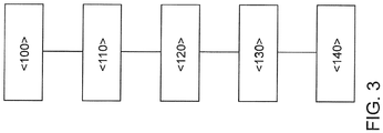
- FIG. 3 a flow chart for carrying out a method according to the invention for operating an internal combustion engine 10 is shown. It is to be solved by a combination of the connection of a selectively driven compressor 20 and an electric heating of an electric heating element 88 through a 48-volt electrical system of a motor vehicle of the conflict between minimum soot emissions and minimum nitrogen oxide emissions. At the same time, the increase in carbon dioxide emissions should be reduced.
- the optionally drivable electric compressor 20 in the air supply system 50 the filling of the combustion chambers 34 can be raised to such an extent, particularly in the dynamic operation of the internal combustion engine 10 and there just at positive load jumps that the particulate emissions can be significantly reduced in these operating conditions.
- the advantages of switching on the optionally drivable electric compressor 20 increase with increasing specific power of the internal combustion engine 10, since with a larger nozzle flow rate of the fuel injectors 94, which is necessary to achieve higher outputs, the level of particulate emissions also increases.
- a first method step ⁇ 100> the internal combustion engine 10 is started, wherein the electric heating element 88 of the electrically heatable catalyst 62 is heated from the start of the internal combustion engine 10 in a process step ⁇ 110> to heat the particle filter 46 as quickly as possible to a temperature from which a selective, catalytic reduction of nitrogen oxides is possible.
- a dynamic operation and / or the request of a load jump of the internal combustion engine 10 is detected by the control unit 90, wherein in a method step ⁇ 130> the selectively drivable electric compressor 20 is switched on.
- the filling of the combustion chambers 34 of the internal combustion engine 10 is improved in a process step ⁇ 140>, whereby the particulate emissions reduced can be.
- the connection of the selectively drivable electric compressor 20 leads to a pressure increase on the inlet side of the internal combustion engine 10, which leads to a reduction of the exhaust gas recirculation rate via the high-pressure exhaust gas recirculation 80 in a method step ⁇ 140> and an associated increase in the raw NOx emissions.
- the NOx storage catalytic converter 64 and / or the particle filter 46 with the SCR coating to reach its operating temperature as soon as possible after the cold start.
- the electrical heating of the electric heating element 88 is achieved by the electrical heating of the electric heating element 88.
- the electrical system 86 of the motor vehicle is a 48-volt electrical system.
- the combination of an optionally operable electric compressor 20 and an electrically heatable catalyst 62 thus proves to be particularly advantageous for the simultaneous achievement of low nitrogen oxide emissions and low particle emissions.
- the lower particulate emissions have the additional advantage that the particulate filter 46 must be regenerated less frequently, which in addition leads to a reduction of the additional consumption and the associated carbon dioxide emissions.
- FIG. 4 a temperature profile of the temperature in the particulate filter 46, in particular on the catalytically active coating of the particulate filter 46 is shown.
- the particle filter 46 is heated in a method (1) with electrically heated catalyst 62 already after about 70 seconds of continuous heating phase I by the electric heating element 88 to its light-off temperature with respect to the nitrogen oxide conversion, though the electric heating element 88 according to the invention is supplied with power from a 48-volt electrical system of a motor vehicle.
- the nitrogen oxides can be converted in an operating phase II into harmless molecular nitrogen, carbon dioxide and water vapor.
- the particle filter 46 without an upstream electric heating element 88 in a method (2) without electrically heating the exhaust gas stream at the same operating load only after about 360 seconds reaches its light-off temperature, from which nitrogen oxides efficiently into molecular nitrogen, Carbon dioxide and water vapor can be converted.
- the particulate filter 46 reaches its light-off temperature almost five minutes earlier, whereby the nitrogen oxide emissions can be significantly reduced, especially in a cold start phase.
Landscapes
- Engineering & Computer Science (AREA)
- Chemical & Material Sciences (AREA)
- Combustion & Propulsion (AREA)
- Mechanical Engineering (AREA)
- General Engineering & Computer Science (AREA)
- Chemical Kinetics & Catalysis (AREA)
- Health & Medical Sciences (AREA)
- Toxicology (AREA)
- Exhaust Gas After Treatment (AREA)
- Exhaust-Gas Circulating Devices (AREA)
Abstract
Description
- Die Erfindung betrifft eine Brennkraftmaschine mit einem Abgasnachbehandlungssystem und einem elektrisch antreibbaren Verdichter sowie ein Verfahren zum Betreiben einer solchen Brennkraftmaschine gemäß den Oberbegriffen der unabhängigen Patentansprüche.
- Die aktuelle und eine zukünftig immer schärfer werdende Abgasgesetzgebung stellen hohe Anforderungen an die motorischen Rohemissionen und die Abgasnachbehandlung von Verbrennungsmotoren. Dabei stellen die Forderungen nach einem weiter sinkenden Verbrauch und die weitere Verschärfung der Abgasnormen hinsichtlich der zulässigen StickoxidEmissionen und Rußpartikel eine Herausforderung für die Motorenentwickler dar. Der Ausstoß von Stickoxiden und Rußpartikeln ist gesetzlich begrenzt. In Zukunft sind weitere Verschärfungen der gesetzlichen Grenzwerte bezüglich dieser beiden Schadstoffe zu erwarten. Bei Ottomotoren erfolgt die Abgasreinigung in bekannter Weise über einen Drei-Wege-Katalysator, sowie dem Drei-Wege-Katalysator vor- und nachgeschaltete weitere Katalysatoren sowie einem Ottopartikelfilter. Bei Dieselmotoren finden aktuell Abgasnachbehandlungssysteme Verwendung, welche einen Oxidationskatalysator oder einen NOx-Speicherkatalysator, einen Katalysator zur selektiven katalytischen Reduktion von Stickoxiden (SCR-Katalysator) sowie einen Partikelfilter zur Abscheidung von Rußpartikeln und gegebenenfalls weitere Katalysatoren aufweisen. Durch die zunehmenden Anforderungen an die Abgasreinigung steigt die Anzahl der Abgasnachbehandlungskomponenten sowie deren Bauraumbedarf. Diese verursacht Package-, Gewichts- und Kostenprobleme. Zudem wird die Aktivierung der Abgasnachbehandlungskomponenten immer herausfordernder, wobei zum Aufheizen der Abgasnachbehandlungskomponenten zusätzliche Energie benötigt wird, welche die Kraftstoffeffizienz des Verbrennungsmotors reduziert und zu einem Mehrverbrauch führt. Es ist bekannt, dass durch ein Anheben der Abgasrückführungsrate die Stickoxid-Rohemissionen (NOx-Rohemissionen) gemindert werden können, jedoch gleichzeitig die Partikelemissionen ansteigen. Dieser Effekt, welcher auch als "Partikel-NOx-Tradeoff" bezeichnet wird, nimmt bei positiven Lastsprüngen mit der Dynamik der Laständerung noch zu, das heißt, die Partikelemissionen steigen zur Sicherstellung von niedrigen Stickoxidemissionen überproportional an.
- Brennkraftmaschinen werden mit Verdichtern betrieben, um die Leistung zu steigern und/oder den Wirkungsgrad der Brennkraftmaschine zu erhöhen. Insbesondere wahlweise antreibbare Verdichter werden genutzt, um die Betriebskennfelder von Brennkraftmaschinen zu optimieren. Dabei sind Abgasturbolader bekannt, bei denen der Verdichter wahlweise durch eine im Abgaskanal angeordnete Turbine und/oder durch einen elektrischen Zusatzantrieb angetrieben werden kann. Durch einen elektrisch antreibbaren Verdichter wird durch das veränderte Druckgefälle die Abgasrückführrate beeinflusst oder sogar komplett eingestellt, insbesondere wenn die Verdichter nicht mit einer Turbine im Abgasstrang gekoppelt sind.
- Die Beeinflussung einer Abgasrückführrate und die veränderte Durchflussmasse verursacht vom Verdichter haben einen negativen Effekt auf die Emissionen der Brennkraftmaschine. Insbesondere die Emissionen von Stickoxiden werden durch die eingeschränkten Abgasemissionen erhöht. Der erhöhte Massendurchfluss verursacht durch den Verdichter benötigt ein früheres Erreichen der Betriebstemperatur der Katalysatoren zur Abgasbehandlung, da sonst in Relation zu einem Betrieb ohne den wahlweise betriebenen Verdichter die Schademissionen des Abgases stark erhöht sind.
- Aus der
DE 10 2014 223 491 A1 ist ein Verbrennungsmotor mit einem Ansaugtrakt und einer Abgasanlage bekannt, welcher mittels eines Abgasturboladers und eines elektrischen Verdichters aufgeladen ist. In der Abgasanlage ist ein elektrisch beheizbarer NOx-Speicherkatalysator vorgesehen, welchem ein SCR-Katalysator nachgeschaltet ist.
Der Verbrennungsmotor weist ferner eine Gaszufuhreinrichtung auf, mit welcher eine von dem Verbrennungsmotor unabhängige Gasströmung durch die Abgasanlage erzeugt werden kann. Dabei wird der passive NOx-Speicherkatalysator auf eine Temperatur oberhalb dessen Desorptionstemperatur erhitzt und der SCR-Katalysator auf dessen Betriebstemperatur gehalten, wobei der passive NOx-Speicherkatalysator entladen wird. - Die
WO 2017 / 063 832 A1 offenbart ein Kraftfahrzeug, insbesondere ein Hybridfahrzeug, mit einem elektrischen 48-Volt-Bordnetz, wobei ein elektrisches Heizelement eines Katalysators und ein elektrischer Zusatzverdichter durch das 48-Volt-Bordnetz betrieben werden. - Der Erfindung liegt nun die Aufgabe zugrunde, die Abgasemissionen eines Verbrennungsmotors mit einem elektrisch antreibbaren Verdichter zu reduzieren und die Leistung des Verbrennungsmotors zu optimieren.
- Die Aufgabe wird durch eine Brennkraftmaschine mit einem wahlweise antreibbaren Verdichter auf einer Frischluftseite der Brennkraftmaschine und einem beheizbaren Katalysator auf einer Abgasseite der Brennkraftmaschine gelöst. Dabei sind die Brennkraftmaschine und der wahlweise antreibbare Verdichter mit einem Bordnetz eines Kraftfahrzeuges verbunden. Es ist vorgesehen, dass der Katalysator ein mit dem Bordnetz verbundenes elektrisches Heizelement umfasst und mit dem Heizelement das Substrat des Katalysators und/oder die Abgasseite stromaufwärts des Substrates des Katalysators beheizbar ist. So kann auf vorteilhafte Weise das Betriebskennfeld der Brennkraftmaschine mit dem Verdichter optimiert werden und mit dem Heizelement die Emission beim Betrieb des Verdichters optimiert werden. Dadurch können die Partikelrohemissionen gesenkt und gleichzeitig ein Anstieg der Stickoxidemissionen minimiert werden.
- Durch die in den abhängigen Ansprüchen genannten Merkmale sind vorteilhafte Weiterentwicklungen und nicht triviale Verbesserungen der im unabhängigen Anspruch angegebenen Brennkraftmaschine möglich.
- In bevorzugter Ausgestaltung der Erfindung ist vorgesehen, dass die Brennkraftmaschine mindestens eine Brennkammer umfasst, wobei die Brennkammer einlassseitig mit einem Luftversorgungssystem und auslassseitig mit einer Abgasanlage verbunden ist. Dabei ist die Brennkraftmaschine vorzugsweise als Hubkolbenmotor ausgeführt, in dessen Brennkammern ein Kraftstoff-Luft-Gemisch verbrannt wird.
- In einer vorteilhaften Weiterentwicklung der Brennkraftmaschine ist vorgesehen, dass in der Abgasanlage eine Turbine eines Abgasturboladers angeordnet ist, wobei die Turbine einen Verdichter in dem Luftversorgungssystem antreibt, wobei der wahlweise antreibbare Verdichter stromabwärts des Verdichters des Abgasturboladers angeordnet ist. Dadurch lässt sich neben den positiven Effekten des Abgasturboladers bezüglich einer Erhöhung der spezifischen Leistung der Brennkraftmaschine und des Gesamtwirkungsgrads ein zusätzlicher Verdichter zuschalten, welcher schneller als der Verdichter des Abgasturboladers auf einen dynamischen Lastsprung der Brennkraftmaschine reagiert und somit zu einer besseren Füllung der Brennkammern beiträgt.
- Besonders bevorzugt ist dabei, wenn der wahlweise antreibbare Verdichter in einem Bypass zum Ansaugkanal des Luftversorgungssystems angeordnet ist. Durch eine Anordnung des wahlweise antreibbaren Verdichters in einem Bypass kann dieser besonders einfach bedarfsgerecht zu- und abgeschaltet werden. Dabei liegt der wahlweise antreibbare Verdichter im abgeschalteten Betriebszustand nicht im Ansaugkanal, wodurch der Strömungswiderstand nicht ansteigt.
- In einer weiteren Verbesserung der Erfindung ist vorgesehen, dass an einer Verzweigung und/oder an einer Einmündung des Bypasses in den Ansaugkanal eine Steuerklappe angeordnet ist, mit welcher ein Luftstrom wahlweise durch den Ansaugkanal, durch den Bypass oder durch den Ansaugkanal und den Bypass geleitet werden kann. Durch eine solche Steuerklappe kann auf einfache Art und Weise die Frischluftversorgung über den Bypass und/oder den Ansaugkanal erfolgen, wodurch ein bedarfsgerechtes Zuschalten des wahlweise antreibbaren Verdichters erleichtert wird.
- In einer alternativen Ausführungsform der Erfindung ist vorgesehen, dass der wahlweise antreibbare Verdichter der Verdichter des Abgasturboladers ist, wobei der Verdichter zusätzlich oder alternativ zum Antrieb durch die Turbine des Abgasturboladers durch einen elektrischen Antriebsmotor antreibbar ist. Alternativ zu einem zusätzlichen Verdichter kann auch durch ein wahlweises Zuschalten eines elektrischen Antriebsmotors am Verdichter des Abgasturboladers das Ansprechverhalten in dynamischen Betriebszuständen der Brennkraftmaschine verbessert werden. Dabei kann der elektrische Antriebsmotor den Verdichter schneller aktivieren als die Turbine des Abgasturboladers, wodurch das Ansprechverhalten verbessert und das sogenannte "Turboloch" verkleinert wird. Dies führt nicht nur zu einer verbesserten Leistungscharakteristik der Brennkraftmaschine, sondern auch zu geringeren Partikelrohemissionen, da die Füllung verbessert wird und dem Kraftstoff in den Brennkammern mehr Sauerstoff für die Verbrennung zur Verfügung steht.
- Bevorzugt ist dabei, wenn der wahlweise antreibbare Verdichter eine Peakleistung von 2,5 KW - 6 KW aufweist. Durch eine solche Peakleistung kann sichergestellt werden, dass eine hinreichende Frischluftmenge durch den wahlweise antreibbaren Verdichter den Brennkammern des Verbrennungsmotors zugeführt wird, um effizient die Partikelrohemissionen zu minimieren.
- In einer bevorzugten Ausführungsform der Brennkraftmaschine ist vorgesehen, dass die Spannung des Bordnetzes 40 Volt - 56 Volt, insbesondere 48 Volt beträgt. Durch ein 48-Volt-Bordnetz kann auf vergleichsweise einfache Art und Weise hinreichend viel elektrische Leistung bereitgestellt werden, um sowohl das elektrische Heizelement in der Abgasanlage als auch gleichzeitig den elektrischen Antriebsmotor des wahlweise antreibbaren Verdichters mit Strom zu versorgen und die geforderten Leistungen darzustellen.
- So kann auf vorteilhafte Weise die Leistung des Heizelements des Katalysators und/oder der wahlweise angetriebene Verdichter für Brennkraftmaschinen in einer optimierten Größe gewählt werden, damit der Effekt dieser wesentlich für den Betrieb der Brennkraftmaschine ist.
- In einer vorteilhaften Ausführungsform der Erfindung ist vorgesehen, dass das Heizelement eine Heizleistung aufweist, welche zwischen 50 % und 100 % der Peakleistung des wahlweise antreibbaren Verdichters liegt.
- Bevorzugt ist dabei, dass der wahlweise antreibbare Verdichter so ausgelegt ist, damit diese Peakleistung für bis zu 100 ms oder 100 ms - 500 ms, insbesondere 100 ms - 400 ms, bevorzugt 100 ms - 300 ms, besonders bevorzugt 100 ms - 200 ms anforderbar ist.
- Durch die eingestellte Dauer der Peakleistung ist auf vorteilhafte Weise ein schneller Anlauf des wahlweise betreibbaren Verdichters gewährleistet, bis dieser auf eine gewünschte Betriebsleistung eingestellt werden kann. Somit kann ein Anstieg der Partikelemissionen durch eine mangelnde Frischluftzufuhr und eine unzureichende Umsetzung des in die Brennkammern eingespritzten Kraftstoffs verhindert werden.
- Besonders bevorzugt ist es, dass der wahlweise antreibbare Verdichter eine Leistungsdauer der Peakleistung von 200 ms - 500 ms aufweist.
- Erfindungsgemäß kann diese Betriebsleistung des Verdichters für bis zu 10 s abgerufen werden. Bevorzugt zwischen 1 und 3 s und noch bevorzugter 2 bis 3 s.
- Durch diese Betriebsleistung und/oder die Betriebsdauer kann vorteilhaft eine Leistungsoptimierung der Brennkraftmaschine erfolgen. Somit können sowohl die Rohemissionen als auch die Leistungscharakteristik der Brennkraftmaschine verbessert werden. Dies ist für den Fahrer insbesondere beim Beschleunigen aus niedrigen Drehzahlen zu spüren, wenn der Verdichter des Abgasturboladers durch geringe Drehzahlen der Turbine nur verzögert mit einem der Leistungsanforderung entsprechenden Leistungsaufbau beginnt.
- Die erfindungsgemäße Brennkraftmaschine kann einen Generator umfassen. Dieser Generator kann mit der Brennkraftmaschine wahlweise koppelbar sein. Darüber hinaus kann dieser Generator mit oder ohne eine Batterie als Stromquelle für den wahlweise antreibbaren Verdichter und/oder das Heizelement des Katalysators dienen. Darüber hinaus kann bei einer Nutzung des Generators eine Lastanhebung der Brennkraftmaschine erfolgen und die zusätzliche Arbeit der Brennkraftmaschine für den Generator genutzt werden. Bei dem Generator kann es sich bevorzugt um die Lichtmaschine der Brennkraftmaschine eines Fahrzeugs handeln. Das Fahrzeug kann bevorzugt ein Kraftfahrzeug für den Straßenverkehr sein.
- So kann auf vorteilhafte Weise der wahlweise antreibbare Verdichter und/oder das Heizelement des Katalysators mit Energie versorgt werden. Darüber hinaus kann so vorteilhaft durch die Lastanhebung der Brennkraftmaschine die Abgastemperatur weiter angehoben werden. Diese Bauteile und der erhöhte Energieeintrag in die Abgasanlage sorgen jeder für sich für einen verbesserten Betrieb der Abgasanlage und der Brennkraftmaschine und stehen hier aber in einer Synergie zueinander.
- In einer bevorzugten Ausführungsform ist die Brennkraftmaschine als selbstzündender Verbrennungsmotor nach dem Dieselprinzip, insbesondere als direkteinspritzender Dieselmotor, ausgeführt. Gerade Dieselmotoren sind aufgrund ihres im Vergleich zu Ottomotoren höheren thermischen Wirkungsgrad davon betroffen, dass ein Aufheizen der Katalysatoren durch den Abgasstrom vergleichsweise lange dauert, da das Abgas des Dieselmotors im Vergleich zu einem Ottomotor bei gleicher Leistungsanforderung kälter ist. Zudem wird der Dieselmotor betriebsbedingt mit einem Luftüberschuss betrieben, was die Abgasreinigung von Stickoxidemissionen erschwert. Um eine hocheffiziente Reduzierung dieser Stickoxidemissionen zu ermöglichen, ist eine Kombination aus einem NOx-Speicherkatalysator und einem nachgeschalteten SCR-Katalysator bekannt. Diese Katalysatoren benötigen jedoch eine Betriebstemperatur von mindestens 150°C (im Fall des NOx-Speicherkatalysators) beziehungsweise mindestens 200°C (im Falle des SCR-Katalysators), um eine effiziente Konvertierung von Stickoxiden zu ermöglichen. Dies wird durch das elektrische Heizelement in dem Substrat des Katalysators oder durch ein dem Substrat vorgeschaltetes elektrisches Heizelement erreicht.
- In einer bevorzugten Ausführungsform weist der Dieselmotor einen Hubraum von 0,35 dm3 bis 0,6 dm3 pro Brennraum auf. Dies entspricht bei einem Vierzylindermotor einem Hubraum von 1,4 dm3 bis 2,4 dm3 beziehungsweise bei einem Sechszylindermotor einem Hubraum von 2,1 dm3 bis 3,6 dm3. Brennräume mit dieser Größe haben sich bei Personenkraftwagen als besonders vorteilhaft bezüglich der zu erzielenden Leistung, dem Drehmoment und dem Verbrauch herausgestellt.
- In einer bevorzugten Ausführungsform weist der Dieselmotor drei bis acht Brennräume, bevorzugt vier bis sechs Brennräume auf. Um die Leistungsanforderung von Personenkraftfahrzeugen im Bereich von etwa 75 KW - 180 KW abzudecken, sind Vierzylindermotoren, mit einfacher oder mehrfacher Aufladung bevorzugt. Für Leistungen oberhalb von 150 KW kann die Verwendung eines Sechszylindermotors vorteilhaft sein, um die höhere Leistung und/oder eine höhere Anforderung an die Laufruhe der Brennkraftmaschine zu erfüllen.
- Die Brennkraftmaschine kann bevorzugt 40 kW pro Liter Hubraum bis 90 kW pro Liter Hubraum an Leistung liefern, wenn diese einen Turbolader umfasst, idealer Weise können 55 kW pro Liter Hubraum bis 80 kW pro Liter Hubraum vorgesehen sein. Die Brennkraftmaschine kann auch zwei Turbolader umfassen und dann eine Leistung von 75 kW pro Liter Hubraum bis 90 kW pro Liter Hubraum aufweisen.
- In einer vorteilhaften Ausführungsform der Brennkraftmaschine ist vorgesehen, dass in einer Abgasanlage der Brennkraftmaschine stromabwärts einer Turbine eines Abgasturboladers ein Oxidationskatalysator oder ein NOx-Speicherkatalysator, stromabwärts des Oxidationskatalysators oder des NOx-Speicherkatalysators ein Partikelfilter mit einer Beschichtung zur selektiven, katalytischen Reduktion von Stickoxiden (SCR-Beschichtung) und stromabwärts des Partikelfilters ein weiterer SCR-Katalysator angeordnet sind. Dadurch ist eine besonders effiziente Abgasnachbehandlung in Bezug auf Stickoxidemissionen und Rußpartikel möglich.
- Bevorzugt ist dabei eine Ausführungsform, bei der das elektrische Heizelement in den Oxidationskatalysator oder den NOx-Speicherkatalysator integriert ist oder einem dieser Katalysatoren unmittelbar vorgeschaltet ist. Um unmittelbar nach einem Kaltstart die Stickoxidemissionen zu senken, ist eine Zwischenspeicherung der Stickoxidemissionen in einem NOx-Speicherkatalysator sinnvoll, zumindest bis einer der SCR-Katalysatoren seine Betriebstemperatur erreicht hat. Durch ein zusätzliches elektrisches Beheizen des NOx-Speicherkatalysators wird dessen Betriebstemperatur von mehr als 150°C zeitnah nach einem Kaltstart der Brennkraftmaschine erreicht. Zudem kann das elektrische Heizelement genutzt werden, um den Abgasstrom der Brennkraftmaschine zu erwärmen, wodurch auch der Partikelfilter mit der SCR-Beschichtung zeitnah nach einem Kaltstart der Brennkraftmaschine seine Light-Off-Temperatur erreicht.
- Alternativ ist mit Vorteil vorgesehen, dass das elektrische Heizelement stromabwärts des Oxidationskatalysators oder des NOx-Speicherkatalysators und stromaufwärts des Partikelfilters angeordnet ist oder in den Partikelfilter integriert ist. Durch ein elektrisches Heizelement, welches dem Partikelfilter mit der SCR-Beschichtung zugeordnet ist, können Abwärmeverluste durch die Wand des Abgaskanals sowie eine zeitliche Verzögerung durch das Durchwärmen des Oxidationskatalysators oder des NOx-Speicherkatalysators vermieden werden. Dadurch erreicht die SCR-Beschichtung des Partikelfilters schneller ihre Light-Off-Temperatur.
- In einer bevorzugten Ausführungsform der Erfindung ist vorgesehen, dass die Brennkraftmaschine eine Hochdruck-Abgasrückführung aufweist, welche eine Auslassseite der Brennkammern mit einer Einlassseite der Brennkammern verbindet. Um auch bei niedrigen Abgastemperaturen und zeitnah nach einem Kaltstart der Brennkraftmaschine die Stickoxidemissionen zu minimieren, ist es sinnvoll, einen Teil des Abgasstroms über die Hochdruck-Abgasrückführung der Einlassseite der Brennkraftmaschine zuzuführen. Dadurch können die Stickoxidemissionen signifikant verringert werden.
- Besonders bevorzugt ist dabei, wenn in der Hochdruck-Abgasrückführung ein Abgasrückführungsventil und/oder ein Abgasrückführungskühler angeordnet sind. Durch einen Abgasrückführungskühler kann der positive Effekt der Abgasrückführung in Bezug auf die Stickoxidemissionen verstärkt werden. Dabei kann durch das Abgasrückführungsventil die Menge des zurückgeführten Abgases gesteuert werden, um eine emissionsoptimale Verbrennung in der Brennkammer der Brennkraftmaschine zu realisieren.
- In einer weiteren bevorzugten Ausgestaltung der Erfindung ist vorgesehen, dass stromabwärts des Partikelfilters eine Niederdruck-Abgasrückführung aus einem Abgaskanal der Abgasanlage abzweigt, welche stromaufwärts des Verdichters des Abgasturboladers in einen Ansaugkanal des Luftversorgungssystems einmündet. Durch eine Niederdruck-Abgasrückführung kann im Vergleich zu dem über die Hochdruck-Abgasrückführung zurückgeführten Abgas kälteres Abgas von der Abgasseite auf die Frischluftseite zurückgeführt werden, wodurch die Emissionen in einem Normalbetrieb der Brennkraftmaschine reduziert werden können.
- Erfindungsgemäß wird ein Verfahren zum Betreiben einer Brennkraftmaschine mit einem wahlweise angetriebenen Verdichter auf der Frischluftseite der Brennkraftmaschine und einem Katalysator auf einer Abgasseite der Brennkraftmaschine vorgeschlagen, wobei der wahlweise angetriebene Verdichter angetrieben wird und wobei der Katalysator ein elektrisches Heizelement umfasst, mit dem das Substrat des Katalysators und/oder die Abgasseite, insbesondere der Abgaskanal stromaufwärts des Substrates beheizt wird. Durch das gleichzeitige Beheizen des elektrischen Heizelements in der Abgasanlage und das Zuschalten des wahlweise angetriebenen Verdichters werden die Emissionen der Brennkraftmaschine reduziert.
- In einer Verbesserung des Verfahrens ist vorgesehen, das der wahlweise angetriebene Verdichter in einem dynamischen Betrieb der Brennkraftmaschine zugeschaltet wird, um die Partikelrohemissionen in der mindestens einen Brennkammer der Brennkraftmaschine zu senken. Durch das Zuschalten des wahlweise antreibbaren Verdichters wird die Füllung der Brennkammern in einem dynamischen Betrieb der Brennkraftmaschine, insbesondere bei positiven Lastsprüngen verbessert, wodurch der größeren Menge an eingespritztem Kraftstoff mehr Frischluft zur Umsetzung zur Verfügung steht. Dies reduziert die Partikelemissionen bei der Verbrennung, wodurch weniger Rußpartikel durch den Partikelfilter aus dem Abgasstrom der Brennkraftmaschine entfernt werden müssen. Dies verlängert die Regenerationsintervalle des Partikelfilters, wodurch der Kraftstoffverbrauch und die damit verbundenen Kohlenstoffdioxidemissionen verringert werden können.
- Die verschiedenen in dieser Anmeldung genannten Ausführungsformen der Erfindung sind, sofern im Einzelfall nicht anders ausgeführt, mit Vorteil miteinander kombinierbar.
- Die Erfindung wird nachfolgend in Ausführungsbeispielen anhand der zugehörigen Zeichnungen erläutert. Es zeigen:
- Figur 1
- ein erstes Ausführungsbeispiel für eine erfindungsgemäße Brennkraftmaschine mit einem elektrisch antreibbaren Verdichter;
- Figur 2
- ein weiteres Ausführungsbeispiel für eine erfindungsgemäße Brennkraftmaschine mit einem elektrisch antreibbaren Verdichter und einem Abgasnachbehandlungssystem;
- Figur 3
- ein Ablaufdiagramm zur Durchführung eines erfindungsgemäßen Verfahrens zum Betreiben einer Brennkraftmaschine; und
- Figur 4
- ein Temperaturverlauf beim Aufheizen eines Partikelfilters mit einer SCR-Beschichtung beim Betrieb einer erfindungsgemäßen Brennkraftmaschine.
-
Figur 1 zeigt ein erstes Ausführungsbeispiel einer erfindungsgemäßen Brennkraftmaschine 10. Die Brennkraftmaschine 10 umfasst auf der Frischgasseite an erster Stelle einen Luftfilter 12, einen Verdichter 14 eines Turboladers 16, darauf folgt ein Bypass 18, auf dem ein elektrisch angetriebener Verdichter 20 angeordnet ist. An einer Ausgangsseite des Bypasses 18 ist eine Klappe 22 angeordnet, diese Klappe 22 kann insbesondere eine Drei-Wege-Regelklappe sein. Nach dem Bypass 18 ist ein erster Drucksensor 24 angeordnet, dieser kann zur Regelung und/oder Messung der Frischluftmasse genutzt werden. Stromab des ersten Drucksensors 24 ist ein Ladeluftkühler 26 angeordnet. Stromab des Ladeluftkühlers 26 ist eine Einlassstelle 28 einer Abgasrückführung 30 angeordnet. Diese kann an einer zentralen Stelle stromauf eines Einlasskrümmers 32 in die Frischgasseite der Brennkraftmaschine 10 münden und/oder in mindestens einen spezifischen Einlasskanal des Einlasskrümmers 32 münden. Stromab des Einlasskrümmers 32 sind die Brennkammern 34 der Brennkraftmaschine 10 angeordnet. Diese münden in die Abgasseite der Brennkraftmaschine 10 und zwar aus jeder Brennkammer in den Abgaskrümmer 36 der Brennkraftmaschine 10. Stromab des Abgaskrümmers 36 ist auf der Abgasseite ein zweiter Drucksensor 38 angeordnet, dieser kann zur Bestimmung des Abgasgegendrucks genutzt werden und/oder zur Bemessung/Errechnung der Abgasrückführrate. Stromab des zweiten Drucksensors 38 ist die Turbine 40 eines Turboladers 16 angeordnet. Der Turbolader 16 kann insbesondere über eine variable Geometrie verfügen. Generell können die Turbolader 16 einer erfindungsgemäßen Brennkraftmaschine 10 über eine variable Geometrie verfügen. Stromab des Turboladers 16 sind in diesem Ausführungsbeispiel ein Dieseloxidationkatalysator 42 mit einem elektrischen Heizelement angeordnet, stromab dessen sich eine Dosiereinheit 44 für ein Reduktionsmittel (insbesondere wässrige Harnstofflösung) befindet. Stromab dessen folgt ein Partikelfilter 46 mit einer katalytischen Beschichtung zur Reduktion von Stickoxiden. Zwischen der Dosiereinheit 44 und einem Träger mit einer katalytischen Beschichtung zur Reduktion von Stickoxiden kann generell ein Mischer angeordnet sein, dieser ist hier in der Zeichnung allerdings nicht dargestellt. Stromab des Partikelfilters 46 mit einer katalytischen Beschichtung zur Reduktion von Stickoxiden ist hier ein weiterer Katalysator 48 angeordnet. Dieser kann ein Stickoxidspeicherkatalysator oder ein Katalysator zur selektiven Reduktion von Stickoxiden sein, es können aber auch beide Katalysatoren in einem Canning sein. - In
Figur 2 ist ein weiteres Ausführungsbeispiel einer erfindungsgemäßen Brennkraftmaschine 10 mit einem Luftversorgungssystem 50 und einer Abgasanlage 60 dargestellt. Die Brennkraftmaschine 10 ist als ein direkteinspritzender Dieselmotor ausgeführt und weist mehrere Brennkammern 34 auf. An den Brennkammern 34 ist jeweils ein Kraftstoffinjektor 94 zur Einspritzung eines Kraftstoffes in die jeweilige Brennkammer 34 angeordnet. Die Brennkraftmaschine ist einlassseitig mit einem Luftversorgungssystem 50 und auslassseitig mit einer Abgasanlage 60 verbunden. Die Brennkraftmaschine 10 umfasst ferner eine Hochdruck-Abgasrückführung 30, 80 mit einer Abgasrückführungsleitung 82 und einem Hochdruck-Abgasrückführungsventil 84, über welches ein Abgas der Brennkraftmaschine 10 von einem Abgaskrümmer 36 auf der Abgasseite zu einem Einlasskrümmer 32 auf der Frischluftseite zurückgeführt werden kann. An den Brennkammern 34 sind Einlassventile und Auslassventile angeordnet, mit welchen eine gasführende Verbindung von dem Luftversorgungssystem 50 zu den Brennkammern 34 oder von den Brennkammern 34 zur Abgasanlage 60 geöffnet oder verschlossen werden kann. - Das Luftversorgungssystem 50 umfasst einen Ansaugkanal 52, in welchem in Strömungsrichtung von Frischluft durch den Ansaugkanal 52 ein Luftfilter 12, stromabwärts des Luftfilters 12 ein Luftmassenmesser 58, insbesondere ein Heißfilmluftmassenmesser und stromabwärts des Luftmassenmessers 58 ein Verdichter 14 eines Abgasturboladers 16 angeordnet sind. Stromabwärts des Verdichters 14 zweigt an einer Verzweigung 54 ein Bypass 18 aus dem Ansaugkanal 52 ab, wobei in dem Bypass 18 ein elektrisch antreibbarer Verdichter 20 angeordnet ist.
- Der elektrisch antreibbare Verdichter 20 kann durch einen elektrischen Antriebsmotor 92 angetrieben werden, welcher aus einem Bordnetz 86 eines Kraftfahrzeuges, insbesondere einem 48-Volt-Bordnetz, mit Strom versorgt wird. Stromabwärts des elektrisch antreibbaren Verdichters 20 mündet der Bypass 18 wieder in den Ansaugkanal 52, wobei an einer Einmündung 56 des Bypasses 18 in den Ansaugkanal 52 eine Klappe 22, insbesondere eine Drei-Wege-Regelklappe, angeordnet ist, mit welcher ein Frischluftstrom wahlweise durch den Ansaugkanal 52, durch den Bypass 18 oder anteilig durch beide Kanäle 18, 52 geleitet werden kann.
- Stromabwärts der Einmündung 56 und stromaufwärts eines Einlasskrümmers 32 der Brennkraftmaschine 10 ist ein Ladeluftkühler 26 angeordnet, mit welchem die Frischluft vor Eintritt in die Brennkammern 34 abgekühlt wird, um die Füllung der Brennkammern 34 zu verbessern. Stromabwärts der Klappe 22 und stromaufwärts des Ladeluftkühlers 26 ist ein erster Drucksensor 24 vorgesehen, welcher zur Steuerung oder Regelung des Frischluftmassenstroms und/oder der Hochdruck-Abgasrückführung 30, 80 verwendet werden kann. Dazu ist stromabwärts des Ladeluftkühlers 26 eine Einlassstelle 28 vorgesehen, an welcher das über die Hochdruck-Abgasrückführung 30, 80 zurückgeführte Abgas der Frischluft aus dem Luftversorgungssystem 50 beigemischt wird.
- Der Luftmassenmesser 58 und der Luftfilter 12 können auch in einem gemeinsamen Gehäuse angeordnet sein, sodass der Luftfilter 12 und der Luftmassenmesser 58 eine Baugruppe ausbildet. Stromabwärts des Luftfilters 12 und stromaufwärts des Verdichters 14 des Abgasturboladers 16 ist eine Einmündung 78 vorgesehen, an welcher eine Abgasrückführungsleitung 72 einer Niederdruck-Abgasrückführung 70 in den Ansaugkanal 52 mündet.
- Die Abgasanlage 60 umfasst einen Abgaskanal 96, in welchem in Strömungsrichtung eines Abgases der Brennkraftmaschine 10 durch den ersten Abgaskanal 96 eine Turbine 40 des Abgasturboladers 16 angeordnet ist, welche den Verdichter 14 im Luftversorgungssystem 50 über eine Welle antreibt. Der Abgasturbolader 16 ist vorzugsweise als Abgasturbolader 16 mit variabler Turbinengeometrie ausgeführt. Dazu sind einem Turbinenrad der Turbine 40 verstellbare Leitschaufeln vorgeschaltet, über welche die Anströmung des Abgases auf die Schaufeln der Turbine 40 variiert werden kann. Stromabwärts der Turbine 40 sind mehrere Abgasnachbehandlungskomponenten 42, 46, 48, 62 vorgesehen.
- Dabei ist unmittelbar stromabwärts der Turbine 40 als erste Komponente der Abgasnachbehandlung ein Oxidationskatalysator 42 oder ein NOx-Speicherkatalysator 64 angeordnet. Stromabwärts des Oxidationskatalysators 42 oder des NOx-Speicherkatalysators 64 ist ein Partikelfilter 46 mit einer Beschichtung zur selektiven katalytischen Reduktion von Stickoxiden (SCR-Beschichtung) angeordnet. Der Oxidationskatalysator 42 oder der NOx-Speicherkatalyator 64 umfasst einen elektrisch beheizbaren Katalysator 62, mit welchem ein Abgasstrom der Brennkraftmaschine aufgeheizt werden kann. Alternativ kann dem Oxidationskatalysator 42 oder dem NOx-Speicherkatalysator 64 ein elektrisch beheizbarer Katalysator 62 vorgeschaltet sein, um den Abgasstrom der Brennkraftmaschine 10 vor Eintritt in den Oxidationskatalysator 42 oder den NOx-Speicherkatalysator 62 zu konditionieren. Stromabwärts des Partikelfilters 46 ist vorzugsweise in Unterbodenlage eines Kraftfahrzeuges ein zweiter SCR-Katalysator 48 im Abgaskanal 96 angeordnet. Der zweite SCR-Katalysator 96 kann einen Oxidationskatalysator, insbesondere einen Ammoniak-Sperrkatalysator aufweisen. Alternativ kann dem zweiten SCR-Katalysator 52 ein Ammoniak-Sperrkatalysator nachgeschaltet sein.
- Stromabwärts des Oxidationskatalysators 42 oder des NOx-Speicherkatalysators 64 und stromaufwärts des ersten SCR-Katalysators 48 ist eine Dosiereinheit 44 zur Eindosierung eines Reduktionsmittels, insbesondere von wässriger Harnstofflösung, in den Abgaskanal 96 vorgesehen. Stromabwärts des Partikelfilters 48 mit der SCR-Beschichtung zweigt eine Abgasrückführungsleitung 72 einer Niederdruck-Abgasrückführung 70 an einer Verzweigung 68 aus dem Abgaskanal 96 ab. Stromabwärts der Verzweigung 72 und stromaufwärts des zweiten SCR-Katalysators 52 ist eine Abgasklappe 66 angeordnet, mit welcher die Abgasrückführung über die Niederdruck-Abgasrückführung 70 gesteuert werden kann.
- Die Niederdruck-Abgasrückführung 70 umfasst neben der Abgasrückführungsleitung 72 einen Abgasrückführungskühler 74 und ein Abgasrückführungsventil 76, über welches die Abgasrückführung durch die Abgasrückführungsleitung 72 steuerbar ist. In dem Abgaskanal 96 kann eine Abgastemperatur durch einen Temperatursensor erfasst werden oder durch ein Steuergerät 90 berechnet werden, um die Niederdruck-Abgasrückführungen 70 zu aktivieren, sobald die Abgastemperatur TEG einen definierten Schwellenwert überschritten hat. An der Abgasrückführungsleitung 72 der Niederdruck-Abgasrückführung 70 kann ein weiterer Temperatursensor vorgesehen werden, um die Temperatur des zurückgeführten Abgases stromabwärts des Abgasrückführungskühlers 74 zu ermitteln. Dadurch kann vermieden werden, dass das zurückgeführte Abgas so stark gekühlt wird, dass der Taupunkt unterschritten wird und es zu einem Auskondensieren von Wassertropfen in der Abgasrückführungsleitung 72 kommt. Somit kann verhindert werden, dass Wasserdampf oder im Abgas enthaltene Gaskomponenten auskondensieren und in der Abgasrückführung 70 oder im Luftversorgungssystem 50 zu Beschädigungen oder Ablagerungen führen.
- Stromabwärts der Verzweigung 68 und stromaufwärts des Abgasrückführungskühlers 74 kann ein Filter vorgesehen werden, um den Eintrag von Partikeln in die Niederdruck-Abgasrückführung 70 zu minimieren. Die Abgasrückführungsleitung 72 mündet an einer Einmündung 78 in den Ansaugkanal 52 des Luftversorgungssystems 50.
- In der Abgasanlage 40 ist stromabwärts des Abgaskrümmers 36 und stromaufwärts der Turbine 40 des Abgasturboladers 16 ein zweiter Drucksensor 38 vorgesehen. Dieser kann zur Bestimmung des Abgasgegendrucks und/oder zur Bemessung/Errechnung der Abgasrückführrate genutzt werden.
- Dem Partikelfilter 46 ist ein Differenzdrucksensor 98 zugeordnet, mit welchem eine Druckdifferenz Δp über den Partikelfilter 46 ermittelt werden kann. Auf diese Weise kann der Beladungszustand des Partikelfilters 46 ermittelt und bei Überschreiten eines definierten Beladungsniveaus eine Regeneration des Partikelfilters 46 eingeleitet werden. Ferner ist in der Abgasanlage 60 ein Temperatursensor vorgesehen, um die Abgastemperatur TEG zu ermitteln. Stromabwärts der Dosiereinheit 44 und stromaufwärts des Partikelfilters 46 kann ein Abgasmischer 68 vorgesehen sein, um eine Durchmischung von Abgasstrom der Brennkraftmaschine 10 und des Reduktionsmittels vor Eintritt in den Partikelfilter 46 zu verbessern und die Länge der Mischstrecke zu verkürzen.
- Die Brennkraftmaschine 10 ist mit einem Steuergerät 90 verbunden, welches über nicht dargestellte Signalleitungen mit den Druck-Sensoren 24, 38, 98, den Temperatursensoren, den Kraftstoffinjektoren 94 der Brennkraftmaschine 10, der Dosiereinheit 44 und dem elektrisch antreibbaren Verdichter 20 sowie dem elektrischen Heizelement 88 des elektrisch beheizbaren Katalysators 62 verbunden ist.
- In
Figur 3 ist ein Ablaufdiagramm zur Durchführung eines erfindungsgemäßen Verfahrens zum Betreiben einer Brennkraftmaschine 10 dargestellt. Dabei soll durch eine Kombination des Zuschaltens eines wahlweise antreibbaren Verdichters 20 und eines elektrischen Beheizens eines elektrischen Heizelements 88 durch ein 48-Volt-Bordnetz eines Kraftfahrzeuges der Zielkonflikt zwischen minimalen Rußpartikelemissionen und minimalen Stickoxidemissionen gelöst werden. Gleichzeitig soll der Anstieg der Kohlenstoffdioxidemission gemindert werden. Mithilfe des wahlweise antreibbaren elektrischen Verdichters 20 im Luftversorgungssystem 50 kann insbesondere im dynamischen Betrieb der Brennkraftmaschine 10 und dort gerade bei positiven Lastsprüngen die Füllung der Brennkammern 34 so weit angehoben werden, dass die Partikelemissionen in diesen Betriebszuständen deutlich abgesenkt werden können. Die Vorteile eines Zuschaltens des wahlweise antreibbaren elektrischen Verdichters 20 nehmen mit steigender spezifischer Leistung der Brennkraftmaschine 10 zu, da mit größerem Düsendurchfluss der Kraftstoffinjektoren 94, welcher zum Erreichen höherer Leistungen notwendig ist, auch das Niveau der Partikelrohemissionen ansteigt. - In einem ersten Verfahrensschritt <100> wird die Brennkraftmaschine 10 gestartet, wobei das elektrische Heizelement 88 des elektrisch beheizbaren Katalysators 62 ab dem Start der Brennkraftmaschine 10 in einem Verfahrensschritt <110> beheizt wird, um den Partikelfilter 46 möglichst zeitnah auf eine Temperatur aufzuheizen, ab welcher eine selektive, katalytische Reduktion von Stickoxiden möglich ist. In einem Verfahrensschritt <120> wird durch das Steuergerät 90 ein dynamischer Betrieb und/oder die Anforderung eines Lastsprungs der Brennkraftmaschine 10 erkannt, wobei in einem Verfahrensschritt <130> der wahlweise antreibbare elektrische Verdichter 20 zugeschaltet wird. Durch den wahlweise antreibbaren elektrischen Verdichter 20 wird die Füllung der Brennkammern 34 der Brennkraftmaschine 10 in einem Verfahrensschritt <140> verbessert, wodurch die Partikelrohemissionen gemindert werden können. Das Zuschalten des wahlweise antreibbaren elektrischen Verdichters 20 führt zu einem Druckanstieg auf der Einlassseite der Brennkraftmaschine 10, was zu einer Reduzierung der Abgasrückführungsrate über die Hochdruck-Abgasrückführung 80 in einem Verfahrensschritt <140> und einem damit verbundenen Anstieg der NOx-Rohemissionen führt. Um diese NOx-Rohemissionen möglichst effektiv aus dem Abgasstrom der Brennkraftmaschine 10 zu entfernen, ist es notwendig, dass der NOx-Speicherkatalysator 64 und/oder der Partikelfilter 46 mit der SCR-Beschichtung möglichst schnell nach dem Kaltstart seine Betriebstemperatur erreichen. Dies wird durch das elektrische Beheizen des elektrischen Heizelements 88 erreicht. Um die notwendige elektrische Leistung für einen parallelen Betrieb des elektrisch angetriebenen Verdichters 20 und des elektrischen Heizelements 88 im elektrisch beheizbaren Katalysator 62 sicherzustellen, ist es vorteilhaft, wenn das Bordnetz 86 des Kraftfahrzeuges ein 48-Volt-Bordnetz ist.
- Die Kombination eines wahlweise betreibbaren elektrischen Verdichters 20 und eines elektrisch beheizbaren Katalysators 62 erweist sich somit als besonders vorteilhaft zum gleichzeitigen Erreichen von niedrigen Stickoxidemissionen und geringen Partikelemissionen. Die geringeren Partikelemissionen haben den zusätzlichen Vorteil, dass der Partikelfilter 46 seltener regeneriert werden muss, was zusätzlich zu einer Reduzierung des Mehrverbrauchs und der damit verbundenen Kohlenstoffdioxidemissionen führt.
- In
Figur 4 ist ein Temperaturverlauf der Temperatur im Partikelfilter 46, insbesondere an der katalytisch wirksamen Beschichtung des Partikelfilters 46 dargestellt. Dabei ist zu erkennen, dass der Partikelfilter 46 bei einem Verfahren (1) mit elektrisch beheiztem Katalysator 62 bereits nach einer etwa 70 Sekunden andauernden Heizphase I durch das elektrische Heizelement 88 auf seine Light-Off-Temperatur bezüglich der Stickoxid-Konvertierung aufgeheizt wird, wenn das elektrische Heizelement 88 erfindungsgemäß aus einem 48-Volt-Bordnetz eines Kraftfahrzeuges mit Strom versorgt wird. Dadurch sind im Vergleich zu 12-Volt-Bordnetzen deutlich größere Heizleistungen, insbesondere im Bereich von 2,5 kW - 6 kW möglich, um den Partikelfilter 46 auf seine Light-Off-Temperatur von etwa 200°C aufzuheizen. Dabei können die Stickoxide in einer Betriebsphase II in unschädlichen molekularen Stickstoff, Kohlenstoffdioxid und Wasserdampf konvertiert werden. - Ferner ist zu erkennen, dass der Partikelfilter 46 ohne ein vorgeschaltetes elektrisches Heizelement 88 in einem Verfahren (2) ohne elektrisches Beheizen des Abgasstroms bei gleicher Betriebslast erst nach etwa 360 Sekunden seine Light-Off-Temperatur erreicht, ab welcher Stickoxide effizient in molekularen Stickstoff, Kohlenstoffdioxid und Wasserdampf konvertiert werden können. Somit erreicht der Partikelfilter 46 fast fünf Minuten früher seine Light-Off-Temperatur, wodurch insbesondere in einer Kaltstartphase die Stickoxidemissionen deutlich reduziert werden können.
-
- 10
- Brennkraftmaschine
- 12
- Luftfilter
- 14
- Verdichter
- 16
- Abgasturbolader
- 18
- Bypass
- 20
- elektrisch angetriebener Verdichter
- 22
- Klappe
- 24
- erster Drucksensor
- 26
- Ladeluftkühler
- 28
- Einlassstelle
- 30
- Abgasrückführung
- 32
- Einlasskrümmer
- 34
- Brennkammer
- 36
- Abgaskrümmer
- 38
- zweiter Drucksensor
- 40
- Turbine
- 42
- Dieseloxidationskatalysator
- 44
- Dosiereinheit
- 46
- Partikelfilter
- 48
- SCR-Katalysator
- 50
- Luftversorgungssystem
- 52
- Ansaugkanal
- 54
- Verzweigung
- 56
- Einmündung
- 58
- Luftmassenmesser
- 60
- Abgasanlage
- 62
- elektrisch beheizbarer Katalysator
- 64
- NOx-Speicherkatalysator
- 66
- Abgasklappe
- 68
- Verzweigung
- 70
- Niederdruck-Abgasrückführung
- 72
- Abgasrückführungsleitung
- 74
- Abgasrückführungskühler
- 76
- Abgasrückführungsventil
- 78
- Einmündung
- 80
- Hochdruck-Abgasrückführung
- 82
- Abgasrückführungsleitung
- 84
- Abgasrückführungsventil
- 86
- Bordnetz
- 88
- elektrisches Heizelement
- 90
- Steuergerät
- 92
- elektrisches Antriebsmotor
- 94
- Kraftstoffinjektor
- 96
- Abgaskanal
- 98
- Differenzdrucksensor
- T
- Temperatur
- t
- Zeit
- I
- elektrische Heizphase
- II
- Betriebsphase
Claims (15)
- Brennkraftmaschine (10) mit einem wahlweise antreibbaren Verdichter (20) auf einer Frischluftseite der Brennkraftmaschine (10) und einem Katalysator (42, 46, 48, 62) auf einer Abgasseite der Brennkraftmaschine (10), wobei die Brennkraftmaschine (10) und der wahlweise antreibbare Verdichter (20) mit einem Bordnetz (86) verbunden sind, dadurch gekennzeichnet, dass der Katalysator (42, 46, 48, 62) ein mit dem Bordnetz (86) verbundenes Heizelement (88) umfasst und mit dem Heizelement (88) das Substrat des Katalysators (42, 46, 48, 62) und/oder die Abgasseite stromaufwärts des Substrates des Katalysators (42, 46, 48, 62) beheizbar ist.
- Brennkraftmaschine (10) nach Anspruch 1, dadurch gekennzeichnet, dass die Brennkraftmaschine (10) mindestens eine Brennkammer (34) umfasst, wobei die Brennkammer (34) einlassseitig mit einem Luftversorgungssystem (50) und auslassseitig mit einer Abgasanlage (60) verbunden ist.
- Brennkraftmaschine (10) nach Anspruch 2, dadurch gekennzeichnet, dass in der Abgasanlage (60) eine Turbine (40) eines Abgasturboladers (16) angeordnet ist, wobei die Turbine (40) einen Verdichter (14) in dem Luftversorgungssystem (50) antreibt, wobei der wahlweise antreibbare Verdichter (20) in einem Ansaugkanal (52) stromabwärts des Verdichters (14) des Abgasturboladers (16) angeordnet ist.
- Brennkraftmaschine (10) nach einem der Ansprüche 2 oder 3, dadurch gekennzeichnet, dass der wahlweise antreibbare Verdichter (20) in einem Bypass (18) zum Ansaugkanal (52) des Luftversorgungssystems (50) angeordnet ist.
- Brennkraftmaschine (10) nach Anspruch 2, dadurch gekennzeichnet, dass der wahlweise antreibbare Verdichter (20) der Verdichter (14) des Abgasturboladers (16) ist, wobei der Verdichter (14, 20) zusätzlich oder alternativ zum Antrieb durch die Turbine (40) des Abgasturboladers (16) in der Abgasanlage (60) durch einen elektrischen Antriebsmotor (92) antreibbar ist.
- Brennkraftmaschine (10) nach einem der Ansprüche 1 bis 5, dadurch gekennzeichnet, dass der wahlweise antreibbare Verdichter (20) eine Peakleistung von 2,5 - 6 kW aufweist.
- Brennkraftmaschine (10) nach einem der Ansprüche 1 bis 6, dadurch gekennzeichnet, dass die Spannung des Bordnetzes 40 - 56 Volt beträgt.
- Brennkraftmaschine (10) nach einem der Ansprüche 1 bis 7, dadurch gekennzeichnet, dass das Heizelement (88) eine Heizleistung aufweist, welche zwischen 50 % und 100 % der Peakleistung des wahlweise antreibbaren Verdichters (20) liegt.
- Brennkraftmaschine (10) nach einem der Ansprüche 1 bis 8, dadurch gekennzeichnet, dass die Brennkraftmaschine als selbstzündender Verbrennungsmotor nach dem Dieselprinzip ausgeführt ist.
- Brennkraftmaschine (10) nach einem der Ansprüche 1 bis 9, dadurch gekennzeichnet, dass in einer Abgasanlage (60) der Brennkraftmaschine (10) stromabwärts einer Turbine (40) eines Abgasturboladers (16) ein Oxidationskatalysator (42) oder ein NOx-Speicherkatalysator (64), stromabwärts des Oxidationskatalysators (42) oder des NOx-Speicherkatalysators (64) ein Partikelfilter (46) mit einer Beschichtung zur selektiven, katalytischen Reduktion von Stickoxiden, und stromabwärts des Partikelfilters (46) ein weiterer SCR-Katalysator (48) angeordnet sind.
- Brennkraftmaschine (10) nach Anspruch 10, dadurch gekennzeichnet, dass das Heizelement (88) in den Oxidationskatalysator (42) oder den NOx-Speicherkatalysator (64) integriert oder einem dieser Katalysatoren (42, 64) unmittelbar vorgeschaltet ist.
- Brennkraftmaschine (10) nach Anspruch 10, dadurch gekennzeichnet, dass das Heizelement (88) stromabwärts des Oxidationskatalysators (42) oder des NOx-Speicherkatalysators (64) und stromaufwärts des Partikelfilters (46) angeordnet ist oder in den Partikelfilter (46) integriert ist.
- Brennkraftmaschine (10) nach einem der Ansprüche 10 bis 12, dadurch gekennzeichnet, dass stromabwärts des Partikelfilters (46) eine Niederdruck-Abgasrückführung (70) aus einem Abgaskanal der Abgasanlage (60) abzweigt, welche stromaufwärts des Verdichters (14) des Abgasturboladers (16) in einen Ansaugkanal (52) des Luftversorgungssystems (50) einmündet.
- Verfahren zum Betreiben einer Brennkraftmaschine (10) mit einem wahlweise angetriebenen Verdichter (20) auf einer Frischluftseite der Brennkraftmaschine (10) und einem Katalysator (42, 46, 48, 62) auf einer Abgasseite der Brennkraftmaschine (10), wobei der wahlweise angetriebene Verdichter angetrieben wird, dadurch gekennzeichnet, dass der Katalysator ein Heizelement (88) umfasst, mit dem das Substrat des Katalysators (42, 46, 48, 62) und/oder die Abgasseite stromaufwärts des Substrates beheizt wird.
- Verfahren zum Betreiben einer Brennkraftmaschine (10) nach Anspruch 14, dadurch gekennzeichnet, dass der wahlweise angetriebene Verdichter (20) in einem dynamischen Betrieb der Brennkraftmaschine (10) zugeschaltet wird, um die Partikelrohemissionen in der mindestens einen Brennkammer (34) der Brennkraftmaschine (10) zu senken.
Applications Claiming Priority (2)
| Application Number | Priority Date | Filing Date | Title |
|---|---|---|---|
| DE102018206245 | 2018-04-24 | ||
| DE102019106773.1A DE102019106773A1 (de) | 2018-04-24 | 2019-03-18 | Brennkraftmaschine und Verfahren zum Betreiben einer Brennkraftmaschine |
Publications (2)
| Publication Number | Publication Date |
|---|---|
| EP3561262A1 true EP3561262A1 (de) | 2019-10-30 |
| EP3561262B1 EP3561262B1 (de) | 2021-03-31 |
Family
ID=66092143
Family Applications (1)
| Application Number | Title | Priority Date | Filing Date |
|---|---|---|---|
| EP19167251.8A Active EP3561262B1 (de) | 2018-04-24 | 2019-04-04 | Brennkraftmaschine und verfahren zum betreiben einer brennkraftmaschine |
Country Status (1)
| Country | Link |
|---|---|
| EP (1) | EP3561262B1 (de) |
Citations (4)
| Publication number | Priority date | Publication date | Assignee | Title |
|---|---|---|---|---|
| DE102014223491A1 (de) | 2014-11-18 | 2016-05-19 | Bayerische Motoren Werke Aktiengesellschaft | Abgasbehandlungsvorrichtung und Verfahren zur Abgasbehandlung |
| WO2017063832A1 (de) | 2015-10-12 | 2017-04-20 | Continental Automotive Gmbh | Fahrzeugbordnetz |
| WO2017100097A1 (en) * | 2015-12-07 | 2017-06-15 | Achates Power, Inc. | Air handling in a heavy-duty opposed-piston engine |
| EP3406878A1 (de) * | 2016-03-07 | 2018-11-28 | Mitsubishi Heavy Industries Engine & Turbocharger, Ltd. | Aufladesystem, steuerungsvorrichtung für ein aufladesystem, steuerungsverfahren für ein aufladesystem und programm |
-
2019
- 2019-04-04 EP EP19167251.8A patent/EP3561262B1/de active Active
Patent Citations (4)
| Publication number | Priority date | Publication date | Assignee | Title |
|---|---|---|---|---|
| DE102014223491A1 (de) | 2014-11-18 | 2016-05-19 | Bayerische Motoren Werke Aktiengesellschaft | Abgasbehandlungsvorrichtung und Verfahren zur Abgasbehandlung |
| WO2017063832A1 (de) | 2015-10-12 | 2017-04-20 | Continental Automotive Gmbh | Fahrzeugbordnetz |
| WO2017100097A1 (en) * | 2015-12-07 | 2017-06-15 | Achates Power, Inc. | Air handling in a heavy-duty opposed-piston engine |
| EP3406878A1 (de) * | 2016-03-07 | 2018-11-28 | Mitsubishi Heavy Industries Engine & Turbocharger, Ltd. | Aufladesystem, steuerungsvorrichtung für ein aufladesystem, steuerungsverfahren für ein aufladesystem und programm |
Also Published As
| Publication number | Publication date |
|---|---|
| EP3561262B1 (de) | 2021-03-31 |
Similar Documents
| Publication | Publication Date | Title |
|---|---|---|
| EP3660287B1 (de) | Abgasnachbehandlungssystem sowie verfahren zur abgasnachbehandlung eines verbrennungsmotors | |
| DE102018101929A1 (de) | Vorrichtung und Verfahren zur Abgasnachbehandlung eines Verbrennungsmotors | |
| WO2017037093A1 (de) | Verfahren sowie vorrichtung zur abgasnachbehandlung einer brennkraftmaschine | |
| DE102018104151A1 (de) | Abgasnachbehandlungssystem und Verfahren zur Abgasnachbehandlung eines Verbrennungsmotors | |
| DE102016212249A1 (de) | Zweistufig aufladbare direkteinspritzende Brennkraftmaschine mit Abgasnachbehandlung und Verfahren zum Betreiben einer derartigen Brennkraftmaschine | |
| EP4026994B1 (de) | Abgasnachbehandlungssystem sowie verfahren zur abgasnachbehandlung eines verbrennungsmotors | |
| DE102018126621A1 (de) | Abgasnachbehandlungssystem sowie Verfahren zur Abgasnachbehandlung eines Verbrennungsmotors | |
| DE102020100529A1 (de) | Verbrennungsmotor sowie Verfahren zum Aufheizen einer Abgasanlage eines solchen Verbrennungsmotors | |
| DE102020100539A1 (de) | Verfahren zum Betreiben eines Kraftfahrzeugs mit einem Diesel-Hybrid-Antrieb sowie Diesel-Hybrid-Antrieb | |
| DE102020103565B4 (de) | Verfahren zur Abgasnachbehandlung eines Verbrennungsmotors sowie Verbrennungsmotor | |
| DE102018104275A1 (de) | Abgasnachbehandlungssystem sowie Verfahren zur Abgasnachbehandlung eines Verbrennungsmotors | |
| EP1722080B1 (de) | Brennkraftmaschine und Verfahren zum Betreiben dieser | |
| EP3441587A1 (de) | Verfahren zum betreiben eines verbrennungsmotors | |
| DE102019106773A1 (de) | Brennkraftmaschine und Verfahren zum Betreiben einer Brennkraftmaschine | |
| EP4102036B1 (de) | Verfahren zur aufheizung eines elektrisch beheizbaren katalysators im leerlauf | |
| EP3561262B1 (de) | Brennkraftmaschine und verfahren zum betreiben einer brennkraftmaschine | |
| EP4036386B1 (de) | Verbrennungskraftmaschine für ein kraftfahrzeug, insbesondere für einen kraftwagen, sowie kraftfahrzeug, insbesondere kraftwagen | |
| DE102019123453A1 (de) | Abgasnachbehandlungssystem und Verfahren zum Temperaturmanagement eines SCR-Katalysators in der Abgasanlage eines Verbrennungsmotors | |
| DE102018127643A1 (de) | Abgasnachbehandlungssystem und Verfahren zur Abgasnachbehandlung eines Verbrennungsmotors | |
| DE102017123492A1 (de) | Abgasnachbehandlungssystem und Verfahren zur Abgasnachbehandlung eines Verbrennungsmotors | |
| DE102019107009A1 (de) | Verfahren zum Betreiben einer Brennkraftmaschine sowie eine Brennkraftmaschine | |
| DE102020117724A1 (de) | Abgasnachbehandlungssystem sowie Verfahren zur Abgasnachbehandlung eines Verbrennungsmotors | |
| EP4074946B1 (de) | Verfahren zur abgasnachbehandlung eines dieselmotors und dieselmotor | |
| DE102018108685A1 (de) | Dieselmotor und Verfahren zum Betreiben eines Dieselmotors | |
| DE102021115663A1 (de) | Abgasnachbehandlungssystem und Verfahren zur Abgasnachbehandlung eines Verbrennungsmotors |
Legal Events
| Date | Code | Title | Description |
|---|---|---|---|
| PUAI | Public reference made under article 153(3) epc to a published international application that has entered the european phase |
Free format text: ORIGINAL CODE: 0009012 |
|
| STAA | Information on the status of an ep patent application or granted ep patent |
Free format text: STATUS: THE APPLICATION HAS BEEN PUBLISHED |
|
| AK | Designated contracting states |
Kind code of ref document: A1 Designated state(s): AL AT BE BG CH CY CZ DE DK EE ES FI FR GB GR HR HU IE IS IT LI LT LU LV MC MK MT NL NO PL PT RO RS SE SI SK SM TR |
|
| AX | Request for extension of the european patent |
Extension state: BA ME |
|
| STAA | Information on the status of an ep patent application or granted ep patent |
Free format text: STATUS: REQUEST FOR EXAMINATION WAS MADE |
|
| 17P | Request for examination filed |
Effective date: 20200430 |
|
| RBV | Designated contracting states (corrected) |
Designated state(s): AL AT BE BG CH CY CZ DE DK EE ES FI FR GB GR HR HU IE IS IT LI LT LU LV MC MK MT NL NO PL PT RO RS SE SI SK SM TR |
|
| GRAP | Despatch of communication of intention to grant a patent |
Free format text: ORIGINAL CODE: EPIDOSNIGR1 |
|
| STAA | Information on the status of an ep patent application or granted ep patent |
Free format text: STATUS: GRANT OF PATENT IS INTENDED |
|
| INTG | Intention to grant announced |
Effective date: 20201111 |
|
| GRAS | Grant fee paid |
Free format text: ORIGINAL CODE: EPIDOSNIGR3 |
|
| GRAA | (expected) grant |
Free format text: ORIGINAL CODE: 0009210 |
|
| STAA | Information on the status of an ep patent application or granted ep patent |
Free format text: STATUS: THE PATENT HAS BEEN GRANTED |
|
| AK | Designated contracting states |
Kind code of ref document: B1 Designated state(s): AL AT BE BG CH CY CZ DE DK EE ES FI FR GB GR HR HU IE IS IT LI LT LU LV MC MK MT NL NO PL PT RO RS SE SI SK SM TR |
|
| REG | Reference to a national code |
Ref country code: GB Ref legal event code: FG4D Free format text: NOT ENGLISH Ref country code: CH Ref legal event code: EP |
|
| REG | Reference to a national code |
Ref country code: DE Ref legal event code: R096 Ref document number: 502019001079 Country of ref document: DE Ref country code: AT Ref legal event code: REF Ref document number: 1377182 Country of ref document: AT Kind code of ref document: T Effective date: 20210415 |
|
| REG | Reference to a national code |
Ref country code: IE Ref legal event code: FG4D Free format text: LANGUAGE OF EP DOCUMENT: GERMAN |
|
| REG | Reference to a national code |
Ref country code: LT Ref legal event code: MG9D |
|
| PG25 | Lapsed in a contracting state [announced via postgrant information from national office to epo] |
Ref country code: BG Free format text: LAPSE BECAUSE OF FAILURE TO SUBMIT A TRANSLATION OF THE DESCRIPTION OR TO PAY THE FEE WITHIN THE PRESCRIBED TIME-LIMIT Effective date: 20210630 Ref country code: HR Free format text: LAPSE BECAUSE OF FAILURE TO SUBMIT A TRANSLATION OF THE DESCRIPTION OR TO PAY THE FEE WITHIN THE PRESCRIBED TIME-LIMIT Effective date: 20210331 Ref country code: FI Free format text: LAPSE BECAUSE OF FAILURE TO SUBMIT A TRANSLATION OF THE DESCRIPTION OR TO PAY THE FEE WITHIN THE PRESCRIBED TIME-LIMIT Effective date: 20210331 Ref country code: NO Free format text: LAPSE BECAUSE OF FAILURE TO SUBMIT A TRANSLATION OF THE DESCRIPTION OR TO PAY THE FEE WITHIN THE PRESCRIBED TIME-LIMIT Effective date: 20210630 |
|
| PG25 | Lapsed in a contracting state [announced via postgrant information from national office to epo] |
Ref country code: RS Free format text: LAPSE BECAUSE OF FAILURE TO SUBMIT A TRANSLATION OF THE DESCRIPTION OR TO PAY THE FEE WITHIN THE PRESCRIBED TIME-LIMIT Effective date: 20210331 Ref country code: LV Free format text: LAPSE BECAUSE OF FAILURE TO SUBMIT A TRANSLATION OF THE DESCRIPTION OR TO PAY THE FEE WITHIN THE PRESCRIBED TIME-LIMIT Effective date: 20210331 Ref country code: SE Free format text: LAPSE BECAUSE OF FAILURE TO SUBMIT A TRANSLATION OF THE DESCRIPTION OR TO PAY THE FEE WITHIN THE PRESCRIBED TIME-LIMIT Effective date: 20210331 |
|
| REG | Reference to a national code |
Ref country code: NL Ref legal event code: MP Effective date: 20210331 |
|
| PG25 | Lapsed in a contracting state [announced via postgrant information from national office to epo] |
Ref country code: SM Free format text: LAPSE BECAUSE OF FAILURE TO SUBMIT A TRANSLATION OF THE DESCRIPTION OR TO PAY THE FEE WITHIN THE PRESCRIBED TIME-LIMIT Effective date: 20210331 Ref country code: NL Free format text: LAPSE BECAUSE OF FAILURE TO SUBMIT A TRANSLATION OF THE DESCRIPTION OR TO PAY THE FEE WITHIN THE PRESCRIBED TIME-LIMIT Effective date: 20210331 Ref country code: EE Free format text: LAPSE BECAUSE OF FAILURE TO SUBMIT A TRANSLATION OF THE DESCRIPTION OR TO PAY THE FEE WITHIN THE PRESCRIBED TIME-LIMIT Effective date: 20210331 Ref country code: CZ Free format text: LAPSE BECAUSE OF FAILURE TO SUBMIT A TRANSLATION OF THE DESCRIPTION OR TO PAY THE FEE WITHIN THE PRESCRIBED TIME-LIMIT Effective date: 20210331 Ref country code: LT Free format text: LAPSE BECAUSE OF FAILURE TO SUBMIT A TRANSLATION OF THE DESCRIPTION OR TO PAY THE FEE WITHIN THE PRESCRIBED TIME-LIMIT Effective date: 20210331 |
|
| PG25 | Lapsed in a contracting state [announced via postgrant information from national office to epo] |
Ref country code: SK Free format text: LAPSE BECAUSE OF FAILURE TO SUBMIT A TRANSLATION OF THE DESCRIPTION OR TO PAY THE FEE WITHIN THE PRESCRIBED TIME-LIMIT Effective date: 20210331 Ref country code: PT Free format text: LAPSE BECAUSE OF FAILURE TO SUBMIT A TRANSLATION OF THE DESCRIPTION OR TO PAY THE FEE WITHIN THE PRESCRIBED TIME-LIMIT Effective date: 20210802 Ref country code: RO Free format text: LAPSE BECAUSE OF FAILURE TO SUBMIT A TRANSLATION OF THE DESCRIPTION OR TO PAY THE FEE WITHIN THE PRESCRIBED TIME-LIMIT Effective date: 20210331 Ref country code: PL Free format text: LAPSE BECAUSE OF FAILURE TO SUBMIT A TRANSLATION OF THE DESCRIPTION OR TO PAY THE FEE WITHIN THE PRESCRIBED TIME-LIMIT Effective date: 20210331 Ref country code: IS Free format text: LAPSE BECAUSE OF FAILURE TO SUBMIT A TRANSLATION OF THE DESCRIPTION OR TO PAY THE FEE WITHIN THE PRESCRIBED TIME-LIMIT Effective date: 20210731 |
|
| PG25 | Lapsed in a contracting state [announced via postgrant information from national office to epo] |
Ref country code: LU Free format text: LAPSE BECAUSE OF NON-PAYMENT OF DUE FEES Effective date: 20210404 |
|
| REG | Reference to a national code |
Ref country code: DE Ref legal event code: R097 Ref document number: 502019001079 Country of ref document: DE |
|
| REG | Reference to a national code |
Ref country code: BE Ref legal event code: MM Effective date: 20210430 |
|
| PG25 | Lapsed in a contracting state [announced via postgrant information from national office to epo] |
Ref country code: ES Free format text: LAPSE BECAUSE OF FAILURE TO SUBMIT A TRANSLATION OF THE DESCRIPTION OR TO PAY THE FEE WITHIN THE PRESCRIBED TIME-LIMIT Effective date: 20210331 Ref country code: DK Free format text: LAPSE BECAUSE OF FAILURE TO SUBMIT A TRANSLATION OF THE DESCRIPTION OR TO PAY THE FEE WITHIN THE PRESCRIBED TIME-LIMIT Effective date: 20210331 Ref country code: AL Free format text: LAPSE BECAUSE OF FAILURE TO SUBMIT A TRANSLATION OF THE DESCRIPTION OR TO PAY THE FEE WITHIN THE PRESCRIBED TIME-LIMIT Effective date: 20210331 Ref country code: MC Free format text: LAPSE BECAUSE OF FAILURE TO SUBMIT A TRANSLATION OF THE DESCRIPTION OR TO PAY THE FEE WITHIN THE PRESCRIBED TIME-LIMIT Effective date: 20210331 |
|
| PLBE | No opposition filed within time limit |
Free format text: ORIGINAL CODE: 0009261 |
|
| STAA | Information on the status of an ep patent application or granted ep patent |
Free format text: STATUS: NO OPPOSITION FILED WITHIN TIME LIMIT |
|
| 26N | No opposition filed |
Effective date: 20220104 |
|
| REG | Reference to a national code |
Ref country code: DE Ref legal event code: R082 Ref document number: 502019001079 Country of ref document: DE |
|
| PG25 | Lapsed in a contracting state [announced via postgrant information from national office to epo] |
Ref country code: IE Free format text: LAPSE BECAUSE OF NON-PAYMENT OF DUE FEES Effective date: 20210404 |
|
| PG25 | Lapsed in a contracting state [announced via postgrant information from national office to epo] |
Ref country code: IS Free format text: LAPSE BECAUSE OF FAILURE TO SUBMIT A TRANSLATION OF THE DESCRIPTION OR TO PAY THE FEE WITHIN THE PRESCRIBED TIME-LIMIT Effective date: 20210731 |
|
| PG25 | Lapsed in a contracting state [announced via postgrant information from national office to epo] |
Ref country code: IT Free format text: LAPSE BECAUSE OF FAILURE TO SUBMIT A TRANSLATION OF THE DESCRIPTION OR TO PAY THE FEE WITHIN THE PRESCRIBED TIME-LIMIT Effective date: 20210331 Ref country code: BE Free format text: LAPSE BECAUSE OF NON-PAYMENT OF DUE FEES Effective date: 20210430 |
|
| REG | Reference to a national code |
Ref country code: CH Ref legal event code: PL |
|
| PG25 | Lapsed in a contracting state [announced via postgrant information from national office to epo] |
Ref country code: LI Free format text: LAPSE BECAUSE OF NON-PAYMENT OF DUE FEES Effective date: 20220430 Ref country code: CH Free format text: LAPSE BECAUSE OF NON-PAYMENT OF DUE FEES Effective date: 20220430 |
|
| P01 | Opt-out of the competence of the unified patent court (upc) registered |
Effective date: 20230523 |
|
| PG25 | Lapsed in a contracting state [announced via postgrant information from national office to epo] |
Ref country code: CY Free format text: LAPSE BECAUSE OF FAILURE TO SUBMIT A TRANSLATION OF THE DESCRIPTION OR TO PAY THE FEE WITHIN THE PRESCRIBED TIME-LIMIT Effective date: 20210331 |
|
| PG25 | Lapsed in a contracting state [announced via postgrant information from national office to epo] |
Ref country code: HU Free format text: LAPSE BECAUSE OF FAILURE TO SUBMIT A TRANSLATION OF THE DESCRIPTION OR TO PAY THE FEE WITHIN THE PRESCRIBED TIME-LIMIT; INVALID AB INITIO Effective date: 20190404 Ref country code: GR Free format text: LAPSE BECAUSE OF FAILURE TO SUBMIT A TRANSLATION OF THE DESCRIPTION OR TO PAY THE FEE WITHIN THE PRESCRIBED TIME-LIMIT Effective date: 20210331 |
|
| PG25 | Lapsed in a contracting state [announced via postgrant information from national office to epo] |
Ref country code: MK Free format text: LAPSE BECAUSE OF FAILURE TO SUBMIT A TRANSLATION OF THE DESCRIPTION OR TO PAY THE FEE WITHIN THE PRESCRIBED TIME-LIMIT Effective date: 20210331 |
|
| PG25 | Lapsed in a contracting state [announced via postgrant information from national office to epo] |
Ref country code: TR Free format text: LAPSE BECAUSE OF FAILURE TO SUBMIT A TRANSLATION OF THE DESCRIPTION OR TO PAY THE FEE WITHIN THE PRESCRIBED TIME-LIMIT Effective date: 20210331 |
|
| PGFP | Annual fee paid to national office [announced via postgrant information from national office to epo] |
Ref country code: GB Payment date: 20240423 Year of fee payment: 6 |
|
| PGFP | Annual fee paid to national office [announced via postgrant information from national office to epo] |
Ref country code: DE Payment date: 20240430 Year of fee payment: 6 |
|
| PGFP | Annual fee paid to national office [announced via postgrant information from national office to epo] |
Ref country code: FR Payment date: 20240430 Year of fee payment: 6 |
|
| PG25 | Lapsed in a contracting state [announced via postgrant information from national office to epo] |
Ref country code: MT Free format text: LAPSE BECAUSE OF FAILURE TO SUBMIT A TRANSLATION OF THE DESCRIPTION OR TO PAY THE FEE WITHIN THE PRESCRIBED TIME-LIMIT Effective date: 20210331 |
|
| REG | Reference to a national code |
Ref country code: AT Ref legal event code: MM01 Ref document number: 1377182 Country of ref document: AT Kind code of ref document: T Effective date: 20240404 |
|
| PG25 | Lapsed in a contracting state [announced via postgrant information from national office to epo] |
Ref country code: AT Free format text: LAPSE BECAUSE OF NON-PAYMENT OF DUE FEES Effective date: 20240404 |
|
| REG | Reference to a national code |
Ref country code: DE Ref legal event code: R119 Ref document number: 502019001079 Country of ref document: DE |
|
| GBPC | Gb: european patent ceased through non-payment of renewal fee |
Effective date: 20250404 |
|
| PG25 | Lapsed in a contracting state [announced via postgrant information from national office to epo] |
Ref country code: DE Free format text: LAPSE BECAUSE OF NON-PAYMENT OF DUE FEES Effective date: 20251104 |
|
| PG25 | Lapsed in a contracting state [announced via postgrant information from national office to epo] |
Ref country code: GB Free format text: LAPSE BECAUSE OF NON-PAYMENT OF DUE FEES Effective date: 20250404 |
|
| PG25 | Lapsed in a contracting state [announced via postgrant information from national office to epo] |
Ref country code: FR Free format text: LAPSE BECAUSE OF NON-PAYMENT OF DUE FEES Effective date: 20250430 |
|
| PGFP | Annual fee paid to national office [announced via postgrant information from national office to epo] |
Ref country code: AT Payment date: 20260410 Year of fee payment: 5 |