EP3561212A1 - Automatic switching device and refrigeration device - Google Patents
Automatic switching device and refrigeration device Download PDFInfo
- Publication number
- EP3561212A1 EP3561212A1 EP17884318.1A EP17884318A EP3561212A1 EP 3561212 A1 EP3561212 A1 EP 3561212A1 EP 17884318 A EP17884318 A EP 17884318A EP 3561212 A1 EP3561212 A1 EP 3561212A1
- Authority
- EP
- European Patent Office
- Prior art keywords
- rack
- door body
- induction switch
- automatic switching
- transmission gear
- Prior art date
- Legal status (The legal status is an assumption and is not a legal conclusion. Google has not performed a legal analysis and makes no representation as to the accuracy of the status listed.)
- Withdrawn
Links
Images



Classifications
-
- E—FIXED CONSTRUCTIONS
- E05—LOCKS; KEYS; WINDOW OR DOOR FITTINGS; SAFES
- E05F—DEVICES FOR MOVING WINGS INTO OPEN OR CLOSED POSITION; CHECKS FOR WINGS; WING FITTINGS NOT OTHERWISE PROVIDED FOR, CONCERNED WITH THE FUNCTIONING OF THE WING
- E05F15/00—Power-operated mechanisms for wings
- E05F15/60—Power-operated mechanisms for wings using electrical actuators
- E05F15/603—Power-operated mechanisms for wings using electrical actuators using rotary electromotors
- E05F15/611—Power-operated mechanisms for wings using electrical actuators using rotary electromotors for swinging wings
- E05F15/616—Power-operated mechanisms for wings using electrical actuators using rotary electromotors for swinging wings operated by push-pull mechanisms
- E05F15/619—Power-operated mechanisms for wings using electrical actuators using rotary electromotors for swinging wings operated by push-pull mechanisms using flexible or rigid rack-and-pinion arrangements
-
- E—FIXED CONSTRUCTIONS
- E05—LOCKS; KEYS; WINDOW OR DOOR FITTINGS; SAFES
- E05F—DEVICES FOR MOVING WINGS INTO OPEN OR CLOSED POSITION; CHECKS FOR WINGS; WING FITTINGS NOT OTHERWISE PROVIDED FOR, CONCERNED WITH THE FUNCTIONING OF THE WING
- E05F15/00—Power-operated mechanisms for wings
- E05F15/60—Power-operated mechanisms for wings using electrical actuators
- E05F15/603—Power-operated mechanisms for wings using electrical actuators using rotary electromotors
-
- E—FIXED CONSTRUCTIONS
- E05—LOCKS; KEYS; WINDOW OR DOOR FITTINGS; SAFES
- E05F—DEVICES FOR MOVING WINGS INTO OPEN OR CLOSED POSITION; CHECKS FOR WINGS; WING FITTINGS NOT OTHERWISE PROVIDED FOR, CONCERNED WITH THE FUNCTIONING OF THE WING
- E05F15/00—Power-operated mechanisms for wings
- E05F15/70—Power-operated mechanisms for wings with automatic actuation
-
- E—FIXED CONSTRUCTIONS
- E05—LOCKS; KEYS; WINDOW OR DOOR FITTINGS; SAFES
- E05F—DEVICES FOR MOVING WINGS INTO OPEN OR CLOSED POSITION; CHECKS FOR WINGS; WING FITTINGS NOT OTHERWISE PROVIDED FOR, CONCERNED WITH THE FUNCTIONING OF THE WING
- E05F15/00—Power-operated mechanisms for wings
- E05F15/70—Power-operated mechanisms for wings with automatic actuation
- E05F15/73—Power-operated mechanisms for wings with automatic actuation responsive to movement or presence of persons or objects
- E05F15/75—Power-operated mechanisms for wings with automatic actuation responsive to movement or presence of persons or objects responsive to the weight or other physical contact of a person or object
-
- F—MECHANICAL ENGINEERING; LIGHTING; HEATING; WEAPONS; BLASTING
- F25—REFRIGERATION OR COOLING; COMBINED HEATING AND REFRIGERATION SYSTEMS; HEAT PUMP SYSTEMS; MANUFACTURE OR STORAGE OF ICE; LIQUEFACTION SOLIDIFICATION OF GASES
- F25D—REFRIGERATORS; COLD ROOMS; ICE-BOXES; COOLING OR FREEZING APPARATUS NOT OTHERWISE PROVIDED FOR
- F25D23/00—General constructional features
- F25D23/02—Doors; Covers
- F25D23/028—Details
-
- E—FIXED CONSTRUCTIONS
- E05—LOCKS; KEYS; WINDOW OR DOOR FITTINGS; SAFES
- E05Y—INDEXING SCHEME ASSOCIATED WITH SUBCLASSES E05D AND E05F, RELATING TO CONSTRUCTION ELEMENTS, ELECTRIC CONTROL, POWER SUPPLY, POWER SIGNAL OR TRANSMISSION, USER INTERFACES, MOUNTING OR COUPLING, DETAILS, ACCESSORIES, AUXILIARY OPERATIONS NOT OTHERWISE PROVIDED FOR, APPLICATION THEREOF
- E05Y2201/00—Constructional elements; Accessories therefor
- E05Y2201/40—Motors; Magnets; Springs; Weights; Accessories therefor
- E05Y2201/404—Function thereof
- E05Y2201/422—Function thereof for opening
- E05Y2201/426—Function thereof for opening for the initial opening movement
-
- E—FIXED CONSTRUCTIONS
- E05—LOCKS; KEYS; WINDOW OR DOOR FITTINGS; SAFES
- E05Y—INDEXING SCHEME ASSOCIATED WITH SUBCLASSES E05D AND E05F, RELATING TO CONSTRUCTION ELEMENTS, ELECTRIC CONTROL, POWER SUPPLY, POWER SIGNAL OR TRANSMISSION, USER INTERFACES, MOUNTING OR COUPLING, DETAILS, ACCESSORIES, AUXILIARY OPERATIONS NOT OTHERWISE PROVIDED FOR, APPLICATION THEREOF
- E05Y2201/00—Constructional elements; Accessories therefor
- E05Y2201/60—Suspension or transmission members; Accessories therefor
- E05Y2201/622—Suspension or transmission members elements
- E05Y2201/624—Arms
-
- E—FIXED CONSTRUCTIONS
- E05—LOCKS; KEYS; WINDOW OR DOOR FITTINGS; SAFES
- E05Y—INDEXING SCHEME ASSOCIATED WITH SUBCLASSES E05D AND E05F, RELATING TO CONSTRUCTION ELEMENTS, ELECTRIC CONTROL, POWER SUPPLY, POWER SIGNAL OR TRANSMISSION, USER INTERFACES, MOUNTING OR COUPLING, DETAILS, ACCESSORIES, AUXILIARY OPERATIONS NOT OTHERWISE PROVIDED FOR, APPLICATION THEREOF
- E05Y2201/00—Constructional elements; Accessories therefor
- E05Y2201/60—Suspension or transmission members; Accessories therefor
- E05Y2201/622—Suspension or transmission members elements
- E05Y2201/71—Toothed gearing
- E05Y2201/716—Pinions
-
- E—FIXED CONSTRUCTIONS
- E05—LOCKS; KEYS; WINDOW OR DOOR FITTINGS; SAFES
- E05Y—INDEXING SCHEME ASSOCIATED WITH SUBCLASSES E05D AND E05F, RELATING TO CONSTRUCTION ELEMENTS, ELECTRIC CONTROL, POWER SUPPLY, POWER SIGNAL OR TRANSMISSION, USER INTERFACES, MOUNTING OR COUPLING, DETAILS, ACCESSORIES, AUXILIARY OPERATIONS NOT OTHERWISE PROVIDED FOR, APPLICATION THEREOF
- E05Y2201/00—Constructional elements; Accessories therefor
- E05Y2201/60—Suspension or transmission members; Accessories therefor
- E05Y2201/622—Suspension or transmission members elements
- E05Y2201/71—Toothed gearing
- E05Y2201/722—Racks
-
- E—FIXED CONSTRUCTIONS
- E05—LOCKS; KEYS; WINDOW OR DOOR FITTINGS; SAFES
- E05Y—INDEXING SCHEME ASSOCIATED WITH SUBCLASSES E05D AND E05F, RELATING TO CONSTRUCTION ELEMENTS, ELECTRIC CONTROL, POWER SUPPLY, POWER SIGNAL OR TRANSMISSION, USER INTERFACES, MOUNTING OR COUPLING, DETAILS, ACCESSORIES, AUXILIARY OPERATIONS NOT OTHERWISE PROVIDED FOR, APPLICATION THEREOF
- E05Y2400/00—Electronic control; Electrical power; Power supply; Power or signal transmission; User interfaces
- E05Y2400/10—Electronic control
- E05Y2400/32—Position control, detection or monitoring
- E05Y2400/334—Position control, detection or monitoring by using pulse generators
- E05Y2400/338—Position control, detection or monitoring by using pulse generators of the linear type
-
- E—FIXED CONSTRUCTIONS
- E05—LOCKS; KEYS; WINDOW OR DOOR FITTINGS; SAFES
- E05Y—INDEXING SCHEME ASSOCIATED WITH SUBCLASSES E05D AND E05F, RELATING TO CONSTRUCTION ELEMENTS, ELECTRIC CONTROL, POWER SUPPLY, POWER SIGNAL OR TRANSMISSION, USER INTERFACES, MOUNTING OR COUPLING, DETAILS, ACCESSORIES, AUXILIARY OPERATIONS NOT OTHERWISE PROVIDED FOR, APPLICATION THEREOF
- E05Y2400/00—Electronic control; Electrical power; Power supply; Power or signal transmission; User interfaces
- E05Y2400/10—Electronic control
- E05Y2400/44—Sensors not directly associated with the wing movement
-
- E—FIXED CONSTRUCTIONS
- E05—LOCKS; KEYS; WINDOW OR DOOR FITTINGS; SAFES
- E05Y—INDEXING SCHEME ASSOCIATED WITH SUBCLASSES E05D AND E05F, RELATING TO CONSTRUCTION ELEMENTS, ELECTRIC CONTROL, POWER SUPPLY, POWER SIGNAL OR TRANSMISSION, USER INTERFACES, MOUNTING OR COUPLING, DETAILS, ACCESSORIES, AUXILIARY OPERATIONS NOT OTHERWISE PROVIDED FOR, APPLICATION THEREOF
- E05Y2400/00—Electronic control; Electrical power; Power supply; Power or signal transmission; User interfaces
- E05Y2400/10—Electronic control
- E05Y2400/44—Sensors not directly associated with the wing movement
- E05Y2400/445—Switches
-
- E—FIXED CONSTRUCTIONS
- E05—LOCKS; KEYS; WINDOW OR DOOR FITTINGS; SAFES
- E05Y—INDEXING SCHEME ASSOCIATED WITH SUBCLASSES E05D AND E05F, RELATING TO CONSTRUCTION ELEMENTS, ELECTRIC CONTROL, POWER SUPPLY, POWER SIGNAL OR TRANSMISSION, USER INTERFACES, MOUNTING OR COUPLING, DETAILS, ACCESSORIES, AUXILIARY OPERATIONS NOT OTHERWISE PROVIDED FOR, APPLICATION THEREOF
- E05Y2900/00—Application of doors, windows, wings or fittings thereof
- E05Y2900/30—Application of doors, windows, wings or fittings thereof for domestic appliances
- E05Y2900/31—Application of doors, windows, wings or fittings thereof for domestic appliances for refrigerators
-
- H—ELECTRICITY
- H02—GENERATION; CONVERSION OR DISTRIBUTION OF ELECTRIC POWER
- H02K—DYNAMO-ELECTRIC MACHINES
- H02K7/00—Arrangements for handling mechanical energy structurally associated with dynamo-electric machines, e.g. structural association with mechanical driving motors or auxiliary dynamo-electric machines
- H02K7/10—Structural association with clutches, brakes, gears, pulleys or mechanical starters
- H02K7/116—Structural association with clutches, brakes, gears, pulleys or mechanical starters with gears
Definitions
- the automatic switching device may be either individually arranged at the upper or lower end of the cabinet body or respectively arranged at the upper and lower ends of the cabinet body.
- the driving device includes a driving motor and a reduction gearbox connected to the driving motor; a free end of the reduction gearbox includes a rotating shaft; and the driving device is connected to the transmission gear through the rotating shaft to drive the transmission gear to rotate.
- the driving device comprises a driving motor and a reductiongearbox, and the free end of the reduction gearbox is provided with a rotating shaft matching the transmission gear.
- the rotating shaft drives the transmission gear to rotate through matching of the driving motor and the reduction gearbox to drive the rack to move, thereby being capable of reducing the rotating speed, preventing intense wear and noise between the transmission gear and the rack resulting from too fast rotation of the transmission gear, and improving the service lives of the transmission gear and the rack.
- the driving device starts operation to drive the transmission gear to rotate so as to drive the rack to eject the door body out.
- the magnet sends the first control signal by generating electromagnetic induction with the first Hall switch; at this time, the driving device stops working, and after a specified period of time or through touching the touch switch again by the user, the transmission gear rotates reversely to drive the rack to retreat so as to realize reset of the door body, which is convenient to operate.
- the driving device drives the transmission gear to rotate reversely, so that the rack moves in a reverse direction until the inductor induces with the second induction switch, and the second induction switch generates the second control signal to control the driving device to stop working so as to cause the door body to reset to be closed.
- the box body is arranged to realize integral modularized assembly of the ejection structure, the driving device and the auxiliary control device, so that the assembly process is simplified and the disassembly is convenient; and the box body is arranged, which is beneficial to improving the assembly strength of the automatic switching device and prolonging the service life.
- the automatic switching device further comprises a sliding portion arranged in the second receiving portion and connected to the driving device; a chute positioned on a side wall of the second receiving portion opposite to the cabinet body; and a paddle arranged at a position where the sliding portion matches the chute, the paddle extending out of the second receiving portion through the chute, wherein the paddle drives the transmission gear to disengage from the rack in a case that the paddle is subjected to an external force.
- the box body is configured to be positioned in a containing groove on the door body, the containing groove being distal from a connection portion between the cabinet body and the door body.
- the containing groove is arranged on the door body to install the box body.
- the overall good appearance of the refrigeration device can be prevented from being affected by the automatic switching device, and on the other hand, the containing groove is formed at a position away from the connection portion (such as a hinge, etc.) of the cabinet body and the door body, so that the ejection operation is easier.
- the refrigeration device provided by the embodiment of the third aspect of the present disclosure comprises the automatic switching device of any one of the first or second aspect of the present disclosure, and thus has all beneficial effects of the above automatic switching device, which are not be repeated herein.
- the area on the cabinet body 20 away from the connection portion of the cabinet body 20 and the door body 30 is provided with a containing groove (not shown), and the box body 108 is arranged in the containing groove.
- the automatic switching device further comprises an elastomer 112, of which one end is connected to the first receiving portion 1082 and the other end is connected to the rack 1024, wherein the elastomer 112 is used for pulling the rack 1024 back to reset after the transmission gear1022 disengages from the rack 1024.
- the elastomer 112 in the first receiving portion 1082, connecting one end of the elastomer 112 to the first receiving portion 1082 and connecting the other end of the elastomer 112 to the rack 1024, the elastomer 112 is in a tension state when the rack 1024 moves towards the direction of the door body 30, and in the case that the door body 30 needs to be closed manually when the automatic switching device 10 is abnormal, the rack 1024 is pulled back to reset through resilience of the elastomer 112, thus simplifying operation of users.
- the area of the rack 1024 opposite to the notch 1082A is provided with an elastic portion (not shown).
- the elastic portion is a rubber fitting.
- the torsion spring by adding the torsion ring on the connection portion to serve as the door closer, in a door opening process, the torsion spring accumulates elastic potential energy through elastic deformation, and in a door closing process, the torsion spring releases elastic potential energy through recovery to the original state to further realize automatic closing of the door body 30.
Landscapes
- Engineering & Computer Science (AREA)
- Chemical & Material Sciences (AREA)
- Combustion & Propulsion (AREA)
- Physics & Mathematics (AREA)
- Mechanical Engineering (AREA)
- Thermal Sciences (AREA)
- General Engineering & Computer Science (AREA)
- Refrigerator Housings (AREA)
- Power-Operated Mechanisms For Wings (AREA)
Abstract
Description
- The present disclosure claims the priority of Chinese Patent Application No.
201611190248.4 - The present disclosure relates to the field of kitchen appliances, in particular to an automatic switching device and a refrigeration device.
- At present, when the door body of the existing refrigerator is required to open, due to the magnetic force of the magnetic stripe of the sealing strip and the negative pressure of the internal space, a user needs to apply a large force, usually 40N to 70N to open the door body, which brings inconvenience during operation, especially to the people with less physical strength, such as older people and children. In related arts, the function of assisting opening the door can be realized by arranging an automatic ejection structure on the door body or the cabinet body of the refrigerator, but the following defects are still present.
- 1) When the user prepares to take an object after opening the door, an external force needs to be applied to balance the resilience of an elastic member so as to prevent the door body from rebounding immediately, which is inconvenient to operate.
- 2) The transmission gear used in the existing automatic ejection structure has a transmission gear locally. On the one hand, the transmission gear needs to be processed twice to obtain the local transmission gear. On the other hand, the setting mode of the local transmission gear causes an uncontrollable ejection stroke.
- In order to solve at one of the above technical problems, one objective of the present disclosure is to provide an automatic switching device.
- Another objective of the present disclosure is to provide a refrigeration device.
- In order to achieve above objectives, an automatic switching device is provided in an embodiment of a first aspect of the present disclosure. The automatic switching device is configured to be installed on a cabinet body of a refrigeration device, which including a door body connected with the cabinet body the automatic switching device comprising: an ejection structure including a transmission gear and a rack matching the transmission gear in transmission; a driving device, connected to the transmission gear and configured to drive the transmission gear to rotate, so as to drive the rack to protrude to open the door body or to retract to close the door body; and an auxiliary control device including an inductor, a first induction switch and a second induction switch, the inductor being arranged on the rack, the first induction switch and the second induction switch being connected to the driving device respectively; wherein, in operation, in a case that the inductor moves to a position adjacent to the first induction switch, the first induction switch generates a first control signal, which controls the driving device to stop driving so as to cause the door body to remain in an opened state; and in a case that the inductor moves to a position adjacent to the second induction switch, the second induction switch generates a second control signal, which controls the driving device to stop driving so as to cause the door body to reset to a closed state.
- In the technical solution, the automatic switching device is arranged on the cabinet body of the refrigeration device; the automatic switching device comprises the ejection structure, the driving device and the auxiliary control device, wherein the ejection structure comprises a straight transmission gear and a rack matching the straight transmission gear, the driving device drives the transmission gear to rotate positively to realize forward movement of the rack engaged with the transmission gear and open the door body through ejection, and the driving device drives the transmission gear to rotate reversely to realize backward movement of the rack engaged with the transmission gear so as to cause the door body to reset to be closed.
- The inductor is arranged on the rack, and can move forwards and backwards along with the rack, the first induction switch and the second induction switch are respectively arranged at specified positions on the moving path of the rack, and the first induction switch is closer to the door body than the second induction switch. When the introducer moves to the position of the first induction switch along with the rack, by inducing with the first induction switch, the first induction switch generates the first control signal to control the driving device to stop working; at this time, the rack extends out to open the door body, the door body is in an opened state, and the second induction switch is activated to work. After a specified period of time, the driving device drives the transmission gear to rotate reversely, so that the rack moves in a reverse direction until the inductor induces with the second induction switch, and the second induction switch generates the second control signal to control the driving device to stop working so as to cause the door body to reset to be closed.
- The stroke of the rack can be controlled by arranging the induction switches while automatic opening and closing of the door body are realized. When the maximum stroke is reached, that is, when the first induction switch is triggered to generate an induction signal to keep the door body in the open state for a specified period of time, the door body is automatically closed. On the one hand, after the door body is opened, the door body is automatically in an opened state because the rack is in the extended state, and no external force is required for keeping the state; and on the other hand, as the transmission gear adopts standard parts, the production cost is low, the induction switches are arranged to realize the controllable stroke, the driving device is automatically controlled to stop working after a specified stroke is completed, and the control precision is high.
- The induction switch may be a switch based on electromagnetic induction or a switch based on infrared induction, microwave induction or photoelectric induction.
- The automatic switching device may be either individually arranged at the upper or lower end of the cabinet body or respectively arranged at the upper and lower ends of the cabinet body.
- In addition, the automatic switching device in the above embodiment provided by the present disclosure may also have the following additional technical features.
- In the above technical solution, preferably, the automatic switching device further comprises a box body configured to be installed on the cabinet body, the box body including a first receiving portion and a second receiving portion; wherein when installed on the cabinet body: the rack, the first induction switch and the second induction switch are positioned in the first receiving portion, a sidewall of the first receiving portion opposite to the door body includes a notch, and the rack extends through the notch to eject the door body; the driving device is positioned in the second receiving portion; and the first induction switch is closer to the notch than the second induction switch.
- In the above technical solution, the automatic switching device further comprises a box body arranged outside and functioning for containing, wherein specifically, the box body comprises a first receiving portion and a second receiving portion; the first receiving portion is used for installing the rack, the first induction switch and the second induction switch, a sidewall of the first receiving portion opposite to the door body is provided with the notch, and the first induction switch is closer to the notch than the second induction switch. The rack extends out of the notch to eject the door body out to realize automatic opening of the door body. The box body is arranged to realize integral modularized assembly of the ejection structure, the driving device and the auxiliary control device, so that the assembly process is simplified and the disassembly is convenient; and the box body is arranged, which is beneficial to improving the assembly strength of the automatic switching device and prolonging the service life.
- In any one of the above technical solutions, preferably, the automatic switching device further comprises a sliding portionarranged in the second receiving portion and connected to the driving device; a chute positioned on a side wall of the second receiving portion opposite to the door body; a paddle arranged at a position where the sliding portion matches the chute, the paddle extending out of the second receiving portion through the chute, wherein the paddle drives the transmission gear to disengage from the rack in a case that the paddle is subjected to an external force.
- In the technical solution, by arranging the sliding portion in the second receiving portion and connecting the sliding portion to the driving device, when sliding forwards and backwards, the sliding portion drives the driving device to move forwards and backwards. Moreover, the chute is arranged on the side wall of the second receiving portion opposite to the door body, the paddle capable of moving along the chute is arranged at a position where the sliding portion matches the chute. When the automatic door opening function or automatic door closing function of the automatic switching device is abnormal, the paddle is stirred manually to drive the driving device to retreat until the transmission gear disengages from the rack, and then the rack is reset to realize manual closing of the door body, thereby preventing the condition that the door body cannot be closed when an abnormal condition occurs.
- Specifically, when an abnormal condition (such as fault of the driving device, power off, etc.) occurs to the ejection structure, the rack and the transmission gear stop urgently in a moving state, and if the rack has extended a certain length at this moment, the door body cannot be normally closed. As the paddle, the sliding portion, and the driving device can be regarded as a whole, by stirring the paddle, the paddle slides along the chute until the driving device drives the transmission gear to disengage from the rack, the rack is manually reset, and then the corresponding door body can be manually closed.
- In any one of the above technical solutions, preferably, the box body is configured to be positioned in a containing groove on the cabinet body, the containing groove being distal from a connection portion between the cabinet body and the door body.
- In the technical solution, the containing groove is arranged on the cabinet body to install the box body. On the one hand, the overall good appearance of the refrigeration device can be prevented from being affected by the automatic switching device, and on the other hand, the containing groove is formed at a position away from the connection portion (such as a hinge, etc.) of the cabinet body and the door body, so that the ejection operation is easier.
- In any one of the above technical solutions, preferably, an area of the rack opposite to the notch includes an elastic portion.
- In the technical solution, by arranging the elastic portion in the area of the rack opposite to the notch, when the rack abuts against the door body, the elastic portion generates elastic deformation, so that soft contact between the rack and the door body is achieved to prevent generation of a dent when the rack abuts against the door body.
- Moreover, the elastic portion may also be arranged in an area opposite to the door body.
- Specifically, the elastic portion is a rubber fitting or other suitable material.
- In any one of the above technical solutions, the automatic switching device further comprises an elastomer, of which a first end of the elastomer being connected to the first receiving portion, and a second end of the elastomer being connected to the rack, wherein the elastomer configured to pull the rack back to reset after the transmission gear disengages from the rack.
- In the technical solution, by arranging the elastomer in the first receiving portion, connecting one end of the elastomer to the first receiving portion and connecting the other end of the elastomer to the rack, the elastomer is in a tension state when the rack moves towards the direction of the door body, and in the case that the door body needs to be closed manually when the automatic switching device is abnormal, the rack is pulled back to reset through resilience of the elastomer, thus simplifying operation for users.
- Specifically, the elastomer is a spring.
- In any one of the above technical solutions, preferably, the driving device includes a driving motor and a reduction gearbox connected to the driving motor; a free end of the reduction gearbox includes a rotating shaft; and the driving device is connected to the transmission gear through the rotating shaft to drive the transmission gear to rotate.
- In the technical solution, the driving device comprises a driving motor and a reductiongearbox, and the free end of the reduction gearbox is provided with a rotating shaft matching the transmission gear. The rotating shaft drives the transmission gear to rotate through matching of the driving motor and the reduction gearbox to drive the rack to move, thereby being capable of reducing the rotating speed, preventing intense wear and noise between the transmission gear and the rack resulting from too fast rotation of the transmission gear, and improving the service lives of the transmission gear and the rack.
- In any one of the above technical solutions, preferably, the inductor is a magnet, the first induction switch is a first Hall switch, and the second induction switch is a second Hall switch, wherein in a case that an electromagnetic induction is formed between the magnet and the first Hall switch, the first Hall switch generates the first control signal, and wherein in a case that an electromagnetic induction is formed between the magnet and the second Hall switch, the second Hall switch generates the second control signal.
- In the technical solution, by arranging the inductor as a magnet and arranging both the first induction switch and the second induction switch as Hall switches, when the magnetic field of the magnet on the rack is induced by the first Hall switch, the first Hall switch outputs the first control signal to a control circuit, and the control circuit cuts off the power of the driving motor according to the received first control signal to realize ejection and hovering of the rack so as to open the door body through ejection.
- After a predetermined period of time, by inputting a reverse current to the driving motor, the driving motor drives the transmission gear to rotate reversely, the transmission gear drives the rack to move in an opposite direction until the magnet on the rack is induced by the second Hall switch, the second Hall switch outputs the second control signal to the control circuit, and the control circuit cuts off the power of the driving motor to reset the entire device.
- An electromagnetic induction method is adopted to realize a controllable stroke. Compared with infrared induction, photoelectric induction and other methods, the electromagnetic induction method is low in cost, high in reliability, and easy to apply.
- In any one of the above technical solutions, preferably, the automatic switching device further comprises a touch switch arranged on a handle area of the door body, and connected to the driving device.
- In the technical solution, by arranging the touch switch on the handle of the door body and connecting the touch switch to the driving device, when the user needs to open the door, by touching the touch switch, the driving device starts operation to drive the transmission gear to rotate so as to drive the rack to eject the door body out. When arriving at the area of the first Hall switch, the magnet sends the first control signal by generating electromagnetic induction with the first Hall switch; at this time, the driving device stops working, and after a specified period of time or through touching the touch switch again by the user, the transmission gear rotates reversely to drive the rack to retreat so as to realize reset of the door body, which is convenient to operate.
- In addition, the touch switch may also be replaced by an induction switch or a voice operated switch or the like.
- In any one of the above technical solutions, preferably, the automatic switching device further comprises a door closer arranged on the connecting portion, the door closer including a torsion ring for realizing reset of the rack by rebounding after the rack protrudes to open the door body.
- In the technical solution, by adding the torsion ring on the connection portion to serve as the door closer, in a door opening process, the torsion spring accumulates elastic potential energy through elastic deformation, and in a door closing process, the torsion spring releases elastic potential energy through recovery to the original state to further realize automatic closing of the door body.
- An automatic switching device is provided in an embodiment of a second aspect of the present disclosure. The automatic switching device is configured to be installed on a door body of a refrigeration device, which having a cabinet body connected with the door body, the automatic switching device comprises: an ejection structure including a transmission gear and a rack matching the transmission gear in transmission; a driving device, connected to the transmission gear and configured to drive the transmission gear to rotate, so as to drive the rack to protrude or retract; and an auxiliary control device including an inductor, a first induction switch and a second induction switch, the inductor being arranged on the rack, the first induction switch and the second induction switch being connected to the driving device respectively; wherein, in operation, in a case that the inductor moves to a position adjacent to the first induction switch, the first induction switch generates a first control signal, which controls the driving device to stop driving so as to cause the door body to remain in an opened state; and in a case that the inductor moves to a position adjacent to the second induction switch, the second induction switch generates a second control signal, which controls the driving device to stop driving so as to cause the door body to reset to a closed state.
- In the technical solution, the automatic switching device is arranged on the door body of the refrigeration device; the automatic switching device comprises the ejection structure, the driving device and the auxiliary control device, wherein the ejection structure comprises a straight transmission gear and a rack matching the straight transmission gear, the driving device drives the transmission gear to rotate positively to realize forward movement of the rack engaged with the transmission gear and open the door body through ejection by abutting against the cabinet body, and the driving device drives the transmission gear to rotate reversely to realize backward movement of the rack engaged with the transmission gear so as to cause the door body to reset to be closed.
- The inductor is arranged on the rack, and can move forwards and backwards along with the rack, the first induction switch and the second induction switch are respectively arranged at specified positions on the moving path of the rack, and the first induction switch is closer to the cabinet body than the second induction switch. When the introducer moves to the position of the first induction switch along with the rack, by inducing with the first induction switch, the first induction switch generates the first control signal to control the driving device to stop working; at this time, the rack extends out to open the door body, the door body is in an opened state, and the second induction switch is activated to work. After a specified period of time, the driving device drives the transmission gear to rotate reversely, so that the rack moves in a reverse direction until the inductor induces with the second induction switch, and the second induction switch generates the second control signal to control the driving device to stop working so as to cause the door body to reset to be closed.
- The stroke of the rack can be controlled by arranging the induction switches while automatic opening and closing of the door body are realized. When the maximum stroke is reached, that is, when the first induction switch is triggered to generate an induction signal to keep the door body in the open state for a specified period of time, the door body is automatically closed. On the one hand, after the door body is opened, the door body is automatically in an opened state because the rack is in the extended state, and no external force is required for keeping the state; and on the other hand, as the transmission gear adopts standard parts, the production cost is low, the induction switches are arranged to realize the controllable stroke, the driving device is automatically controlled to stop working after a specified stroke is completed, and the control precision is high.
- The induction switch may be a switch based on electromagnetic induction or a switch based on infrared induction, microwave induction or photoelectric induction.
- The automatic switching device may be either individually arranged at the upper or lower end of the cabinet body or respectively arranged at the upper and lower ends of the cabinet body.
- In any one of the above technical solutions, preferably, the automatic switching device further comprises a box body configured to be installed on the door body, the box body including a first receiving portion and a second receiving portion; wherein when installed on the cabinet body: positioned in the first receiving portion, a sidewall of the first receiving portion opposite to the cabinet body includes a notch, and the rack extends through the notch to eject the door body; the driving device is positioned in the second receiving portion; and the first induction switch is closer to the notch than the second induction switch.
- In the above technical solution, the automatic switching device further comprises a box body arranged outside and functioning for containing, wherein specifically, the box body comprises a first receiving portion and a second receiving portion; the first receiving portion is used for installing the rack, the first induction switch and the second induction switch, a sidewall of the first receiving portion opposite to the cabinet body is provided with a notch, and the first induction switch is closer to the notch than the second induction switch. The rack extends out of the notch to eject the door body out to realize automatic opening of the door body. The box body is arranged to realize integral modularized assembly of the ejection structure, the driving device and the auxiliary control device, so that the assembly process is simplified and the disassembly is convenient; and the box body is arranged, which is beneficial to improving the assembly strength of the automatic switching device and prolonging the service life.
- In any one of the above technical solutions, preferably, the automatic switching device further comprises a sliding portion arranged in the second receiving portion and connected to the driving device; a chute positioned on a side wall of the second receiving portion opposite to the cabinet body; and a paddle arranged at a position where the sliding portion matches the chute, the paddle extending out of the second receiving portion through the chute, wherein the paddle drives the transmission gear to disengage from the rack in a case that the paddle is subjected to an external force.
- In the technical solution, by arranging the sliding portion in the second receiving portion and connecting the sliding portion to the driving device, when sliding forwards and backwards, the sliding portion drives the driving device to move forwards and backwards. Moreover, the chute is arranged on the side wall of the second receiving portion opposite to the cabinet body, the paddle capable of moving along the chute is arranged at a position where the sliding portion matches the chute. When the automatic door opening function or automatic door closing function of the automatic switching device is abnormal, the paddle is stirred manually to drive the driving device to retreat until the transmission gear disengages from the rack, and then the rack is reset to realize manual closing of the door body, thereby preventing the condition that the door body cannot be closed when an abnormal condition occurs.
- Specifically, when an abnormal condition (such as fault of the driving device, power off, etc.) occurs to the ejection structure, the rack and the transmission gear stop urgently in a moving state, and if the rack has extended a certain length at this moment, the door body cannot be normally closed. As the paddle, the sliding portion, and the driving device can be regarded as a whole, by stirring the paddle, the paddle slides along the chute until the driving device drives the transmission gear to disengage from the rack, the rack is manually reset, and then the corresponding door body can be manually closed.
- In any one of the above technical solutions, preferably, the box body is configured to be positioned in a containing groove on the door body, the containing groove being distal from a connection portion between the cabinet body and the door body.
- In the technical solution, the containing groove is arranged on the door body to install the box body. On the one hand, the overall good appearance of the refrigeration device can be prevented from being affected by the automatic switching device, and on the other hand, the containing groove is formed at a position away from the connection portion (such as a hinge, etc.) of the cabinet body and the door body, so that the ejection operation is easier.
- In any one of the above technical solutions, preferably, an area of the rack opposite to the notch includes an elastic portion.
- In the technical solution, by arranging the elastic portion in the area of the rack opposite to the notch, when the rack abuts against the cabinet body, the elastic portion generates elastic deformation, so that soft contact between the rack and the cabinet body is achieved to prevent generation of a dent when the rack abuts against the cabinet body.
- Moreover, the elastic portion may also be arranged in an area opposite to the cabinet body.
- Specifically, the elastic portion is a rubber fitting.
- In any one of the above technical solutions, the automatic switching device further comprises an elastomer, a first end of the elastomer being connected to the first receiving portion, and a second end of the elastomer being connected to the rack, wherein the elastomer is configured to pull the rack back to reset after the transmission gear disengages from the rack.
- In the technical solution, by arranging the elastomer in the first receiving portion, connecting one end of the elastomer to the first receiving portion and connecting the other end of the elastomer to the rack, the elastomer is in a tension state when the rack moves towards the direction of the door body, and in the case that the door body needs to be closed manually when the automatic switching device is abnormal, the rack is pulled back to reset through resilience of the elastomer, thus simplifying operation of users.
- Specifically, the elastomer is a spring.
- In any one of the above technical solutions, preferably, the driving device includes a driving motor and a reduction gearbox connected to the driving motor; a free end of the reduction gearbox includes a rotating shaft; and the driving device is connected to the transmission gear through the rotating shaft to drive the transmission gear to rotate.
- In the technical solution, the driving device comprises a driving motor and a reductiongearbox, and the free end of the reduction gearbox is provided with a rotating shaft matching the transmission gear. The rotating shaft drives the transmission gear to rotate through matching of the driving motor and the reduction gearbox to drive the rack to move, thereby being capable of reducing the rotating speed, preventing intense wear and noise between the transmission gear and the rack resulted from too fast rotation of the transmission gear, and improving the service lives of the transmission gear and the rack.
- In any one of the above technical solutions, preferably, the inductor is a magnet, the first induction switch is a first Hall switch, and the second induction switch is a second Hall switch, wherein in a case that an electromagnetic induction is formed between the magnet and the first Hall switch, the first Hall switch generates the first control signal, and wherein in a case that an electromagnetic induction is formed between the magnet and the second Hall switch, the second Hall switch generates the second control signal.
- In the technical solution, by arranging the inductor as a magnet and arranging both the first induction switch and the second induction switch as Hall switches, when the magnetic field of the magnet on the rack is induced by the first Hall switch, the first Hall switch outputs the first control signal to a control circuit, and the control circuit cuts off the power of the driving motor according to the received first control signal to realize ejection and hovering of the rack so as to open the door body through ejection.
- After a predetermined period of time, by inputting a reverse current to the driving motor, the driving motor drives the transmission gear to rotate reversely, the transmission gear drives the rack to move in an opposite direction until the magnet on the rack is induced by the second Hall switch, the second Hall switch outputs the second control signal to the control circuit, and the control circuit cuts off the power of the driving motor to reset the entire device.
- An electromagnetic induction method is adopted to realize a controllable stroke. Compared with infrared induction, photoelectric induction and other methods, the electromagnetic induction method is low in cost, high in reliability, and easy to apply.
- In any one of the above technical solutions, preferably, the automatic switching device further comprises a touch switch arranged on a handle area of the door body, and connected to the driving device.
- In the technical solution, by arranging the touch switch on the handle of the door body and connecting the touch switch to the driving device, when the user needs to open the door, by touching the touch switch, the driving device starts operation to drive the transmission gear to rotate so as to drive the rack to eject the door body out. When arriving at the area of the first Hall switch, the magnet sends the first control signal by generating electromagnetic induction with the first Hall switch; at this time, the driving device stops working, and after a specified period of time or through touching the touch switch again by the user, the transmission gear rotates reversely to drive the rack to retreat so as to realize reset of the door body, which is convenient to operate.
- In addition, the touch switch may also be replaced by an induction switch or a voice operated switch or the like.
- In any one of the above technical solutions, preferably, the automatic switching device further comprises a door closer arranged on the connecting portion, the door closer including a torsion ring for realizing reset of the rack by rebounding after the rack protrudes to open the door body.
- In the technical solution, by adding the torsion ring on the connection portion to serve as the door closer, in a door opening process, the torsion spring accumulates elastic potential energy through elastic deformation, and in a door closing process, the torsion spring releases elastic potential energy through recovery to the original state to further realize automatic closing of the door body.
- An embodiment of the third aspect of the present disclosure provides a refrigeration device comprising the automatic switching device of any one of the first or second aspect of the present disclosure.
- The refrigeration device provided by the embodiment of the third aspect of the present disclosure comprises the automatic switching device of any one of the first or second aspect of the present disclosure, and thus has all beneficial effects of the above automatic switching device, which are not be repeated herein.
- Additional aspects and advantages of the present disclosure will become apparent in the following description, or are understood by the practice of the present disclosure.
- The above and/or additional aspects and advantages of the present disclosure will become apparent and readily understood from the following descriptions of embodiments in combination with the drawings:
-
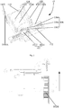
Fig. 1 illustrates a structural schematic diagram of an initial state of an automatic switching device in accordance with one embodiment of the present disclosure; -
Fig. 2 illustrates a structural schematic diagram of an extended state of the automatic switching device in accordance with one embodiment of the present disclosure; -
Fig. 3 illustrates a schematic top view of the automatic switching device inFig. 2 ; -
Fig. 4 illustrates a structural schematic diagram of a reset state of the automatic switching device in accordance with one embodiment of the present disclosure; -
Fig. 5 illustrates a structural schematic diagram of an extended state of the automatic switching device in accordance with one embodiment of the present disclosure; -
Fig. 6 illustrates a schematic side view of the automatic switching device inFig. 5 ; -
Fig. 7 illustrates a structural schematic diagram after retraction of the transmission gear in the automatic switching device inFig. 6 ; -
Fig. 8 illustrates a schematic side view of the automatic switching device inFig. 7 ; -
Fig. 9 illustrates a structural schematic diagram after reset of the rack in the automatic switching device inFig. 7 ; -
Fig. 10 illustrates a structural schematic diagram of a refrigeration device in accordance with one embodiment of the present disclosure; -
Fig. 11 illustrates a structural schematic diagram of a refrigeration device in accordance with another embodiment of the present disclosure. - The corresponding relationship between reference signs and component names in
Fig. 1 to Fig. 11 is as follows:
10: automatic switching device, 20: cabinet body, 30: door body, 102: ejection structure, 1022: transmission gear, 1024: rack, 104: driving device, 106: auxiliary control device, 1062: inductor, 1064: first induction switch, 1066: second induction switch, 108: box body, 1082: first receiving portion, 1084: second receiving portion, 1082A: notch, 110: sliding portion, 1084A: chute, 1102: paddle, 112: elastomer, 1042: driving motor, 1044: reductiongearbox, 1: refrigeration device. - In order to understand the above objectives, features and advantages of the present disclosure more clearly, the present disclosure will be further described in detail below in combination with drawings. It should be noted that the embodiments of the present application and the features in the embodiments may be combined with each other without conflicts.
- In the following description, numerous specific details are set forth in order to provide a full understanding of the present disclosure, but the present disclosure may be practiced otherwise than as described herein. Therefore, the protection scope of the present disclosure is not limited by specific embodiments disclosed below.
- The automatic switching device according to some embodiments of the present disclosure are described below with reference to
Fig. 1 to Fig. 9 . - As shown in
Fig. 1 to Fig. 4 , an automatic switching device 10 according to a first embodiment of the present disclosure is applicable to a refrigeration device, which comprises a cabinet body 20 and a door body 30 connected with the cabinet body 20, wherein, the automatic switching device 10 is installed on the cabinet body 20; the automatic switching device 10 comprises: an ejection structure 102, comprising a transmission gear 1022 and a rack 1024 matching the transmission gear 1022 in transmission; a driving device 104, connected to the transmission gear 1022 and used for driving the transmission gear 1022 to rotate, so as to drive the rack 1024 to protrude to open the door body 30 or to retract to close the door body 30; and an auxiliary control device 106 comprising an inductor 1062 arranged on the rack 1024, a first induction switch 1064 and a second induction switch 1066, the first induction switch 1064 and the second induction switch 1066 being connected to the driving device 104 respectively; as shown inFig. 3 , when the inductor 1062 moves to the position of the first induction switch 1064, by generating a first control signal, the first induction switch 1064 controls the driving device 104 to stop working so as to cause the door body 30 to be in an opened state; and as shown inFig. 4 , when the inductor 1062 moves to the position of the second induction switch 1066, by generating a second control signal, the second induction switch 1066 controls the driving device 104 to stop working so as to cause the door body 30 to reset to a closed state. - In the technical solution, the
automatic switching device 10 is arranged on thecabinet body 20 of the refrigeration device; theautomatic switching device 10 comprises theejection structure 102, the drivingdevice 104 and theauxiliary control device 106, wherein theejection structure 102 comprises astraight transmission gear 1022 and arack 1024 matching thestraight transmission gear 1022, the drivingdevice 104 drives thetransmission gear 1022 to rotate positively to realize forward movement of therack 1024 engaged with thetransmission gear 1022 and open thedoor body 30 through ejection, and thedriving device 104 drives thetransmission gear 1022 to rotate reversely to realize backward movement of therack 1024 engaged with thetransmission gear 1022 so as to cause thedoor body 30 to reset to be closed. - The
inductor 1062 is arranged on therack 1024, and can move forwards and backwards along with therack 1024, thefirst induction switch 1064 and thesecond induction switch 1066 are respectively arranged at specified positions on the moving path of therack 1024, and thefirst induction switch 1064 is closer to thedoor body 30 than thesecond induction switch 1066. When theintroducer 1062 moves to the position of thefirst induction switch 1064 along with therack 1024, by inducing with thefirst induction switch 1064, thefirst induction switch 1064 generates the first control signal to control thedriving device 104 to stop working; at this time, therack 1024 extends out to open thedoor body 30, thedoor body 30 is in an opened state, and thesecond induction switch 1066 is activated to work. After a specified period of time, the drivingdevice 104 drives thetransmission gear 1022 to rotate reversely, so that therack 1024 moves in a reverse direction (as shown by the direction of the arrow inFig. 3 ) until theinductor 1062 induces with thesecond induction switch 1066, and thesecond induction switch 1066 generates the second control signal to control thedriving device 104 to stop working so as to cause thedoor body 30 to reset to be closed. - The stroke of the
rack 1024 can be controlled by arranging the induction switches while automatic opening and closing of thedoor body 30 are realized. When the maximum stroke is reached, that is, when thefirst induction switch 1064 is triggered to generate an induction signal to keep thedoor body 30 in the open state for a specified period of time, thedoor body 30 is automatically closed. On the one hand, after thedoor body 30 is opened, thedoor body 30 is automatically in an opened state because therack 1024 is in the extended state, and no external force is required for keeping the state; and on the other hand, as thetransmission gear 1022 adopts standard parts, the production cost is low, the induction switches are arranged to realize the controllable stroke, the drivingdevice 104 is automatically controlled after a specified stroke is completed, and the control precision is high. - The induction switch may be a switch based on electromagnetic induction or a switch based on infrared induction, microwave induction or photoelectric induction.
- The
automatic switching device 10 may be either individually arranged at the upper or lower end of thecabinet body 20 or respectively arranged at the upper and lower ends of thecabinet body 20. - In addition, the
automatic switching device 10 in the above embodiment provided by the present disclosure may also have the following additional technical features. - As shown in
Fig. 1 to Fig. 4 , in the above technical solution, preferably, the automatic switching device further comprises abox body 108 installed on thecabinet body 20, wherein thebox body 108 comprises afirst receiving portion 1082 and asecond receiving portion 1084; therack 1024, thefirst induction switch 1064 and thesecond induction switch 1066 are installed in thefirst receiving portion 1082, a sidewall of thefirst receiving portion 1082 opposite to thedoor body 30 is provided with anotch 1082A, and therack 1024 extends out of thenotch 1082A to eject thedoor body 30 out; thedriving device 104 is installed in thesecond receiving portion 1084; and thefirst induction switch 1064 is closer to thenotch 1082A than thesecond induction switch 1066. - In the above technical solution, the
automatic switching device 10 further comprises abox body 108 arranged outside and functioning for containing, wherein specifically, thebox body 108 comprises afirst receiving portion 1082 and asecond receiving portion 1084; thefirst receiving portion 1082 is used for installing therack 1024, thefirst induction switch 1064 and thesecond induction switch 1066, a sidewall of thefirst receiving portion 1082 opposite to thedoor body 30 is provided with thenotch 1082A, and thefirst induction switch 1064 is closer to thenotch 1082A than thesecond induction switch 1066. Therack 1024 extends out of thenotch 1082A to eject thedoor body 30 out to realize automatic opening of thedoor body 30. Thebox body 108 is arranged to realize integral modularized assembly of theejection structure 102, the drivingdevice 104 and theauxiliary control device 106, so that the assembly process is simplified and the disassembly is convenient; and thebox body 108 is arranged, which is beneficial to improving the assembly strength of theautomatic switching device 10 and prolonging the service life. - As shown in
Fig. 1 to Fig. 9 , in any one of the above technical solutions, preferably, the automatic switching device further comprises a slidingportion 110, arranged in thesecond receiving portion 1084 and connected to thedriving device 104, wherein the side wall of thesecond receiving portion 1084 opposite to thedoor body 30 is provided with achute 1084A; apaddle 1102 is arranged at a position where the slidingportion 110 matches thechute 1084A, as shown inFig. 6 , thepaddle 1102 extends to the outside of thesecond receiving portion 1084 by thechute 1084A, and thepaddle 1102 drives thetransmission gear 1022 to disengage from therack 1024 when being subjected to an external force. - In the technical solution, by arranging the sliding
portion 110 in thesecond receiving portion 1084 and connecting the slidingportion 110 to thedriving device 104, the drivingdevice 104 moves forwards and backwards when the slidingportion 110 slides forwards and backwards. Moreover, thechute 1084A is arranged on the side wall of thesecond receiving portion 1084 opposite to thedoor body 30, thepaddle 1102 capable of moving along thechute 1084A is arranged at a position where the slidingportion 110 matches thechute 1084A. When the automatic door opening function or automatic door closing function of theautomatic switching device 10 is abnormal, thepaddle 1102 is stirred manually to drive the drivingdevice 104 to retreat until thetransmission gear 1022 disengages from therack 1024, and then therack 1024 is reset to realize manual closing of thedoor body 30, thereby preventing the condition that thedoor body 30 cannot be closed when an abnormal condition occurs. - As shown in
Fig. 5 and Fig. 6 , specifically, when an abnormal condition (such as fault of thedriving device 104, power off, etc.) occurs to theejection structure 102, therack 1024 and thetransmission gear 1022 stop urgently in a moving state, and if therack 1024 has extended a certain length at this moment, thedoor body 30 cannot be normally closed. As thepaddle 1102, the slidingportion 110, and thedriving device 104 can be regarded as a whole, as shown by the direction of the arrow inFig. 6 , by stirring thepaddle 1102, thepaddle 1102 slides along thechute 1084A until thedriving device 104 drives thetransmission gear 1022 to disengage from therack 1024, therack 1024 is manually reset, and then thecorresponding door body 30 can be manually closed. - In any one of the above technical solutions, preferably, the area on the
cabinet body 20 away from the connection portion of thecabinet body 20 and thedoor body 30 is provided with a containing groove (not shown), and thebox body 108 is arranged in the containing groove. - In the technical solution, the containing groove is arranged on the
cabinet body 20 to install thebox body 108. On the one hand, the overall good appearance of the refrigeration device can be prevented from being affected by theautomatic switching device 10, and on the other hand, the containing groove is formed at a position away from the connection portion (such as a hinge, etc.) of thecabinet body 20 and thedoor body 30, so that the ejection operation is easier. - In any one of the above technical solutions, preferably, the area of the
rack 1024 opposite to thenotch 1082A is provided with an elastic portion (not shown). - In the technical solution, by arranging the elastic portion in the area of the
rack 1024 opposite to thenotch 1082A, when therack 1024 abuts against thedoor body 30, the elastic portion generates elastic deformation, so that soft contact between therack 1024 and thedoor body 30 is achieved to prevent generation of a dent when therack 1024 abuts against thedoor body 30. - Moreover, the elastic portion may also be arranged in an area opposite to the
door body 30. - Specifically, the elastic portion is a rubber fitting.
- As shown in
Fig. 5, Fig. 7 andFig. 9 , in any one of the above technical solutions, the automatic switching device further comprises anelastomer 112, of which one end is connected to thefirst receiving portion 1082 and the other end is connected to therack 1024, wherein theelastomer 112 is used for pulling therack 1024 back to reset after the transmission gear1022 disengages from therack 1024. - In the technical solution, by arranging the
elastomer 112 in thefirst receiving portion 1082, connecting one end of theelastomer 112 to thefirst receiving portion 1082 and connecting the other end of theelastomer 112 to therack 1024, theelastomer 112 is in a tension state when therack 1024 moves towards the direction of thedoor body 30, and in the case that thedoor body 30 needs to be closed manually when theautomatic switching device 10 is abnormal, therack 1024 is pulled back to reset through resilience of theelastomer 112, thus simplifying operation of users. - Specifically, the elastomer is a spring.
- As shown in
Fig. 1 to Fig. 4 , in any one of the above technical solutions, preferably, the drivingdevice 104 comprises a drivingmotor 1042, areduction gearbox 1044 connected to the drivingmotor 1042, wherein the free end of thereduction gearbox 1044 is provided with a rotating shaft, and thedriving device 104 is connected to thetransmission gear 1022 through the rotating shaft to drive thetransmission gear 1022 to rotate. - In the technical solution, the driving
device 104 comprises a drivingmotor 1042 and a reduction gearbox1044, and the free end of thereduction gearbox 1044 is provided with a rotating shaft matching thetransmission gear 1022. The rotating shaft drives thetransmission gear 1022 to rotate through matching of the drivingmotor 1042 and thereduction gearbox 1044 to drive therack 1024 to move, thereby being capable of reducing the rotating speed, preventing intense wear and noise between thetransmission gear 1022 and therack 1024 resulted from too fast rotation of thetransmission gear 1022, and improving the service lives of thetransmission gear 1022 and therack 1024. - As shown in
Fig. 1 , in any one of the above technical solutions, preferably, theinductor 1062 is a magnet, thefirst induction switch 1064 is a first Hall switch, and thesecond induction switch 1066 is a second Hall switch, wherein when the magnet and the first Hall switch send electromagnetic induction, the first Hall switch generates the first control signal, and when the magnet and the second Hall switch send electromagnetic induction, the second Hall switch generates the second control signal. - In the technical solution, by arranging the
inductor 1062 as a magnet and arranging both thefirst induction switch 1064 and thesecond induction switch 1066 as Hall switches, when the magnetic field of the magnet on therack 1024 is induced by the first Hall switch, the first Hall switch outputs the first control signal to a control circuit, and the control circuit cuts off the power of the drivingmotor 1042 according to the received first control signal to realize ejection and hovering of therack 1024 to open thedoor body 30 through ejection. - After a predetermined period of time, by inputting a reverse current to the driving
motor 1042, the drivingmotor 1042 drives thetransmission gear 1022 to rotate reversely, thetransmission gear 1022 drives therack 1024 to move in an opposite direction until the magnet on therack 1024 is induced by the second Hall switch, the second Hall switch outputs the second control signal to the control circuit, and the control circuit cuts off the power of the drivingmotor 1042 to reset the entire device. - An electromagnetic induction method is adopted to realize a controllable stroke. Compared with infrared induction, photoelectric induction and other methods, the electromagnetic induction method is low in cost, high in reliability, and easy to apply.
- In any one of the above technical solutions, preferably, the automatic switching device further comprises a touch switch (not shown) arranged on a handle area of the
door body 30, wherein the touch switch is connected to thedriving device 104. - In the technical solution, by arranging the touch switch on the handle of the
door body 30 and connecting the touch switch to thedriving device 104, when the user needs to open the door, by touching the touch switch, the drivingdevice 104 starts operation to drive thetransmission gear 1022 to rotate so as to drive therack 1024 to eject thedoor body 30 out. When arriving at the area of the first Hall switch, the magnet sends the first control signal by generating electromagnetic induction with the first Hall switch; at this time, the drivingdevice 104 stops working, and after a specified period of time or through touching the touch switch again by the user, thetransmission gear 1022 rotates reversely to drive therack 1024 to retreat so as to realize reset of thedoor body 30, which is convenient to operate. - In addition, the touch switch may also be replaced by an induction switch or a voice operated switch or the like.
- In any one of the above technical solutions, preferably, the automatic switching device further comprises a door closer (not shown) arranged on the connecting portion, wherein the door closer comprises a torsion ring for realizing reset of the
rack 1024 by rebounding after therack 1024 protrudes to open thedoor body 30. - In the technical solution, by adding the torsion ring on the connection portion to serve as the door closer, in a door opening process, the torsion spring accumulates elastic potential energy through elastic deformation, and in a door closing process, the torsion spring releases elastic potential energy through recovery to the original state to further realize automatic closing of the
door body 30. - As shown in
Fig. 1 to Fig. 4 , an automatic switching device 10 according to a second embodiment of the present disclosure is applicable to a refrigeration device, which comprises a cabinet body 20 and a door body 30 in connection with the cabinet body 20, wherein, the automatic switching device 10 is installed on the door body 30; the automatic switching device 10 comprises: an ejection structure 102, comprising a transmission gear 1022 and a rack 1024 matching the transmission gear 1022 in transmission; a driving device 104, connected to the transmission gear 1022 and used for driving the transmission gear 1022 to rotate, so as to drive the rack 1024 to protrude to open the door body 30 or to retract to close the door body 30; and an auxiliary control device 106 comprising an inductor 1062 arranged on the rack 1024, a first induction switch 1064 and a second induction switch 1066, the first induction switch 1064 and the second induction switch 1066 being connected to the driving device 104 respectively; as shown inFig. 4 , when the inductor 1062 moves to the position of the first induction switch 1064, by generating a first control signal, the first induction switch 1064 controls the driving device 104 to stop working so as to cause the door body 30 to be in an opened state; and as shown inFig. 4 , when the inductor 1062 moves to the position of the second induction switch 1066, by generating a second control signal, the second induction switch 1066 controls the driving device 104 to stop working so as to cause the door body 30 to reset to a closed state. - In the technical solution, the
automatic switching device 10 is arranged on thedoor body 30 of the refrigeration device; theautomatic switching device 10 comprises theejection structure 102, the drivingdevice 104 and theauxiliary control device 106, wherein theejection structure 102 comprises astraight transmission gear 1022 and arack 1024 matching thestraight transmission gear 1022, the drivingdevice 104 drives thetransmission gear 1022 to rotate positively to realize forward movement of therack 1024 engaged with thetransmission gear 1022 and open thedoor body 30 through ejection by abutting against thecabinet body 20, and thedriving device 104 drives thetransmission gear 1022 to rotate reversely to realize backward movement of therack 1024 engaged with thetransmission gear 1022 so as to cause thedoor body 30 to reset to be closed. - The
inductor 1062 is arranged on therack 1024, and can move forwards and backwards along with therack 1024, thefirst induction switch 1064 and thesecond induction switch 1066 are respectively arranged at specified positions on the moving path of therack 1024, and thefirst induction switch 1064 is closer to thecabinet body 20 than thesecond induction switch 1066. When theintroducer 1062 moves to the position of thefirst induction switch 1064 along with therack 1024, by inducing with thefirst induction switch 1064, thefirst induction switch 1064 generates the first control signal to control thedriving device 104 to stop working; at this time, therack 1024 extends out to open thedoor body 30, thedoor body 30 is in an opened state, and thesecond induction switch 1066 is activated to work. After a specified period of time, the drivingdevice 104 drives thetransmission gear 1022 to rotate reversely, so that therack 1024 moves in a reverse direction (as shown by the direction of the arrow inFig. 3 ) until theinductor 1062 induces with thesecond induction switch 1066, and thesecond induction switch 1066 generates the second control signal to control thedriving device 104 to stop working so as to cause thedoor body 30 to reset to be closed. - The stroke of the
rack 1024 can be controlled by arranging the induction switches while automatic opening and closing of thedoor body 30 are realized. When the maximum stroke is reached, that is, when thefirst induction switch 1064 is triggered to generate an induction signal to keep thedoor body 30 in the open state for a specified period of time, thedoor body 30 is automatically closed. On the one hand, after thedoor body 30 is opened, thedoor body 30 is automatically in an opened state because therack 1024 is in the extended state, and no external force is required for keeping the state; and on the other hand, as thetransmission gear 1022 adopts standard parts, the production cost is low, the induction switches are arranged to realize the controllable stroke, the drivingdevice 104 is automatically controlled to stop working after a specified stroke is completed, and the control precision is high. - The induction switch may be a switch based on electromagnetic induction or a switch based on infrared induction, microwave induction or photoelectric induction.
- The
automatic switching device 10 may be either individually arranged at the upper or lower end of thecabinet body 20 or respectively arranged at the upper and lower ends of thecabinet body 20. - As shown in
Fig. 1 to Fig. 4 , in any one of the above technical solutions, preferably, the automatic switching device further comprises abox body 108 installed on thedoor body 30, wherein thebox body 108 comprises afirst receiving portion 1082 and asecond receiving portion 1084; therack 1024, thefirst induction switch 1064 and thesecond induction switch 1066 are installed in thefirst receiving portion 1082, a sidewall of thefirst receiving portion 1082 opposite to thecabinet body 20 is provided with anotch 1082A, and therack 1024 extends out of thenotch 1082A to eject thedoor body 30 out; thedriving device 104 is installed in thesecond receiving portion 1084; and thefirst induction switch 1064 is closer to thenotch 1082A than thesecond induction switch 1066. - In the above technical solution, the
automatic switching device 10 further comprises abox body 108 arranged outside and functioning for containing, wherein specifically, thebox body 108 comprises afirst receiving portion 1082 and asecond receiving portion 1084; thefirst receiving portion 1082 is used for installing therack 1024, thefirst induction switch 1064 and thesecond induction switch 1066, a sidewall of thefirst receiving portion 1082 opposite to thedoor body 30 is provided with anotch 1082A, and thefirst induction switch 1064 is closer to thenotch 1082A than thesecond induction switch 1066. Therack 1024 extends out of thenotch 1082A to eject thedoor body 30 out to realize automatic opening of thedoor body 30. Thebox body 108 is arranged to realize integral modularized assembly of theejection structure 102, the drivingdevice 104 and theauxiliary control device 106, so that the assembly process is simplified and the disassembly is convenient; and thebox body 108 is arranged, which is beneficial to improving the assembly strength of theautomatic switching device 10 and prolonging the service life. - As shown in
Fig. 1 to Fig. 9 , in any one of the above technical solutions, preferably, the automatic switching device further comprises a slidingportion 110, arranged in thesecond receiving portion 1084 and connected to thedriving device 104, wherein the side wall of thesecond receiving portion 1084 opposite to thecabinet body 20 is provided with achute 1084A; apaddle 1102 is arranged at a position where the slidingportion 110 matches thechute 1084A, as shown inFig. 6 , thepaddle 1102 extends to the outside of thesecond receiving portion 1084 by thechute 1084A, and thepaddle 1102 drives thetransmission gear 1022 to disengage from therack 1024 when being subjected to an external force. - In the technical solution, by arranging the sliding
portion 110 in thesecond receiving portion 1084 and connecting the slidingportion 110 to thedriving device 104, when sliding forwards and backwards, the slidingportion 110 drives thedriving device 104 to move forwards and backwards. Moreover, thechute 1084A is arranged on the side wall of thesecond receiving portion 1084 opposite to thecabinet body 20, thepaddle 1102 capable of moving along thechute 1084A is arranged at a position where the slidingportion 110 matches thechute 1084A. When the automatic door opening function or automatic door closing function of theautomatic switching device 10 is abnormal, thepaddle 1102 is stirred manually to drive the drivingdevice 104 to retreat until thetransmission gear 1022 disengages from therack 1024, and then therack 1024 is reset to realize manual closing of thedoor body 30, thereby preventing the condition that thedoor body 30 cannot be closed when an abnormal condition occurs. - As shown in
Fig. 5 and Fig. 6 , specifically, when an abnormal condition (such as fault of thedriving device 104, power off, etc.) occurs to theejection structure 102, therack 1024 and thetransmission gear 1022 stop urgently in a moving state, and if therack 1024 has extended a certain length at this moment, thedoor body 30 cannot be normally closed. As thepaddle 1102, the slidingportion 110, and thedriving device 104 can be regarded as a whole, as shown by the direction of the arrow inFig. 6 , by stirring thepaddle 1102, thepaddle 1102 slides along thechute 1084A until thedriving device 104 drives thetransmission gear 1022 to disengage from therack 1024, therack 1024 is manually reset, and then thecorresponding door body 30 can be manually closed. - In any one of the above technical solutions, preferably, the area on the
door body 30 away from the connection portion of thecabinet body 20 and thedoor body 30 is provided with a containing groove (not shown), and thebox body 108 is arranged in the containing groove. - In the technical solution, the containing groove is arranged on the
door body 30 to install thebox body 108. On the one hand, the overall good appearance of the refrigeration device can be prevented from being affected by theautomatic switching device 10, and on the other hand, the containing groove is formed at a position away from the connection portion (such as a hinge, etc.) of thecabinet body 20 and thedoor body 30, so that the ejection operation is easier. - In any one of the above technical solutions, preferably, the area of the
rack 1024 opposite to thenotch 1082A is provided with an elastic portion (not shown). - In the technical solution, by arranging the elastic portion in the area of the
rack 1024 opposite to thenotch 1082A, when therack 1024 abuts against thecabinet body 20, the elastic portion generates elastic deformation, so that soft contact between therack 1024 and thecabinet body 20 is achieved to prevent generation of a dent when therack 1024 abuts against thecabinet body 20. - Moreover, the elastic portion may also be arranged in an area opposite to the
cabinet body 20. - Specifically, the elastic portion is a rubber fitting.
- As shown in
Fig. 5, Fig. 7 andFig. 9 , in any one of the above technical solutions, the automatic switching device further comprises anelastomer 112, of which one end is connected to thefirst receiving portion 1082 and the other end is connected to therack 1024, wherein theelastomer 112 is used for pulling therack 1024 back to reset after the transmission gear1022 disengages from therack 1024. - In the technical solution, by arranging the
elastomer 112 in thefirst receiving portion 1082, connecting one end of theelastomer 112 to thefirst receiving portion 1082 and connecting the other end of the elastomer to therack 1024, theelastomer 112 is in a tension state when therack 1024 moves towards the direction of thedoor body 30, and in the case that thedoor body 30 needs to be closed manually when theautomatic switching device 10 is abnormal, therack 1024 is pulled back to reset through resilience of theelastomer 112, thus simplifying operation of users. - Specifically, the
elastomer 112 is a spring. - As shown in
Fig. 1 to Fig. 4 , in any one of the above technical solutions, preferably, the drivingdevice 104 comprises a drivingmotor 1042, areduction gearbox 1044 connected to the drivingmotor 1042, wherein the free end of thereduction gearbox 1044 is provided with a rotating shaft, and thedriving device 104 is connected to thetransmission gear 1022 through the rotating shaft to drive thetransmission gear 1022 to rotate. - In the technical solution, the driving
device 104 comprises a drivingmotor 1042 and areduction gearbox 1044, and the free end of thereduction gearbox 1044 is provided with a rotating shaft matching thetransmission gear 1022. The rotating shaft drives thetransmission gear 1022 to rotate through matching of the drivingmotor 1042 and thereduction gearbox 1044 to drive therack 1024 to move, thereby being capable of reducing the rotating speed, preventing intense wear and noise between thetransmission gear 1022 and therack 1024 resulted from too fast rotation of thetransmission gear 1022, and improving the service lives of thetransmission gear 1022 and therack 1024. - As shown in
Fig. 1 , in any one of the above technical solutions, preferably, theinductor 1062 is a magnet, thefirst induction switch 1064 is a first Hall switch, and thesecond induction switch 1066 is a second Hall switch, wherein when the magnet and the first Hall switch send electromagnetic induction, the first Hall switch generates the first control signal, and when the magnet and the second Hall switch send electromagnetic induction, the second Hall switch generates the second control signal. - In the technical solution, by arranging the
inductor 1062 as a magnet and arranging both thefirst induction switch 1064 and thesecond induction switch 1066 as Hall switches, when the magnetic field of the magnet on therack 1024 is induced by the first Hall switch, the first Hall switch outputs the first control signal to a control circuit, and the control circuit cuts off the power of the drivingmotor 1042 according to the received first control signal to realize ejection and hovering of therack 1024 to open thedoor body 30 through ejection. - After a predetermined period of time, by inputting a reverse current to the driving
motor 1042, the drivingmotor 1042 drives thetransmission gear 1022 to rotate reversely, thetransmission gear 1022 drives therack 1024 to move in an opposite direction until the magnet on therack 1024 is induced by the second Hall switch, the second Hall switch outputs the second control signal to the control circuit, and the control circuit cuts off the power of the drivingmotor 1042 to reset the entire device. - An electromagnetic induction method is adopted to realize a controllable stroke. Compared with infrared induction, photoelectric induction and other methods, the electromagnetic induction method is low in cost, high in reliability, and easy to apply.
- In any one of the above technical solutions, preferably, the automatic switching device further comprises a touch switch (not shown) arranged on a handle area of the
door body 30, wherein the touch switch is connected to thedriving device 104. - In the technical solution, by arranging the touch switch on the handle of the
door body 30 and connecting the touch switch to thedriving device 104, when the user needs to open the door, by touching the touch switch, the drivingdevice 104 starts operation to drive thetransmission gear 1022 to rotate so as to drive therack 1024 to eject thedoor body 30 out. When arriving at the area of the first Hall switch, the magnet sends the first control signal by generating electromagnetic induction with the first Hall switch; at this time, the drivingdevice 104 stops working, and after a specified period of time or through touching the touch switch again by the user, thetransmission gear 1022 rotates reversely to drive therack 1024 to retreat so as to realize reset of thedoor body 30, which is convenient to operate. - In addition, the touch switch may also be replaced by an induction switch or a voice operated switch or the like.
- In any one of the above technical solutions, preferably, the automatic switching device further comprises a door closer (not shown) arranged on the connecting portion, wherein the door closer comprises a torsion ring for realizing reset of the
rack 1024 by rebounding after therack 1024 protrudes to open thedoor body 30. - In the technical solution, by adding the torsion ring on the connection portion to serve as the door closer, in a door opening process, the torsion spring accumulates elastic potential energy through elastic deformation, and in a door closing process, the torsion spring releases elastic potential energy through recovery to the original state to further realize automatic closing of the
door body 30. -
Fig. 10 andFig. 11 illustrates a refrigeration device in accordance with some embodiments of the present disclosure. - As shown in
Fig. 10 andFig. 11 , an embodiment of the third aspect of the present disclosure provides a refrigeration device 1 comprising theautomatic switching device 10 of any one of the first or second aspect of the present disclosure. - The refrigeration device 1 provided by the embodiment of the second aspect of the present disclosure comprises the
automatic switching device 10 of any one of the first or second aspect of the present disclosure, and thus has all beneficial effects of the aboveautomatic switching device 10, which are not be repeated herein. - In the present disclosure, the terms "first,""second," and "third" are used for the purpose of description only, and cannot be construed as indicating or implying the relative importance; the term "plurality" means two or more, unless otherwise explicitly defined. The terms "installation", "connected,""connection,""fixed" and the like should be understood broadly. For example, "connection" may be a fixed connection, and may also be detachable connection or an integral connection; and "connected" may be either directly connected or connected through an intermediary. For the person skilled in the art, the specific meanings of the above terms in the present disclosure may be understood in accordance with specific conditions.
- In the description of the present disclosure, it should be understood that the orientation or positional relationships indicated by the terms "upper,""lower,""left,""right,""front,""back" and the like based on the orientation or positional relationships shown in the drawings, are merely for the convenience of the description of the present disclosure rather than indicating or implying that the devices or units referred to may have specific orientations, are constructed and operated in the specific orientations, and thus cannot be construed as limitations to the present disclosure.
- In the description of the present specification, the description of the terms "one embodiment,""some embodiments,""specific embodiments" and the like means that the specific features, structures, materials or characteristics described in combination with the embodiments or examples are comprised in at least one embodiment or example of the present embodiment. In the present specification, the schematic representation of the above terms does not necessarily refer to the same embodiment or example. In addition, the specific features, structures, materials or characteristics described may be combined in an appropriate way in any one or more embodiments or examples.
- The above descriptions are only preferred embodiments of the present disclosure, and are not intended to limit the present disclosure. Various modifications and variations may be made to the present disclosure for the person skilled in the art. Any modifications, equivalent substitutions, improvements and the like made within the spirit and principle of the present invention should be encompassed within the protection scope of the present disclosure.
Claims (15)
- An automatic switching device (10) for a refrigeration device (1), the refrigeration device (1) including a cabinet body (20) and a door body (30) connected with the cabinet body (20), characterized in that, the automatic switching device (10) is installed on the cabinet body (20), and the automatic switching device (10) comprising:an ejection structure (102) including a transmission gear (1022) and a rack (1024) matching the transmission gear (1022) in transmission;a driving device (104), connected to the transmission gear (1022) and configured to drive the transmission gear (1022) to rotate, so as to drive the rack (1024) to protrude to open the door body (30) or to retract to close the door body (30); andan auxiliary control device (106) including an inductor (1062), a first induction switch (1064) and a second induction switch (1066), the inductor (1062) being arranged on the rack (1024), the first induction switch (1064) and the second induction switch (1066) being connected to the driving device (104) respectively;wherein, in a case that the inductor (1062) moves to a position adjacent to the first induction switch (1064), the first induction switch (1064) generates a first control signal, which controls the driving device (104) to stop driving so as to cause the door body (30) to remain in an opened state; and in a case that the inductor (1062) moves to a position adjacent to the second induction switch (1066), the second induction switch (1066) generates a second control signal, which controls the driving device (104) to stop driving so as to cause the door body (30) to reset to a closed state.
- The automatic switching device (10) of claim 1, further comprising:a box body (108) configured to be installed on the cabinet body (20), the box body (108) including a first receiving portion (1082) and a second receiving portion (1084);the rack (1024), the first induction switch (1064) and the second induction switch (1066) are positioned in the first receiving portion (1082), a sidewall of the first receiving portion (1082) opposite to the door body (30) includes a notch (1082A), and the rack (1024) extends through the notch (1082A) to eject the door body (30);the driving device (104) is positioned in the second receiving portion (1084); andthe first induction switch (1064) is closer to the notch (1082A) than the second induction switch (1066).
- The automatic switching device (10) of any of preceding claims, further comprising:a sliding portion (110) arranged in the second receiving portion (1084) and connected to the driving device (104);a chute (1084A) positioned on a side wall of the second receiving portion (1084) opposite to the door body (30); anda paddle (1102) arranged at a position where the sliding portion (110) matches the chute (1084A), the paddle (1102) extending out of the second receiving portion (1084) through the chute (1084A),wherein the paddle (1084A) drives the transmission gear (1022) to disengage from the rack (1024) in a case that the paddle (1084A) is subjected to an external force.
- The automatic switching device (10) of claim 2, wherein the box body (108) is configured to be positioned in a containing groove on the cabinet body (20), the containing groove being arranged away from a connection portion between the cabinet body (20) and the door body (30).
- An automatic switching device (10) for a refrigeration device (1), the refrigerator device (1) having a cabinet body (20) and a door body (30) connected with the cabinet body (20), characterized in that, the automatic switching device (10) is installed on the door body (30) and the automatic switching device (10) comprising:an ejection structure (102) including a transmission gear (1022) and a rack (1024) matching the transmission gear (1022) in transmission;a driving device (104), connected to the transmission gear (1022) and configured to drive the transmission gear (1022) to rotate, so as to drive the rack (1024) to protrude or to retract; andan auxiliary control device (106) including an inductor (1062), a first induction switch (1064) and a second induction switch (1066), the inductor (1062) being arranged on the rack (1024), the first induction switch (1064) and the second induction switch (1066) being connected to the driving device (104) respectively;wherein, in a case that the inductor (1062) moves to a position adjacent to the first induction switch (1064), the first induction switch (1064) generates a first control signal, which controls the driving device (104) to stop driving so as to cause the door body (30) to remain in an opened state; and in a case that the inductor (1062) moves to a position adjacent to the second induction switch (1066), the second induction switch (1066) generates a second control signal, which controls the driving device (104) to stop driving so as to cause the door body (30) to reset to a closed state.
- The automatic switching device (10) of claim 5, further comprising:a box body (108) configured to be installed on the door body (30), the box body (108) including a first receiving portion (1082) and a second receiving portion (1084);the rack (1024), the first induction switch (1064) and the second induction switch (1066) are positioned in the first receiving portion (1082), a sidewall of the first receiving portion (1082) opposite to the cabinet body (20) includes a notch (1082A), and the rack (1024) extends through the notch (1082A) to eject the door body (30);the driving device (104) is positioned in the second receiving portion (1084); andthe first induction switch (1064) is closer to the notch (1082A) than the second induction switch (1066).
- The automatic switching device (10) of claim 5 or 6, further comprising:a sliding portion (110) arranged in the second receiving portion (1084) and connected to the driving device (104),a chute (1084A) positioned on a side wall of the second receiving portion (1084) opposite to the cabinet body (20); anda paddle (1102) arranged at a position where the sliding portion (110) matches the chute (1084A), the paddle (1102) extending out of the second receiving portion (1084) through the chute (1084A),wherein the paddle (1102) drives the transmission gear (1022) to disengage from the rack (1024) in a case that the paddle (1102) is subjected to an external force.
- The automatic switching device (10) of claim 6, wherein,
the box body (108) is configured to be positioned in a containing groove on the door body (30), the containing groove being arranged away from a connection portion between the cabinet body (20) and the door body (30). - The automatic switching device (10) of claim 2 or 6, wherein,
an area of the rack (1024) opposite to the notch (1082A) includes an elastic portion. - The automatic switching device (10) of claim 2 or 6, further comprising:an elastomer (112), a first end of the elastomer (112) being connected to the first receiving portion (1082), and a second end of the elastomer (112) being connected to the rack (1024),wherein the elastomer (112) is configured to pull the rack (1024) back to reset after the transmission gear (1022) disengages from the rack (1024).
- The automatic switching device (10) of claim 1 or 5, wherein,
the driving device (104) includes a driving motor (1042) and a reduction gearbox (1044) connected to the driving motor (1042);
a free end of the reduction gearbox (1044) includes a rotating shaft; and
the driving device (104) is connected to the transmission gear (1022) through the rotating shaft to drive the transmission gear (1022) to rotate. - The automatic switching device (10) of claim 1 or 5, wherein,
the inductor (1062) is a magnet, the first induction switch (1064) is a first Hall switch, and the second induction switch (1066) is a second Hall switch,
wherein in a case that an electromagnetic induction is occurring between the magnet and the first Hall switch, the first Hall switch generates the first control signal, and wherein in a case that an electromagnetic induction is occurring between the magnet and the second Hall switch, the second Hall switch generates the second control signal. - The automatic switching device (10) of claim 1 or 5, further comprising:
a touch switch arranged on a handle area of the door body (30), and connected to the driving device (104). - The automatic switching device (10) of claim 4 or 8, further comprising:
a door closer arranged on the connection portion, the door closer including a torsion ring for realizing reset of the rack (1024) by rebounding after the rack (1024) protrudes to open the door body (30). - A refrigeration device (1), comprising the automatic switching device (10) of any one of claims 1-14.
Applications Claiming Priority (2)
| Application Number | Priority Date | Filing Date | Title |
|---|---|---|---|
| CN201611190248.4A CN106437391B (en) | 2016-12-21 | 2016-12-21 | Recloser and refrigeration plant |
| PCT/CN2017/075245 WO2018113093A1 (en) | 2016-12-21 | 2017-02-28 | Automatic switching device and refrigeration device |
Publications (2)
| Publication Number | Publication Date |
|---|---|
| EP3561212A1 true EP3561212A1 (en) | 2019-10-30 |
| EP3561212A4 EP3561212A4 (en) | 2020-01-15 |
Family
ID=58215223
Family Applications (1)
| Application Number | Title | Priority Date | Filing Date |
|---|---|---|---|
| EP17884318.1A Withdrawn EP3561212A4 (en) | 2016-12-21 | 2017-02-28 | AUTOMATIC SWITCHING AND REFRIGERATION DEVICES |
Country Status (6)
| Country | Link |
|---|---|
| US (1) | US11125005B2 (en) |
| EP (1) | EP3561212A4 (en) |
| JP (1) | JP6780119B2 (en) |
| KR (1) | KR102196194B1 (en) |
| CN (1) | CN106437391B (en) |
| WO (1) | WO2018113093A1 (en) |
Cited By (1)
| Publication number | Priority date | Publication date | Assignee | Title |
|---|---|---|---|---|
| WO2021167547A1 (en) * | 2020-02-20 | 2021-08-26 | Törk Maki̇ne Sanayi̇ Ve Ti̇caret Anoni̇m Şi̇rketi̇ | A dc motor actuator with position control |
Families Citing this family (31)
| Publication number | Priority date | Publication date | Assignee | Title |
|---|---|---|---|---|
| KR101897356B1 (en) * | 2016-11-03 | 2018-09-11 | 엘지전자 주식회사 | Refrigerator and a control method of the same |
| CN106437391B (en) | 2016-12-21 | 2018-03-16 | 合肥华凌股份有限公司 | Recloser and refrigeration plant |
| CN106761136B (en) * | 2016-12-27 | 2018-04-20 | 青岛海尔股份有限公司 | Automatic door operator and the refrigerator with the device |
| KR102490433B1 (en) * | 2017-04-24 | 2023-01-19 | 엘지전자 주식회사 | Refrigerator |
| CN107461983A (en) * | 2017-08-22 | 2017-12-12 | 佛山唯意电器有限公司 | A kind of refrigerating appliance with automatic switch door |
| CN107380042A (en) * | 2017-09-01 | 2017-11-24 | 衡阳泰豪通信车辆有限公司 | A kind of shelter |
| DE102017124282A1 (en) * | 2017-10-18 | 2019-04-18 | Kiekert Ag | Set-up device for a motor vehicle door |
| CN107798791B (en) * | 2017-11-16 | 2020-12-18 | 浙江如裕纺织科技股份有限公司 | Automatic door device of self-service library |
| CN110388784A (en) * | 2018-04-20 | 2019-10-29 | 青岛海尔智能技术研发有限公司 | Incude refrigerator, door opening method, device, equipment and the storage medium to open the door |
| CN110051308A (en) * | 2019-04-15 | 2019-07-26 | 华帝股份有限公司 | a dishwasher |
| CN112212592B (en) * | 2019-07-12 | 2022-02-15 | 海信(山东)冰箱有限公司 | A kind of refrigerator |
| CN112252889B (en) * | 2019-07-22 | 2022-02-11 | 海信(山东)冰箱有限公司 | Control method for opening and closing door device of refrigerator and refrigerator |
| CN112747545A (en) * | 2019-10-31 | 2021-05-04 | 佛山市云米电器科技有限公司 | Automatic door opening device and refrigerator |
| CN112826412B (en) * | 2019-11-22 | 2025-12-09 | 青岛海尔洗碗机有限公司 | Automatic ejection mechanism and dish washer |
| CN110965288B (en) * | 2019-11-25 | 2024-02-20 | 青岛海尔洗涤电器有限公司 | Door opening and closing device for laundry treatment equipment and laundry treatment equipment |
| CN112269350A (en) * | 2020-11-09 | 2021-01-26 | 燕山大学 | Automatic door opening device based on PLC discharges carbon monoxide gas |
| CN112520252B (en) * | 2020-11-28 | 2024-06-07 | 江苏威拉里新材料科技有限公司 | Environment-controllable storage equipment and storage technology for metal powder storage |
| CN114688817B (en) * | 2020-12-31 | 2023-03-17 | 青岛海尔电冰箱有限公司 | Automatic door opening and closing device for refrigerator and refrigerator with same |
| CN113029352B (en) * | 2021-03-16 | 2022-12-27 | 北京嘉达科技有限公司 | Multi-directional monitoring system for switch cabinet based on universal cradle head |
| CN115111831A (en) * | 2021-03-22 | 2022-09-27 | 宁波方太厨具有限公司 | Refrigerator and use control method thereof |
| CN113276780B (en) * | 2021-06-29 | 2025-08-12 | 裕克施乐塑料制品(太仓)有限公司 | Vehicle-mounted sliding type automatic storage box |
| CN113534700B (en) * | 2021-07-02 | 2025-08-08 | 上海珥智医疗科技有限公司 | Prosthesis manufacturing device control circuit and control method |
| CN113898266A (en) * | 2021-10-26 | 2022-01-07 | 裕克施乐塑料制品(太仓)有限公司 | Ejecting and rotating integrated automatic door opening and closing device |
| CN114301235A (en) * | 2022-01-05 | 2022-04-08 | 福禄堂(上海)生物科技有限公司 | Motor refrigeration equipment |
| CN114158218B (en) * | 2022-02-07 | 2022-04-19 | 山东万海电气科技有限公司 | Oil well frequency conversion cabinet with automatic inspection function |
| CN116624051A (en) * | 2022-02-14 | 2023-08-22 | 合肥美的电冰箱有限公司 | A door switch device and electrical equipment |
| CN114646484B (en) * | 2022-03-25 | 2024-03-15 | 宁波惠康工业科技股份有限公司 | An automatic water adding equipment used with the assembly line |
| US12379150B2 (en) * | 2022-05-02 | 2025-08-05 | BSH Hausgeräte GmbH | Method for determining an actuation of a door of a household appliance by a user, apparatus for this purpose and also household appliance having the apparatus |
| CN115370913B (en) * | 2022-08-16 | 2023-09-29 | 东莞市宏联电子有限公司 | Rotary lifting support and electronic equipment |
| CN116404816B (en) * | 2023-04-12 | 2024-03-26 | 中山南丰电机制造有限公司 | Motor speed measuring feedback device |
| CN119609367B (en) * | 2025-02-14 | 2025-05-27 | 四川职业技术学院 | Die laser welding device and welding method |
Family Cites Families (27)
| Publication number | Priority date | Publication date | Assignee | Title |
|---|---|---|---|---|
| KR970011734A (en) * | 1995-08-04 | 1997-03-27 | 배순훈 | Refrigerator door automatic closing device |
| JP2000291333A (en) * | 1999-04-07 | 2000-10-17 | Sankyo Seiki Mfg Co Ltd | Operation support device |
| JP2001055863A (en) * | 1999-08-19 | 2001-02-27 | Toshiba Corp | Storage door opening device |
| JP2006078058A (en) * | 2004-09-08 | 2006-03-23 | Matsushita Electric Ind Co Ltd | Door opening device and refrigerator |
| JP4440235B2 (en) * | 2006-06-29 | 2010-03-24 | シャープ株式会社 | Drawer type cooking device |
| KR20100064022A (en) * | 2008-12-04 | 2010-06-14 | 삼성전자주식회사 | Refrigerator and control method thereof |
| KR20110022849A (en) * | 2009-08-28 | 2011-03-08 | 삼성전자주식회사 | Refrigerator |
| KR101639435B1 (en) * | 2009-10-13 | 2016-07-13 | 엘지전자 주식회사 | Refrigerator |
| AT510017B1 (en) * | 2010-08-26 | 2012-01-15 | Blum Gmbh Julius | EJECTION DEVICE FOR A MOVABLE FURNITURE PART |
| DE102013103819A1 (en) * | 2013-04-16 | 2014-10-16 | Miele & Cie. Kg | cooling unit |
| JP6227341B2 (en) * | 2013-09-13 | 2017-11-08 | 日立アプライアンス株式会社 | Opening device and equipment provided with the same |
| DE102014107367B4 (en) * | 2014-05-26 | 2022-10-06 | Miele & Cie. Kg | cooling device |
| CN105298276A (en) * | 2014-07-09 | 2016-02-03 | 河南红旗渠制冷科技有限公司 | Automatic door opening and closing structure for household appliances |
| CN104328971B (en) * | 2014-08-18 | 2016-07-06 | 青岛海尔股份有限公司 | Automatic door operator and there is the refrigerator of this device |
| CN104329886B (en) * | 2014-08-18 | 2017-01-11 | 青岛海尔股份有限公司 | Automatic door opening device and refrigerator with same |
| CN104329885B (en) * | 2014-08-18 | 2016-10-19 | 青岛海尔股份有限公司 | Automatic door operator and there is the refrigerator of this device |
| KR101644438B1 (en) * | 2014-11-20 | 2016-08-01 | 엘지전자 주식회사 | Refrigerator |
| CN104567217B (en) * | 2014-11-26 | 2017-02-22 | 青岛海尔股份有限公司 | Automatic door-opening mechanism and refrigerator with automatic door-opening mechanism |
| DE102015207311A1 (en) * | 2015-04-22 | 2016-10-27 | BSH Hausgeräte GmbH | Domestic refrigerating appliance with an overload protection device of an opening auxiliary device and associated method |
| EP3155336B1 (en) * | 2015-06-11 | 2020-10-21 | LG Electronics Inc. | Refrigerator and control method for refrigerator |
| CN106050047A (en) * | 2016-05-27 | 2016-10-26 | 合肥华凌股份有限公司 | Door opening assisting device and refrigerating equipment |
| KR101897356B1 (en) * | 2016-11-03 | 2018-09-11 | 엘지전자 주식회사 | Refrigerator and a control method of the same |
| KR101871057B1 (en) * | 2016-11-03 | 2018-06-25 | 엘지전자 주식회사 | Refrigerator |
| CN106437391B (en) * | 2016-12-21 | 2018-03-16 | 合肥华凌股份有限公司 | Recloser and refrigeration plant |
| US10995536B2 (en) * | 2017-01-03 | 2021-05-04 | Samsung Electronics Co., Ltd. | Refrigerator |
| KR102368377B1 (en) * | 2017-03-29 | 2022-03-02 | 엘지전자 주식회사 | Refrigerator |
| KR101972785B1 (en) * | 2017-03-29 | 2019-04-25 | 엘지전자 주식회사 | Refrigerator |
-
2016
- 2016-12-21 CN CN201611190248.4A patent/CN106437391B/en not_active Expired - Fee Related
-
2017
- 2017-02-28 JP JP2019533591A patent/JP6780119B2/en not_active Expired - Fee Related
- 2017-02-28 KR KR1020197017866A patent/KR102196194B1/en not_active Expired - Fee Related
- 2017-02-28 EP EP17884318.1A patent/EP3561212A4/en not_active Withdrawn
- 2017-02-28 WO PCT/CN2017/075245 patent/WO2018113093A1/en not_active Ceased
-
2019
- 2019-06-18 US US16/445,010 patent/US11125005B2/en not_active Expired - Fee Related
Cited By (1)
| Publication number | Priority date | Publication date | Assignee | Title |
|---|---|---|---|---|
| WO2021167547A1 (en) * | 2020-02-20 | 2021-08-26 | Törk Maki̇ne Sanayi̇ Ve Ti̇caret Anoni̇m Şi̇rketi̇ | A dc motor actuator with position control |
Also Published As
| Publication number | Publication date |
|---|---|
| KR20190086523A (en) | 2019-07-22 |
| WO2018113093A1 (en) | 2018-06-28 |
| US11125005B2 (en) | 2021-09-21 |
| CN106437391A (en) | 2017-02-22 |
| KR102196194B1 (en) | 2020-12-30 |
| JP2020502469A (en) | 2020-01-23 |
| JP6780119B2 (en) | 2020-11-04 |
| CN106437391B (en) | 2018-03-16 |
| EP3561212A4 (en) | 2020-01-15 |
| US20190301228A1 (en) | 2019-10-03 |
Similar Documents
| Publication | Publication Date | Title |
|---|---|---|
| US11125005B2 (en) | Automatic switching device and refrigeration device | |
| CN104328971B (en) | Automatic door operator and there is the refrigerator of this device | |
| CN211950080U (en) | Ejecting device and refrigerator | |
| CN203132259U (en) | Motor-driven drawer assembly used for refrigerator and refrigerator with same | |
| CN103017470A (en) | Electric drawer assembly for refrigerator and refrigerator with same | |
| CN112503151A (en) | Torque induction protection mechanical bidirectional clutch manual-automatic integrated rotary actuator | |
| CN211673251U (en) | Cabinet door opening and closing device | |
| CN110242153B (en) | Limiting device for door closer and door closer | |
| JP2000291334A (en) | Operation support device and door opening and closing mechanism | |
| CN113494224A (en) | Ejecting device and refrigerator | |
| WO2020215755A1 (en) | Door body opening and closing structure and dishwasher with same | |
| CN111023685A (en) | A portable automatic telescopic mechanism for home appliances | |
| CN109038340B (en) | Manual and electric opening and closing operation mechanism for circuit breaker | |
| CN217898582U (en) | Clutch assembly and power output device | |
| CN108823915B (en) | Clothes treatment device | |
| CN217423713U (en) | Refrigerator with a door | |
| CN110748264A (en) | Household electrical appliance | |
| CN204438655U (en) | A kind of new type auto door opener for refrigerator | |
| CN110425812B (en) | Magnetic stripe ejecting device for refrigerator | |
| CN110931320B (en) | Breaker opening and closing device | |
| CN208562892U (en) | A kind of push-pull mechanism and electric appliance | |
| CN217690858U (en) | Automatic interlocking mechanism and mining quick-opening explosion door | |
| CN211695586U (en) | Sliding support convenient for opening and closing drawer | |
| CN108842388B (en) | Push-pull mechanism and electrical apparatus | |
| CN219085910U (en) | Circuit breaker control gate |
Legal Events
| Date | Code | Title | Description |
|---|---|---|---|
| STAA | Information on the status of an ep patent application or granted ep patent |
Free format text: STATUS: THE INTERNATIONAL PUBLICATION HAS BEEN MADE |
|
| PUAI | Public reference made under article 153(3) epc to a published international application that has entered the european phase |
Free format text: ORIGINAL CODE: 0009012 |
|
| STAA | Information on the status of an ep patent application or granted ep patent |
Free format text: STATUS: REQUEST FOR EXAMINATION WAS MADE |
|
| 17P | Request for examination filed |
Effective date: 20190722 |
|
| AK | Designated contracting states |
Kind code of ref document: A1 Designated state(s): AL AT BE BG CH CY CZ DE DK EE ES FI FR GB GR HR HU IE IS IT LI LT LU LV MC MK MT NL NO PL PT RO RS SE SI SK SM TR |
|
| AX | Request for extension of the european patent |
Extension state: BA ME |
|
| A4 | Supplementary search report drawn up and despatched |
Effective date: 20191218 |
|
| RIC1 | Information provided on ipc code assigned before grant |
Ipc: E05F 15/619 20150101AFI20191212BHEP |
|
| DAV | Request for validation of the european patent (deleted) | ||
| DAX | Request for extension of the european patent (deleted) | ||
| GRAP | Despatch of communication of intention to grant a patent |
Free format text: ORIGINAL CODE: EPIDOSNIGR1 |
|
| STAA | Information on the status of an ep patent application or granted ep patent |
Free format text: STATUS: GRANT OF PATENT IS INTENDED |
|
| INTG | Intention to grant announced |
Effective date: 20231206 |
|
| STAA | Information on the status of an ep patent application or granted ep patent |
Free format text: STATUS: THE APPLICATION IS DEEMED TO BE WITHDRAWN |
|
| 18D | Application deemed to be withdrawn |
Effective date: 20240409 |