EP3561147A1 - Zinc alloy plated steel having excellent weldability and corrosion resistance - Google Patents
Zinc alloy plated steel having excellent weldability and corrosion resistance Download PDFInfo
- Publication number
- EP3561147A1 EP3561147A1 EP17888071.2A EP17888071A EP3561147A1 EP 3561147 A1 EP3561147 A1 EP 3561147A1 EP 17888071 A EP17888071 A EP 17888071A EP 3561147 A1 EP3561147 A1 EP 3561147A1
- Authority
- EP
- European Patent Office
- Prior art keywords
- steel material
- plating
- plated steel
- phase
- plating layer
- Prior art date
- Legal status (The legal status is an assumption and is not a legal conclusion. Google has not performed a legal analysis and makes no representation as to the accuracy of the status listed.)
- Pending
Links
- 229910000831 Steel Inorganic materials 0.000 title claims abstract description 154
- 239000010959 steel Substances 0.000 title claims abstract description 154
- 229910001297 Zn alloy Inorganic materials 0.000 title claims abstract description 70
- 230000007797 corrosion Effects 0.000 title description 35
- 238000005260 corrosion Methods 0.000 title description 35
- 229910009369 Zn Mg Inorganic materials 0.000 claims abstract description 74
- 229910007573 Zn-Mg Inorganic materials 0.000 claims abstract description 74
- 229910045601 alloy Inorganic materials 0.000 claims abstract description 29
- 239000000956 alloy Substances 0.000 claims abstract description 29
- 238000007747 plating Methods 0.000 claims description 193
- 239000000463 material Substances 0.000 claims description 150
- 239000011701 zinc Substances 0.000 claims description 91
- 229910000905 alloy phase Inorganic materials 0.000 claims description 49
- 238000003466 welding Methods 0.000 claims description 16
- 239000011248 coating agent Substances 0.000 claims description 13
- 238000000576 coating method Methods 0.000 claims description 13
- 229910001566 austenite Inorganic materials 0.000 claims description 12
- 229910019805 Mg2Zn11 Inorganic materials 0.000 claims description 7
- 229910017708 MgZn2 Inorganic materials 0.000 claims description 7
- 230000008021 deposition Effects 0.000 claims description 7
- 229910052698 phosphorus Inorganic materials 0.000 claims description 7
- 238000010438 heat treatment Methods 0.000 claims description 6
- 230000000717 retained effect Effects 0.000 claims description 6
- 239000002131 composite material Substances 0.000 claims description 4
- 239000012535 impurity Substances 0.000 claims description 3
- 230000001939 inductive effect Effects 0.000 claims 1
- 238000005507 spraying Methods 0.000 claims 1
- XEEYBQQBJWHFJM-UHFFFAOYSA-N Iron Chemical compound [Fe] XEEYBQQBJWHFJM-UHFFFAOYSA-N 0.000 abstract description 10
- 229910052742 iron Inorganic materials 0.000 abstract description 4
- 239000011777 magnesium Substances 0.000 description 65
- 229910052749 magnesium Inorganic materials 0.000 description 32
- 238000000034 method Methods 0.000 description 28
- 229910052725 zinc Inorganic materials 0.000 description 17
- 229910019142 PO4 Inorganic materials 0.000 description 16
- HCHKCACWOHOZIP-UHFFFAOYSA-N Zinc Chemical compound [Zn] HCHKCACWOHOZIP-UHFFFAOYSA-N 0.000 description 16
- NBIIXXVUZAFLBC-UHFFFAOYSA-K phosphate Chemical compound [O-]P([O-])([O-])=O NBIIXXVUZAFLBC-UHFFFAOYSA-K 0.000 description 16
- 239000010452 phosphate Substances 0.000 description 16
- 230000008569 process Effects 0.000 description 12
- 230000000694 effects Effects 0.000 description 9
- JEIPFZHSYJVQDO-UHFFFAOYSA-N iron(III) oxide Inorganic materials O=[Fe]O[Fe]=O JEIPFZHSYJVQDO-UHFFFAOYSA-N 0.000 description 8
- 229910001338 liquidmetal Inorganic materials 0.000 description 8
- 238000010586 diagram Methods 0.000 description 7
- 239000000243 solution Substances 0.000 description 7
- 239000000203 mixture Substances 0.000 description 6
- 230000015572 biosynthetic process Effects 0.000 description 5
- 239000010960 cold rolled steel Substances 0.000 description 5
- 238000000151 deposition Methods 0.000 description 5
- 238000005339 levitation Methods 0.000 description 5
- 238000005240 physical vapour deposition Methods 0.000 description 5
- 230000000052 comparative effect Effects 0.000 description 4
- 238000005520 cutting process Methods 0.000 description 4
- 239000000047 product Substances 0.000 description 4
- 229920000298 Cellophane Polymers 0.000 description 3
- 238000005137 deposition process Methods 0.000 description 3
- 238000000227 grinding Methods 0.000 description 3
- 238000004519 manufacturing process Methods 0.000 description 3
- 230000008018 melting Effects 0.000 description 3
- 238000002844 melting Methods 0.000 description 3
- 238000001771 vacuum deposition Methods 0.000 description 3
- 229910017706 MgZn Inorganic materials 0.000 description 2
- OAICVXFJPJFONN-UHFFFAOYSA-N Phosphorus Chemical compound [P] OAICVXFJPJFONN-UHFFFAOYSA-N 0.000 description 2
- 229910002056 binary alloy Inorganic materials 0.000 description 2
- 238000010276 construction Methods 0.000 description 2
- 238000005336 cracking Methods 0.000 description 2
- 230000007423 decrease Effects 0.000 description 2
- 238000009826 distribution Methods 0.000 description 2
- 230000005672 electromagnetic field Effects 0.000 description 2
- 238000011156 evaluation Methods 0.000 description 2
- 238000009616 inductively coupled plasma Methods 0.000 description 2
- 229910000765 intermetallic Inorganic materials 0.000 description 2
- 238000010587 phase diagram Methods 0.000 description 2
- 239000011574 phosphorus Substances 0.000 description 2
- 238000012360 testing method Methods 0.000 description 2
- 230000009466 transformation Effects 0.000 description 2
- FYYHWMGAXLPEAU-UHFFFAOYSA-N Magnesium Chemical compound [Mg] FYYHWMGAXLPEAU-UHFFFAOYSA-N 0.000 description 1
- 238000002441 X-ray diffraction Methods 0.000 description 1
- 230000002730 additional effect Effects 0.000 description 1
- 238000003915 air pollution Methods 0.000 description 1
- 238000005275 alloying Methods 0.000 description 1
- 239000007864 aqueous solution Substances 0.000 description 1
- 238000005452 bending Methods 0.000 description 1
- 230000033228 biological regulation Effects 0.000 description 1
- 238000004210 cathodic protection Methods 0.000 description 1
- 238000004140 cleaning Methods 0.000 description 1
- 238000001816 cooling Methods 0.000 description 1
- 239000013078 crystal Substances 0.000 description 1
- 230000003111 delayed effect Effects 0.000 description 1
- 230000006866 deterioration Effects 0.000 description 1
- 238000004090 dissolution Methods 0.000 description 1
- 238000001035 drying Methods 0.000 description 1
- 238000010894 electron beam technology Methods 0.000 description 1
- 238000009713 electroplating Methods 0.000 description 1
- 238000005516 engineering process Methods 0.000 description 1
- 238000001704 evaporation Methods 0.000 description 1
- 238000002020 in situ synchrotron XRD Methods 0.000 description 1
- 230000006698 induction Effects 0.000 description 1
- 239000003112 inhibitor Substances 0.000 description 1
- 238000007733 ion plating Methods 0.000 description 1
- 238000010884 ion-beam technique Methods 0.000 description 1
- 150000002500 ions Chemical class 0.000 description 1
- 239000007788 liquid Substances 0.000 description 1
- 238000003754 machining Methods 0.000 description 1
- 238000013507 mapping Methods 0.000 description 1
- 238000005259 measurement Methods 0.000 description 1
- 229910052751 metal Inorganic materials 0.000 description 1
- 239000002184 metal Substances 0.000 description 1
- 238000013508 migration Methods 0.000 description 1
- 230000005012 migration Effects 0.000 description 1
- 238000012986 modification Methods 0.000 description 1
- 230000004048 modification Effects 0.000 description 1
- 230000033116 oxidation-reduction process Effects 0.000 description 1
- 239000002245 particle Substances 0.000 description 1
- 239000012466 permeate Substances 0.000 description 1
- 238000005554 pickling Methods 0.000 description 1
- 238000012545 processing Methods 0.000 description 1
- 238000004445 quantitative analysis Methods 0.000 description 1
- 238000005096 rolling process Methods 0.000 description 1
- 150000003839 salts Chemical class 0.000 description 1
- 229920006395 saturated elastomer Polymers 0.000 description 1
- 238000000926 separation method Methods 0.000 description 1
- 239000007921 spray Substances 0.000 description 1
- 238000004544 sputter deposition Methods 0.000 description 1
- 238000003756 stirring Methods 0.000 description 1
- 239000000126 substance Substances 0.000 description 1
- 238000002207 thermal evaporation Methods 0.000 description 1
- 238000007740 vapor deposition Methods 0.000 description 1
Images

Classifications
-
- C—CHEMISTRY; METALLURGY
- C23—COATING METALLIC MATERIAL; COATING MATERIAL WITH METALLIC MATERIAL; CHEMICAL SURFACE TREATMENT; DIFFUSION TREATMENT OF METALLIC MATERIAL; COATING BY VACUUM EVAPORATION, BY SPUTTERING, BY ION IMPLANTATION OR BY CHEMICAL VAPOUR DEPOSITION, IN GENERAL; INHIBITING CORROSION OF METALLIC MATERIAL OR INCRUSTATION IN GENERAL
- C23C—COATING METALLIC MATERIAL; COATING MATERIAL WITH METALLIC MATERIAL; SURFACE TREATMENT OF METALLIC MATERIAL BY DIFFUSION INTO THE SURFACE, BY CHEMICAL CONVERSION OR SUBSTITUTION; COATING BY VACUUM EVAPORATION, BY SPUTTERING, BY ION IMPLANTATION OR BY CHEMICAL VAPOUR DEPOSITION, IN GENERAL
- C23C28/00—Coating for obtaining at least two superposed coatings either by methods not provided for in a single one of groups C23C2/00 - C23C26/00 or by combinations of methods provided for in subclasses C23C and C25C or C25D
- C23C28/02—Coating for obtaining at least two superposed coatings either by methods not provided for in a single one of groups C23C2/00 - C23C26/00 or by combinations of methods provided for in subclasses C23C and C25C or C25D only coatings only including layers of metallic material
- C23C28/023—Coating for obtaining at least two superposed coatings either by methods not provided for in a single one of groups C23C2/00 - C23C26/00 or by combinations of methods provided for in subclasses C23C and C25C or C25D only coatings only including layers of metallic material only coatings of metal elements only
-
- C—CHEMISTRY; METALLURGY
- C23—COATING METALLIC MATERIAL; COATING MATERIAL WITH METALLIC MATERIAL; CHEMICAL SURFACE TREATMENT; DIFFUSION TREATMENT OF METALLIC MATERIAL; COATING BY VACUUM EVAPORATION, BY SPUTTERING, BY ION IMPLANTATION OR BY CHEMICAL VAPOUR DEPOSITION, IN GENERAL; INHIBITING CORROSION OF METALLIC MATERIAL OR INCRUSTATION IN GENERAL
- C23C—COATING METALLIC MATERIAL; COATING MATERIAL WITH METALLIC MATERIAL; SURFACE TREATMENT OF METALLIC MATERIAL BY DIFFUSION INTO THE SURFACE, BY CHEMICAL CONVERSION OR SUBSTITUTION; COATING BY VACUUM EVAPORATION, BY SPUTTERING, BY ION IMPLANTATION OR BY CHEMICAL VAPOUR DEPOSITION, IN GENERAL
- C23C14/00—Coating by vacuum evaporation, by sputtering or by ion implantation of the coating forming material
- C23C14/06—Coating by vacuum evaporation, by sputtering or by ion implantation of the coating forming material characterised by the coating material
- C23C14/14—Metallic material, boron or silicon
- C23C14/16—Metallic material, boron or silicon on metallic substrates or on substrates of boron or silicon
-
- B—PERFORMING OPERATIONS; TRANSPORTING
- B32—LAYERED PRODUCTS
- B32B—LAYERED PRODUCTS, i.e. PRODUCTS BUILT-UP OF STRATA OF FLAT OR NON-FLAT, e.g. CELLULAR OR HONEYCOMB, FORM
- B32B15/00—Layered products comprising a layer of metal
- B32B15/01—Layered products comprising a layer of metal all layers being exclusively metallic
-
- B—PERFORMING OPERATIONS; TRANSPORTING
- B32—LAYERED PRODUCTS
- B32B—LAYERED PRODUCTS, i.e. PRODUCTS BUILT-UP OF STRATA OF FLAT OR NON-FLAT, e.g. CELLULAR OR HONEYCOMB, FORM
- B32B15/00—Layered products comprising a layer of metal
- B32B15/01—Layered products comprising a layer of metal all layers being exclusively metallic
- B32B15/013—Layered products comprising a layer of metal all layers being exclusively metallic one layer being formed of an iron alloy or steel, another layer being formed of a metal other than iron or aluminium
-
- B—PERFORMING OPERATIONS; TRANSPORTING
- B32—LAYERED PRODUCTS
- B32B—LAYERED PRODUCTS, i.e. PRODUCTS BUILT-UP OF STRATA OF FLAT OR NON-FLAT, e.g. CELLULAR OR HONEYCOMB, FORM
- B32B15/00—Layered products comprising a layer of metal
- B32B15/04—Layered products comprising a layer of metal comprising metal as the main or only constituent of a layer, which is next to another layer of the same or of a different material
-
- B—PERFORMING OPERATIONS; TRANSPORTING
- B32—LAYERED PRODUCTS
- B32B—LAYERED PRODUCTS, i.e. PRODUCTS BUILT-UP OF STRATA OF FLAT OR NON-FLAT, e.g. CELLULAR OR HONEYCOMB, FORM
- B32B15/00—Layered products comprising a layer of metal
- B32B15/04—Layered products comprising a layer of metal comprising metal as the main or only constituent of a layer, which is next to another layer of the same or of a different material
- B32B15/043—Layered products comprising a layer of metal comprising metal as the main or only constituent of a layer, which is next to another layer of the same or of a different material of metal
-
- B—PERFORMING OPERATIONS; TRANSPORTING
- B32—LAYERED PRODUCTS
- B32B—LAYERED PRODUCTS, i.e. PRODUCTS BUILT-UP OF STRATA OF FLAT OR NON-FLAT, e.g. CELLULAR OR HONEYCOMB, FORM
- B32B15/00—Layered products comprising a layer of metal
- B32B15/18—Layered products comprising a layer of metal comprising iron or steel
-
- C—CHEMISTRY; METALLURGY
- C22—METALLURGY; FERROUS OR NON-FERROUS ALLOYS; TREATMENT OF ALLOYS OR NON-FERROUS METALS
- C22C—ALLOYS
- C22C18/00—Alloys based on zinc
-
- C—CHEMISTRY; METALLURGY
- C22—METALLURGY; FERROUS OR NON-FERROUS ALLOYS; TREATMENT OF ALLOYS OR NON-FERROUS METALS
- C22C—ALLOYS
- C22C23/00—Alloys based on magnesium
-
- C—CHEMISTRY; METALLURGY
- C22—METALLURGY; FERROUS OR NON-FERROUS ALLOYS; TREATMENT OF ALLOYS OR NON-FERROUS METALS
- C22C—ALLOYS
- C22C23/00—Alloys based on magnesium
- C22C23/04—Alloys based on magnesium with zinc or cadmium as the next major constituent
-
- C—CHEMISTRY; METALLURGY
- C22—METALLURGY; FERROUS OR NON-FERROUS ALLOYS; TREATMENT OF ALLOYS OR NON-FERROUS METALS
- C22C—ALLOYS
- C22C38/00—Ferrous alloys, e.g. steel alloys
- C22C38/02—Ferrous alloys, e.g. steel alloys containing silicon
-
- C—CHEMISTRY; METALLURGY
- C22—METALLURGY; FERROUS OR NON-FERROUS ALLOYS; TREATMENT OF ALLOYS OR NON-FERROUS METALS
- C22C—ALLOYS
- C22C38/00—Ferrous alloys, e.g. steel alloys
- C22C38/04—Ferrous alloys, e.g. steel alloys containing manganese
-
- C—CHEMISTRY; METALLURGY
- C22—METALLURGY; FERROUS OR NON-FERROUS ALLOYS; TREATMENT OF ALLOYS OR NON-FERROUS METALS
- C22C—ALLOYS
- C22C38/00—Ferrous alloys, e.g. steel alloys
- C22C38/06—Ferrous alloys, e.g. steel alloys containing aluminium
-
- C—CHEMISTRY; METALLURGY
- C22—METALLURGY; FERROUS OR NON-FERROUS ALLOYS; TREATMENT OF ALLOYS OR NON-FERROUS METALS
- C22C—ALLOYS
- C22C38/00—Ferrous alloys, e.g. steel alloys
- C22C38/60—Ferrous alloys, e.g. steel alloys containing lead, selenium, tellurium, or antimony, or more than 0.04% by weight of sulfur
-
- C—CHEMISTRY; METALLURGY
- C23—COATING METALLIC MATERIAL; COATING MATERIAL WITH METALLIC MATERIAL; CHEMICAL SURFACE TREATMENT; DIFFUSION TREATMENT OF METALLIC MATERIAL; COATING BY VACUUM EVAPORATION, BY SPUTTERING, BY ION IMPLANTATION OR BY CHEMICAL VAPOUR DEPOSITION, IN GENERAL; INHIBITING CORROSION OF METALLIC MATERIAL OR INCRUSTATION IN GENERAL
- C23C—COATING METALLIC MATERIAL; COATING MATERIAL WITH METALLIC MATERIAL; SURFACE TREATMENT OF METALLIC MATERIAL BY DIFFUSION INTO THE SURFACE, BY CHEMICAL CONVERSION OR SUBSTITUTION; COATING BY VACUUM EVAPORATION, BY SPUTTERING, BY ION IMPLANTATION OR BY CHEMICAL VAPOUR DEPOSITION, IN GENERAL
- C23C14/00—Coating by vacuum evaporation, by sputtering or by ion implantation of the coating forming material
- C23C14/06—Coating by vacuum evaporation, by sputtering or by ion implantation of the coating forming material characterised by the coating material
- C23C14/14—Metallic material, boron or silicon
-
- C—CHEMISTRY; METALLURGY
- C23—COATING METALLIC MATERIAL; COATING MATERIAL WITH METALLIC MATERIAL; CHEMICAL SURFACE TREATMENT; DIFFUSION TREATMENT OF METALLIC MATERIAL; COATING BY VACUUM EVAPORATION, BY SPUTTERING, BY ION IMPLANTATION OR BY CHEMICAL VAPOUR DEPOSITION, IN GENERAL; INHIBITING CORROSION OF METALLIC MATERIAL OR INCRUSTATION IN GENERAL
- C23C—COATING METALLIC MATERIAL; COATING MATERIAL WITH METALLIC MATERIAL; SURFACE TREATMENT OF METALLIC MATERIAL BY DIFFUSION INTO THE SURFACE, BY CHEMICAL CONVERSION OR SUBSTITUTION; COATING BY VACUUM EVAPORATION, BY SPUTTERING, BY ION IMPLANTATION OR BY CHEMICAL VAPOUR DEPOSITION, IN GENERAL
- C23C14/00—Coating by vacuum evaporation, by sputtering or by ion implantation of the coating forming material
- C23C14/06—Coating by vacuum evaporation, by sputtering or by ion implantation of the coating forming material characterised by the coating material
- C23C14/14—Metallic material, boron or silicon
- C23C14/16—Metallic material, boron or silicon on metallic substrates or on substrates of boron or silicon
- C23C14/165—Metallic material, boron or silicon on metallic substrates or on substrates of boron or silicon by cathodic sputtering
-
- C—CHEMISTRY; METALLURGY
- C23—COATING METALLIC MATERIAL; COATING MATERIAL WITH METALLIC MATERIAL; CHEMICAL SURFACE TREATMENT; DIFFUSION TREATMENT OF METALLIC MATERIAL; COATING BY VACUUM EVAPORATION, BY SPUTTERING, BY ION IMPLANTATION OR BY CHEMICAL VAPOUR DEPOSITION, IN GENERAL; INHIBITING CORROSION OF METALLIC MATERIAL OR INCRUSTATION IN GENERAL
- C23C—COATING METALLIC MATERIAL; COATING MATERIAL WITH METALLIC MATERIAL; SURFACE TREATMENT OF METALLIC MATERIAL BY DIFFUSION INTO THE SURFACE, BY CHEMICAL CONVERSION OR SUBSTITUTION; COATING BY VACUUM EVAPORATION, BY SPUTTERING, BY ION IMPLANTATION OR BY CHEMICAL VAPOUR DEPOSITION, IN GENERAL
- C23C14/00—Coating by vacuum evaporation, by sputtering or by ion implantation of the coating forming material
- C23C14/22—Coating by vacuum evaporation, by sputtering or by ion implantation of the coating forming material characterised by the process of coating
- C23C14/24—Vacuum evaporation
-
- C—CHEMISTRY; METALLURGY
- C23—COATING METALLIC MATERIAL; COATING MATERIAL WITH METALLIC MATERIAL; CHEMICAL SURFACE TREATMENT; DIFFUSION TREATMENT OF METALLIC MATERIAL; COATING BY VACUUM EVAPORATION, BY SPUTTERING, BY ION IMPLANTATION OR BY CHEMICAL VAPOUR DEPOSITION, IN GENERAL; INHIBITING CORROSION OF METALLIC MATERIAL OR INCRUSTATION IN GENERAL
- C23C—COATING METALLIC MATERIAL; COATING MATERIAL WITH METALLIC MATERIAL; SURFACE TREATMENT OF METALLIC MATERIAL BY DIFFUSION INTO THE SURFACE, BY CHEMICAL CONVERSION OR SUBSTITUTION; COATING BY VACUUM EVAPORATION, BY SPUTTERING, BY ION IMPLANTATION OR BY CHEMICAL VAPOUR DEPOSITION, IN GENERAL
- C23C2/00—Hot-dipping or immersion processes for applying the coating material in the molten state without affecting the shape; Apparatus therefor
- C23C2/04—Hot-dipping or immersion processes for applying the coating material in the molten state without affecting the shape; Apparatus therefor characterised by the coating material
-
- C—CHEMISTRY; METALLURGY
- C23—COATING METALLIC MATERIAL; COATING MATERIAL WITH METALLIC MATERIAL; CHEMICAL SURFACE TREATMENT; DIFFUSION TREATMENT OF METALLIC MATERIAL; COATING BY VACUUM EVAPORATION, BY SPUTTERING, BY ION IMPLANTATION OR BY CHEMICAL VAPOUR DEPOSITION, IN GENERAL; INHIBITING CORROSION OF METALLIC MATERIAL OR INCRUSTATION IN GENERAL
- C23C—COATING METALLIC MATERIAL; COATING MATERIAL WITH METALLIC MATERIAL; SURFACE TREATMENT OF METALLIC MATERIAL BY DIFFUSION INTO THE SURFACE, BY CHEMICAL CONVERSION OR SUBSTITUTION; COATING BY VACUUM EVAPORATION, BY SPUTTERING, BY ION IMPLANTATION OR BY CHEMICAL VAPOUR DEPOSITION, IN GENERAL
- C23C2/00—Hot-dipping or immersion processes for applying the coating material in the molten state without affecting the shape; Apparatus therefor
- C23C2/04—Hot-dipping or immersion processes for applying the coating material in the molten state without affecting the shape; Apparatus therefor characterised by the coating material
- C23C2/06—Zinc or cadmium or alloys based thereon
-
- C—CHEMISTRY; METALLURGY
- C23—COATING METALLIC MATERIAL; COATING MATERIAL WITH METALLIC MATERIAL; CHEMICAL SURFACE TREATMENT; DIFFUSION TREATMENT OF METALLIC MATERIAL; COATING BY VACUUM EVAPORATION, BY SPUTTERING, BY ION IMPLANTATION OR BY CHEMICAL VAPOUR DEPOSITION, IN GENERAL; INHIBITING CORROSION OF METALLIC MATERIAL OR INCRUSTATION IN GENERAL
- C23C—COATING METALLIC MATERIAL; COATING MATERIAL WITH METALLIC MATERIAL; SURFACE TREATMENT OF METALLIC MATERIAL BY DIFFUSION INTO THE SURFACE, BY CHEMICAL CONVERSION OR SUBSTITUTION; COATING BY VACUUM EVAPORATION, BY SPUTTERING, BY ION IMPLANTATION OR BY CHEMICAL VAPOUR DEPOSITION, IN GENERAL
- C23C2/00—Hot-dipping or immersion processes for applying the coating material in the molten state without affecting the shape; Apparatus therefor
- C23C2/34—Hot-dipping or immersion processes for applying the coating material in the molten state without affecting the shape; Apparatus therefor characterised by the shape of the material to be treated
- C23C2/36—Elongated material
- C23C2/40—Plates; Strips
-
- C—CHEMISTRY; METALLURGY
- C23—COATING METALLIC MATERIAL; COATING MATERIAL WITH METALLIC MATERIAL; CHEMICAL SURFACE TREATMENT; DIFFUSION TREATMENT OF METALLIC MATERIAL; COATING BY VACUUM EVAPORATION, BY SPUTTERING, BY ION IMPLANTATION OR BY CHEMICAL VAPOUR DEPOSITION, IN GENERAL; INHIBITING CORROSION OF METALLIC MATERIAL OR INCRUSTATION IN GENERAL
- C23C—COATING METALLIC MATERIAL; COATING MATERIAL WITH METALLIC MATERIAL; SURFACE TREATMENT OF METALLIC MATERIAL BY DIFFUSION INTO THE SURFACE, BY CHEMICAL CONVERSION OR SUBSTITUTION; COATING BY VACUUM EVAPORATION, BY SPUTTERING, BY ION IMPLANTATION OR BY CHEMICAL VAPOUR DEPOSITION, IN GENERAL
- C23C28/00—Coating for obtaining at least two superposed coatings either by methods not provided for in a single one of groups C23C2/00 - C23C26/00 or by combinations of methods provided for in subclasses C23C and C25C or C25D
- C23C28/02—Coating for obtaining at least two superposed coatings either by methods not provided for in a single one of groups C23C2/00 - C23C26/00 or by combinations of methods provided for in subclasses C23C and C25C or C25D only coatings only including layers of metallic material
-
- C—CHEMISTRY; METALLURGY
- C23—COATING METALLIC MATERIAL; COATING MATERIAL WITH METALLIC MATERIAL; CHEMICAL SURFACE TREATMENT; DIFFUSION TREATMENT OF METALLIC MATERIAL; COATING BY VACUUM EVAPORATION, BY SPUTTERING, BY ION IMPLANTATION OR BY CHEMICAL VAPOUR DEPOSITION, IN GENERAL; INHIBITING CORROSION OF METALLIC MATERIAL OR INCRUSTATION IN GENERAL
- C23C—COATING METALLIC MATERIAL; COATING MATERIAL WITH METALLIC MATERIAL; SURFACE TREATMENT OF METALLIC MATERIAL BY DIFFUSION INTO THE SURFACE, BY CHEMICAL CONVERSION OR SUBSTITUTION; COATING BY VACUUM EVAPORATION, BY SPUTTERING, BY ION IMPLANTATION OR BY CHEMICAL VAPOUR DEPOSITION, IN GENERAL
- C23C28/00—Coating for obtaining at least two superposed coatings either by methods not provided for in a single one of groups C23C2/00 - C23C26/00 or by combinations of methods provided for in subclasses C23C and C25C or C25D
- C23C28/02—Coating for obtaining at least two superposed coatings either by methods not provided for in a single one of groups C23C2/00 - C23C26/00 or by combinations of methods provided for in subclasses C23C and C25C or C25D only coatings only including layers of metallic material
- C23C28/021—Coating for obtaining at least two superposed coatings either by methods not provided for in a single one of groups C23C2/00 - C23C26/00 or by combinations of methods provided for in subclasses C23C and C25C or C25D only coatings only including layers of metallic material including at least one metal alloy layer
-
- C—CHEMISTRY; METALLURGY
- C23—COATING METALLIC MATERIAL; COATING MATERIAL WITH METALLIC MATERIAL; CHEMICAL SURFACE TREATMENT; DIFFUSION TREATMENT OF METALLIC MATERIAL; COATING BY VACUUM EVAPORATION, BY SPUTTERING, BY ION IMPLANTATION OR BY CHEMICAL VAPOUR DEPOSITION, IN GENERAL; INHIBITING CORROSION OF METALLIC MATERIAL OR INCRUSTATION IN GENERAL
- C23C—COATING METALLIC MATERIAL; COATING MATERIAL WITH METALLIC MATERIAL; SURFACE TREATMENT OF METALLIC MATERIAL BY DIFFUSION INTO THE SURFACE, BY CHEMICAL CONVERSION OR SUBSTITUTION; COATING BY VACUUM EVAPORATION, BY SPUTTERING, BY ION IMPLANTATION OR BY CHEMICAL VAPOUR DEPOSITION, IN GENERAL
- C23C28/00—Coating for obtaining at least two superposed coatings either by methods not provided for in a single one of groups C23C2/00 - C23C26/00 or by combinations of methods provided for in subclasses C23C and C25C or C25D
- C23C28/02—Coating for obtaining at least two superposed coatings either by methods not provided for in a single one of groups C23C2/00 - C23C26/00 or by combinations of methods provided for in subclasses C23C and C25C or C25D only coatings only including layers of metallic material
- C23C28/023—Coating for obtaining at least two superposed coatings either by methods not provided for in a single one of groups C23C2/00 - C23C26/00 or by combinations of methods provided for in subclasses C23C and C25C or C25D only coatings only including layers of metallic material only coatings of metal elements only
- C23C28/025—Coating for obtaining at least two superposed coatings either by methods not provided for in a single one of groups C23C2/00 - C23C26/00 or by combinations of methods provided for in subclasses C23C and C25C or C25D only coatings only including layers of metallic material only coatings of metal elements only with at least one zinc-based layer
-
- C—CHEMISTRY; METALLURGY
- C23—COATING METALLIC MATERIAL; COATING MATERIAL WITH METALLIC MATERIAL; CHEMICAL SURFACE TREATMENT; DIFFUSION TREATMENT OF METALLIC MATERIAL; COATING BY VACUUM EVAPORATION, BY SPUTTERING, BY ION IMPLANTATION OR BY CHEMICAL VAPOUR DEPOSITION, IN GENERAL; INHIBITING CORROSION OF METALLIC MATERIAL OR INCRUSTATION IN GENERAL
- C23C—COATING METALLIC MATERIAL; COATING MATERIAL WITH METALLIC MATERIAL; SURFACE TREATMENT OF METALLIC MATERIAL BY DIFFUSION INTO THE SURFACE, BY CHEMICAL CONVERSION OR SUBSTITUTION; COATING BY VACUUM EVAPORATION, BY SPUTTERING, BY ION IMPLANTATION OR BY CHEMICAL VAPOUR DEPOSITION, IN GENERAL
- C23C28/00—Coating for obtaining at least two superposed coatings either by methods not provided for in a single one of groups C23C2/00 - C23C26/00 or by combinations of methods provided for in subclasses C23C and C25C or C25D
- C23C28/30—Coatings combining at least one metallic layer and at least one inorganic non-metallic layer
- C23C28/32—Coatings combining at least one metallic layer and at least one inorganic non-metallic layer including at least one pure metallic layer
-
- C—CHEMISTRY; METALLURGY
- C23—COATING METALLIC MATERIAL; COATING MATERIAL WITH METALLIC MATERIAL; CHEMICAL SURFACE TREATMENT; DIFFUSION TREATMENT OF METALLIC MATERIAL; COATING BY VACUUM EVAPORATION, BY SPUTTERING, BY ION IMPLANTATION OR BY CHEMICAL VAPOUR DEPOSITION, IN GENERAL; INHIBITING CORROSION OF METALLIC MATERIAL OR INCRUSTATION IN GENERAL
- C23C—COATING METALLIC MATERIAL; COATING MATERIAL WITH METALLIC MATERIAL; SURFACE TREATMENT OF METALLIC MATERIAL BY DIFFUSION INTO THE SURFACE, BY CHEMICAL CONVERSION OR SUBSTITUTION; COATING BY VACUUM EVAPORATION, BY SPUTTERING, BY ION IMPLANTATION OR BY CHEMICAL VAPOUR DEPOSITION, IN GENERAL
- C23C28/00—Coating for obtaining at least two superposed coatings either by methods not provided for in a single one of groups C23C2/00 - C23C26/00 or by combinations of methods provided for in subclasses C23C and C25C or C25D
- C23C28/30—Coatings combining at least one metallic layer and at least one inorganic non-metallic layer
- C23C28/32—Coatings combining at least one metallic layer and at least one inorganic non-metallic layer including at least one pure metallic layer
- C23C28/321—Coatings combining at least one metallic layer and at least one inorganic non-metallic layer including at least one pure metallic layer with at least one metal alloy layer
-
- C—CHEMISTRY; METALLURGY
- C23—COATING METALLIC MATERIAL; COATING MATERIAL WITH METALLIC MATERIAL; CHEMICAL SURFACE TREATMENT; DIFFUSION TREATMENT OF METALLIC MATERIAL; COATING BY VACUUM EVAPORATION, BY SPUTTERING, BY ION IMPLANTATION OR BY CHEMICAL VAPOUR DEPOSITION, IN GENERAL; INHIBITING CORROSION OF METALLIC MATERIAL OR INCRUSTATION IN GENERAL
- C23C—COATING METALLIC MATERIAL; COATING MATERIAL WITH METALLIC MATERIAL; SURFACE TREATMENT OF METALLIC MATERIAL BY DIFFUSION INTO THE SURFACE, BY CHEMICAL CONVERSION OR SUBSTITUTION; COATING BY VACUUM EVAPORATION, BY SPUTTERING, BY ION IMPLANTATION OR BY CHEMICAL VAPOUR DEPOSITION, IN GENERAL
- C23C28/00—Coating for obtaining at least two superposed coatings either by methods not provided for in a single one of groups C23C2/00 - C23C26/00 or by combinations of methods provided for in subclasses C23C and C25C or C25D
- C23C28/30—Coatings combining at least one metallic layer and at least one inorganic non-metallic layer
- C23C28/32—Coatings combining at least one metallic layer and at least one inorganic non-metallic layer including at least one pure metallic layer
- C23C28/322—Coatings combining at least one metallic layer and at least one inorganic non-metallic layer including at least one pure metallic layer only coatings of metal elements only
-
- C—CHEMISTRY; METALLURGY
- C23—COATING METALLIC MATERIAL; COATING MATERIAL WITH METALLIC MATERIAL; CHEMICAL SURFACE TREATMENT; DIFFUSION TREATMENT OF METALLIC MATERIAL; COATING BY VACUUM EVAPORATION, BY SPUTTERING, BY ION IMPLANTATION OR BY CHEMICAL VAPOUR DEPOSITION, IN GENERAL; INHIBITING CORROSION OF METALLIC MATERIAL OR INCRUSTATION IN GENERAL
- C23C—COATING METALLIC MATERIAL; COATING MATERIAL WITH METALLIC MATERIAL; SURFACE TREATMENT OF METALLIC MATERIAL BY DIFFUSION INTO THE SURFACE, BY CHEMICAL CONVERSION OR SUBSTITUTION; COATING BY VACUUM EVAPORATION, BY SPUTTERING, BY ION IMPLANTATION OR BY CHEMICAL VAPOUR DEPOSITION, IN GENERAL
- C23C28/00—Coating for obtaining at least two superposed coatings either by methods not provided for in a single one of groups C23C2/00 - C23C26/00 or by combinations of methods provided for in subclasses C23C and C25C or C25D
- C23C28/30—Coatings combining at least one metallic layer and at least one inorganic non-metallic layer
- C23C28/32—Coatings combining at least one metallic layer and at least one inorganic non-metallic layer including at least one pure metallic layer
- C23C28/322—Coatings combining at least one metallic layer and at least one inorganic non-metallic layer including at least one pure metallic layer only coatings of metal elements only
- C23C28/3225—Coatings combining at least one metallic layer and at least one inorganic non-metallic layer including at least one pure metallic layer only coatings of metal elements only with at least one zinc-based layer
-
- C—CHEMISTRY; METALLURGY
- C23—COATING METALLIC MATERIAL; COATING MATERIAL WITH METALLIC MATERIAL; CHEMICAL SURFACE TREATMENT; DIFFUSION TREATMENT OF METALLIC MATERIAL; COATING BY VACUUM EVAPORATION, BY SPUTTERING, BY ION IMPLANTATION OR BY CHEMICAL VAPOUR DEPOSITION, IN GENERAL; INHIBITING CORROSION OF METALLIC MATERIAL OR INCRUSTATION IN GENERAL
- C23C—COATING METALLIC MATERIAL; COATING MATERIAL WITH METALLIC MATERIAL; SURFACE TREATMENT OF METALLIC MATERIAL BY DIFFUSION INTO THE SURFACE, BY CHEMICAL CONVERSION OR SUBSTITUTION; COATING BY VACUUM EVAPORATION, BY SPUTTERING, BY ION IMPLANTATION OR BY CHEMICAL VAPOUR DEPOSITION, IN GENERAL
- C23C30/00—Coating with metallic material characterised only by the composition of the metallic material, i.e. not characterised by the coating process
-
- C—CHEMISTRY; METALLURGY
- C23—COATING METALLIC MATERIAL; COATING MATERIAL WITH METALLIC MATERIAL; CHEMICAL SURFACE TREATMENT; DIFFUSION TREATMENT OF METALLIC MATERIAL; COATING BY VACUUM EVAPORATION, BY SPUTTERING, BY ION IMPLANTATION OR BY CHEMICAL VAPOUR DEPOSITION, IN GENERAL; INHIBITING CORROSION OF METALLIC MATERIAL OR INCRUSTATION IN GENERAL
- C23C—COATING METALLIC MATERIAL; COATING MATERIAL WITH METALLIC MATERIAL; SURFACE TREATMENT OF METALLIC MATERIAL BY DIFFUSION INTO THE SURFACE, BY CHEMICAL CONVERSION OR SUBSTITUTION; COATING BY VACUUM EVAPORATION, BY SPUTTERING, BY ION IMPLANTATION OR BY CHEMICAL VAPOUR DEPOSITION, IN GENERAL
- C23C30/00—Coating with metallic material characterised only by the composition of the metallic material, i.e. not characterised by the coating process
- C23C30/005—Coating with metallic material characterised only by the composition of the metallic material, i.e. not characterised by the coating process on hard metal substrates
-
- C—CHEMISTRY; METALLURGY
- C21—METALLURGY OF IRON
- C21D—MODIFYING THE PHYSICAL STRUCTURE OF FERROUS METALS; GENERAL DEVICES FOR HEAT TREATMENT OF FERROUS OR NON-FERROUS METALS OR ALLOYS; MAKING METAL MALLEABLE, e.g. BY DECARBURISATION OR TEMPERING
- C21D2211/00—Microstructure comprising significant phases
- C21D2211/001—Austenite
-
- Y—GENERAL TAGGING OF NEW TECHNOLOGICAL DEVELOPMENTS; GENERAL TAGGING OF CROSS-SECTIONAL TECHNOLOGIES SPANNING OVER SEVERAL SECTIONS OF THE IPC; TECHNICAL SUBJECTS COVERED BY FORMER USPC CROSS-REFERENCE ART COLLECTIONS [XRACs] AND DIGESTS
- Y10—TECHNICAL SUBJECTS COVERED BY FORMER USPC
- Y10T—TECHNICAL SUBJECTS COVERED BY FORMER US CLASSIFICATION
- Y10T428/00—Stock material or miscellaneous articles
- Y10T428/12—All metal or with adjacent metals
- Y10T428/12493—Composite; i.e., plural, adjacent, spatially distinct metal components [e.g., layers, joint, etc.]
- Y10T428/12771—Transition metal-base component
- Y10T428/12785—Group IIB metal-base component
-
- Y—GENERAL TAGGING OF NEW TECHNOLOGICAL DEVELOPMENTS; GENERAL TAGGING OF CROSS-SECTIONAL TECHNOLOGIES SPANNING OVER SEVERAL SECTIONS OF THE IPC; TECHNICAL SUBJECTS COVERED BY FORMER USPC CROSS-REFERENCE ART COLLECTIONS [XRACs] AND DIGESTS
- Y10—TECHNICAL SUBJECTS COVERED BY FORMER USPC
- Y10T—TECHNICAL SUBJECTS COVERED BY FORMER US CLASSIFICATION
- Y10T428/00—Stock material or miscellaneous articles
- Y10T428/12—All metal or with adjacent metals
- Y10T428/12493—Composite; i.e., plural, adjacent, spatially distinct metal components [e.g., layers, joint, etc.]
- Y10T428/12771—Transition metal-base component
- Y10T428/12785—Group IIB metal-base component
- Y10T428/12792—Zn-base component
- Y10T428/12799—Next to Fe-base component [e.g., galvanized]
-
- Y—GENERAL TAGGING OF NEW TECHNOLOGICAL DEVELOPMENTS; GENERAL TAGGING OF CROSS-SECTIONAL TECHNOLOGIES SPANNING OVER SEVERAL SECTIONS OF THE IPC; TECHNICAL SUBJECTS COVERED BY FORMER USPC CROSS-REFERENCE ART COLLECTIONS [XRACs] AND DIGESTS
- Y10—TECHNICAL SUBJECTS COVERED BY FORMER USPC
- Y10T—TECHNICAL SUBJECTS COVERED BY FORMER US CLASSIFICATION
- Y10T428/00—Stock material or miscellaneous articles
- Y10T428/12—All metal or with adjacent metals
- Y10T428/12493—Composite; i.e., plural, adjacent, spatially distinct metal components [e.g., layers, joint, etc.]
- Y10T428/12771—Transition metal-base component
- Y10T428/12861—Group VIII or IB metal-base component
- Y10T428/12951—Fe-base component
-
- Y—GENERAL TAGGING OF NEW TECHNOLOGICAL DEVELOPMENTS; GENERAL TAGGING OF CROSS-SECTIONAL TECHNOLOGIES SPANNING OVER SEVERAL SECTIONS OF THE IPC; TECHNICAL SUBJECTS COVERED BY FORMER USPC CROSS-REFERENCE ART COLLECTIONS [XRACs] AND DIGESTS
- Y10—TECHNICAL SUBJECTS COVERED BY FORMER USPC
- Y10T—TECHNICAL SUBJECTS COVERED BY FORMER US CLASSIFICATION
- Y10T428/00—Stock material or miscellaneous articles
- Y10T428/12—All metal or with adjacent metals
- Y10T428/12493—Composite; i.e., plural, adjacent, spatially distinct metal components [e.g., layers, joint, etc.]
- Y10T428/12771—Transition metal-base component
- Y10T428/12861—Group VIII or IB metal-base component
- Y10T428/12951—Fe-base component
- Y10T428/12972—Containing 0.01-1.7% carbon [i.e., steel]
-
- Y—GENERAL TAGGING OF NEW TECHNOLOGICAL DEVELOPMENTS; GENERAL TAGGING OF CROSS-SECTIONAL TECHNOLOGIES SPANNING OVER SEVERAL SECTIONS OF THE IPC; TECHNICAL SUBJECTS COVERED BY FORMER USPC CROSS-REFERENCE ART COLLECTIONS [XRACs] AND DIGESTS
- Y10—TECHNICAL SUBJECTS COVERED BY FORMER USPC
- Y10T—TECHNICAL SUBJECTS COVERED BY FORMER US CLASSIFICATION
- Y10T428/00—Stock material or miscellaneous articles
- Y10T428/12—All metal or with adjacent metals
- Y10T428/12493—Composite; i.e., plural, adjacent, spatially distinct metal components [e.g., layers, joint, etc.]
- Y10T428/12771—Transition metal-base component
- Y10T428/12861—Group VIII or IB metal-base component
- Y10T428/12951—Fe-base component
- Y10T428/12972—Containing 0.01-1.7% carbon [i.e., steel]
- Y10T428/12979—Containing more than 10% nonferrous elements [e.g., high alloy, stainless]
Definitions
- the present disclosure relates to a multilayer zinc alloy plated steel material having excellent spot weldability and corrosion resistance, and more particularly, to a multilayer zinc alloy plated steel material having excellent spot weldability and corrosion resistance and (being) applicable to automobiles, home appliances, and construction, etc.
- Zinc plating methods for suppressing the corrosion of iron by cathodic protection provide high corrosion resistance and economical efficiency and are thus widely used for manufacturing steel materials having high corrosion resistance, and there has been increasing demand for zinc plated steel materials in industrial fields such as automobiles, home appliances, constructions.
- zinc plated steel materials or zinc alloy plated steel materials are used as products after being processed into parts through forming process etc. and being welded through welding processes such as a spot welding process.
- base steel materials such as high-strength steel materials having austenite or retained austenite as a microstructure or high-strength interstitial free (IF) steel materials having a high phosphorus (P) content
- IF interstitial free
- P phosphorus
- FIG. 1 is an enlarged image showing a weld zone of welded members in which LME cracking occurred as a result of spot welding.
- type A cracks cracks formed in the upper and lower portions of a nugget
- type B cracks a crack formed in a weld shoulder portion
- a type C cracks a cracks formed inside a steel sheet because of misalignment of electrodes during welding.
- type B and C cracks greatly affect the soundness of materials, and it is a key requirement in the art to prevent the formation of cracks during welding.
- An aspect of the present disclosure may provide a multilayer zinc alloy plated steel material having high spot weldability and corrosion resistance.
- a multilayer zinc alloy plated steel material may include a base steel material and multiple plating layers formed on the base steel material, wherein each of the multiple plating layers may include one of a Zn plating layer, a Mg plating layer, and a Zn-Mg alloy plating layer, and the ratio of the weight of Mg contained in the multiple plating layers to the total weight of the multiple plating layers may be from 0.13 to 0.24.
- the multilayer zinc alloy plated steel material has high spot weldability, and thus even when a steel material such as a high-strength steel material including austenite or retained austenite as a microstructure, or a high-strength interstitial free (IF) steel material having a high phosphorus (P) content is used as a base steel material, the occurrence of liquid metal embrittlement (LME) may be effectively suppressed.
- a steel material such as a high-strength steel material including austenite or retained austenite as a microstructure, or a high-strength interstitial free (IF) steel material having a high phosphorus (P) content is used as a base steel material, the occurrence of liquid metal embrittlement (LME) may be effectively suppressed.
- the multilayer zinc alloy plated steel material of the present disclosure may have high corrosion resistance even though the plating amount thereof is low, and thus the multilayer zinc alloy plated steel material may be environmentally friendly and economical.
- the multilayer zinc alloy plated steel material may have high platability.
- the multilayer zinc alloy plated steel material may have improved phosphate treatment properties.
- this spot weldability improving effect is obtainable in the case of forming two or more plating layers as well as in the case of forming a single plating layer, and based on this, the present inventors have found that additional effects such as improvements in platability and phosphate treatment properties are also obtainable and have invented the present invention.
- the zinc alloy plated steel material of the present disclosure includes a base steel material and multiple plating layers formed on the base steel material.
- the base steel material is not limited to particular types.
- the base steel material may be a steel sheet or a steel wire rod.
- the composition of the base steel material is not particularly limited.
- the base steel may include, by wt%, C: 0.10% to 1.0%, Si: 0.5% to 3%, Mn: 1.0% to 25%, Al: 0.01% to 10%, P: 0.1% or less (excluding 0%), S: 0.01% or less (excluding 0%), and the balance of Fe and inevitable impurities, and the contents of C, Si, Mn, P, and S contained in the base steel material may satisfy Condition 1 below.
- the base steel material having the above-described composition may include austenite or retained austenite as a microstructure. C + Mn / 20 + Si / 30 + 2 P + 4 S ⁇ ⁇ 0.3 (where each of [C], [Mn], [Si], [P], and [S] refers to the content (wt%) of a corresponding element)
- liquid metal embrittlement may be a major problem for the following reasons. That is, austenite or retained austenite has weaker grain boundaries than other phases, and thus when stress is applied thereto during spot welding, molten zinc may penetrate into the grain boundaries of austenite or retained austenite in a weld zone to cause cracks, that is, brittle fracture by liquid metal embrittlement (LME).
- liquid metal embrittlement LME
- the time during which molten zinc remains is minimized, and thus the occurrence of liquid metal embrittlement (LME) may be effectively suppressed even if a zinc alloy plated steel material is manufactured using a steel material having the above-described composition and microstructure as a base steel material.
- the idea of the present disclosure may even be applied to a base steel material that does not satisfy the above-described composition.
- Each of the multiple plating layers is one of a Zn plating layer, a Mg plating layer, and a Zn-Mg alloy plating layer, and the present disclosure has a technical feature in which the ratio of the weight of Mg contained in the multiple plating layers to the total weight of the multiple plating layers is from 0.13 to 0.24. More preferably, the Mg weight ratio may be within the range of 0.157 to 0.20.
- the Zn-Mg alloy plating layer may have a microstructure comprising a Zn single phase, a Mg single phase, a Mg 2 Zn 11 alloy phase, a MgZn 2 alloy phase, a MgZn alloy phase, a Mg 7 Zn 3 alloy phase, or the like, and the present inventors have found that if the content of Mg contained in the multiple plating layers is adjusted within the above-mentioned range, the multiple plating layers are melted and changed to a single alloy layer including a MgZn 2 alloy phase in an area fraction of 90% or greater (including 100%) in a weld zone during spot welding, and thus liquid metal embrittlement (LME) is effectively suppressed.
- LME liquid metal embrittlement
- the reason for this may be that, as shown in the phase diagram of a Mg-Zn binary alloy system in FIG. 2 , the melting point of the single alloy layer is high, and thus the time during which the single alloy layer remains in a liquid state is minimized.
- other microstructures than the MgZn 2 alloy phase in the single alloy layer are not particularly limited.
- the single alloy layer may include a Mg 2 Zn 11 alloy phase as a remainder in addition to the MgZn 2 alloy phase.
- phase fractions may be measured and analyzed by a standard Rietveld quantitative analysis method using an XRD and a more accurate TEM-based crystal orientation mapping technique (TEM-ASTAR) as well, but the present disclosure is not limited thereto.
- the phase transformation process of the Zn-Mg alloy plating layer may be analyzed using high-temperature in-situ synchrotron XRD. More specifically, the phase transformation process of the Zn-Mg alloy plating layer may be analyzed by heating specimens to 780°C at heating rates of 1.3°C/sec and 11.3°C/sec and measuring XRD spectra at a frame rate of 1 second, totally consecutive 900 frames during a heating and cooling thermal cycle.
- this is a non-limiting example.
- the content of Mg is adjusted to be within the above-described range, it may be difficult to improve spot weldability if the content of Mg excessively deviates in the width direction of the plating layers (a direction perpendicular to the direction of rolling).
- it may be required to appropriately control the upper limit of the deviation of the Mg content in the width direction of the multiple plating layers, and preferably, the deviation of the Mg content may be controlled to be within ⁇ 5% when a GDS profile is measured in a thicknesswise center portion of each of the multiple plating layers.
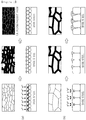
- FIGS. 3A and 3B are schematic views showing the corrosion processes of plated steel materials.
- FIG. 3 (a) is a schematic view shown the case in which grains are relatively fine
- FIG. 3 (b) is a schematic view illustrating the case in which grains are relatively coarse. Referring to FIGS. 3A and 3B , it could be understood that that when the size of grains is small, relatively dense and uniform corrosion products are formed while corrosion occurs, and thus corrosion may be delayed by the dense and uniform corrosion products.
- the average grain diameter of the multiple plating layers also has a significant effect on the spot weldability of the plated steel material.
- the average grain diameter is equal to or less than a certain value, the formation of type B cracks is remarkably reduced, and the reason for this may be that the migration of atoms in a molten plating layer actively occurs and thus the formation of an intended microstructure is facilitated.
- the average grain diameter of the multiple plating layers may be preferably adjusted to be 100 nm or less (excluding 0 nm).
- the average grain diameter refers to the average long diameter of grains measured by observing thicknesswise cross-sections of the multiple plating layers.
- the sum of plating amounts of the multiple plating layers may be within the range of 40 g/m 2 or less (excluding 0 g/m 2 ). As the sum of plating amounts of the multiple plating layers increases, corrosion resistance may increase but liquid metal embrittlement (LME) may occur during spot welding, and thus the upper limit of the sum of plating amounts may be adjusted as described above. In addition, considering both the corrosion resistance and the spot weldability, the sum of plating amounts of the multiple plating layers may be adjusted to be preferably within the range of 10 g/m 2 to 35 g/m 2 , and more preferably within the range of 15 g/m 2 to 30 g/m 2 .
- LME liquid metal embrittlement
- the zinc alloy plated steel material of the present disclosure is characterized by including two or more plating layers to improve corrosion resistance and weldability as described above, and platability and phosphate treatment properties as well.
- plating layers to improve corrosion resistance and weldability as described above, and platability and phosphate treatment properties as well.
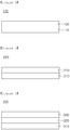
- FIG. 4 is a schematic diagram illustrating a multilayer zinc alloy plated steel material 100 according to an embodiment of the present disclosure.
- multiple plating layers may include a first plating layer 110 formed on a base steel material and a second plating layer 120 formed on the first plating layer 110, wherein the first plating layer 110 may include a Zn single phase or a Zn single phase and a Zn-Mg alloy phase and may have a Mg content within the range of 7 wt% or less, and the second plating layer 120 may include a Zn-Mg alloy phase.
- each of the multiple plating layers may further include an additional alloy phase in addition to the Zn single phase and the Zn-Mg alloy phase.
- a Zn-Mg alloy phase such as a Mg 2 Zn 11 alloy phase, a MgZn 2 alloy phase, a MgZn alloy phase, or a Mg 7 Zn 3 alloy phase is an intermetallic compound which not only has high hardness but also high brittleness, thereby lowering platability and causing separation of a plating layer when a zinc alloy plated steel material is formed.
- the present inventors have tried to impart ductility to the first plating layer 110 formed adjacent to the base steel material in order to compensate for the increase in the brittleness of the plating layers due to the formation of the Zn-Mg alloy phase, and have found, as one method for this, that when the first plating layer 110 is a Zn plating layer or a Zn-Mg alloy plating layer having a Mg content of 7 wt% or less (preferably, 6.3 wt% or less, and more preferably 5.5 wt% or less), plating adhesion may be significantly improved.
- the first plating layer 110 may have a composite phase including a Zn single phase and a Mg 2 Zn 11 alloy phase, and in this case, the first plating layer 110 may include the Zn single phase in an area fraction of 20% or greater.
- the first plating layer 110 may have high compressive strength such that the first plating layer 110 may absorb and buffer stress during forming and may thus result in high platability.
- the plating amount of the first plating layer 110 may be 3 g/m 2 or greater. In the present embodiment, platability may be sufficiently improved as intended by controlling the plating amount of the first plating layer 110 as described above. In an embodiment of the present disclosure, the plating amount of 3 g/m 2 may correspond to a thickness of 0.6 ⁇ m.
- FIG. 5 is a schematic diagram illustrating a multilayer zinc alloy plated steel material 200 according to another embodiment of the present disclosure.
- multiple plating layers may include a first plating layer 210 formed on a base steel material and a second plating layer 220 formed on the first plating layer 210, wherein the first plating layer 210 may include a Zn-Mg alloy phase and the second plating layer 220 may include a Zn single phase or a Zn single phase and a Zn-Mg alloy phase and may have a Mg content within the range of 2 wt% or less.
- each of the multiple plating layers may further include an additional alloy phase in addition to the Zn single phase and the Zn-Mg alloy phase.
- the phosphate treatment properties of the zinc alloy plated steel material may deteriorate.
- the reason for this is that the corrosion potential difference between the Zn-Mg alloy phase and Ni ions included in a phosphate treatment solution causes galvanic corrosion and thus promotes the dissolution of the plating layers, and as a result, pits exposing the base steel material are formed.
- the second plating layer 220 located on the outermost surface of the zinc alloy plated steel material 200 may be controlled to include only the Zn single phase, or the fraction of the Zn-Mg alloy phase of the second plating layer 220 may be adjusted to be a certain value or less, so as to effectively improve the phosphate treatment properties of the zinc alloy plated steel material 200.
- the plating amount of the second plating layer 220 may be 2 g/m 2 or greater.
- phosphate treatment properties may be sufficiently improved as intended by controlling the plating amount of the second plating layer 220 as described above.
- FIG. 6 is a schematic diagram illustrating a multilayer zinc alloy plated steel material 300 according to another embodiment of the present disclosure.
- multiple plating layers may include first to third plating layers 310, 320, and 330 sequentially formed on a base steel material, wherein the first plating layer 310 may include a Zn single phase or a Zn single phase and a Zn-Mg alloy phase and may have a Mg content within the range of 7 wt% or less, the second plating layer 320 may include a Zn-Mg alloy phase, and the third plating layer 330 may include a Zn single phase or a Zn single phase and a Zn-Mg alloy phase and may have a Mg content within the range of 2 wt% or less.
- each of the multiple plating layers may further include an additional alloy phase in addition to the Zn single phase and the Zn-Mg alloy phase.
- the zinc alloy plated steel material 300 sequentially includes the first to third plating layers 310, 320 and 330, the corrosion resistance, the spot weldability, the platability, and the phosphate treatment properties of the zinc alloy plated steel material 300.
- the first plating layer 310 may have a composite phase including a Zn single phase and a Mg 2 Zn 11 alloy phase, and in this case, the first plating layer 310 may include the Zn single phase in an area fraction of 20% or greater.
- the first plating layer 310 may have high compressive strength such that the first plating layer 110 may absorb and buffer stress during machining and may thus result in high platability.
- the plating amount of the first plating layer 310 may be 3 g/m 2 or greater, and the plating amount of the third plating layer 330 may be 2 g/m 2 or greater.
- the zinc alloy plated steel material may have the same features as that of the multilayer zinc alloy plated steel materials of the previous embodiments which are common in this embodiment.
- the zinc alloy plated steel materials of the present disclosure may be manufactured by various methods without limitations. For example, according to an embodiment, the following manufacturing method may be used.
- a base steel material may be prepared, and a pickling process using an aqueous solution having HCl in an amount of 14 wt% or greater, a rinsing process, and a drying process may performed on the base steel material. Then, foreign substances and a natural oxide film may be removed from the surface of the base steel material by using plasma, ion beams, or the like. Next, the zinc alloy plated steel material can be obtained by forming multiple plating layers sequentially on the base steel material.
- each of the multiple plating layers may be formed by an electroplating method or a general vacuum deposition method such as an electron beam method, a sputtering method, a thermal evaporation method, an induction heating evaporation method, an ion plating method.
- a Mg plating layer or a Zn-Mg alloy plating layer may be formed by an electromagnetic levitation physical vapor deposition method having an electromagnetic stirring effect.
- electromagnetic levitation physical vapor deposition refers to a method using a phenomenon in which if electromagnetic force is generated by applying high frequency power to a pair of electromagnetic coils generating an alternating electromagnetic field, a coating material (Zn, Mg or a Zn-Mg alloy in the present disclosure) is levitated in a space surround by the electromagnetic field without external help, and the levitated coating material produces a large amount of deposition vapor (metal vapor).
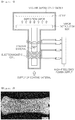
- FIG. 7 is a schematic view illustrating an apparatus for such electromagnetic levitation physical vapor deposition. Referring to FIG. 7 , a large amount of deposited vapor formed by the above-described method is sprayed onto the surface of a base steel material through a plurality of nozzles of a vapor distribution box at high speed, thereby forming a plating layer.
- a coating material is provided in a crucible, and the coating material is vaporized by heating the crucible.
- the coating material is vaporized by heating the crucible.
- it is difficult to supply sufficient thermal energy to the coating material because of melting of the crucible and thermal loss at the crucible. This decreases the rate of deposition and limits grain refinement of a plating layer.
- deposition when deposition is performed by the electromagnetic levitation physical vapor deposition method, there are no temperature limitations unlike in a general vacuum deposition method, and thus the coating material may be exposed to a higher temperature environment. Therefore, deposition may be performed at a high rate, and thus a plating layer having fine grains and uniformly distributed alloying elements may be formed.
- the degree of vacuum inside a vacuum deposition chamber may be preferably adjusted to be within the range of 1.0 ⁇ 10 -3 mbar to 1.0 ⁇ 10 -5 mbar, and in this case, an increase in brittleness and deterioration of material properties may be effectively prevented when a plating layer is formed.
- the temperature of the levitated coating material may be adjusted to be 700°C or greater, more preferably 800°C or greater, and even more preferably 1000°C or greater. If the temperature of the levitated coating material is less than 700°C, grain refinement and plating layer uniformity may not be sufficiently guaranteed. In addition, as the temperature of the levitated coating material increases, intended technical effects may be easily obtained, and thus the upper limit of the temperature of the levitated coating material is not limited to a particular value in the present disclosure. However, if the temperature is higher than a certain value, such effects are saturated, and processing costs increase excessively. Thus, the upper limit of the temperature may be set to be 1500°C.
- the temperature of the base steel material may be adjusted to be 100°C or less before and after the deposition process. If the temperature of the base steel material exceeds 100°C, the temperature of the base steel material may not be uniform in the width direction thereof, and thus the base steel material may have a radius curve in the width direction thereof, making it difficult to maintain the degree of vacuum when the base steel material passes through a multistage differential pressure reducing system at an exit side.
- High-strength cold rolled steel sheets for automobiles having a thickness of 1.4 mm and including, by wt%, C: 0.16%, Si: 1.43%, Mn: 2.56%, Al: 0.04%, P: 0.006%, S: 0.0029%, and the balance of Fe and inevitable impurities, were prepared, and multilayer zinc alloy plated steel materials including multiple plating layers having compositions as shown in Table 1 below were fabricated from the prepared high-strength cold rolled steel sheets by using the apparatus shown in FIG. 7 (vacuum degree: 3.2 ⁇ 10 -3 mbar).
- each plating layer was formed through a separate process using a separate vacuum chamber, and when each plating layer was formed, a current of 1.2 kA was applied to a pair of electromagnetic coils, a frequency applied to the pair of electromagnetic coils was adjusted to be 60 kHz based on 2 kg of a deposition material, the temperature of a levitated coating material was set to 1000°C, and the temperature of the vapor distribution box was constantly maintained at 900°C. In addition, the temperature of the base steel was constantly maintained at 60° C before and after each plating layer was deposited.
- the plating amount and the Mg weight ratio of each multilayer zinc alloy plated steel material were measured using an inductively coupled plasma (ICP) method. More specifically, a specimen having a size of 80 mm x 80 mm was cut out, the surface of the specimen was degreased, and then, the weight of the specimen was primarily measured using a high-precision scale (primary weight W 1 : 0.0000 g). Thereafter, the front side of the specimen was attached to a column for an 54.5 mm diameter O-ring by using a clamp and was tightened to prevent leakage of a solution. Then, 30 cc of a 1:3 HCl solution was added, and two or three drops of an inhibitor were added.
- ICP inductively coupled plasma
- the solution was collected in a 100-cc mass flask. At that time, all the remaining solution was collected using a cleaning bottle in an amount of 100 cc or less. Thereafter, the specimen was completely dried, the weight of the specimen was measured (secondary weight W 2 ), and the value obtained by dividing the difference between the primary weight W 1 and the secondary weight W 2 by a unit area was taken as a total plating amount. In addition, the content of Mg was measured using the collected solution by an ICP method as a Mg weight ratio.
- specimens having a size of 40 mm x 120 mm were prepared by cutting, and the formation of type B cracks and the size of type B cracks were measured after performing a spot welding process on each specimen 100 times. Then, weldability was evaluated according to the following criteria.
- Corrosion resistance was evaluated by cutting specimens having a size of 75 mm x 150 mm out of the multilayer zinc alloy plated steel materials, performing a salt spray test on the specimens by JIS Z2371 to measure times of the occurrence of initial red rust, and performing evaluation according to the following criteria.
- Powdering resistance was evaluated by cutting specimens having a size of 40 mm x 80 mm out of the multilayer zinc alloy plated steel materials, setting the specimens to a press tester, performing a 60° bending test on the specimens, detaching the specimens from the tester, attaching cellophane tape to bent portions of the specimens, separating the cellophane tape, attaching the separated cellophane tape to white paper to measure peeled-off widths, and performing evaluation according to the following criteria.
- Phosphate treatment properties were evaluated by cutting specimens having a size of 75 mm x 150 mm out of the multilayer zinc alloy plated steel materials, performing surface adjustment and phosphate treatment according to general specifications of automobile company, and evaluating the uniformity of phosphate.
- Inventive Examples 1 to 20 satisfying all the conditions proposed in the present disclosure had high corrosion resistance and spot weldability.
- the Mg weight ratio is within the range of 0.157 to 0.20 and the sum of plating amounts of the multiple plating layers be within the range of 35 g/m2 or less, so as to further improve spot weldability.
- Comparative Examples 1 to 8 had a Mg weight ratio outside the range proposed in the present disclosure, the spot weldability of Comparative Samples 1 to 8 was poor.
- FIG. 8 is an image showing a weld zone formed by a spot welding in a multilayer zinc alloy plated steel material of Inventive Sample 18. Referring to FIG. 8 , it could be visually checked that the multiple plating layers of the multilayer zinc alloy plated steel material of the present disclosure was changed to a single alloy layer after welding, the single alloy layer in the weld zone had a MgZn 2 alloy phase in an area fraction of 90% or greater, and type B cracks and type C were not formed in the weld zone.
Landscapes
- Chemical & Material Sciences (AREA)
- Engineering & Computer Science (AREA)
- Materials Engineering (AREA)
- Mechanical Engineering (AREA)
- Metallurgy (AREA)
- Organic Chemistry (AREA)
- Chemical Kinetics & Catalysis (AREA)
- Inorganic Chemistry (AREA)
- Coating With Molten Metal (AREA)
- Other Surface Treatments For Metallic Materials (AREA)
- Physics & Mathematics (AREA)
- Oil, Petroleum & Natural Gas (AREA)
- Thermal Sciences (AREA)
- Electroplating Methods And Accessories (AREA)
- Physical Vapour Deposition (AREA)
Abstract
Description
- The present disclosure relates to a multilayer zinc alloy plated steel material having excellent spot weldability and corrosion resistance, and more particularly, to a multilayer zinc alloy plated steel material having excellent spot weldability and corrosion resistance and (being) applicable to automobiles, home appliances, and construction, etc.
- Zinc plating methods for suppressing the corrosion of iron by cathodic protection provide high corrosion resistance and economical efficiency and are thus widely used for manufacturing steel materials having high corrosion resistance, and there has been increasing demand for zinc plated steel materials in industrial fields such as automobiles, home appliances, constructions.
- When a zinc plated steel material is exposed to a corrosive environment, zinc having a lower oxidation-reduction potential than iron undergoes corrosion first, and thus corrosion of the steel material is suppressed by sacrificial corrosion protection. Along with this, dense corrosion products are formed on the surface of the steel material while zinc of the plating layer is oxidized, thereby protecting the steel material from the corrosive environment and improving the corrosion resistance of the steel material.
- However, air pollution and corrosive environments have increased with industrial advances, and regulations on resources and energy savings have been tightened. Therefore, the need to develop steel materials having higher corrosion resistance than existing zinc plated steel materials has increased. To this end, various studies have been conducted on the technology for manufacturing zinc alloy plated steel materials which have improved corrosion resistance by the addition of elements such as magnesium (Mg) to plating layers.
- In general, zinc plated steel materials or zinc alloy plated steel materials (hereinafter, referred to as "zinc plated steel materials") are used as products after being processed into parts through forming process etc. and being welded through welding processes such as a spot welding process. In the case of zinc plated steel materials having base steel materials such as high-strength steel materials having austenite or retained austenite as a microstructure or high-strength interstitial free (IF) steel materials having a high phosphorus (P) content, molten zinc permeate into the base steel materials along grain boundaries during a spot welding process, causing brittle cracks, that is, liquid metal embrittlement (LME).
-
FIG. 1 is an enlarged image showing a weld zone of welded members in which LME cracking occurred as a result of spot welding. InFIG. 1 , cracks formed in the upper and lower portions of a nugget are referred to as type A cracks, a crack formed in a weld shoulder portion is referred to a type B cracks, and a cracks formed inside a steel sheet because of misalignment of electrodes during welding is referred to as a type C cracks. Among such cracks, type B and C cracks greatly affect the soundness of materials, and it is a key requirement in the art to prevent the formation of cracks during welding. - An aspect of the present disclosure may provide a multilayer zinc alloy plated steel material having high spot weldability and corrosion resistance.
- According to an aspect of the present disclosure, a multilayer zinc alloy plated steel material may include a base steel material and multiple plating layers formed on the base steel material, wherein each of the multiple plating layers may include one of a Zn plating layer, a Mg plating layer, and a Zn-Mg alloy plating layer, and the ratio of the weight of Mg contained in the multiple plating layers to the total weight of the multiple plating layers may be from 0.13 to 0.24.
- One of the effects of the present disclosure is that the multilayer zinc alloy plated steel material has high spot weldability, and thus even when a steel material such as a high-strength steel material including austenite or retained austenite as a microstructure, or a high-strength interstitial free (IF) steel material having a high phosphorus (P) content is used as a base steel material, the occurrence of liquid metal embrittlement (LME) may be effectively suppressed.
- In addition, the multilayer zinc alloy plated steel material of the present disclosure may have high corrosion resistance even though the plating amount thereof is low, and thus the multilayer zinc alloy plated steel material may be environmentally friendly and economical.
- In addition, according to embodiments of the present disclosure, the multilayer zinc alloy plated steel material may have high platability.
- In addition, according to embodiments of the present disclosure, the multilayer zinc alloy plated steel material may have improved phosphate treatment properties.
- Aspects and effects of the present disclosure are not limited thereto, and may be apparently understood through the descriptions of embodiments of the present disclosure.
-
-
FIG. 1 is an enlarged image showing a weld zone of welded members in which LME cracking occurred as a result of spot welding. -
FIG. 2 is a phase diagram of a Mg-Zn binary alloy system. -
FIGS. 3A and 3B are schematic views showing the corrosion processes of plated steel materials. -
FIG. 4 is a schematic diagram illustrating a multilayer zinc alloy platedsteel material 100 according to an embodiment of the present disclosure. -
FIG. 5 is a schematic diagram illustrating a multilayer zinc alloy platedsteel material 200 according to another embodiment of the present disclosure. -
FIG. 6 is a schematic diagram illustrating a multilayer zinc alloy platedsteel material 300 according to another embodiment of the present disclosure. -
FIG. 7 is a schematic diagram illustrating an electromagnetic levitation physical vapor deposition apparatus. -
FIG. 8 is an image showing a weld zone formed by a spot welding in a multilayer zinc alloy plated steel material of Inventive Sample 18. - It is known that as the content of Mg increases in Zn-Mg alloy plated steels, the Zn-Mg alloy plated steels increase in corrosion resistance but decrease in spot weldability, and thus the maximum content of Mg in plating layers is generally adjusted to be about 10 wt%. The reason for this is that Zn-Mg intermetallic compounds having a low melting point easily dissolve in a Zn-Mg plating layer to cause liquid metal embrittlement. However, additional studies of the present inventors have showed that even if the content of Mg in a plating layer exceeds 10 wt%, spot weldability is markedly improved in a certain Mg content range. In particular, this spot weldability improving effect is obtainable in the case of forming two or more plating layers as well as in the case of forming a single plating layer, and based on this, the present inventors have found that additional effects such as improvements in platability and phosphate treatment properties are also obtainable and have invented the present invention.
- Hereinafter, a zinc alloy plated steel material having high spot weldability and corrosion resistance will be described in detail. In the present disclosure, the upper and lower sides of a steel sheet may be reversed at any time depending on the state of stacking, and thus the expression "on" such as "on a base steel material" merely refers to the state of contact but does not refers to or imply the state of being located on an upper side."
- The zinc alloy plated steel material of the present disclosure includes a base steel material and multiple plating layers formed on the base steel material. In the present disclosure, the base steel material is not limited to particular types. For example, the base steel material may be a steel sheet or a steel wire rod.
- Furthermore, in the present disclosure, the composition of the base steel material is not particularly limited. For example, the base steel may include, by wt%, C: 0.10% to 1.0%, Si: 0.5% to 3%, Mn: 1.0% to 25%, Al: 0.01% to 10%, P: 0.1% or less (excluding 0%), S: 0.01% or less (excluding 0%), and the balance of Fe and inevitable impurities, and the contents of C, Si, Mn, P, and S contained in the base steel material may satisfy Condition 1 below. In addition, the base steel material having the above-described composition may include austenite or retained austenite as a microstructure.

- In the case that the base steel has above-described composition and microstructure, liquid metal embrittlement (LME) may be a major problem for the following reasons. That is, austenite or retained austenite has weaker grain boundaries than other phases, and thus when stress is applied thereto during spot welding, molten zinc may penetrate into the grain boundaries of austenite or retained austenite in a weld zone to cause cracks, that is, brittle fracture by liquid metal embrittlement (LME).
- However, according to the present disclosure, as described later, the time during which molten zinc remains is minimized, and thus the occurrence of liquid metal embrittlement (LME) may be effectively suppressed even if a zinc alloy plated steel material is manufactured using a steel material having the above-described composition and microstructure as a base steel material. In addition, the idea of the present disclosure may even be applied to a base steel material that does not satisfy the above-described composition.
- Each of the multiple plating layers is one of a Zn plating layer, a Mg plating layer, and a Zn-Mg alloy plating layer, and the present disclosure has a technical feature in which the ratio of the weight of Mg contained in the multiple plating layers to the total weight of the multiple plating layers is from 0.13 to 0.24. More preferably, the Mg weight ratio may be within the range of 0.157 to 0.20.
- The Zn-Mg alloy plating layer may have a microstructure comprising a Zn single phase, a Mg single phase, a Mg2Zn11 alloy phase, a MgZn2 alloy phase, a MgZn alloy phase, a Mg7Zn3 alloy phase, or the like, and the present inventors have found that if the content of Mg contained in the multiple plating layers is adjusted within the above-mentioned range, the multiple plating layers are melted and changed to a single alloy layer including a MgZn2 alloy phase in an area fraction of 90% or greater (including 100%) in a weld zone during spot welding, and thus liquid metal embrittlement (LME) is effectively suppressed. The reason for this may be that, as shown in the phase diagram of a Mg-Zn binary alloy system in
FIG. 2 , the melting point of the single alloy layer is high, and thus the time during which the single alloy layer remains in a liquid state is minimized. Furthermore, in the present disclosure, other microstructures than the MgZn2 alloy phase in the single alloy layer are not particularly limited. In a non-limiting example, the single alloy layer may include a Mg2Zn11 alloy phase as a remainder in addition to the MgZn2 alloy phase. - Here, phase fractions may be measured and analyzed by a standard Rietveld quantitative analysis method using an XRD and a more accurate TEM-based crystal orientation mapping technique (TEM-ASTAR) as well, but the present disclosure is not limited thereto. In addition, the phase transformation process of the Zn-Mg alloy plating layer may be analyzed using high-temperature in-situ synchrotron XRD. More specifically, the phase transformation process of the Zn-Mg alloy plating layer may be analyzed by heating specimens to 780°C at heating rates of 1.3°C/sec and 11.3°C/sec and measuring XRD spectra at a frame rate of 1 second, totally consecutive 900 frames during a heating and cooling thermal cycle. However, this is a non-limiting example.
- According to an additional study conducted by the present inventors, although the content of Mg is adjusted to be within the above-described range, it may be difficult to improve spot weldability if the content of Mg excessively deviates in the width direction of the plating layers (a direction perpendicular to the direction of rolling). Thus, it may be required to appropriately control the upper limit of the deviation of the Mg content in the width direction of the multiple plating layers, and preferably, the deviation of the Mg content may be controlled to be within ± 5% when a GDS profile is measured in a thicknesswise center portion of each of the multiple plating layers.
- According to an additional study conducted by the present inventors, the average grain diameter of the multiple plating layers has a significant effect on the corrosion resistance of the plated steel material.
FIGS. 3A and 3B are schematic views showing the corrosion processes of plated steel materials.FIG. 3 (a) is a schematic view shown the case in which grains are relatively fine, andFIG. 3 (b) is a schematic view illustrating the case in which grains are relatively coarse. Referring toFIGS. 3A and 3B , it could be understood that that when the size of grains is small, relatively dense and uniform corrosion products are formed while corrosion occurs, and thus corrosion may be delayed by the dense and uniform corrosion products. - In addition, the average grain diameter of the multiple plating layers also has a significant effect on the spot weldability of the plated steel material. When the average grain diameter is equal to or less than a certain value, the formation of type B cracks is remarkably reduced, and the reason for this may be that the migration of atoms in a molten plating layer actively occurs and thus the formation of an intended microstructure is facilitated.
- Thus, considering the corrosion resistance and spot weldability of the plated steel, it may be required to appropriately adjust the upper limit of the average grain diameter of the multiple plating layers, and the average grain diameter of the multiple plating layers may be preferably adjusted to be 100 nm or less (excluding 0 nm). Here, the average grain diameter refers to the average long diameter of grains measured by observing thicknesswise cross-sections of the multiple plating layers.
- According to an example of the present disclosure, the sum of plating amounts of the multiple plating layers may be within the range of 40 g/m2 or less (excluding 0 g/m2). As the sum of plating amounts of the multiple plating layers increases, corrosion resistance may increase but liquid metal embrittlement (LME) may occur during spot welding, and thus the upper limit of the sum of plating amounts may be adjusted as described above. In addition, considering both the corrosion resistance and the spot weldability, the sum of plating amounts of the multiple plating layers may be adjusted to be preferably within the range of 10 g/m2 to 35 g/m2, and more preferably within the range of 15 g/m2 to 30 g/m2.
- In addition, as described above, the zinc alloy plated steel material of the present disclosure is characterized by including two or more plating layers to improve corrosion resistance and weldability as described above, and platability and phosphate treatment properties as well. Hereinafter, this will be described in detail with specific embodiments.
-
FIG. 4 is a schematic diagram illustrating a multilayer zinc alloy platedsteel material 100 according to an embodiment of the present disclosure. - According to the embodiment of the present disclosure, multiple plating layers may include a
first plating layer 110 formed on a base steel material and asecond plating layer 120 formed on thefirst plating layer 110, wherein thefirst plating layer 110 may include a Zn single phase or a Zn single phase and a Zn-Mg alloy phase and may have a Mg content within the range of 7 wt% or less, and thesecond plating layer 120 may include a Zn-Mg alloy phase. In this case, each of the multiple plating layers may further include an additional alloy phase in addition to the Zn single phase and the Zn-Mg alloy phase. - A Zn-Mg alloy phase such as a Mg2Zn11 alloy phase, a MgZn2 alloy phase, a MgZn alloy phase, or a Mg7Zn3 alloy phase is an intermetallic compound which not only has high hardness but also high brittleness, thereby lowering platability and causing separation of a plating layer when a zinc alloy plated steel material is formed. Accordingly, the present inventors have tried to impart ductility to the
first plating layer 110 formed adjacent to the base steel material in order to compensate for the increase in the brittleness of the plating layers due to the formation of the Zn-Mg alloy phase, and have found, as one method for this, that when thefirst plating layer 110 is a Zn plating layer or a Zn-Mg alloy plating layer having a Mg content of 7 wt% or less (preferably, 6.3 wt% or less, and more preferably 5.5 wt% or less), plating adhesion may be significantly improved. - For example, the
first plating layer 110 may have a composite phase including a Zn single phase and a Mg2Zn11 alloy phase, and in this case, thefirst plating layer 110 may include the Zn single phase in an area fraction of 20% or greater. When thefirst plating layer 110 has the above-described microstructure, thefirst plating layer 110 may have high compressive strength such that thefirst plating layer 110 may absorb and buffer stress during forming and may thus result in high platability. - According to an example of the present disclosure, the plating amount of the
first plating layer 110 may be 3 g/m2 or greater. In the present embodiment, platability may be sufficiently improved as intended by controlling the plating amount of thefirst plating layer 110 as described above. In an embodiment of the present disclosure, the plating amount of 3 g/m2 may correspond to a thickness of 0.6 µm. -
FIG. 5 is a schematic diagram illustrating a multilayer zinc alloy platedsteel material 200 according to another embodiment of the present disclosure. - In an embodiment of the present disclosure, multiple plating layers may include a
first plating layer 210 formed on a base steel material and asecond plating layer 220 formed on thefirst plating layer 210, wherein thefirst plating layer 210 may include a Zn-Mg alloy phase and thesecond plating layer 220 may include a Zn single phase or a Zn single phase and a Zn-Mg alloy phase and may have a Mg content within the range of 2 wt% or less. In this case, each of the multiple plating layers may further include an additional alloy phase in addition to the Zn single phase and the Zn-Mg alloy phase. - If the outermost surface of the zinc alloy plated
steel material 200 includes the Zn-Mg phase in a certain amount or greater, the phosphate treatment properties of the zinc alloy plated steel material may deteriorate. The reason for this is that the corrosion potential difference between the Zn-Mg alloy phase and Ni ions included in a phosphate treatment solution causes galvanic corrosion and thus promotes the dissolution of the plating layers, and as a result, pits exposing the base steel material are formed. Considering this, thesecond plating layer 220 located on the outermost surface of the zinc alloy platedsteel material 200 may be controlled to include only the Zn single phase, or the fraction of the Zn-Mg alloy phase of thesecond plating layer 220 may be adjusted to be a certain value or less, so as to effectively improve the phosphate treatment properties of the zinc alloy platedsteel material 200. - For example, the plating amount of the
second plating layer 220 may be 2 g/m2 or greater. In the present embodiment, phosphate treatment properties may be sufficiently improved as intended by controlling the plating amount of thesecond plating layer 220 as described above. -
FIG. 6 is a schematic diagram illustrating a multilayer zinc alloy platedsteel material 300 according to another embodiment of the present disclosure. - According to an embodiment of the present disclosure, multiple plating layers may include first to third plating layers 310, 320, and 330 sequentially formed on a base steel material, wherein the
first plating layer 310 may include a Zn single phase or a Zn single phase and a Zn-Mg alloy phase and may have a Mg content within the range of 7 wt% or less, thesecond plating layer 320 may include a Zn-Mg alloy phase, and thethird plating layer 330 may include a Zn single phase or a Zn single phase and a Zn-Mg alloy phase and may have a Mg content within the range of 2 wt% or less. In this case, each of the multiple plating layers may further include an additional alloy phase in addition to the Zn single phase and the Zn-Mg alloy phase. - When the zinc alloy plated
steel material 300 sequentially includes the first to third plating layers 310, 320 and 330, the corrosion resistance, the spot weldability, the platability, and the phosphate treatment properties of the zinc alloy platedsteel material 300. - The
first plating layer 310 may have a composite phase including a Zn single phase and a Mg2Zn11 alloy phase, and in this case, thefirst plating layer 310 may include the Zn single phase in an area fraction of 20% or greater. When thefirst plating layer 310 has the above-described microstructure, thefirst plating layer 310 may have high compressive strength such that thefirst plating layer 110 may absorb and buffer stress during machining and may thus result in high platability. - In this case, the plating amount of the
first plating layer 310 may be 3 g/m2 or greater, and the plating amount of thethird plating layer 330 may be 2 g/m2 or greater. - Except that the multiple plating layers include the first to three layers, the zinc alloy plated steel material may have the same features as that of the multilayer zinc alloy plated steel materials of the previous embodiments which are common in this embodiment.
- The zinc alloy plated steel materials of the present disclosure may be manufactured by various methods without limitations. For example, according to an embodiment, the following manufacturing method may be used.
- First, a base steel material may be prepared, and a pickling process using an aqueous solution having HCl in an amount of 14 wt% or greater, a rinsing process, and a drying process may performed on the base steel material. Then, foreign substances and a natural oxide film may be removed from the surface of the base steel material by using plasma, ion beams, or the like. Next, the zinc alloy plated steel material can be obtained by forming multiple plating layers sequentially on the base steel material.
- At this time, each of the multiple plating layers may be formed by an electroplating method or a general vacuum deposition method such as an electron beam method, a sputtering method, a thermal evaporation method, an induction heating evaporation method, an ion plating method. However, a Mg plating layer or a Zn-Mg alloy plating layer may be formed by an electromagnetic levitation physical vapor deposition method having an electromagnetic stirring effect.
- Here, the term "electromagnetic levitation physical vapor deposition" refers to a method using a phenomenon in which if electromagnetic force is generated by applying high frequency power to a pair of electromagnetic coils generating an alternating electromagnetic field, a coating material (Zn, Mg or a Zn-Mg alloy in the present disclosure) is levitated in a space surround by the electromagnetic field without external help, and the levitated coating material produces a large amount of deposition vapor (metal vapor).
FIG. 7 is a schematic view illustrating an apparatus for such electromagnetic levitation physical vapor deposition. Referring toFIG. 7 , a large amount of deposited vapor formed by the above-described method is sprayed onto the surface of a base steel material through a plurality of nozzles of a vapor distribution box at high speed, thereby forming a plating layer. - In a general vacuum vapor deposition apparatus, a coating material is provided in a crucible, and the coating material is vaporized by heating the crucible. In this case, it is difficult to supply sufficient thermal energy to the coating material because of melting of the crucible and thermal loss at the crucible. This decreases the rate of deposition and limits grain refinement of a plating layer. In addition, there is a limit to the uniformity of a plating layer when a Zn-Mg alloy vapor is deposited as is in the present disclosure.
- However, when deposition is performed by the electromagnetic levitation physical vapor deposition method, there are no temperature limitations unlike in a general vacuum deposition method, and thus the coating material may be exposed to a higher temperature environment. Therefore, deposition may be performed at a high rate, and thus a plating layer having fine grains and uniformly distributed alloying elements may be formed.
- During a deposition process, the degree of vacuum inside a vacuum deposition chamber may be preferably adjusted to be within the range of 1.0 × 10⁻³ mbar to 1.0 × 10⁻⁵ mbar, and in this case, an increase in brittleness and deterioration of material properties may be effectively prevented when a plating layer is formed.
- In the deposition process, preferably, the temperature of the levitated coating material may be adjusted to be 700°C or greater, more preferably 800°C or greater, and even more preferably 1000°C or greater. If the temperature of the levitated coating material is less than 700°C, grain refinement and plating layer uniformity may not be sufficiently guaranteed. In addition, as the temperature of the levitated coating material increases, intended technical effects may be easily obtained, and thus the upper limit of the temperature of the levitated coating material is not limited to a particular value in the present disclosure. However, if the temperature is higher than a certain value, such effects are saturated, and processing costs increase excessively. Thus, the upper limit of the temperature may be set to be 1500°C.
- Preferably, the temperature of the base steel material may be adjusted to be 100°C or less before and after the deposition process. If the temperature of the base steel material exceeds 100°C, the temperature of the base steel material may not be uniform in the width direction thereof, and thus the base steel material may have a radius curve in the width direction thereof, making it difficult to maintain the degree of vacuum when the base steel material passes through a multistage differential pressure reducing system at an exit side.
- Hereinafter, the present disclosure will be described more specifically through examples. However, the following examples are for illustrative purposes only and are not intended to limit the scope of the present disclosure. The scope of the present invention is defined by the appended claims, and modifications and variations reasonably made therefrom.
- High-strength cold rolled steel sheets for automobiles, having a thickness of 1.4 mm and including, by wt%, C: 0.16%, Si: 1.43%, Mn: 2.56%, Al: 0.04%, P: 0.006%, S: 0.0029%, and the balance of Fe and inevitable impurities, were prepared, and multilayer zinc alloy plated steel materials including multiple plating layers having compositions as shown in Table 1 below were fabricated from the prepared high-strength cold rolled steel sheets by using the apparatus shown in
FIG. 7 (vacuum degree: 3.2 × 10⁻³ mbar). In each example, each plating layer was formed through a separate process using a separate vacuum chamber, and when each plating layer was formed, a current of 1.2 kA was applied to a pair of electromagnetic coils, a frequency applied to the pair of electromagnetic coils was adjusted to be 60 kHz based on 2 kg of a deposition material, the temperature of a levitated coating material was set to 1000°C, and the temperature of the vapor distribution box was constantly maintained at 900°C. In addition, the temperature of the base steel was constantly maintained at 60° C before and after each plating layer was deposited. - Next, the plating amount and the Mg weight ratio of each multilayer zinc alloy plated steel material were measured using an inductively coupled plasma (ICP) method. More specifically, a specimen having a size of 80 mm x 80 mm was cut out, the surface of the specimen was degreased, and then, the weight of the specimen was primarily measured using a high-precision scale (primary weight W1 : 0.0000 g). Thereafter, the front side of the specimen was attached to a column for an 54.5 mm diameter O-ring by using a clamp and was tightened to prevent leakage of a solution. Then, 30 cc of a 1:3 HCl solution was added, and two or three drops of an inhibitor were added. After the generation of H2 gas on a surface, the solution was collected in a 100-cc mass flask. At that time, all the remaining solution was collected using a cleaning bottle in an amount of 100 cc or less. Thereafter, the specimen was completely dried, the weight of the specimen was measured (secondary weight W2), and the value obtained by dividing the difference between the primary weight W1 and the secondary weight W2 by a unit area was taken as a total plating amount. In addition, the content of Mg was measured using the collected solution by an ICP method as a Mg weight ratio.
- Next, a GDS profile was measured at a thicknesswise center portion of each of the multiple plating layers, and the average grain diameter of the multiple plating layers was measured. Results of measurement showed that the content of Mg deviated within the range of ± 5% and the average particle diameter was 100 µm or less in all the examples.
- Next, the weldability, corrosion resistance, powdering resistance, and phosphate treatment properties of each multilayer zinc alloy plated steel material were evaluated, and Table 2 below shows results thereof.
- More specifically, according to SEP 1220-2, specimens having a size of 40 mm x 120 mm were prepared by cutting, and the formation of type B cracks and the size of type B cracks were measured after performing a spot welding process on each
specimen 100 times. Then, weldability was evaluated according to the following criteria. - 1. Very good: no type B cracks were formed in all specimens.
- 2. Good: type B cracks were formed in some or all specimens, and the average length of the type B cracks was equal to or less than 0.1 times the thickness of the base steel material (cold rolled steel sheet).
- 3. Normal: type B cracks were formed in some or all specimens, and the average length of the type B cracks was greater than 0.1 times the thickness of the base steel material (cold rolled steel sheet) but equal to or less than 0.2 times the thickness of the base steel material.
- 4. Poor: type B cracks were formed in some or all specimens, and the average length of the type B cracks was greater than 0.2 times the thickness of the base steel material (cold rolled steel sheet).
- Corrosion resistance was evaluated by cutting specimens having a size of 75 mm x 150 mm out of the multilayer zinc alloy plated steel materials, performing a salt spray test on the specimens by JIS Z2371 to measure times of the occurrence of initial red rust, and performing evaluation according to the following criteria.
- 1. Good: the time period until the occurrence of red rust was equal to or greater than twice the red rust occurrence time period of a zinc plated steel sheet (GI steel sheet) having a plating amount of 60 g/m2 on one side.
- 2. Normal: the time period until the occurrence of red rust was similar to the red rust occurrence time period of a zinc plated steel sheet (GI steel sheet) having the plating amount of 60 g/m2 on one side, or less than twice the red rust occurrence time period of the zinc plated steel sheet (GI steel sheet).
- 3. Poor: the time period until the occurrence of red rust was less than the red rust occurrence time period of the zinc plated steel sheet (GI steel sheet) having a plating amount of 60 g/m2 on one side.
- Powdering resistance was evaluated by cutting specimens having a size of 40 mm x 80 mm out of the multilayer zinc alloy plated steel materials, setting the specimens to a press tester, performing a 60° bending test on the specimens, detaching the specimens from the tester, attaching cellophane tape to bent portions of the specimens, separating the cellophane tape, attaching the separated cellophane tape to white paper to measure peeled-off widths, and performing evaluation according to the following criteria.
- 1. Good: peeled-off width was 6.0 mm or less.
- 2. Normal: peeled-off width was greater than 6.0 mm but equal to or less 8.0 mm.
- 3. Poor: peeled-off width was greater than 8.0 mm.
- Phosphate treatment properties were evaluated by cutting specimens having a size of 75 mm x 150 mm out of the multilayer zinc alloy plated steel materials, performing surface adjustment and phosphate treatment according to general specifications of automobile company, and evaluating the uniformity of phosphate.
- 1. Good: phosphate film was uniformly formed.
- 2. Poor: phosphate film was not uniformly formed.
- Referring to Table 2, Inventive Examples 1 to 20 satisfying all the conditions proposed in the present disclosure had high corrosion resistance and spot weldability. In addition, it could be found that it is preferable that the Mg weight ratio is within the range of 0.157 to 0.20 and the sum of plating amounts of the multiple plating layers be within the range of 35 g/m2 or less, so as to further improve spot weldability.
- However, since Comparative Examples 1 to 8 had a Mg weight ratio outside the range proposed in the present disclosure, the spot weldability of Comparative Samples 1 to 8 was poor.
- In addition, referring to Table 2, it could be found that that when the lowest plating layer is a Zn plating layer or a Zn-Mg alloy plating layer having a Mg content preferably within the range of 7 wt% or less (excluding 0 wt%), platability can be improved, and when the uppermost plating layer is a Zn plating layer or a Zn-Mg alloy plating layer having a Mg content preferably within the range of 2 wt% or less (excluding 0 wt%), phosphate treatment properties can be improved.
-
FIG. 8 is an image showing a weld zone formed by a spot welding in a multilayer zinc alloy plated steel material of Inventive Sample 18. Referring toFIG. 8 , it could be visually checked that the multiple plating layers of the multilayer zinc alloy plated steel material of the present disclosure was changed to a single alloy layer after welding, the single alloy layer in the weld zone had a MgZn2 alloy phase in an area fraction of 90% or greater, and type B cracks and type C were not formed in the weld zone. -
- 100, 200, 300: MULTILAYER ZINC ALLOY PLATED STEEL MATERIALS
- 110, 210, 310: FIRST PLATING LAYERS
- 120, 220, 320: SECOND PLATING LAYERS
- 330: THIRD PLATING LAYER
| No. | First plating layer | Second plating layer | Third plating layer | Mg weight ratio | Note | |||
| Type (wt%) | Plating amount (g/m2) | Type (wt%) | Plating amount (g/m2) | Type (wt%) | Plating amount (g/m2) | |||
| 1 | Zn | 5 | Zn-Mg(16.5% Mg) | 15 | - | - | 0.124 | *CE1 |
| 2 | Zn | 5 | Zn-Mg(17.0% Mg) | 15 | - | - | 0.128 | CE2 |
| 3 | Zn | 5 | Zn-Mg(17.3% Mg) | 15 | - | - | 0.130 | **IE1 |
| 4 | Zn | 5 | Zn-Mg(18.7% Mg) | 15 | - | - | 0.140 | IE2 |
| 5 | Zn | 5 | Zn-Mg(20.7% Mg) | 15 | - | - | 0.155 | IE3 |
| 6 | Zn | 5 | Zn-Mg(21.0% Mg) | 15 | - | - | 0.158 | IE4 |
| 7 | Zn | 5 | Zn-Mg(22.0% Mg) | 15 | - | - | 0.165 | IE5 |
| 8 | Zn | 5 | Zn-Mg(24.0% Mg) | 15 | - | - | 0.180 | IE6 |
| 9 | Zn | 5 | Zn-Mg(26.0% Mg) | 15 | - | - | 0.195 | IE7 |
| 10 | Zn | 5 | Zn-Mg(27.3% Mg) | 15 | - | - | 0.205 | IE8 |
| 11 | Zn | 5 | Zn-Mg(29.3% Mg) | 15 | - | - | 0.220 | IE9 |
| 12 | Zn | 5 | Zn-Mg(32.0% Mg) | 15 | - | - | 0.240 | IE10 |
| 13 | Zn | 5 | Zn-Mg(32.3% Mg) | 15 | - | - | 0.242 | CE3 |
| 14 | Zn | 5 | Zn-Mg(32.6% Mg) | 15 | - | - | 0.245 | CE4 |
| 15 | Zn-Mg(5.0% Mg) | 5 | Zn-Mg(22.3% Mg) | 15 | - | - | 0.180 | IE11 |
| 16 | Zn-Mg(8.0% Mg) | 5 | Zn-Mg(21.3% Mg) | 15 | - | - | 0.180 | IE12 |
| 17 | Zn-Mg(15.0% Mg) | 17 | Zn | 3 | - | - | 0.128 | CE5 |
| 18 | Zn-Mg(17.0% Mg) | 17 | Zn | 3 | - | - | 0.145 | IE13 |
| 19 | Zn-Mg(21.2% Mg) | 17 | Zn | 3 | - | - | 0.180 | IE14 |
| 20 | Zn-Mg(25.9% Mg) | 17 | Zn | 3 | - | - | 0.220 | IE15 |
| 21 | Zn-Mg(28.5% Mg) | 17 | Zn | 3 | - | - | 0.242 | CE6 |
| 22 | Zn | 5 | Zn-Mg(20.8% Mg) | 12 | Zn | 3 | 0.125 | CE7 |
| 23 | Zn | 5 | Zn-Mg(27.5% Mg) | 12 | Zn | 3 | 0.165 | IE16 |
| 24 | Zn | 10 | Zn-Mg(27.5% Mg) | 24 | Zn | 6 | 0.165 | IE17 |
| 25 | Zn | 5 | Zn-Mg (30% Mg) | 12 | Zn | 3 | 0.180 | IE18 |
| 26 | Zn | 10 | Zn-Mg (30% Mg) | 24 | Zn | 6 | 0.180 | IE19 |
| 27 | Zn | 5 | Zn-Mg(36.6% Mg) | 12 | Zn | 3 | 0.220 | IE20 |
| 28 | Zn | 5 | Zn-Mg(40.8% Mg) | 12 | Zn | 3 | 0.245 | CE8 |
| *CE: Comparative Example, **IE: Inventive Example |
| No. | Weldability | Corrosion resistance | Powdering resistance | Phosphate treatment properties | Note |
| 1 | 4 | 1 | 1 | 2 | *CE1 |
| 2 | 3 | 1 | 1 | 2 | CE2 |
| 3 | 2 | 1 | 1 | 2 | **IE1 |
| 4 | 2 | 1 | 1 | 2 | IE2 |
| 5 | 2 | 1 | 1 | 2 | IE3 |
| 6 | 1 | 1 | 1 | 2 | IE4 |
| 7 | 1 | 1 | 1 | 2 | IE5 |
| 8 | 1 | 1 | 1 | 2 | IE6 |
| 9 | 1 | 1 | 1 | 2 | IE7 |
| 10 | 2 | 1 | 1 | 2 | IE8 |
| 11 | 2 | 1 | 1 | 2 | IE9 |
| 12 | 2 | 1 | 1 | 2 | IE10 |
| 13 | 3 | 1 | 1 | 2 | CE3 |
| 14 | 3 | 1 | 1 | 2 | CE4 |
| 15 | 1 | 1 | 1 | 2 | IE11 |
| 16 | 1 | 1 | 2 | 2 | IE12 |
| 17 | 3 | 1 | 3 | 1 | CE5 |
| 18 | 2 | 1 | 3 | 1 | IE13 |
| 19 | 1 | 1 | 3 | 1 | IE14 |
| 20 | 2 | 1 | 3 | 1 | IE15 |
| 21 | 3 | 1 | 3 | 1 | CE6 |
| 22 | 3 | 1 | 1 | 1 | CE7 |
| 23 | 1 | 1 | 1 | 1 | IE16 |
| 24 | 2 | 1 | 1 | 1 | IE17 |
| 25 | 1 | 1 | 1 | 1 | IE18 |
| 26 | 2 | 1 | 1 | 1 | IE19 |
| 27 | 2 | 1 | 1 | 1 | IE20 |
| 28 | 3 | 1 | 1 | 1 | CE8 |
| *CE: Comparative Example, **IE: Inventive Example |
Claims (25)
- A multilayer zinc alloy plated steel material comprising a base steel material and multiple plating layers formed on the base steel material,
wherein the ratio of the weight of Mg contained in the multiple plating layers to the total weight of the multiple plating layers is from 0.13 to 0.24, and
each of the multiple plating layers comprises at least one of a Zn single phase, a Mg single phase, and a Zn-Mg alloy phase, and has a phase structure different from phase structures of adjacent plating layers. - The multilayer zinc alloy plated steel material of claim 1, wherein the ratio of the weight of Mg contained in the multiple plating layers to the total weight of the multiple plating layers is from 0.157 to 0.20.
- The multilayer zinc alloy plated steel material of claim 1, wherein when a GDS profile is measured at a thicknesswise center portion of each of the multiple plating layers, a Mg content deviates within a range of ± 5%.
- The multilayer zinc alloy plated steel material of claim 1, wherein grains of the multiple plating layers have an average diameter within a range of 100 nm or less (excluding 0 nm).
- The multilayer zinc alloy plated steel material of claim 1, wherein the sum of plating amounts of the multiple plating layers is within a range of 40 g/m2 or less (excluding 0 g/m2).
- The multilayer zinc alloy plated steel material of claim 1, wherein the sum of plating amounts of the multiple plating layers is within a range of 10 g/m2 to 35 g/m2.
- The multilayer zinc alloy plated steel material of claim 1, wherein when spot welding is performed on the multilayer zinc alloy plated steel material, the multiple plating layers are changed to a single alloy layer in a weld zone, and
the single alloy layer in the weld zone comprises a MgZn2 alloy phase in an area fraction of 90% or greater (including 100%) . - The multilayer zinc alloy plated steel material of claim 1, wherein when spot welding is performed in accordance with SEP 1220-2, the average length of type B cracks is equal to or less than 0.1 times the thickness of the base steel material.
- The multilayer zinc alloy plated steel material of claim 1, wherein each of the multiple plating layers is formed by levitating and heating a coating material in a vacuum chamber by electromagnetic force to produce a deposition vapor and inducing and spraying the deposition vapor onto a surface of the base steel material.
- The multilayer zinc alloy plated steel material of claim 9, wherein the levitated coating material has a temperature of 700°C or greater.
- The multilayer zinc alloy plated steel material of claim 1, wherein the base steel material comprises, by wt%, C: 0.10% to 1.0%, Si: 0.5% to 3%, Mn: 1.0% to 25%, Al: 0.01% to 10%, P: 0.1% or less (excluding 0%), S: 0.01% or less (excluding 0%), and the balance of Fe and inevitable impurities.
- The multilayer zinc alloy plated steel material of claim 11, wherein the contents of C, Si, Mn, P, and S contained in the base steel material satisfy Condition 1 below:

- The multilayer zinc alloy plated steel material of claim 11, wherein the base steel material comprises at least one of austenite and retained austenite as a microstructure.
- The multilayer zinc alloy plated steel material of claim 1, wherein the multiple plating layers comprise a first plating layer formed on the base steel material and a second plating layer formed on the first plating layer, the first plating layer comprises a Zn single phase or a Zn single phase and a Zn-Mg alloy phase and has a Mg content within a range of 7 wt% or less, and the second plating layer comprises a Zn-Mg alloy phase.
- The multilayer zinc alloy plated steel material of claim 14, wherein the first or second plating layer further comprises an additional alloy phase other than a Zn single phase, a Mg single phase, and a Zn-Mg alloy phase.
- The multilayer zinc alloy plated steel material of claim 15, wherein the sum of plating amounts of the first and second plating layers is within a range of 40 g/m2 or less (excluding 0 g/m2), and the plating amount of the first plating layer is within a range of 3 g/m2 or greater.
- The multilayer zinc alloy plated steel material of claim 15, wherein the first plating layer is a Zn-Mg alloy plating layer and has a composite phase comprising a Zn single phase and a Mg2Zn11 alloy phase.
- The multilayer zinc alloy plated steel material of claim 17, wherein the first plating layer comprises the Zn single phase in an area fraction of 20% or greater.
- The multilayer zinc alloy plated steel material of claim 1, wherein the multiple plating layers comprise a first plating layer formed on the base steel material and a second plating layer formed on the first plating layer, the first plating layer comprises a Zn-Mg alloy phase, and the second plating layer comprises a Zn single phase or a Zn single phase and a Zn-Mg alloy phase and has a Mg content within a range of 2 wt% or less.
- The multilayer zinc alloy plated steel material of claim 19, wherein the first or second plating layer further comprises an additional alloy phase other than a Zn single phase, a Mg single phase, and a Zn-Mg alloy phase.
- The multilayer zinc alloy plated steel material of claim 18, wherein the sum of plating amounts of the first and second plating layers is within a range of 40 g/m2 or less (excluding 0 g/m2), and the plating amount of the second plating layer is within a range of 2 g/m2 or greater.
- The multilayer zinc alloy plated steel material of claim 1, wherein the multiple plating layers comprise first to third plating layers sequentially formed on the base steel material, the first plating layer comprises a Zn single phase or a Zn single phase and a Zn-Mg alloy phase and has a Mg content within a range of 7 wt% or less, the second plating layer comprises a Zn-Mg alloy phase, and the third plating layer comprises a Zn single phase or a Zn single phase and a Zn-Mg alloy phase and has a Mg content within a range of 2 wt% or less.
- The multilayer zinc alloy plated steel material of claim 21, wherein at least one of the first to third plating layers further comprises an additional alloy phase other than a Zn single phase, a Mg single phase, and a Zn-Mg alloy phase.
- The multilayer zinc alloy plated steel material of claim 22, wherein the sum of plating amounts of the first to third plating layers is within a range of 40 g/m2 or less (excluding 0 g/m2), the plating amount of the first plating layer is within a range of 3 g/m2 or greater, and the plating amount of the third plating layer is within a range of 2 g/m2 or greater.
- The multilayer zinc alloy plated steel material of claim 22, wherein the first plating layer is a Zn-Mg alloy plating layer and has a composite phase comprising a Zn single phase in an area fraction of 20% or greater and a Mg2Zn11 alloy phase.
Applications Claiming Priority (2)
| Application Number | Priority Date | Filing Date | Title |
|---|---|---|---|
| KR20160178834 | 2016-12-26 | ||
| PCT/KR2017/015314 WO2018124649A1 (en) | 2016-12-26 | 2017-12-22 | Zinc alloy plated steel having excellent weldability and corrosion resistance |
Publications (2)
| Publication Number | Publication Date |
|---|---|
| EP3561147A1 true EP3561147A1 (en) | 2019-10-30 |
| EP3561147A4 EP3561147A4 (en) | 2020-03-25 |
Family
ID=62709668
Family Applications (1)
| Application Number | Title | Priority Date | Filing Date |
|---|---|---|---|
| EP17888071.2A Pending EP3561147A4 (en) | 2016-12-26 | 2017-12-22 | Zinc alloy plated steel having excellent weldability and corrosion resistance |
Country Status (6)
| Country | Link |
|---|---|
| US (2) | US11208716B2 (en) |
| EP (1) | EP3561147A4 (en) |
| JP (1) | JP6982077B2 (en) |
| KR (1) | KR102109243B1 (en) |
| CN (1) | CN110114501B (en) |
| WO (1) | WO2018124649A1 (en) |
Cited By (2)
| Publication number | Priority date | Publication date | Assignee | Title |
|---|---|---|---|---|
| EP3901322A4 (en) * | 2018-12-19 | 2021-12-29 | Posco | Heterogeneous plated steel sheet having excellent workability and corrosion resistance, and method for manufacturing same |
| EP4079929A4 (en) * | 2019-12-20 | 2023-05-17 | Posco | ZINC-BASED METAL-CLAD STEEL MATERIAL EXHIBITS ANTI-CORROSION PROPERTIES AND EXCELLENT SPOT WELDABILITY |
Families Citing this family (10)
| Publication number | Priority date | Publication date | Assignee | Title |
|---|---|---|---|---|
| KR20190133753A (en) * | 2017-03-31 | 2019-12-03 | 닛폰세이테츠 가부시키가이샤 | Surface treatment steel plate |
| KR102109242B1 (en) | 2017-12-26 | 2020-05-11 | 주식회사 포스코 | Multi-layered zinc alloy plated steel material having excellent spot weldability and corrosion resistance |
| KR102180799B1 (en) | 2018-11-29 | 2020-11-19 | 주식회사 포스코 | Zinc coated steel sheet having excellent hardness and galling resistance, and method for amnufacturing the same |
| KR102209546B1 (en) | 2018-12-19 | 2021-01-29 | 주식회사 포스코 | Plated steel sheet having excellent surface property and glossiness, and method for manufacturing the same |
| US12607211B2 (en) | 2021-01-08 | 2026-04-21 | Nippon Steel Corporation | Welded joint and automobile member |
| KR102897124B1 (en) * | 2021-01-08 | 2025-12-09 | 닛폰세이테츠 가부시키가이샤 | Welded joints and automotive parts |
| CN117242199B (en) | 2021-04-27 | 2026-01-09 | 日本制铁株式会社 | steel welded components |
| AU2023225425B2 (en) | 2022-02-22 | 2026-01-22 | Nippon Steel Corporation | Metallic Coated Steel |
| CN117364080B (en) * | 2023-09-30 | 2025-11-18 | 上海大学 | A composite coating containing an inert coating to reduce hot forming cracks in high-strength steel |
| CN117364081A (en) * | 2023-10-15 | 2024-01-09 | 上海大学 | Coating for reducing hot forming crack tendency of high-strength steel |
Citations (2)
| Publication number | Priority date | Publication date | Assignee | Title |
|---|---|---|---|---|
| EP2652166B1 (en) * | 2010-12-17 | 2015-02-11 | Arcelormittal Investigación y Desarrollo SL | Steel sheet including a multilayer coating |
| EP2794951B1 (en) * | 2011-12-23 | 2019-03-06 | Tata Steel Nederland Technology B.V. | Substrate with a double layered coating |
Family Cites Families (36)
| Publication number | Priority date | Publication date | Assignee | Title |
|---|---|---|---|---|
| JPS6417851A (en) * | 1987-07-11 | 1989-01-20 | Kobe Steel Ltd | Metallic material plated with zn-mg alloy |
| JPS6417853A (en) | 1987-07-14 | 1989-01-20 | Kobe Steel Ltd | Zinc alloy plated product having excellent exfoliation resistance of coated film |
| JPH01116062A (en) | 1987-10-28 | 1989-05-09 | Kobe Steel Ltd | Zn-based multilayered vapor-deposited plating material excellent in corrosion resistance on uncoated or coated metallic base material |
| JP2624272B2 (en) * | 1987-11-26 | 1997-06-25 | 株式会社神戸製鋼所 | Surface treated steel sheet with excellent press formability |
| US5135817A (en) | 1988-07-06 | 1992-08-04 | Kabushiki Kaisha Kobe Seiko Sho | Zn-Mg alloy vapor deposition plated metals of high corrosion resistance, as well as method of producing them |
| US5002837A (en) * | 1988-07-06 | 1991-03-26 | Kabushiki Kaisha Kobe Seiko Sho | Zn-Mg alloy vapor deposition plated metals of high corrosion resistance, as well as method of producing them |
| JPH02194162A (en) * | 1988-10-13 | 1990-07-31 | Kobe Steel Ltd | Production of zn-mg alloy plated metallic material |
| JPH02141588A (en) | 1988-11-22 | 1990-05-30 | Kobe Steel Ltd | Metal vapor deposition-plated with highly corrosion resistant zn-mg alloy having excellent adhesive property |
| JPH0339489A (en) * | 1989-07-05 | 1991-02-20 | Kobe Steel Ltd | Surface treated metallic material excellent in workability |
| JPH07188903A (en) * | 1993-12-28 | 1995-07-25 | Nisshin Steel Co Ltd | Zn-mg alloy plated steel sheet excellent in adhesion of coating film and its production |
| JPH07207430A (en) | 1994-01-18 | 1995-08-08 | Nisshin Steel Co Ltd | Zn-mg alloy plated steel sheet excellent in corrosion resistance after coating and corrosion resistance at exposed part |
| JP3545051B2 (en) | 1994-06-14 | 2004-07-21 | 日新製鋼株式会社 | Zn-Mg based plated steel sheet excellent in corrosion resistance and manufacturing method |
| JPH0841627A (en) * | 1994-07-25 | 1996-02-13 | Nisshin Steel Co Ltd | Zn-mg alloy plated steel sheet excellent in spot weldability |
| JP3640688B2 (en) | 1994-09-12 | 2005-04-20 | 日新製鋼株式会社 | Zn-Mg alloy plated steel sheet and manufacturing method |
| TW359688B (en) | 1995-02-28 | 1999-06-01 | Nisshin Steel Co Ltd | High anticorrosion Zn-Mg series-plated steel sheet and method of manufacture it |
| JPH08239754A (en) * | 1995-02-28 | 1996-09-17 | Nisshin Steel Co Ltd | Zn-mg alloy plated steel sheet excellent in secondary adhesion and corrosion resistance |
| JPH09137267A (en) | 1995-11-08 | 1997-05-27 | Nisshin Steel Co Ltd | Alloyed zinc-magnesium base plated steel sheet excellent in corrosion resistance and its production |
| JPH09159428A (en) * | 1995-12-06 | 1997-06-20 | Nisshin Steel Co Ltd | Method for measuring deposition quantities of mg, and surface layer zn of zn-mg based plated steel plate |
| JPH09228030A (en) * | 1996-02-16 | 1997-09-02 | Nisshin Steel Co Ltd | High workability zinc-magnesium alloy plated steel sheet having low magnesium concentration and its production |
| JPH09256157A (en) * | 1996-03-22 | 1997-09-30 | Nisshin Steel Co Ltd | Production of vapor deposition zinc-magnesium plated steel sheet |
| JPH1068063A (en) | 1996-08-26 | 1998-03-10 | Nisshin Steel Co Ltd | Zinc-magnesium series plated steel sheet excellent in blackening treatability and production of black zinc-magnesium series plated steel sheet |
| JPH10219475A (en) * | 1996-12-02 | 1998-08-18 | Nisshin Steel Co Ltd | Zn-mg plated steel sheet excellent in coating adhesion |
| JP3732141B2 (en) * | 2001-11-09 | 2006-01-05 | 新日本製鐵株式会社 | Hot-dip galvanized-Al alloy-plated steel sheet with excellent corrosion resistance after processing and method for producing the same |
| EP1612288B9 (en) | 2003-04-10 | 2010-10-27 | Nippon Steel Corporation | A method for producing a hot-dip zinc coated steel sheet having high strength |
| KR100742833B1 (en) * | 2005-12-24 | 2007-07-25 | 주식회사 포스코 | High manganese hot-dip galvanized steel sheet with excellent corrosion resistance and manufacturing method |
| EP1972699A1 (en) | 2007-03-20 | 2008-09-24 | ArcelorMittal France | Method of coating a substrate under vacuum |
| EP2009127A1 (en) | 2007-06-29 | 2008-12-31 | ArcelorMittal France | Process for manufacturing a galvanized or a galvannealed steel sheet by DFF regulation |
| KR100961371B1 (en) | 2007-12-28 | 2010-06-07 | 주식회사 포스코 | Zinc-based alloy plated steel sheet with excellent sealer adhesion and corrosion resistance and its manufacturing method |
| PL2098607T3 (en) * | 2008-02-25 | 2011-10-31 | Arcelormittal France | Method of coating a metal strip and installation for implementing the method |
| KR101359259B1 (en) | 2011-12-27 | 2014-02-06 | 주식회사 포스코 | Zn-Mg ALLOY PLATED STEEL SHEET HAVING EXCELLENT BLACKENING RESISTANCE AND COATING ADHESION, AND METHOD FOR MANUFACTURING THE SAME |
| KR101439694B1 (en) * | 2012-12-26 | 2014-09-12 | 주식회사 포스코 | Zn-Mg ALLOY COATED STEEL SHEET AND MEHTDOD FOR MANUFACTURING THE SAME |
| KR101536453B1 (en) * | 2013-12-19 | 2015-07-13 | 주식회사 포스코 | Anti-corrosive coating steel sheet having excellent adhesion and method for preparing thereof |
| KR101630957B1 (en) * | 2014-11-05 | 2016-06-16 | 주식회사 포스코 | High manganese alloy galvanized steel shhet with excellent spot weldability and coatability and method for manufacturing the same |
| CN104328370B (en) * | 2014-11-11 | 2017-02-15 | 武汉钢铁(集团)公司 | Production method of hot-dip galvanized magnesium alloy steel plate |
| KR101758529B1 (en) | 2014-12-24 | 2017-07-17 | 주식회사 포스코 | Zn ALLOY PLATED STEEL SHEET HAVING EXCELLENT PHOSPHATABILITY AND SPOT WELDABILITY AND METHOD FOR MANUFACTURING SAME |
| KR102109242B1 (en) * | 2017-12-26 | 2020-05-11 | 주식회사 포스코 | Multi-layered zinc alloy plated steel material having excellent spot weldability and corrosion resistance |
-
2017
- 2017-12-22 JP JP2019534653A patent/JP6982077B2/en active Active
- 2017-12-22 US US16/471,943 patent/US11208716B2/en active Active
- 2017-12-22 CN CN201780080831.6A patent/CN110114501B/en active Active
- 2017-12-22 WO PCT/KR2017/015314 patent/WO2018124649A1/en not_active Ceased
- 2017-12-22 EP EP17888071.2A patent/EP3561147A4/en active Pending
- 2017-12-26 KR KR1020170180311A patent/KR102109243B1/en active Active
-
2021
- 2021-11-18 US US17/529,788 patent/US11649542B2/en active Active
Patent Citations (2)
| Publication number | Priority date | Publication date | Assignee | Title |
|---|---|---|---|---|
| EP2652166B1 (en) * | 2010-12-17 | 2015-02-11 | Arcelormittal Investigación y Desarrollo SL | Steel sheet including a multilayer coating |
| EP2794951B1 (en) * | 2011-12-23 | 2019-03-06 | Tata Steel Nederland Technology B.V. | Substrate with a double layered coating |
Non-Patent Citations (1)
| Title |
|---|
| See also references of WO2018124649A1 * |
Cited By (3)
| Publication number | Priority date | Publication date | Assignee | Title |
|---|---|---|---|---|
| EP3901322A4 (en) * | 2018-12-19 | 2021-12-29 | Posco | Heterogeneous plated steel sheet having excellent workability and corrosion resistance, and method for manufacturing same |
| EP4079929A4 (en) * | 2019-12-20 | 2023-05-17 | Posco | ZINC-BASED METAL-CLAD STEEL MATERIAL EXHIBITS ANTI-CORROSION PROPERTIES AND EXCELLENT SPOT WELDABILITY |
| US12479192B2 (en) | 2019-12-20 | 2025-11-25 | Posco Co., Ltd | Zinc-based coated steel material having excellent corrosion resistance and spot weldability |
Also Published As
| Publication number | Publication date |
|---|---|
| US20200002803A1 (en) | 2020-01-02 |
| EP3561147A4 (en) | 2020-03-25 |
| JP6982077B2 (en) | 2021-12-17 |
| CN110114501A (en) | 2019-08-09 |
| WO2018124649A1 (en) | 2018-07-05 |
| US20220074040A1 (en) | 2022-03-10 |
| US11208716B2 (en) | 2021-12-28 |
| CN110114501B (en) | 2022-02-08 |
| US11649542B2 (en) | 2023-05-16 |
| WO2018124649A8 (en) | 2018-10-04 |
| KR20180075429A (en) | 2018-07-04 |
| KR102109243B1 (en) | 2020-05-26 |
| JP2020504781A (en) | 2020-02-13 |
Similar Documents
| Publication | Publication Date | Title |
|---|---|---|
| US11649542B2 (en) | Multi-layered zinc alloy plated steel having excellent spot weldability and corrosion resistance | |
| JP6974469B2 (en) | Zinc alloy plated steel with excellent spot weldability and corrosion resistance | |
| EP3676421B1 (en) | Zn-mg coated metallic substrate, method and installation for making it | |
| US11414743B2 (en) | Multilayered zinc alloy plated steel material having excellent spot weldability and corrosion resistance | |
| KR102384093B1 (en) | Steel sheet provided with a sacrificial cathodically protected coating comprising lanthane | |
| US11203802B2 (en) | Single layer zinc alloy plated steel material exhibiting excellent spot weldability and corrosion resistance, and fabrication method therefor | |
| US12584208B2 (en) | Coated metallic substrate | |
| CN114901856A (en) | Zinc-based plated steel material having excellent corrosion resistance and spot weldability |
Legal Events
| Date | Code | Title | Description |
|---|---|---|---|
| STAA | Information on the status of an ep patent application or granted ep patent |
Free format text: STATUS: THE INTERNATIONAL PUBLICATION HAS BEEN MADE |
|
| PUAI | Public reference made under article 153(3) epc to a published international application that has entered the european phase |
Free format text: ORIGINAL CODE: 0009012 |
|
| STAA | Information on the status of an ep patent application or granted ep patent |
Free format text: STATUS: REQUEST FOR EXAMINATION WAS MADE |
|
| 17P | Request for examination filed |
Effective date: 20190716 |
|
| AK | Designated contracting states |
Kind code of ref document: A1 Designated state(s): AL AT BE BG CH CY CZ DE DK EE ES FI FR GB GR HR HU IE IS IT LI LT LU LV MC MK MT NL NO PL PT RO RS SE SI SK SM TR |
|
| AX | Request for extension of the european patent |
Extension state: BA ME |
|
| RIC1 | Information provided on ipc code assigned before grant |
Ipc: C23C 28/02 20060101ALI20191106BHEP Ipc: C23C 14/16 20060101AFI20191106BHEP Ipc: C23C 14/24 20060101ALI20191106BHEP Ipc: C22C 38/60 20060101ALI20191106BHEP Ipc: C22C 38/02 20060101ALI20191106BHEP Ipc: C22C 38/04 20060101ALI20191106BHEP Ipc: C23C 30/00 20060101ALI20191106BHEP Ipc: C22C 18/00 20060101ALI20191106BHEP |
|
| A4 | Supplementary search report drawn up and despatched |
Effective date: 20200224 |
|
| RIC1 | Information provided on ipc code assigned before grant |
Ipc: C22C 38/60 20060101ALI20200218BHEP Ipc: C22C 38/02 20060101ALI20200218BHEP Ipc: C23C 14/24 20060101ALI20200218BHEP Ipc: C22C 18/00 20060101ALI20200218BHEP Ipc: C23C 28/02 20060101ALI20200218BHEP Ipc: C23C 14/16 20060101AFI20200218BHEP Ipc: C23C 30/00 20060101ALI20200218BHEP Ipc: C22C 38/04 20060101ALI20200218BHEP |
|
| DAV | Request for validation of the european patent (deleted) | ||
| DAX | Request for extension of the european patent (deleted) | ||
| STAA | Information on the status of an ep patent application or granted ep patent |
Free format text: STATUS: EXAMINATION IS IN PROGRESS |
|
| 17Q | First examination report despatched |
Effective date: 20220421 |
|
| RAP3 | Party data changed (applicant data changed or rights of an application transferred) |
Owner name: POSCO HOLDINGS INC. |
|
| RAP1 | Party data changed (applicant data changed or rights of an application transferred) |
Owner name: POSCO CO., LTD |